tunnelling applications - bekaert
TRANSCRIPT

Cop
yrig
ht ©
Inne
r lin
ing
Lee
Tunn
el
TUNNELLING APPLICATIONS:
FIBRE REINFORCEDCAST IN PLACE LINING
Because we are tunnelling

2
INTRODUCTION
The underground offers space that is not available on the surface. Development of modern tunnelling techniques, construction materials and skilled mining experts have highly influenced the attractiveness of the underground construction technology.
One of the main breakthroughs was the shift in mentality when designing tunnels. Observational methods, such as N.A.T.M.* and N.T.M.**, are strengthening the underground to become self-supporting instead of supporting the rock mass above the tunnel opening.
Depending on underground conditions like rock quality, overburden, groundwater levels, tunnel diameter and length, a tunnelling method has to be selected using manual or mechanised excavation.
Manual excavation includes drill and blast or the use of a road header. Depending on the tunnel parameters, the tunnel cross section will be excavated in one or multiple steps. In the last case, temporary linings will be required to stabilise the underground at any moment.
Conventionally, tunnels constructed with sprayed concrete are often based on a temporary sprayed concrete lining to stabilize the opening after excavation and to contain short to medium-term loads. When this lining has fully stabilized, a permanent cast in-situ concrete lining is installed to contain long-term loads and provide durability and water tightness.
Water tightness is achieved by using a waterproof membrane between the temporary and permanent linings. This is referred to as the double shell method.
Benoit de Rivaz
Global Technical Manager
Introduction 02
Application field 03
Benefits of fibre reinforced concrete 03 in cast in place
Cast in place design approach 04
TABLE OF CONTENTS
Material properties of fibre 12 reinforced concrete
Durability 15
Dramix® 5D for cast in place lining 16
Reference projects 19
*N.A.T.M. New Austrian Tunnelling Method **N.T.M. Norwegian Tunnelling Method

3
One of the factors that is boosting the use of fibre reinforced concrete in segmental lining is the introduction of design guidelines. In 2013, the fib* presented the Model Code 2010 in which a part designated to fibre reinforced concrete was included.
The Model Code 2010 has sparked great interest in the tunnelling community and several documents consider the Model Code 2010 as a reference. For this reason, fib Task Group 1.4 “Tunnels” decided to create Working Party 1.4.1 on “Tunnels in Fibre-Reinforced Concrete”.
The present handbook would like to support the designers, contractors and clients by introducing steel fibre reinforced concrete cast in place lining in future projects referring to the existing state of art.
*fib: Federation International Beton
Durability Time-saving Cost reduction
The use of fibre reinforced cast in place brings several advantages
Sustainability Crack width control

4
2. Benefits of fibre reinforced concrete in cast in place
Optimal reinforcementSteel fibres provides multidirectional reinforcement and protects against spalling and impact forces.
• Best durability• Liquid tight• No creep• High ductility and residual strength
• Validated design standards• Cracking control & hardening
post-crack behaviour
SafeSteel fibre reinforcement improves the stability of your concrete structures, making them safer and more reliable over the structure’s entire service life. By using steel fibres the hazards of mounting traditional reinforcement are avoided.
Easy storage and reduced carbon footprintThe compact packaging of the fibre big bags take up less space than traditional reinforcement less space than traditional reinforcement, utilising floorspace and making it easier to store and transport to store and transport.
Easy, time-saving handlingSteel fibre reinforcement is mixed directly into your concrete as an aggregate. Eliminating the time and labour needed to transport, install and check traditional reinforcement.
Cost-effectiveSteel fibre reinforcement eliminates the costs of storing, handling and mounting of traditional steel rebar reinforcement.
Eco-friendlySteel fibres achieve a similar to even better performance than traditional rebar and use up to 60% less steel weight. On top of that, steel fibres have no negative impact on the eco-system.
1. Application fieldFibre reinforced cast in place concrete can be used for all type of tunnels in a wide variety of ground conditions. This document explains the design, test method and performance with Dramix® steel fibre when used as final lining for tunnels and shafts.

5
3. Cast in place design approach3.1 Cast in place basic concept
When the temporary sprayed concrete lining has fully stabilised, a permanent cast in place concrete lining is installed to contain long-term loads and provide durability and water tightness.
The final lining has to sustain a large number of influences like:
From the ground
• Ground pressure like dead load, relaxation, creep, swelling• Earth subsidence• Earthquakes• Water pressure• Chemical actions resulting from aggressive water or subsoil components
From construction activities
• Removal of heat of hydration• Shrinkage
The design and production of the final lining takes various parameters into consideration: the function of the tunnel, the tunnel cross-section, geological and hydrological conditions, driving length and length of the tunnel.
The lining’s sealing effect can be attained either by ensuring the impermeability of the concrete used or by placing a waterproof membrane between the temporary and the final lining.
Durability will be obtained by achieving a low permeable concrete and limiting the crack widths to 0,2 mm and allow autogenous healing. Qualitatively high-grade steel fibre reinforced sprayed concrete will assure serviceability over a life span of approximately 100 years with low maintenance costs.
Through utilisation
• Influence from temperature or sewage• Chemical attacks from aggresive environments (gases, sewage and salt)• Traffic influence• Erosion by rubble rubble stones and other debris in case of water pressure tunnels• Fire in the case of transportation tunnels

6
Tunnel linings
Tunnel linings are usually produced using a formwork car. Normally the inner shell is cast in 8 to 12 m sections that are separated by expansion joints. At the point when the permanent tunnel lining is installed, the drive has already been completed or the concreting work takes place far behind the actual face.
2,0%+ 0,00m_2,2%2,0%
CENTERLINETUNNELPROFILE
CLEARANCE
PRIMARY LINING-SHOTCRETEWATERPROOFING MEMBRANESECONDARY LINING (d)CAST IN PLACE-CONCRETE
d
VARIE
S
CARRIAGEWAY
Figure 1 - Rober Galler Paper ISRM International Symposium 2010

7
Inner lining Lee Tunnel
Dramix® in final shaft lining
Inner shells
Inner linings for conventional tunnels should be at least 300 mm thick. A minimum thickness of 350 mm is recommended for reinforced concrete shells. Increasing the thickness of the tunnel inner lining will help to maintain the line of thrust to the middle third of the concrete section, keeping the reinforcement to a minimum.
Traditional steel rebar reinforcement is difficult to fix as the support is covered with a waterproof membrane which is at risk of being damaged, no risk assessment is required for the operatives who fix the steel bars. Steel fibres technically can substitute all conventional reinforcement, resulting in a substantial time saving as no reinforcement has to be prepared nor installed.
The crack-distributing effect of the steel fibres in the concrete exerts a positive influence on the crack width development and the durability of the construction.
Shafts
Shafts are critical to the construction and operation of tunnels of all types. They enable access from the ground level to the tunnel level, including giving passengers access to mass transit and underground rail tunnels. They act as drop shafts for wastewater tunnels and down take and uptake shafts for water supply tunnels, as well as inlet and outlet structures for flood control tunnels and dams. Shafts also provide ventilation and escape routes for highways, mass transit and rail tunnels.

8
3.2 Feasibility study design approach
In order to prepare a feasibility study, the following data is necessary:
• The whole geometry of a single cross-section of the final lining (Fig. 2), including the amount and the position of the steel reinforcement computed in following the conventional design
• The bending moments, axial forces and shear forces at different points of the selected cross-section of the final lining (Fig. 2 & Table 1)
• Table 1 should be repeated for all the loading conditions taken into account (e.g. during earthquake, in absence of water inside the tunnel, …)
• Mechanical properties of concrete (strength class) and steel reinforcing bars (type of steel)• Maximum crack width allowed in the serviceability stage• Minimum concrete cover
Point [depth] N [kN] M [kN*m] T [kN]
1
2
.... .... .... ....
N
Table 1 - M-N Value
Figure 2 - Cross-section final lining

9
Bend
ing
mom
ent (
kN m
)Axial force (kN)
RC-solution400
300
200
100
0
0
-100
500-500-1000-1500-2000
-200
-300
-400
FRC-solutiondesign actions
400
5050
400
1000
1000
RC - SOLUTION
As1 = 525 mm2
As2 = 525 mm2
FRC - SOLUTION
30 kg/m³ ofDramix 5D 65/60BG
As1
As2
Figure 3 is an example of a standard solution for the replacement of final lining. It illustrates what happens when you replace ordinary concrete and steel rebars (RC solution) with steel fibre reinforced concrete (FRC solution). The example below compares the RC solution and FRC solution in different sections of the tunnel.
In the range of the applied axial loads both solutions are equivalent in terms of strength in case of the example described in figure 2. To summarise, the RC solution made with concrete and two layers of steel bars can be replaced by fibre reinforced concrete only without any reinforcing bars.
Figure 3 - Example interaction and design actions comparing FRC and rebar
Figure 4 - Example of standard reinforcement vs FRC

10
Figure 5 - Reinforced concrete vs FRC
However, in the connection zone between the invert and the upper arch, conventional steel bars are necessary. In some cases, this zone must be considered as the critical section for design where the classical approach to compute the internal actions are no longer applicable.
In all sections of the final lining, traditional steel reinforcing bars can be replaced by a diffuse steel fibre reinforcement. This represents an effective solution where the following advantages can be obtained:
• Steel fibres will reduce the steel bar congestion making it easier to place the concrete• Reduction of construction time (due to the absence of steel bars and of their shape)• Safer working environment for the operatives and reduced operational risks• Increase of the shear strength in each longitudinal cross-section• Higher material ductility, both in tension and in compression. With advantages related to overall
structural behaviour and soil-structure interaction• Crack control and water tightness
The use of a higher quality concrete can effectively guarantee a greater durability with respect to steel corrosion and the damaged concrete.
RC - SOLUTION
900 mm²@m as a minimum
FRC - SOLUTION

11
3.3 Design flow and standard review
The key fibre reinforced concrete standard to follow in your design flowchart:
Key fibre reinforced concrete standard in the design process
• Fibre Product specification - ISO 13 270: Steel fibres for concrete — Definitions and specifications. (First edition 2013-01-15)
• FRC Material Characterisation - ISO Test method for metallic fibre concrete – measuring the flexural tensile strength
(limit of proportionality (LOP), residual)”. EN14 651:2005, April 3rd, 2005.
• Design rule - Fib Bulletins 55-56: Model Code 2010 – First complete draft. (2010)
Product specification
• CE label system 1• Geometry, tensile strength• Anchorage• Tolerance
Material characterization
• Beam test according to EN14651
• Performance classes• Material requirements
Resisting loads
• Bearing capacity under fire exposure
• Bending moment capacity• Shear capacity• Resistance against spalling/bursting• Resistance against impact
Material behaviour
• Constitutive laws• Material safety factors and
other impact factorsActing load situations
• Ground load• Water load

12
4. Material properties of fibre reinforced concrete
The main structural principles on which fibre reinforced concrete design is based are the following.
Firstly, the compressive relations valid for plain concrete apply to fibre reinforced concrete as well. Steel fibres do not significantly affect the compressive strength of the concrete. The concrete matrix will be the same as the one already foreseen for the previous steel reinforcement solution.
On the other hand, fibre reinforced concrete in tension is hugely affected by the presence of steel fibres. Its strength is directly correlated to the number of crack openings.
The contribution to the strength, in correspondence of cracks, due to the presence of steel fibres is significant; in the following graph, a typical “force/crack width” trend is showed.
LoadF
F1F2
F3
F4
CMOD1= 0.5 CMOD2= 1.5 CMOD3= 2.5 CMOD4= 3.5CMOD [mm]
Figure 6 - Load defection curve

13
The rigid-plastic model identifies a unique reference value, fFtu define, based on the ultimate behaviour: pure tension ultimate strength (fFTu). Between fR3 and fFTu, a well-proved relation is established:
The strain behaviour may be easily defined considering the ratio fR1k / fR3k:
Class fR1k / fR3k : Strain Material behaviour
a 0.5-0.7Softening
b 0.7-0.9
c 0.9-1.1 Rigid-plastic
d 1.1-1.3Hardening
e ≥ 1.3
Table 2 - Typical “force/crack width” trend
Further information regarding the fibre reinforced concrete design process may be found in the FIB Model Code 2010. Structural verifications have been performed considering a rigid plastic model.
MaterialfR1k = fR3k :
[MPa]fFtuk
[MPa]wFtuk
[mm]
FRC 40/50 - 5.0c 5.0 1.67 2.5
FRC 40/50 - 6.0c 6.0 2.0 2.5
Table 3 - Example of Design parameters values for rigid-plastic model
RIGID PLASTIC
WWu
Fftu
σ
Strain softening and hard softening materials can be obtained by adjusting the total amount of steel fibres. A specific constitutive model must be considered in the fibre reinforced concrete design process. A typical constitutive model used for fibre reinforced concrete, especially at low strain level, is the rigid plastic.
Figure 7 - Simplified rigid-plastic constitutive relationship for FRC tensile behaviour

14
5. Performance testing
A25 25
2
1
section A-A
3
y ≤ 5
x ≤ 5
550
150
150
75 75
250 250
F
hsp
Steel fibresbridge the crack
Flexural tensile test
The composite material
A SFRC section
A SFRC structure
Steel fibres transferthe forces across the cracks
With regard to the behaviour of fibre reinforced concrete in tension, which is the most important aspect, various test methods are possible. Typically, bending tests can be carried out to determine the load-deflection relationship of a beam under either a three point or four-point loading.
From this, the flexural tensile strength can be determined. Three-point bending tests are usually performed in accordance with EN 14651. The figure shows the dimensions of the test beams:
Figure 8 - EN14651 test setup with CMOD transducer
Figure 9 - From section to structure
The residual strength indices according to fib Model Code 2010 are:
• Value fR1 (CMOD = O.5mm) is used for the verification of Service Limit State• Value fR3 (CMOD = 2.5mm) is used for verification of the Ultimate Limit State

15
6. DurabilityThe main factor that determines the durability of a concrete structure is achieving a low permeability which reduces the ingress of potentially deleterious substances.
Low permeability is achieved by using the right concrete mix design with reduced shrinkage. Control of micro-cracking is also an important parameter. Steel fibres have been used successfully in permanent sprayed concrete tunnel projects to reduce cracking widths to 0.2 mm.
Steel fibres have the advantage over conventional anti-crack reinforcement to be randomly distributed through the entire tunnel lining structure. A homogeneous reinforcement allows a redistribution of the tensile stresses resulting in a greater quantity of uniformly distributed micro-cracks of limited width and depth.
To obtain durable primary lining concrete and to ensure the material properties satisfy the requirements of the design, the application process should conform following criteria:
• Provide a high performance sprayed concrete with minimal variance in quality• Thoroughly mixed homogeneous concrete, including steel fibres in the primary and secondary lining
“The durability of steel fibre reinforced concrete and in particular corrosion of steel fibres has been the pivot of numerous research projects for the past decades. The existing literature on durability of steel fibre reinforced concrete is vast and covers a broad field, including different deterioration mechanisms and exposure conditions. It can be concluded, that steel fibre reinforced concrete presents an overall improved durability to corrosion compared to conventional reinforcement.” Fib bulletin 83
Cast in place reinforced with bending hardening behaviour fibre reinforced concrete, contain cracks much smaller.
crack
Keep in mind:
• When the crack does not exceed 200 µm of opening in fibre reinforced concrete, it presents a very tortuous and discontinuous path. This makes the circulation or progression of aggressive agents far more difficult.
• When the crack opening does not exceed 300 µm, self-healing mechanisms can occur and the corrosion products (in the case of metal fibres) can be deposited in the interior of the cracks. These two physical mechanisms consequently obstruct the cracks and therefore prevent the circulation of aggressive ions.
Figure 10 - Crack in process

16
7. Dramix® 5D for cast in place lining Steel fibres come in different sizes, shapes and qualities with each having its own effect on the concrete behaviour and quality. The dosage of fibres needed to meet the desired structural performance will vary, depending on the characteristics of the fibre itself. The behaviour of fibre reinforced concrete is more than a simple superposition of the characteristics of the concrete matrix and the fibres.
To analyse the behaviour of this composite material, the way that the loads transfer between concrete matrix and fibre also have to be taken into consideration.
For efficient load transfer, three conditions must be satisfied:
1. There must be sufficient exchange surface, governed by the number of fibres, their length and diameter2. The nature of the fibre-matrix interface which allows for a proper load transfer3. The mechanical properties of the fibre such as Young’s modulus, tensile strength and anchorage
strength which must allow the forces to be absorbed without breaking or overly elongating the fibre
The Dramix® 5D series provides you with the ultimate in fibre concrete performance, thanks to a unique combination of a perfectly shaped hook, a high ductility wire and extreme tensile strength.
Ultra High tensile strength(2.200 N/mm²)
High ductility wire( > 6 %)
Perfect Anchorage
• Steel is elongating• Behavior is similar to rebar
• Very high pull out force• No performance loss
3766345231282824251121971853156912559416283140
+ +2,500
(362,500)
2,000(290,000)
1500(217,500)
1000(145,000)
500(72,500)
00.00 1.00 2.00 3.00 4.00
X Strain (%)
X
Y
Y Stress - Nmm2 (psi)
5.00 6.00 7.00
2,500(362,500)
2,000(290,000)
1500(217,500)
1000(145,000)
500(72,500)
00.00 1.00 2.00 3.00 4.00
X Strain (%)
X
Y
Y Stress - Nmm2 (psi)
5.00 6.00 7.00
Pull
out f
orce
(N)
Displacement (mm)
0.00
400
800
1200
0.5 1.0 1.5 2.0
Figure 11 - 5D pull-out behaviour

17
Features
• High elongation up to 7%• Tensile strength up to 2200 N/mm²• Optimal crack control• Excellent load-bearing capacity• Concrete strength _ C30/37• L/D ratio 65
Figure 12 – 5D hardening behaviour
The fibre 5DDra
mix
®
• Ultra high tensile wire • Perfect anchored fibre • High elongating steel • High pull out force • No loss of pull out force
Each fibre works at maximum tensileforde of 2200 N/mm2
Up to a crack opening of 2,5 mm or 25% strain
Bending hardening
3766345231282824251121971853156912559416283140
Pull
out f
orce
(N)
Displacement (mm)
0.00
400
800
1200
0.5 1.0 1.5 2.0
+

18
Load
(kN
)
Deflection (mm)DR1999-A: 101 p/y² 5D 65/60BG
50
40
30
20
10
00 1 2 3
3
2
250 75 75
550 150
150 hsp
25025
A
A
FF
25
1
Biggest gain in fr3 as the strain behaviour may be easily defined considering the ratio fR1k / fR3k.
As you can see in figure 13, concrete reinforced with Dramix® 5D fibres demonstrates a flexural hardening at relatively low dosages. The crack development occurred uniform and limited (under 0.15 mm) even for large deflections.
The EN14651 3-point loading beam test is used to measure the flexural toughness of the SFRC beams.
Figure 13 – EN14651 using 5D 65/60BG

19
This is a custom made proces based on the appropriate mix design optimization. Contact us for more in-depth information.
Test result based on EN14651fL
[N/mm2]fL 1
[N/mm2]fL 2
[N/mm2]fL 3
[N/mm2]fL 4
[N/mm2]
DR1999-A: 50 kg/m3 5D 65/60BG 7,47 12,48 13,67 12,75 12,15
DR1999-B: 65 kg/m3 5D 65/60BG 7,89 14,03 14,65 14,27 13,81
20
EASY
8. Reference projects
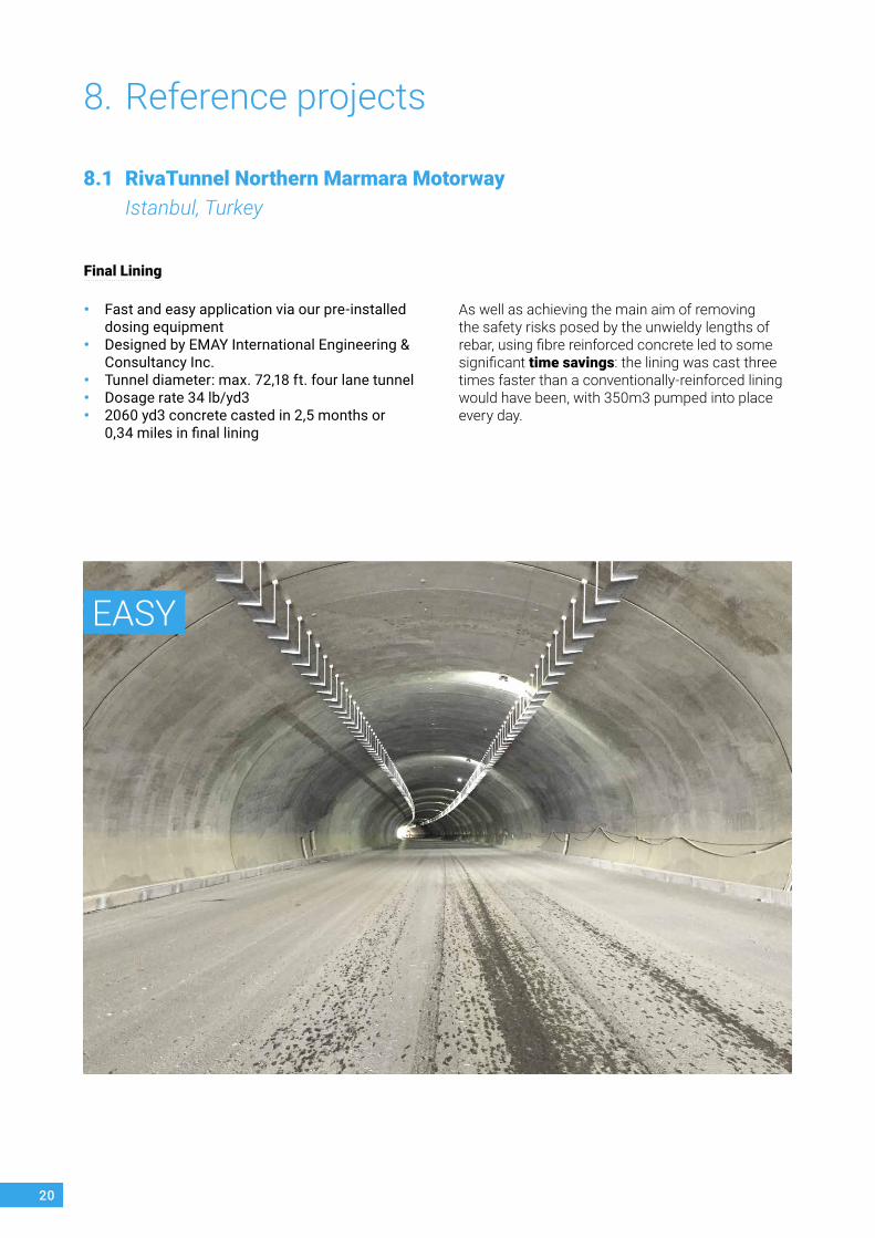
8.1 RivaTunnel Northern Marmara Motorway Istanbul, Turkey
As well as achieving the main aim of removing the safety risks posed by the unwieldy lengths of rebar, using fibre reinforced concrete led to some significant time savings: the lining was cast three times faster than a conventionally-reinforced lining would have been, with 350m3 pumped into place every day.
Final Lining
• Fast and easy application via our pre-installed dosing equipment
• Designed by EMAY International Engineering & Consultancy Inc.
• Tunnel diameter: max. 72,18 ft. four lane tunnel• Dosage rate 34 lb/yd3 • 2060 yd3 concrete casted in 2,5 months or
0,34 miles in final lining
21
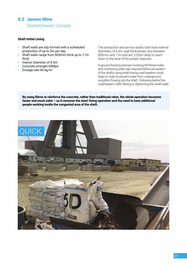
Shaft Initial Lining
• Shaft walls are slip formed with a scheduled production of up to 3m per day
• Shaft walls range from 800mm thick up to 1.1m thick
• Interior Diameter of 8.5m• Concrete strength 60Mpa• Dosage rate 40 kg/m3
The production and service shafts both have internal diameters of 6.5m, wall thicknesses vary between 800mm and 1.1m and are 1,030m deep to reach down to the level of the potash deposits.
A ground freezing exercise involving 89 freeze holes and monitoring wells was required before excavation of the shafts using shaft boring road headers could begin in order to prevent water from underground acquifers flowing into the shaft. Following behind the roadheaders, DMC Mining is slipforming the shaft walls.
8.2 Jansen Mine Saskatchewan, Canada
QUICK
By using fibres to reinforce the concrete, rather than traditional rebar, the whole operation becomes faster and much safer – as it removes the steel-fixing operation and the need to have additional people working inside the congested area of the shaft.

22
Secondary/inner lining
• About 15 000 tonnes of traditional reinforcement removed
• Designed with MC2010 by by former UnPs (now Morgan Sindall Engineering Services)
• Dosage rate 40kg/m3 (67lb/yd3)• This dosage rate provided excellent bending
hardening properties to the concrete section• $3,8 million per mile savings by using
Dramix® 5D
In addition to durability issues MVB also saved around 15,000 tonnes of steel, together with the commensurate reduction in carbon emissions. The casting process was also simplified and shortened by removing the steel fixing operation.
8.3 Lee Tunnel London, UK
COST-SAVING

23
Bibliography
• Test method for metallic fibre concrete – measuring the flexural tensile strength (limit of proportionality (LOP), residual)”. EN1461:2005, April 3rd, 2005.
• Fib Bulletins 55-56: Model Code 2010 – First complete draft. (2010)
• ISO 13 270: Steel fibres for concrete — Definitions and specifications. (First edition 2013-01-15)
• Tunnel is an art: Marc Vandewalle NV Bekaert SA 2005
• FIB Bulletin 83 precast tunnel segments in fibre reinforced concrete State-of-the-art report fib WP 1.4.1
• 5D revolution - Tunneling Journal• ISRM International Symposium 2010 and 6th Asian
Rock Mechanics Symposium - Advances in Rock
• Engineering, 23-27 October, 2010, New Delhi, India NATM – DESIGN STEPS AND CONTRACTUAL MATTERS ROBERT Brite Euram Project : sub task on durability
• Consultant’s view of durable and sustainable concrete tunnel constructions in the Middle East) Carola Edvardsen COWI WTC 2018 Dubai
• SFRC for cast-in-place (CAST IN PLACE) Permanent Linings: Thames Tideway Lee Tunnel Project in East London, UK Sotiris Psomas - Colin Eddie1 Morgan Sindall Underground Professional Services, Rugby, UK 2nd Eastern European Tunnelling Conference Athens, Greece “Tunnelling in a Challenging Environment” 28 September - 01 October 2014
531
2
Benefit from our full service
We have knowledge and extensive experience of the standards worldwide in regards to steel fibre reinforced concrete design. Using the relevant standards we can provide you with assistance in the development of your specific project’s design. This will result in a steel fibre solution tailored to your project that is sound and economical.
Dramix® steel fibres are produced in accordance with international standards such as ISO 9001 and ISO 14001.
We have a large data base of test results performed in controlled testing labs on the performance of our fibres in various concrete mixes. We have our own concrete testing lab available to support you.
Thanks to our worldwide network, we are able to offer on-site support virtually anywhere. We also offer special d osing equipment, which allows contractors to save time and work with the highest precision and quality assurance.
Our global experts bundle many years of tunnel construction experience. They closely monitor the latest developments in the field and regularly share their knowledge and opinion with the expert underground community.
4

Cop
yrig
ht ©
Inne
r lin
ing
Lee
Tunn
el
TUNNELLING APPLICATIONS:
FIBRE REINFORCEDCAST IN PLACE LINING
Because we are tunnelling
TUNNELLING APPLICATIONS:
PERMANENT SPRAY CONCRETE LINING
Because we are tunnelling
Cop
yrig
ht ©
Cro
ssra
il Lt
d
TUNNELLING APPLICATIONS:
SHOTCRETE REINFORCEMENTBecause we are tunnelling
TUNNELLING APPLICATIONS: CONCRETE SEGMENT
REINFORCEMENTBecause we are tunnelling
v1_2
020
- o
myg
od.b
e
Contact us:NV Bekaert SA Bekaertstraat 2 8550 Zwevegem - Belgium
www.bekaert.com/underground
[email protected] +32 56 76 61 10F +32 56 76 79 47
Need more in-depth technical info? Request our Tunnelling Applications Handbooks via [email protected] or download at www.bekaert.com/underground