turbine gas meter - gescompany.eu€¦ · the gas flows through an integrated flow conditioner,...
TRANSCRIPT

TURBINE GAS METER

CGT series turbine gas meters are flow meters designed to measure quantity of gases. The CGT series gas meters are applied in measurement systems where high accuracy is required:
pling, to the index unit, which is mounted on the top of the body, and shows the op-erating volume on the total-izer.
The turbine wheel, as a standard, is made of alumin-ium. This allows to provide each CGT turbine gas me-ters with HF inductive pulse sensors. There are no extra costs due to the replacement of the turbine wheel.
DESIGN AND FUNCTION
The turbine gas meter meas-ures the quantity of gas basing on the flow principle. The gas flows through an integrated flow conditioner, which distri-butes the flow proportio-nally in the annular slot and guides it to the turbine wheel. The wheel is driven by the gas flow, and the angular velocity of the rotation is proportional to the gas flow rate.
The energy consumption, perceived as pressure loss, is reduced to absolute feasible minimum due to the applica-tion of the flow conditioner, highest precision ball barings, most accurate tolerances of all measuring parts and their proper alignement.The rotary motion of the tur-bine wheel is transferred me-chanically by gear wheels, and the incorporated gas tight and hermetic magnetic cou-
1
Magnetic coupling
Index head
Meter body
Measurement cartridge
Flow conditioner
transportation of natural gas primary and secondary measurements control metering of the natural gas
and non aggressive technical gases in industry flow measurement for technical purposes
1

pressure rating: PN16 to PN110, ANSI150 to ANSI600 other rates on request
nominal diameter: DN50 up to DN400 other on request
meter bodies: cast iron or carbon steel details in table 4
flow 6 to 10 000 m3/h other on request
rangeability: up to 1:30 at atmospheric pressure higher on request
upstream pipe: minimum 2 x DN; meters meet the requirements of the OIML R32 89 Annex A
temperature range: gas temperature -20°C to +60°C ambient temperature -25°C to +70°C
allowed medias: see table 2
operating position: horizontal or vertical
2
GENERAL TECHNICAL DATA
DESIGN &
TECHNICALDATA
table 1
2
DN
1:10 1:20 1:30 1:5 1:10 1:20 1:30
Qmin(at atmospheric pres-
sure) for meters de-signed for 1.6 &2 MPa
HF3÷HF6HF1, HF2LF
QmaxG Qmin(at atmospheric pressure)
for meters designed for 5, 6.4, 10, & 11 MPa
LF values andapproximate HF
values
m3/h m3/h m3/h m3/h m3/h m3/h m3/h m3/h pulse/m3pulse/m3pulse/m3--
50
80
100
150
200
250
300
400
40
65
100
160
250
160
250
400
400
650
1000
650
1000
1600
1000
1600
2500
1600
2500
4000
2500
4000
6500
65
100
160
250
400
250
400
650
650
1000
1600
1000
1600
2500
1600
2500
4000
2500
4000
6500
4000
6500
10000
6
10
16
25
40
-
-
-
-
-
-
-
-
-
-
-
-
-
-
-
-
-
-
-
5
8
13
20
13
20
32
32
50
80
50
80
130
80
130
200
130
200
320
200
320
500
-
-
-
-
-
-
13
20
20
32
50
32
50
80
50
80
130
80
130
200
130
200
320
13
20
32
50
80
50
80
130
130
200
320
-
-
-
-
-
-
-
-
-
-
-
-
6
10
16
25
40
25
40
65
65
100
160
100
160
250
160
250
400
250
400
650
400
650
1000
-
-
8
13
20
13
20
32
32
50
80
50
80
130
80
130
200
130
200
320
200
320
500
-
-
-
-
-
-
-
20
20
32
50
32
50
80
50
80
130
80
130
200
130
200
320
2610
2610
1081
844
470
1383
632
401
302
227
129
114
116
67
58
58
34
32
32
19
7
7
7
94829
94829
42563
30652
17059
29309
16782
9719
7331
6873
3910
3113
3167
2025
2111
2111
1223
1181
1181
680
242
242
285
10
1
1
1
0,1
1
0,1
0,1
0,1
0,1

3
fig.2: Measurement error typical curve at low pressure (average 1 bar a) green curve
at high pressure (over 5 bar a) blue curve
Gas
Argon
Butane
Carbon dioxide
Carbon monoxide
Ethane
Ethylene
Helium
Methane
Natural gas
Nitrogen
Propane
Acetylene
Hydrogen
Air
Ar
C4H10
CO2
CO
C2H6
C2H4
He
CH4
-
N2
C3H8
C2H2
H2
-
Chemical symbol
(formula)
1,66
2,53
1,84
1,16
1,27
1,17
0,17
0,67
~0,75
1,16
1,87
1,09
0,084
1,20
Density ρ[kg/m3]
1,38
2,10
1,53
0,97
1,06
0,98
0,14
0,55
~0,63
0,97
1,56
0,91
0,07
1,00
Density related to air
standard IIB
standard IIB
standard IIB
standard IIB
standard IIB
standard IIB
standard IIB
standard IIB
standard IIB
standard IIB
standard IIB
special IIC
special IIC
standard IIB
Gas meterexecution
measurement accuracy: EU requirements and better guaranteed at least: 0.2 Qmax – Qmax < ± 1% Qmin – 0.2 Qmax < ± 2%
MEASUREMENT OUTPUTS
PULSE SENSORS
Error%
+2
+1
0
-1
-2
Q min,ρQ min Q t Q max Q
table 2: Physical properties of most popular gases that may be measured with the CGT turbine gas meters - density at 101,325 kPa and at 20˚C
The mechanical index unit indicates the actual volume of the measured gas at operat-ing temperature and operating pressure. It can be rotated axially by 350° in order to facilitate the readings and enable easier connection of pulse sensor plugs.The index unit is provided with one low frequency LFK reed contact pulse transmitter, as a standard. On request the index may be equipped with:- LFI inductive pulse sensors (NAMUR)- HF inductive pulse sensors (NAMUR)
PRESSURE AND TEMPERATURE OUTPUTS
The operating pressure (reference pressure) can be taken from the pressure taps, marked pr, located on both sides of the meter body.The meters can be optionally equipped with two temperature taps for the measure-ment of the gas temperature.
3

4
MEASUREMENT OUTPUTS
fig. 2. Location of measurement outputs (top view)
The CGT turbine gas meters may be provided with up to 10 pulse sensors for DN100 – DN300 and up to 8 pulse sensors for DN50 – DN80
LFK – low frequency reed contact pulse sensor LFK1, LFK2LFI – low frequency inductive pulse sensor LFI1, LFI2HF – inductive pulse sensor in the index unit HF1, HF2HF – inductive pulse sensor over the turbine wheel HF3, HF4HF – inductive pulse sensor over the reference wheel HF5, HF6AFK – anti-fraud reed contact AFK
The sockets in the index match the TUCHEL plug no C091 31H006 100 2fig. 3 Pulse sensor PIN numbering in sockets 1 and 2 installed in the index
The sockets of optional HF3, HF4, HF5, HF6 pulse sensors match the TUCHEL plug no C091 31D004 100 2. For connections, please use PIN 3 and PIN 4.table 4: Permissible supply parameters of intrinsically safe circuits for HF3, HF4, HF5, and HF6.
HF (index)
Ui = 20 V DC
I i = 60 mA
Pi = 80 mW
Li = 150 μH
Ci = 150 nF
LFI
Ui = 20 V DC
I i = 60 mA
Pi = 130 mW
Li ≈ 350 μH
Ci = 250 nF
LFK
Ui = 15,5 V DC
I i = 52 mA
Pi = 169 mW
Li ≈ 0
Ci ≈ 0
table 3: Permissible supply parameters of intrinsically safe circuits.
-
+
-
+
-
+
-
+
-
+
-
+
S1
4
2
5
3
6
1
4
2
5
3
6
Socket 1
Socket 2
LFK 1 LFK 2 AFK LFI 1 LFI 2 HF 1 HF 2polarityPIN
S
O
P
O
O
P
O
P
O
O
P
O
O
O
P
O
O
O
P
O
O
O
P
O
P
P
O
P
O
O
O
P
O
O
P
S - standard connection P - preferred connection O – alternative connection
CHFI-02
Bi3-EG12-RY1
Bi1-EG05-Y1
NJ08-5GM-N-Y07451
15,5
20
20
16
52
60
60
25
169
200
80
64
40
150
150
50
28
150
150
20
HF3 HF4 HF5 HF6 Ui [ V ] I i [mA] Pi [mW ] Li [μH] Ci [nF]

5
Overall dimensions and weights of CGT turbine gas meters are shown in Table 4
table 4
fig.5 Dimensions of the CGT turbine gas meter
DIMENSIONS AND WEIGHTS
DN
mm mm mm mm mm mm kg
L A B C E;F weight
Size E is valid for: PN16, PN20, PN50, ANSI150, ANSI300Size F is valid for: PN63/64, PN100, ANSI600
50
80
100
150
4
Flange body
PN16PN20/ANSI150
PN16PN20/ANSI150PN50/ANSI300
PN63/64PN100
PN110/ANSI600PN16
PN20/ANSI150PN16
PN20/ANSI150PN50/ANSI300
PN63/64PN100
PN110/ANSI600PN16
PN20/ANSI150PN16
PN20/ANSI150PN50/ANSI300
PN63/64PN100
PN110/ANSI600PN16
PN20/ANSI150PN16
PN20/ANSI150PN50/ANSI300
PN63/64PN100
PN110/ANSI600
150
240
300
450
198
201
215
242
42
60
80
101
125
155
58
95
124
180
150
216
146
212
157
223
185
251
98
1211121517131918242427283230242532344239465247466464808696
105
DN
mm mm mm mm mm mm kg
L A B C E;F weight
200
250
300
400
Flange body
PN16PN20/ANSI150
PN16PN20/ANSI150PN50/ANSI300
PN63/64PN100
PN110/ANSI600PN16
PN20/ANSI150PN50/ANSI300
PN63/64PN100
PN110/ANSI600PN16
PN20/ANSI150PN50/ANSI300
PN63/64PN100
PN110/ANSI600PN16
PN20/ANSI150PN50/ANSI300
PN63/64PN100
PN110/ANSI600
600
750
900
1200
202
268
232
298
258
324
387
70717071
100115130140130130175190230250190200260270330340350390480490610580
cast
ir
on
stee
lca
st
iro
nst
eel
cast
ir
on
cast
ir
on
stee
lst
eel
cast
ir
on
stee
l
cast
ir
on
stee
lst
eel
stee
lst
eel
265
293
318
354
212
270
300
500
240
330
350
400
6
DIMENSIONS &PERFORMANCE
PRESSURE LOSS5
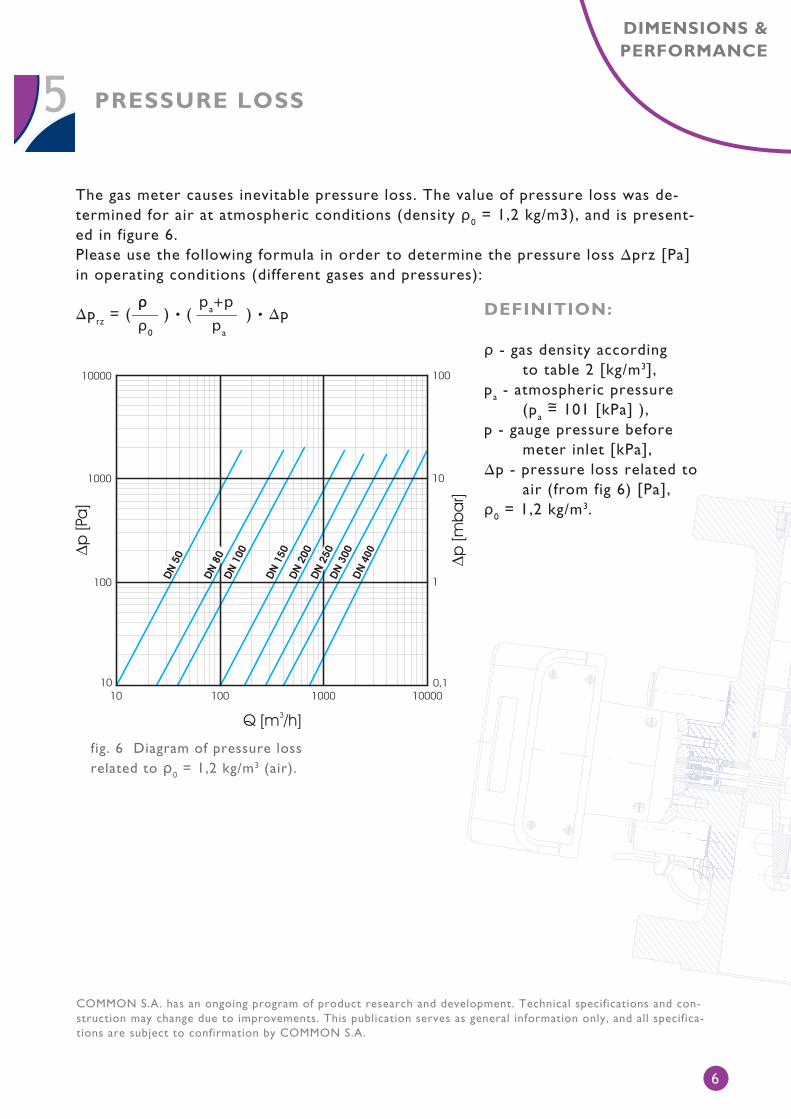
The gas meter causes inevitable pressure loss. The value of pressure loss was de-termined for air at atmospheric conditions (density ρ0 = 1,2 kg/m3), and is present-ed in figure 6.Please use the following formula in order to determine the pressure loss ∆prz [Pa] in operating conditions (different gases and pressures):
DEFINITION:
ρ - gas density according to table 2 [kg/m3],pa - atmospheric pressure (pa = 101 [kPa] ),p - gauge pressure before meter inlet [kPa],∆p - pressure loss related to air (from fig 6) [Pa],ρ0 = 1,2 kg/m3.
∆p rz = ( ) • ( ) • ∆p ρρρ0
pa+ppa
fig. 6 Diagram of pressure loss related to ρ0 = 1,2 kg/m3 (air).
~
COMMON S.A. has an ongoing program of product research and development. Technical specifications and con-struction may change due to improvements. This publication serves as general information only, and all specifica-tions are subject to confirmation by COMMON S.A.