turbo cell control electronics - artistic pool and spaartisticpoolandspa.com/pdfs/prologic 4.40...
TRANSCRIPT

Turbo Cell
&
Control
Electronics
Pro Logic Version Rev. 4.45
Diagnostics
Manual
Copyright 2014 Hayward Industries Inc.

Table of Contents
Important safety instructions Pg. 1 Adjusting Chlorinator Output Pg. 17
Pro Logic Board Layout Diagram Pg. 2 Configuring Cell Type Pg. 18
‘No Cell Power 1’ & ‘No Cell Power 2’ Pg. 3 ‘High Salt/Amps’ error message Pg. 19
‘No Cell Power’ & ‘Low Volts’ error message
diagnostics Pg. 4-8 Cell cleaning instructions Pg. 20-22
‘Cell Power Error’ message diagnostics Pg. 9 ‘Comm Error 1’ and ‘Comm Error 2’ Pg. 23-24
‘Chlorinator Off-Test Salt Level’ error message Pg. 10 Diagnostic flow charts Pg. 25-29
Blank or no display Pg. 11-13 Additional ‘Check System’ errors Pg. 30-32
‘Low Temperature’ & ‘High Temperature’ error
messages Pg. 14 Temperature vs. resistance chart Pg. 33
‘Low Salt’ & ‘Very Low Salt’ error messages Pg. 15 Software revisions/compatibility chart Pg. 34-39
Resetting the salt reading Pg. 16 Chlorinator output notes Pg. 40
! Warning
High Voltage Electrocution Hazard
Hazardous voltage can shock, burn, cause serious injury
and or death. To reduce the risk of electrocution and or
electric shock hazards:
• Only qualified technicians should remove the panel
• Replace damaged wiring immediately
• Insure panel is properly grounded and bonded
Page 1
Pro Logic Version 4.40 Diagnostics
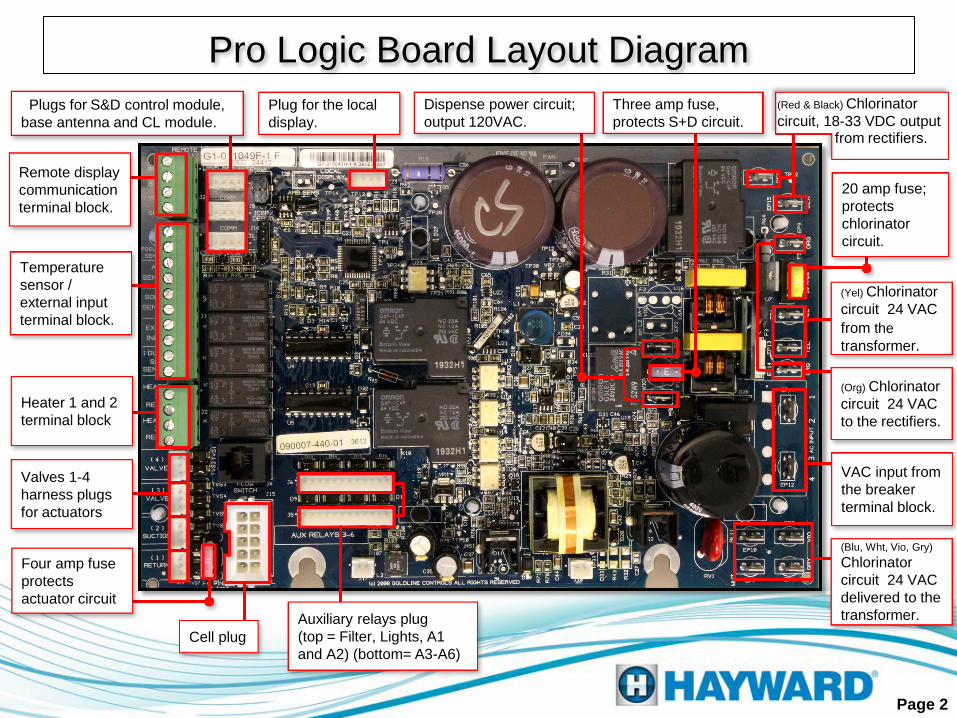
Pro Logic Board Layout Diagram
Cell plug
Dispense power circuit;
output 120VAC. Plugs for S&D control module,
base antenna and CL module.
Plug for the local
display.
Auxiliary relays plug
(top = Filter, Lights, A1
and A2) (bottom= A3-A6)
Four amp fuse
protects
actuator circuit
Valves 1-4
harness plugs
for actuators
Heater 1 and 2
terminal block
Temperature
sensor /
external input
terminal block.
Remote display
communication
terminal block.
Three amp fuse,
protects S+D circuit.
(Yel) Chlorinator
circuit 24 VAC
from the
transformer.
VAC input from
the breaker
terminal block.
(Red & Black) Chlorinator
circuit, 18-33 VDC output
from rectifiers.
20 amp fuse;
protects
chlorinator
circuit.
(Org) Chlorinator
circuit 24 VAC
to the rectifiers.
(Blu, Wht, Vio, Gry)
Chlorinator
circuit 24 VAC
delivered to the
transformer.
Page 2
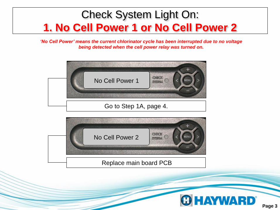
‘No Cell Power’ means the current chlorinator cycle has been interrupted due to no voltage
being detected when the cell power relay was turned on.
Page 3
Check System Light On:
1. No Cell Power 1 or No Cell Power 2
No Cell Power 1
No Cell Power 2
Go to Step 1A, page 4.
Replace main board PCB
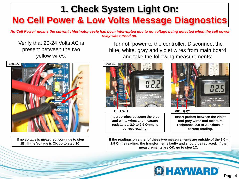
Verify that 20-24 Volts AC is
present between the two
yellow wires.
If no voltage is measured, continue to step
1B. If the Voltage is OK go to step 1C.
‘No Cell Power’ means the current chlorinator cycle has been interrupted due to no voltage being detected when the cell power
relay was turned on.
Page 4
Turn off power to the controller. Disconnect the
blue, white, gray and violet wires from main board
and take the following measurements:
Insert probes between the blue
and white wires and measure
resistance. 2.0 to 2.9 Ohms is
correct reading.
Insert probes between the violet
and grey wires and measure
resistance. 2.0 to 2.9 Ohms is
correct reading.
BLU WHT VIO GRY
If the readings on either of these two measurements are outside of the 2.0 –
2.9 Ohms reading, the transformer is faulty and should be replaced. If the
measurements are OK, go to step 1C.
1. Check System Light On:
No Cell Power & Low Volts Message Diagnostics
Step 1B Step 1A

Verify the chlorinator is not in an ‘off’ cycle.
If it is, reverse polarity and proceed, with
the filter pump on.
Page 5
All zeros, except temperature means the chlorinator is off.
Press the plus (+) or minus (–) key.
The chlorinator will conduct a 15 second count down prior
to starting. Go to Step 1D.
Verify that 20-24 Volts AC is present
between the two orange wire
connections. Step 1D
If the voltage is low or not present go to step 1E. If the
voltage is OK, go to step 1F.
1. Check System Light On
No Cell Power & Low Volts Message Diagnostics
Press the ‘MENU’ key until ‘Diagnostic Menu’ is displayed.
Then press right arrow key.
Step 1C
Step 1F
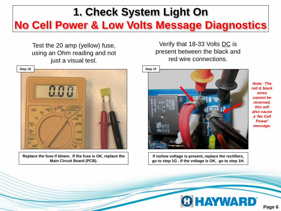
Verify that 18-33 Volts DC is
present between the black and
red wire connections.
If no/low voltage is present, replace the rectifiers,
go to step 1G . If the voltage is OK, go to step 1H.
Note: The
red & black
wires
cannot be
reversed,
this will
also cause
a ‘No Cell
Power’
message.
Page 6
Test the 20 amp (yellow) fuse,
using an Ohm reading and not
just a visual test.
Replace the fuse if blown. If the fuse is OK, replace the
Main Circuit Board (PCB).
1. Check System Light On
No Cell Power & Low Volts Message Diagnostics
Step 1E

The rectifiers are both located
beneath the transformer. It is
important, when replacing the
rectifiers to connect the wires in
accordance with the instructions.
Page 7
1. Check System Light On
No Cell Power & Low Volts Message Diagnostics
Step 1G BLK
RED
ORG BLK
RED ORG
Note: The bottom right corner of each rectifier should be cutoff. If
this is not correct, loosen them and rotate each block until they
appear like the diagram below.
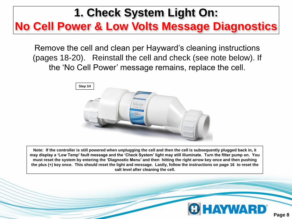
Remove the cell and clean per Hayward’s cleaning instructions
(pages 18-20). Reinstall the cell and check (see note below). If
the ‘No Cell Power’ message remains, replace the cell.
Note: If the controller is still powered when unplugging the cell and then the cell is subsequently plugged back in, it
may display a ‘Low Temp’ fault message and the ‘Check System’ light may still illuminate. Turn the filter pump on. You
must reset the system by entering the ‘Diagnostic Menu’ and then hitting the right arrow key once and then pushing
the plus (+) key once. This should reset the light and message. Lastly, follow the instructions on page 16 to reset the
salt level after cleaning the cell.
Page 8
1. Check System Light On:
No Cell Power & Low Volts Message Diagnostics
Step 1H
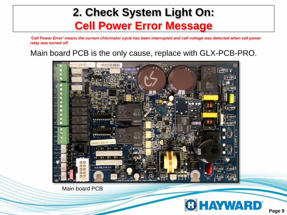
Main board PCB
Main board PCB is the only cause, replace with GLX-PCB-PRO.
‘Cell Power Error’ means the current chlorinator cycle has been interrupted and cell voltage was detected when cell power
relay was turned off.
Page 9
2. Check System Light On:
Cell Power Error Message

Verify the system is configured for correct model cell. (Page 18).
If the incorrect cell is chosen, the system will inaccurately interpret the
salt level in the pool and the system may turn the chlorinator off.
Maximum Current (Amps) before shutdown
Page 10
3. Chlorinator Off:
Test Salt Level Message
T-CELL-3 5.50 T-CELL-9 10.00
T-CELL-5 6.75 T-CELL-15 10.00
4. Local Display:
Blank/No Lights
Page 11
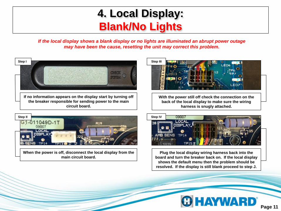
If the local display shows a blank display or no lights are illuminated an abrupt power outage
may have been the cause, resetting the unit may correct this problem.
If no information appears on the display start by turning off
the breaker responsible for sending power to the main
circuit board.
When the power is off, disconnect the local display from the
main circuit board. Plug the local display wiring harness back into the
board and turn the breaker back on. If the local display
shows the default menu then the problem should be
resolved. If the display is still blank proceed to step J.
Step I
Step II
Step III
With the power still off check the connection on the
back of the local display to make sure the wiring
harness is snugly attached.
Step IV

Unplug the bus strip for ‘Remote Display’
as well as the wireless antennae (base
station) if applicable. Shut the system
down and power back up. If the display
returns, plug each connector back in,
one at a time, to determine which is
affecting the display. Repair or replace
any device(s) or wiring that affects the
display. If this does not correct the
issue, go to Step 4D.
Page 12
Remove the black and white wires
(from the incoming power). Verify that
115-120 Volts AC is present across
these leads.
If no/low voltage is measured, check
connections at the terminal block. Confirm
breaker, within the system’s sub-panel and
main power source, are both turned on. If no
voltage is still present, go to Step 4B. If
proper voltage is present, go to Step 4C.
4. Local Display:
Blank/No Lights
Step 4A
Measure 110-120 Volts
AC at the terminal
block coming from the
breaker. If under 110-
120 Volts AC then
check the breaker. If
the breaker is faulty
replace and go back to
step 4C.
Step 4B
Step 4C
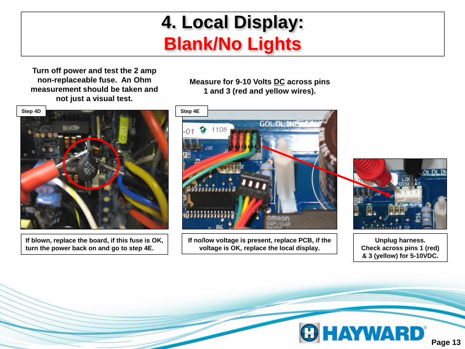
Measure for 9-10 Volts DC across pins
1 and 3 (red and yellow wires).
Step 4E
If no/low voltage is present, replace PCB, if the
voltage is OK, replace the local display.
Unplug harness.
Check across pins 1 (red)
& 3 (yellow) for 5-10VDC.
Page 13
Turn off power and test the 2 amp
non-replaceable fuse. An Ohm
measurement should be taken and
not just a visual test.
If blown, replace the board, if this fuse is OK,
turn the power back on and go to step 4E.
Step 4D
4. Local Display:
Blank/No Lights

1. Check the water temperature. If the temperature is below 50°F the system will shut the cell down
under normal circumstances.
2. If the controller is still powered, when unplugging the cell and then the cell is subsequently plugged
back in, it may display a ‘Low Temp’ fault message and the ‘Check System’ light may still illuminate.
Turn the filter pump on. You must reset the system by entering the ‘Diagnostic Menu’ and then hitting
the right arrow key once and then pushing the plus key once. This should reset the light and message.
3. Replace the cell.
High Temperature Error Message
1. Check the water temperature. Temperature above 140°F the system will shut the cell down under
normal circumstances.
2. Replace the cell.
‘Chlorinator Off Low Temperature’ means the current chlorinator cycle has been interrupted
due to a cell temperature reading of less than 50°F.
‘Chlorinator Off High Temperature’ means the current chlorinator cycle has been interrupted
due to a cell temperature reading of more than 140°F.
Page 14
Check System Light On:
Low Temperature Error Message

Low Salt Error Message A low salt error means the average salt level is less than or equal to 2600 PPM. Cell is still operating.
1. Test the salt level in the pool using a suitable tester. Be sure the tester has been calibrated and is
clean. Add salt as needed to bring up to the 3200 PPM level.
2. Remove and clean cell per the Hayward’s cleaning instructions. Be sure to ‘reset’ the average salt
by following the instructions on page 16. Replace cell if message is still displayed after cleaning.
Very Low Salt Error Message
1. Test the salt level in the pool using a suitable independent tester. Be sure the tester has been
calibrated and is clean. Add salt as needed to bring up to the 3200 PPM level.
2. Check to make sure system is configured for correct model cell (page 18).
3. Remove and clean cell per the Hayward cleaning instructions. Be sure to ‘reset’ the average salt
by following the instructions on page 16. Replace cell if message is still displayed after cleaning.
A very low salt error means the average salt level is less than or equal to 2300 PPM. Cell has shut down.
Page 15
Check System Light On:

The salt reading displayed in the ‘Default – Menu’ is actually an average salt reading. This average is calculated by using previous instant
salt readings over a period of time. When diagnosing and repairing faults relating to high or low salt readings, it will be necessary to ‘reset’
the average salt by replacing it with the instant value in order to prevent the same fault from appearing at startup. Resetting will flush out any
previously stored values and start averaging using the instant salt reading as the first value. For example, imagine if the system faulted on a
very low salt reading and the fault was because the cell was dirty. The cell is then cleaned and reinstalled. The average salt reading that
prompted the fault is still in the memory. When the clean cell is installed, it will once again consider this low average and fault again, it may
take 48 hours before the average rises to the correct levels with the clean cell. By resetting to the instant level, we avoid this problem.
To display the ‘Diagnostic Menu’, press the ‘MENU’ key
until ‘Diagnostic Menu’ appears. Then press right arrow
key one time.
If all zeros or if ‘Chlorinator Off Percentage Met’ appears,
it is in an off cycle. Press plus (+) or minus (–) key. The
system will keep the chlorinator off due to a short start
delay. If, after the short start delay, the display does not
show zeros again refer to step 3.
Press the plus (+) key to save the instant salt reading and
this will start the average process over again. Press the
left arrow key to return to the data display and you will see
an updated salt level in PPM on the display.
The above is an example of the updated salt reading in
PPM. If this instant salt reading varies from the average
press the right arrow key one time.
Page 16
Filter pump on
Resetting (Average) Salt Reading
Step I
Step II
Step III
Step IV
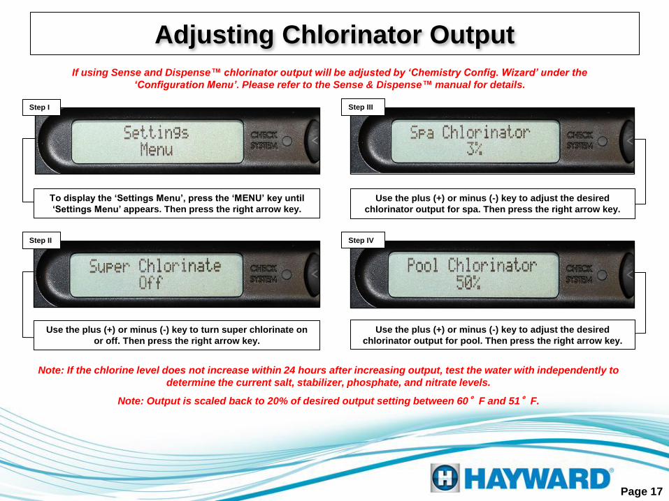
To display the ‘Settings Menu’, press the ‘MENU’ key until
‘Settings Menu’ appears. Then press the right arrow key.
Use the plus (+) or minus (-) key to turn super chlorinate on
or off. Then press the right arrow key.
Use the plus (+) or minus (-) key to adjust the desired
chlorinator output for spa. Then press the right arrow key.
Use the plus (+) or minus (-) key to adjust the desired
chlorinator output for pool. Then press the right arrow key.
If using Sense and Dispense™ chlorinator output will be adjusted by ‘Chemistry Config. Wizard’ under the
‘Configuration Menu’. Please refer to the Sense & Dispense™ manual for details.
Note: If the chlorine level does not increase within 24 hours after increasing output, test the water with independently to
determine the current salt, stabilizer, phosphate, and nitrate levels.
Note: Output is scaled back to 20% of desired output setting between 60°F and 51°F.
Page 17
Adjusting Chlorinator Output
Step I
Step II
Step III
Step IV

Page 18
It is important to verify which cell type is being used and to make sure
the system is configured for the correct model cell.
Configuring Cell Type
Step I
Step II
Step III
Step IV
Press the ‘MENU’ key until the ‘Configuration Menu-
Locked’ appears on the screen. To unlock the
‘Configuration Menu’ press and hold the left and right
arrow keys for five to ten seconds.
Once the ‘Configuration Menu’ is unlocked press the right
arrow key once. ‘Chlor. Config. + to view/change’ should
appear on the display. Press the plus (+) key to enter.
The ‘Cell Type’ display will indicate the model of cell the
system is expecting. If this screen is not configured for
the correct cell type press the plus (+) or minus (-) key
until the appropriate cell is expressed.
The display should show ‘Chlorinator Enabled’ if not,
press the plus key to ‘Enable’ it. Then scroll to the right
two times.
Note: If the ‘Cell Type’ option does not appear in the ‘Chlor. Config.’ menu, then review the system’s model number
to identify the type of cell that should be used with the system. Some earlier board revisions could not be
configured for different cell types.
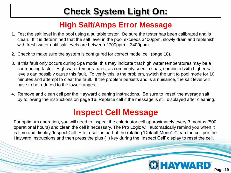
1. Test the salt level in the pool using a suitable tester. Be sure the tester has been calibrated and is
clean. If it is determined that the salt level in the pool exceeds 3400ppm, slowly drain and replenish
with fresh water until salt levels are between 2700ppm – 3400ppm.
2. Check to make sure the system is configured for correct model cell (page 18).
3. If this fault only occurs during Spa mode, this may indicate that high water temperatures may be a
contributing factor. High water temperatures, as commonly seen in spas, combined with higher salt
levels can possibly cause this fault. To verify this is the problem, switch the unit to pool mode for 10
minutes and attempt to clear the fault. If the problem persists and is a nuisance, the salt level will
have to be reduced to the lower ranges.
4. Remove and clean cell per the Hayward cleaning instructions. Be sure to ‘reset’ the average salt
by following the instructions on page 16. Replace cell if the message is still displayed after cleaning.
Inspect Cell Message For optimum operation, you will need to inspect the chlorinator cell approximately every 3 months (500
operational hours) and clean the cell if necessary. The Pro Logic will automatically remind you when it
is time and display ‘Inspect Cell, + to reset’ as part of the rotating ‘Default Menu’. Clean the cell per the
Hayward instructions and then press the plus (+) key during the ‘Inspect Cell’ display to reset the cell.
Page 19
High Salt/Amps Error Message
Check System Light On:

Cell cleaning frequency is dependent on several factors; pH and calcium levels in the water are the two that have the
greatest effect on how often the cell requires cleaning. Maintaining pH at the levels recommended in the operating
instructions (7.2 - 7.8) should result in the cell being cleaned 3-4 times a year in areas with hard water. Cells may be cleaned
less frequently in soft water areas.
After removing the Turbo Cell from the plumbing of your pool; inspect the cell for white deposits between the plates inside of
the cell. Please remember that even if you cannot see visible deposits in the chamber, it still may require cleaning. If no
deposits are found (picture to the left), the cell may have to be held towards ample amounts of light and angled in different
directions to reveal smaller white deposits deeper within the nest of the cell.
Hold to light to
look for small deposits Cell is dirty.
Note the deposits.
ALWAYS ADD ACID TO WATER, NEVER WATER TO ACID. ALWAYS WEAR PROPER
EYE PROTECTION AND PROTECTIVE GLOVES. USE IN A WELL VENTILATED AREA.
MURIATIC AND OTHER ACIDS CAN CAUSE SEVERE INJURY, BURNS AND
RESPIRATORY PROBLEMS IF NOT HANDLED PROPERLY. REFER TO THE
MANUFACTURER’S DIRECTIONS FOR SAFE HANDLING.
!
Page 20
CAUTION
!
Cell Cleaning Instructions:

Mix 1 part acid to 4 parts water. Stand the cell vertically in the solution.
The level of the solution should be slightly over the product label. Let the
cell stand in the solution for 15 minutes (Fig. 6A to the right), then flip the
cell over and let stand on the other end (Fig. 6B to the right) for an
additional 15 minutes. Although the cord can be submerged, be sure that
the connector does not come in contact with the solution.
Inspect the cell after both sides have soaked. If there are no deposits after
soaking, rinse with water and reinstall. If there are still deposits after
soaking, repeat the soaking procedure until clean. The water/muriatic acid
mixture can be stored for later use or it can be disposed. Follow chemical
manufacturer’s recommendations when storing or disposing the water/acid
solution.
After you inspect the cell (and clean, if necessary) press the plus (+) key
during the ‘Inspect Cell’ display to reset the light.
Cleaning instructions using a container.
Page 21
6A 6B
Cell Cleaning Instructions:

Follow the same safety and mixing instructions as described when using a container (pages 20 and 21). Mix enough solution to
fill the inside of the cell ( Approximately 1.5 qts).
Fasten the cell to the T-Cell Cleaning Stand with the cord side down (Fig. 6C below). Before filling cell with muriatic acid solution,
put a container underneath to avoid any spills damaging the surrounding area. Fill the cell to the top with the solution (mix 1 part
acid to 4 parts water) and let soak for 15 minutes (Fig. 6D below). Empty the cell and inspect. If the cell is clean, rinse with water
and reinstall. If there are still deposits after soaking, repeat the soaking procedure until clean. The water/muriatic acid mixture
can be stored for later use or it can be disposed of. Follow the chemical manufacturer’s recommendations when storing or
disposing the water/acid solution.
After you inspect the cell (and clean, if necessary) press the plus (+) key during the ‘Inspect Cell’ display to reset the light. If the
cell was cleaned because a fault was indicated, such as ‘low salt’, or ‘very low salt’, be sure to reset the average salt reading by
following the instructions on page 16.
Page 22
Using the Hayward T-Cell Cleaning Stand
Cell Cleaning Instructions:
6C 6D

Page 23
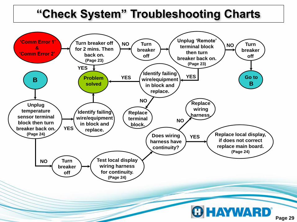
5. Comm Error 1 and Comm Error 2
Turn the system’s main power breaker
off, leave off for 2 minutes, then turn
back on and check the display.
Step 5A
If the communication error is gone then the problem should
be resolved. If the problem still exists turn the breaker off
again and proceed to step 5B.
Unplug the terminal block labeled
‘Remote’ then turn the breaker back
on (with the block still removed).
If the problem disappears when the block is removed
the remote wiring is faulty, the block is bad, the
remote is failing or the remote is not in the same
family as the local display. If problem still persists
turn the breaker off again and proceed to step 5C.
Step 5B
‘Comm Error 1’ is usually a false error caused by an abrupt power outage.
‘Comm Error 2’ is usually a misplaced wire in the sensor terminal block, a failing wired
remote, a failing local display or a failing main circuit board.

Page 24
Unplug green terminal block that contains
all the sensors then turn the breaker back
on (with the block still removed).
5. Comm Error 1 and Comm Error 2
If the communication error disappears
then check everything wired into the
sensor terminal block. If the problem
still exists proceed to step 5D.
Step 5C
Check the local display wiring
harness for continuity.
If the wiring harness does not show continuity through
any of the four terminals, replace the wiring harness. If it
is good then replace local display. If replacing the display
does not correct problem then replace the main board.
Step 5D

No Cell Power
& Low Volts
20-24 VAC
between yellow
wires on PCB
MAIN
NO
YES
(Page 4)
20-24 VAC
between orange
wires
NO
YES
(Page 5)
Ohm out
transformer leads,
blue & white: 2.0-2.9
gray & violet: 2.0-2.9
NO
YES
(Page 4)
Check
20 amp fuse for
continuity
NO
YES
(Page 5)
Chlorinator
in “OFF” cycle
(Page 5)
Go to
A
A
Replace
transformer
(Page 4)
Reset
chlorinator
(Page 6)
NO Replace
fuse
YES
18-33 VDC
between black
& red wires
(Page 6)
YES
NO
Replace
rectifiers (Page 7)
Remove cell &
clean per cleaning
instructions
NO
Replace
cell Replace
PCB
Page 25
(Page 8)
NO
“Check System” Troubleshooting Charts
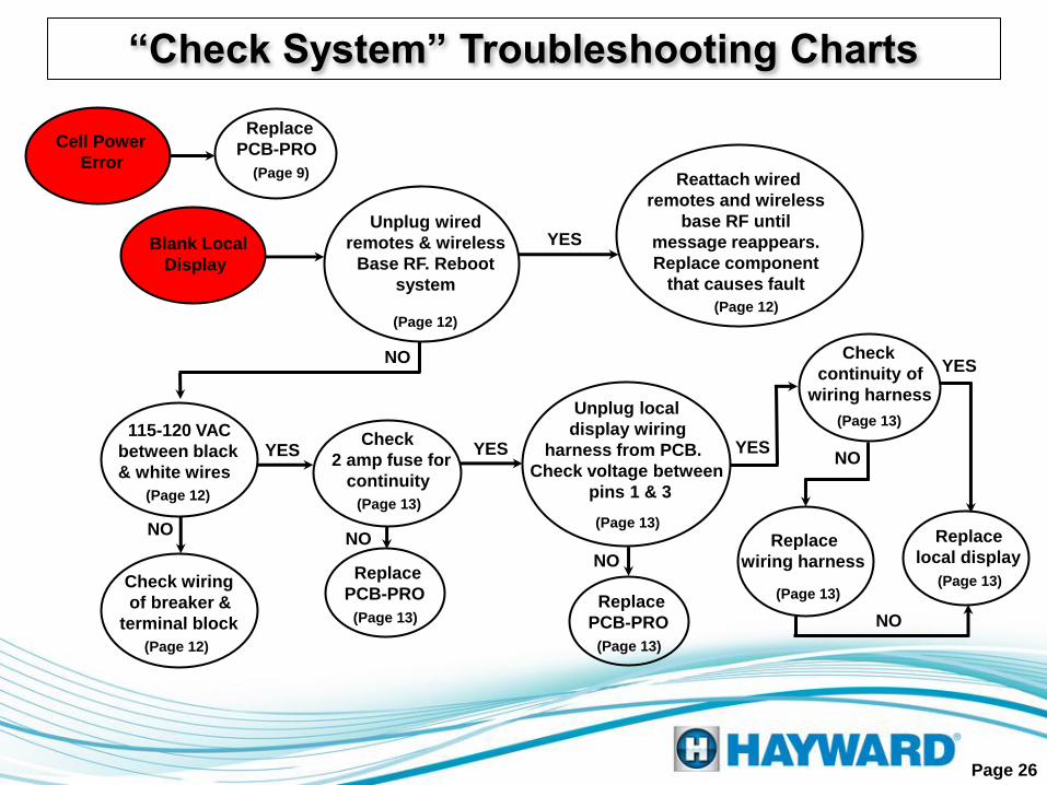
Cell Power
Error (Page 9)
Replace
PCB-PRO
Blank Local
Display
(Page 12)
Unplug wired
remotes & wireless
Base RF. Reboot
system
NO
YES
Check
2 amp fuse for
continuity
(Page 12)
Reattach wired
remotes and wireless
base RF until
message reappears.
Replace component
that causes fault
YES YES
(Page 13)
Unplug local
display wiring
harness from PCB.
Check voltage between
pins 1 & 3
YES
NO
(Page 13)
Replace
PCB-PRO
Check
continuity of
wiring harness
YES
NO
(Page 13)
Replace
local display
(Page 13)
Replace
wiring harness
115-120 VAC
between black
& white wires
(Page 12)
NO
Check wiring
of breaker &
terminal block
(Page 12)
(Page 13)
NO
Page 26
(Page 13)
(Page 13)
Replace
PCB-PRO
NO
“Check System” Troubleshooting Charts

(Page 14)
Water temp.
below 50o F
YES
Low Salt Error
(2400-2600ppm)
NO
Normal
operation (Page 14)
Reset
system (Page 14)
NO Replace
cell
(Page 14)
Water temp.
above 140o F
YES
NO
Replace
cell
High
Temperature
Error
Normal
operation (Page 14)
(Page 15)
Salt level is
2700-3400ppm YES
NO
Raise salt
level to
3200ppm
Clean
cell
Replace
cell
Reset average
salt level
(Page 15)
NO
Page 27
Configured for
correct cell? (Page 18)
YES
Very Low Salt
Error
(<2400ppm)
NO
Low
Temperature
Error
NO Configure to
correct cell. (Page 18)
Reset average
salt level
(Page 16)
NO
“Check System” Troubleshooting Charts

High Salt/Amps
Error
(>8.0 amps) (Page 19)
Salt level is
2700-3400ppm
YES
NO
Lower salt
level to
3200ppm
Clean
cell
Replace
cell
Reset average
salt level (Page 16)
NO
YES
Problem only occurs
when switching from
pool to spa mode.
(Page 18)
NO
YES
(Page 19)
Reduce salt
level
Inspect Cell
(Default Menu)
Remove cell
from plumbing
and inspect cell
cleanliness
Cell is
clean
YES
NO
Clean
cell
YES
Reset 500
operational hour
countdown timer
(Page 19)
Page 28
Configured for
correct cell? (Page 18)
Configure for
correct cell (Page 18)
NO
YES
YES
“Check System” Troubleshooting Charts
NO
‘Comm Error 1’
&
‘Comm Error 2’
NO
YES
Test local display
wiring harness
for continuity. (Page 24)
NO
Page 29
Turn breaker off
for 2 mins. Then
back on. (Page 23)
YES
YES
“Check System” Troubleshooting Charts
Problem
solved
Turn
breaker
off
Unplug ‘Remote’
terminal block
then turn
breaker back on. (Page 23)
NO Turn
breaker
off
Unplug
temperature
sensor terminal
block then turn
breaker back on. (Page 24)
Go to
B B
Turn
breaker
off
Identify failing
wire/equipment
in block and
replace.
YES
NO
Identify failing
wire/equipment
in block and
replace.
Replace
terminal
block.
Replace
wiring
harness.
Does wiring
harness have
continuity?
NO
YES Replace local display,
if does not correct
replace main board. (Page 24)

Below is a list of additional “Check System” error codes which relate to
the Pro Logic’s operation with Hayward’s TriStar Energy Solution™
Variable Speed Pump & Control. All errors may be prefaced with Pool
Filter (or Spa Filter (Dual Equipment) or Lights or Aux 1…14):
Please refer to the pump service manual for detailed troubleshooting.
Page 30
Note: If Variable Speed Pump is not being used, change Filter Pump type in the ‘Configuration Menu’ to
remove these error codes
Additional “Check System” Errors
• VSP Comm Error
• VSP Drive Comm Error
• VSP Err: xx
• Mains voltage low
• Mains voltage high
• Rmt Stop is pressed
• Remote Stop: + to rst
• Prime Fail: + to rst
• Fail start: + to rst
• Pump stall: + to rst
• SVRS trip: + to rst
• Drv failure: See pump

Below is a list of additional “Check System” error codes which relate to the
Pro Logic’s operation with Sense and Dispense™ Chemistry Automation:
•pH Calibration Error
•pH Probe Error
•pH Low-Check feeder
•pH High-Check feeder
•ORP Probe Error
•pH Timeout-Chk feedr, Press + to reset
Please refer to the Sense and Dispense™ service manual for
detailed troubleshooting.
Page 31
Note: If Sense & Dispense is not being used, disable the ‘Sensing System’ under the ‘Chemistry Config. Wizard’
in the ‘Configuration Menu’ to remove these error codes
•ORP Low-Check Chlor
•ORP High-Check Chlor
•ORP High-Chlor off
•ORP Timeout-Chlr off, Press + to reset
•CSM Comm Error
Additional “Check System” Errors

Below is a list of additional “Check System” error codes which relate to open
or shorted sensors:
•Cell Sensor Open
•Cell Sensor Short
•Wtr Sensor Open
•Wtr Sensor Short
•Pool Sensor Open
•Pool Sensor Short
•Solar Sensor Open
•Solar Sensor Short
•Ambient Sensor Open
•Ambient Sensor Short
•Cell Missing
Page 32
‘Open sensor’, ‘Cell Missing’, and ‘Check Flow Switch’ errors should be
checked by confirming sensors are plugged in correctly and wiring is not
broken. Shorted sensor errors require Ohms check and matching
resistance to temperature using chart (Page 33).
•Spa Sensor Open
•Spa Sensor Short
•Air Sensor Open
•Air Sensor Short
•No Flow – Filter Pump
•Chk Flow Switch
Additional “Check System” Errors

Temperature vs. Resistance Chart
Page 33
F° Ohms Volts F° Ohms Volts F° Ohms Volts F° Ohms Volts F° Ohms Volts F° Ohms Volts F° Ohms Volts F° Ohms Volts
1 82,719 4.46 21 44,879 4.09 41 25,391 3.59 61 14,921 2.99 81 9,076 2.38 101 5,697 1.81 121 3,679 1.34 141 2,440 0.98
2 80,142 4.45 22 43,577 4.07 42 24,704 3.56 62 14,543 2.96 82 8,861 2.35 102 5,570 1.79 122 3,602 1.32 142 2,392 0.97
3 77,656 4.43 23 42,318 4.04 43 24,037 3.53 63 14,176 2.93 83 8,651 2.32 103 5,446 1.76 123 3,527 1.30 143 2,345 0.95
4 75,255 4.41 24 41,099 4.02 44 23,391 3.50 64 13,820 2.90 84 8,447 2.29 104 5,326 1.74 124 3,454 1.28 144 2,299 0.93
5 72,937 4.40 25 39,919 4.00 45 22,764 3.47 65 13,473 2.87 85 8,249 2.26 105 5,208 1.71 125 3,382 1.26 145 2,254 0.92
6 70,698 4.38 26 38,777 3.97 46 22,156 3.45 66 13,136 2.84 86 8,056 2.23 106 5,094 1.69 126 3,312 1.24 146 2,210 0.90
7 68,535 4.36 27 37,671 3.95 47 21,566 3.42 67 12,809 2.81 87 7,867 2.20 107 4,982 1.66 127 3,244 1.22 147 2,167 0.89
8 66,447 4.35 28 36,601 3.93 48 20,993 3.39 68 12,491 2.78 88 7,684 2.17 108 4,873 1.64 128 3,177 1.21 148 2,125 0.88
9 64,428 4.33 29 35,565 3.90 49 20,438 3.36 69 12,182 2.75 89 7,506 2.14 109 4,767 1.61 129 3,112 1.19 149 2,084 0.86
10 62,479 4.31 30 34,561 3.88 50 19,900 3.33 70 11,882 2.72 90 7,333 2.12 110 4,664 1.59 130 3,049 1.17 150 2,044 0.85
11 60,595 4.29 31 33,590 3.85 51 19,377 3.30 71 11,589 2.68 91 7,164 2.09 111 4,563 1.57 131 2,987 1.15 151 2,005 0.84
12 58,774 4.27 32 32,648 3.83 52 18,870 3.27 72 11,305 2.65 92 6,999 2.06 112 4,464 1.54 132 2,926 1.13 152 1,966 0.82
13 57,014 4.25 33 31,737 3.80 53 18,377 3.24 73 11,029 2.62 93 6,839 2.03 113 4,368 1.52 133 2,867 1.11 153 1,929 0.81
14 55,313 4.23 34 30,853 3.78 54 17,899 3.21 74 10,761 2.59 94 6,683 2.00 114 4,274 1.50 134 2,809 1.10 154 1,892 0.80
15 53,669 4.21 35 29,998 3.75 55 17,435 3.18 75 10,500 2.56 95 6,530 1.98 115 4,183 1.47 135 2,752 1.08 155 1,856 0.78
16 52,078 4.19 36 29,169 3.72 56 16,985 3.15 76 10,246 2.53 96 6,382 1.95 116 4,094 1.45 136 2,697 1.06 156 1,821 0.77
17 50,541 4.17 37 28,365 3.70 57 16,548 3.12 77 9,999 2.50 97 6,238 1.92 117 4,007 1.43 137 2,643 1.05 157 1,787 0.76
18 49,054 4.15 38 27,587 3.67 58 16,123 3.09 78 9,758 2.47 98 6,097 1.89 118 3,922 1.41 138 2,591 1.03 158 1,753 0.75
19 47,616 4.13 39 26,832 3.64 59 15,711 3.06 79 9,525 2.44 99 5,960 1.87 119 3,839 1.39 139 2,539 1.01 159 1,720 0.73
20 46,225 4.11 40 26,100 3.61 60 15,310 3.02 80 9,297 2.41 100 5,827 1.84 120 3,758 1.37 140 2,489 1.00 160 1,688 0.72

Page 34
Compatibility Chart: Cell vs. Software Revision
If you have an Aqua Plus model # starting with AQL, refer
to the Aqua Logic Column. If the model number starts
with PL, refer to the Pro Logic column

Note: Firmware is software programmed into chips
Pages 35 – 39 outline the important firmware changes
made to the Aqua Logic/Pro Logic.
Additions made prior to 4.10
Added support for Chemistry Sense and Dispense.
Added displaying if the Chlorinator is off because either the percentage or ORP set point
has been met to the Chlorinator Diagnostic display.
Added ability to change the ORP level to the Settings Menu.
Added displaying if the Chlorinator is off because solar has been on for less than 3
minutes to the Chlorinator Diagnostic display.
Increased the Chlorinator cycle time from 120 to 180 minutes.
Increased the maximum ORP overfeed timeout to 96 hours.
Added displaying Freeze Protection as a reason for the Chlorinator being off.
Page 35
Firmware Changes
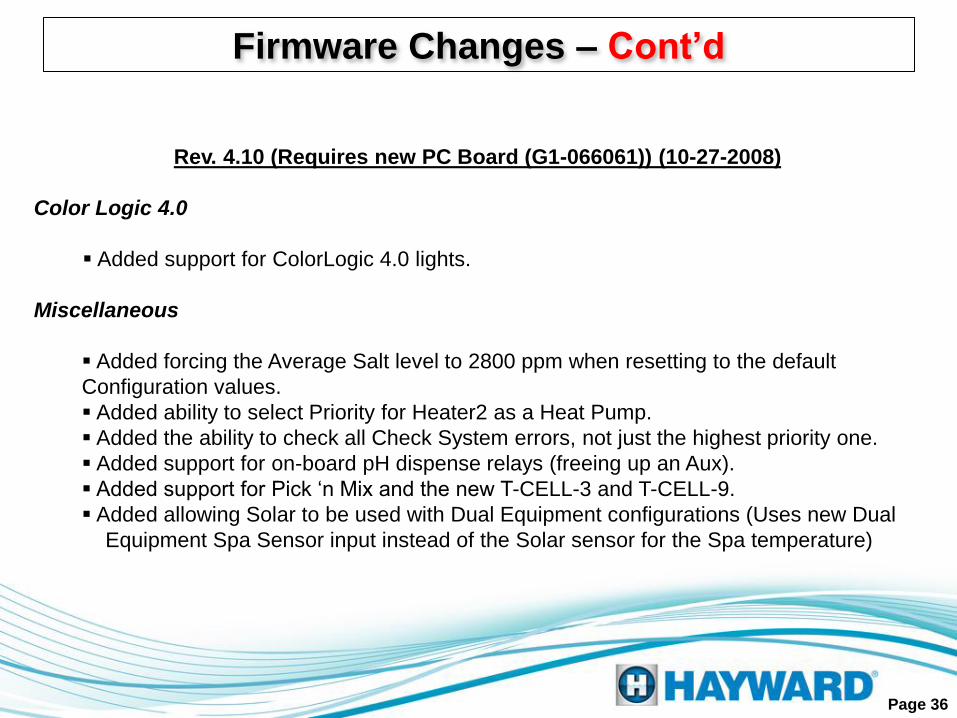
Rev. 4.10 (Requires new PC Board (G1-066061)) (10-27-2008)
Color Logic 4.0
Added support for ColorLogic 4.0 lights.
Miscellaneous
Added forcing the Average Salt level to 2800 ppm when resetting to the default
Configuration values.
Added ability to select Priority for Heater2 as a Heat Pump.
Added the ability to check all Check System errors, not just the highest priority one.
Added support for on-board pH dispense relays (freeing up an Aux).
Added support for Pick ‘n Mix and the new T-CELL-3 and T-CELL-9.
Added allowing Solar to be used with Dual Equipment configurations (Uses new Dual
Equipment Spa Sensor input instead of the Solar sensor for the Spa temperature)
Page 36
Firmware Changes – Cont’d
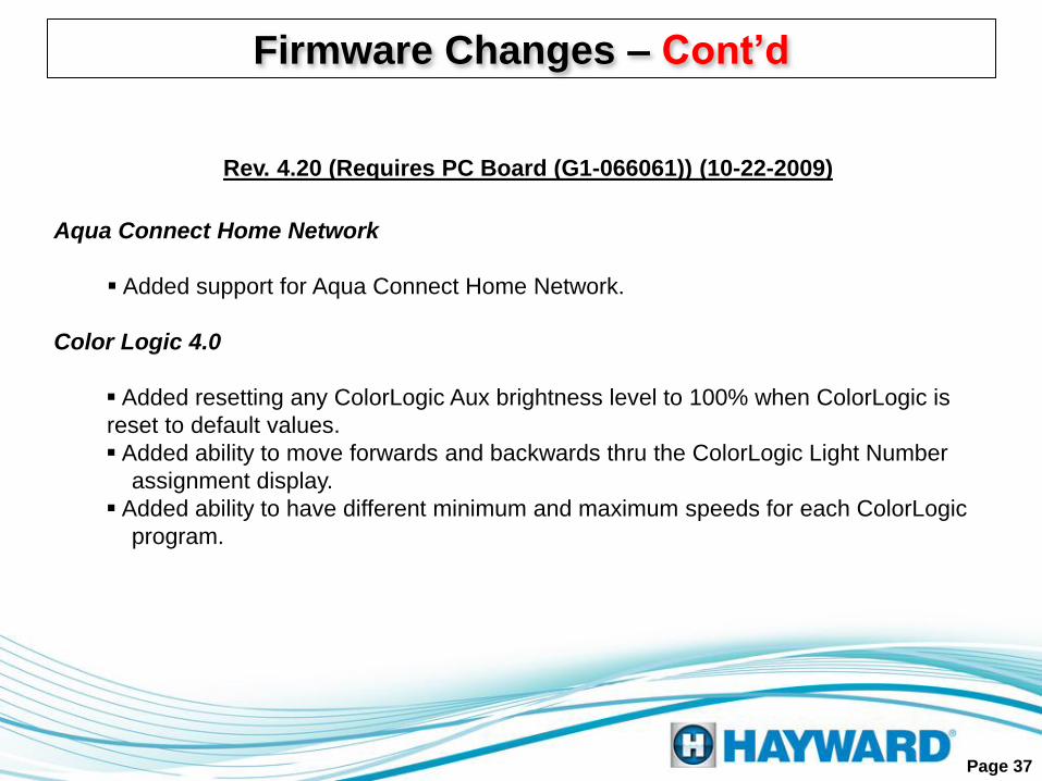
Rev. 4.20 (Requires PC Board (G1-066061)) (10-22-2009)
Aqua Connect Home Network
Added support for Aqua Connect Home Network.
Color Logic 4.0
Added resetting any ColorLogic Aux brightness level to 100% when ColorLogic is
reset to default values.
Added ability to move forwards and backwards thru the ColorLogic Light Number
assignment display.
Added ability to have different minimum and maximum speeds for each ColorLogic
program.
Page 37
Firmware Changes – Cont’d

Rev. 4.30 (Requires PC Board (G1-066061)) (mm-dd-2010)
EcoStar VSP
Added support for up to 8 EcoStar VSPs (Filter, Dual Equipment Spa Filter and up to 6
Lights/Auxes).
Added VSP as a fourth possible Relay Type for each Light/Aux (up to 6, maximum).
Added the ability to select the desired Filter and Spa Filter Speed when manually
switching the filter from Off to On with the +/- keys (similar to setting the Dimmer On
brightness).
Added ability for a speed to be associated with each filter Time clock.
Added Heater Minimum and Spa Filter Freeze Protection speeds when the Dual
Equipment Spa Filter is configured for Variable Speed.
Added the ability to set a Group speed for the Filter, Spa Filter and Lights/Aux VSPs.
Added the ability of selecting % or RPM when displaying the VSP speed to the
Configuration Menu.
Miscellaneous
Added a third and fourth Filter Time clock.
Added special Heater control logic when configured for Spa Only. It now operates more
like the Pool Only configuration.
Page 38
Firmware Changes – Cont’d
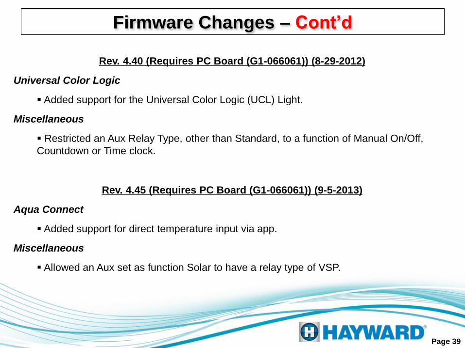
Firmware Changes – Cont’d
Rev. 4.40 (Requires PC Board (G1-066061)) (8-29-2012)
Universal Color Logic
Added support for the Universal Color Logic (UCL) Light.
Miscellaneous
Restricted an Aux Relay Type, other than Standard, to a function of Manual On/Off,
Countdown or Time clock.
Page 39
Rev. 4.45 (Requires PC Board (G1-066061)) (9-5-2013)
Aqua Connect
Added support for direct temperature input via app.
Miscellaneous
Allowed an Aux set as function Solar to have a relay type of VSP.
More on Chlorine Output & Salt Levels 1. The ‘Pool Chlorinator %’ and ‘Spa Chlorinator %’ options under the Setting Menu, control the
level of salt cell operation as a percent of the total operating time of the filter pump. A simple
example is that if the pump/filter is programmed to operate a total of 8 hours in a given day
and the ‘Pool Chlorinator %’ is set to 50% the salt cell will operate (and produce chlorine)
approximately half the time, or 4 hours.
2. The salt level that is calculated (and displayed) in the system is determined from several variables.
It is possible that the displayed salt level can be significantly different from the actual salt level
(when measured in the water with a tester). This can happen as a result of a dirty cell or from a cell
that has began aging. Low salt should always require a cell cleaning first and then an actual meter
measurement of the salt level in the water. If the cell is clean and the level of salt measured in the
water is correct, then the cell has began to age, which results in a lower calculated salt level. This is
an acceptable situation, assuming the level of free chlorine in the pool is appropriate. NEVER add
additional salt in this circumstance. 3. If the free chlorine is not appropriate and the steps in item 2 have been followed and addressed as
needed, then the ‘Pool Chlorinator %’ or ‘Spa Chlorinator %’ needs to be increased in a 25%
increment (for example from 50% to 75%) to allow for the salt cell to operate for a longer period
(% of total operating time) in order to produce a sufficient amount of chlorine as the cell begins
to age. Allow 24 hours and re-test free chlorine. Increase in increments of +10% if required.
Keep in mind this is assuming the chemistry parameters are correct in the water and there is
nothing that is creating a significant chlorine demand.
IMPORTANT !!!
4. Super-chlorinate is an additional option to use in order to ‘catch up’ in chlorine production when
making adjustments to the desired output level. Enable ‘Super Chlorinate’ under the Settings Menu.
Page 40