turck ultrasonic sensors catalog - · pdf fileturck ultrasonics principle of operation the...
TRANSCRIPT

Ultrasonics
Ult
raso
nic
s
Ultrasonics Selection Guide
Embeddable/Nonembeddable Rectangular
Housing 18 mm 18 mm 30 mm
SensingRange
20-70 mm 30-100 mm 300 mm
Pages H9 H11 H13
Embeddable/Nonembeddable Barrels
Housing 30 mm 40 mm
SensingRange
100 mm 100 mm
Pages H15 H15
Phone: 800.894.0412 - Fax: 888.723.4773 - Web: www.clrwtr.com - Email: [email protected]
TURCK
Ultrasonics
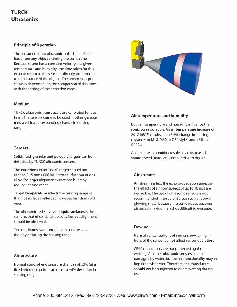
Principle of Operation
The sensor emits an ultrasonic pulse that reflects
back from any object entering the sonic cone.
Because sound has a constant velocity at a given
temperature and humidity, the time taken for this
echo to return to the sensor is directly proportional
to the distance of the object. The sensor’s output
status is dependent on the comparison of this time
with the setting of the detection zone.
Medium
TURCK ultrasonic transducers are calibrated for use
in air. The sensors can also be used in other gaseous
media with a corresponding change in sensing
range.
Targets
Solid, fluid, granular and powdery targets can be
detected by TURCK ultrasonic sensors.
The variations of an “ideal” target should not
exceed 0.15 mm (.006 in). Larger surface variations
allow for larger alignment variations but may
reduce sensing range.
Target temperature affects the sensing range in
that hot surfaces reflect sonic waves less than cold
ones.
The ultrasonic reflectivity of liquid surfaces is the
same as that of solid, flat objects. Correct alignment
should be observed.
Textiles, foams, wool, etc. absorb sonic waves,
thereby reducing the sensing range.
Air pressure
Normal atmospheric pressure changes of ±5% (at a
fixed reference point) can cause a ±6% deviation in
sensing range.
Dewing
Normal concentrations of rain or snow falling in
front of the sensor do not affect sensor operation.
CP40 transducers are not protected against
wetting. All other ultrasonic sensors are not
damaged by water, but correct functionality may be
impaired when wet. Therefore, the transducers
should not be subjected to direct wetting during
use.
Air streams
Air streams affect the echo propagation time, but
the effects of air flow speeds of up to 10 m/s are
negligible. The use of ultrasonic sensors is not
recommended in turbulent areas such as above
glowing metal because the sonic waves become
distorted, making the echos difficult to evaluate.
Air temperature and humidity
Both air temperature and humidity influence the
sonic pulse duration. An air temperature increase of
20°C (68°F) results in a +3.5% change in sensing
distance for M18, M30 or Q30 styles and +8% for
CP40s.
An increase in humidity results in an increased
sound speed (max. 2%) compared with dry air.
Phone: 800.894.0412 - Fax: 888.723.4773 - Web: www.clrwtr.com - Email: [email protected]
Ultrasonics
Ult
raso
nic
s
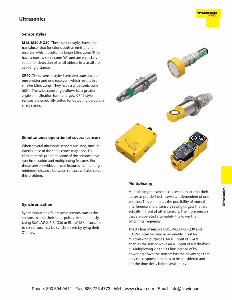
Sensor styles
M18, M30 & Q30: These sensor styles have one
transducer that functions both as emitter and
receiver, which results in a larger blind zone. They
have a narrow sonic cone (6°) and are especially
suited for detection of small objects in a small area
at a long distance.
CP40: These sensor styles have two transducers -
one emitter and one receiver - which results in a
smaller blind zone. They have a wide sonic cone
(60°). The wide cone angle allows for a greater
angle of inclination for the target. CP40 style
sensors are especially suited for detecting objects in
a large area.
Simultaneous operation of several sensors
When several ultrasonic sensors are used, mutual
interference of the sonic cones may arise. To
eliminate this problem, some of the sensors have
synchronization and multiplexing features. For
those sensors without these features maintaining a
minimum distance between sensors will also solve
this problem.
Synchronization
Synchronization of ultrasonic sensors causes the
sensors to emit their sonic pulses simultaneously.
Using RUC...M30, RU..-Q30 or RU..-M18 sensors, up
to six sensors may be synchronized by tying their
X1 lines.
Multiplexing
Multiplexing the sensors causes them to emit their
pulses at pre-defined intervals, independent of one
another. This eliminates the possibility of mutual
interference and of sensors seeing targets that are
actually in front of other sensors. The more sensors
that are operated alternately, the lower the
switching frequency.
The X1 line of sensors RUC..-M30, RU..-Q30 and
RU..-M18 can be used as an enable input for
multiplexing purposes. An X1 input of +24 V
enables the sensor while an X1 input of 0 V disables
it. Multiplexing via the X1 line instead of by
powering down the sensors has the advantage that
only the response time has to be considered and
not the time delay before availability.
Phone: 800.894.0412 - Fax: 888.723.4773 - Web: www.clrwtr.com - Email: [email protected]
TURCK
Ultrasonics
Range adjustments
M30 and CP40 style sensors have two
potentiometers to enable both foreground and
background suppression. Q30 and discrete M18
style sensors have one potentiometer to enable
background suppression only.
Analog M18 sensors have a fixed range.
Sensing ranges given are at nominal conditions,
i.e. Tu = +20°C (68°F) using a standard target,
vertically aligned, with reflective surface
(metal, 1 mm thick).
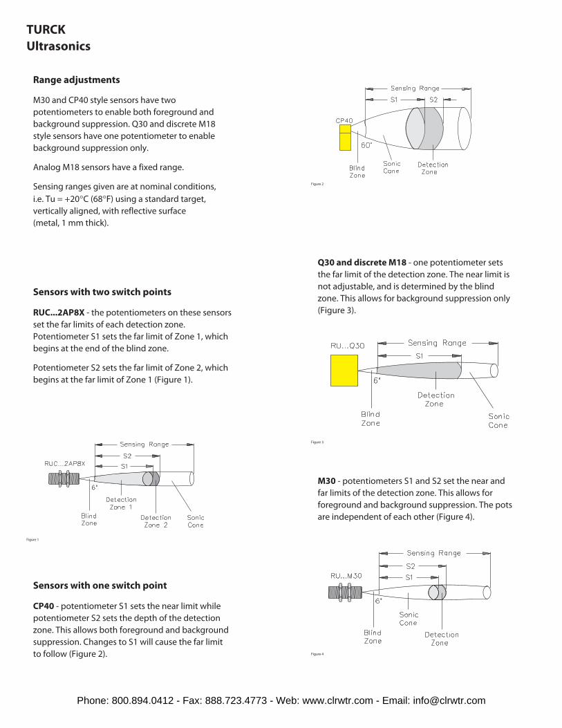
Sensors with two switch points
RUC...2AP8X - the potentiometers on these sensors
set the far limits of each detection zone.
Potentiometer S1 sets the far limit of Zone 1, which
begins at the end of the blind zone.
Potentiometer S2 sets the far limit of Zone 2, which
begins at the far limit of Zone 1 (Figure 1).
Sensors with one switch point
CP40 - potentiometer S1 sets the near limit while
potentiometer S2 sets the depth of the detection
zone. This allows both foreground and background
suppression. Changes to S1 will cause the far limit
to follow (Figure 2).
Q30 and discrete M18 - one potentiometer sets
the far limit of the detection zone. The near limit is
not adjustable, and is determined by the blind
zone. This allows for background suppression only
(Figure 3).
M30 - potentiometers S1 and S2 set the near and
far limits of the detection zone. This allows for
foreground and background suppression. The pots
are independent of each other (Figure 4).
Figure 2
Figure 1
Figure 4
Figure 3
Phone: 800.894.0412 - Fax: 888.723.4773 - Web: www.clrwtr.com - Email: [email protected]
Ultrasonics
Ult
raso
nic
s
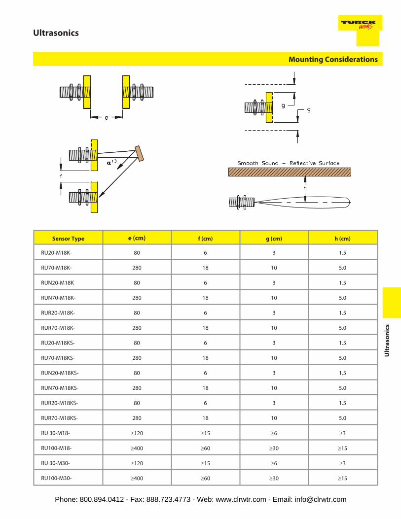
Sensor Type e (cm) f (cm) g (cm) h (cm)
RU20-M18K- 80 6 3 1.5
RU70-M18K- 280 18 10 5.0
RUN20-M18K 80 6 3 1.5
RUN70-M18K- 280 18 10 5.0
RUR20-M18K- 80 6 3 1.5
RUR70-M18K- 280 18 10 5.0
RU20-M18KS- 80 6 3 1.5
RU70-M18KS- 280 18 10 5.0
RUN20-M18KS- 80 6 3 1.5
RUN70-M18KS- 280 18 10 5.0
RUR20-M18KS- 80 6 3 1.5
RUR70-M18KS- 280 18 10 5.0
RU 30-M18- ≥120 ≥15 ≥6 ≥3
RU100-M18- ≥400 ≥60 ≥30 ≥15
RU 30-M30- ≥120 ≥15 ≥6 ≥3
RU100-M30- ≥400 ≥60 ≥30 ≥15
Mounting Considerations
Phone: 800.894.0412 - Fax: 888.723.4773 - Web: www.clrwtr.com - Email: [email protected]

TURCK
Ultrasonics
RUC 130 - M 30 - 2 A P 8 X Wiring Options
RU(C) = Ultrasonic SensorRUN = Ultrasonic SensorRUR = Ultrasonic Sensor
Mounting
Barrel - MetalM = Partial Threading, Chrome Plated Brass
RectangularQ = Metal or Plastic, Various Rectangular Styles
Limit Switch
CP = combiprox®, Plastic Housing, Terminal ChamberBase with Removable Sensor
Housing Style
Rated Operating Distance (cm)
DC:
6 = 10-30 VDC, Polarity Protected, Pulsed SCP8 = 20-30 VDC, Polarity Protected, Pulsed SCPLI = 20-30 VDCLIU= 15-30 VDCLU = 18-30 VDC
Voltage Range
Number of Switch Points
Housing Diameter/Height (mm)
Examples:
Blank = No LEDsX2 = 2 LEDs
Number of LEDs
A = Normally Open (N.O.)LI(LU) = Linear Analog Output Current (LI) or Voltage (LU)LIU = Linear Analog Output (Current and Voltage)LFX = Analog Frequency Output
Output Function
N = NPN Transistor (Current Sinking)P = PNP Transistor (Current Sourcing)
Output
K = Short Barrel LengthS = Side Sensing
Secondary Barrel Modifier
Ultrasonic Sensor Part Number Key
Phone: 800.894.0412 - Fax: 888.723.4773 - Web: www.clrwtr.com - Email: [email protected]

Ultrasonics
Ult
raso
nic
s
Wiring Options
Example:1 = Standard
Number of LEDs
A) Connectorized Sensor
RUC 130-M30-2AP8X- H1 1 5 1
Number of Pins
1 = Straight
Connector / Sensor Transition
H1 = eurofast ®, Metal or Plastic, Male
Connector Family
Phone: 800.894.0412 - Fax: 888.723.4773 - Web: www.clrwtr.com - Email: [email protected]

TURCK
Ultrasonics
Housing Style Part Number ID Number Se
nso
rO
pe
rati
ng
Mo
de
Ra
ted
Op
er.
Dis
tan
ce(c
m)
Ad
just
me
nt
Me
tho
d
So
nic
Co
ne
An
gle
Output
18 mm - Embeddable, Barrel Styleeurofast ® Connection
RUN20-M18K-AP8X-H1141 M1830034 D 5-20 Teach Input 6°
4-Wire DCPNP
RUN70-M18K-AP8X-H1141 M1830035 D 15-70 Teach Input 6°
RUR20-M18K-AP8X-H1141 M1830036 R 7-20 Teach Input 6°
RUR70-M18K-AP8X-H1141 M1830037 R 20-70 Teach Input 6°
RU20-M18K-LFX-H1141 M1830030 D 5-20 Teach Input 6°4-Wire DC
200-800 Hz400-1600 Hz
FrequencyOutput
RU70-M18K-LFX-H1141 M1830031 D 15-70 Teach Input 6°4-Wire DC
150-700 Hz300-1400 Hz
FrequencyOutput
18 mm - Embeddable, Side Sensing, BarrelStyle eurofast connection
RUN20-M18KS-AP8X-H1141 M1830038 D 5-20 Teach Input 6°
4-Wire DCPNP
RUN70-M18KS-AP8X-H1141 M1830039 D 15-70 Teach Input 6°
RUR20-M18KS-AP8X-H1141 M1830040 R 7-20 Teach Input 6°
RUR70-M18KS-AP8X-H1141 M1830041 R 20-70 Teach Input 6°
RU20-M18KS-LFX-H1141 M1830032 D 5-20 Teach Input 6°4-Wire DC
200-800 Hz400-1600 Hz
FrequencyOutput
RU70-M18KS-LFX-H1141 M1830033 D 15-70 Teach Input 6°4-Wire DC
150-700 Hz300-1400 Hz
FrequencyOutput
Sensor operating mode:
D = Diffused
R = Retro-reflective
Adjustment method:
Pot. = Potentiometer
* 4-wire DC sensors can be programmed with a VB2-SP2 programming kit.
Phone: 800.894.0412 - Fax: 888.723.4773 - Web: www.clrwtr.com - Email: [email protected]

Ultrasonics
Ult
raso
nic
s
Voltage Sw
itch
ing
Fre
q. (
Hz)
Co
nti
nu
ou
sLo
ad
Cu
rre
nt
(mA
)O
pe
rati
ng
Te
mp
. (°C
)
Pro
tect
ion
Ho
usi
ng
Tra
nsd
uce
r
Po
we
rLE
D
Ou
tpu
tLE
D
Ma
tin
gC
ord
set
Wir
ing
Dia
gra
m#
Wiring Diagrams
20-30 VDC
10 ≤150 -25 to +70 IP 67 NPB E/PU/PBT N/A YE RK 4.4T-* 1
5 ≤150 -25 to +70 IP 67 NPB E/PU/PBT N/A YE RK 4.4T-* 1
10 ≤150 -25 to +70 IP 67 NPB E/PU/PBT N/A YE RK 4.4T-* 1
5 ≤150 -25 to +70 IP 67 NPB E/PU/PBT N/A YE RK 4.4T-* 1
20-30 VDC
N/A ≤150 -25 to +70 IP 67 NPB E/PU/PBT N/A YE RK 4.4T-* 2
20-30 VDC
N/A ≤150 -25 to +70 IP 67 NPB E/PU/PBT N/A YE RK 4.4T-* 2
20-30 VDC
10 ≤150 -25 to +70 IP 67 NPB E/PU/PBT N/A YE RK 4.4T-* 1
5 ≤150 -25 to +70 IP 67 NPB E/PU/PBT N/A YE RK 4.4T-* 1
10 ≤150 -25 to +70 IP 67 NPB E/PU/PBT N/A YE RK 4.4T-* 1
5 ≤150 -25 to +70 IP 67 NPB E/PU/PBT N/A YE RK 4.4T-* 1
20-30 VDC
N/A ≤150 -25 to +70 IP 67 NPB E/PU/PBT N/A YE RK 4.4T-* 2
20-30 VDC
N/A ≤150 -25 to +70 IP 67 NPB E/PU/PBT N/A YE RK 4.4T-* 2
* Length in meters.
Diagram 2
Diagram 1
Phone: 800.894.0412 - Fax: 888.723.4773 - Web: www.clrwtr.com - Email: [email protected]
TURCK
Ultrasonics
Housing Style Part Number ID Number Se
nso
rO
pe
rati
ng
Mo
de
Ra
ted
Op
er.
Dis
tan
ce(c
m)
Ad
just
me
nt
Me
tho
dS
on
icC
on
eA
ng
le
Output
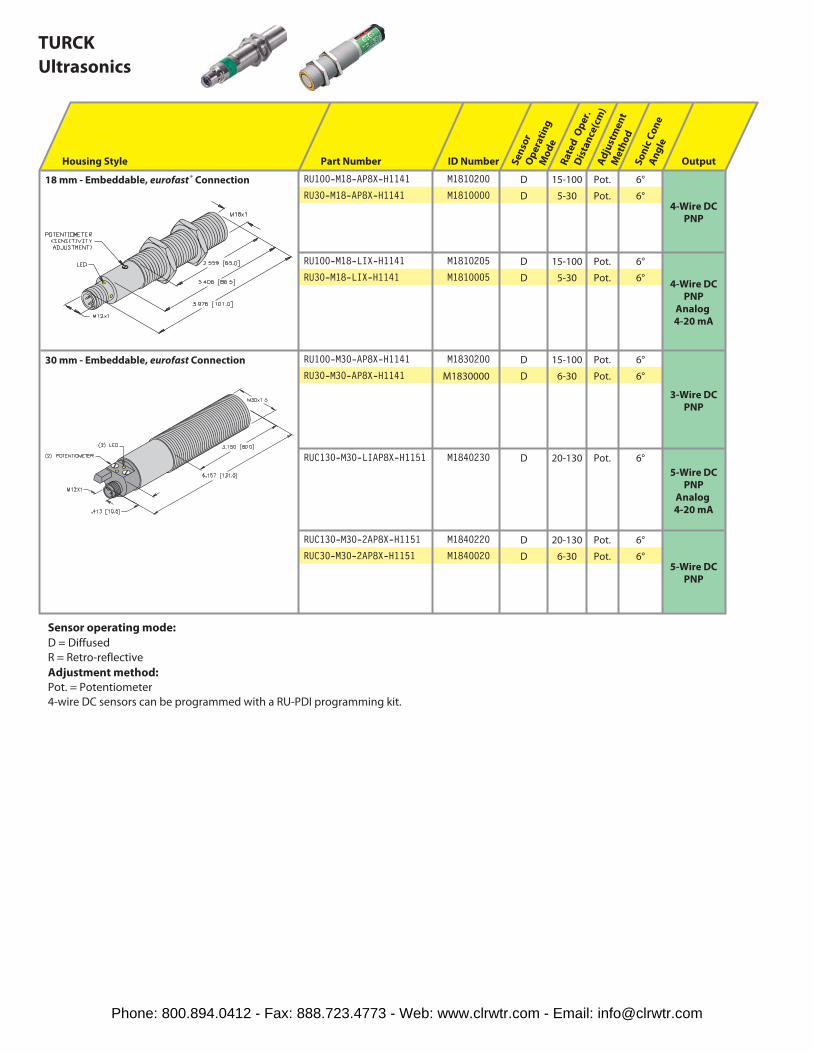
18 mm - Embeddable, eurofast ® Connection RU100-M18-AP8X-H1141 M1810200 D 15-100 Pot. 6°
4-Wire DCPNP
RU30-M18-AP8X-H1141 M1810000 D 5-30 Pot. 6°
RU100-M18-LIX-H1141 M1810205 D 15-100 Pot. 6°
4-Wire DCPNP
Analog4-20 mA
RU30-M18-LIX-H1141 M1810005 D 5-30 Pot. 6°
30 mm - Embeddable, eurofast Connection RU100-M30-AP8X-H1141 M1830200 D 15-100 Pot. 6°
3-Wire DCPNP
RU30-M30-AP8X-H1141 M1830000 D 6-30 Pot. 6°
RUC130-M30-LIAP8X-H1151 M1840230 D 20-130 Pot. 6°
5-Wire DCPNP
Analog4-20 mA
RUC130-M30-2AP8X-H1151 M1840220 D 20-130 Pot. 6°
5-Wire DCPNP
RUC30-M30-2AP8X-H1151 M1840020 D 6-30 Pot. 6°
Sensor operating mode:
D = Diffused
R = Retro-reflective
Adjustment method:
Pot. = Potentiometer
4-wire DC sensors can be programmed with a RU-PDI programming kit.
Phone: 800.894.0412 - Fax: 888.723.4773 - Web: www.clrwtr.com - Email: [email protected]
Ultrasonics
Ult
raso
nic
s
Voltage Sw
itch
ing
Fre
q. (
Hz)
Co
nti
nu
ou
sLo
ad
Cu
rre
nt
(mA
)
Op
era
tin
gT
em
p. (
°C)
Pro
tect
ion
Ho
usi
ng
Tra
nsd
uce
r
Po
we
rLE
DO
utp
ut
LED
Ma
tin
gC
ord
set
Wir
ing
Dia
gra
m#
Wiring Diagrams
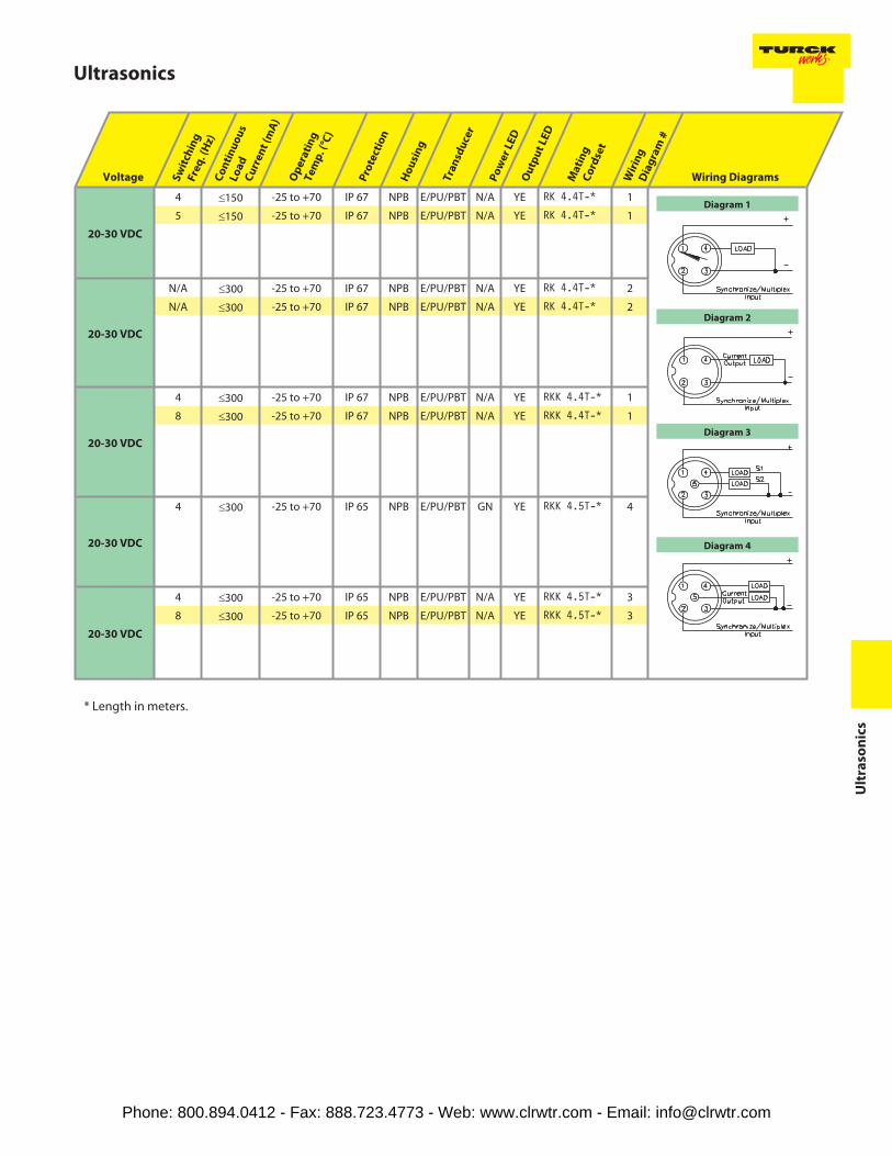
20-30 VDC
4 ≤150 -25 to +70 IP 67 NPB E/PU/PBT N/A YE RK 4.4T-* 1
5 ≤150 -25 to +70 IP 67 NPB E/PU/PBT N/A YE RK 4.4T-* 1
20-30 VDC
N/A ≤300 -25 to +70 IP 67 NPB E/PU/PBT N/A YE RK 4.4T-* 2
N/A ≤300 -25 to +70 IP 67 NPB E/PU/PBT N/A YE RK 4.4T-* 2
20-30 VDC
4 ≤300 -25 to +70 IP 67 NPB E/PU/PBT N/A YE RKK 4.4T-* 1
8 ≤300 -25 to +70 IP 67 NPB E/PU/PBT N/A YE RKK 4.4T-* 1
20-30 VDC
4 ≤300 -25 to +70 IP 65 NPB E/PU/PBT GN YE RKK 4.5T-* 4
20-30 VDC
4 ≤300 -25 to +70 IP 65 NPB E/PU/PBT N/A YE RKK 4.5T-* 3
8 ≤300 -25 to +70 IP 65 NPB E/PU/PBT N/A YE RKK 4.5T-* 3
* Length in meters.
Diagram 3
Diagram 1
Diagram 2
Diagram 4
Phone: 800.894.0412 - Fax: 888.723.4773 - Web: www.clrwtr.com - Email: [email protected]

TURCK
Ultrasonics
Housing Style Part Number ID Number Se
nso
rO
pe
rati
ng
Mo
de
Ra
ted
Op
er.
Dis
tan
ce(c
m)
Ad
just
me
nt
Me
tho
dS
on
icC
on
eA
ng
le
Output
47 mm - Embeddable, eurofast ® Connection RUC300-M3047-AP8X-H1141 M1840400 D 40-300 Pot. 6°
4-Wire DCPNP
RUC300-M3047-2AP8X-H1151 M1840420 D 40-300 Pot. 6°
5-Wire DCPNP
Sensor operating mode:
D = Diffused
R = Retro-reflective
Adjustment method:
Pot. = Potentiometer
4-wire DC sensors can be programmed with a RU-PDI programming kit.
Phone: 800.894.0412 - Fax: 888.723.4773 - Web: www.clrwtr.com - Email: [email protected]
Ultrasonics
Ult
raso
nic
s
Voltage Sw
itch
ing
Fre
q. (
Hz)
Co
nti
nu
ou
sLo
ad
Cu
rre
nt
(mA
)
Op
era
tin
gT
em
p. (
°C)
Pro
tect
ion
Ho
usi
ng
Tra
nsd
uce
r
Po
we
rLE
DO
utp
ut
LED
Ma
tin
gC
ord
set
Wir
ing
Dia
gra
m#
Wiring Diagrams
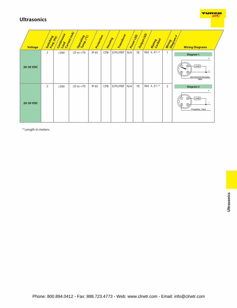
20-30 VDC
2 ≤300 -25 to +70 IP 65 CPB E/PU/PBT N/A YE RKK 4.4T-* 1
20-30 VDC
2 ≤300 -25 to +70 IP 65 CPB E/PU/PBT N/A YE RKK 4.5T-* 2
* Length in meters.
Diagram 1
Diagram 2
Phone: 800.894.0412 - Fax: 888.723.4773 - Web: www.clrwtr.com - Email: [email protected]

TURCK
Ultrasonics
Housing Style Part Number ID Number Se
nso
rO
pe
rati
ng
Mo
de
Ra
ted
Op
er.
Dis
tan
ce(c
m)
Ad
just
me
nt
Me
tho
d
So
nic
Co
ne
An
gle
Output
30 mm - Embeddable, Rectangular,eurofast ® Quick Disconnect
RU100-Q30-AP8X-H1141 M1820200 D 20-100 Pot. 6°
4-Wire DCPNP
RU100-Q30-LUX-H1141 M1820205 D 20-100 Pot. 6°
4-WireAnalog0-10 V
Voltage
40 mm - Embeddable, Rectangular,Terminal Chamber
RU100-CP40-AP6X2 W/ESD M1610200 D 5-180 Pot. 60°
3-Wire DCPNP
Sensor operating mode:
D = Diffused
R = Retro-reflective
Phone: 800.894.0412 - Fax: 888.723.4773 - Web: www.clrwtr.com - Email: [email protected]

Ultrasonics
Ult
raso
nic
s
Voltage Sw
itch
ing
Fre
q. (
Hz)
Co
nti
nu
ou
sLo
ad
Cu
rre
nt
(mA
)
Op
era
tin
gT
em
p. (
°C)
Pro
tect
ion
Ho
usi
ng
Tra
nsd
uce
r
Po
we
rLE
D
Ou
tpu
tLE
D
Ma
tin
gC
ord
set/
Ca
ble
Wir
ing
Dia
gra
m#
Wiring Diagrams
18-35 VDC
5 ≤100 -25 to +70 IP 65 Crastin EPR N/A YE RKK 4.4T-* 1
18-35 VDC
N/A ≤100 -25 to +70 IP 65 Crastin EPR N/A YE RKK 4.4T-* 2
10-30 VDC
3 ≤200 -25 to +70 IP 67 PBT EPR GN YE - - - - 3
* Length in meters.
Diagram 1
Diagram 2
Diagram 3
Phone: 800.894.0412 - Fax: 888.723.4773 - Web: www.clrwtr.com - Email: [email protected]