turcon® r p ® ip l i r a v information in this brochure is intended to be for general reference...
TRANSCRIPT

Trelleborg Se AlINg SolUTIoNS
yoUr pArTNer for Se AlINg TechNology
Turcon®Turcon®TurconVarilipTurconVarilipTurcon ®Varilip®Varilip PDR ® PDR ®

2 • TRELLEBORG SEALING SOLUTIONS Latest information available at www.tss.trelleborg.com • Edition May 2018
ISO 9001:2008 ISO/TS 16949:2009
Your Partner for Sealing Technology
Trelleborg Sealing Solutions is a major international developer, manufacturer and supplier of seals, bearings and molded components in polymers. We are uniquely placed to offer dedicated design and development from our market-leading product and material portfolio: a one-stop-shop providing the best in elastomer, silicone, thermoplastic, PTFE and composite technologies for applications in aerospace, industrial and automotive industries.
With 50 years of experience, Trelleborg Sealing Solutions engineers support customers with design, prototyping, production, test and installation using state-of-the-art design tools. An international network of over 70 facilities worldwide includes over 20 manu- facturing sites, strategically-positioned research and development centers, including materials and development laboratories and locations specializing in design and applications.
Developing and formulating materials in-house, we utilize the resource of our material database, including over 2,000
proprietary compounds and a range of unique products.Trelleborg Sealing Solutions fulfills challenging service requirements, supplying standard parts in volume or a single custom-manufactured component, through our integrated logistical support, which effectively delivers over 40,000 sealing products to customers worldwide.
Facilities are certified to ISO 9001:2008 and ISO/TS 16949:2009. Trelleborg Sealing Solutions is backed by the experience and resources of Trelleborg Group, one of the world’s foremost experts in polymer technology.
The information in this brochure is intended to be for general reference purposes only and is not intended to be a specific recommendation for any individual application.
The application limits for pressure, temperature, speed and media given are maximum values determined in laboratory conditions. In application, due to the interaction of operating
parameters, maximum values may not be achieved. It is vital therefore, that customers satisfy themselves as to the suitability of product and material for each of their individual
applications. Any reliance on information is therefore at the user‘s own risk. In no event will Trelleborg Sealing Solutions be liable for any loss, damage, claim or expense directly
or indirectly arising or resulting from the use of any information provided in this brochure. While every effort is made to ensure the accuracy of information contained herewith,
Trelleborg Sealing Solutions cannot warrant the accuracy or completeness of information.
To obtain the best recommendation for a specific application, please contact your local Trelleborg Sealing Solutions marketing company.
This edition supersedes all previous brochures. This brochure or any part of it may not be reproduced without permission.
® All trademarks are the property of Trelleborg Group. The turquoise color is a registered trademark of Trelleborg Group. © 2018, Trelleborg Group. All rights reserved.
TSS_Turcon_Varilip_PDR_2018_Cover.indd 2 14.05.2018 13:26:27
Turcon®Varilip®PDR
TRELLEBORG SEALING SOLUTIONS • 3Latest information available at www.tss.trelleborg.com • Edition May 2018
4 Introduction
4 Description
5 Turcon®Varilip®PDR Product Range
7 Materials
9 Technical Data
14 Design Guidelines
16 Installation Requirements
16 Storage
17 Fitting Instructions
18 Installation Recommendations
19 Turcon®Varilip®PDR Size Ranges
29 Ordering Information
31 Engineering Action Request
Contents
TSS_Turcon_Varilip_PDR_2018.indd 3 14.05.2018 13:02:26

Turcon®Varilip®PDR
4 • TRELLEBORG SEALING SOLUTIONS Latest information available at www.tss.trelleborg.com • Edition May 2018
� IntroductionTurcon®Varilip®PDR rotary shaft seals extend the boundaries imposed by elastomer radial shaft seals by utilizing advanced materials and design techniques to provide the optimum sealing performance for each application. The outcome is a superior sealing solution, which retains a compact seal envelope.
Turcon®Varilip®PDR rotary shaft seals can be used to replace standard elastomeric rotary shaft seals which have a limited application range with respect to temperature, surface speed, media compatibility, pressure or a combination of these due to the inherent limitations of many elastomer grades.
Turcon®Varilip®PDR rotary shaft seals are characterized in particular by the low friction of the Turcon®lip material and their stick-slip-free running, reducing temperature generation and permitting higher surface speeds.
Turcon®has the characteristic of inherent memory, whereby a distorted Turcon®component will attempt to recover to the profile it had during the manufacturing process. This feature is used to help provide the necessary radial loading of the sealing lip onto the shaft, therefore negating the requirement for the energizing spring present in elastomeric seal designs.
Turcon®Varilip®PDR seals are typically the first choice for challenging application conditions. Characteristically, they can be found in applications such as vacuum pumps where both chemical compatibility and ever-increasing performance demands create harsh environments for sealing systems. Turcon®Varilip®PDR seals are also used in compressors where the requirements are long life and the ability to cope with intermittent shaft rotation.
Other market segments where Turcon®Varilip®PDR seals are used include: Chemical process industries, Aerospace, Marine, Motorsport, and Automotive electric drivetrains.
Electrically conductive Turcon®grades are available as special designs for applications where shaft grounding is required to dissipate electrical charge.
Friction optimized versions of Turcon®Varilip®PDR seals are also available as special designs. This design is particularly suited for high peripheral shaft speed and low lubrication levels (mist or splash).
� DescriptionTurcon®Varilip®PDR seals are constructed from only two parts – a precision manufactured metal body and a mechanically retained Turcon®sealing element. Unlike seals with pressed metal cases, a gasket is not required to provide sealing between the lip and casing. This is provided by the mechanical retention of the lip, thus improving both the chemical resistance and temperature range of the sealing system.
The mechanical retention of the Turcon®provides a robust product which also eliminates the process of bonding the Turcon®to a metal or elastomer substrate.
Machinedmetal body
Turcon®
Sealing element
Figure 1: Turcon®Varilip®PDR
Where required, the Turcon®Varilip®PDR seal is available with a hydrodynamic feature on the Turcon®sealing lip. This provides a positive displacement of the fluid as a result of the shaft rotation to give improved sealing in applications where the shaft only rotates in a single direction. The feature also increases the flexibility of the lip, which allows a wider contact band between the Turcon®lip and the shaft which helps to reduce shaft load and associated friction-related temperature generation.
TSS_Turcon_Varilip_PDR_2018.indd 4 14.05.2018 13:02:27
Turcon®Varilip®PDR
TRELLEBORG SEALING SOLUTIONS • 5Latest information available at www.tss.trelleborg.com • Edition May 2018
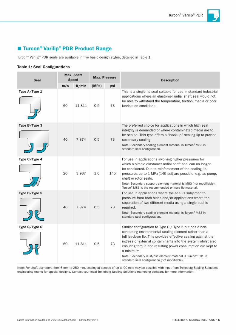
� Turcon®Varilip®PDR Product RangeTurcon®Varilip®PDR seals are available in five basic design styles, detailed in Table 1.
Table 1: Seal Configurations
SealMax. Shaft
SpeedMax. Pressure
Description
m/s ft/min (MPa) psi
Type A/Type 1
Type A / Type 1
Type B / Type 3
Type C / Type 4
Type D / Type 5
Type G / Type 6
SealMax. Shaft
SpeedMax.
Pressurem/s ft/min
60 11,811 0.5 73
40 7,874 0.5 73
20 3,937 1.0 145
40 7,874 0.5 73
60 11,811 0.5 73
This is a single lip seal suitable for use in standard industrial applica-tions where an elastomer radial shaft seal would not be able to withstand the temperature, friction, media or poor lubrication condi-tions.
The preferred choice for applications in which high seal integrity is demanded or where contaminated media are to be sealed. This type offers a back-up sealing lip to provide secondary sealing.
Note: Secondary sealing element material is Turcon® M83 in standard seal configuration.
For use in applications involving higher pressures for which a simple elastomer radial shaft seal can no longer be considered. Due to reinforcement of the sealing lip, pressures up to 1 MPa (145 psi) are possible, e.g. as pump, shaft or rotor seals.
Note: Secondary support element material is M83 (not modifiable). Turcon® M83 is the recommended primary lip material.
For use in applications where the seal is subjected to pressure from both sides and/or applications where the seperation of two different media using a single seal is required.
Note: Secondary sealing element material is Turcon® M83 in standard seal configuration.
Similar configuration to Type D / Type 5 but has a non-contacting environmental sealing element rather than a full lay-down lip. This provides effective sealing against the ingress of external contami-nants into the system whilst also ensuring torque and resulting power consumption are kept to a minimum.
Note: Secondary dust/dirt element material is Turcon® T01 in standard seal configuration (not modifiable).
DescriptionMPa psi
60 11,811 0.5 73
This is a single lip seal suitable for use in standard industrial applications where an elastomer radial shaft seal would not be able to withstand the temperature, friction, media or poor lubrication conditions.
Type B/Type 3Type A / Type 1
Type B / Type 3
Type C / Type 4
Type D / Type 5
Type G / Type 6
SealMax. Shaft
SpeedMax.
Pressurem/s ft/min
60 11,811 0.5 73
40 7,874 0.5 73
20 3,937 1.0 145
40 7,874 0.5 73
60 11,811 0.5 73
This is a single lip seal suitable for use in standard industrial applica-tions where an elastomer radial shaft seal would not be able to withstand the temperature, friction, media or poor lubrication condi-tions.
The preferred choice for applications in which high seal integrity is demanded or where contaminated media are to be sealed. This type offers a back-up sealing lip to provide secondary sealing.
Note: Secondary sealing element material is Turcon® M83 in standard seal configuration.
For use in applications involving higher pressures for which a simple elastomer radial shaft seal can no longer be considered. Due to reinforcement of the sealing lip, pressures up to 1 MPa (145 psi) are possible, e.g. as pump, shaft or rotor seals.
Note: Secondary support element material is M83 (not modifiable). Turcon® M83 is the recommended primary lip material.
For use in applications where the seal is subjected to pressure from both sides and/or applications where the seperation of two different media using a single seal is required.
Note: Secondary sealing element material is Turcon® M83 in standard seal configuration.
Similar configuration to Type D / Type 5 but has a non-contacting environmental sealing element rather than a full lay-down lip. This provides effective sealing against the ingress of external contami-nants into the system whilst also ensuring torque and resulting power consumption are kept to a minimum.
Note: Secondary dust/dirt element material is Turcon® T01 in standard seal configuration (not modifiable).
DescriptionMPa psi
40 7,874 0.5 73
The preferred choice for applications in which high seal integrity is demanded or where contaminated media are to be sealed. This type offers a “back-up” sealing lip to provide secondary sealing.Note: Secondary sealing element material is Turcon®M83 in standard seal configuration.
Type C/Type 4
Type A / Type 1
Type B / Type 3
Type C / Type 4
Type D / Type 5
Type G / Type 6
SealMax. Shaft
SpeedMax.
Pressurem/s ft/min
60 11,811 0.5 73
40 7,874 0.5 73
20 3,937 1.0 145
40 7,874 0.5 73
60 11,811 0.5 73
This is a single lip seal suitable for use in standard industrial applica-tions where an elastomer radial shaft seal would not be able to withstand the temperature, friction, media or poor lubrication condi-tions.
The preferred choice for applications in which high seal integrity is demanded or where contaminated media are to be sealed. This type offers a back-up sealing lip to provide secondary sealing.
Note: Secondary sealing element material is Turcon® M83 in standard seal configuration.
For use in applications involving higher pressures for which a simple elastomer radial shaft seal can no longer be considered. Due to reinforcement of the sealing lip, pressures up to 1 MPa (145 psi) are possible, e.g. as pump, shaft or rotor seals.
Note: Secondary support element material is M83 (not modifiable). Turcon® M83 is the recommended primary lip material.
For use in applications where the seal is subjected to pressure from both sides and/or applications where the seperation of two different media using a single seal is required.
Note: Secondary sealing element material is Turcon® M83 in standard seal configuration.
Similar configuration to Type D / Type 5 but has a non-contacting environmental sealing element rather than a full lay-down lip. This provides effective sealing against the ingress of external contami-nants into the system whilst also ensuring torque and resulting power consumption are kept to a minimum.
Note: Secondary dust/dirt element material is Turcon® T01 in standard seal configuration (not modifiable).
DescriptionMPa psi
20 3,937 1.0 145
For use in applications involving higher pressures for which a simple elastomer radial shaft seal can no longer be considered. Due to reinforcement of the sealing lip, pressures up to 1 MPa (145 psi) are possible, e.g. as pump, shaft or rotor seals.Note: Secondary support element material is M83 (not modifiable). Turcon®M83 is the recommended primary lip material.
Type D/Type 5
Type A / Type 1
Type B / Type 3
Type C / Type 4
Type D / Type 5
Type G / Type 6
SealMax. Shaft
SpeedMax.
Pressurem/s ft/min
60 11,811 0.5 73
40 7,874 0.5 73
20 3,937 1.0 145
40 7,874 0.5 73
60 11,811 0.5 73
This is a single lip seal suitable for use in standard industrial applica-tions where an elastomer radial shaft seal would not be able to withstand the temperature, friction, media or poor lubrication condi-tions.
The preferred choice for applications in which high seal integrity is demanded or where contaminated media are to be sealed. This type offers a back-up sealing lip to provide secondary sealing.
Note: Secondary sealing element material is Turcon® M83 in standard seal configuration.
For use in applications involving higher pressures for which a simple elastomer radial shaft seal can no longer be considered. Due to reinforcement of the sealing lip, pressures up to 1 MPa (145 psi) are possible, e.g. as pump, shaft or rotor seals.
Note: Secondary support element material is M83 (not modifiable). Turcon® M83 is the recommended primary lip material.
For use in applications where the seal is subjected to pressure from both sides and/or applications where the seperation of two different media using a single seal is required.
Note: Secondary sealing element material is Turcon® M83 in standard seal configuration.
Similar configuration to Type D / Type 5 but has a non-contacting environmental sealing element rather than a full lay-down lip. This provides effective sealing against the ingress of external contami-nants into the system whilst also ensuring torque and resulting power consumption are kept to a minimum.
Note: Secondary dust/dirt element material is Turcon® T01 in standard seal configuration (not modifiable).
DescriptionMPa psi
40 7,874 0.5 73
For use in applications where the seal is subjected to pressure from both sides and/or applications where the separation of two different media using a single seal is required.Note: Secondary sealing element material is Turcon®M83 in standard seal configuration.
Type G/Type 6
Type A / Type 1
Type B / Type 3
Type C / Type 4
Type D / Type 5
Type G / Type 6
SealMax. Shaft
SpeedMax.
Pressurem/s ft/min
60 11,811 0.5 73
40 7,874 0.5 73
20 3,937 1.0 145
40 7,874 0.5 73
60 11,811 0.5 73
This is a single lip seal suitable for use in standard industrial applica-tions where an elastomer radial shaft seal would not be able to withstand the temperature, friction, media or poor lubrication condi-tions.
The preferred choice for applications in which high seal integrity is demanded or where contaminated media are to be sealed. This type offers a back-up sealing lip to provide secondary sealing.
Note: Secondary sealing element material is Turcon® M83 in standard seal configuration.
For use in applications involving higher pressures for which a simple elastomer radial shaft seal can no longer be considered. Due to reinforcement of the sealing lip, pressures up to 1 MPa (145 psi) are possible, e.g. as pump, shaft or rotor seals.
Note: Secondary support element material is M83 (not modifiable). Turcon® M83 is the recommended primary lip material.
For use in applications where the seal is subjected to pressure from both sides and/or applications where the seperation of two different media using a single seal is required.
Note: Secondary sealing element material is Turcon® M83 in standard seal configuration.
Similar configuration to Type D / Type 5 but has a non-contacting environmental sealing element rather than a full lay-down lip. This provides effective sealing against the ingress of external contami-nants into the system whilst also ensuring torque and resulting power consumption are kept to a minimum.
Note: Secondary dust/dirt element material is Turcon® T01 in standard seal configuration (not modifiable).
DescriptionMPa psi
60 11,811 0.5 73
Similar configuration to Type D / Type 5 but has a non-contacting environmental sealing element rather than a full lay-down lip. This provides effective sealing against the ingress of external contaminants into the system whilst also ensuring torque and resulting power consumption are kept to a minimum.Note: Secondary dust/dirt element material is Turcon®T01 in standard seal configuration (not modifiable).
Note: For shaft diameters from 6 mm to 250 mm, sealing at speeds of up to 90 m/s may be possible with input from Trelleborg Sealing Solutions engineering teams for special designs. Contact your local Trelleborg Sealing Solutions marketing company for more information.
TSS_Turcon_Varilip_PDR_2018.indd 5 14.05.2018 13:02:27

Turcon®Varilip®PDR
6 • TRELLEBORG SEALING SOLUTIONS Latest information available at www.tss.trelleborg.com • Edition May 2018
TuRCOn®VARIlIP®PDR: SPECIAl DESIGnS
Inner case
Outer case
Elastomericgasket
Fluid
Turcon® sealing lip
Turcon®
dust lip
Figure 2: Clamped Design. Suited to high volume applications with excessive housing tolerance.
Fluid
Machined or cast metal body O-Ring
Turcon® sealing lip
Figure 3: O-Ring Design. For low interference fits in the housing. Housing surface finish > 0.8 µm Ra or particularly searching media control.
Alongside the standard range, Turcon®Varilip®PDR seals are available as special designs to satisfy the demands of specific applications and can therefore accommodate non-standard
housing and shaft sizes. Figure 2 to Figure 7 show some of the special designs available.
Figure 4: Sealing against the Bore. For applications where the running surface is located on the housing.
Figure 5: Fluid Transfer. Injection ports enable the transfer of fluid between the housing and the shaft.
Figure 6: End Plate. Allows for simple assembly/disassembly of the seal.
Figure 7: Elastomer/Turcon®Hybrid. This combination utilizes the best attributes of both a Radial Oil Seal and the Turcon®Varilip®PDR.
TSS_Turcon_Varilip_PDR_2018.indd 6 14.05.2018 13:02:28
Turcon®Varilip®PDR
TRELLEBORG SEALING SOLUTIONS • 7Latest information available at www.tss.trelleborg.com • Edition May 2018
� Materials
SEAlInG lIP
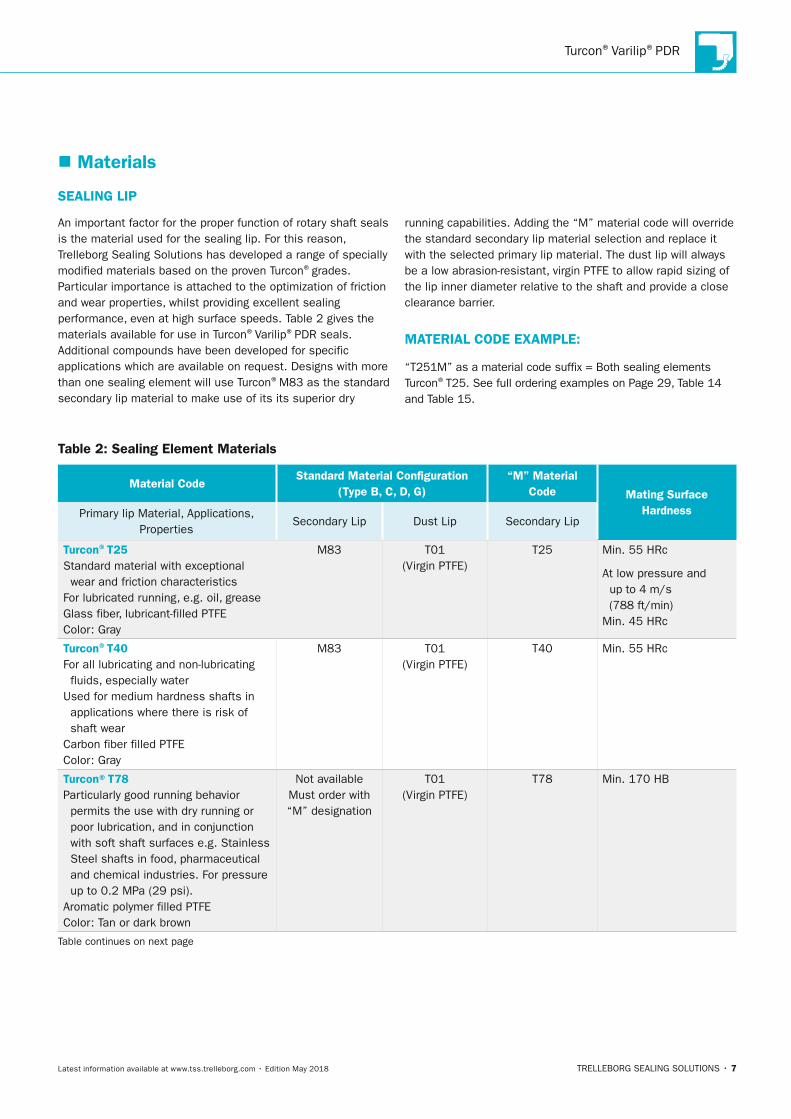
An important factor for the proper function of rotary shaft seals is the material used for the sealing lip. For this reason, Trelleborg Sealing Solutions has developed a range of specially modified materials based on the proven Turcon®grades. Particular importance is attached to the optimization of friction and wear properties, whilst providing excellent sealing performance, even at high surface speeds. Table 2 gives the materials available for use in Turcon®Varilip®PDR seals.Additional compounds have been developed for specific applications which are available on request. Designs with more than one sealing element will use Turcon®M83 as the standard secondary lip material to make use of its its superior dry
running capabilities. Adding the “M” material code will override the standard secondary lip material selection and replace it with the selected primary lip material. The dust lip will always be a low abrasion-resistant, virgin PTFE to allow rapid sizing of the lip inner diameter relative to the shaft and provide a close clearance barrier.
MATERIAl CODE ExAMPlE:
“T251M” as a material code suffix = Both sealing elements Turcon®T25. See full ordering examples on Page 29, Table 14 and Table 15.
Table 2: Sealing Element Materials
Material CodeStandard Material Configuration
(Type B, C, D, G)“M” Material
Code Mating Surface HardnessPrimary lip Material, Applications,
PropertiesSecondary Lip Dust Lip Secondary Lip
Turcon®T25Standard material with exceptional wear and friction characteristicsFor lubricated running, e.g. oil, greaseGlass fiber, lubricant-filled PTFEColor: Gray
M83 T01(Virgin PTFE)
T25 Min. 55 HRc
At low pressure and up to 4 m/s (788 ft/min) Min. 45 HRc
Turcon®T40For all lubricating and non-lubricating fluids, especially waterUsed for medium hardness shafts in applications where there is risk of shaft wearCarbon fiber filled PTFEColor: Gray
M83 T01(Virgin PTFE)
T40 Min. 55 HRc
Turcon®T78Particularly good running behavior permits the use with dry running or poor lubrication, and in conjunction with soft shaft surfaces e.g. Stainless Steel shafts in food, pharmaceutical and chemical industries. For pressure up to 0.2 MPa (29 psi).Aromatic polymer filled PTFEColor: Tan or dark brown
Not available Must order with “M” designation
T01(Virgin PTFE)
T78 Min. 170 HB
Table continues on next page
TSS_Turcon_Varilip_PDR_2018.indd 7 14.05.2018 13:02:28

Turcon®Varilip®PDR
8 • TRELLEBORG SEALING SOLUTIONS Latest information available at www.tss.trelleborg.com • Edition May 2018
METAl BODy
Turcon®Varilip®PDR seals are available as standard using the materials shown in Table 3. Other specialised materials are available on request.
Table 3: Metal Body Materials
Code Material
1 Stainless Steel 304
2 Stainless Steel 316
3 Unavailable
4 Mild Steel (Zinc Plated)
5 Aluminum (Industrial)
Material CodeStandard Material Configuration
(Type B, C, D, G)“M” Material
Code Mating Surface HardnessPrimary lip Material, Applications,
PropertiesSecondary Lip Dust Lip Secondary Lip
Turcon®M83Specially designed for dry-running applications. Particularly good results in applications for the semiconductor industry. Can also be used lubricatedGlass fiber and pigment filled PTFEColor: Yellow
M83 T01(Virgin PTFE)
N/A Min. 60 HRc
Turcon®MF5Specially designed for dry-running applications. Can also be used lubricated. For food contact serviceGlass fiber-filled PTFEColor: White
Not availableMust order with “M” designation
MF1(Virgin PTFE)
MF5 Min. 60 HRc
Turcon®MF6Especially suited for low pressure rotary applications and running against soft surfaces. For food contact servicePEEK-filled PTFEColor: Tan
Not available Must order with “M” designation
MF1(Virgin PTFE)
MF6 Min. 170 HB
TSS_Turcon_Varilip_PDR_2018.indd 8 14.05.2018 13:02:28
Turcon®Varilip®PDR
TRELLEBORG SEALING SOLUTIONS • 9Latest information available at www.tss.trelleborg.com • Edition May 2018
� Technical Data
SPEED
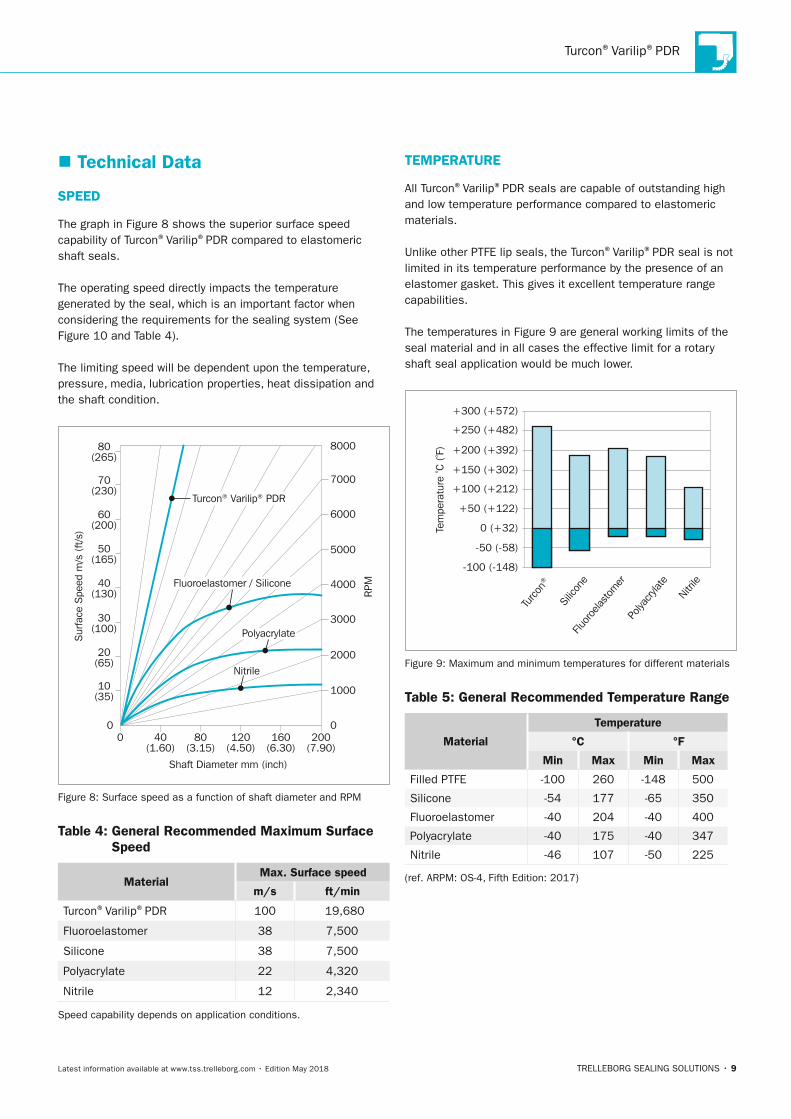
The graph in Figure 8 shows the superior surface speed capability of Turcon®Varilip®PDR compared to elastomeric shaft seals.
The operating speed directly impacts the temperature generated by the seal, which is an important factor when considering the requirements for the sealing system (See Figure 10 and Table 4).
The limiting speed will be dependent upon the temperature, pressure, media, lubrication properties, heat dissipation and the shaft condition.
0
1000
00
2000
3000
4000
5000
6000
8000
7000
Shaft Diameter mm (inch)
RPM
Sur
face
Spe
ed m
/s (
ft/s)
20(65)
30(100)
40(130)
50(165)
60(200)
70(230)
80(265)
10(35)
40(1.60)
80(3.15)
120(4.50)
160(6.30)
200(7.90)
Nitrile
Polyacrylate
Fluoroelastomer / Silicone
Turcon® Varilip® PDR
Figure 8: Surface speed as a function of shaft diameter and RPM
Table 4: General Recommended Maximum Surface Speed
MaterialMax. Surface speed
m/s ft/min
Turcon®Varilip®PDR 100 19,680
Fluoroelastomer 38 7,500
Silicone 38 7,500
Polyacrylate 22 4,320
Nitrile 12 2,340
Speed capability depends on application conditions.
TEMPERATuRE
All Turcon®Varilip®PDR seals are capable of outstanding high and low temperature performance compared to elastomeric materials.
Unlike other PTFE lip seals, the Turcon®Varilip®PDR seal is not limited in its temperature performance by the presence of an elastomer gasket. This gives it excellent temperature range capabilities.
The temperatures in Figure 9 are general working limits of the seal material and in all cases the effective limit for a rotary shaft seal application would be much lower.
Turco
n®
Silic
one
Fluor
oelas
tom
erPo
lyacry
late
Nitri
le
Tem
pera
ture
º C (
º F)
-100 (-148)
-50 (-58)
+100 (+212)
0 (+32)
+50 (+122)
+150 (+302)
+200 (+392)
+250 (+482)
+300 (+572)
Figure 9: Maximum and minimum temperatures for different materials
Table 5: General Recommended Temperature Range
Material
Temperature
°C °F
Min Max Min Max
Filled PTFE -100 260 -148 500
Silicone -54 177 -65 350
Fluoroelastomer -40 204 -40 400
Polyacrylate -40 175 -40 347
Nitrile -46 107 -50 225
(ref. ARPM: OS-4, Fifth Edition: 2017)
TSS_Turcon_Varilip_PDR_2018.indd 9 14.05.2018 13:02:29

Turcon®Varilip®PDR
10 • TRELLEBORG SEALING SOLUTIONS Latest information available at www.tss.trelleborg.com • Edition May 2018
PRESSuRE
The double sealing element configuration of the Turcon®Varilip®PDR Type C/Type 4 enables it to effectively seal against pressures of up to 1 MPa (145 psi). All the other standard range designs are capable of handling up to 0.5 MPa (73 psi).
Pressure heavily influences the contact force between the Turcon®sealing element and the shaft, and consequently the heat generation. This must be taken into consideration when selecting the appropriate seal type.
Turcon®Varilip®PDR seals can remain leak tight when exposed to pressurization during static shaft conditions.
FluID RESISTAnCE
Turcon®Varilip®PDR seals are resistant to mineral acids, bases, common organic fluids and solvents. They are also unaffected by oxidation, ultraviolet radiation or ozone making them ideally suited for use in the chemical industry and applications requiring exposure to the atmosphere.
A particular benefit of Turcon®Varilip®PDR seals is a resistance to oil additives and biofuels, which have an adverse effect on many elastomers. Using Turcon®Varilip®PDR allows the increased use of additives and hence a longer oil service life.
Many Turcon®materials have been successfully tested in 20% fluorine gas at temperatures in excess of 250 °C (482 °F).
luBRICATIOn STARVATIOn
Turcon®Varilip®PDR shaft seals have the capability to run without lubrication for longer periods of time compared with elastomer radial shaft seals without adversely affecting their ultimate lifespan. This not only allows them to be used in applications where the lubrication may be intermittent as a result of start-up or other operating factors, but also allows their use as effective dirt, dust and powder seals.
nOTE
Higher speeds and pressure capabilities can be achieved through the use of custom designs. Please consult your local Trelleborg Sealing Solutions marketing company.
TSS_Turcon_Varilip_PDR_2018.indd 10 14.05.2018 13:02:29

Turcon®Varilip®PDR
TRELLEBORG SEALING SOLUTIONS • 11Latest information available at www.tss.trelleborg.com • Edition May 2018
POwER COnSuMPTIOn
One of the key features of Turcon®Varilip®PDR is its low friction, resulting in very low power consumption. Figure 10 shows the running torque for a 40 mm (1.73 inch) shaft diameter Turcon®Varilip®PDR seal.
Tem
pera
ture
(º C
) -
RPM
/ 10
0
Time (secs)
Torq
ue (
Nm
)
IR Temp (°C) RPM / 100 Torque
0
0
0 500 1000 1500 2000 2500 3000 3500 4000
20
40
60
80
100
120
140
160
180
0.02
0.06
0.08
0.10
0.12
0.14
0.16
0.18
-0.02
0.04
Figure 10: Running torque for Turcon®Varilip®PDR seals
Reduced torque can be achieved through custom designs but may reduce leak tightness.
nOTE
Results may vary according to application and conditions.
TSS_Turcon_Varilip_PDR_2018.indd 11 14.05.2018 13:02:29

Turcon®Varilip®PDR
12 • TRELLEBORG SEALING SOLUTIONS Latest information available at www.tss.trelleborg.com • Edition May 2018
EnDuRAnCE
Turcon®Varilip®PDR rotary shaft seals can provide extended service life compared with elastomer shaft seals. As with any seal however, the life of a Turcon®Varilip®PDR seal is dependent upon the specific operating parameters.
PTFE is an inherently stable material and does not suffer from aging or degradation as with elastomers.
SEAlInG PERFORMAnCE
The hydrodynamic feature available on Turcon®Varilip®PDR helps to ensure improved leak tightness compared to other PTFE lip seals. Note that seals with hydrodynamic features must be used only in one direction.
Sealing performance may not be optimized until the “running-in” phase, described on page 15, has been completed.
ECCEnTRICITy
The graph in Figure 11 shows the maximum recommended operating envelope for Silicone, Nitrile, Polyacrylate and Fluoroelastomer seals. Turcon®Varilip®PDR seals have a specific lip design to minimize the risk of leakage and reduce wear rates. Therefore, the levels of eccentricity should be kept within the limits shown. In order to achieve a uniform radial load of the sealing lip on the shaft, the best possible coaxiality, or static offset, should be maintained between the housing bore and the shaft, maximum values shown in Figure 12.
0
0.1
0
(0.004)
(0.008)
(0.012)
(0.016)
0.2
0.3
0.4
1000 2000Shaft speed (rpm)
Sha
ft ru
nout
mm
(in
ch) VMQ
3000 4000 5000 6000
NBR-ACM-FKM
Turcon® Varilip® PDR
Figure 11: Dynamic eccentricity capability
00
0.1(0.004)
0.2(0.008)
0.3(0.012)
20(0.800)
40(1.600)
60(2.400)
80(3.150)
100(3.940)
120(4.724)
140(5.520)
160(6.300)
Shaft diameter mm (inch)
Coa
xial
ity m
m (
inch
)
Figure 12: Coaxial tolerance capability
nOTE
The recommended maximum values for coaxiality and eccentricity will vary depending on the specific application conditions. Excessive misalignment in high speed applications results in degradation of the PTFE matrix and leads to a reduction in seal life.
TSS_Turcon_Varilip_PDR_2018.indd 12 14.05.2018 13:02:30

Turcon®Varilip®PDR
TRELLEBORG SEALING SOLUTIONS • 13Latest information available at www.tss.trelleborg.com • Edition May 2018
HEAT GEnERATIOn COnSIDERATIOnS
All Turcon®Varilip®PDR seals are designed to have a running contact on the shaft surface during operation. The contact force between the sealing lip and the shaft will depend upon the seal design used and the application details, but in all cases a temperature increase due to the presence of the seal can be expected. Where this increase is likely to be significant, consideration should be given to methods of reducing the level of generated heat. This can be achieved through increases in localized cooling, improved lubrication, and efficient heat transfer and dissipation mechanisms.
SHAFT wEAR
Turcon®Varilip®PDR seals are designed to contact the shaft surface during operation and a seal contact band will be evident in the majority of applications. With correct seal specification and operating conditions, shaft wear should be limited to a light polishing, but factors such as overpressure, contamination, eccentricity or insufficient shaft hardness can result in more significant wear.
As part of the system design, consideration should be given to the level of shaft wear permissible within a set operating period and therefore the benefits of measures intended to reduce the rate of wear, such as shaft surface coatings, can be analyzed in relation to their additional cost.
TSS_Turcon_Varilip_PDR_2018.indd 13 14.05.2018 13:02:30

Turcon®Varilip®PDR
14 • TRELLEBORG SEALING SOLUTIONS Latest information available at www.tss.trelleborg.com • Edition May 2018
� Design Guidelines
HOuSInG
Turcon®Varilip®PDR seals are designed to meet global standards, including: ISO 6194/1 and ISO 16589. (See page 19 to page 23).
Turcon®Varilip®PDR seals require an interference fit with the housing bore to provide both adequate sealing of this interface and to ensure that the seal remains in place when subjected to pressure, axial movement and induced torsion produced by the relative rotary motion of shaft to housing bore. The bore should be machined with a H8 diametric tolerance as reproduced in Table 6 below. System design should also ensure that Turcon®Varilip®PDR seals are not pushed into bores that may have been previously scored by the assembly of another component, such as a bearing, selecting a larger seal outer diameter if necessary.
For Turcon®Varilip®PDR seals the bore should have a surface finish of 0.8 μm (32 µin) Ra maximum. In cases where the housing bore is split, resulting in an axial join crossing the seal outer diameter, and in cases where meeting these surface finish requirements is not possible, it is recommended that a proprietary sealant or adhesive is used.
Alternatively, a custom solution can be prepared employing a rubber covering or O-Ring for O/D sealing.
Table 6: Housing Installation Data Table
Bore Diameter Tolerance (H8)
Over To(mm) (inch)
(mm) (inch) (mm) (inch)
10 0.394 18 0.787 +0.027 / -0 0.0011 / -0
18 0.787 30 1.181 +0.033 / -0 0.0013 / -0
30 1.181 50 1.969 +0.039 / -0 0.0015 / -0
50 1.969 80 3.150 +0.046 / -0 0.0018 / -0
80 3.150 120 4.724 +0.054 / -0 0.0021 / -0
120 4.724 180 7.087 +0.063 / -0 0.0025 / -0
180 7.087 250 9.843 +0.072 / -0 0.0028 / -0
250 9.843 315 12.402 +0.081 / -0 0.0032 / -0
315 12.402 400 15.748 +0.089 / -0 0.0035 / -0
Chamfer length
Hou
sing
bor
e
c
b1
r
Bore depth
15°-20°
Figure 13: Housing design schematic
Table 7: Housing Design Data
Seal widthup to 10 mm (0.394 inch)
Over 10 mm (0.394 inch)
Min. bore depth (b1) b + 0.5 (0.0197 in) b + 1.0 (0.0394 in)
Chamfer length (c)0.70 to 1.00
(0.028 in to 0.04 in)1.20 to 1.50
(0.047 in to 0.06 in)
Max. corner rad. (r) 0.40 (0.0157 in) 0.40 (0.0157 in)
SHAFT
Shafts should be machined to an h11 tolerance or better (Table 8). The surface finish should be prepared by plunge grinding to avoid any machining leads that may act with the shaft rotation to facilitate leakage.
Table 8: Shaft Installation Data
Shaft Diameter Tolerance (h11)
Over To(mm) in
(mm) (inch) (mm) (inch)
6 0.236 10 0.394 +0 / -0.090 +0 / - 0.0035
10 0.394 18 0.787 +0 / -0.110 +0 / - 0.0043
18 0.787 30 1.181 +0 / -0.130 +0 / - 0.0051
30 1.181 50 1.969 +0 / -0.160 +0 / - 0.0063
50 1.969 80 3.15 +0 / -0.190 +0 / - 0.0075
80 3.15 120 4.724 +0 / -0.220 +0 / - 0.0087
120 4.724 180 7.087 +0 / -0.250 +0 / - 0.0098
180 7.087 250 9.843 +0 / -0.290 +0 / - 0.0114
250 9.843 315 12.402 +0 / -0.320 +0 / - 0.0126
315 12.402 400 15.748 +0 / -0.360 +0 / - 0.0142
Surface finish quality relates directly to dynamic seal performance. Properly defining, measuring and controlling surface finish quality is critical to the functional reliability and service life of a seal.
TSS_Turcon_Varilip_PDR_2018.indd 14 14.05.2018 13:02:30

Turcon®Varilip®PDR
TRELLEBORG SEALING SOLUTIONS • 15Latest information available at www.tss.trelleborg.com • Edition May 2018
Developments in surface finish measurement equipment and capabilities, along with finishing methods, have resulted in functional seal testing being performed to determine and verify surface finish recommendations for improved seal performance
STAnDARD SuRFACE RECOMMEnDATIOnS
The recommended surface finishes for Turcon®Varilip®PDR are given below (Table 9 and Table 10). The first is for HVOF (High Velocity Oxygen Fuel) applied coatings like Tungsten Carbide Cobalt-Chrome (Wc-Co-Cr). The second is for bare steel or chrome plating.
Table 9: Surface Finish Recommendations for HVOF Applied Surfaces
Measurement Standard Recommendation
Ra < 5 μin / 0.12 μm
Rp d 8 μin max. / 0.2 μm maximum
Rz (Rtm) 40 μin / 1.0 μm maximum
Tp (Mr)70 - 90% @ depth of p = 0.25 Rz (Rtm)
relative to a ref. line c = 5% tp
Rsk -0.1 to -3
Table 10: Surface Finish Recommendations for Chrome Plating, Bare Metal (Hardened) and Others (non-HVOF)
Measurement Standard Recommendation
Ra 8 - 16 μin / 0.2 - 0.4 μm
Rp d 24 μin / 0.6 μm maximum
Rz 40 μin /1.0 μm maximum
Tp50 - 75% @ depth of p = 0.25 Rz (Rtm)
relative to a ref. line c = 5% tp
Rsk -0.5 to -1.5
A shaft hardness in excess of 55 HRc is generally recommended for Turcon®Varilip®PDR, although lower values are permissible depending upon the pressure, speed and sealing lip material used (refer to materials section).
PlATInGS AnD COATInGS
Seals run well against unplated surfaces at moderate speeds and pressures. In high-speed rotary or high-pressure applications, harder surfaces are preferable. Titanium shafts should be avoided unless nitrided. Shafts with hard chrome or nickel plating, finished according to the recommendations given in Table 10 are acceptable. Certain ceramic coatings can also be used, although some
grades have been proven to result in an aggressive wear of the sealing lip due to their percentage of porosity. Nitride hardening or carburising of surfaces (finished according to the recommendations given on Table 10) are also acceptable. It is important to consider the ability of the substrate to support the plating. For example, when a high-pressure load is exerted on a seal running against hard chrome plating supported by a soft substrate, such as 300 series Stainless Steel, the plating may peel or crack and then abrade the seal. A better substrate would be Stainless Steel Type 440C (hardened to 44 Rockwell C) or an alloy steel such as 4340 in the fully-hardened condition. In certain applications, it may not be possible to provide a shaft with the necessary hardness, surface finish and corrosion resistance. Fitting a wear sleeve onto the shaft can solve this problem by providing the local hardness and surface requirements without affecting the main shaft. If wear should occur, only the sleeve need then be replaced. The surface finish of the sleeve should be as outlined in Table 9 and Table 10. Consideration should be given to providing adequate heat dissipation and effective sealing to the interface between the wear sleeve and the shaft.
RunnInG In
In standard rotary shaft systems, the seals and mating surfaces have an initial period of higher wear. This phase, known as the run-in, ends once the peaks on the mating surface are broken off and both surface and seal reach an equilibrium state. Provided the seals are sufficiently lubricated, the wear rate drops significantly once the equilibrium state is reached.By defining the surface finish using multiple surface finish parameters, the overall surface profile can be controlled more precisely. This reduces the sealing system run-in period, and once equilibrium between the seal and sealing surface is reached, gives an improved surface finish for leakage control, wear resistance and service life. The abrasive nature of a rough finish can cause excessive seal wear during the early run-in period. Therefore, the harder the mating surface, the more important it is to start with the correct surface finish.
TSS_Turcon_Varilip_PDR_2018.indd 15 14.05.2018 13:02:30

Turcon®Varilip®PDR
16 • TRELLEBORG SEALING SOLUTIONS Latest information available at www.tss.trelleborg.com • Edition May 2018
� Installation RequirementsWhen installing Turcon®Varilip®PDR seals, careful handling is important in order to avoid damaging the sealing lip. If the seal is installed directly on to the shaft, lead-in chamfers must be machined on the end of the shaft with no burrs, sharp corners or rough machining marks. The leading diameter should be smaller than the unstressed diameter of the sealing lip, as shown in Figure 14. Table 11 shows guide values for this.
It is recommended that as shallow an angle as practical be adopted within the range given.
Table 11: Shaft lead-in Chamfer (Ref. Figures 13 - 14)
d1 d1 - d3
(mm) (inch) (mm) (inch)
< 10 0.4 1.5 0.06
10 - 20 0.4 - 0.8 2.0 0.08
20 - 30 0.8 - 1.2 2.5 0.10
30 - 40 1.2 - 1.6 3.0 0.12
40 - 50 1.6 - 2.0 3.5 0.14
50 - 70 2.0 - 2.8 4.0 0.16
70 - 95 2.8 - 3.7 4.5 0.18
95 - 130 3.7 - 5.1 5.5 0.22
130 - 240 5.1 - 9.4 7.0 0.28
240 - 300 9.4 - 11.8 11.0 0.43
It is preferable to use an installation cone, as shown in Figure 15, where the seal can be fitted onto the cone before being located on the shaft to ensure correct orientation of the sealing lip.
d3 d1
30° max.
Figure 14: Shaft lead-in chamfer
max
. 0.4
mm
0.01
57 in
.
Installation tool
d3d1
15°-25°
Figure 15: Fitting the sealing lip using an installation tool
Fitting should be performed in a swift movement to limit the time that the lip is formed above shaft size therefore reducing lip recovery time.
� StorageTurcon®Varilip®PDR seals do not require any special storage conditions, which unlike elastomer seals must be kept away from sunlight and elevated temperatures to avoid rubber degradation.
Turcon®Varilip®PDR seals are not subject to shelf life.
TSS_Turcon_Varilip_PDR_2018.indd 16 14.05.2018 13:02:31
Turcon®Varilip®PDR
TRELLEBORG SEALING SOLUTIONS • 17Latest information available at www.tss.trelleborg.com • Edition May 2018
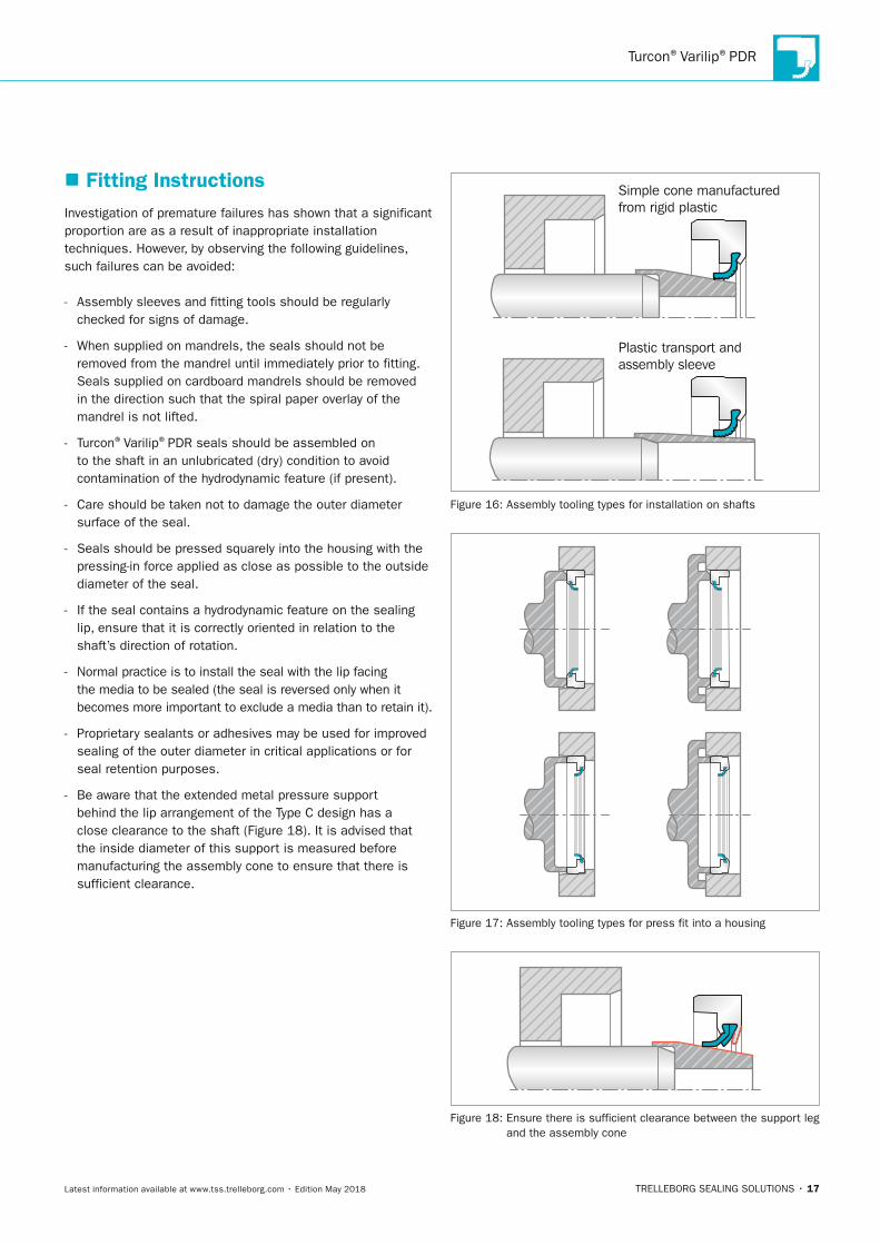
� Fitting InstructionsInvestigation of premature failures has shown that a significant proportion are as a result of inappropriate installation techniques. However, by observing the following guidelines, such failures can be avoided:
- Assembly sleeves and fitting tools should be regularly checked for signs of damage.
- When supplied on mandrels, the seals should not be removed from the mandrel until immediately prior to fitting. Seals supplied on cardboard mandrels should be removed in the direction such that the spiral paper overlay of the mandrel is not lifted.
- Turcon®Varilip®PDR seals should be assembled on to the shaft in an unlubricated (dry) condition to avoid contamination of the hydrodynamic feature (if present).
- Care should be taken not to damage the outer diameter surface of the seal.
- Seals should be pressed squarely into the housing with the pressing-in force applied as close as possible to the outside diameter of the seal.
- If the seal contains a hydrodynamic feature on the sealing lip, ensure that it is correctly oriented in relation to the shaft’s direction of rotation.
- Normal practice is to install the seal with the lip facing the media to be sealed (the seal is reversed only when it becomes more important to exclude a media than to retain it).
- Proprietary sealants or adhesives may be used for improved sealing of the outer diameter in critical applications or for seal retention purposes.
- Be aware that the extended metal pressure support behind the lip arrangement of the Type C design has a close clearance to the shaft (Figure 18). It is advised that the inside diameter of this support is measured before manufacturing the assembly cone to ensure that there is sufficient clearance.
Plastic transport andassembly sleeve
Simple cone manufacturedfrom rigid plastic
Figure 16: Assembly tooling types for installation on shafts
Figure 17: Assembly tooling types for press fit into a housing
Figure 18: Ensure there is sufficient clearance between the support leg and the assembly cone
TSS_Turcon_Varilip_PDR_2018.indd 17 14.05.2018 13:02:31

Turcon®Varilip®PDR
18 • TRELLEBORG SEALING SOLUTIONS Latest information available at www.tss.trelleborg.com • Edition May 2018
� Installation RecommendationsThe following diagrams show installation recommendations in respect to seal retention under pressurized conditions.
POST InSTAllATIOn RECOMMEnDATIOnS
If painting the housing after installation, be sure to mask the seal. Avoid getting any paint on the lip, or the shaft where the lip rides. Also, mask any vents or drain holes so they will not become clogged. Be sure to remove masks before operating unit.
If paint is to be baked, or the mechanism is otherwise subjected to heat, seals should not be heated to temperatures higher than their materials can tolerate. Contact your local Trelleborg Sealing Solutions marketing company for guidance.
When cleaning or testing, do not subject seals to any fluids or pressures other than those for which the seals have been specified.
Extraction features such as tapped holes, internal threads or simple grooves can be included in custom Turcon®Varilip®PDR designs.
20°
b1 b
1.2 mm ± 0.2 mm(0.047 in. ± 0.008 in.)
(0.02 in)R 0.5
d1 h
11
d2 H
8
Figure 19: Installation drawing for pressures up to 0.5 MPa (73 psi)
P
Figure 20: Installation for pressure from 0.5 MPa (73 psi) up to 1 MPa (145 psi). It is recommended to machine the housing to support the back of the seal.
d4
PP
min. 3.00
Figure 21: Installation type for fluid separation (Type D) at pressures up to 0.5 MPa (73 psi).
TSS_Turcon_Varilip_PDR_2018.indd 18 14.05.2018 13:02:32

Turcon®Varilip®PDR
TRELLEBORG SEALING SOLUTIONS • 19Latest information available at www.tss.trelleborg.com • Edition May 2018
� Turcon®Varilip®PDR Size Ranges
Type A / Type 1
Type B / Type 3
Type C / Type 4
Type D / Type 5
Type G / Type 6
SealMax. Shaft
SpeedMax.
Pressurem/s ft/min
60 11,811 0.5 73
40 7,874 0.5 73
20 3,937 1.0 145
40 7,874 0.5 73
60 11,811 0.5 73
This is a single lip seal suitable for use in standard industrial applica-tions where an elastomer radial shaft seal would not be able to withstand the temperature, friction, media or poor lubrication condi-tions.
The preferred choice for applications in which high seal integrity is demanded or where contaminated media are to be sealed. This type offers a back-up sealing lip to provide secondary sealing.
Note: Secondary sealing element material is Turcon® M83 in standard seal configuration.
For use in applications involving higher pressures for which a simple elastomer radial shaft seal can no longer be considered. Due to reinforcement of the sealing lip, pressures up to 1 MPa (145 psi) are possible, e.g. as pump, shaft or rotor seals.
Note: Secondary support element material is M83 (not modifiable). Turcon® M83 is the recommended primary lip material.
For use in applications where the seal is subjected to pressure from both sides and/or applications where the seperation of two different media using a single seal is required.
Note: Secondary sealing element material is Turcon® M83 in standard seal configuration.
Similar configuration to Type D / Type 5 but has a non-contacting environmental sealing element rather than a full lay-down lip. This provides effective sealing against the ingress of external contami-nants into the system whilst also ensuring torque and resulting power consumption are kept to a minimum.
Note: Secondary dust/dirt element material is Turcon® T01 in standard seal configuration (not modifiable).
DescriptionMPa psi
Type A/Type 1
Type A / Type 1
Type B / Type 3
Type C / Type 4
Type D / Type 5
Type G / Type 6
SealMax. Shaft
SpeedMax.
Pressurem/s ft/min
60 11,811 0.5 73
40 7,874 0.5 73
20 3,937 1.0 145
40 7,874 0.5 73
60 11,811 0.5 73
This is a single lip seal suitable for use in standard industrial applica-tions where an elastomer radial shaft seal would not be able to withstand the temperature, friction, media or poor lubrication condi-tions.
The preferred choice for applications in which high seal integrity is demanded or where contaminated media are to be sealed. This type offers a back-up sealing lip to provide secondary sealing.
Note: Secondary sealing element material is Turcon® M83 in standard seal configuration.
For use in applications involving higher pressures for which a simple elastomer radial shaft seal can no longer be considered. Due to reinforcement of the sealing lip, pressures up to 1 MPa (145 psi) are possible, e.g. as pump, shaft or rotor seals.
Note: Secondary support element material is M83 (not modifiable). Turcon® M83 is the recommended primary lip material.
For use in applications where the seal is subjected to pressure from both sides and/or applications where the seperation of two different media using a single seal is required.
Note: Secondary sealing element material is Turcon® M83 in standard seal configuration.
Similar configuration to Type D / Type 5 but has a non-contacting environmental sealing element rather than a full lay-down lip. This provides effective sealing against the ingress of external contami-nants into the system whilst also ensuring torque and resulting power consumption are kept to a minimum.
Note: Secondary dust/dirt element material is Turcon® T01 in standard seal configuration (not modifiable).
DescriptionMPa psi
Type B/Type 3
Type A / Type 1
Type B / Type 3
Type C / Type 4
Type D / Type 5
Type G / Type 6
SealMax. Shaft
SpeedMax.
Pressurem/s ft/min
60 11,811 0.5 73
40 7,874 0.5 73
20 3,937 1.0 145
40 7,874 0.5 73
60 11,811 0.5 73
This is a single lip seal suitable for use in standard industrial applica-tions where an elastomer radial shaft seal would not be able to withstand the temperature, friction, media or poor lubrication condi-tions.
The preferred choice for applications in which high seal integrity is demanded or where contaminated media are to be sealed. This type offers a back-up sealing lip to provide secondary sealing.
Note: Secondary sealing element material is Turcon® M83 in standard seal configuration.
For use in applications involving higher pressures for which a simple elastomer radial shaft seal can no longer be considered. Due to reinforcement of the sealing lip, pressures up to 1 MPa (145 psi) are possible, e.g. as pump, shaft or rotor seals.
Note: Secondary support element material is M83 (not modifiable). Turcon® M83 is the recommended primary lip material.
For use in applications where the seal is subjected to pressure from both sides and/or applications where the seperation of two different media using a single seal is required.
Note: Secondary sealing element material is Turcon® M83 in standard seal configuration.
Similar configuration to Type D / Type 5 but has a non-contacting environmental sealing element rather than a full lay-down lip. This provides effective sealing against the ingress of external contami-nants into the system whilst also ensuring torque and resulting power consumption are kept to a minimum.
Note: Secondary dust/dirt element material is Turcon® T01 in standard seal configuration (not modifiable).
DescriptionMPa psi
Type C/Type 4
Type A / Type 1
Type B / Type 3
Type C / Type 4
Type D / Type 5
Type G / Type 6
SealMax. Shaft
SpeedMax.
Pressurem/s ft/min
60 11,811 0.5 73
40 7,874 0.5 73
20 3,937 1.0 145
40 7,874 0.5 73
60 11,811 0.5 73
This is a single lip seal suitable for use in standard industrial applica-tions where an elastomer radial shaft seal would not be able to withstand the temperature, friction, media or poor lubrication condi-tions.
The preferred choice for applications in which high seal integrity is demanded or where contaminated media are to be sealed. This type offers a back-up sealing lip to provide secondary sealing.
Note: Secondary sealing element material is Turcon® M83 in standard seal configuration.
For use in applications involving higher pressures for which a simple elastomer radial shaft seal can no longer be considered. Due to reinforcement of the sealing lip, pressures up to 1 MPa (145 psi) are possible, e.g. as pump, shaft or rotor seals.
Note: Secondary support element material is M83 (not modifiable). Turcon® M83 is the recommended primary lip material.
For use in applications where the seal is subjected to pressure from both sides and/or applications where the seperation of two different media using a single seal is required.
Note: Secondary sealing element material is Turcon® M83 in standard seal configuration.
Similar configuration to Type D / Type 5 but has a non-contacting environmental sealing element rather than a full lay-down lip. This provides effective sealing against the ingress of external contami-nants into the system whilst also ensuring torque and resulting power consumption are kept to a minimum.
Note: Secondary dust/dirt element material is Turcon® T01 in standard seal configuration (not modifiable).
DescriptionMPa psi
Type D/Type 5
Type A / Type 1
Type B / Type 3
Type C / Type 4
Type D / Type 5
Type G / Type 6
SealMax. Shaft
SpeedMax.
Pressurem/s ft/min
60 11,811 0.5 73
40 7,874 0.5 73
20 3,937 1.0 145
40 7,874 0.5 73
60 11,811 0.5 73
This is a single lip seal suitable for use in standard industrial applica-tions where an elastomer radial shaft seal would not be able to withstand the temperature, friction, media or poor lubrication condi-tions.
The preferred choice for applications in which high seal integrity is demanded or where contaminated media are to be sealed. This type offers a back-up sealing lip to provide secondary sealing.
Note: Secondary sealing element material is Turcon® M83 in standard seal configuration.
For use in applications involving higher pressures for which a simple elastomer radial shaft seal can no longer be considered. Due to reinforcement of the sealing lip, pressures up to 1 MPa (145 psi) are possible, e.g. as pump, shaft or rotor seals.
Note: Secondary support element material is M83 (not modifiable). Turcon® M83 is the recommended primary lip material.
For use in applications where the seal is subjected to pressure from both sides and/or applications where the seperation of two different media using a single seal is required.
Note: Secondary sealing element material is Turcon® M83 in standard seal configuration.
Similar configuration to Type D / Type 5 but has a non-contacting environmental sealing element rather than a full lay-down lip. This provides effective sealing against the ingress of external contami-nants into the system whilst also ensuring torque and resulting power consumption are kept to a minimum.
Note: Secondary dust/dirt element material is Turcon® T01 in standard seal configuration (not modifiable).
DescriptionMPa psi
Type G/Type 6
Table 12: Turcon®Varilip®PDR Metric Size Range
Shaft Diameter
Bore Diameter
Seal length (b)
Bore Depth (b1)
Retention Diameter
TSS Part no.
d1 (mm)
d2 (mm)
exc. TJB(mm)
TJB(mm)
exc. TJB (mm)
TJB (mm)
d4 min. (TJD) (mm)
6.0 16.0 7.0 10.0 7.3 10.3 9.6 TJ_1_0060
6.0 22.0 7.0 10.0 7.3 10.3 9.6 TJ_2_0060
7.0 22.0 7.0 10.0 7.3 10.3 10.6 TJ_1_0070
8.0 22.0 7.0 10.0 7.3 10.3 11.6 TJ_1_0080
8.0 24.0 7.0 10.0 7.3 10.3 11.6 TJ_2_0080
9.0 22.0 7.0 10.0 7.3 10.3 12.6 TJ_1_0090
9.0 24.0 7.0 10.0 7.3 10.3 12.6 TJ_2_0090
9.0 26.0 7.0 10.0 7.3 10.3 12.6 TJ_3_0090
10.0 22.0 7.0 10.0 7.3 10.3 13.6 TJ_1_0100
10.0 24.0 7.0 10.0 7.3 10.3 13.6 TJ_2_0100
10.0 25.0 7.0 10.0 7.3 10.3 13.6 TJ_3_0100
10.0 26.0 7.0 10.0 7.3 10.3 13.6 TJ_4_0100
11.0 22.0 7.0 10.0 7.3 10.3 14.6 TJ_1_0110
11.0 26.0 7.0 10.0 7.3 10.3 14.6 TJ_2_0110
12.0 22.0 7.0 10.0 7.3 10.3 15.6 TJ_1_0120
12.0 24.0 7.0 10.0 7.3 10.3 15.6 TJ_2_0120
12.0 25.0 7.0 10.0 7.3 10.3 15.6 TJ_3_0120
12.0 28.0 7.0 10.0 7.3 10.3 15.6 TJ_4_0120
12.0 30.0 7.0 10.0 7.3 10.3 15.6 TJ_5_0120
14.0 24.0 7.0 10.0 7.3 10.3 17.6 TJ_1_0140
14.0 28.0 7.0 10.0 7.3 10.3 17.6 TJ_2_0140
14.0 30.0 7.0 10.0 7.3 10.3 17.6 TJ_3_0140
14.0 35.0 7.0 10.0 7.3 10.3 17.6 TJ_4_0140
15.0 26.0 7.0 10.0 7.3 10.3 18.6 TJ_1_0150
15.0 30.0 7.0 10.0 7.3 10.3 18.6 TJ_2_0150
15.0 32.0 7.0 10.0 7.3 10.3 18.6 TJ_3_0150
15.0 35.0 7.0 10.0 7.3 10.3 18.6 TJ_4_0150
According to ISO 6194/1 and ISO 16589. Sealing lips may, in some cases, protrude beyond the edge of the seal body. Sizes not stated on these tables are available on request. (Note that this will include a tooling charge).
TSS_Turcon_Varilip_PDR_2018.indd 19 14.05.2018 13:02:32

Turcon®Varilip®PDR
20 • TRELLEBORG SEALING SOLUTIONS Latest information available at www.tss.trelleborg.com • Edition May 2018
Shaft Diameter
Bore Diameter
Seal length (b)
Bore Depth (b1)
Retention Diameter
TSS Part no.
d1 (mm)
d2 (mm)
exc. TJB(mm)
TJB(mm)
exc. TJB (mm)
TJB (mm)
d4 min. (TJD) (mm)
16.0 28.0 7.0 10.0 7.3 10.3 19.6 TJ_1_0160
16.0 30.0 7.0 10.0 7.3 10.3 19.6 TJ_2_0160
16.0 32.0 7.0 10.0 7.3 10.3 19.6 TJ_3_0160
16.0 35.0 7.0 10.0 7.3 10.3 19.6 TJ_4_0160
17.0 28.0 7.0 10.0 7.3 10.3 20.6 TJ_1_0170
17.0 30.0 7.0 10.0 7.3 10.3 20.6 TJ_2_0170
17.0 32.0 7.0 10.0 7.3 10.3 20.6 TJ_3_0170
17.0 35.0 7.0 10.0 7.3 10.3 20.6 TJ_4_0170
17.0 40.0 7.0 10.0 7.3 10.3 20.6 TJ_5_0170
18.0 30.0 7.0 10.0 7.3 10.3 21.6 TJ_1_0180
18.0 32.0 7.0 10.0 7.3 10.3 21.6 TJ_2_0180
18.0 35.0 7.0 10.0 7.3 10.3 21.6 TJ_3_0180
18.0 40.0 7.0 10.0 7.3 10.3 21.6 TJ_4_0180
20.0 30.0 7.0 10.0 7.3 10.3 23.6 TJ_1_0200
20.0 32.0 7.0 10.0 7.3 10.3 23.6 TJ_2_0200
20.0 35.0 7.0 10.0 7.3 10.3 23.6 TJ_3_0200
20.0 40.0 7.0 10.0 7.3 10.3 23.6 TJ_4_0200
20.0 47.0 7.0 10.0 7.3 10.3 23.6 TJ_5_0200
22.0 32.0 7.0 10.0 7.3 10.3 25.6 TJ_1_0220
22.0 35.0 7.0 10.0 7.3 10.3 25.6 TJ_2_0220
22.0 40.0 7.0 10.0 7.3 10.3 25.6 TJ_3_0220
22.0 47.0 7.0 10.0 7.3 10.3 25.6 TJ_4_0220
24.0 35.0 7.0 10.0 7.3 10.3 27.6 TJ_1_0240
24.0 37.0 7.0 10.0 7.3 10.3 27.6 TJ_2_0240
24.0 40.0 7.0 10.0 7.3 10.3 27.6 TJ_3_0240
24.0 47.0 7.0 10.0 7.3 10.3 27.6 TJ_4_0240
26.0 37.0 7.0 10.0 7.3 10.3 29.6 TJ_1_0260
26.0 42.0 7.0 10.0 7.3 10.3 29.6 TJ_2_0260
26.0 47.0 7.0 10.0 7.3 10.3 29.6 TJ_3_0260
28.0 40.0 7.0 10.0 7.3 10.3 31.6 TJ_1_0280
28.0 47.0 7.0 10.0 7.3 10.3 31.6 TJ_2_0280
28.0 52.0 7.0 10.0 7.3 10.3 31.6 TJ_3_0280
30.0 40.0 7.0 10.0 7.3 10.3 33.6 TJ_1_0300
30.0 42.0 7.0 10.0 7.3 10.3 33.6 TJ_2_0300
30.0 47.0 7.0 10.0 7.3 10.3 33.6 TJ_3_0300
30.0 52.0 7.0 10.0 7.3 10.3 33.6 TJ_4_0300
30.0 62.0 7.0 10.0 7.3 10.3 33.6 TJ_5_0300
32.0 45.0 7.0 10.0 7.3 10.3 35.6 TJ_1_0320
32.0 45.0 8.0 10.0 8.3 10.3 35.6 TJ_2_0320
According to ISO 6194/1 and ISO 16589. Sealing lips may, in some cases, protrude beyond the edge of the seal body. Sizes not stated on these tables are available on request. (Note that this will include a tooling charge).
TSS_Turcon_Varilip_PDR_2018.indd 20 14.05.2018 13:02:32

Turcon®Varilip®PDR
TRELLEBORG SEALING SOLUTIONS • 21Latest information available at www.tss.trelleborg.com • Edition May 2018
Shaft Diameter
Bore Diameter
Seal length (b)
Bore Depth (b1)
Retention Diameter
TSS Part no.
d1 (mm)
d2 (mm)
exc. TJB(mm)
TJB(mm)
exc. TJB (mm)
TJB (mm)
d4 min. (TJD) (mm)
32.0 47.0 7.0 10.0 7.3 10.3 35.6 TJ_3_0320
32.0 47.0 8.0 10.0 8.3 10.3 35.6 TJ_4_0320
32.0 52.0 7.0 10.0 7.3 10.3 35.6 TJ_5_0320
32.0 52.0 8.0 10.0 8.3 10.3 35.6 TJ_6_0320
35.0 47.0 7.0 10.0 7.3 10.3 38.6 TJ_1_0350
35.0 50.0 7.0 10.0 7.3 10.3 38.6 TJ_2_0350
35.0 50.0 8.0 10.0 8.3 10.3 38.6 TJ_3_0350
35.0 52.0 7.0 10.0 7.3 10.3 38.6 TJ_4_0350
35.0 52.0 8.0 10.0 8.3 10.3 38.6 TJ_5_0350
35.0 55.0 8.0 10.0 8.3 10.3 38.6 TJ_6_0350
35.0 62.0 7.0 10.0 7.3 10.3 38.6 TJ_7_0350
36.0 47.0 7.0 10.0 7.3 10.3 39.6 TJ_1_0360
36.0 50.0 7.0 10.0 7.3 10.3 39.6 TJ_2_0360
36.0 52.0 7.0 10.0 7.3 10.3 39.6 TJ_3_0360
36.0 62.0 7.0 10.0 7.3 10.3 39.6 TJ_4_0360
38.0 52.0 7.0 10.0 7.3 10.3 41.6 TJ_1_0380
38.0 55.0 7.0 10.0 7.3 10.3 41.6 TJ_2_0380
38.0 55.0 8.0 10.0 8.3 10.3 41.6 TJ_3_0380
38.0 58.0 8.0 10.0 8.3 10.3 41.6 TJ_4_0380
38.0 62.0 7.0 10.0 7.3 10.3 41.6 TJ_5_0380
38.0 62.0 8.0 10.0 8.3 10.3 41.6 TJ_6_0380
40.0 52.0 7.0 10.0 7.3 10.3 43.6 TJ_1_0400
40.0 55.0 7.0 10.0 7.3 10.3 43.6 TJ_2_0400
40.0 55.0 8.0 10.0 8.3 10.3 43.6 TJ_3_0400
40.0 62.0 7.0 10.0 7.3 10.3 43.6 TJ_4_0400
40.0 62.0 8.0 10.0 8.3 10.3 43.6 TJ_5_0400
40.0 72.0 7.0 10.0 7.3 10.3 43.6 TJ_6_0400
42.0 55.0 8.0 10.0 8.3 10.3 45.6 TJ_1_0420
42.0 62.0 8.0 10.0 8.3 10.3 45.6 TJ_2_0420
42.0 72.0 8.0 10.0 8.3 10.3 45.6 TJ_3_0420
45.0 60.0 8.0 10.0 8.3 10.3 48.6 TJ_1_0450
45.0 62.0 8.0 10.0 8.3 10.3 48.6 TJ_2_0450
45.0 65.0 8.0 10.0 8.3 10.3 48.6 TJ_3_0450
45.0 72.0 8.0 10.0 8.3 10.3 48.6 TJ_4_0450
48.0 62.0 8.0 10.0 8.3 10.3 51.6 TJ_1_0480
48.0 72.0 8.0 10.0 8.3 10.3 51.6 TJ_2_0480
50.0 65.0 8.0 10.0 8.3 10.3 53.6 TJ_1_0500
50.0 68.0 8.0 10.0 8.3 10.3 53.6 TJ_2_0500
50.0 72.0 8.0 10.0 8.3 10.3 53.6 TJ_3_0500
According to ISO 6194/1 and ISO 16589. Sealing lips may, in some cases, protrude beyond the edge of the seal body. Sizes not stated on these tables are available on request. (Note that this will include a tooling charge).
TSS_Turcon_Varilip_PDR_2018.indd 21 14.05.2018 13:02:33

Turcon®Varilip®PDR
22 • TRELLEBORG SEALING SOLUTIONS Latest information available at www.tss.trelleborg.com • Edition May 2018
Shaft Diameter
Bore Diameter
Seal length (b)
Bore Depth (b1)
Retention Diameter
TSS Part no.
d1 (mm)
d2 (mm)
exc. TJB(mm)
TJB(mm)
exc. TJB (mm)
TJB (mm)
d4 min. (TJD) (mm)
50.0 80.0 8.0 10.0 8.3 10.3 53.6 TJ_4_0500
52.0 68.0 8.0 10.0 8.3 10.3 55.6 TJ_1_0520
52.0 72.0 8.0 10.0 8.3 10.3 55.6 TJ_2_0520
55.0 70.0 8.0 10.0 8.3 10.3 58.6 TJ_1_0550
55.0 72.0 8.0 10.0 8.3 10.3 58.6 TJ_2_0550
55.0 80.0 8.0 10.0 8.3 10.3 58.6 TJ_3_0550
55.0 85.0 8.0 10.0 8.3 10.3 58.6 TJ_4_0550
56.0 70.0 8.0 10.0 8.3 10.3 59.6 TJ_1_0560
56.0 72.0 8.0 10.0 8.3 10.3 59.6 TJ_2_0560
56.0 80.0 8.0 10.0 8.3 10.3 59.6 TJ_3_0560
56.0 85.0 8.0 10.0 8.3 10.3 59.6 TJ_4_0560
58.0 72.0 8.0 10.0 8.3 10.3 61.6 TJ_1_0580
58.0 80.0 8.0 10.0 8.3 10.3 61.6 TJ_2_0580
60.0 75.0 8.0 10.0 8.3 10.3 63.6 TJ_1_0600
60.0 80.0 8.0 10.0 8.3 10.3 63.6 TJ_2_0600
60.0 85.0 8.0 10.0 8.3 10.3 63.6 TJ_3_0600
60.0 90.0 8.0 10.0 8.3 10.3 63.6 TJ_4_0600
62.0 85.0 10.0 10.0 10.3 10.3 66.4 TJ_1_0620
62.0 90.0 10.0 10.0 10.3 10.3 66.4 TJ_2_0620
63.0 85.0 10.0 10.0 10.3 10.3 67.4 TJ_1_0630
63.0 90.0 10.0 10.0 10.3 10.3 67.4 TJ_2_0630
65.0 85.0 10.0 10.0 10.3 10.3 69.4 TJ_1_0650
65.0 90.0 10.0 10.0 10.3 10.3 69.4 TJ_2_0650
65.0 100.0 10.0 10.0 10.3 10.3 69.4 TJ_3_0650
68.0 90.0 10.0 10.0 10.3 10.3 72.4 TJ_1_0680
68.0 100.0 10.0 10.0 10.3 10.3 72.4 TJ_2_0680
70.0 90.0 10.0 10.0 10.3 10.3 74.4 TJ_1_0700
70.0 95.0 10.0 10.0 10.3 10.3 74.4 TJ_2_0700
70.0 100.0 10.0 10.0 10.3 10.3 74.4 TJ_3_0700
72.0 95.0 10.0 10.0 10.3 10.3 76.4 TJ_1_0720
72.0 100.0 10.0 10.0 10.3 10.3 76.4 TJ_2_0720
75.0 95.0 10.0 10.0 10.3 10.3 79.4 TJ_1_0750
75.0 100.0 10.0 10.0 10.3 10.3 79.4 TJ_2_0750
78.0 100.0 10.0 10.0 10.3 10.3 82.4 TJ_1_0780
80.0 100.0 10.0 10.0 10.3 10.3 84.4 TJ_1_0800
80.0 110.0 10.0 10.0 10.3 10.3 84.4 TJ_2_0800
85.0 110.0 12.0 12.0 12.3 12.3 89.4 TJ_1_0850
85.0 120.0 12.0 12.0 12.3 12.3 89.4 TJ_2_0850
90.0 110.0 12.0 12.0 12.3 12.3 94.4 TJ_1_0900
According to ISO 6194/1 and ISO 16589. Sealing lips may, in some cases, protrude beyond the edge of the seal body. Sizes not stated on these tables are available on request. (Note that this will include a tooling charge).
TSS_Turcon_Varilip_PDR_2018.indd 22 14.05.2018 13:02:33
Turcon®Varilip®PDR
TRELLEBORG SEALING SOLUTIONS • 23Latest information available at www.tss.trelleborg.com • Edition May 2018
Shaft Diameter
Bore Diameter
Seal length (b)
Bore Depth (b1)
Retention Diameter
TSS Part no.
d1 (mm)
d2 (mm)
exc. TJB(mm)
TJB(mm)
exc. TJB (mm)
TJB (mm)
d4 min. (TJD) (mm)
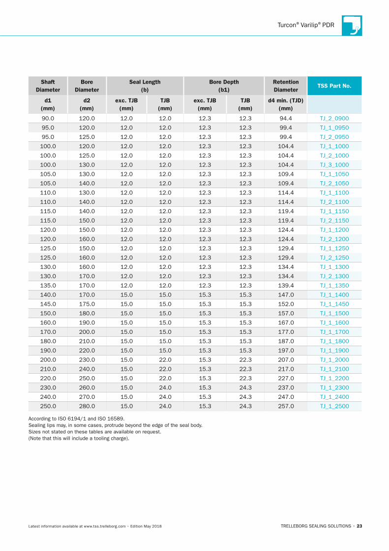
90.0 120.0 12.0 12.0 12.3 12.3 94.4 TJ_2_0900
95.0 120.0 12.0 12.0 12.3 12.3 99.4 TJ_1_0950
95.0 125.0 12.0 12.0 12.3 12.3 99.4 TJ_2_0950
100.0 120.0 12.0 12.0 12.3 12.3 104.4 TJ_1_1000
100.0 125.0 12.0 12.0 12.3 12.3 104.4 TJ_2_1000
100.0 130.0 12.0 12.0 12.3 12.3 104.4 TJ_3_1000
105.0 130.0 12.0 12.0 12.3 12.3 109.4 TJ_1_1050
105.0 140.0 12.0 12.0 12.3 12.3 109.4 TJ_2_1050
110.0 130.0 12.0 12.0 12.3 12.3 114.4 TJ_1_1100
110.0 140.0 12.0 12.0 12.3 12.3 114.4 TJ_2_1100
115.0 140.0 12.0 12.0 12.3 12.3 119.4 TJ_1_1150
115.0 150.0 12.0 12.0 12.3 12.3 119.4 TJ_2_1150
120.0 150.0 12.0 12.0 12.3 12.3 124.4 TJ_1_1200
120.0 160.0 12.0 12.0 12.3 12.3 124.4 TJ_2_1200
125.0 150.0 12.0 12.0 12.3 12.3 129.4 TJ_1_1250
125.0 160.0 12.0 12.0 12.3 12.3 129.4 TJ_2_1250
130.0 160.0 12.0 12.0 12.3 12.3 134.4 TJ_1_1300
130.0 170.0 12.0 12.0 12.3 12.3 134.4 TJ_2_1300
135.0 170.0 12.0 12.0 12.3 12.3 139.4 TJ_1_1350
140.0 170.0 15.0 15.0 15.3 15.3 147.0 TJ_1_1400
145.0 175.0 15.0 15.0 15.3 15.3 152.0 TJ_1_1450
150.0 180.0 15.0 15.0 15.3 15.3 157.0 TJ_1_1500
160.0 190.0 15.0 15.0 15.3 15.3 167.0 TJ_1_1600
170.0 200.0 15.0 15.0 15.3 15.3 177.0 TJ_1_1700
180.0 210.0 15.0 15.0 15.3 15.3 187.0 TJ_1_1800
190.0 220.0 15.0 15.0 15.3 15.3 197.0 TJ_1_1900
200.0 230.0 15.0 22.0 15.3 22.3 207.0 TJ_1_2000
210.0 240.0 15.0 22.0 15.3 22.3 217.0 TJ_1_2100
220.0 250.0 15.0 22.0 15.3 22.3 227.0 TJ_1_2200
230.0 260.0 15.0 24.0 15.3 24.3 237.0 TJ_1_2300
240.0 270.0 15.0 24.0 15.3 24.3 247.0 TJ_1_2400
250.0 280.0 15.0 24.0 15.3 24.3 257.0 TJ_1_2500
According to ISO 6194/1 and ISO 16589. Sealing lips may, in some cases, protrude beyond the edge of the seal body. Sizes not stated on these tables are available on request. (Note that this will include a tooling charge).
TSS_Turcon_Varilip_PDR_2018.indd 23 14.05.2018 13:02:33
Turcon®Varilip®PDR
24 • TRELLEBORG SEALING SOLUTIONS Latest information available at www.tss.trelleborg.com • Edition May 2018
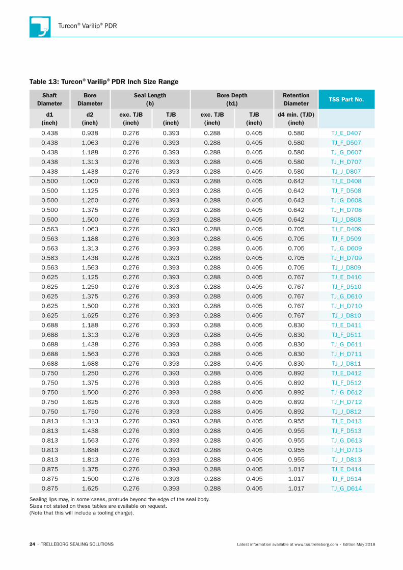
Table 13: Turcon®Varilip®PDR Inch Size Range
Shaft Diameter
Bore Diameter
Seal length (b)
Bore Depth (b1)
Retention Diameter
TSS Part no.
d1 (inch)
d2 (inch)
exc. TJB(inch)
TJB(inch)
exc. TJB (inch)
TJB (inch)
d4 min. (TJD) (inch)
0.438 0.938 0.276 0.393 0.288 0.405 0.580 TJ_E_D407
0.438 1.063 0.276 0.393 0.288 0.405 0.580 TJ_F_D507
0.438 1.188 0.276 0.393 0.288 0.405 0.580 TJ_G_D607
0.438 1.313 0.276 0.393 0.288 0.405 0.580 TJ_H_D707
0.438 1.438 0.276 0.393 0.288 0.405 0.580 TJ_J_D807
0.500 1.000 0.276 0.393 0.288 0.405 0.642 TJ_E_D408
0.500 1.125 0.276 0.393 0.288 0.405 0.642 TJ_F_D508
0.500 1.250 0.276 0.393 0.288 0.405 0.642 TJ_G_D608
0.500 1.375 0.276 0.393 0.288 0.405 0.642 TJ_H_D708
0.500 1.500 0.276 0.393 0.288 0.405 0.642 TJ_J_D808
0.563 1.063 0.276 0.393 0.288 0.405 0.705 TJ_E_D409
0.563 1.188 0.276 0.393 0.288 0.405 0.705 TJ_F_D509
0.563 1.313 0.276 0.393 0.288 0.405 0.705 TJ_G_D609
0.563 1.438 0.276 0.393 0.288 0.405 0.705 TJ_H_D709
0.563 1.563 0.276 0.393 0.288 0.405 0.705 TJ_J_D809
0.625 1.125 0.276 0.393 0.288 0.405 0.767 TJ_E_D410
0.625 1.250 0.276 0.393 0.288 0.405 0.767 TJ_F_D510
0.625 1.375 0.276 0.393 0.288 0.405 0.767 TJ_G_D610
0.625 1.500 0.276 0.393 0.288 0.405 0.767 TJ_H_D710
0.625 1.625 0.276 0.393 0.288 0.405 0.767 TJ_J_D810
0.688 1.188 0.276 0.393 0.288 0.405 0.830 TJ_E_D411
0.688 1.313 0.276 0.393 0.288 0.405 0.830 TJ_F_D511
0.688 1.438 0.276 0.393 0.288 0.405 0.830 TJ_G_D611
0.688 1.563 0.276 0.393 0.288 0.405 0.830 TJ_H_D711
0.688 1.688 0.276 0.393 0.288 0.405 0.830 TJ_J_D811
0.750 1.250 0.276 0.393 0.288 0.405 0.892 TJ_E_D412
0.750 1.375 0.276 0.393 0.288 0.405 0.892 TJ_F_D512
0.750 1.500 0.276 0.393 0.288 0.405 0.892 TJ_G_D612
0.750 1.625 0.276 0.393 0.288 0.405 0.892 TJ_H_D712
0.750 1.750 0.276 0.393 0.288 0.405 0.892 TJ_J_D812
0.813 1.313 0.276 0.393 0.288 0.405 0.955 TJ_E_D413
0.813 1.438 0.276 0.393 0.288 0.405 0.955 TJ_F_D513
0.813 1.563 0.276 0.393 0.288 0.405 0.955 TJ_G_D613
0.813 1.688 0.276 0.393 0.288 0.405 0.955 TJ_H_D713
0.813 1.813 0.276 0.393 0.288 0.405 0.955 TJ_J_D813
0.875 1.375 0.276 0.393 0.288 0.405 1.017 TJ_E_D414
0.875 1.500 0.276 0.393 0.288 0.405 1.017 TJ_F_D514
0.875 1.625 0.276 0.393 0.288 0.405 1.017 TJ_G_D614
Sealing lips may, in some cases, protrude beyond the edge of the seal body. Sizes not stated on these tables are available on request. (Note that this will include a tooling charge).
TSS_Turcon_Varilip_PDR_2018.indd 24 14.05.2018 13:02:33
Turcon®Varilip®PDR
TRELLEBORG SEALING SOLUTIONS • 25Latest information available at www.tss.trelleborg.com • Edition May 2018
Shaft Diameter
Bore Diameter
Seal length (b)
Bore Depth (b1)
Retention Diameter
TSS Part no.
d1 (inch)
d2 (inch)
exc. TJB(inch)
TJB(inch)
exc. TJB (inch)
TJB (inch)
d4 min. (TJD) (inch)
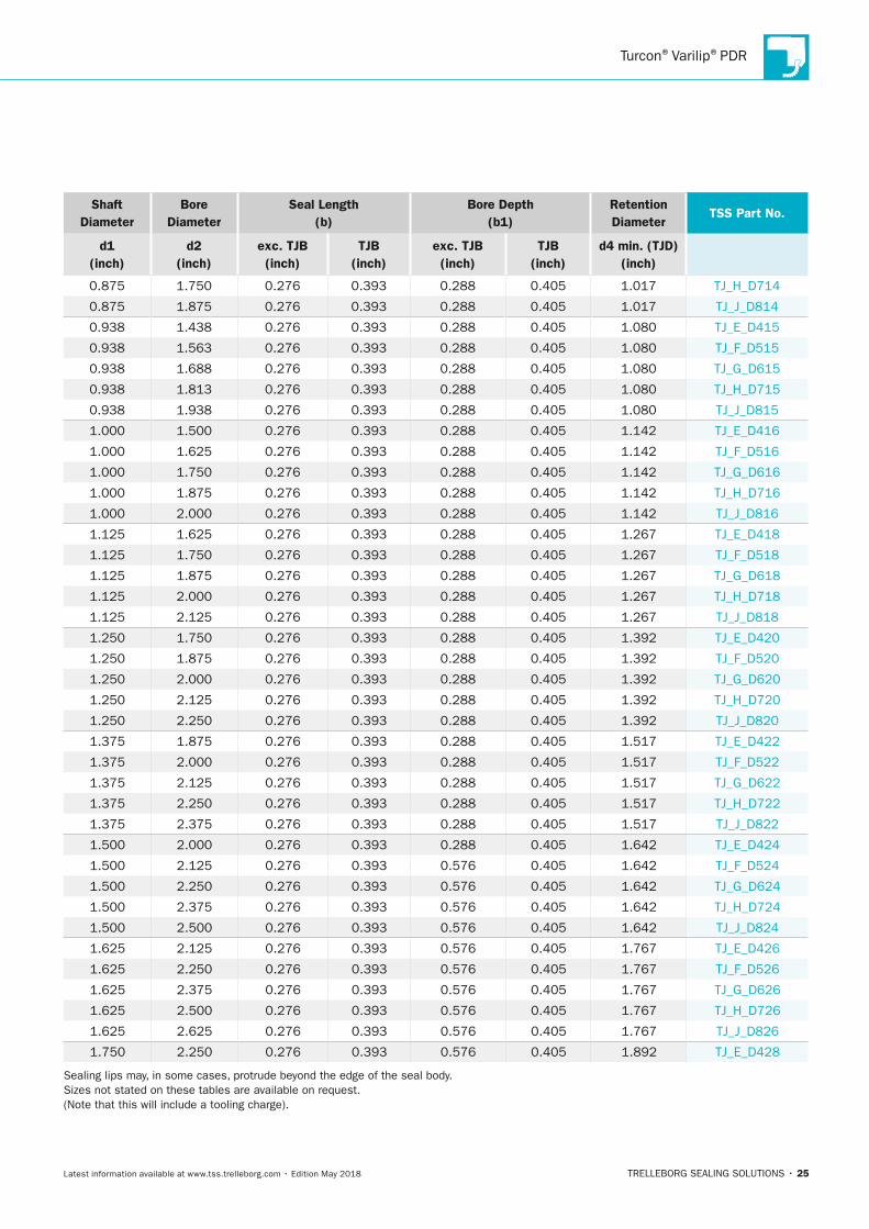
0.875 1.750 0.276 0.393 0.288 0.405 1.017 TJ_H_D714
0.875 1.875 0.276 0.393 0.288 0.405 1.017 TJ_J_D814
0.938 1.438 0.276 0.393 0.288 0.405 1.080 TJ_E_D415
0.938 1.563 0.276 0.393 0.288 0.405 1.080 TJ_F_D515
0.938 1.688 0.276 0.393 0.288 0.405 1.080 TJ_G_D615
0.938 1.813 0.276 0.393 0.288 0.405 1.080 TJ_H_D715
0.938 1.938 0.276 0.393 0.288 0.405 1.080 TJ_J_D815
1.000 1.500 0.276 0.393 0.288 0.405 1.142 TJ_E_D416
1.000 1.625 0.276 0.393 0.288 0.405 1.142 TJ_F_D516
1.000 1.750 0.276 0.393 0.288 0.405 1.142 TJ_G_D616
1.000 1.875 0.276 0.393 0.288 0.405 1.142 TJ_H_D716
1.000 2.000 0.276 0.393 0.288 0.405 1.142 TJ_J_D816
1.125 1.625 0.276 0.393 0.288 0.405 1.267 TJ_E_D418
1.125 1.750 0.276 0.393 0.288 0.405 1.267 TJ_F_D518
1.125 1.875 0.276 0.393 0.288 0.405 1.267 TJ_G_D618
1.125 2.000 0.276 0.393 0.288 0.405 1.267 TJ_H_D718
1.125 2.125 0.276 0.393 0.288 0.405 1.267 TJ_J_D818
1.250 1.750 0.276 0.393 0.288 0.405 1.392 TJ_E_D420
1.250 1.875 0.276 0.393 0.288 0.405 1.392 TJ_F_D520
1.250 2.000 0.276 0.393 0.288 0.405 1.392 TJ_G_D620
1.250 2.125 0.276 0.393 0.288 0.405 1.392 TJ_H_D720
1.250 2.250 0.276 0.393 0.288 0.405 1.392 TJ_J_D820
1.375 1.875 0.276 0.393 0.288 0.405 1.517 TJ_E_D422
1.375 2.000 0.276 0.393 0.288 0.405 1.517 TJ_F_D522
1.375 2.125 0.276 0.393 0.288 0.405 1.517 TJ_G_D622
1.375 2.250 0.276 0.393 0.288 0.405 1.517 TJ_H_D722
1.375 2.375 0.276 0.393 0.288 0.405 1.517 TJ_J_D822
1.500 2.000 0.276 0.393 0.288 0.405 1.642 TJ_E_D424
1.500 2.125 0.276 0.393 0.576 0.405 1.642 TJ_F_D524
1.500 2.250 0.276 0.393 0.576 0.405 1.642 TJ_G_D624
1.500 2.375 0.276 0.393 0.576 0.405 1.642 TJ_H_D724
1.500 2.500 0.276 0.393 0.576 0.405 1.642 TJ_J_D824
1.625 2.125 0.276 0.393 0.576 0.405 1.767 TJ_E_D426
1.625 2.250 0.276 0.393 0.576 0.405 1.767 TJ_F_D526
1.625 2.375 0.276 0.393 0.576 0.405 1.767 TJ_G_D626
1.625 2.500 0.276 0.393 0.576 0.405 1.767 TJ_H_D726
1.625 2.625 0.276 0.393 0.576 0.405 1.767 TJ_J_D826
1.750 2.250 0.276 0.393 0.576 0.405 1.892 TJ_E_D428
Sealing lips may, in some cases, protrude beyond the edge of the seal body. Sizes not stated on these tables are available on request. (Note that this will include a tooling charge).
TSS_Turcon_Varilip_PDR_2018.indd 25 14.05.2018 13:02:34

Turcon®Varilip®PDR
26 • TRELLEBORG SEALING SOLUTIONS Latest information available at www.tss.trelleborg.com • Edition May 2018
Shaft Diameter
Bore Diameter
Seal length (b)
Bore Depth (b1)
Retention Diameter
TSS Part no.
d1 (inch)
d2 (inch)
exc. TJB(inch)
TJB(inch)
exc. TJB (inch)
TJB (inch)
d4 min. (TJD) (inch)
1.750 2.375 0.276 0.393 0.576 0.405 1.892 TJ_F_D528
1.750 2.500 0.276 0.393 0.576 0.405 1.892 TJ_G_D628
1.750 2.625 0.276 0.393 0.576 0.405 1.892 TJ_H_D728
1.750 2.750 0.276 0.393 0.576 0.405 1.892 TJ_J_D828
1.875 2.375 0.276 0.393 0.576 0.405 2.017 TJ_E_D430
1.875 2.500 0.276 0.393 0.576 0.405 2.017 TJ_F_D530
1.875 2.625 0.276 0.393 0.576 0.405 2.017 TJ_G_D630
1.875 2.750 0.276 0.393 0.576 0.405 2.017 TJ_H_D730
1.875 2.875 0.276 0.393 0.576 0.405 2.017 TJ_J_D830
2.000 2.500 0.276 0.393 0.576 0.405 2.142 TJ_E_D432
2.000 2.625 0.276 0.393 0.576 0.405 2.142 TJ_F_D532
2.000 2.750 0.276 0.393 0.576 0.405 2.142 TJ_G_D632
2.000 2.875 0.276 0.393 0.576 0.405 2.142 TJ_H_D732
2.000 3.000 0.276 0.393 0.576 0.405 2.142 TJ_J_D832
2.125 2.625 0.276 0.393 0.576 0.405 2.267 TJ_E_D434
2.125 2.750 0.276 0.393 0.576 0.405 2.267 TJ_F_D534
2.125 2.875 0.276 0.393 0.576 0.405 2.267 TJ_G_D634
2.125 3.000 0.276 0.393 0.576 0.405 2.267 TJ_H_D734
2.125 3.125 0.276 0.393 0.576 0.405 2.267 TJ_J_D834
2.250 2.750 0.276 0.393 0.576 0.405 2.392 TJ_E_D436
2.250 2.875 0.276 0.393 0.576 0.405 2.392 TJ_F_D536
2.250 3.000 0.276 0.393 0.576 0.405 2.392 TJ_G_D636
2.250 3.125 0.276 0.393 0.576 10.300 2.392 TJ_H_D736
2.250 3.250 0.276 0.393 0.576 11.300 2.392 TJ_J_D836
2.375 2.875 0.276 0.393 0.288 0.405 2.517 TJ_E_D438
2.375 3.000 0.276 0.393 0.288 0.405 2.517 TJ_F_D538
2.375 3.125 0.276 0.393 0.288 0.405 2.517 TJ_G_D638
2.375 3.250 0.276 0.393 0.288 0.405 2.517 TJ_H_D738
2.375 3.375 0.276 0.393 0.288 0.405 2.517 TJ_J_D838
2.500 3.000 0.315 0.393 0.327 0.405 2.642 TJ_E_D440
2.500 3.125 0.315 0.393 0.327 0.405 2.642 TJ_F_D540
2.500 3.250 0.315 0.393 0.327 0.405 2.642 TJ_G_D640
2.500 3.375 0.315 0.393 0.327 0.405 2.642 TJ_H_D740
2.500 3.500 0.315 0.393 0.327 0.405 2.642 TJ_J_D840
2.625 3.125 0.315 0.393 0.327 0.405 2.798 TJ_E_D442
2.625 3.250 0.315 0.393 0.327 0.405 2.798 TJ_F_D542
2.625 3.375 0.315 0.393 0.327 0.405 2.798 TJ_G_D642
2.625 3.500 0.315 0.393 0.327 0.405 2.798 TJ_H_D742
2.625 3.625 0.315 0.393 0.327 0.405 2.798 TJ_J_D842
Sealing lips may, in some cases, protrude beyond the edge of the seal body. Sizes not stated on these tables are available on request. (Note that this will include a tooling charge).
TSS_Turcon_Varilip_PDR_2018.indd 26 14.05.2018 13:02:34

Turcon®Varilip®PDR
TRELLEBORG SEALING SOLUTIONS • 27Latest information available at www.tss.trelleborg.com • Edition May 2018
Shaft Diameter
Bore Diameter
Seal length (b)
Bore Depth (b1)
Retention Diameter
TSS Part no.
d1 (inch)
d2 (inch)
exc. TJB(inch)
TJB(inch)
exc. TJB (inch)
TJB (inch)
d4 min. (TJD) (inch)
2.750 3.250 0.315 0.393 0.327 0.405 2.923 TJ_E_D444
2.750 3.375 0.315 0.393 0.327 0.405 2.923 TJ_F_D544
2.750 3.500 0.315 0.393 0.327 0.405 2.923 TJ_G_D644
2.750 3.625 0.315 0.393 0.327 0.405 2.923 TJ_H_D744
2.750 3.750 0.315 0.393 0.327 0.405 2.923 TJ_J_D844
2.875 3.375 0.315 0.393 0.327 0.405 3.048 TJ_E_D446
2.875 3.500 0.315 0.393 0.327 0.405 3.048 TJ_F_D546
2.875 3.625 0.315 0.393 0.327 0.405 3.048 TJ_G_D646
2.875 3.750 0.315 0.393 0.327 0.405 3.048 TJ_H_D746
2.875 3.875 0.315 0.393 0.327 0.405 3.048 TJ_J_D846
3.000 3.500 0.315 0.393 0.327 0.405 3.173 TJ_E_D448
3.000 3.625 0.315 0.393 0.327 0.405 3.173 TJ_F_D548
3.000 3.750 0.315 0.393 0.327 0.405 3.173 TJ_G_D648
3.000 3.875 0.315 0.393 0.327 0.405 3.173 TJ_H_D748
3.000 4.000 0.315 0.393 0.327 0.405 3.173 TJ_J_D848
3.125 3.625 0.315 0.393 0.327 0.405 3.298 TJ_E_D450
3.125 3.750 0.315 0.393 0.327 0.405 3.298 TJ_F_D550
3.125 3.875 0.315 0.393 0.327 0.405 3.298 TJ_G_D650
3.125 4.000 0.315 0.393 0.327 0.405 3.298 TJ_H_D750
3.125 4.125 0.315 0.393 0.327 0.405 3.298 TJ_J_D850
3.250 3.875 0.315 0.393 0.327 0.405 3.423 TJ_E_D452
3.250 4.000 0.315 0.393 0.327 0.405 3.423 TJ_F_D552
3.250 4.125 0.315 0.393 0.327 0.405 3.423 TJ_G_D652
3.250 4.250 0.315 0.393 0.327 0.405 3.423 TJ_H_D752
3.375 4.000 0.472 0.472 0.484 0.484 3.548 TJ_F_D454
3.375 4.125 0.472 0.472 0.484 0.484 3.548 TJ_G_D554
3.375 4.250 0.472 0.472 0.484 0.484 3.548 TJ_H_D654
3.375 4.375 0.472 0.472 0.484 0.484 3.548 TJ_J_D754
3.500 4.125 0.472 0.472 0.484 0.484 3.673 TJ_F_D456
3.500 4.250 0.472 0.472 0.484 0.484 3.673 TJ_G_D556
3.500 4.375 0.472 0.472 0.484 0.484 3.673 TJ_H_D656
3.500 4.500 0.472 0.472 0.484 0.484 3.673 TJ_J_D756
3.625 4.250 0.472 0.472 0.484 0.484 3.798 TJ_F_D458
3.625 4.375 0.472 0.472 0.484 0.484 3.798 TJ_G_D558
3.625 4.500 0.472 0.472 0.484 0.484 3.798 TJ_H_D658
3.625 4.625 0.472 0.472 0.484 0.484 3.798 TJ_J_D758
3.750 4.375 0.472 0.472 0.484 0.484 3.923 TJ_F_D460
3.750 4.500 0.472 0.472 0.484 0.484 3.923 TJ_G_D560
3.750 4.625 0.472 0.472 0.484 0.484 3.923 TJ_H_D660
Sealing lips may, in some cases, protrude beyond the edge of the seal body. Sizes not stated on these tables are available on request. (Note that this will include a tooling charge).
TSS_Turcon_Varilip_PDR_2018.indd 27 14.05.2018 13:02:34

Turcon®Varilip®PDR
28 • TRELLEBORG SEALING SOLUTIONS Latest information available at www.tss.trelleborg.com • Edition May 2018
Shaft Diameter
Bore Diameter
Seal length (b)
Bore Depth (b1)
Retention Diameter
TSS Part no.
d1 (inch)
d2 (inch)
exc. TJB(inch)
TJB(inch)
exc. TJB (inch)
TJB (inch)
d4 min. (TJD) (inch)
3.750 4.750 0.472 0.472 0.484 0.484 3.923 TJ_J_D760
3.875 4.500 0.472 0.472 0.484 0.484 4.048 TJ_F_D462
3.875 4.625 0.472 0.472 0.484 0.484 4.048 TJ_G_D562
3.875 4.750 0.472 0.472 0.484 0.484 4.048 TJ_H_D662
3.875 4.875 0.472 0.472 0.484 0.484 4.048 TJ_J_D762
4.000 4.625 0.472 0.472 0.484 0.484 4.173 TJ_F_D464
4.000 4.750 0.472 0.472 0.484 0.484 4.173 TJ_G_D564
4.000 4.875 0.472 0.472 0.484 0.484 4.173 TJ_H_D664
4.000 5.000 0.472 0.472 0.484 0.484 4.173 TJ_J_D764
4.125 4.750 0.472 0.472 0.484 0.484 4.298 TJ_F_D466
4.125 4.875 0.472 0.472 0.484 0.484 4.298 TJ_G_D566
4.125 5.000 0.472 0.472 0.484 0.484 4.298 TJ_H_D666
4.125 5.125 0.472 0.472 0.484 0.484 4.298 TJ_J_D766
Sealing lips may, in some cases, protrude beyond the edge of the seal body. Sizes not stated on these tables are available on request. (Note that this will include a tooling charge).
TSS_Turcon_Varilip_PDR_2018.indd 28 14.05.2018 13:02:34
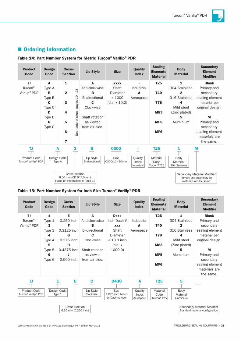
Turcon®Varilip®PDR
TRELLEBORG SEALING SOLUTIONS • 29Latest information available at www.tss.trelleborg.com • Edition May 2018
� Ordering InformationTable 14: Part number System for Metric Turcon®Varilip®PDR
Product Code
Design Code
Cross- Section
lip Style SizeQuality Index
Sealing Elements Material
Body Material
Secondary Element Modifier
TJTurcon®
Varilip®PDR
AType A
BType B
CType C
DType D
GType G
1
2
3
4
5
6
7
See
tab
le o
f si
zes,
pag
es 1
9 -
23
AAnti-clockwise
BBi-directional
CClockwise
Shaft rotation as viewed
from air side.
xxxxShaft
Diameter< 1000
(dia. x 10.0)
-Industrial
AAerospace
T25
T40
T78
M83
MF5
MF6
1304 Stainless
2316 Stainless
4Mild steel
(Zinc plated)5
Aluminium
BlankPrimary and secondary
sealing element material per
original design.
MPrimary and secondary
sealing element materials are
the same.
Product CodeTurcon® Varilip® PDR
TJ
Design CodeType A
A
Cross-section8.50 mm (OD Ø47.0 mm)
based on information in Table 12
3 -
Lip StyleBi-directional
B
Size0300/10=30mm
QualityIndex
Industrial
T25 1
MaterialCode
Turcon® T25
0300
BodyMaterial
304 Stainless
M
Secondary Material ModifierPrimary and secondary lip materials are the same
Table 15: Part number System for Inch Size Turcon®Varilip®PDR
Product Code
Design Code
Cross- Section
lip Style SizeQuality Index
Sealing Elements Material
Body Material
Secondary Element Modifier
TJTurcon®
Varilip®PDR
1Type 1
3Type 3
4Type 4
5Type 5
6Type 6
E0.250 inch
F0.3125 inch
G0.375 inch
H0.4375 inch
J0.500 inch
AAnti-clockwise
BBi-directional
CClockwise
Shaft rotation as viewed
from air side.
DxxxInch Dash #
xxxShaft
Diameter< 10.0 inch
(dia. x 1000.0)
-Industrial
AAerospace
T25
T40
T78
M83
MF5
MF6
1304 Stainless
2316 Stainless
4Mild steel
(Zinc plated)5
Aluminium
BlankPrimary and secondary
sealing element material per
original design.
MPrimary and secondary
sealing element materials are
the same.
Product CodeTurcon® Varilip® PDR
TJ
Design CodeType 1
1
Cross-Section6.35 mm (0.250 inch)
E A
Lip StyleClockwise
C
Size1.875 inch based on Dash number
QualityIndex
Aerospace
T25 5
MaterialCode
Turcon® T25
D430
BodyMaterialAluminium
Secondary Material ModifierStandard material configuration
TSS_Turcon_Varilip_PDR_2018.indd 29 14.05.2018 13:02:35

Turcon®Varilip®PDR
30 • TRELLEBORG SEALING SOLUTIONS Latest information available at www.tss.trelleborg.com • Edition May 2018
Notes
TSS_Turcon_Varilip_PDR_2018.indd 30 14.05.2018 13:02:35

Turcon®Varilip®PDR
TRELLEBORG SEALING SOLUTIONS • 31Latest information available at www.tss.trelleborg.com • Edition May 2018
Company name Agent/Salesman
Address Date
Company products
Application
Contacts Name Title Telephone Fax E-mail
Technical
Purchasing
Technical details Where available a sample or drawing of an existing seal is helpful but insufficient for aviable design to be produced unless accompanied by the following information.Include installation drawing or scheme wherever possible.
Shaft
Diameter, with tolerances mm/in
Speed range Maximum: Typical: Minimum: RPM
Direction of rotation (when viewed from air/low pressure side) Bi-directionalAnti-clockwiseClockwise
Material and treatment
Surface roughness µm Rz µm Ra
Hardness HRc
Dynamic eccentricity mm/in TIR
Static housing-to-shaft offset mm/in to center
Axial movement and frequency mm/in per
Shaft type at sealing pointHollow SleeveSolid Thickness mm/in
Housing
Diameter, with tolerances mm/in
Depth of recess mm/in
Speed range Maximum: Typical: Minimum: RPM
Direction of rotation (when viewed from air/low pressure side) Bi-directionalAnti-clockwiseClockwise
Housing type Axially split (split line will bisect seal OD) Homogeneous (no split line)
Material and treatment
Surface roughness µm Rz µm Rmax µm Ra
Hardness HRc
Environment
Type of fluid to be retained
Fluid level relative to shaft center line
Shaft orientation during normal operation Horizontal Vertical
Any other media seal may contact Other:Water splashDust/dirt
Working temperature ºC /ºF
Maximum and minimum temperatures ºC /ºF
Maximum and minimum pressure differential Bar Cycle Rate
Maximum test pressure Bar/psi
Is seal subject to pressure without shaft rotation Yes No
Purchasing details Note that this information will have an effect on the design solution offered. If actual data is unknown, please use estimations.
Drawing number (if available)
Would a test program be necessary Customer No Life Required
Type of release Aerospace Defense Industrial Specification
Annual usage Proportion we could expect
Rate of call off Supply commencement date
Prototype quantity Date prototypes required
TSS
TSS_Turcon_Varilip_PDR_2018.indd 31 14.05.2018 13:02:35

Turcon®Varilip®PDR
32 • TRELLEBORG SEALING SOLUTIONS Latest information available at www.tss.trelleborg.com • Edition May 2018
Notes
TSS_Turcon_Varilip_PDR_2018.indd 32 14.05.2018 13:02:35

TSS_Turcon_Varilip_PDR_2018_Cover.indd 3 14.05.2018 13:26:28

Trelleborg Se AlINg SolUTIoNS
yoUr pArTNer for Se AlINg TechNology
facebook.com/TrelleborgSealingSolutions
twitter.com/TrelleborgSeals
youtube.com/TrelleborgSeals
linkedin.com/company/trelleborg-sealing-solutions
If you’d like to talk to Trelleborg Sealing Solutions, fi nd your local contact at: www.tss.trelleborg.com/worldwide
Version no. 99
GB
TPC
ATEE051
8
WWW.TSS.TRELLEBORG.COM
Trelleborg is a world leader in engineered polymer solutions that seal, damp and protect critical applications in demanding environments. Its innovative solutions accelerate
performance for customers in a sustainable way.
Trelleborg Sealing Solutions is a leading developer, manufacturer and supplier of precision seals, bearings and custom-molded polymer components. It focuses on meeting the most demanding needs of aerospace, automotive and
general industrial customers with innovative solutions.
Copyright ©
20
18 Trelleborg A
B (publ). A
ll rights reserved. Information and related m
aterials are subject to change without notice.
TSS_Turcon_Varilip_PDR_2018_Cover.indd 4 14.05.2018 13:26:24