tut01 sw09 e excavator
TRANSCRIPT

Solidworks 2009 Overview – Toy Excavator
Non-Commercial UseVersion 2a- Jun2010 Written by Dickson Sham
A- 1
Solidworks 2009 Overview (Tutorial 1-Toy Excavator)
Infrastructure
Sketch
Solid Features
2D-Drawing
Surfaces
Assembly Design

Solidworks 2009 Overview – Toy Excavator
Non-Commercial UseVersion 2a- Jun2010 Written by Dickson Sham
A- 2
Solidworks Overview
Tutorial 1A
- Solidworks Infrastructure
- Sketch
- Solid Features
- 2D-Drawing (projected from 3D)
- Auto-Update
Tutorial 1B
- Solid Features
- Surfaces
- Real-time rendering & Material Mapping
Tutorial 1C
- Assembly Design
- Clash Detection & Part Modification
Please be reminded that this series of tutorials is designed to demonstrate a
design approach with Solidworks, rather than the command itself.

Solidworks 2009 Overview – Toy Excavator
Non-Commercial UseVersion 2a- Jun2010 Written by Dickson Sham
A- 3
Tutorial 1A
• Enter Solidworks 2009 by double-clicking
its icon on the desktop.
• Select “File/New…” on the top menu
• Click “Part” and then OK
• (A new file is created; an empty part tree
appears on the left; Front, Top & Right
Planes are hidden by default)
• Select “View/Origins” on the top menu
• (A blue dot appears on the working area,
which is the system origin)
Not For Commercial Use

Solidworks 2009 Overview – Toy Excavator
Non-Commercial UseVersion 2a- Jun2010 Written by Dickson Sham
A- 4
Change the view with the mouse
A. Rotating enables you to rotate
the model around a point. Click
and hold the middle mouse button,
then drag the mouse.
B. Panning enables you to move the
model on a plane parallel to the
screen. Press and hold “Ctrl” key,
then click and hold the middle
mouse button, then drag the
mouse.
C. Zooming enables you to increase
or decrease the size of the model.
Press and hold “Shift” key, then
click and hold the middle button,
then drag the mouse up or down.
Middle button
General

Solidworks 2009 Overview – Toy Excavator
Non-Commercial UseVersion 2a- Jun2010 Written by Dickson Sham
A- 5
Tutorial 1ATo reset the layout of workbench:-
• Sometimes the workbench may not be tidy before you
use; some toolbars are missing and some are at
wrong positions. To reset the layout, select
“View/Toolbars/Customize…” on the menu bar and
select “Reset” on the first tab page.
• Check “Enable CommandManager”
• (Visible toolbars have a tick next to them)
• (The toolbar “Surfaces” is hidden by default; we can
find all commands on the top menu bar)

Solidworks 2009 Overview – Toy Excavator
Non-Commercial UseVersion 2a- Jun2010 Written by Dickson Sham
A- 6
Tutorial 1A
To build 1st sketch:-
• Select tab page “Sketch” to show all common icons
related to “Sketch”
• click “Sketch” icon (1st icon) and select Front Plane
• Now the display is temporarily switched to the sketcher
mode, in which you can draw 2D elements on the
selected plane. (The viewpoint is changed automatically
so that the plane’s normal is pointing directly to you)
• Draw a circle at the origin. 1st click is to define the
centre and 2nd click is to define the radius. (no need to
care too much about the position of 2nd click, we will
define the radius later)
Features
ON
Sketch
ON

Solidworks 2009 Overview – Toy Excavator
Non-Commercial UseVersion 2a- Jun2010 Written by Dickson Sham
A- 7
Tutorial 1A• To deactivate “Circle” command, press “Esc” on the
keyboard
• (A coincident relation is created automatically and
appears at the circle center; if you cannot see it, select
“View/Sketch Relations” to make it visible)
• Add a dimension onto the circle by clicking “Smart
Dimension” icon and then selecting the circle.
• Click on an open area to place the dimension
• Enter 10mm in the entry box and then press “Enter” on
the keyboard; the circle will be resized automatically.
• Exit the sketch mode by clicking “Exit Sketch” icon
• Now, you are back to the 3D environment and “Sketch1”
is created on the tree.

Solidworks 2009 Overview – Toy Excavator
Non-Commercial UseVersion 2a- Jun2010 Written by Dickson Sham
A- 8
Tutorial 1ATo build 2nd sketch:-
• Click somewhere near the circle to deselect Sketch1.
(The circle color is then changed from blue to gray)
• Click “Sketch” icon again and select Front Plane on
the tree
• Draw a circle on the left of the previous circle. With
the help of auto-detection, you can define the center
on the x-axis. (no need to care too much about the
size and the position, we will define later).
• To deactivate “Circle” command, press “Esc” on
the keyboard
• Click “Smart Dimension” icon and select the circle.
Modify its diameter as 17mm and then press “Enter”
on the keyboard to confirm.
• Select the two circle centers. Modify the distance as
84mm. (You will see that only the current circle will
move correspondingly. Remark: you cannot modify
any element that does not belong to this sketch.)
• Exit the sketch mode by clicking “Exit Sketch” icon
• (You can see “Sketch2” on the tree.)
Tree appears in
working area
Solidworks 2009 Overview – Toy Excavator
Non-Commercial UseVersion 2a- Jun2010 Written by Dickson Sham
A- 9
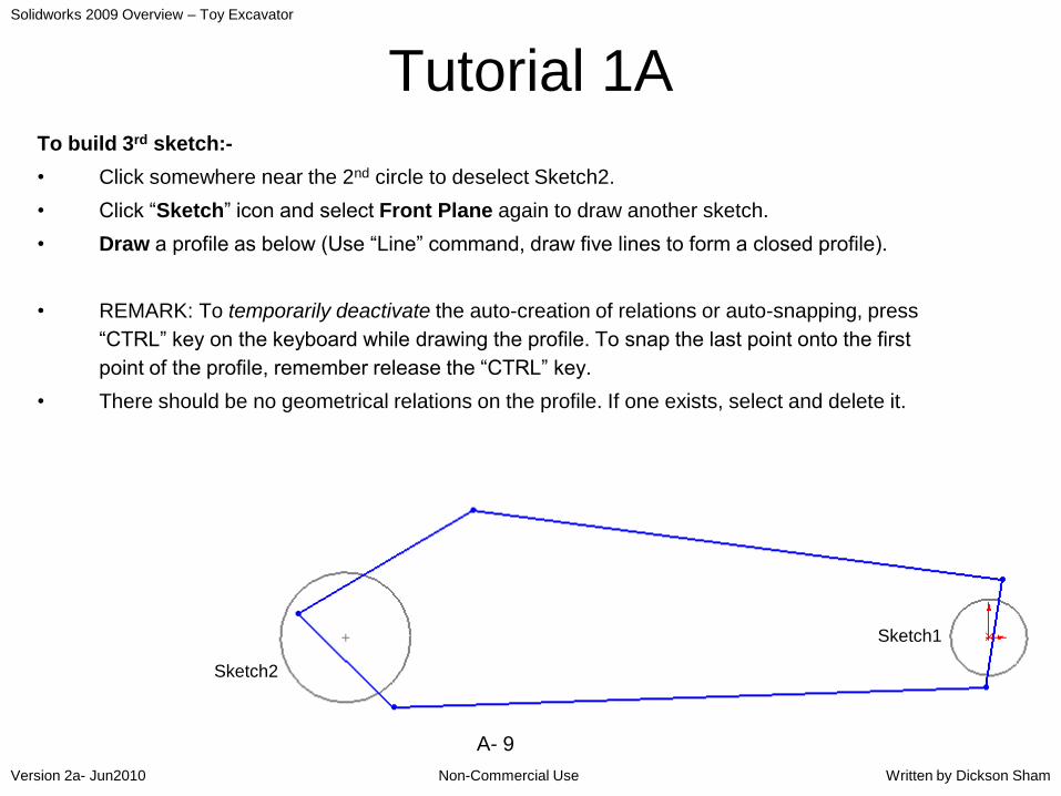
Tutorial 1ATo build 3rd sketch:-
• Click somewhere near the 2nd circle to deselect Sketch2.
• Click “Sketch” icon and select Front Plane again to draw another sketch.
• Draw a profile as below (Use “Line” command, draw five lines to form a closed profile).
• REMARK: To temporarily deactivate the auto-creation of relations or auto-snapping, press
“CTRL” key on the keyboard while drawing the profile. To snap the last point onto the first
point of the profile, remember release the “CTRL” key.
• There should be no geometrical relations on the profile. If one exists, select and delete it.
Sketch2
Sketch1

Solidworks 2009 Overview – Toy Excavator
Non-Commercial UseVersion 2a- Jun2010 Written by Dickson Sham
A- 10
Tutorial 1A
• (To ensure the lines are tangent to the small circle,
we need to add a tangency relation between them)
• Multi-select the upper line and the small circle by
pressing and holding “ctrl” key on the keyboard.
Select “Tangent”.
• Multi-select the endpoint of the line and the small
circle by pressing and holding “ctrl” key on the
keyboard. Select “Coincident”.
• (No need to click “Close Dialog”)
• Multi-select the lower line and the small circle by
pressing and holding “ctrl” key on the keyboard.
Select “Tangent”.
• Multi-select the endpoint of the line and the small
circle by pressing and holding “ctrl” key on the
keyboard. Select “Coincident”.
• (No need to click “Close Dialog”)
Tangent &
Coincident
Tangent &
Coincident

Solidworks 2009 Overview – Toy Excavator
Non-Commercial UseVersion 2a- Jun2010 Written by Dickson Sham
A- 11
Tutorial 1A• Multi-select the endpoint of the lower line and the big circle by pressing
and holding “ctrl” key on the keyboard.
• Select “Coincident”.
• (No need to click “Close Dialog”)
• Continue to add the dimensions as shown so that the profile is fully-
constrained.
• Exit Sketch after it is complete.
• Now, you should have Sketch1, Sketch2 and Sketch3 on the tree.
Tangent &
coincident
Tangent &
coincident
Coincident
only
Big
circle
Coincident
Solidworks 2009 Overview – Toy Excavator
Non-Commercial UseVersion 2a- Jun2010 Written by Dickson Sham
A- 12
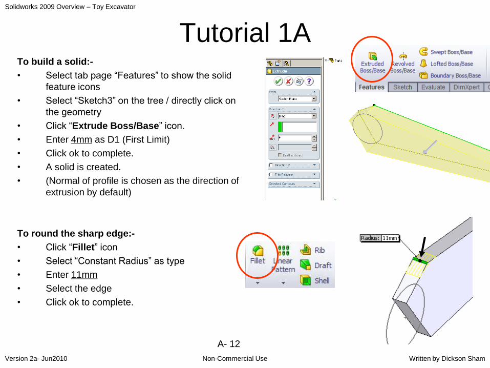
Tutorial 1ATo build a solid:-
• Select tab page “Features” to show the solid
feature icons
• Select “Sketch3” on the tree / directly click on
the geometry
• Click “Extrude Boss/Base” icon.
• Enter 4mm as D1 (First Limit)
• Click ok to complete.
• A solid is created.
• (Normal of profile is chosen as the direction of
extrusion by default)
To round the sharp edge:-
• Click “Fillet” icon
• Select “Constant Radius” as type
• Enter 11mm
• Select the edge
• Click ok to complete.
Solidworks 2009 Overview – Toy Excavator
Non-Commercial UseVersion 2a- Jun2010 Written by Dickson Sham
A- 13
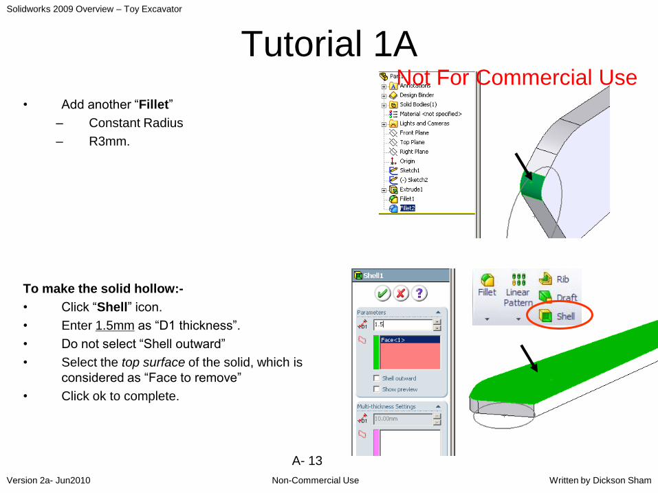
Tutorial 1A
• Add another “Fillet”
– Constant Radius
– R3mm.
To make the solid hollow:-
• Click “Shell” icon.
• Enter 1.5mm as “D1 thickness”.
• Do not select “Shell outward”
• Select the top surface of the solid, which is
considered as “Face to remove”
• Click ok to complete.
Not For Commercial Use

Solidworks 2009 Overview – Toy Excavator
Non-Commercial UseVersion 2a- Jun2010 Written by Dickson Sham
A- 14
Tutorial 1A• (You should now have a model as shown on the
right; all the wall thickness is 1.5mm, and the
top cover is removed.)
To build 2 more Extruded Bosses:-
• Click “Extruded Boss/Base” icon
• Select “Sketch1”
• Enter 7mm as D1
• (option “merge result” is selected by default)
• Click ok to complete.
Similarly,
• Click “Extruded Boss/Base” icon again
• Select “Sketch2”
• Enter 6mm as D1.
• Click ok to complete.
Sketch1,
7mm
Sketch2,
6mm
Solidworks 2009 Overview – Toy Excavator
Non-Commercial UseVersion 2a- Jun2010 Written by Dickson Sham
A- 15
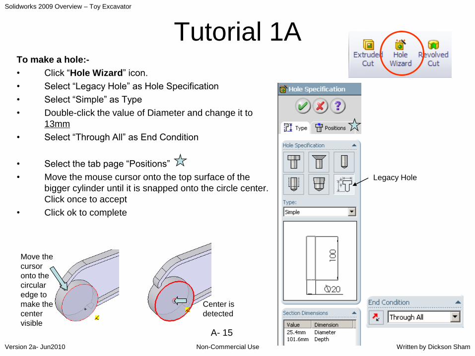
Tutorial 1ATo make a hole:-
• Click “Hole Wizard” icon.
• Select “Legacy Hole” as Hole Specification
• Select “Simple” as Type
• Double-click the value of Diameter and change it to
13mm
• Select “Through All” as End Condition
• Select the tab page “Positions”
• Move the mouse cursor onto the top surface of the
bigger cylinder until it is snapped onto the circle center.
Click once to accept
• Click ok to complete
Legacy Hole
Center is
detected
Move the
cursor
onto the
circular
edge to
make the
center
visible

Solidworks 2009 Overview – Toy Excavator
Non-Commercial UseVersion 2a- Jun2010 Written by Dickson Sham
A- 16
Tutorial 1A
• Make another hole Dia 6mm on the smaller
cylinder in the same way…
To Duplicate another half:-
• Click “Mirror” icon and select Front Plane or the
bottom planar face as Mirror Plane
• Click the entry box under “Bodies to Mirror”
• Select the solid
• Click ok to complete
Hole D6mm,
Through all

Solidworks 2009 Overview – Toy Excavator
Non-Commercial UseVersion 2a- Jun2010 Written by Dickson Sham
A- 17
Tutorial 1ATo build a sketch (open profile):-
• Click “Sketch” icon and select “Front Plane”
• Press “Space” key on the keyboard and double-
click “Normal to” on the popup list
• Draw a horizontal line as shown
• (No need to specify its length, long enough to cut
across the solid wall)
• Click “Exit Sketch” icon to exit.
To remove material with an open profile:-
• Click “Extruded Cut” icon
• Select “Through All” for both Direction 1 & 2
• Select “Thin Feature” and then “Mid-Plane”
• Enter 4.4mm as T1
• Click ok to complete

Solidworks 2009 Overview – Toy Excavator
Non-Commercial UseVersion 2a- Jun2010 Written by Dickson Sham
A- 18
Tutorial 1ASimilarly, to build another sketch (open profile):-
• Click “Sketch” icon and select “Front Plane”
• Draw an inclined line
• If necessary, Add a “concentric” relation to ensure that the
endpoint is at the circle center
• Draw a horizontal centerline from the circle center
• Inclined angle =45 deg from the axis.
• (No need to specify its length.)
• Click “Exit Sketch” icon to exit.
To remove material with an open profile:-
• Click “Extruded Cut” icon
• Select “Through All” for both first direction & second
direction
• Select “Thin Feature” and then “Mid-Plane”
• Enter 11.6mm as T1
• Click ok to complete

Solidworks 2009 Overview – Toy Excavator
Non-Commercial UseVersion 2a- Jun2010 Written by Dickson Sham
A- 19
Tutorial 1ATo build a new sketch:-
• Click “Sketch” icon and select “Front Plane”
• Draw a closed profile as shown.
• Add dimensions & relations.
• Click “Exit Sketch” to complete.
Draw this line first, with
help of auto-detection; it
should be coincident with
the solid surface
Auto-Snapping can help creating
parallel/perpendicular lines
Not For Commercial Use
Solidworks 2009 Overview – Toy Excavator
Non-Commercial UseVersion 2a- Jun2010 Written by Dickson Sham
A- 20
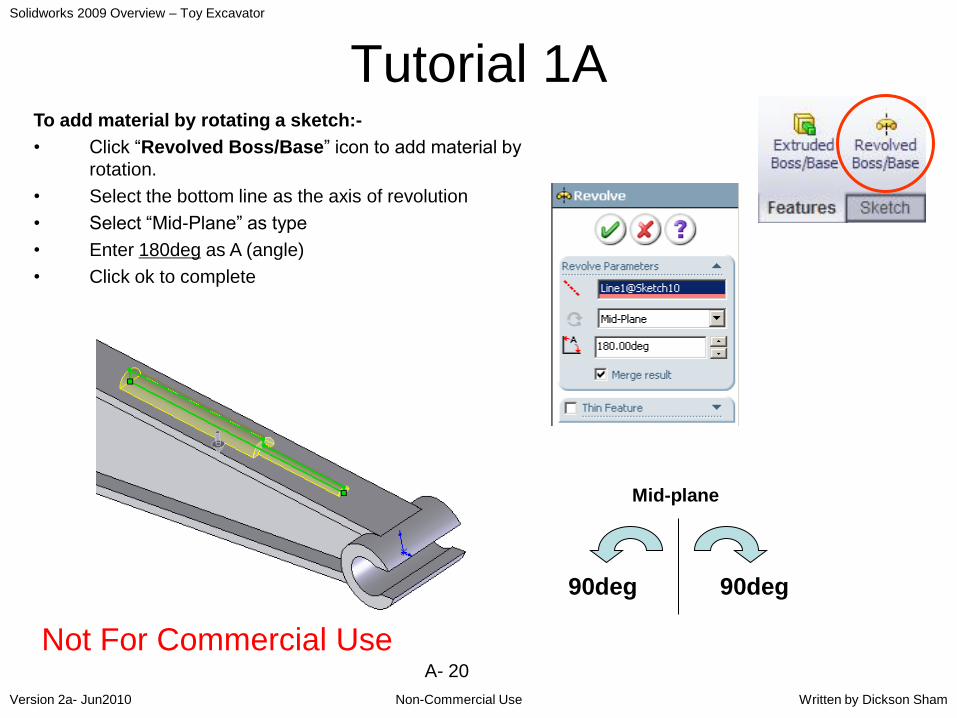
Tutorial 1ATo add material by rotating a sketch:-
• Click “Revolved Boss/Base” icon to add material by
rotation.
• Select the bottom line as the axis of revolution
• Select “Mid-Plane” as type
• Enter 180deg as A (angle)
• Click ok to complete
Mid-plane
90deg 90deg
Not For Commercial Use
Solidworks 2009 Overview – Toy Excavator
Non-Commercial UseVersion 2a- Jun2010 Written by Dickson Sham
A- 21
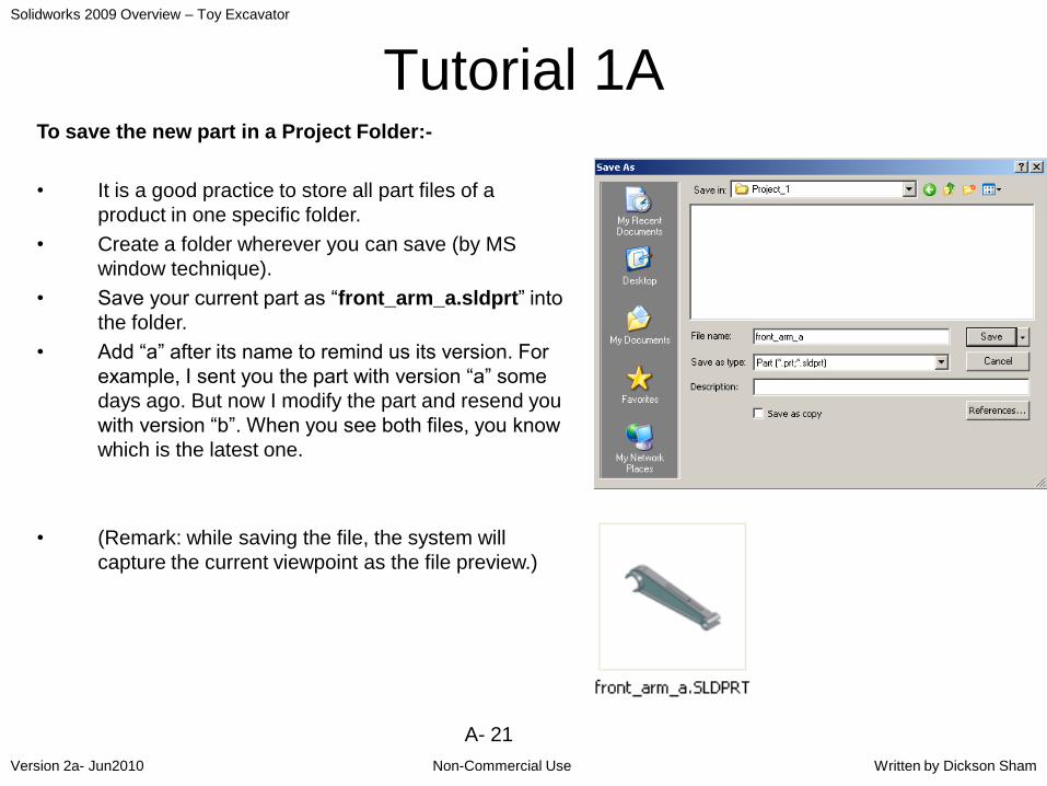
Tutorial 1ATo save the new part in a Project Folder:-
• It is a good practice to store all part files of a
product in one specific folder.
• Create a folder wherever you can save (by MS
window technique).
• Save your current part as “front_arm_a.sldprt” into
the folder.
• Add “a” after its name to remind us its version. For
example, I sent you the part with version “a” some
days ago. But now I modify the part and resend you
with version “b”. When you see both files, you know
which is the latest one.
• (Remark: while saving the file, the system will
capture the current viewpoint as the file preview.)
Solidworks 2009 Overview – Toy Excavator
Non-Commercial UseVersion 2a- Jun2010 Written by Dickson Sham
A- 22
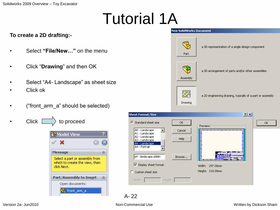
Tutorial 1ATo create a 2D drafting:-
• Select “File/New…” on the menu
• Click “Drawing” and then OK
• Select “A4- Landscape” as sheet size
• Click ok
• (“front_arm_a” should be selected)
• Click to proceed

Solidworks 2009 Overview – Toy Excavator
Non-Commercial UseVersion 2a- Jun2010 Written by Dickson Sham
A- 23
Tutorial 1A
• Select “Multiple Views”
• Click the icons “Left” & “Top”
• Click ok to complete (Green Arrow)
To define the projection angle:-
• Right-click “Sheet1” on the tree
• Select “Properties…”
• Select “Third Angle” as Type of Projection
• Click ok to complete
• (All views are updated, according to the
new projection)
Left
Top

Solidworks 2009 Overview – Toy Excavator
Non-Commercial UseVersion 2a- Jun2010 Written by Dickson Sham
A- 24
Tutorial 1ATo move a view:-
• Move the mouse cursor near the view until
you can see this symbol
• Drag the view to the desired location
• (The related views will also be moved
automatically so that the projection
directions are kept unchanged)
To add a projection view:-
• Select “Insert / Drawing View / Projected”
on the menu bar
• Click on the front view and then drag
upward to create a projection view on the
top
• Click once to complete
• Press “Esc” on the keyboard
Drag down
Click on the front view and
then drag upward to
create a projection view
on top

Solidworks 2009 Overview – Toy Excavator
Non-Commercial UseVersion 2a- Jun2010 Written by Dickson Sham
A- 25
Tutorial 1ATo add an isomeric view (user-defined):-
• Select “window/front_arm_a.sldprt” to view the
3D part.
• Rotate the part to the desired orientation
• Press “Space” key on the keyboard
• Click “New View” icon to save the current view
orientation
• Enter a View Name and click ok
• Select “window/front_arm_a – SHEET1” to view
the 2D drawing
• Select “Insert / Drawing View / Model…” on the
menu bar
• Click “Next” icon
• Select “Single View”
• Select the newly-created view (under “more
views…”)
• Click an empty space on the drawing
• Click yes to accept true iso dimensions
• Click ok to complete
New View
Save the view
orientation

Solidworks 2009 Overview – Toy Excavator
Non-Commercial UseVersion 2a- Jun2010 Written by Dickson Sham
A- 26
Tutorial 1ASelect File/Save…
Enter “Front_arm_a.slddrw”
Click yes to save the 3D file too
Now you have two files:-
• Front_arm_a.sldprt
• Front_arm_a.slddrw
• The drawing is created from the part
file, and so if the part is changed, the
drawing will change automatically.
• Now try to modify the 3D.
• Go back to the drawing to see whether
the views have been updated
correspondingly.
• Close both files without saving.
END of Tutorial 1A
Not For Commercial Use

Solidworks 2009 Overview – Toy Excavator
Non-Commercial UseVersion 2a- Jun2010 Written by Dickson Sham
A- 27
Summary of Tut-1ABuild a Sketch:-
1. Click “Sketch” Icon
2. Select a plane
3. Draw a profile (with lines, curves and/or
centerlines)
4. Add geometrical constraints (relations)
5. Add dimensional constraints & modify the
values
6. Click “Exit Sketch” icon

Solidworks 2009 Overview – Toy Excavator
Non-Commercial UseVersion 2a- Jun2010 Written by Dickson Sham
A- 28
Summary of Tut-1ABuild a Solid:-
Extruded
Base
Revolved
Base
Mirror Hole Extruded
Base
Shell
FilletSketch
Extruded
Cut
Extruded
Cut
Create a 2D
drawing &
get drawing
update after
3D change

Solidworks 2009 Overview – Toy Excavator
Non-Commercial UseVersion 2a- Jun2010 Written by Dickson Sham
A- 29
Tutorial 1BContinuing what we learnt in Tutorial 1A, we are going to
build the cabinet by the solid-modeling technique plus
some surface modeling technique…
• Enter Solidworks 2009
• Select “File/New…” on the menu
• Click “Part” and then OK
To build a sketch:-
• Click “Sketch” icon and select Front Plane.
• Draw a rectangle (47mm x 31mm) as shown; one edge is
aligned on x-axis
• Draw a centerline along y-axis
• Multi-select two vertical sides and then the centerline by
pressing and holding “CTRL” key
• Select “Symmetric” relation
• Click ok
• Exit Sketch.
System
origin

Solidworks 2009 Overview – Toy Excavator
Non-Commercial UseVersion 2a- Jun2010 Written by Dickson Sham
A- 30
Tutorial 1B
To build a solid:-
• Click “Extruded Boss/Base” icon.
• Enter 38mm as D1 (First Limit).
• Click ok to complete.
To build 2nd sketch:-
• Click “Sketch” icon and select Right Plane (on tree).
• Press “Space” key on the keyboard and double-click
“Normal to” on the popup list
• Draw a line 8mm as shown; it is aligned onto the solid
edge and one endpoint touches y-axis.
• Draw a tangent arc R35
• Exit Sketch
• Click on an open area to deselect “Sketch2”
A line
origin
Solidworks 2009 Overview – Toy Excavator
Non-Commercial UseVersion 2a- Jun2010 Written by Dickson Sham
A- 31
Tutorial 1B
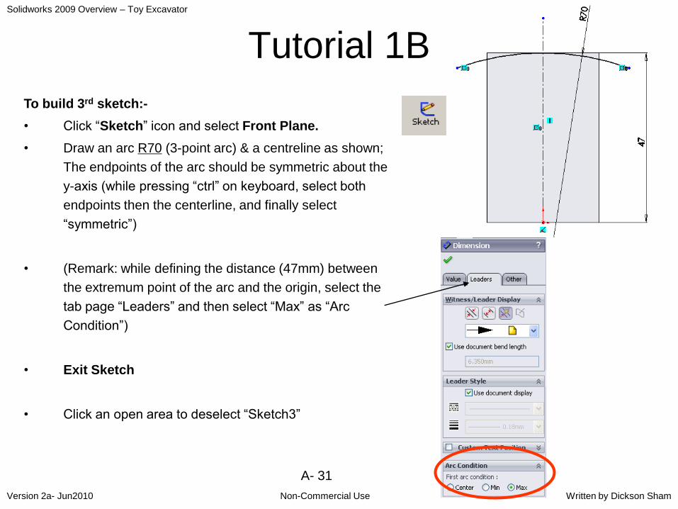
To build 3rd sketch:-
• Click “Sketch” icon and select Front Plane.
• Draw an arc R70 (3-point arc) & a centreline as shown;
The endpoints of the arc should be symmetric about the
y-axis (while pressing “ctrl” on keyboard, select both
endpoints then the centerline, and finally select
“symmetric”)
• (Remark: while defining the distance (47mm) between
the extremum point of the arc and the origin, select the
tab page “Leaders” and then select “Max” as “Arc
Condition”)
• Exit Sketch
• Click an open area to deselect “Sketch3”

Solidworks 2009 Overview – Toy Excavator
Non-Commercial UseVersion 2a- Jun2010 Written by Dickson Sham
A- 32
Tutorial 1BTo build a SURFACE:-
• Select “Insert /Surface/ Sweep” on
the menu bar
• Select “Sketch3” as Profile
• Select “Sketch2” as Path
• Press “Enter” key to complete
On the tree, this surface is stored in
“Surface Bodies”, so it will not be
mixed with solids.
Sketch2,
Path
Sketch1,
Profile
Not For Commercial Use
Solidworks 2009 Overview – Toy Excavator
Non-Commercial UseVersion 2a- Jun2010 Written by Dickson Sham
A- 33
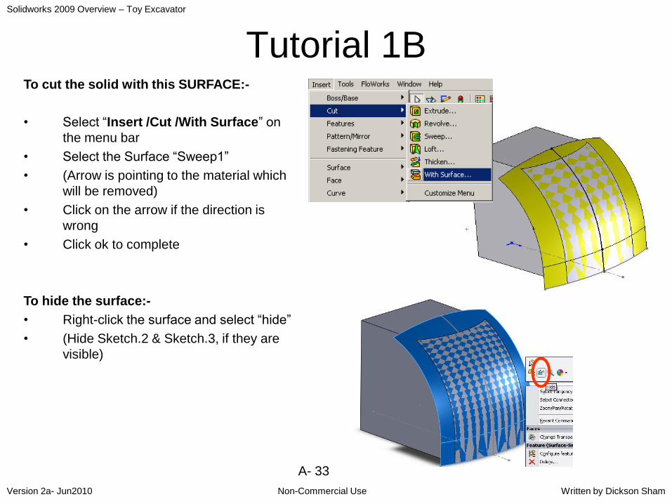
Tutorial 1BTo cut the solid with this SURFACE:-
• Select “Insert /Cut /With Surface” on
the menu bar
• Select the Surface “Sweep1”
• (Arrow is pointing to the material which
will be removed)
• Click on the arrow if the direction is
wrong
• Click ok to complete
To hide the surface:-
• Right-click the surface and select “hide”
• (Hide Sketch.2 & Sketch.3, if they are
visible)

Solidworks 2009 Overview – Toy Excavator
Non-Commercial UseVersion 2a- Jun2010 Written by Dickson Sham
A- 34
Tutorial 1B
Add a “Fillet” R3mm as shown:-
• Select the two vertical edges
• Select “Constant Radius” as type
• Enter 3mm as radius
Add a “Chamfer” onto the edges as shown:-
• Select “Angle Direction” as mode.
• Enter 2mm as D (Distance)
• Enter 45deg as A (Angle)
• Select “Tangency Propagation”
• Click 3 edges at
Solidworks 2009 Overview – Toy Excavator
Non-Commercial UseVersion 2a- Jun2010 Written by Dickson Sham
A- 35
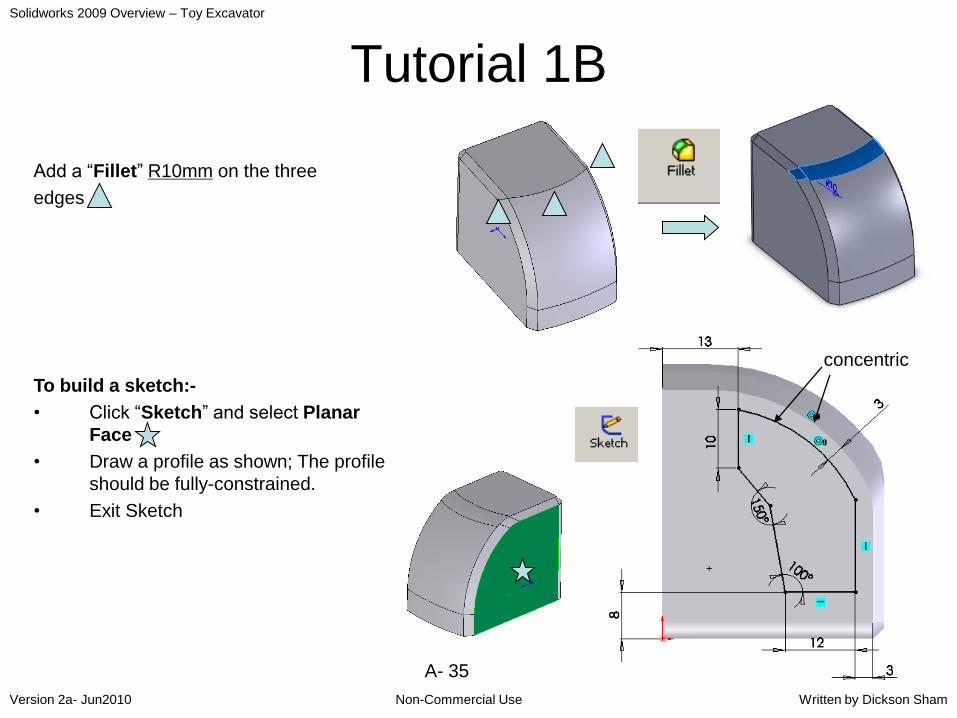
Tutorial 1B
Add a “Fillet” R10mm on the three
edges
To build a sketch:-
• Click “Sketch” and select Planar
Face .
• Draw a profile as shown; The profile
should be fully-constrained.
• Exit Sketch
concentric
Solidworks 2009 Overview – Toy Excavator
Non-Commercial UseVersion 2a- Jun2010 Written by Dickson Sham
A- 36
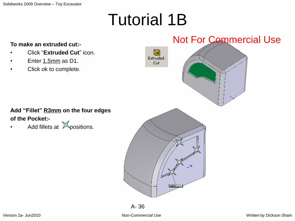
Tutorial 1B
To make an extruded cut:-
• Click “Extruded Cut” icon.
• Enter 1.5mm as D1.
• Click ok to complete.
Add “Fillet” R3mm on the four edges
of the Pocket:-
• Add fillets at positions.
Not For Commercial Use

Solidworks 2009 Overview – Toy Excavator
Non-Commercial UseVersion 2a- Jun2010 Written by Dickson Sham
A- 37
Tutorial 1BTo add a Draft onto the side faces of the cut:-
• Click “Draft” icon
• Click “Manual” icon on the command menu
• Select “Neutral Plane” as Type
• Enter 50deg as Draft Angle
• Select the bottom face as “Neutral Element”
• Select the lower side face as “Faces to draft”
• Select “Along Tangent” as Face Propagation
• Click the arrow once if it is not pointing outward
• Click ok to complete

Solidworks 2009 Overview – Toy Excavator
Non-Commercial UseVersion 2a- Jun2010 Written by Dickson Sham
A- 38
Tutorial 1BTo add another Draft onto the side faces of
the cut:-
• Click “Draft” icon
• Click “Manual”
• Select “Neutral Plane” as Type
• Enter 30deg as Draft Angle
• Select the bottom face as “Neutral Element”
• Select the upper side face as “Faces to draft”
• Select “Along Tangent” as Face Propagation
• Click the arrow once if it is not pointing
outward
• Click ok to complete
(Now you should have two drafts on the cut.)
Draft.2
Draft.1
Not For Commercial Use

Solidworks 2009 Overview – Toy Excavator
Non-Commercial UseVersion 2a- Jun2010 Written by Dickson Sham
A- 39
Tutorial 1BAdd “Fillet” R1mm on the remaining
two edges of the Cut at positions.
To create an offset reference plane:-
• Click “Reference Geometry” icon, then
“Plane”
• Select Top Plane (on tree)
• Enter 70mm as D (Offset Value)
• Click ok to complete
(Now a new plane is created in front of the solid,
which is stored on the tree.)

Solidworks 2009 Overview – Toy Excavator
Non-Commercial UseVersion 2a- Jun2010 Written by Dickson Sham
A- 40
Tutorial 1B
To build a sketch on the offset plane:-
• Click “Sketch” icon and select “Plane1”.
• Draw a rectangle (24x25) and position it as
shown
• Draw a centerline along y-axis
• Multi-select two vertical sides and then the
centerline by pressing and holding “CTRL” key
• Select “Symmetric” relation
• Exit Sketch.
sketch
Plane.1
Solidworks 2009 Overview – Toy Excavator
Non-Commercial UseVersion 2a- Jun2010 Written by Dickson Sham
A- 41
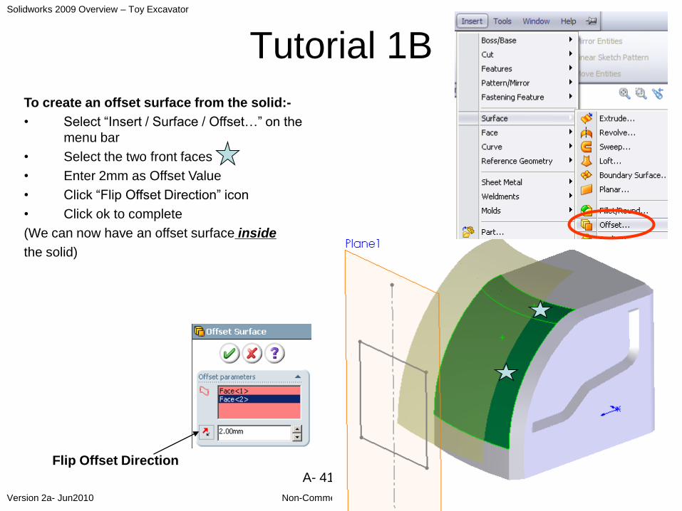
Tutorial 1B
To create an offset surface from the solid:-
• Select “Insert / Surface / Offset…” on the
menu bar
• Select the two front faces
• Enter 2mm as Offset Value
• Click “Flip Offset Direction” icon
• Click ok to complete
(We can now have an offset surface inside
the solid)
Flip Offset Direction
Solidworks 2009 Overview – Toy Excavator
Non-Commercial UseVersion 2a- Jun2010 Written by Dickson Sham
A- 42
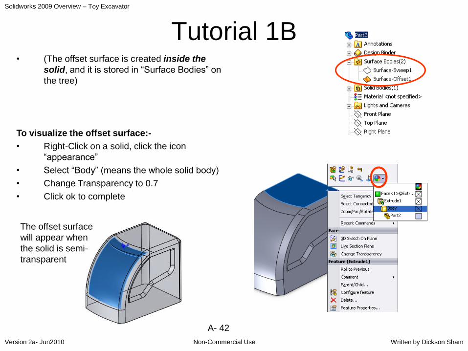
Tutorial 1B• (The offset surface is created inside the
solid, and it is stored in “Surface Bodies” on
the tree)
To visualize the offset surface:-
• Right-Click on a solid, click the icon
“appearance”
• Select “Body” (means the whole solid body)
• Change Transparency to 0.7
• Click ok to complete
The offset surface
will appear when
the solid is semi-
transparent
Solidworks 2009 Overview – Toy Excavator
Non-Commercial UseVersion 2a- Jun2010 Written by Dickson Sham
A- 43
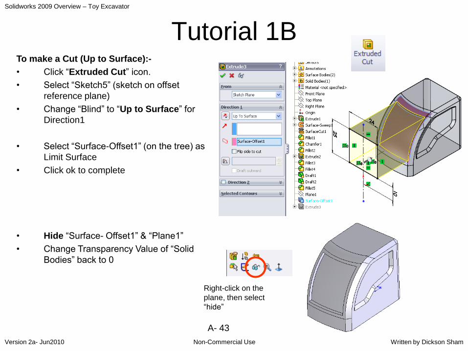
Tutorial 1BTo make a Cut (Up to Surface):-
• Click “Extruded Cut” icon.
• Select “Sketch5” (sketch on offset
reference plane)
• Change “Blind” to “Up to Surface” for
Direction1
• Select “Surface-Offset1” (on the tree) as
Limit Surface
• Click ok to complete
• Hide “Surface- Offset1” & “Plane1”
• Change Transparency Value of “Solid
Bodies” back to 0
Right-click on the
plane, then select
“hide”

Solidworks 2009 Overview – Toy Excavator
Non-Commercial UseVersion 2a- Jun2010 Written by Dickson Sham
A- 44
Tutorial 1B
Add “Fillet” R1mm at 2 corners of
“Extrude.3” at positions
To split the solid into a half:-
• Select “Insert/ Cut /With Surface” on the
menu bar
• Select “Right Plane”
• (Arrow should be pointing to the side
without a “window”; If not, click on it to
change the direction)
• Click ok to complete
To create another half by mirroring:-
• Click “Mirror” icon.
• Select the cut face as Mirror Plane
• Click on “Bodies to mirror”
• Select the solid
• Click ok to complete
Extrude.3
Not For Commercial Use

Solidworks 2009 Overview – Toy Excavator
Non-Commercial UseVersion 2a- Jun2010 Written by Dickson Sham
A- 45
Tutorial 1BTo remove material along a guide:-
• Click “Sketch” icon and select Right Plane
• Draw a circle D1.5mm; 5mm from the origin, &
circle center is aligned on the axis
• Exit Sketch
• Select “Insert/ Curve/ Composite” on the menu
• Select the three edges
• Click ok to complete
Join them
into one

Solidworks 2009 Overview – Toy Excavator
Non-Commercial UseVersion 2a- Jun2010 Written by Dickson Sham
A- 46
Tutorial 1B• Click “Swept Cut”
• Select “Sketch6” as Profile
• Select “CompCurve1” as Path
• (“aligned with end faces” should be selected by
default, under “Options”)
• Click ok to complete
(Remark: This is a limitation of solidworks
2009 that the cut must always start from
“Profile”. Also, sweeping only happens in
one direction)
(Remark: When “aligned with end faces”
is selected, the cut will go through the
solid, even though the path is not long
enough)

Solidworks 2009 Overview – Toy Excavator
Non-Commercial UseVersion 2a- Jun2010 Written by Dickson Sham
A- 47
Tutorial 1BTo create another half by mirroring:-
• Click “Mirror” icon.
• Select “Right Plane” as Mirror Plane
• Click on “Features to mirror”
• Select “Cut-Sweep1”
• Press Enter key to complete
Add “Fillet” R1.0mm on the edges on
both sides, except those of the front cut.
Add “Fillet” R1.0mm on the edges of
the front cut.
• Sometimes, we need to build fillets separately
when the sharp edges are too close to each other.
We need to build a fillet on one edge first, and
then build another one on top of it.
Not For Commercial Use

Solidworks 2009 Overview – Toy Excavator
Non-Commercial UseVersion 2a- Jun2010 Written by Dickson Sham
A- 48
Tutorial 1BTo change color properties of the model:-
• Right-Click on a solid face, then click icon
“appearance”
• Select “Body” on the list
• Change color as Red 60, Green 60, Blue 60
• Change “Specular” to 0.3
• Change “Shininess” to 0.3
• Click ok to complete
• Right-Click on the front face , click icon
“appearance”
• Select “Face” on the list
• Click “Browse…” under “Appearance”
• Select “materials/metal/chrome/chromium
plate.p2m”
• Click ok to complete
Save the file as “Cabinet_a.sldprt” in your project
folder and then close it.
Solidworks 2009 Overview – Toy Excavator
Non-Commercial UseVersion 2a- Jun2010 Written by Dickson Sham
A- 49
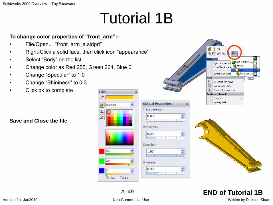
Tutorial 1BTo change color properties of “front_arm”:-
• File/Open… “front_arm_a.sldprt”
• Right-Click a solid face, then click icon “appearance”
• Select “Body” on the list
• Change color as Red 255, Green 204, Blue 0
• Change “Specular” to 1.0
• Change “Shininess” to 0.3
• Click ok to complete
Save and Close the file
END of Tutorial 1B

Solidworks 2009 Overview – Toy Excavator
Non-Commercial UseVersion 2a- Jun2010 Written by Dickson Sham
A- 50
Summary of Tut-1BBuild a Solid:-
Create a
Surface
Cut-Sweep
Draft Fillet Fillet
ChamferCut by SurfaceExtruded
Base
Mirror
Body
Cut up to
surface
Extruded Cut
Fillet
Mirror- Feature Fillet
Solidworks 2009 Overview – Toy Excavator
Non-Commercial UseVersion 2a- Jun2010 Written by Dickson Sham
A- 51
Tutorial 1C
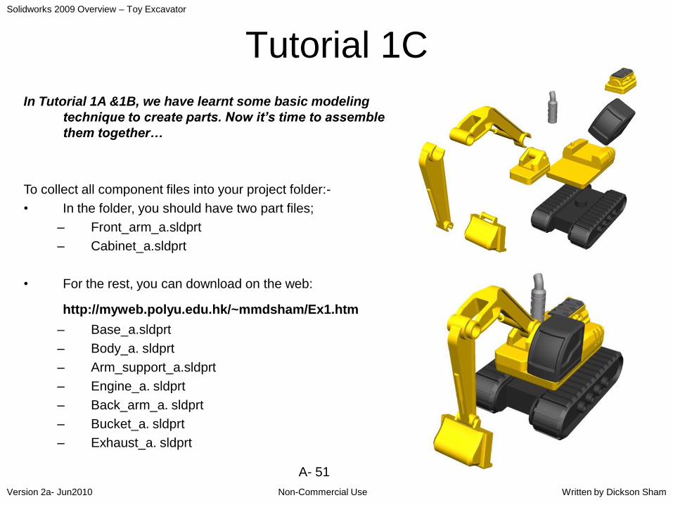
In Tutorial 1A &1B, we have learnt some basic modeling
technique to create parts. Now it’s time to assemble
them together…
To collect all component files into your project folder:-
• In the folder, you should have two part files;
– Front_arm_a.sldprt
– Cabinet_a.sldprt
• For the rest, you can download on the web:
http://myweb.polyu.edu.hk/~mmdsham/Ex1.htm
– Base_a.sldprt
– Body_a. sldprt
– Arm_support_a.sldprt
– Engine_a. sldprt
– Back_arm_a. sldprt
– Bucket_a. sldprt
– Exhaust_a. sldprt

Solidworks 2009 Overview – Toy Excavator
Non-Commercial UseVersion 2a- Jun2010 Written by Dickson Sham
A- 52
Tutorial 1C
• Enter Solidworks
• Close all files
• Select “File/New…” on the menu
• Click “Assembly” and then OK
To insert existing parts into the assembly:-
• Click “Browse…”
• Select the file “Body_a.sldprt”
• Click “Open”
• Click ok to complete
(part’s origin will be aligned onto
assembly’s origin)
The first
component is fixed
in position by
default; (f) = (fixed)
Not For Commercial Use
Solidworks 2009 Overview – Toy Excavator
Non-Commercial UseVersion 2a- Jun2010 Written by Dickson Sham
A- 53
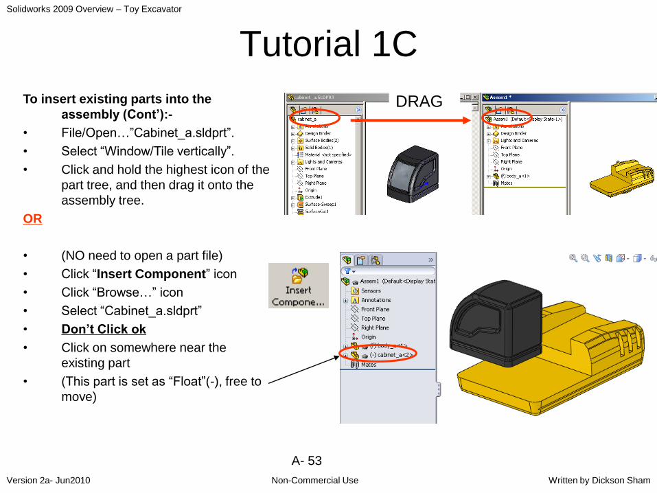
Tutorial 1C
To insert existing parts into the
assembly (Cont’):-
• File/Open…”Cabinet_a.sldprt”.
• Select “Window/Tile vertically”.
• Click and hold the highest icon of the
part tree, and then drag it onto the
assembly tree.
OR
• (NO need to open a part file)
• Click “Insert Component” icon
• Click “Browse…” icon
• Select “Cabinet_a.sldprt”
• Don’t Click ok
• Click on somewhere near the
existing part
• (This part is set as “Float”(-), free to
move)
DRAG

Solidworks 2009 Overview – Toy Excavator
Non-Commercial UseVersion 2a- Jun2010 Written by Dickson Sham
A- 54
Tutorial 1CTo move a part
(1) By Direct Dragging:-
• Click on the part directly and drag it to the desired
location
• To rotate the part, click “Rotate Component” icon and
drag the part
OR
(2) By “Triad”:-
• Right-click “cabinet_a” (on the tree /on the model)
• Select “Move with Triad”
• (A local coordinate system appears; place the mouse
cursor onto any axis to move the part along the
selected axis)
• (Six degrees of freedom are available)
• (Remark: To change the origin location, drag the
yellow dot and then drop onto the desired place)

Solidworks 2009 Overview – Toy Excavator
Non-Commercial UseVersion 2a- Jun2010 Written by Dickson Sham
A- 55
Tutorial 1CTo link “Cabinet” to “Body” by adding
constraints:-
• By default, “body_a” (the first component) is fixed in
position
• Click “Mate” icon
• Select the bottom fac e of “Cabinet” and then
select the face of “Body”
• “Cabinet” is snapped onto “Body”
• Click ok on the shortcut toolbar
• (A “coincident” mate is created)
If you want to delete a constraint, just select the constraint
either on the list (during mating) or on the tree (after
mating), and then press “Delete” key on the
keyboard.

Solidworks 2009 Overview – Toy Excavator
Non-Commercial UseVersion 2a- Jun2010 Written by Dickson Sham
A- 56
Tutorial 1C
To link “Cabinet” to “Body” (cont’)
• Add another “Coincident” mate between
the faces marked with
• Add a “Coincident” mate between the
edges marked with
RESULT
Click ok to finish (after
making 3 mates)
Solidworks 2009 Overview – Toy Excavator
Non-Commercial UseVersion 2a- Jun2010 Written by Dickson Sham
A- 57
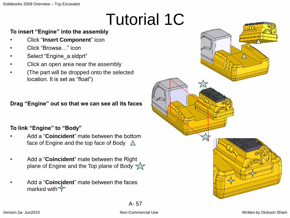
Tutorial 1CTo insert “Engine” into the assembly
• Click “Insert Component” icon
• Click “Browse…” icon
• Select “Engine_a.sldprt”
• Click an open area near the assembly
• (The part will be dropped onto the selected
location. It is set as “float”)
Drag “Engine” out so that we can see all its faces
To link “Engine” to “Body”
• Add a “Coincident” mate between the bottom
face of Engine and the top face of Body
• Add a “Coincident” mate between the Right
plane of Engine and the Top plane of Body
• Add a “Coincident” mate between the faces
marked with

Solidworks 2009 Overview – Toy Excavator
Non-Commercial UseVersion 2a- Jun2010 Written by Dickson Sham
A- 58
Tutorial 1CInsert “Arm_support” into the assembly
Drag “Arm_support” out so that we can
see all its faces
To link “Arm_support” to “Body”
• Coincident (Face to Face)
• Coincident (Face to Face)
• Coincident (Edge to Edge)
• Remark: We cannot add “Coincident
relation” between the faces with
because they are not parallel. Therefore
they can only add a constraint between
their edges

Solidworks 2009 Overview – Toy Excavator
Non-Commercial UseVersion 2a- Jun2010 Written by Dickson Sham
A- 59
Tutorial 1CInsert “Exhaust” into the assembly
Drag “Exhaust” out so that we can
see all its faces
Link “Exhaust” to “Body”
• Add a “Concentric” mate between the two
circular faces (Their axes are then
coincided)
• Add a “Coincident” mate (Face to face) as
shown.
• The angular orientation is not important in
this case, but you may rotate the part by
dragging directly Drag to
rotate
Solidworks 2009 Overview – Toy Excavator
Non-Commercial UseVersion 2a- Jun2010 Written by Dickson Sham
A- 60
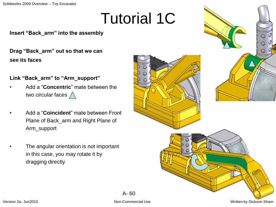
Tutorial 1CInsert “Back_arm” into the assembly
Drag “Back_arm” out so that we can
see its faces
Link “Back_arm” to “Arm_support”
• Add a “Concentric” mate between the
two circular faces
• Add a “Coincident” mate between Front
Plane of Back_arm and Right Plane of
Arm_support
• The angular orientation is not important
in this case, you may rotate it by
dragging directly

Solidworks 2009 Overview – Toy Excavator
Non-Commercial UseVersion 2a- Jun2010 Written by Dickson Sham
A- 61
Tutorial 1CInsert “Front_arm” into the assembly
Drag “Front_arm” out to see its faces
Link “Front_arm” to “Back_arm”
• Add a “Concentric” mate between the
two circular faces
• Add a “Coincident” mate between Front
Plane of front_arm and Front Plane of
back_arm
• The angular orientation is not important
in this case, you may rotate it by
dragging directly
Not For Commercial Use

Solidworks 2009 Overview – Toy Excavator
Non-Commercial UseVersion 2a- Jun2010 Written by Dickson Sham
A- 62
Tutorial 1CInsert “Bucket” into the assembly
Drag “Bucket” out to see its faces
Link “Bucket” to “Front_arm”
• Add a “Concentric” mate between the
two circular faces
• Add a “Coincident” mate between
Right Plane of bucket and Front Plane
of front_arm
• The angular orientation is not important
in this case, you may rotate it by
dragging directly or moving with triad
Snap the triad onto the axis and then
rotate the bucket along the axis

Solidworks 2009 Overview – Toy Excavator
Non-Commercial UseVersion 2a- Jun2010 Written by Dickson Sham
A- 63
Tutorial 1CTo simulate the motion of the machine arm:-
• Because the angular orientation at the joints
is not constrained, we can change the angular
positions of the arm and the bucket by
dragging directly
• Or dragging with triad (right-click on a part,
then select “move with triad”)
• (Remark: To snap the origin of the triad onto
the axis of rotation, right-click on the yellow
ball of the triad then select “move to
selection…”, then click on the circular face)
• (Remark: To rotate the front arm with triad, we
need to multi-select “front_arm” and “bucket”
first)
Triad
Front_arm &
Bucket (pre-
selected before
rotating)
Yellow
ball
Right-click on the
circle, then
deselect “snap
while dragging”

Solidworks 2009 Overview – Toy Excavator
Non-Commercial UseVersion 2a- Jun2010 Written by Dickson Sham
A- 64
Tutorial 1CFrom the assembly tree, we should have:
(f) Body fixed in position
Cabinet fully constrained
Engine fully constrained
Arm_support fully constrained
(-) Exhaust not fully constrained
(-) Back_arm not fully constrained
(-) Front_arm not fully constrained
(-) Bucket not fully constrained
To save the file:-
• Select “File/Save all” on the menu bar
• Click Yes on the popup window
• Click “Save As…” icon
• Enter “Upper_assm_a.sldasm” as filename
and save it in your project folder.
• Close All files.

Solidworks 2009 Overview – Toy Excavator
Non-Commercial UseVersion 2a- Jun2010 Written by Dickson Sham
A- 65
Tutorial 1C
To assemble the upper assembly to the base:-
• Select “File/New…” on the menu
• Click “Assembly” and then OK
• Click “Browse…”
• Select the file “Base_a.sldprt”
• Click “Open”
• Click ok to complete
• Click “Insert Component…” icon
• Click “Browse…”
• Change Files of Type to “Assembly (*.asm,
*.sldasm)”
• Select the file “upper_assm_a.sldasm” in your
folder
• Click on an open area near the Base (so that
the upper assembly can be free-to-move after
inserted)
Base (Fixed)
Upper_assm
(Free to move)

Solidworks 2009 Overview – Toy Excavator
Non-Commercial UseVersion 2a- Jun2010 Written by Dickson Sham
A- 66
Tutorial 1CLink “Upper_assm” to “Base”
• Add a “Concentric” mate between the two
circular faces
• Add a “Coincident” mate between the faces
with
To simulate the angular motion of the upper
assembly by dragging ANY component of
the upper assembly
Remark: the relative positions of
the components of the upper
assembly will not be changed
Solidworks 2009 Overview – Toy Excavator
Non-Commercial UseVersion 2a- Jun2010 Written by Dickson Sham
A- 67
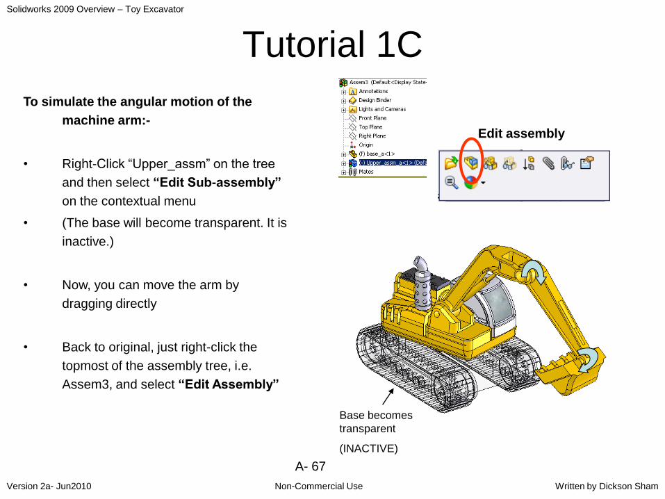
Tutorial 1C
To simulate the angular motion of the
machine arm:-
• Right-Click “Upper_assm” on the tree
and then select “Edit Sub-assembly”
on the contextual menu
• (The base will become transparent. It is
inactive.)
• Now, you can move the arm by
dragging directly
• Back to original, just right-click the
topmost of the assembly tree, i.e.
Assem3, and select “Edit Assembly”
Base becomes
transparent
(INACTIVE)
Edit assembly
Solidworks 2009 Overview – Toy Excavator
Non-Commercial UseVersion 2a- Jun2010 Written by Dickson Sham
A- 68
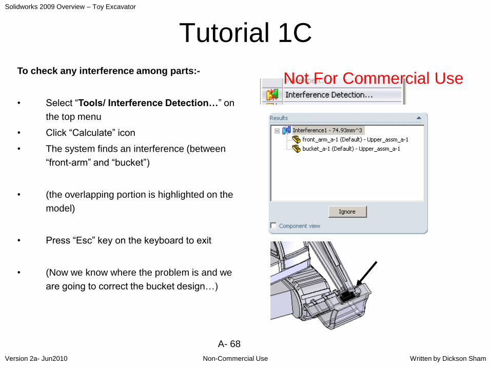
Tutorial 1C
To check any interference among parts:-
• Select “Tools/ Interference Detection…” on
the top menu
• Click “Calculate” icon
• The system finds an interference (between
“front-arm” and “bucket”)
• (the overlapping portion is highlighted on the
model)
• Press “Esc” key on the keyboard to exit
• (Now we know where the problem is and we
are going to correct the bucket design…)
Not For Commercial Use
Solidworks 2009 Overview – Toy Excavator
Non-Commercial UseVersion 2a- Jun2010 Written by Dickson Sham
A- 69
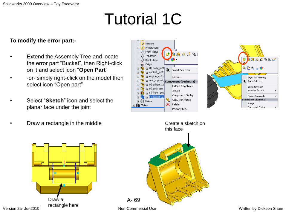
Tutorial 1CTo modify the error part:-
• Extend the Assembly Tree and locate
the error part “Bucket”, then Right-click
on it and select icon “Open Part”
• -or- simply right-click on the model then
select icon “Open part”
• Select “Sketch” icon and select the
planar face under the joint
• Draw a rectangle in the middle Create a sketch on
this face
Draw a
rectangle here
Solidworks 2009 Overview – Toy Excavator
Non-Commercial UseVersion 2a- Jun2010 Written by Dickson Sham
A- 70
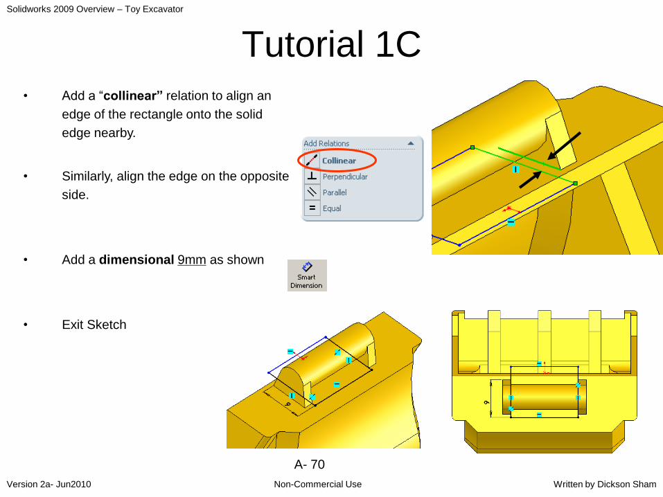
Tutorial 1C
• Add a “collinear” relation to align an
edge of the rectangle onto the solid
edge nearby.
• Similarly, align the edge on the opposite
side.
• Add a dimensional 9mm as shown
• Exit Sketch

Solidworks 2009 Overview – Toy Excavator
Non-Commercial UseVersion 2a- Jun2010 Written by Dickson Sham
A- 71
Tutorial 1C• Click “Extruded Cut” icon
• Enter 5mm as D1
• Click ok to complete
To re-do the interference check of the
whole assembly:-
• Select “ Window/Assem3” on the menu
bar to switch the display back to the
whole assembly.
• Click yes to rebuild
• You can see that the “Bucket” of the
assembly has been updated with an
opening
The bucket has
been updated
A hole is
made
Solidworks 2009 Overview – Toy Excavator
Non-Commercial UseVersion 2a- Jun2010 Written by Dickson Sham
A- 72
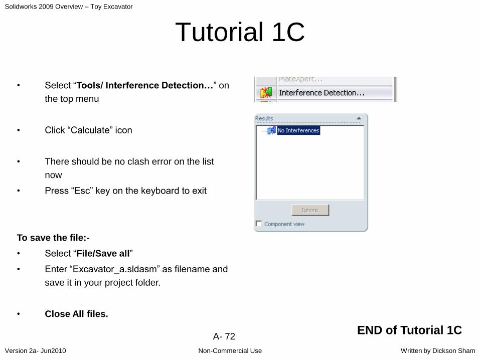
Tutorial 1C
• Select “Tools/ Interference Detection…” on
the top menu
• Click “Calculate” icon
• There should be no clash error on the list
now
• Press “Esc” key on the keyboard to exit
To save the file:-
• Select “File/Save all”
• Enter “Excavator_a.sldasm” as filename and
save it in your project folder.
• Close All files.
END of Tutorial 1C

Solidworks 2009 Overview – Toy Excavator
Non-Commercial UseVersion 2a- Jun2010 Written by Dickson Sham
A- 73
Summary of Tut-1CAssemble parts:-
Build an
upper
assembly
Put the upper
assembly
onto the base
Find a clash
between
parts
Modify the
error part
Redo the
clash
analysis
Insert
existing
components

Solidworks 2009 Overview – Toy Excavator
Non-Commercial UseVersion 2a- Jun2010 Written by Dickson Sham
A- 74
For enquiries, please contact:
Dickson S.W. ShamDepartment of Mechanical Engineering
Hong Kong Polytechnic University
Email : [email protected]
Office : R803
Tel : (852) 3400 2613
Website : http://myweb.polyu.edu.hk/~mmdsham