tutorial poser
TRANSCRIPT
Tutorial Manualfor Windows and Mac OS X®
TRADEMARK & COPYRIGHT NOTICEProgram copyright 1991-2006 e frontier America, Inc. and e frontier, Inc. All rights reserved. Interface copyright 1994-1999 Metacreations Corporation and 2000-2006 e frontier America, Inc. All rights reserved. e frontier is a trademark and Poser is a registered trademark of e frontier America, Inc. and e frontier, Inc. All other trademarks or registered trademarks are the properties of their respective owners. Technology and/or code contributed by the corporate contributors listed above is owned and copyrighted by the corporate contributors.
“Macintosh” is a registered trademark of Apple Computer, Inc. “Windows” is a registered trademark of Microsoft Corporation. “Pentium” is a registered trademark of Intel Corporation. All other product names mentioned in the manual and other documentation are used for identification purposes only and may be trademarks or registered trademarks of their respective companies. Registered and unregistered trademarks used herein are the exclusive property of their respective owners. e frontier America, Inc. makes no claim to any such marks, nor willingly or knowingly misused or misapplied such marks.
This manual as well as the software described herein is furnished under license and may only be used or copied in accordance with the terms of such license. Program copyright 1991-2006 by e frontier America, Inc. and e frontier, Inc., including the look and feel of the product. e frontier Poser 7 Tutorial Manual copyright 2006 by e frontier America, Inc. and e frontier, Inc. No part of this document may be reproduced in any form or by any means without prior written permission of e frontier America, Inc.
Before using this software or reading this document, make sure you have read, understood, and agreed to the license contained in the Poser 7 End User License Agreement (EULA) in the Poser 7 Reference Manual. Licensed product.
CONTENTS
PART 1 3D BASICS
CHAPTER 1: 3D BASICS 2About 3D Space . . . . . . . . . . . . . . . . . . . . . . . . . . . . . . . . . . . . . 2
Cartesian Coordinates . . . . . . . . . . . . . . . . . . . . . . . . . . . . . . 5Planes . . . . . . . . . . . . . . . . . . . . . . . . . . . . . . . . . . . . . . . . . . . 6Global vs. Local Coordinates . . . . . . . . . . . . . . . . . . . . . . . . . 6Transformation . . . . . . . . . . . . . . . . . . . . . . . . . . . . . . . . . . . . 8
CHAPTER 2: BASIC 3D ELEMENTS 10Vertices. . . . . . . . . . . . . . . . . . . . . . . . . . . . . . . . . . . . . . . . . . . 10Splines . . . . . . . . . . . . . . . . . . . . . . . . . . . . . . . . . . . . . . . . . . . 10Polygons. . . . . . . . . . . . . . . . . . . . . . . . . . . . . . . . . . . . . . . . . . 11
CHAPTER 3: MORE 3D ELEMENTS 12The Poser Figure Artist Workspace . . . . . . . . . . . . . . . . . . . . . 12Normals . . . . . . . . . . . . . . . . . . . . . . . . . . . . . . . . . . . . . . . . . . 12Camera. . . . . . . . . . . . . . . . . . . . . . . . . . . . . . . . . . . . . . . . . . . 12Lights . . . . . . . . . . . . . . . . . . . . . . . . . . . . . . . . . . . . . . . . . . . . 13Hierarchy . . . . . . . . . . . . . . . . . . . . . . . . . . . . . . . . . . . . . . . . . 13Animation . . . . . . . . . . . . . . . . . . . . . . . . . . . . . . . . . . . . . . . . . 13
Keyframing . . . . . . . . . . . . . . . . . . . . . . . . . . . . . . . . . . . . . . 13
CHAPTER 4: GROUPS 15Hair Groups . . . . . . . . . . . . . . . . . . . . . . . . . . . . . . . . . . . . . . . 17Cloth Groups. . . . . . . . . . . . . . . . . . . . . . . . . . . . . . . . . . . . . . . 17
CHAPTER 5: MULTI /SUB-OBJECT MATERIALS 19Why Multi/Sub-object Materials? . . . . . . . . . . . . . . . . . . . . . . . 19Color . . . . . . . . . . . . . . . . . . . . . . . . . . . . . . . . . . . . . . . . . . . . . 20About Maps & Templates . . . . . . . . . . . . . . . . . . . . . . . . . . . . . 20Bump Maps. . . . . . . . . . . . . . . . . . . . . . . . . . . . . . . . . . . . . . . . 21Transparency Maps . . . . . . . . . . . . . . . . . . . . . . . . . . . . . . . . . 22Reflection Map . . . . . . . . . . . . . . . . . . . . . . . . . . . . . . . . . . . . . 23Displacement Map . . . . . . . . . . . . . . . . . . . . . . . . . . . . . . . . . . 23Texture Map . . . . . . . . . . . . . . . . . . . . . . . . . . . . . . . . . . . . . . . 23Procedural Shaders . . . . . . . . . . . . . . . . . . . . . . . . . . . . . . . . . 25Putting It All Together . . . . . . . . . . . . . . . . . . . . . . . . . . . . . . . . 25
PART 2 BASIC POSER 7 OPERATIONS
CHAPTER 6: POSER 7 OPERATIONS TUTORIAL 27The Basics . . . . . . . . . . . . . . . . . . . . . . . . . . . . . . . . . . . . . . . . 27
Lesson 1: Working with Cameras . . . . . . . . . . . . . . . . . . . . . 27Lesson 2: Tracking Modes . . . . . . . . . . . . . . . . . . . . . . . . . . 33
Working with Lights. . . . . . . . . . . . . . . . . . . . . . . . . . . . . . . . . . 34Lesson 1: Using the Light Controls . . . . . . . . . . . . . . . . . . . . 34
Using Poser 7’s Tools. . . . . . . . . . . . . . . . . . . . . . . . . . . . . . . . 37Lesson 1: The Parameter Dials . . . . . . . . . . . . . . . . . . . . . . 37Lesson 2: The Rotate Tool . . . . . . . . . . . . . . . . . . . . . . . . . . 39Lesson 3: The Twist Tool . . . . . . . . . . . . . . . . . . . . . . . . . . . 42Lesson 4: The Translate Tools . . . . . . . . . . . . . . . . . . . . . . . 44
Poser 7 Tutorial Manual
Posing. . . . . . . . . . . . . . . . . . . . . . . . . . . . . . . . . . . . . . . . . . . . 48Lesson 1: Creating Poses . . . . . . . . . . . . . . . . . . . . . . . . . . . 48Lesson 2: Adding Poses to the Poses Library . . . . . . . . . . . 54Lesson 3: Posing Faces . . . . . . . . . . . . . . . . . . . . . . . . . . . . 56
Rendering . . . . . . . . . . . . . . . . . . . . . . . . . . . . . . . . . . . . . . . . . 59Advanced Tutorials . . . . . . . . . . . . . . . . . . . . . . . . . . . . . . . . . . 64Character Creation and Animation . . . . . . . . . . . . . . . . . . . . . . 65
Lesson 1: Creating a Clown from Scratch. . . . . . . . . . . . . . . 65Lesson 2: Making the Clown Walk . . . . . . . . . . . . . . . . . . . . 70Lesson 3: The Walk Designer . . . . . . . . . . . . . . . . . . . . . . . . 78Lesson 4: Keyframe Editing . . . . . . . . . . . . . . . . . . . . . . . . . 85Lesson 5: Adding the Final Touch. . . . . . . . . . . . . . . . . . . . . 93Lesson 6: Setting Animated Cameras and Test Rendering . 95Lesson 7: Final Render . . . . . . . . . . . . . . . . . . . . . . . . . . . . . 97
CHAPTER 7: CONTENT MANAGEMENT 98The Library Palette . . . . . . . . . . . . . . . . . . . . . . . . . . . . . . . . . . 98
Adding New Content . . . . . . . . . . . . . . . . . . . . . . . . . . . . . . . 98Adding New Runtimes. . . . . . . . . . . . . . . . . . . . . . . . . . . . . . 99
Content Paradise . . . . . . . . . . . . . . . . . . . . . . . . . . . . . . . . . . . 99Content Collections. . . . . . . . . . . . . . . . . . . . . . . . . . . . . . . . . 100
CHAPTER 8: FIREFLY RENDER TIPS 103Automatic vs. Manual Settings . . . . . . . . . . . . . . . . . . . . . . . . 103Scene Settings and Specifics . . . . . . . . . . . . . . . . . . . . . . . . . 104
CHAPTER 9: CREATING AND ASSIGNING TEXTURES 109Creating Texture Templates . . . . . . . . . . . . . . . . . . . . . . . . . . 109Creating and Using Texture Maps . . . . . . . . . . . . . . . . . . . . . 110
The Head Map . . . . . . . . . . . . . . . . . . . . . . . . . . . . . . . . . . 112The Body Map. . . . . . . . . . . . . . . . . . . . . . . . . . . . . . . . . . . 113
Creating and Using Bump, Reflection, and Transparency Maps . . . . . . . . . . . . . . . . . . . . . . . . . . . . . . . . 114
PART 3 ADDING REALISM
CHAPTER 10: THE FACE ROOM 117Getting Ready for Your Face Room Project . . . . . . . . . . . . . . 119Choosing and Preparing Photos . . . . . . . . . . . . . . . . . . . . . . . 120
Important Notes about Photo Size . . . . . . . . . . . . . . . . . . . 121Improving Photos with an Image Editor . . . . . . . . . . . . . . . 122Adding Symmetry to the Front Photo . . . . . . . . . . . . . . . . . 125
Task 1: Import the Photos to the Face Room . . . . . . . . . . . . . 128Importing the Front Photo . . . . . . . . . . . . . . . . . . . . . . . . . . 129Importing the Side Photo. . . . . . . . . . . . . . . . . . . . . . . . . . . 132
Task 2: Moving, Scaling, or Rotating the Head Guides . . . . . 135Adjusting Front Scaling and Position . . . . . . . . . . . . . . . . . 136Adjusting Side Scaling and Position . . . . . . . . . . . . . . . . . . 137Compensating for Head Tilt or Rotation . . . . . . . . . . . . . . . 138
Task 3: Fine-Tuning the Texture. . . . . . . . . . . . . . . . . . . . . . . 140Refining the Front View. . . . . . . . . . . . . . . . . . . . . . . . . . . . 141
CONTENTS
Refining the Side View . . . . . . . . . . . . . . . . . . . . . . . . . . . . 145Adding Texture Variation . . . . . . . . . . . . . . . . . . . . . . . . . . 150Saving Your Texture . . . . . . . . . . . . . . . . . . . . . . . . . . . . . . 151
Task 4: Refine the Head Shape . . . . . . . . . . . . . . . . . . . . . . . 152Creating a Random Face . . . . . . . . . . . . . . . . . . . . . . . . . . 153Changing the Face Shape Interactively . . . . . . . . . . . . . . . 156Changing the Face with Morph Dials . . . . . . . . . . . . . . . . . 157
Task 5: Completing Your Character . . . . . . . . . . . . . . . . . . . . 159Creating a Permanent Character . . . . . . . . . . . . . . . . . . . . 160Using Third-Party Textures with the Face Room . . . . . . . . 163Creating a Morphable Face . . . . . . . . . . . . . . . . . . . . . . . . 164
CHAPTER 11: THE CLOTH ROOM 167Task 1: Creating Still Images with Dynamic Clothing . . . . . . . 168Task 2: Controlling How Clothing Acts . . . . . . . . . . . . . . . . . . 176Task 3: Using Different Materials in Clothing (Part 1). . . . . . . 183Task 4: Using Different Materials in Clothing (Part 2). . . . . . . 189Task 5: Saving Dynamic Clothing to a Library . . . . . . . . . . . . 193Task 6: Adding Wind to Your Project . . . . . . . . . . . . . . . . . . . 194Adjusting Dynamic Clothing to Fit Other Characters . . . . . . . 199
Fitting a Heavier Body Shape . . . . . . . . . . . . . . . . . . . . . . . 199Fitting a Lighter Body Shape. . . . . . . . . . . . . . . . . . . . . . . . 202
CHAPTER 12: THE HAIR ROOM 206Task 1: Quick Start to Creating and Styling Hair . . . . . . . . . . 209
Adding Groups . . . . . . . . . . . . . . . . . . . . . . . . . . . . . . . . . . 209Growing the Hair . . . . . . . . . . . . . . . . . . . . . . . . . . . . . . . . . 211Adding or Removing Curliness . . . . . . . . . . . . . . . . . . . . . . 215Styling the Hair . . . . . . . . . . . . . . . . . . . . . . . . . . . . . . . . . . 218
Creating Multi-Grouped Hair. . . . . . . . . . . . . . . . . . . . . . . . . . 228Using a Modeling or UV Mapping Program . . . . . . . . . . . . 231Using Poser 7's Group Editor . . . . . . . . . . . . . . . . . . . . . . . 236
Task 2: Growing and Styling Multi-Grouped Hair . . . . . . . . . . 243Saving Your Hair to the Library. . . . . . . . . . . . . . . . . . . . . . . . 255Setting Hair Dynamics . . . . . . . . . . . . . . . . . . . . . . . . . . . . . . 257Creating and Changing the Hair Color . . . . . . . . . . . . . . . . . . 260
Hair Coloring Tip! . . . . . . . . . . . . . . . . . . . . . . . . . . . . . . . . 265
CHAPTER 13: BUILDING A BASIC SKIN SHADER 267Note on Workflow . . . . . . . . . . . . . . . . . . . . . . . . . . . . . . . . . . 267Advanced Materials . . . . . . . . . . . . . . . . . . . . . . . . . . . . . . . . 267Getting Started . . . . . . . . . . . . . . . . . . . . . . . . . . . . . . . . . . . . 267
Bump Mapping . . . . . . . . . . . . . . . . . . . . . . . . . . . . . . . . . . 268Specularity . . . . . . . . . . . . . . . . . . . . . . . . . . . . . . . . . . . . . 269Diffuse Skin Shader . . . . . . . . . . . . . . . . . . . . . . . . . . . . . . 270
Some Notes on Eyes . . . . . . . . . . . . . . . . . . . . . . . . . . . . . . . 272Conclusion . . . . . . . . . . . . . . . . . . . . . . . . . . . . . . . . . . . . . . . 274
CHAPTER 14: IMAGE BASED LIGHTING 276
PART 4 POSING AND ANIMATION

Poser 7 Tutorial Manual
CHAPTER 15: USING TALK DESIGNER 284
CHAPTER 16: ANIMATION LAYERS 288
CHAPTER 17: ADVANCED POSING AND ANIMATION 297Auto Balance and Posing . . . . . . . . . . . . . . . . . . . . . . . . . . . . 297Motion Capture and Animations . . . . . . . . . . . . . . . . . . . . . . . 298
Importing and Exporting Motion Capture Files . . . . . . . . . . 299
PART 5 FIGURE SHAPING AND CREATION
CHAPTER 18: MORPH TARGET CREATION 301
CHAPTER 19: ADVANCED BODY SHAPING 307Morph Targets. . . . . . . . . . . . . . . . . . . . . . . . . . . . . . . . . . . . . 307
Setting Up Morph Targets . . . . . . . . . . . . . . . . . . . . . . . . . . 308Morph Target Tutorial . . . . . . . . . . . . . . . . . . . . . . . . . . . . . . . 309Figure Joints and Blend Zones . . . . . . . . . . . . . . . . . . . . . . . . 314
Editing Joint Parameters . . . . . . . . . . . . . . . . . . . . . . . . . . . 315Using the Joint Editor . . . . . . . . . . . . . . . . . . . . . . . . . . . . . 317Interactively Editing Joint Parameters. . . . . . . . . . . . . . . . . 317Joint Attributes. . . . . . . . . . . . . . . . . . . . . . . . . . . . . . . . . . . 319Spherical Falloff Zones . . . . . . . . . . . . . . . . . . . . . . . . . . . . 329
CHAPTER 20: BASIC FIGURE CREATION 331Example One: Wormy. . . . . . . . . . . . . . . . . . . . . . . . . . . . . . . 331Example Two: Goldy the Robot . . . . . . . . . . . . . . . . . . . . . . . 332
CHAPTER 21: ADVANCED FIGURE CREATION 335Creating Figure Models. . . . . . . . . . . . . . . . . . . . . . . . . . . . . . 336
Model Format . . . . . . . . . . . . . . . . . . . . . . . . . . . . . . . . . . . 336Grouping . . . . . . . . . . . . . . . . . . . . . . . . . . . . . . . . . . . . . . . 336
Creating Hierarchy Files . . . . . . . . . . . . . . . . . . . . . . . . . . . . . 339Hierarchy File Explained . . . . . . . . . . . . . . . . . . . . . . . . . . . 340Converting Hierarchy Files . . . . . . . . . . . . . . . . . . . . . . . . . 344Verifying Hierarchy Files . . . . . . . . . . . . . . . . . . . . . . . . . . . 344
. . . . . . . . . . . . . . . . . . . . . . . . . . . . . . . . . . . . . . . . . . . . . . . . 344Setting Up a Standard Figure . . . . . . . . . . . . . . . . . . . . . . . . . 345
Applying the Standard Hierarchy . . . . . . . . . . . . . . . . . . . . 345Applying the Standard Rotation Order . . . . . . . . . . . . . . . . 345
Adjusting Joint Parameters . . . . . . . . . . . . . . . . . . . . . . . . . . . 345Setting Limits . . . . . . . . . . . . . . . . . . . . . . . . . . . . . . . . . . . . . 346Setting Favored IK Angles . . . . . . . . . . . . . . . . . . . . . . . . . . . 347Memorizing Default Positions . . . . . . . . . . . . . . . . . . . . . . . . . 347Setting Surface Materials . . . . . . . . . . . . . . . . . . . . . . . . . . . . 348Adding Morph Targets . . . . . . . . . . . . . . . . . . . . . . . . . . . . . . 348Setting Body Part Names . . . . . . . . . . . . . . . . . . . . . . . . . . . . 348Saving new figures to the library. . . . . . . . . . . . . . . . . . . . . . . 348Tutorial - Poser Figure Creation . . . . . . . . . . . . . . . . . . . . . . . 348
PART 1
3D Basics
2
POSER 7 TUTORIAL MANUAL
Chapter 1: 3D Basicshis part describes basic 3D concepts. The following discussion centers on Poser Figure Artist, however most of these concepts apply to all 3D applications. Novice 3D artists should read the entire chapter to gain valuable “behind the
scenes” insight that will help in learning and using Poser Figure Artist. Veteran 3D users can use this chapter as a handy reference or refresher.
ABOUT 3D SPACE
Let’s begin by defining the three dimensions:
Zero dimension: A point is an example of a zero-dimensional object. It defines a point in space but has no length, height, or width.
First dimension: A one-dimensional object is a single line. It has length but no height or depth.
Second dimension: A two-dimensional object has any two of the following three dimensions:
LengthHeightDepth
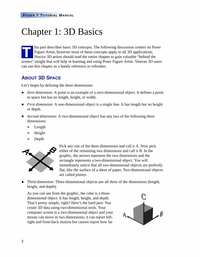
Pick any one of the three dimensions and call it A. Now pick either of the remaining two dimensions and call it B. In the graphic, the arrows represent the two dimensions and the rectangle represents a two-dimensional object. You will immediately notice that all two-dimensional objects are perfectly flat, like the surface of a sheet of paper. Two-dimensional objects are called planes.
Third dimension: Three-dimensional objects use all three of the dimensions (length, height, and depth).
As you can see from the graphic, the cube is a three-dimensional object. It has length, height, and depth. That’s pretty simple, right? Here’s the hard part: You create 3D data using two-dimensional tools. Your computer screen is a two-dimensional object and your mouse can move in two dimensions; it can report left-right and front-back motion but cannot report how far
T
3
3D BASICS
above or below the desk it is. Furthermore, your output will always be two-dimensional. Look at the above graphic: It does not have depth. It does, however, represent three dimensions using a simple optical illusion called perspective, which is defined as the tendency of objects to appear progressively smaller the farther away they are until they disappear on the horizon at a location called the vanishing point. You can see this by standing at the corner of a long building and noticing how the roofline appears to get closer to the ground the farther away you look. Given these limitations, you ask, how can one create 3D information?
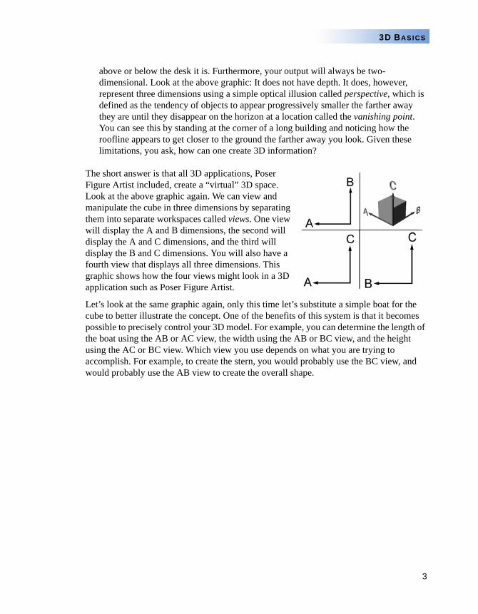
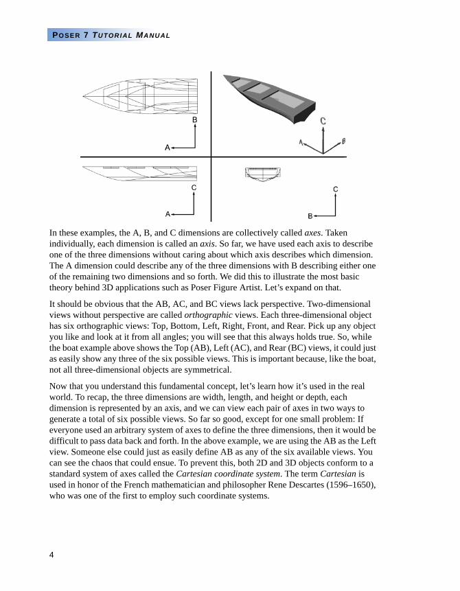
The short answer is that all 3D applications, Poser Figure Artist included, create a “virtual” 3D space. Look at the above graphic again. We can view and manipulate the cube in three dimensions by separating them into separate workspaces called views. One view will display the A and B dimensions, the second will display the A and C dimensions, and the third will display the B and C dimensions. You will also have a fourth view that displays all three dimensions. This graphic shows how the four views might look in a 3D application such as Poser Figure Artist.
Let’s look at the same graphic again, only this time let’s substitute a simple boat for the cube to better illustrate the concept. One of the benefits of this system is that it becomes possible to precisely control your 3D model. For example, you can determine the length of the boat using the AB or AC view, the width using the AB or BC view, and the height using the AC or BC view. Which view you use depends on what you are trying to accomplish. For example, to create the stern, you would probably use the BC view, and would probably use the AB view to create the overall shape.
4
POSER 7 TUTORIAL MANUAL
In these examples, the A, B, and C dimensions are collectively called axes. Taken individually, each dimension is called an axis. So far, we have used each axis to describe one of the three dimensions without caring about which axis describes which dimension. The A dimension could describe any of the three dimensions with B describing either one of the remaining two dimensions and so forth. We did this to illustrate the most basic theory behind 3D applications such as Poser Figure Artist. Let’s expand on that.
It should be obvious that the AB, AC, and BC views lack perspective. Two-dimensional views without perspective are called orthographic views. Each three-dimensional object has six orthographic views: Top, Bottom, Left, Right, Front, and Rear. Pick up any object you like and look at it from all angles; you will see that this always holds true. So, while the boat example above shows the Top (AB), Left (AC), and Rear (BC) views, it could just as easily show any three of the six possible views. This is important because, like the boat, not all three-dimensional objects are symmetrical.
Now that you understand this fundamental concept, let’s learn how it’s used in the real world. To recap, the three dimensions are width, length, and height or depth, each dimension is represented by an axis, and we can view each pair of axes in two ways to generate a total of six possible views. So far so good, except for one small problem: If everyone used an arbitrary system of axes to define the three dimensions, then it would be difficult to pass data back and forth. In the above example, we are using the AB as the Left view. Someone else could just as easily define AB as any of the six available views. You can see the chaos that could ensue. To prevent this, both 2D and 3D objects conform to a standard system of axes called the Cartesian coordinate system. The term Cartesian is used in honor of the French mathematician and philosopher Rene Descartes (1596–1650), who was one of the first to employ such coordinate systems.
5
3D BASICS
CARTESIAN COORDINATES
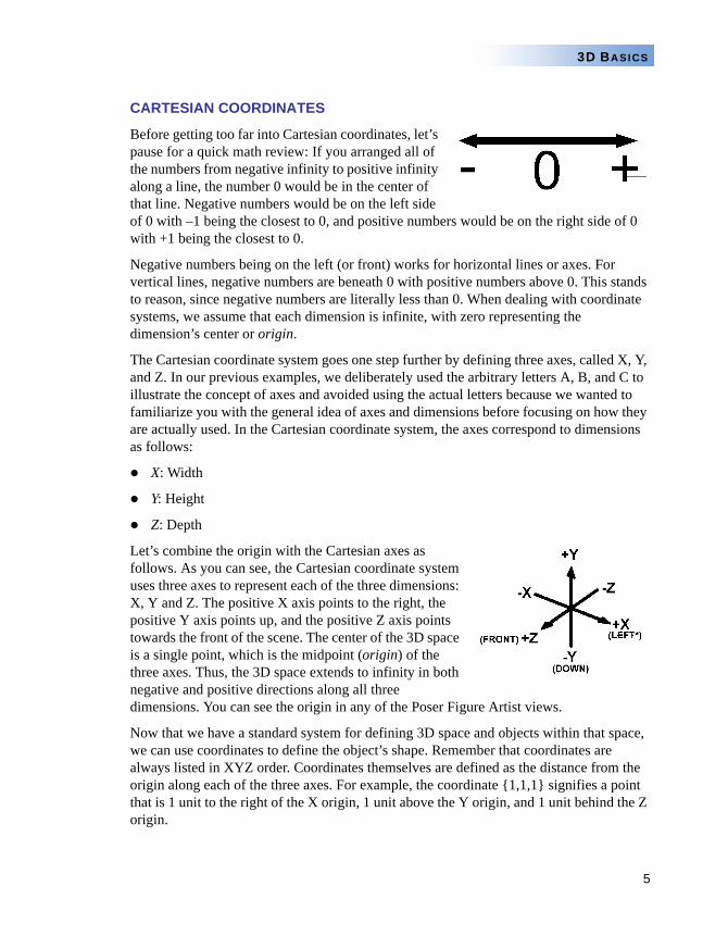
Before getting too far into Cartesian coordinates, let’s pause for a quick math review: If you arranged all of the numbers from negative infinity to positive infinity along a line, the number 0 would be in the center of that line. Negative numbers would be on the left side of 0 with –1 being the closest to 0, and positive numbers would be on the right side of 0 with +1 being the closest to 0.
Negative numbers being on the left (or front) works for horizontal lines or axes. For vertical lines, negative numbers are beneath 0 with positive numbers above 0. This stands to reason, since negative numbers are literally less than 0. When dealing with coordinate systems, we assume that each dimension is infinite, with zero representing the dimension’s center or origin.
The Cartesian coordinate system goes one step further by defining three axes, called X, Y, and Z. In our previous examples, we deliberately used the arbitrary letters A, B, and C to illustrate the concept of axes and avoided using the actual letters because we wanted to familiarize you with the general idea of axes and dimensions before focusing on how they are actually used. In the Cartesian coordinate system, the axes correspond to dimensions as follows:
X: Width
Y: Height
Z: Depth
Let’s combine the origin with the Cartesian axes as follows. As you can see, the Cartesian coordinate system uses three axes to represent each of the three dimensions: X, Y and Z. The positive X axis points to the right, the positive Y axis points up, and the positive Z axis points towards the front of the scene. The center of the 3D space is a single point, which is the midpoint (origin) of the three axes. Thus, the 3D space extends to infinity in both negative and positive directions along all three dimensions. You can see the origin in any of the Poser Figure Artist views.
Now that we have a standard system for defining 3D space and objects within that space, we can use coordinates to define the object’s shape. Remember that coordinates are always listed in XYZ order. Coordinates themselves are defined as the distance from the origin along each of the three axes. For example, the coordinate {1,1,1} signifies a point that is 1 unit to the right of the X origin, 1 unit above the Y origin, and 1 unit behind the Z origin.
6
POSER 7 TUTORIAL MANUAL
NOTE THE FORMAT OF LISTING THE X, Y, AND Z COORDINATES WITHIN BRACES AND SEPARATED BY COMMAS IS THE STANDARD SHORTHAND USED WITH THE CARTESIAN COORDINATE SYSTEM.
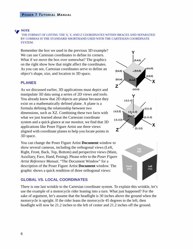
Remember the box we used in the previous 3D example? We can use Cartesian coordinates to define its corners. What if we move the box over somewhat? The graphics on the right show how that might affect the coordinates. As you can see, Cartesian coordinates serve to define an object’s shape, size, and location in 3D space.
PLANES
As we discussed earlier, 3D applications must depict and manipulate 3D data using a series of 2D views and tools. You already know that 2D objects are planar because they exist on a mathematically defined plane. A plane is a formula defining the relationship between two dimensions, such as XZ. Combining these two facts with what we just learned about the Cartesian coordinate system and a quick glance at our monitor, we find that 3D applications like Poser Figure Artist use three views aligned with coordinate planes to help you locate points in 3D space.
You can change the Poser Figure Artist Document window to show several cameras, including the orthogonal views (Left, Right, Front, Back, Top, Bottom) and perspective views (Main, Auxiliary, Face, Hand, Posing). Please refer to the Poser Figure Artist Reference Manual, “The Document Window” for a description of the Poser Figure Artist Document window. The graphic shows a quick rendition of three orthogonal views:
GLOBAL VS. LOCAL COORDINATES
There is one last wrinkle to the Cartesian coordinate system. To explain this wrinkle, let’s use the example of a motorcycle rider leaning into a turn. What just happened? For the sake of argument, let’s assume that the headlight is 30 inches above the ground when the motorcycle is upright. If the rider leans the motorcycle 45 degrees to the left, then headlight will now be 21.2 inches to the left of center and 21.2 inches off the ground.
7
3D BASICS
NOTEFOR ANYONE INTO TRIGONOMETRY, WE FIND THE NEW LOCATION BY MULTIPLYING THE ORIGINAL LOCATION BY THE SIN AND COSINE OF THE ANGLE. IN THIS CASE, SIN(45) = COS(45) =.707, AND.707*30= APPROX. 21.2.
Thus, the headlight’s coordinates will have changed from {0, 30,0} to {21.2, 0, 21.2}. However, nothing has changed about the motorcycle itself. The headlight is still in the exact same position relative to the rest of the machine. To demonstrate this, let’s create a second 3D space using the motorcycle’s center of gravity (balance point) as the origin. Let’s further say that the headlight is 12 inches above and 30 inches in front of the center of gravity. This means that the headlight’s relative coordinates are {0, 12, -30}, and these relative coordinates do not change because the headlight does not move relative to the center of gravity. But what do we mean by relative?
Has the motorcycle leaned 45 degrees to the left, or has the world leaned 45 degrees to the right? To an observer standing on the ground, the motorcycle has leaned over 45 degrees. To the rider, s/he is still on top of the motorcycle and it is the world that has leaned over 45 degrees. Further, the rider maintains her or his relationship to the motorcycle, meaning (for example) that her or his head is still 30 inches behind and 32 inches above the headlight. Thus, while the motorcycle’s world coordinates have changed, its object (or local) coordinates have remained the same.
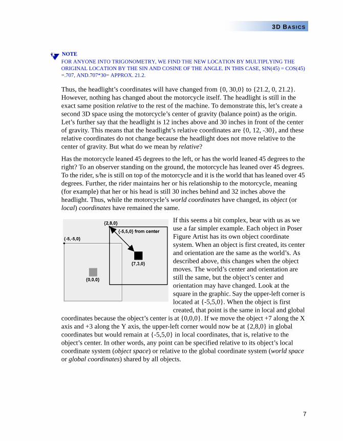
If this seems a bit complex, bear with us as we use a far simpler example. Each object in Poser Figure Artist has its own object coordinate system. When an object is first created, its center and orientation are the same as the world’s. As described above, this changes when the object moves. The world’s center and orientation are still the same, but the object’s center and orientation may have changed. Look at the square in the graphic. Say the upper-left corner is located at {-5,5,0}. When the object is first created, that point is the same in local and global
coordinates because the object’s center is at {0,0,0}. If we move the object +7 along the X axis and +3 along the Y axis, the upper-left corner would now be at {2,8,0} in global coordinates but would remain at {-5,5,0} in local coordinates, that is, relative to the object’s center. In other words, any point can be specified relative to its object’s local coordinate system (object space) or relative to the global coordinate system (world space or global coordinates) shared by all objects.
8
POSER 7 TUTORIAL MANUAL
TRANSFORMATION
So far, you have learned about 3D objects, the Cartesian coordinate system, and the difference between object space and world space. Let’s move on and learn how we can use XYZ values to define an object’s transformation in addition to its size, shape, and position.
An object’s transformation describes an object’s position (translation), orientation (rotation), and size (scale) in 3D space. When an object is first created, its transformation is set to align with the global coordinates. Its position is set to {0,0,0}, its orientation is set to {0,0,0}, and its size is set to {1,1,1}. An object’s transformation values are almost certain to change as you work with the object.
Translation
An object’s translation describes its position in 3D space relative to its center and is measured in defined grid units. Let’s take another look at the box we used in an earlier example:
As you can see, the box’s center is the same as the origin ({0,0,0}). What happens if you want to move the box? You can move each one of the points, delete the existing box and draw a new one in its new location, or simply translate the box. For example, setting a Translate value of {2,2,2} would move box’s lower left corner to {0,0,0} since (-2)+2=0. Again, the Translate value refers to the location of the center of the object relative to world space.
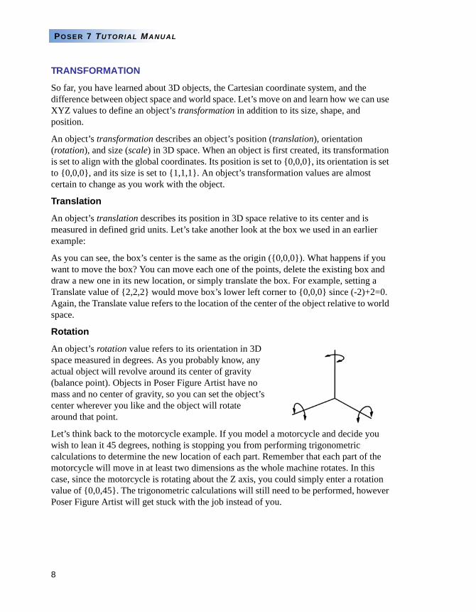
Rotation
An object’s rotation value refers to its orientation in 3D space measured in degrees. As you probably know, any actual object will revolve around its center of gravity (balance point). Objects in Poser Figure Artist have no mass and no center of gravity, so you can set the object’s center wherever you like and the object will rotate around that point.
Let’s think back to the motorcycle example. If you model a motorcycle and decide you wish to lean it 45 degrees, nothing is stopping you from performing trigonometric calculations to determine the new location of each part. Remember that each part of the motorcycle will move in at least two dimensions as the whole machine rotates. In this case, since the motorcycle is rotating about the Z axis, you could simply enter a rotation value of {0,0,45}. The trigonometric calculations will still need to be performed, however Poser Figure Artist will get stuck with the job instead of you.
9
3D BASICS
Scale
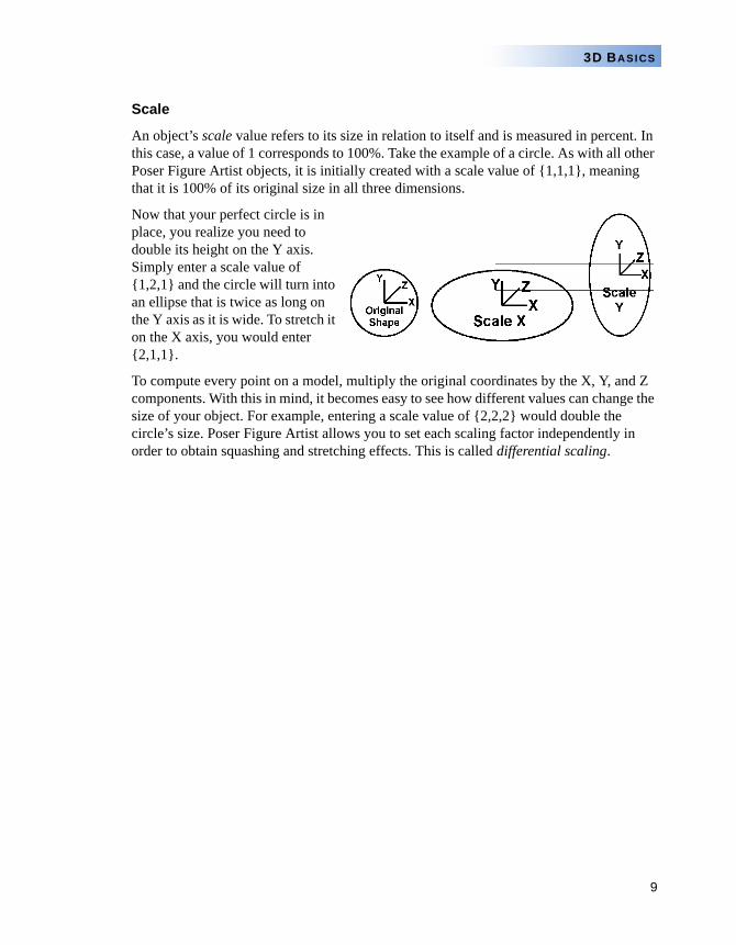
An object’s scale value refers to its size in relation to itself and is measured in percent. In this case, a value of 1 corresponds to 100%. Take the example of a circle. As with all other Poser Figure Artist objects, it is initially created with a scale value of {1,1,1}, meaning that it is 100% of its original size in all three dimensions.
Now that your perfect circle is in place, you realize you need to double its height on the Y axis. Simply enter a scale value of {1,2,1} and the circle will turn into an ellipse that is twice as long on the Y axis as it is wide. To stretch it on the X axis, you would enter {2,1,1}.
To compute every point on a model, multiply the original coordinates by the X, Y, and Z components. With this in mind, it becomes easy to see how different values can change the size of your object. For example, entering a scale value of {2,2,2} would double the circle’s size. Poser Figure Artist allows you to set each scaling factor independently in order to obtain squashing and stretching effects. This is called differential scaling.
10
POSER 7 TUTORIAL MANUAL
Chapter 2: Basic 3D Elementsow that you’ve learned about 3D objects, Cartesian coordinates, object space vs. world space, and object transformations, let’s go ahead and learn more about 3D objects themselves.
VERTICES
A point is a zero-dimensional (0D) object in 3D space. It has a set of coordinates to define its location but has no length, width, or height. It is nothing more than a location in Cartesian space. However, we can connect points to create edges or polylines. An edge is part of a polygon between two vertices, and a polyline connects two vertices together that are not part of a polygon. At its root, 3D modeling consists of nothing more than connecting a series of vertices together to create 3D objects.
A group of vertices used to define a 3D object is called a point cloud. Each point in a cloud is usually called a vertex and is used to define one of the corners of a polygon. Points used to define a spline (see below) are called control points. We’ll define these terms a little later.
SPLINES
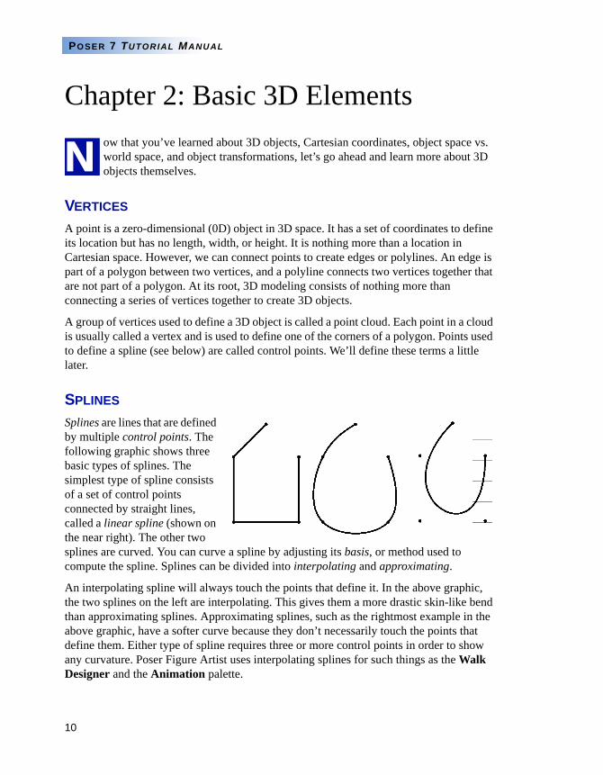
Splines are lines that are defined by multiple control points. The following graphic shows three basic types of splines. The simplest type of spline consists of a set of control points connected by straight lines, called a linear spline (shown on the near right). The other two splines are curved. You can curve a spline by adjusting its basis, or method used to compute the spline. Splines can be divided into interpolating and approximating.
An interpolating spline will always touch the points that define it. In the above graphic, the two splines on the left are interpolating. This gives them a more drastic skin-like bend than approximating splines. Approximating splines, such as the rightmost example in the above graphic, have a softer curve because they don’t necessarily touch the points that define them. Either type of spline requires three or more control points in order to show any curvature. Poser Figure Artist uses interpolating splines for such things as the Walk Designer and the Animation palette.
N
11
3D BASICS
POLYGONS
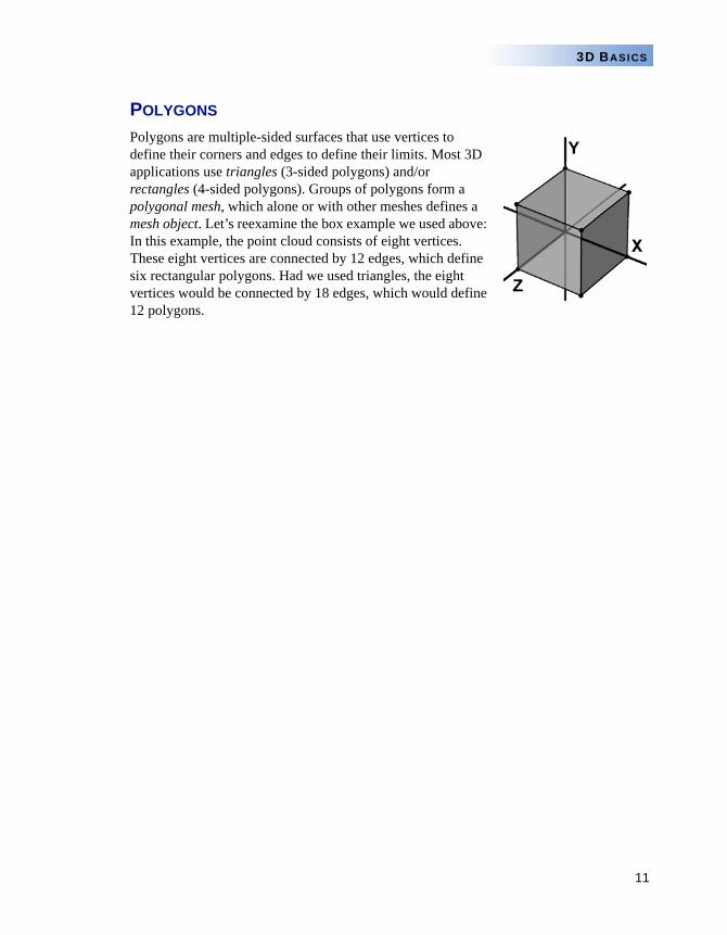
Polygons are multiple-sided surfaces that use vertices to define their corners and edges to define their limits. Most 3D applications use triangles (3-sided polygons) and/or rectangles (4-sided polygons). Groups of polygons form a polygonal mesh, which alone or with other meshes defines a mesh object. Let’s reexamine the box example we used above: In this example, the point cloud consists of eight vertices. These eight vertices are connected by 12 edges, which define six rectangular polygons. Had we used triangles, the eight vertices would be connected by 18 edges, which would define 12 polygons.
12
POSER 7 TUTORIAL MANUAL
Chapter 3: More 3D Elementse have just a few more basics to cover before diving into the actual tutorials.
THE POSER FIGURE ARTIST WORKSPACE
The Poser Figure Artist workspace (you’ll see this referred to throughout this manual) is the virtual 3D world in which you build your scenes. This world contains an origin and the three axes.
The Document window acts as the viewfinder for the currently selected camera. By look-ing through this viewfinder, you can see the workspace. Please refer to the Poser Figure Artist Reference Manual, “The Document Window” for more information about the Docu-ment window.
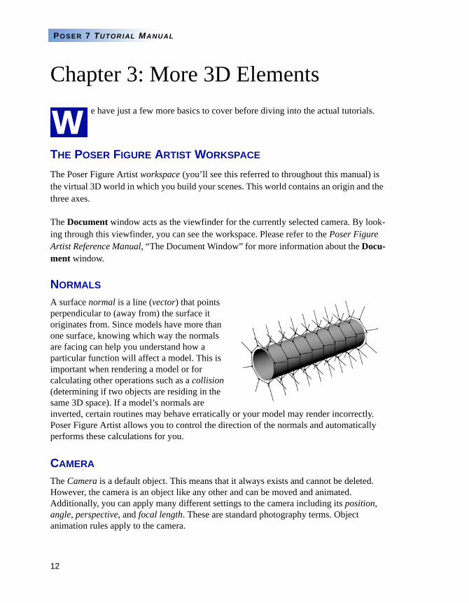
NORMALS
A surface normal is a line (vector) that points perpendicular to (away from) the surface it originates from. Since models have more than one surface, knowing which way the normals are facing can help you understand how a particular function will affect a model. This is important when rendering a model or for calculating other operations such as a collision (determining if two objects are residing in the same 3D space). If a model’s normals are inverted, certain routines may behave erratically or your model may render incorrectly. Poser Figure Artist allows you to control the direction of the normals and automatically performs these calculations for you.
CAMERA
The Camera is a default object. This means that it always exists and cannot be deleted. However, the camera is an object like any other and can be moved and animated. Additionally, you can apply many different settings to the camera including its position, angle, perspective, and focal length. These are standard photography terms. Object animation rules apply to the camera.
W
13
3D BASICS
LIGHTS
A light source is a special kind of primitive. When Poser Figure Artist launches, it places three default lights in your scene. You can add, edit and remove lights in your scene and can also control and animate many settings such as color, intensity, position, shaders (gels), etc.
HIERARCHY
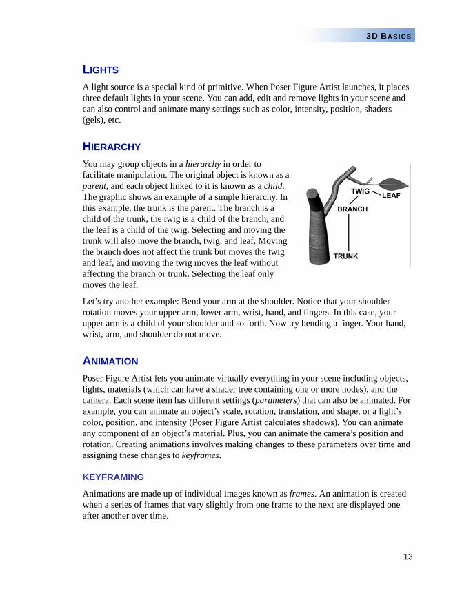
You may group objects in a hierarchy in order to facilitate manipulation. The original object is known as a parent, and each object linked to it is known as a child. The graphic shows an example of a simple hierarchy. In this example, the trunk is the parent. The branch is a child of the trunk, the twig is a child of the branch, and the leaf is a child of the twig. Selecting and moving the trunk will also move the branch, twig, and leaf. Moving the branch does not affect the trunk but moves the twig and leaf, and moving the twig moves the leaf without affecting the branch or trunk. Selecting the leaf only moves the leaf.
Let’s try another example: Bend your arm at the shoulder. Notice that your shoulder rotation moves your upper arm, lower arm, wrist, hand, and fingers. In this case, your upper arm is a child of your shoulder and so forth. Now try bending a finger. Your hand, wrist, arm, and shoulder do not move.
ANIMATION
Poser Figure Artist lets you animate virtually everything in your scene including objects, lights, materials (which can have a shader tree containing one or more nodes), and the camera. Each scene item has different settings (parameters) that can also be animated. For example, you can animate an object’s scale, rotation, translation, and shape, or a light’s color, position, and intensity (Poser Figure Artist calculates shadows). You can animate any component of an object’s material. Plus, you can animate the camera’s position and rotation. Creating animations involves making changes to these parameters over time and assigning these changes to keyframes.
KEYFRAMING
Animations are made up of individual images known as frames. An animation is created when a series of frames that vary slightly from one frame to the next are displayed one after another over time.
14
POSER 7 TUTORIAL MANUAL
Keyframing is the core of computer animation and involves the following general process: First, a starting frame is created on a timeline and all parameters for each object in a scene are assigned to that frame. Next, an ending frame is created later on the timeline and all changes to any parameters are assigned to this frame. Poser Figure Artist then compares the parameters assigned to the starting and ending frames and calculates all of the intermediate frames that occur between the starting and ending frames. This calculation is called interpolation.
For example, if you tell Poser Figure Artist that an object is large and red at Frame #1 then small and blue at Frame #10, then Frames 1 and 10 become the keyframes. Poser Figure Artist then calculates the intermediate values for all of the frames in between the keyframes. Thus, as the animation moves from Frame 1 to Frame 10, the large red ball will gradually shrink and turn blue with each passing frame until it reaches the values you set for it at Frame 10. Keyframing and interpolation allow you to create complex animations with a minimum amount of work.
15
3D BASICS
Chapter 4: Groupshis section describes how Poser Figure Artist differentiates between body part groups, material groups, and other group types on a figure or prop. This explanation is specific to Poser Figure Artist, however it will provide you with the
background information you need in order to understand groups in general.
The following examples use the Poser 4 Casual Woman figure (available in the Library palette’s Figures category. Add this figure to your scene by clicking the Change Figure or Add Figure button at the bottom of the Library palette, as described in the Poser Figure Artist Reference Manual, “Using Objects from the Library Palette”). Please remember that each figure/prop is different, having different body parts, materials, hair, and cloth groups. Further, the groups themselves may be arranged in different orders. However, the concepts explained here are the same for each figure/prop.
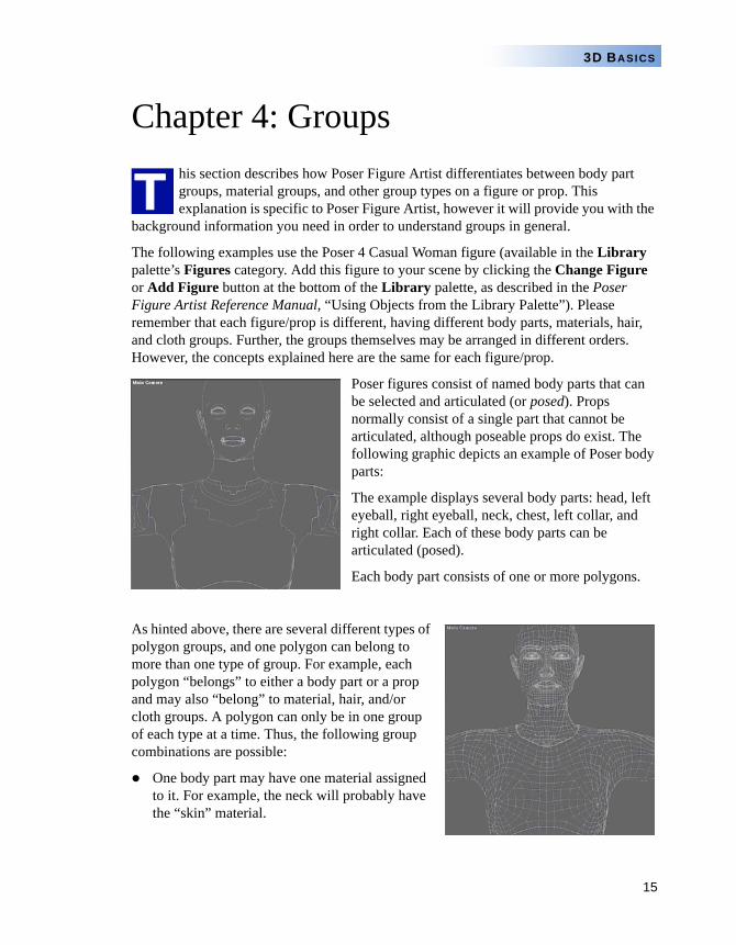
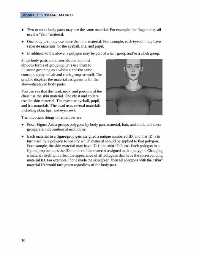
Poser figures consist of named body parts that can be selected and articulated (or posed). Props normally consist of a single part that cannot be articulated, although poseable props do exist. The following graphic depicts an example of Poser body parts:
The example displays several body parts: head, left eyeball, right eyeball, neck, chest, left collar, and right collar. Each of these body parts can be articulated (posed).
Each body part consists of one or more polygons.
As hinted above, there are several different types of polygon groups, and one polygon can belong to more than one type of group. For example, each polygon “belongs” to either a body part or a prop and may also “belong” to material, hair, and/or cloth groups. A polygon can only be in one group of each type at a time. Thus, the following group combinations are possible:
One body part may have one material assigned to it. For example, the neck will probably have the “skin” material.
T
16
POSER 7 TUTORIAL MANUAL
Two or more body parts may use the same material. For example, the fingers may all use the “skin” material.
One body part may use more than one material. For example, each eyeball may have separate materials for the eyeball, iris, and pupil.
In addition to the above, a polygon may be part of a hair group and/or a cloth group.
Since body parts and materials are the most obvious forms of grouping, let’s use them to illustrate grouping as a whole since the same concepts apply to hair and cloth groups as well. The graphic displays the material assignments for the above-displayed body parts.
You can see that the head, neck, and portions of the chest use the skin material. The chest and collars use the shirt material. The eyes use eyeball, pupil, and iris materials. The head uses several materials including skin, lips, and eyebrows.
The important things to remember are:
Poser Figure Artist groups polygons by body part, material, hair, and cloth, and these groups are independent of each other.
Each material in a figure/prop gets assigned a unique numbered ID, and that ID is in turn used by a polygon to specify which material should be applied to that polygon. For example, the skin material may have ID 1, the shirt ID 2, etc. Each polygon in a figure/prop includes the ID number of the material assigned to that polygon. Changing a material itself will affect the appearance of all polygons that have the corresponding material ID. For example, if one made the skin green, then all polygons with the “skin” material ID would turn green regardless of the body part.
17
3D BASICS
The following table depicts a partial list of the relationships between body parts and materials in the Poser 4 Casual Woman figure:
Again, the only relationship between the body parts, materials, hair, and cloth is that defined by the figure’s creator. Poser Figure Artist does not mandate any such relationship.
Now that we have differentiated between body part and material groups and mentioned hair and cloth, let’s describe hair and cloth groups in more detail:
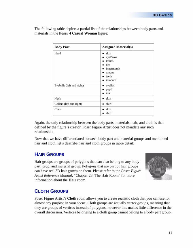
HAIR GROUPS
Hair groups are groups of polygons that can also belong to any body part, prop, and material group. Polygons that are part of hair groups can have real 3D hair grown on them. Please refer to the Poser Figure Artist Reference Manual, “Chapter 28: The Hair Room” for more information about the Hair room.
CLOTH GROUPS
Poser Figure Artist’s Cloth room allows you to create realistic cloth that you can use for almost any purpose in your scene. Cloth groups are actually vertex groups, meaning that they are groups of vertices instead of polygons, however this makes little difference in the overall discussion. Vertices belonging to a cloth group cannot belong to a body part group.
Body Part Assigned Material(s)
Head skineyeBrowlasheslipsinnermouthtongueteethinmouth
Eyeballs (left and right) eyeBallpupiliris
Neck skin
Collars (left and right) shirt
Chest skinshirt
18
POSER 7 TUTORIAL MANUAL
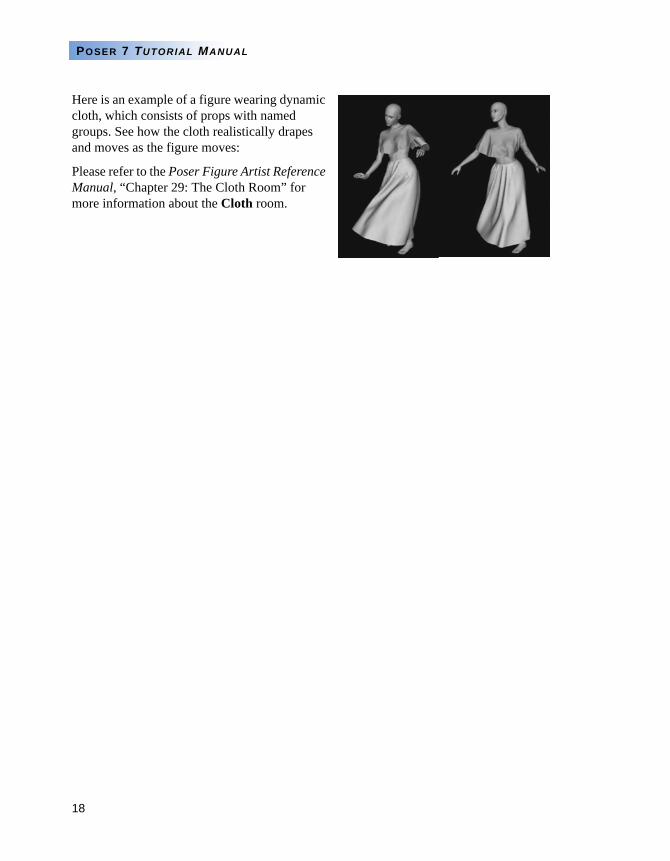
Here is an example of a figure wearing dynamic cloth, which consists of props with named groups. See how the cloth realistically drapes and moves as the figure moves:
Please refer to the Poser Figure Artist Reference Manual, “Chapter 29: The Cloth Room” for more information about the Cloth room.
19
3D BASICS
Chapter 5: Multi/Sub-object Materials
ach figure/prop has its own unique material list containing individual materials within that list. You can see this for yourself by creating a Poser Figure Artist scene with two or more figures/
props and opening the Material room.
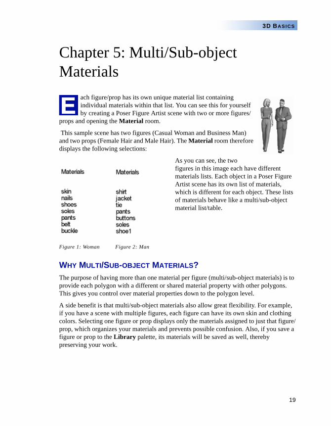
This sample scene has two figures (Casual Woman and Business Man) and two props (Female Hair and Male Hair). The Material room therefore displays the following selections:
As you can see, the two figures in this image each have different materials lists. Each object in a Poser Figure Artist scene has its own list of materials, which is different for each object. These lists of materials behave like a multi/sub-object material list/table.
Figure 1: Woman Figure 2: Man
WHY MULTI/SUB-OBJECT MATERIALS?The purpose of having more than one material per figure (multi/sub-object materials) is to provide each polygon with a different or shared material property with other polygons. This gives you control over material properties down to the polygon level.
A side benefit is that multi/sub-object materials also allow great flexibility. For example, if you have a scene with multiple figures, each figure can have its own skin and clothing colors. Selecting one figure or prop displays only the materials assigned to just that figure/prop, which organizes your materials and prevents possible confusion. Also, if you save a figure or prop to the Library palette, its materials will be saved as well, thereby preserving your work.
E
20
POSER 7 TUTORIAL MANUAL
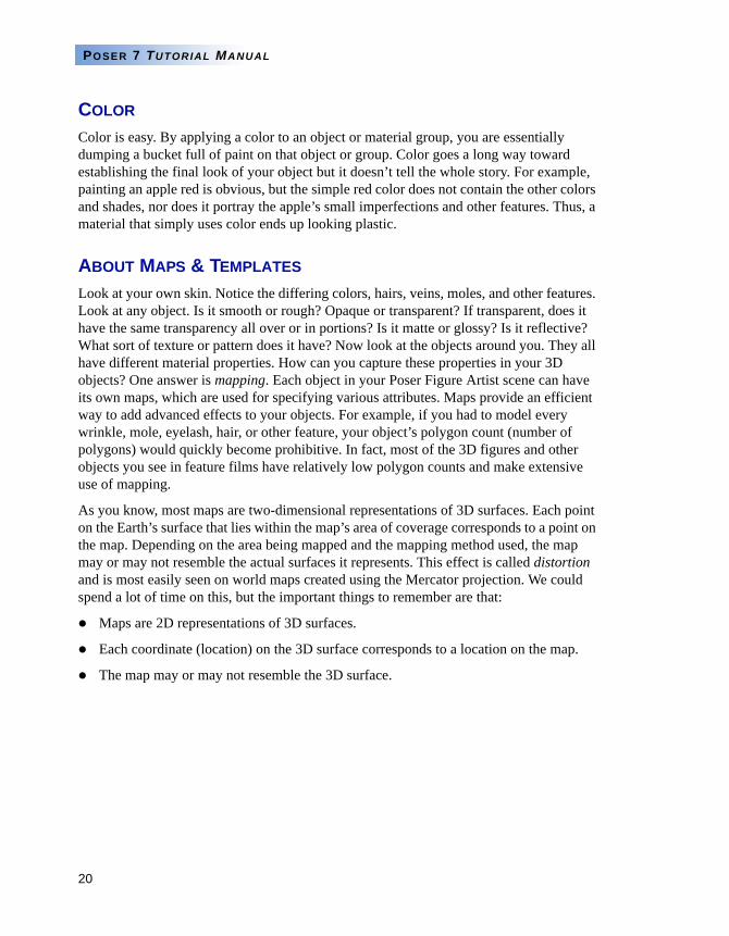
COLOR
Color is easy. By applying a color to an object or material group, you are essentially dumping a bucket full of paint on that object or group. Color goes a long way toward establishing the final look of your object but it doesn’t tell the whole story. For example, painting an apple red is obvious, but the simple red color does not contain the other colors and shades, nor does it portray the apple’s small imperfections and other features. Thus, a material that simply uses color ends up looking plastic.
ABOUT MAPS & TEMPLATES
Look at your own skin. Notice the differing colors, hairs, veins, moles, and other features. Look at any object. Is it smooth or rough? Opaque or transparent? If transparent, does it have the same transparency all over or in portions? Is it matte or glossy? Is it reflective? What sort of texture or pattern does it have? Now look at the objects around you. They all have different material properties. How can you capture these properties in your 3D objects? One answer is mapping. Each object in your Poser Figure Artist scene can have its own maps, which are used for specifying various attributes. Maps provide an efficient way to add advanced effects to your objects. For example, if you had to model every wrinkle, mole, eyelash, hair, or other feature, your object’s polygon count (number of polygons) would quickly become prohibitive. In fact, most of the 3D figures and other objects you see in feature films have relatively low polygon counts and make extensive use of mapping.
As you know, most maps are two-dimensional representations of 3D surfaces. Each point on the Earth’s surface that lies within the map’s area of coverage corresponds to a point on the map. Depending on the area being mapped and the mapping method used, the map may or may not resemble the actual surfaces it represents. This effect is called distortion and is most easily seen on world maps created using the Mercator projection. We could spend a lot of time on this, but the important things to remember are that:
Maps are 2D representations of 3D surfaces.
Each coordinate (location) on the 3D surface corresponds to a location on the map.
The map may or may not resemble the 3D surface.
21
3D BASICS
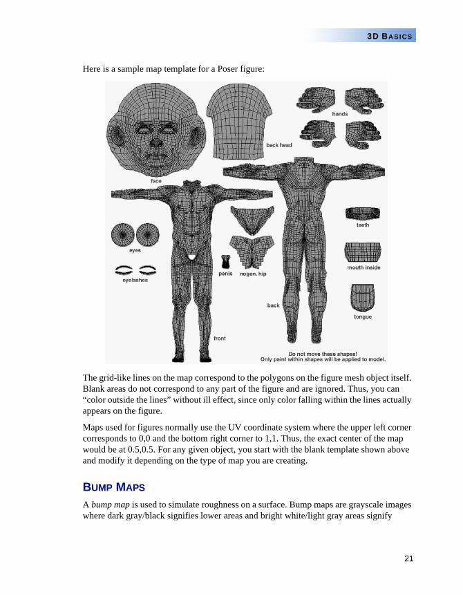
Here is a sample map template for a Poser figure:
The grid-like lines on the map correspond to the polygons on the figure mesh object itself. Blank areas do not correspond to any part of the figure and are ignored. Thus, you can “color outside the lines” without ill effect, since only color falling within the lines actually appears on the figure.
Maps used for figures normally use the UV coordinate system where the upper left corner corresponds to 0,0 and the bottom right corner to 1,1. Thus, the exact center of the map would be at 0.5,0.5. For any given object, you start with the blank template shown above and modify it depending on the type of map you are creating.
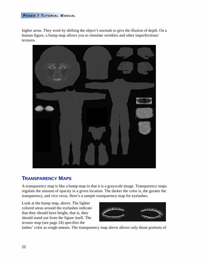
BUMP MAPS
A bump map is used to simulate roughness on a surface. Bump maps are grayscale images where dark gray/black signifies lower areas and bright white/light gray areas signify
22
POSER 7 TUTORIAL MANUAL
higher areas. They work by shifting the object’s normals to give the illusion of depth. On a human figure, a bump map allows you to simulate wrinkles and other imperfections/textures.
TRANSPARENCY MAPS
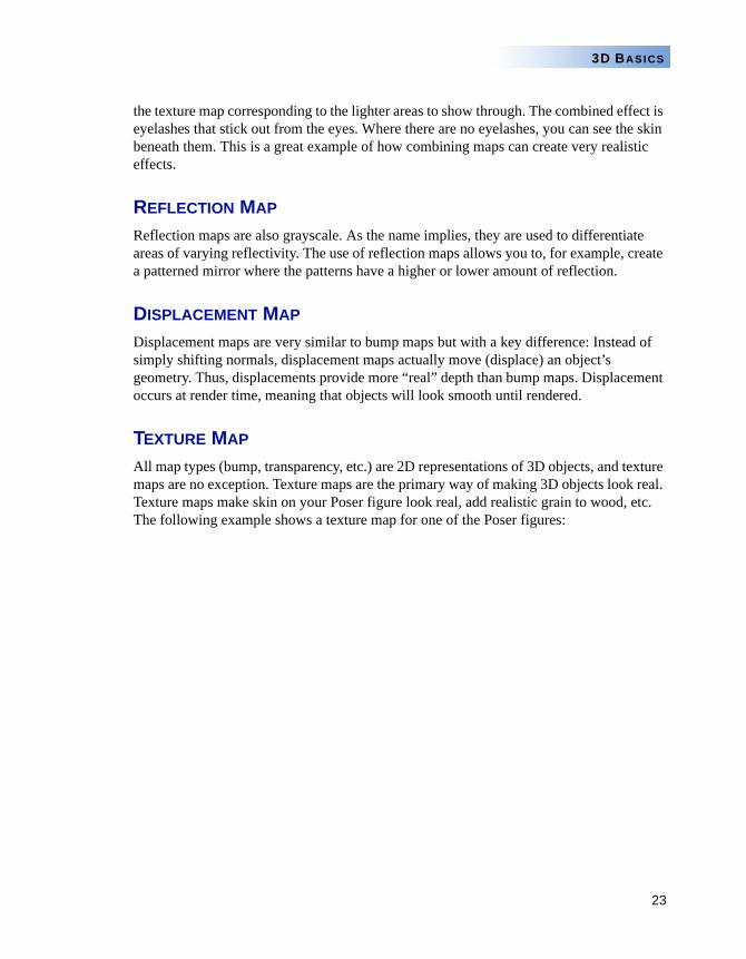
A transparency map is like a bump map in that it is a grayscale image. Transparency maps regulate the amount of opacity in a given location. The darker the color is, the greater the transparency, and vice versa. Here’s a sample transparency map for eyelashes.
Look at the bump map, above. The lighter colored areas around the eyelashes indicate that they should have height, that is, they should stand out from the figure itself. The texture map (see page 24) specifies the lashes’ color as rough smears. The transparency map above allows only those portions of
23
3D BASICS
the texture map corresponding to the lighter areas to show through. The combined effect is eyelashes that stick out from the eyes. Where there are no eyelashes, you can see the skin beneath them. This is a great example of how combining maps can create very realistic effects.
REFLECTION MAP
Reflection maps are also grayscale. As the name implies, they are used to differentiate areas of varying reflectivity. The use of reflection maps allows you to, for example, create a patterned mirror where the patterns have a higher or lower amount of reflection.
DISPLACEMENT MAP
Displacement maps are very similar to bump maps but with a key difference: Instead of simply shifting normals, displacement maps actually move (displace) an object’s geometry. Thus, displacements provide more “real” depth than bump maps. Displacement occurs at render time, meaning that objects will look smooth until rendered.
TEXTURE MAP
All map types (bump, transparency, etc.) are 2D representations of 3D objects, and texture maps are no exception. Texture maps are the primary way of making 3D objects look real. Texture maps make skin on your Poser figure look real, add realistic grain to wood, etc. The following example shows a texture map for one of the Poser figures:

24
POSER 7 TUTORIAL MANUAL
You can use shader elements such as color to get an effect without using texture maps, but you won’t be able to precisely place features where you want them (such as painted fingernails on the ends of the fingers).
NOTETEXTURE MAPS ARE FULLY COLORED, UNLIKE THE GRAYSCALE EXAMPLE SHOWN ABOVE.
25
3D BASICS
PROCEDURAL SHADERS
Poser Figure Artist’s FireFly rendering engine supports the use of procedural shaders (or shaders for short). Shaders consist of a root node that can be modified by adding additional nodes that modify one or more of the root node’s values. A node’s output can modify one or more nodes, and you can use more than one node to influence another. You can include all of the maps we’ve discussed above when building shaders. You can also create realistic materials that don’t require any maps at all, or you can have other nodes modifying any maps you decide to use. Thus, shaders are a second method of creating materials that may or may not integrate maps. Please refer to the Poser Figure Artist Reference Manual, “Chapter 26: The Material Room” for information about Poser Figure Artist’s Material room.
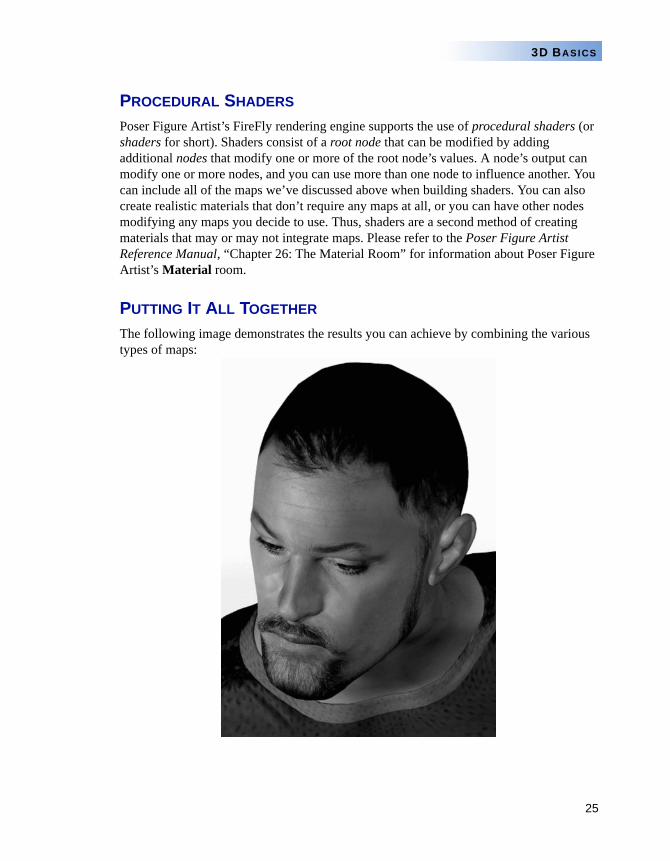
PUTTING IT ALL TOGETHER
The following image demonstrates the results you can achieve by combining the various types of maps:
PART 2
Basic Poser 7Operations
27
BASIC POSER 7 OPERATIONS
Chapter 6: Poser 7 Operations Tutorial
elcome to the Poser 7 Operations Tutorial. This tutorial is designed to introduce all the major features and functions in Poser 7. Its main goal is to teach you the techniques you need to know to create realistic poses and animations.
This Tutorial chapter is divided into two sections:
The Basics, which contains a basic tutorial to help you get started using Poser 7.
Advanced Tutorials, which lead you through figure modification and animation.
THE BASICS
The following set of lessons is designed to help you learn the basic operations in Poser 7. They cover topics such as working with posing and scene development tools.
LESSON 1: WORKING WITH CAMERAS
You can access the cameras in Poser 7 in several different ways. An often overlooked method of selecting a camera is by using keyboard keys. Learning a few key commands can make viewing a figure much easier.
There are two types of cameras in Poser 7: Conical and Isometric. Conical cameras (such as the Main, Hand and Face cameras) act like real-world cameras in that they display perspective. Isometric cameras (such as From Top, From Left, etc.) have no perspective. When you view figures using Isometric cameras you won’t be able to rotate around the workspace.
Each camera has its own center; it centers on and rotates around an object. For example, the Right Hand camera rotates around the Right Hand, and the Face camera rotates around the face. Both cameras face the center directly unless you intentionally redirect them.
Refer to the Poser 7 Reference Manual, “Cameras” for more on cameras.
In this lesson you’ll explore the Poser 7 workspace using the various cameras.
NOTEUNLESS STATED OTHERWISE, THE TUTORIALS IN THIS SECTION USE THE POSER 4 CASUAL WOMAN FIGURE.
W
28
POSER 7 TUTORIAL MANUAL
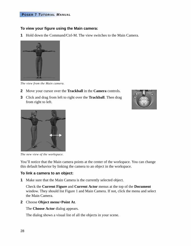
To view your figure using the Main camera:
1 Hold down the Command/Ctrl-M. The view switches to the Main Camera.
2 Move your cursor over the Trackball in the Camera controls.
3 Click and drag from left to right over the Trackball. Then drag from right to left.
You’ll notice that the Main camera points at the center of the workspace. You can change this default behavior by linking the camera to an object in the workspace.
To link a camera to an object:
1 Make sure that the Main Camera is the currently selected object.
Check the Current Figure and Current Actor menus at the top of the Document window. They should list Figure 1 and Main Camera. If not, click the menu and select the Main Camera.
2 Choose Object menu>Point At.
The Choose Actor dialog appears.
The dialog shows a visual list of all the objects in your scene.
The view from the Main camera.
The new view of the workspace.
29
BASIC POSER 7 OPERATIONS
Scroll down until you see the Head element.
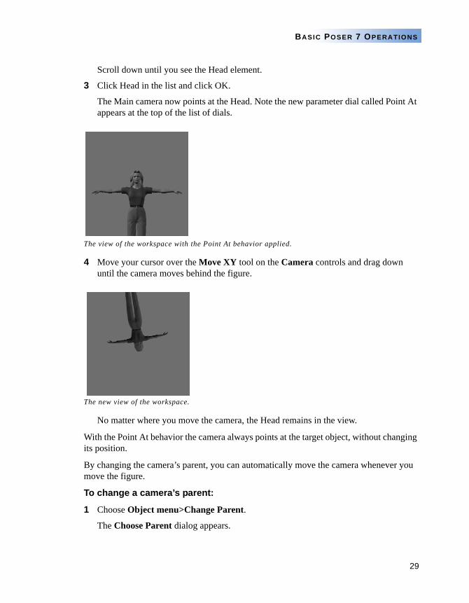
3 Click Head in the list and click OK.
The Main camera now points at the Head. Note the new parameter dial called Point At appears at the top of the list of dials.
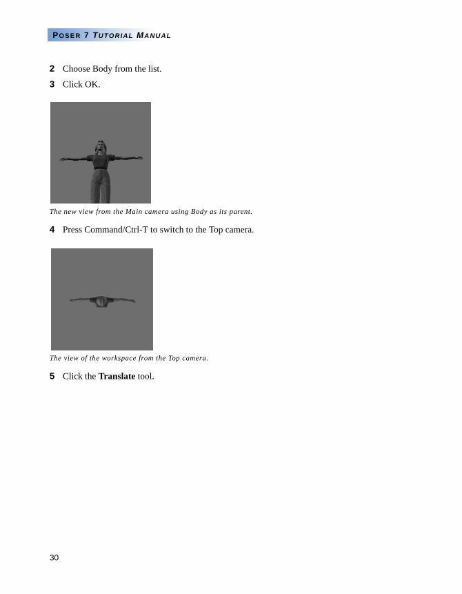
4 Move your cursor over the Move XY tool on the Camera controls and drag down until the camera moves behind the figure.
No matter where you move the camera, the Head remains in the view.
With the Point At behavior the camera always points at the target object, without changing its position.
By changing the camera’s parent, you can automatically move the camera whenever you move the figure.
To change a camera’s parent:
1 Choose Object menu>Change Parent.
The Choose Parent dialog appears.
The view of the workspace with the Point At behavior applied.
The new view of the workspace.
30
POSER 7 TUTORIAL MANUAL
2 Choose Body from the list.
3 Click OK.
4 Press Command/Ctrl-T to switch to the Top camera.
5 Click the Translate tool.
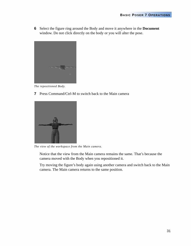
The new view from the Main camera using Body as its parent.
The view of the workspace from the Top camera.
31
BASIC POSER 7 OPERATIONS
6 Select the figure ring around the Body and move it anywhere in the Document window. Do not click directly on the body or you will alter the pose.
7 Press Command/Ctrl-M to switch back to the Main camera
Notice that the view from the Main camera remains the same. That’s because the camera moved with the Body when you repositioned it.
Try moving the figure’s body again using another camera and switch back to the Main camera. The Main camera returns to the same position.
The repositioned Body.
The view of the workspace from the Main camera.
32
POSER 7 TUTORIAL MANUAL
To view the figure using the Face camera:
1 Press Command/Ctrl-(=) to switch to the Face Camera.
2 Click and drag left over the Trackball.
Notice that Face camera always stays with the selected figure, no matter where you move the figure.
The Face Camera is ideal for making animations that center on a single figure.
To view the figure using the Top camera:
1 Press Command/Ctrl-T to switch to the Top camera.
The Top camera, like the Left, Right and Front cameras, is an Isometric camera, meaning that it doesn’t show perspective.
It is designed specifically for viewing a pose rather than rendering poses. This camera is very useful for placing figures, creating animations, and locating Figures and Spotlights you may have lost in the workspace.
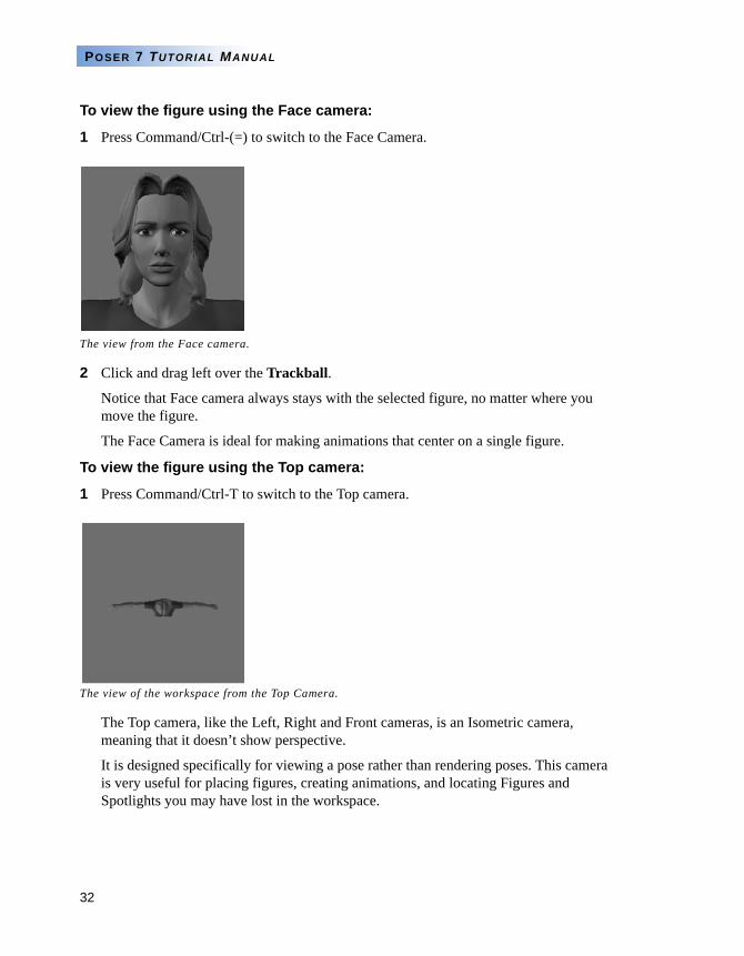
The view from the Face camera.
The view of the workspace from the Top Camera.
33
BASIC POSER 7 OPERATIONS
2 Set the Top camera Scale Parameter Dial to 400% or more to get a wide view of the Poser 7 workspace.
A Note on Focal Lengths
Poser 7’s default cameras are set to 25mm and have all the attributes of a real-world 25mm Wide Angle Lens. You can experiment with other focal lengths such as 50mm, which resembles the human eye’s view, and 100mm, a lens favored by Portrait Photographers.
Each time you set the focal length, the Scale will also reset. Scaling down from 100% to 25% zooms in, while scaling up from 100% to 1000% zooms out.
LESSON 2: TRACKING MODES
A tracking mode determines how the figure looks as you move it. Box Tracking mode displays the figure as boxes all the time. Fast Tracking mode displays the figure as boxes during movement, and uses the currently selected display style when the figure is still. Full Tracking mode displays the figure in the current display style at all times.
Tracking modes help you overcome the limitations of your computer’s processing speed when posing. Faster computers can display better tracking, while slower machines benefit from less complex modes.
In this lesson you’ll learn how to choose a tracking mode.
To set a tracking mode:
1 Click one of the Tracking Mode icons located in the pop-up menu at the bottom left of the Document window.
1 From the top to bottom they are: Box Tracking, Fast Tracking, and Full Tracking.
2 Click each of the mode icons and adjust the figure’s pose. Observe how different modes affect response time.
The expanded view of the workspace.
34
POSER 7 TUTORIAL MANUAL
3 Use the mode that doesn’t slow down your computer’s response time.
WORKING WITH LIGHTS
Lights are one of the most necessary and least understood part of any 3D Program. Often they’re difficult to use. Poser 7’s remedy is unique Lighting controls that let you intuitively manipulate lights.
There are four types of lights available in Poser 7: Infinite lights, Point lights, Spotlights, and Diffuse Image Based Lighting (IBL). To use them effectively, you first need to understand the differences between them. Infinite light illuminates one side of everything in the scene in the same way sunlight does. Point lights emit light from a single point outward in a 360-degree radius. Spotlights point in a single direction and illuminate everything that falls within the cone of light they produce. Diffuse Image Based Lighting uses a 360-degree light distribution map, or light probe, to illuminate the scene. Poser 7 uses infinite lights by default.
LESSON 1: USING THE LIGHT CONTROLS
You’ll begin this lesson by deleting two of the three default lights in the Poser 7 scene and learning the controls.
To use the Light controls:
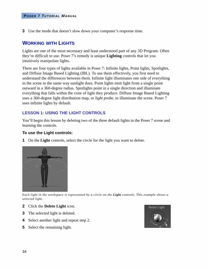
1 On the Light controls, select the circle for the light you want to delete.
2 Click the Delete Light icon.
3 The selected light is deleted.
4 Select another light and repeat step 2.
5 Select the remaining light.
Each light in the workspace is represented by a circle on the Light controls. This example shows a selected light.
35
BASIC POSER 7 OPERATIONS
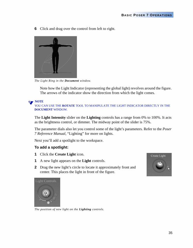
6 Click and drag over the control from left to right.
Note how the Light Indicator (representing the global light) revolves around the figure. The arrows of the indicator show the direction from which the light comes.
NOTEYOU CAN USE THE ROTATE TOOL TO MANIPULATE THE LIGHT INDICATOR DIRECTLY IN THE DOCUMENT WINDOW.
The Light Intensity slider on the Lighting controls has a range from 0% to 100%. It acts as the brightness control, or dimmer. The midway point of the slider is 75%.
The parameter dials also let you control some of the light’s parameters. Refer to the Poser 7 Reference Manual, “Lighting” for more on lights.
Next you’ll add a spotlight to the workspace.
To add a spotlight:
1 Click the Create Light icon.
1 A new light appears on the Light controls.
2 Drag the new light’s circle to locate it approximately front and center. This places the light in front of the figure.
The position of new light on the Lighting controls.
The Light Ring in the Document window.
36
POSER 7 TUTORIAL MANUAL
3 Set the Light Intensity slider to approximately 75%, or the middle of the slider.
The Light Intensity slider set to 75%.
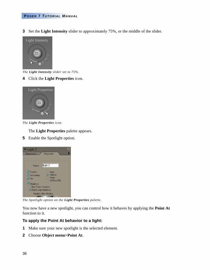
4 Click the Light Properties icon.
The Light Properties palette appears.
5 Enable the Spotlight option.
You now have a new spotlight, you can control how it behaves by applying the Point At function to it.
To apply the Point At behavior to a light:
1 Make sure your new spotlight is the selected element.
2 Choose Object menu>Point At.
The Light Properties icon.
The Spotlight option on the Light Properties palette.
37
BASIC POSER 7 OPERATIONS
The Choose Actor dialog appears.
3 Choose Head from the Select a Scene Element list.
4 Set the yTrans parameter dial to between 0.900 and 1.000.
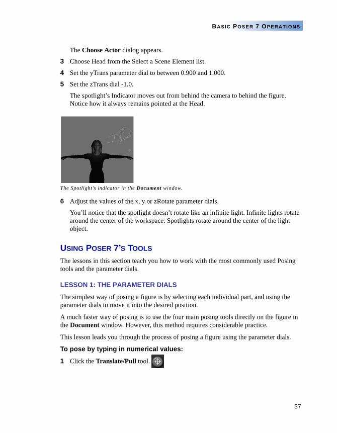
5 Set the zTrans dial -1.0.
The spotlight’s Indicator moves out from behind the camera to behind the figure. Notice how it always remains pointed at the Head.
6 Adjust the values of the x, y or zRotate parameter dials.
You’ll notice that the spotlight doesn’t rotate like an infinite light. Infinite lights rotate around the center of the workspace. Spotlights rotate around the center of the light object.
USING POSER 7’S TOOLS
The lessons in this section teach you how to work with the most commonly used Posing tools and the parameter dials.
LESSON 1: THE PARAMETER DIALS
The simplest way of posing a figure is by selecting each individual part, and using the parameter dials to move it into the desired position.
A much faster way of posing is to use the four main posing tools directly on the figure in the Document window. However, this method requires considerable practice.
This lesson leads you through the process of posing a figure using the parameter dials.
To pose by typing in numerical values:
1 Click the Translate/Pull tool.
The Spotlight’s indicator in the Document window.
38
POSER 7 TUTORIAL MANUAL
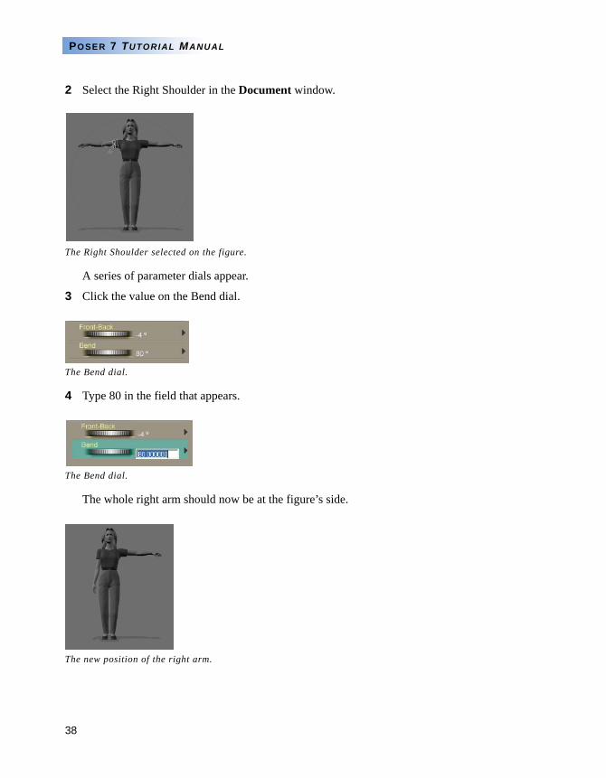
2 Select the Right Shoulder in the Document window.
A series of parameter dials appear.
3 Click the value on the Bend dial.
4 Type 80 in the field that appears.
The whole right arm should now be at the figure’s side.
The Right Shoulder selected on the figure.
The Bend dial.
The Bend dial.
The new position of the right arm.
39
BASIC POSER 7 OPERATIONS
To pose using the dials:
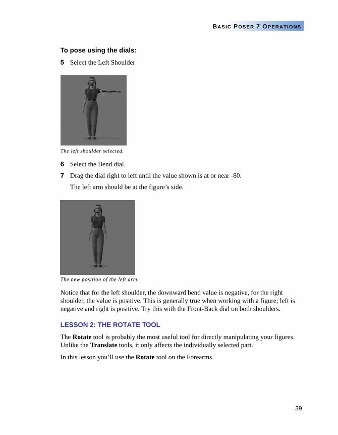
5 Select the Left Shoulder
6 Select the Bend dial.
7 Drag the dial right to left until the value shown is at or near -80.
The left arm should be at the figure’s side.
Notice that for the left shoulder, the downward bend value is negative, for the right shoulder, the value is positive. This is generally true when working with a figure; left is negative and right is positive. Try this with the Front-Back dial on both shoulders.
LESSON 2: THE ROTATE TOOL
The Rotate tool is probably the most useful tool for directly manipulating your figures. Unlike the Translate tools, it only affects the individually selected part.
In this lesson you’ll use the Rotate tool on the Forearms.
The left shoulder selected.
The new position of the left arm.
40
POSER 7 TUTORIAL MANUAL
To pose using the Rotate tool:
1 First, switch to the From Left camera by pressing Command/Ctrl-( ; ). This makes rotating easier.
NOTEBECOMING USED TO QUICKLY CHANGING CAMERAS MAKES POSING A MUCH SIMPLER TASK
You are now looking at the figure’s right side.
2 Click the Rotate tool.
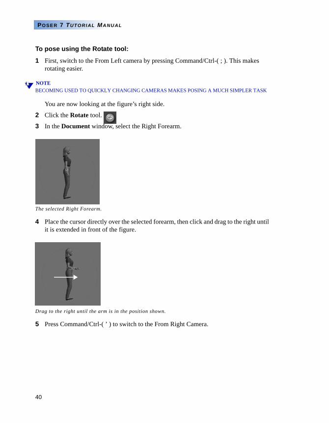
3 In the Document window, select the Right Forearm.
4 Place the cursor directly over the selected forearm, then click and drag to the right until it is extended in front of the figure.
5 Press Command/Ctrl-( ’ ) to switch to the From Right Camera.
The selected Right Forearm.
Drag to the right until the arm is in the position shown.
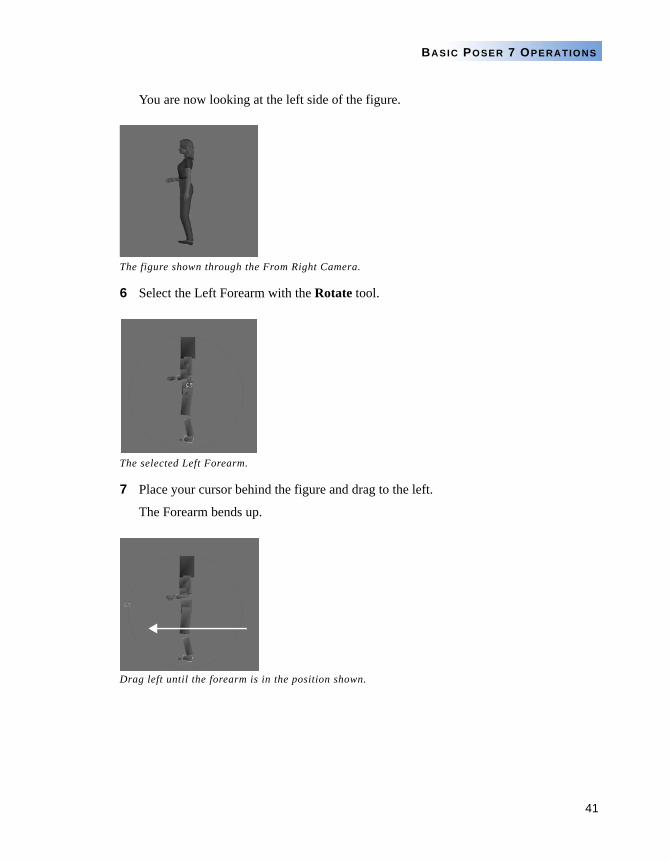
41
BASIC POSER 7 OPERATIONS
You are now looking at the left side of the figure.
6 Select the Left Forearm with the Rotate tool.
7 Place your cursor behind the figure and drag to the left.
The Forearm bends up.
The figure shown through the From Right Camera.
The selected Left Forearm.
Drag left until the forearm is in the position shown.
42
POSER 7 TUTORIAL MANUAL
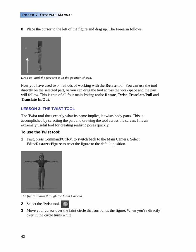
8 Place the cursor to the left of the figure and drag up. The Forearm follows.
Now you have used two methods of working with the Rotate tool. You can use the tool directly on the selected part, or you can drag the tool across the workspace and the part will follow. This is true of all four main Posing tools: Rotate, Twist, Translate/Pull and Translate In/Out.
LESSON 3: THE TWIST TOOL
The Twist tool does exactly what its name implies, it twists body parts. This is accomplished by selecting the part and drawing the tool across the screen. It is an extremely useful tool for creating realistic poses quickly.
To use the Twist tool:
1 First, press Command/Ctrl-M to switch back to the Main Camera. Select Edit>Restore>Figure to reset the figure to the default position.
2 Select the Twist tool.
3 Move your cursor over the faint circle that surrounds the figure. When you’re directly over it, the circle turns white.
Drag up until the forearm is in the position shown.
The figure shown through the Main Camera.
43
BASIC POSER 7 OPERATIONS
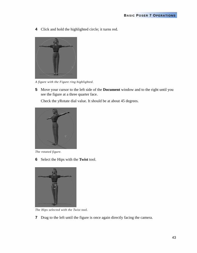
4 Click and hold the highlighted circle; it turns red.
5 Move your cursor to the left side of the Document window and to the right until you see the figure at a three quarter face.
Check the yRotate dial value. It should be at about 45 degrees.
6 Select the Hips with the Twist tool.
7 Drag to the left until the figure is once again directly facing the camera.
A figure with the Figure ring highlighted.
The rotated figure.
The Hips selected with the Twist tool.
44
POSER 7 TUTORIAL MANUAL
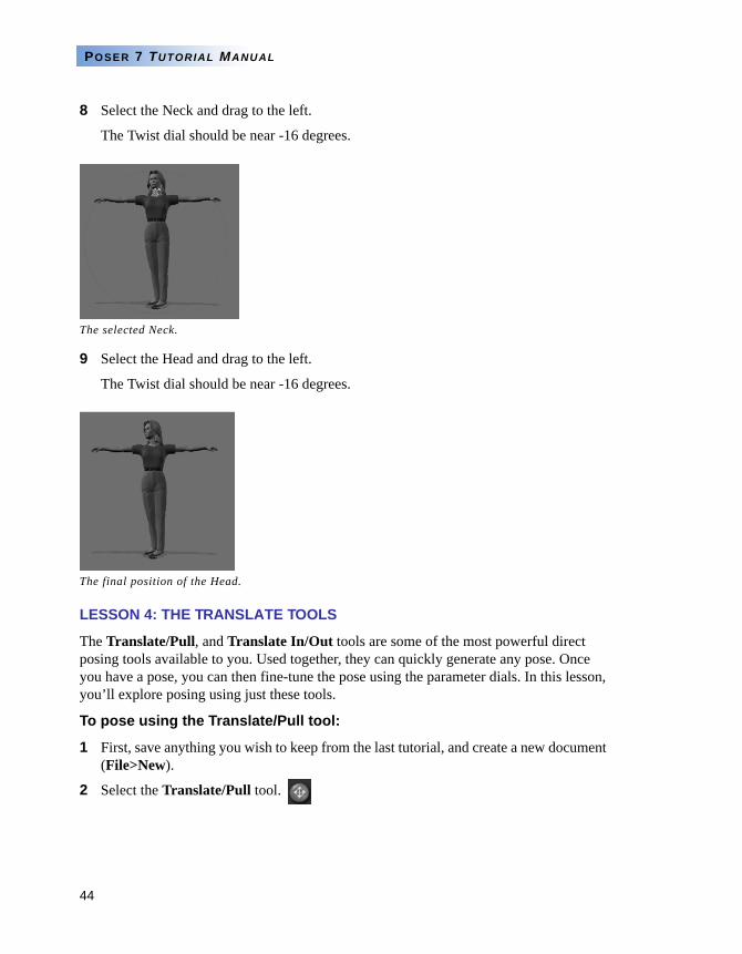
8 Select the Neck and drag to the left.
The Twist dial should be near -16 degrees.
9 Select the Head and drag to the left.
The Twist dial should be near -16 degrees.
LESSON 4: THE TRANSLATE TOOLS
The Translate/Pull, and Translate In/Out tools are some of the most powerful direct posing tools available to you. Used together, they can quickly generate any pose. Once you have a pose, you can then fine-tune the pose using the parameter dials. In this lesson, you’ll explore posing using just these tools.
To pose using the Translate/Pull tool:
1 First, save anything you wish to keep from the last tutorial, and create a new document (File>New).
2 Select the Translate/Pull tool.
The selected Neck.
The final position of the Head.
45
BASIC POSER 7 OPERATIONS
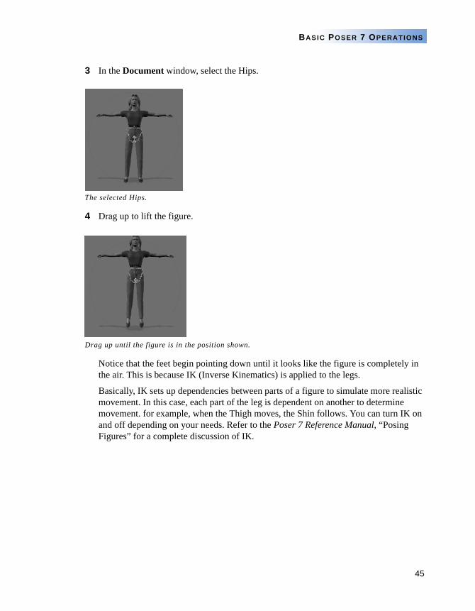
3 In the Document window, select the Hips.
4 Drag up to lift the figure.
Notice that the feet begin pointing down until it looks like the figure is completely in the air. This is because IK (Inverse Kinematics) is applied to the legs.
Basically, IK sets up dependencies between parts of a figure to simulate more realistic movement. In this case, each part of the leg is dependent on another to determine movement. for example, when the Thigh moves, the Shin follows. You can turn IK on and off depending on your needs. Refer to the Poser 7 Reference Manual, “Posing Figures” for a complete discussion of IK.
The selected Hips.
Drag up until the figure is in the position shown.
46
POSER 7 TUTORIAL MANUAL
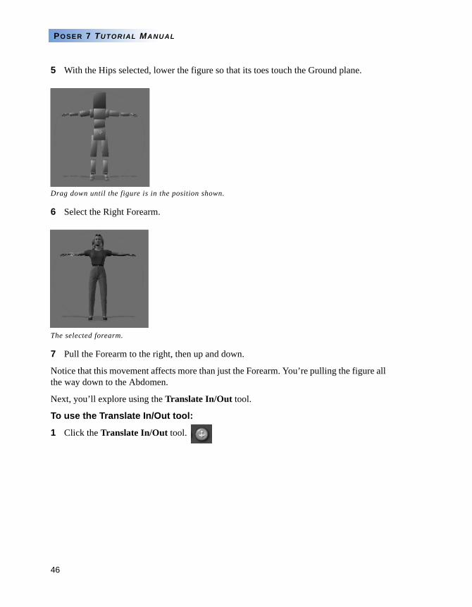
5 With the Hips selected, lower the figure so that its toes touch the Ground plane.
6 Select the Right Forearm.
7 Pull the Forearm to the right, then up and down.
Notice that this movement affects more than just the Forearm. You’re pulling the figure all the way down to the Abdomen.
Next, you’ll explore using the Translate In/Out tool.
To use the Translate In/Out tool:
1 Click the Translate In/Out tool.
Drag down until the figure is in the position shown.
The selected forearm.
47
BASIC POSER 7 OPERATIONS
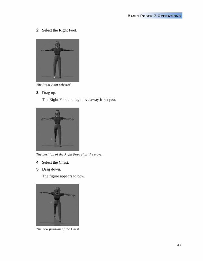
2 Select the Right Foot.
3 Drag up.
The Right Foot and leg move away from you.
4 Select the Chest.
5 Drag down.
The figure appears to bow.
The Right Foot selected.
The position of the Right Foot after the move.
The new position of the Chest.
48
POSER 7 TUTORIAL MANUAL
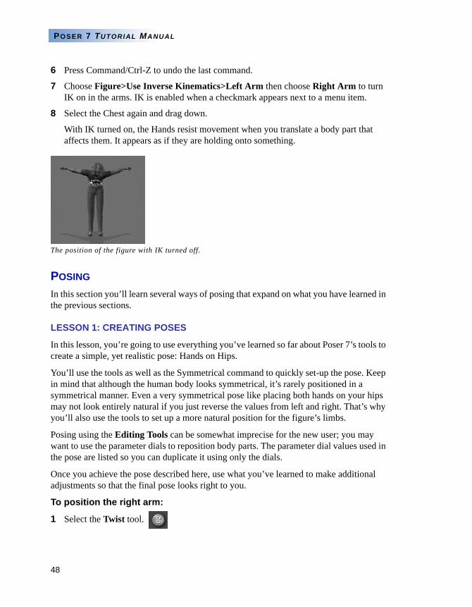
6 Press Command/Ctrl-Z to undo the last command.
7 Choose Figure>Use Inverse Kinematics>Left Arm then choose Right Arm to turn IK on in the arms. IK is enabled when a checkmark appears next to a menu item.
8 Select the Chest again and drag down.
With IK turned on, the Hands resist movement when you translate a body part that affects them. It appears as if they are holding onto something.
POSING
In this section you’ll learn several ways of posing that expand on what you have learned in the previous sections.
LESSON 1: CREATING POSES
In this lesson, you’re going to use everything you’ve learned so far about Poser 7’s tools to create a simple, yet realistic pose: Hands on Hips.
You’ll use the tools as well as the Symmetrical command to quickly set-up the pose. Keep in mind that although the human body looks symmetrical, it’s rarely positioned in a symmetrical manner. Even a very symmetrical pose like placing both hands on your hips may not look entirely natural if you just reverse the values from left and right. That’s why you’ll also use the tools to set up a more natural position for the figure’s limbs.
Posing using the Editing Tools can be somewhat imprecise for the new user; you may want to use the parameter dials to reposition body parts. The parameter dial values used in the pose are listed so you can duplicate it using only the dials.
Once you achieve the pose described here, use what you’ve learned to make additional adjustments so that the final pose looks right to you.
To position the right arm:
1 Select the Twist tool.
The position of the figure with IK turned off.
49
BASIC POSER 7 OPERATIONS
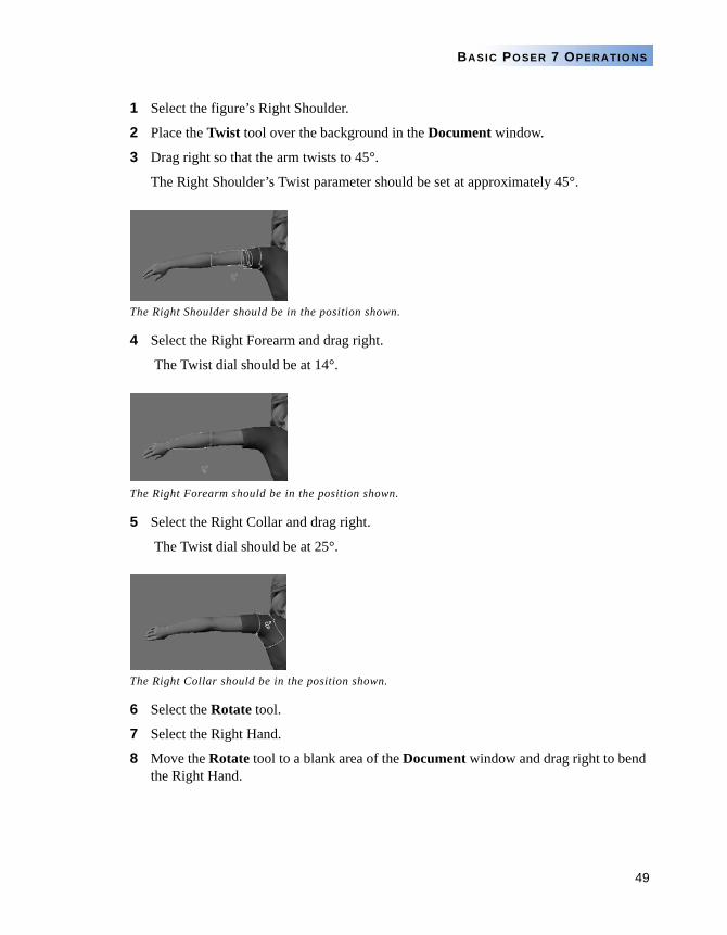
1 Select the figure’s Right Shoulder.
2 Place the Twist tool over the background in the Document window.
3 Drag right so that the arm twists to 45°.
The Right Shoulder’s Twist parameter should be set at approximately 45°.
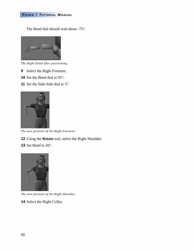
4 Select the Right Forearm and drag right.
The Twist dial should be at 14°.
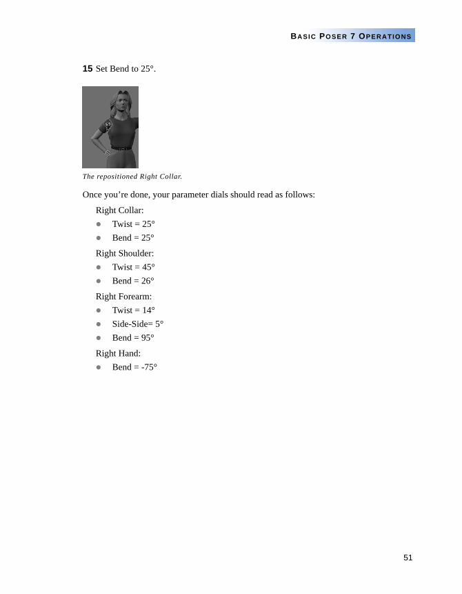
5 Select the Right Collar and drag right.
The Twist dial should be at 25°.
6 Select the Rotate tool.
7 Select the Right Hand.
8 Move the Rotate tool to a blank area of the Document window and drag right to bend the Right Hand.
The Right Shoulder should be in the position shown.
The Right Forearm should be in the position shown.
The Right Collar should be in the position shown.
50
POSER 7 TUTORIAL MANUAL
The Bend dial should read about -75°.
9 Select the Right Forearm.
10 Set the Bend dial to 95°.
11 Set the Side-Side dial to 5°.
12 Using the Rotate tool, select the Right Shoulder.
13 Set Bend to 26°.
14 Select the Right Collar.
The Right Hand after positioning.
The new position of the Right Forearm.
The new position of the Right Shoulder.
51
BASIC POSER 7 OPERATIONS
15 Set Bend to 25°.
Once you’re done, your parameter dials should read as follows:
Right Collar:Twist = 25°Bend = 25°
Right Shoulder:Twist = 45°Bend = 26°
Right Forearm:Twist = 14°Side-Side= 5°Bend = 95°
Right Hand:Bend = -75°
The repositioned Right Collar.
52
POSER 7 TUTORIAL MANUAL
To apply the right arm pose to the left arm:
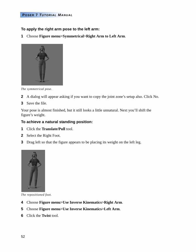
1 Choose Figure menu>Symmetrical>Right Arm to Left Arm.
2 A dialog will appear asking if you want to copy the joint zone’s setup also. Click No.
3 Save the file.
Your pose is almost finished, but it still looks a little unnatural. Next you’ll shift the figure’s weight.
To achieve a natural standing position:
1 Click the Translate/Pull tool.
2 Select the Right Foot.
3 Drag left so that the figure appears to be placing its weight on the left leg.
4 Choose Figure menu>Use Inverse Kinematics>Right Arm.
5 Choose Figure menu>Use Inverse Kinematics>Left Arm.
6 Click the Twist tool.
The symmetrical pose.
The repositioned foot.
53
BASIC POSER 7 OPERATIONS
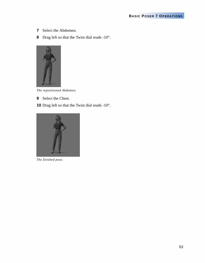
7 Select the Abdomen.
8 Drag left so that the Twist dial reads -10°.
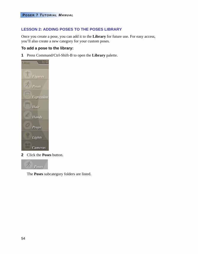
9 Select the Chest.
10 Drag left so that the Twist dial reads -10°.
The repositioned Abdomen.
The finished pose.
54
POSER 7 TUTORIAL MANUAL
LESSON 2: ADDING POSES TO THE POSES LIBRARY
Once you create a pose, you can add it to the Library for future use. For easy access, you’ll also create a new category for your custom poses.
To add a pose to the library:
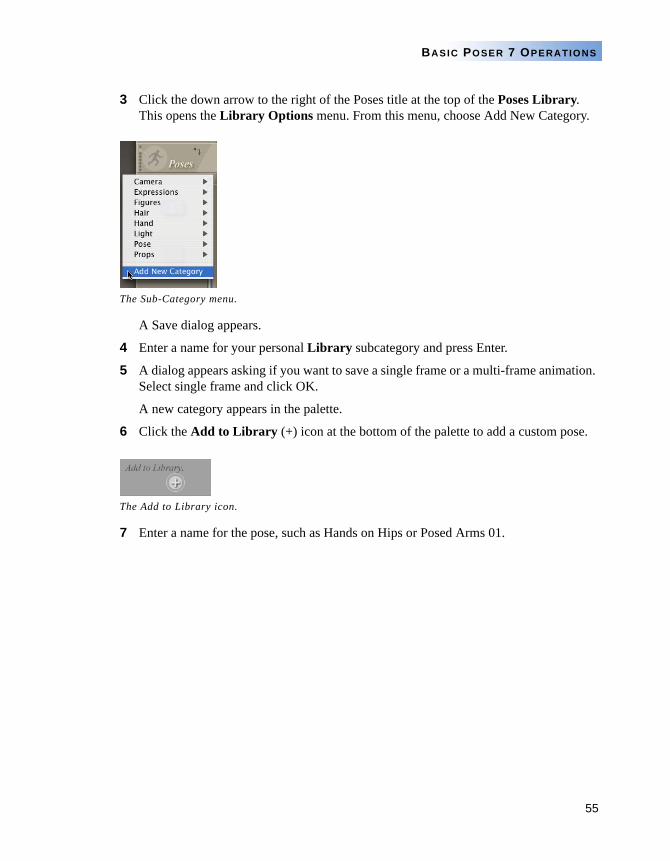
1 Press Command/Ctrl-Shift-B to open the Library palette.
2 Click the Poses button.
The Poses subcategory folders are listed.
55
BASIC POSER 7 OPERATIONS
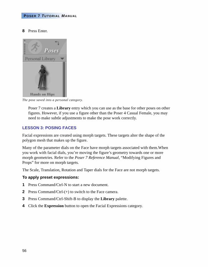
3 Click the down arrow to the right of the Poses title at the top of the Poses Library. This opens the Library Options menu. From this menu, choose Add New Category.
A Save dialog appears.
4 Enter a name for your personal Library subcategory and press Enter.
5 A dialog appears asking if you want to save a single frame or a multi-frame animation. Select single frame and click OK.
A new category appears in the palette.
6 Click the Add to Library (+) icon at the bottom of the palette to add a custom pose.
7 Enter a name for the pose, such as Hands on Hips or Posed Arms 01.
The Sub-Category menu.
The Add to Library icon.
56
POSER 7 TUTORIAL MANUAL
8 Press Enter.
Poser 7 creates a Library entry which you can use as the base for other poses on other figures. However, if you use a figure other than the Poser 4 Casual Female, you may need to make subtle adjustments to make the pose work correctly.
LESSON 3: POSING FACES
Facial expressions are created using morph targets. These targets alter the shape of the polygon mesh that makes up the figure.
Many of the parameter dials on the Face have morph targets associated with them.When you work with facial dials, you’re moving the figure’s geometry towards one or more morph geometries. Refer to the Poser 7 Reference Manual, “Modifying Figures and Props” for more on morph targets.
The Scale, Translation, Rotation and Taper dials for the Face are not morph targets.
To apply preset expressions:
1 Press Command/Ctrl-N to start a new document.
2 Press Command/Ctrl-(+) to switch to the Face camera.
3 Press Command/Ctrl-Shift-B to display the Library palette.
4 Click the Expression button to open the Facial Expressions category.
The pose saved into a personal category.
57
BASIC POSER 7 OPERATIONS
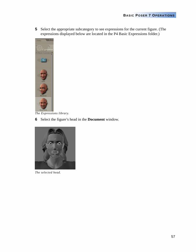
5 Select the appropriate subcategory to see expressions for the current figure. (The expressions displayed below are located in the P4 Basic Expressions folder.)
The Expressions library.
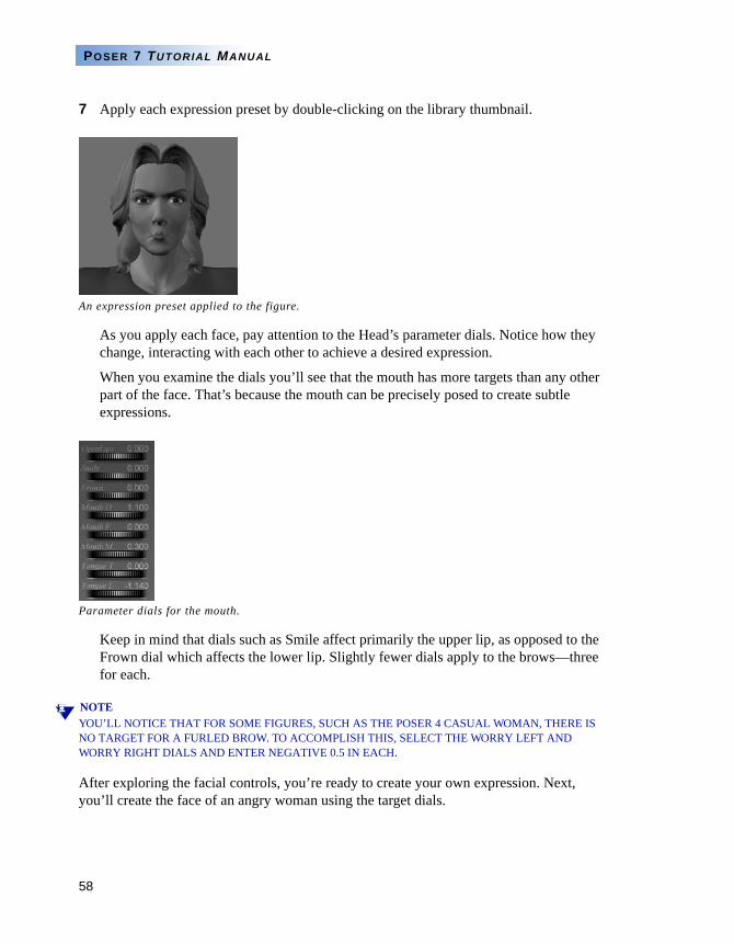
6 Select the figure’s head in the Document window.
The selected head.
58
POSER 7 TUTORIAL MANUAL
7 Apply each expression preset by double-clicking on the library thumbnail.
As you apply each face, pay attention to the Head’s parameter dials. Notice how they change, interacting with each other to achieve a desired expression.
When you examine the dials you’ll see that the mouth has more targets than any other part of the face. That’s because the mouth can be precisely posed to create subtle expressions.
Keep in mind that dials such as Smile affect primarily the upper lip, as opposed to the Frown dial which affects the lower lip. Slightly fewer dials apply to the brows—three for each.
NOTEYOU’LL NOTICE THAT FOR SOME FIGURES, SUCH AS THE POSER 4 CASUAL WOMAN, THERE IS NO TARGET FOR A FURLED BROW. TO ACCOMPLISH THIS, SELECT THE WORRY LEFT AND WORRY RIGHT DIALS AND ENTER NEGATIVE 0.5 IN EACH.
After exploring the facial controls, you’re ready to create your own expression. Next, you’ll create the face of an angry woman using the target dials.
An expression preset applied to the figure.
Parameter dials for the mouth.
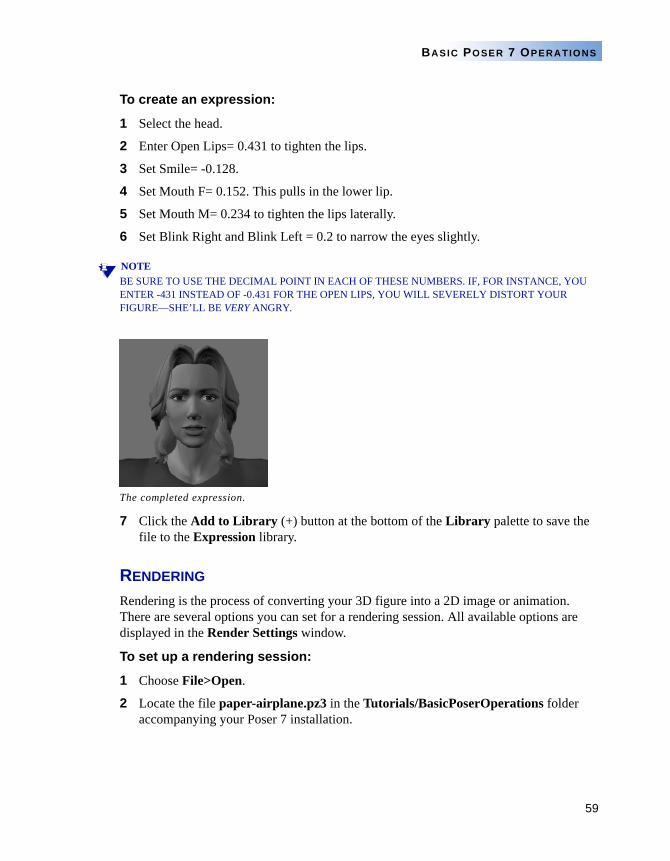
59
BASIC POSER 7 OPERATIONS
To create an expression:
1 Select the head.
2 Enter Open Lips= 0.431 to tighten the lips.
3 Set Smile= -0.128.
4 Set Mouth F= 0.152. This pulls in the lower lip.
5 Set Mouth M= 0.234 to tighten the lips laterally.
6 Set Blink Right and Blink Left = 0.2 to narrow the eyes slightly.
NOTEBE SURE TO USE THE DECIMAL POINT IN EACH OF THESE NUMBERS. IF, FOR INSTANCE, YOU ENTER -431 INSTEAD OF -0.431 FOR THE OPEN LIPS, YOU WILL SEVERELY DISTORT YOUR FIGURE—SHE’LL BE VERY ANGRY.
7 Click the Add to Library (+) button at the bottom of the Library palette to save the file to the Expression library.
RENDERING
Rendering is the process of converting your 3D figure into a 2D image or animation. There are several options you can set for a rendering session. All available options are displayed in the Render Settings window.
To set up a rendering session:
1 Choose File>Open.
2 Locate the file paper-airplane.pz3 in the Tutorials/BasicPoserOperations folder accompanying your Poser 7 installation.
The completed expression.
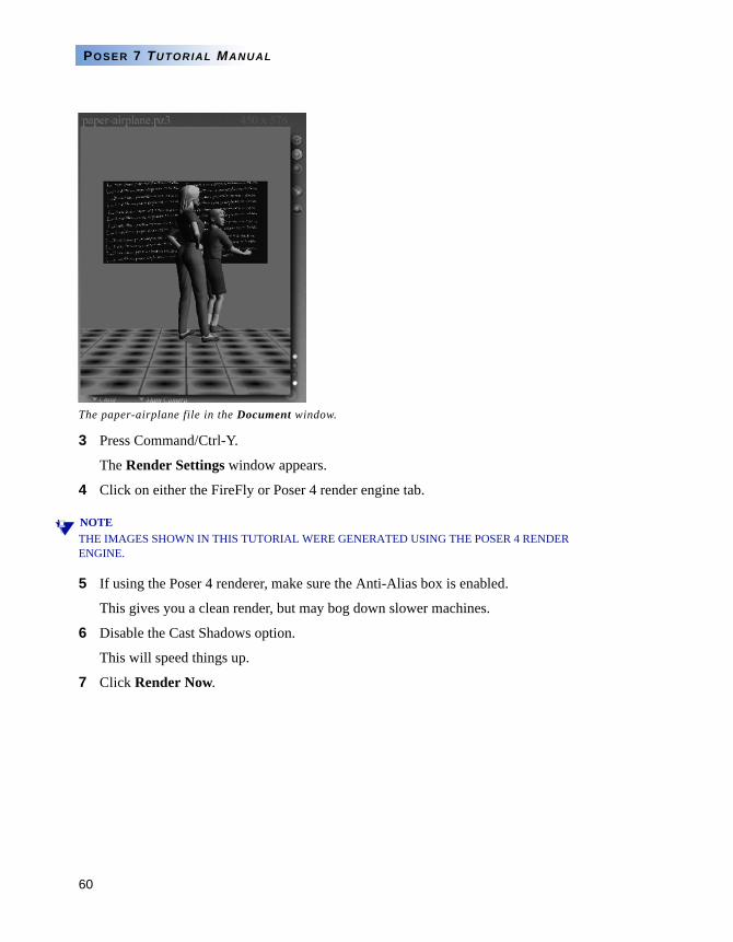
60
POSER 7 TUTORIAL MANUAL
3 Press Command/Ctrl-Y.
The Render Settings window appears.
4 Click on either the FireFly or Poser 4 render engine tab.
NOTETHE IMAGES SHOWN IN THIS TUTORIAL WERE GENERATED USING THE POSER 4 RENDER ENGINE.
5 If using the Poser 4 renderer, make sure the Anti-Alias box is enabled.
This gives you a clean render, but may bog down slower machines.
6 Disable the Cast Shadows option.
This will speed things up.
7 Click Render Now.
The paper-airplane file in the Document window.
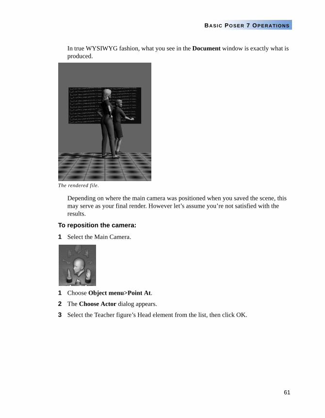
61
BASIC POSER 7 OPERATIONS
In true WYSIWYG fashion, what you see in the Document window is exactly what is produced.
Depending on where the main camera was positioned when you saved the scene, this may serve as your final render. However let’s assume you’re not satisfied with the results.
To reposition the camera:
1 Select the Main Camera.
1 Choose Object menu>Point At.
2 The Choose Actor dialog appears.
3 Select the Teacher figure’s Head element from the list, then click OK.
The rendered file.
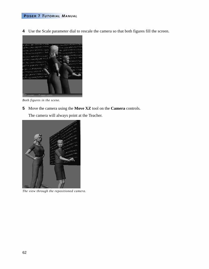
62
POSER 7 TUTORIAL MANUAL
4 Use the Scale parameter dial to rescale the camera so that both figures fill the screen.
5 Move the camera using the Move XZ tool on the Camera controls.
The camera will always point at the Teacher.
Both figures in the scene.
The view through the repositioned camera.
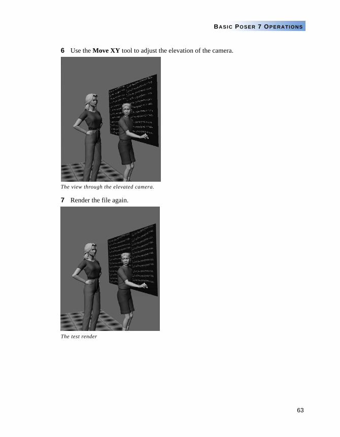
63
BASIC POSER 7 OPERATIONS
6 Use the Move XY tool to adjust the elevation of the camera.
7 Render the file again.
The view through the elevated camera.
The test render
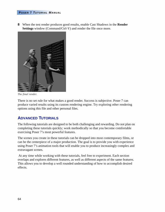
64
POSER 7 TUTORIAL MANUAL
8 When the test render produces good results, enable Cast Shadows in the Render Settings window (Command/Ctrl-Y) and render the file once more.
There is no set rule for what makes a good render. Success is subjective. Poser 7 can produce varied results using its custom rendering engine. Try exploring other rendering options using this file and other personal files.
ADVANCED TUTORIALS
The following tutorials are designed to be both challenging and rewarding. Do not plan on completing these tutorials quickly; work methodically so that you become comfortable exercising Poser 7’s most powerful features.
The scenes you create in these tutorials can be dropped into most contemporary films, or can be the centerpiece of a major production. The goal is to provide you with experience using Poser 7’s animation tools that will enable you to produce increasingly complex and extravagant scenes.
At any time while working with these tutorials, feel free to experiment. Each section overlaps and explores different features, as well as different aspects of the same features. This allows you to develop a well rounded understanding of how to accomplish desired effects.
The final render.
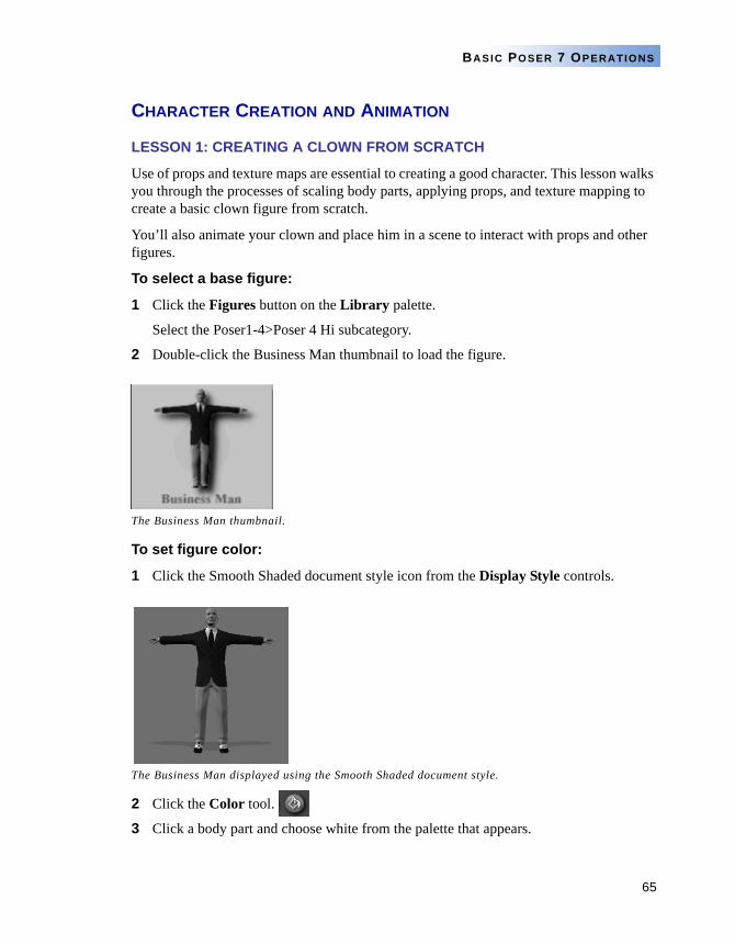
65
BASIC POSER 7 OPERATIONS
CHARACTER CREATION AND ANIMATION
LESSON 1: CREATING A CLOWN FROM SCRATCH
Use of props and texture maps are essential to creating a good character. This lesson walks you through the processes of scaling body parts, applying props, and texture mapping to create a basic clown figure from scratch.
You’ll also animate your clown and place him in a scene to interact with props and other figures.
To select a base figure:
1 Click the Figures button on the Library palette.
Select the Poser1-4>Poser 4 Hi subcategory.
2 Double-click the Business Man thumbnail to load the figure.
To set figure color:
1 Click the Smooth Shaded document style icon from the Display Style controls.
2 Click the Color tool.
3 Click a body part and choose white from the palette that appears.
The Business Man thumbnail.
The Business Man displayed using the Smooth Shaded document style.
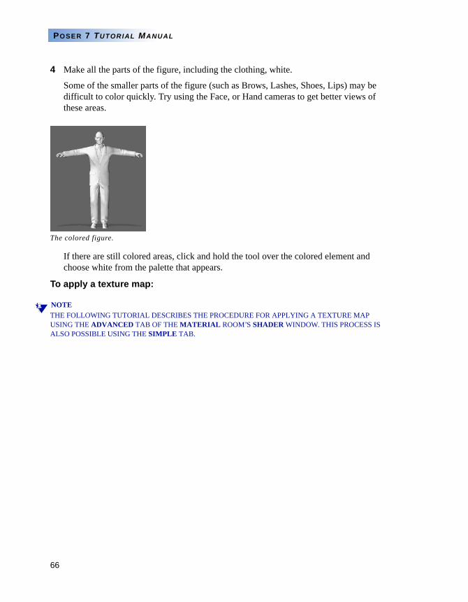
66
POSER 7 TUTORIAL MANUAL
4 Make all the parts of the figure, including the clothing, white.
Some of the smaller parts of the figure (such as Brows, Lashes, Shoes, Lips) may be difficult to color quickly. Try using the Face, or Hand cameras to get better views of these areas.
If there are still colored areas, click and hold the tool over the colored element and choose white from the palette that appears.
To apply a texture map:
NOTETHE FOLLOWING TUTORIAL DESCRIBES THE PROCEDURE FOR APPLYING A TEXTURE MAP USING THE ADVANCED TAB OF THE MATERIAL ROOM’S SHADER WINDOW. THIS PROCESS IS ALSO POSSIBLE USING THE SIMPLE TAB.
The colored figure.
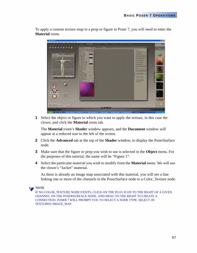
67
BASIC POSER 7 OPERATIONS
To apply a custom texture map to a prop or figure in Poser 7, you will need to enter the Material room.
1 Select the object or figure to which you want to apply the texture, in this case the clown, and click the Material room tab.
The Material room’s Shader window appears, and the Document window will appear at a reduced size to the left of the screen.
2 Click the Advanced tab at the top of the Shader window, to display the PoserSurface node.
3 Make sure that the figure or prop you wish to use is selected in the Object menu. For the purposes of this tutorial, the name will be “Figure 1”.
4 Select the particular material you wish to modify from the Material menu. We will use the clown’s “Jacket” material.
As there is already an image map associated with this material, you will see a line linking one or more of the channels in the PoserSurface node to a Color_Texture node.
NOTEIF NO COLOR_TEXTURE NODE EXISTS, CLICK ON THE PLUG ICON TO THE RIGHT OF A GIVEN CHANNEL ON THE POSERSURFACE NODE, AND DRAG TO THE RIGHT TO CREATE A CONNECTION. POSER 7 WILL PROMPT YOU TO SELECT A NODE TYPE. SELECT 2D TEXTURES>IMAGE_MAP.
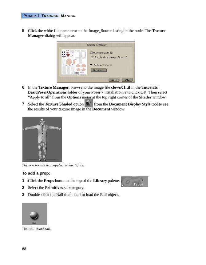
68
POSER 7 TUTORIAL MANUAL
5 Click the white file name next to the Image_Source listing in the node. The Texture Manager dialog will appear.
6 In the Texture Manager, browse to the image file clown01.tif in the Tutorials/BasicPoserOperations folder of your Poser 7 installation, and click OK. Then select “Apply to all” from the Options menu at the top right corner of the Shader window.
7 Select the Texture Shaded option from the Document Display Style tool to see the results of your texture image in the Document window
To add a prop:
1 Click the Props button at the top of the Library palette.
2 Select the Primitives subcategory.
3 Double-click the Ball thumbnail to load the Ball object.
The new texture map applied to the figure.
The Ball thumbnail.
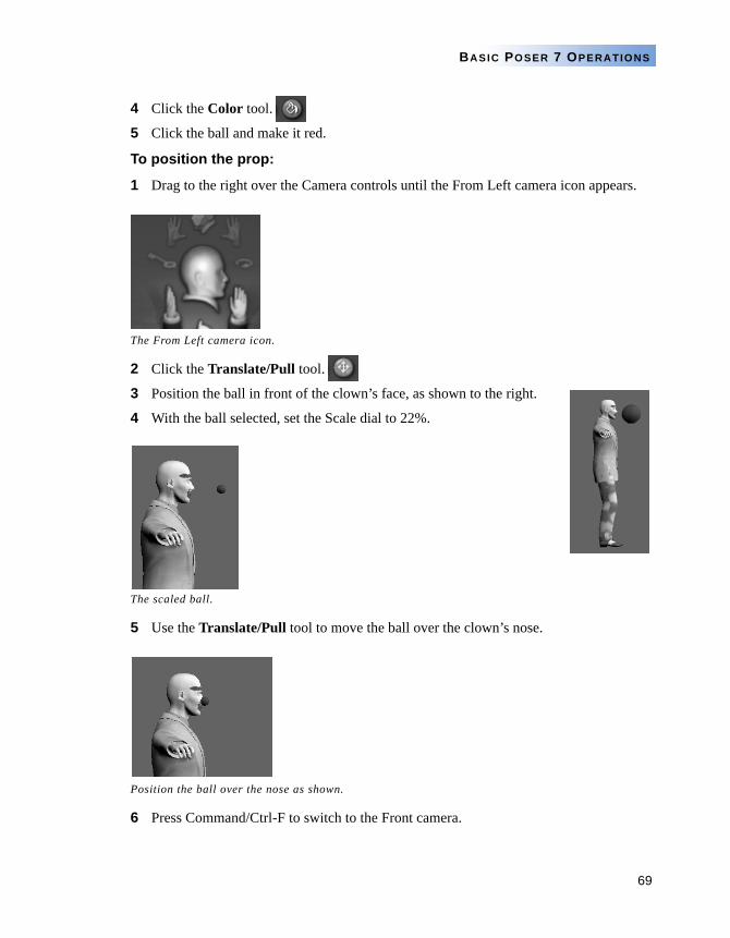
69
BASIC POSER 7 OPERATIONS
4 Click the Color tool.
5 Click the ball and make it red.
To position the prop:
1 Drag to the right over the Camera controls until the From Left camera icon appears.
2 Click the Translate/Pull tool.
3 Position the ball in front of the clown’s face, as shown to the right.
4 With the ball selected, set the Scale dial to 22%.
5 Use the Translate/Pull tool to move the ball over the clown’s nose.
6 Press Command/Ctrl-F to switch to the Front camera.
The From Left camera icon.
The scaled ball.
Position the ball over the nose as shown.
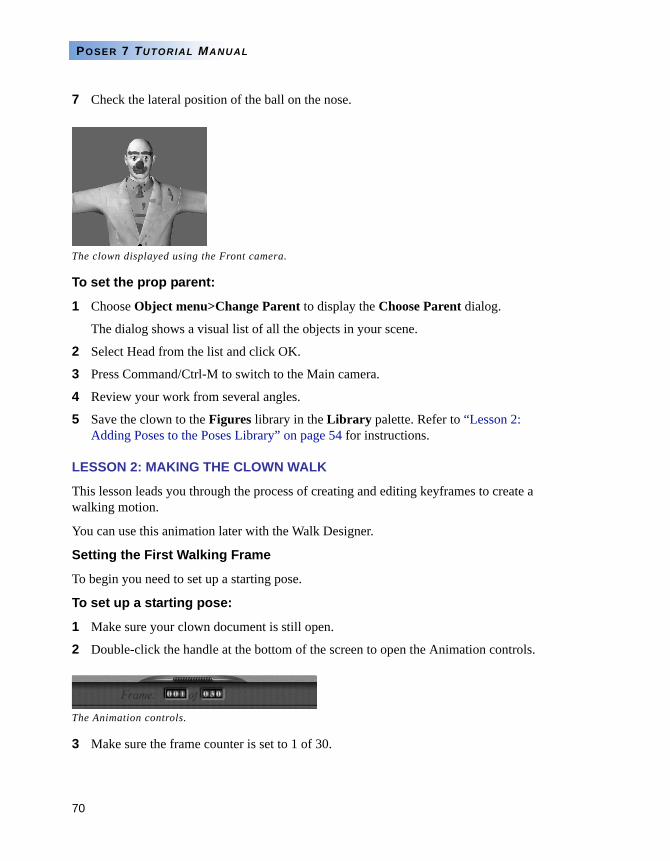
70
POSER 7 TUTORIAL MANUAL
7 Check the lateral position of the ball on the nose.
To set the prop parent:
1 Choose Object menu>Change Parent to display the Choose Parent dialog.
The dialog shows a visual list of all the objects in your scene.
2 Select Head from the list and click OK.
3 Press Command/Ctrl-M to switch to the Main camera.
4 Review your work from several angles.
5 Save the clown to the Figures library in the Library palette. Refer to “Lesson 2: Adding Poses to the Poses Library” on page 54 for instructions.
LESSON 2: MAKING THE CLOWN WALK
This lesson leads you through the process of creating and editing keyframes to create a walking motion.
You can use this animation later with the Walk Designer.
Setting the First Walking Frame
To begin you need to set up a starting pose.
To set up a starting pose:
1 Make sure your clown document is still open.
2 Double-click the handle at the bottom of the screen to open the Animation controls.
3 Make sure the frame counter is set to 1 of 30.
The clown displayed using the Front camera.
The Animation controls.
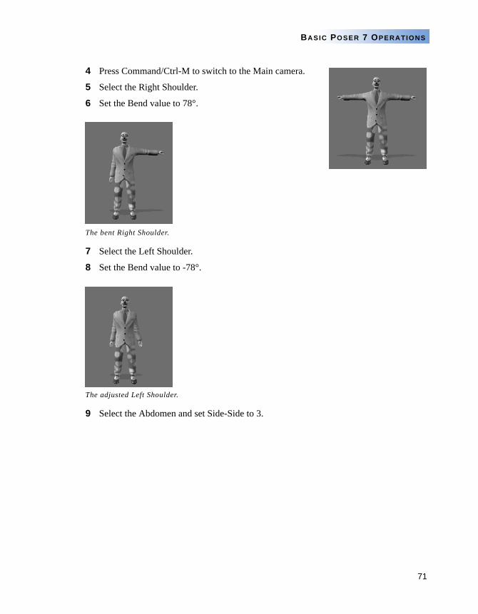
71
BASIC POSER 7 OPERATIONS
4 Press Command/Ctrl-M to switch to the Main camera.
5 Select the Right Shoulder.
6 Set the Bend value to 78°.
7 Select the Left Shoulder.
8 Set the Bend value to -78°.
9 Select the Abdomen and set Side-Side to 3.
The bent Right Shoulder.
The adjusted Left Shoulder.
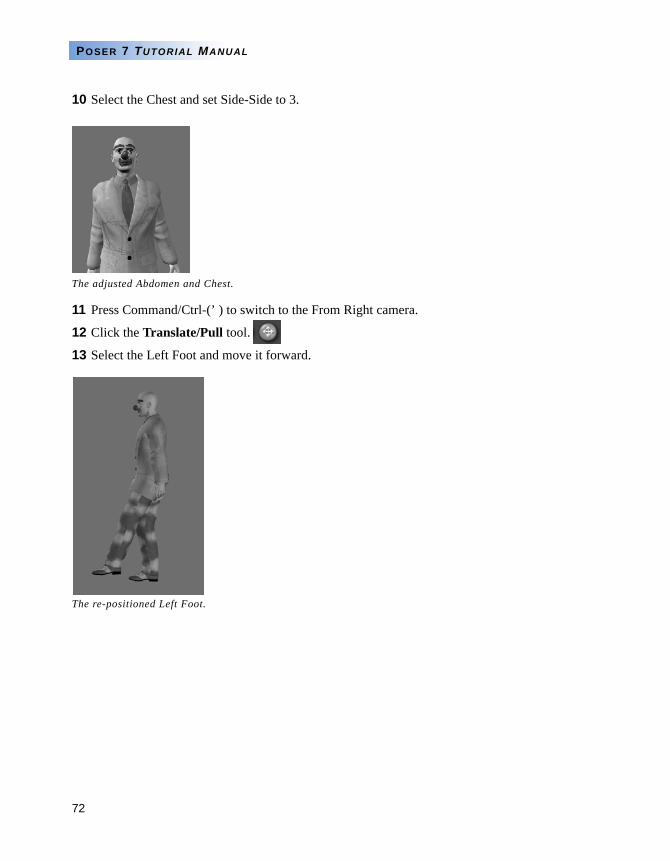
72
POSER 7 TUTORIAL MANUAL
10 Select the Chest and set Side-Side to 3.
11 Press Command/Ctrl-(’ ) to switch to the From Right camera.
12 Click the Translate/Pull tool.
13 Select the Left Foot and move it forward.
The adjusted Abdomen and Chest.
The re-positioned Left Foot.
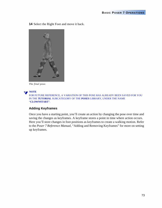
73
BASIC POSER 7 OPERATIONS
14 Select the Right Foot and move it back.
NOTEFOR FUTURE REFERENCE, A VARIATION OF THIS POSE HAS ALREADY BEEN SAVED FOR YOU IN THE TUTORIAL SUBCATEGORY OF THE POSES LIBRARY, UNDER THE NAME “CLOWNSTART”.
Adding Keyframes
Once you have a starting point, you’ll create an action by changing the pose over time and saving the changes as keyframes. A keyframe stores a point in time where action occurs. Here you’ll store changes in foot positions as keyframes to create a walking motion. Refer to the Poser 7 Reference Manual, “Adding and Removing Keyframes” for more on setting up keyframes.
The final pose.
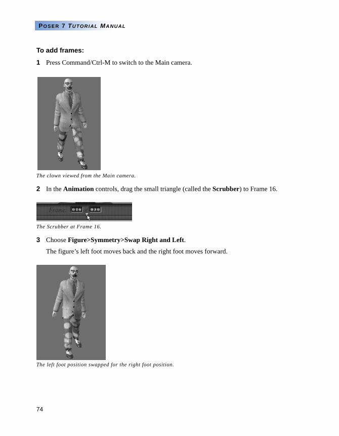
74
POSER 7 TUTORIAL MANUAL
To add frames:
1 Press Command/Ctrl-M to switch to the Main camera.
2 In the Animation controls, drag the small triangle (called the Scrubber) to Frame 16.
3 Choose Figure>Symmetry>Swap Right and Left.
The figure’s left foot moves back and the right foot moves forward.
The clown viewed from the Main camera.
The Scrubber at Frame 16.
The left foot position swapped for the right foot position.
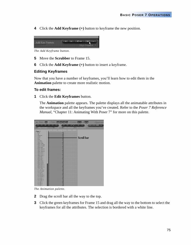
75
BASIC POSER 7 OPERATIONS
4 Click the Add Keyframe (+) button to keyframe the new position.
5 Move the Scrubber to Frame 15.
6 Click the Add Keyframe (+) button to insert a keyframe.
Editing Keyframes
Now that you have a number of keyframes, you’ll learn how to edit them in the Animation palette to create more realistic motion.
To edit frames:
1 Click the Edit Keyframes button.
The Animation palette appears. The palette displays all the animatable attributes in the workspace and all the keyframes you’ve created. Refer to the Poser 7 Reference Manual, “Chapter 11: Animating With Poser 7” for more on this palette.
2 Drag the scroll bar all the way to the top.
3 Click the green keyframes for Frame 15 and drag all the way to the bottom to select the keyframes for all the attributes. The selection is bordered with a white line.
The Add Keyframe button.
The Animation palette.
Scroll bar
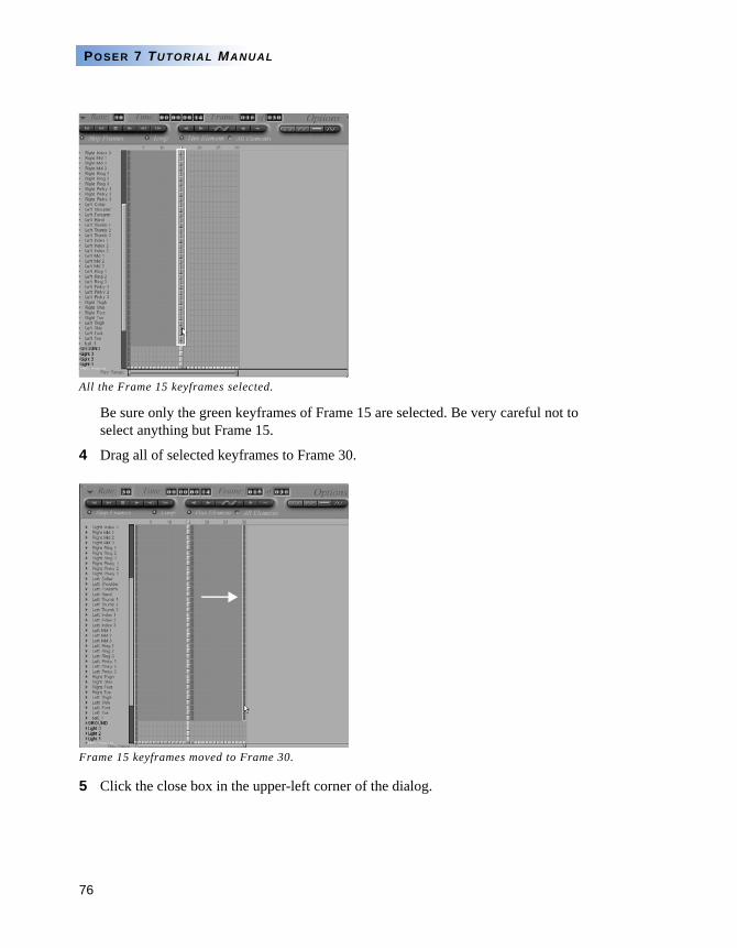
76
POSER 7 TUTORIAL MANUAL
Be sure only the green keyframes of Frame 15 are selected. Be very careful not to select anything but Frame 15.
4 Drag all of selected keyframes to Frame 30.
5 Click the close box in the upper-left corner of the dialog.
All the Frame 15 keyframes selected.
Frame 15 keyframes moved to Frame 30.
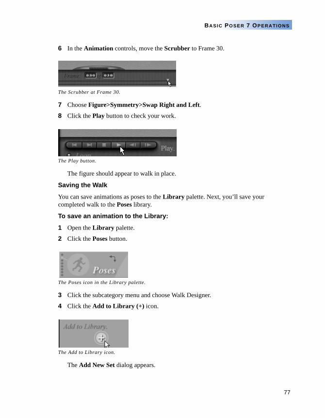
77
BASIC POSER 7 OPERATIONS
6 In the Animation controls, move the Scrubber to Frame 30.
7 Choose Figure>Symmetry>Swap Right and Left.
8 Click the Play button to check your work.
The figure should appear to walk in place.
Saving the Walk
You can save animations as poses to the Library palette. Next, you’ll save your completed walk to the Poses library.
To save an animation to the Library:
1 Open the Library palette.
2 Click the Poses button.
3 Click the subcategory menu and choose Walk Designer.
4 Click the Add to Library (+) icon.
The Add New Set dialog appears.
The Scrubber at Frame 30.
The Play button.
The Poses icon in the Library palette.
The Add to Library icon.
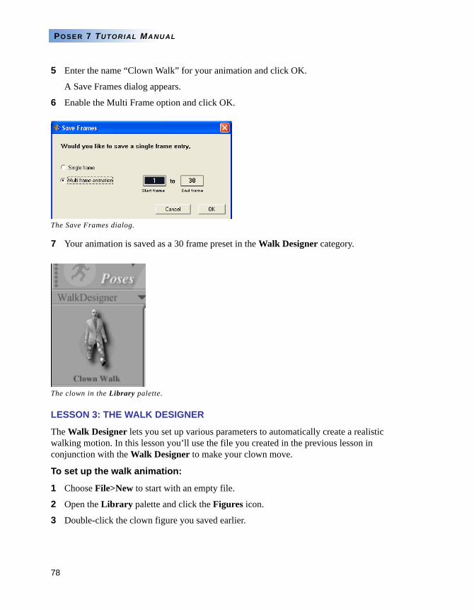
78
POSER 7 TUTORIAL MANUAL
5 Enter the name “Clown Walk” for your animation and click OK.
A Save Frames dialog appears.
6 Enable the Multi Frame option and click OK.
7 Your animation is saved as a 30 frame preset in the Walk Designer category.
LESSON 3: THE WALK DESIGNER
The Walk Designer lets you set up various parameters to automatically create a realistic walking motion. In this lesson you’ll use the file you created in the previous lesson in conjunction with the Walk Designer to make your clown move.
To set up the walk animation:
1 Choose File>New to start with an empty file.
2 Open the Library palette and click the Figures icon.
3 Double-click the clown figure you saved earlier.
The Save Frames dialog.
The clown in the Library palette.
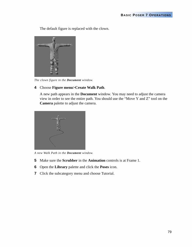
79
BASIC POSER 7 OPERATIONS
The default figure is replaced with the clown.
4 Choose Figure menu>Create Walk Path.
A new path appears in the Document window. You may need to adjust the camera view in order to see the entire path. You should use the “Move Y and Z” tool on the Camera palette to adjust the camera.
5 Make sure the Scrubber in the Animation controls is at Frame 1.
6 Open the Library palette and click the Poses icon.
7 Click the subcategory menu and choose Tutorial.
The clown figure in the Document window.
A new Walk Path in the Document window.
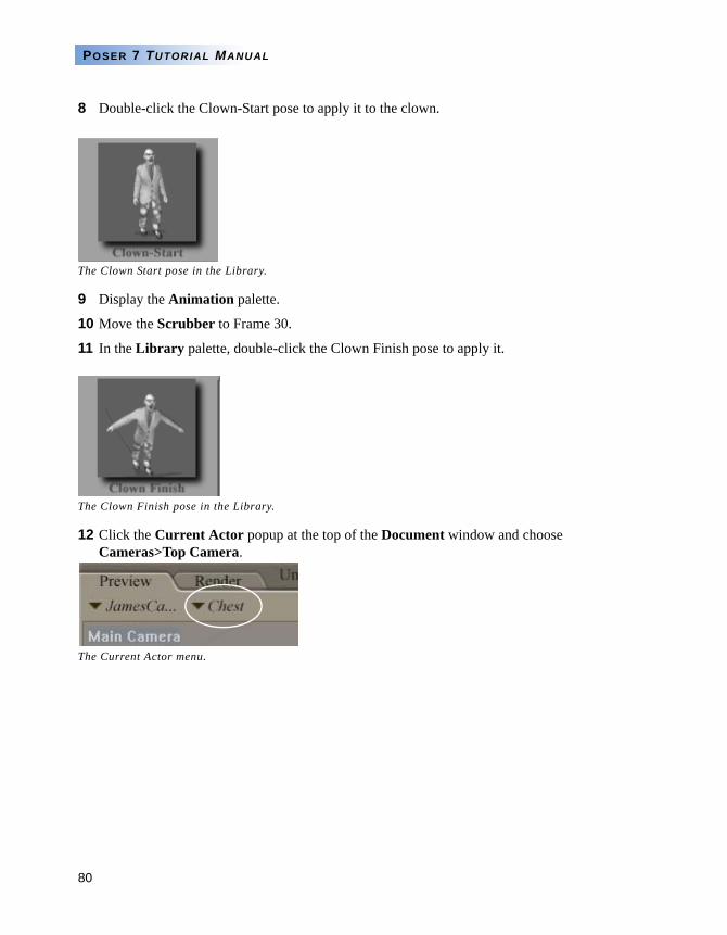
80
POSER 7 TUTORIAL MANUAL
8 Double-click the Clown-Start pose to apply it to the clown.
9 Display the Animation palette.
10 Move the Scrubber to Frame 30.
11 In the Library palette, double-click the Clown Finish pose to apply it.
12 Click the Current Actor popup at the top of the Document window and choose Cameras>Top Camera.
The Clown Start pose in the Library.
The Clown Finish pose in the Library.
The Current Actor menu.
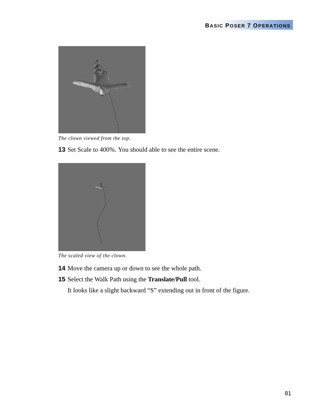
81
BASIC POSER 7 OPERATIONS
13 Set Scale to 400%. You should able to see the entire scene.
14 Move the camera up or down to see the whole path.
15 Select the Walk Path using the Translate/Pull tool.
It looks like a slight backward “S” extending out in front of the figure.
The clown viewed from the top.
The scaled view of the clown.
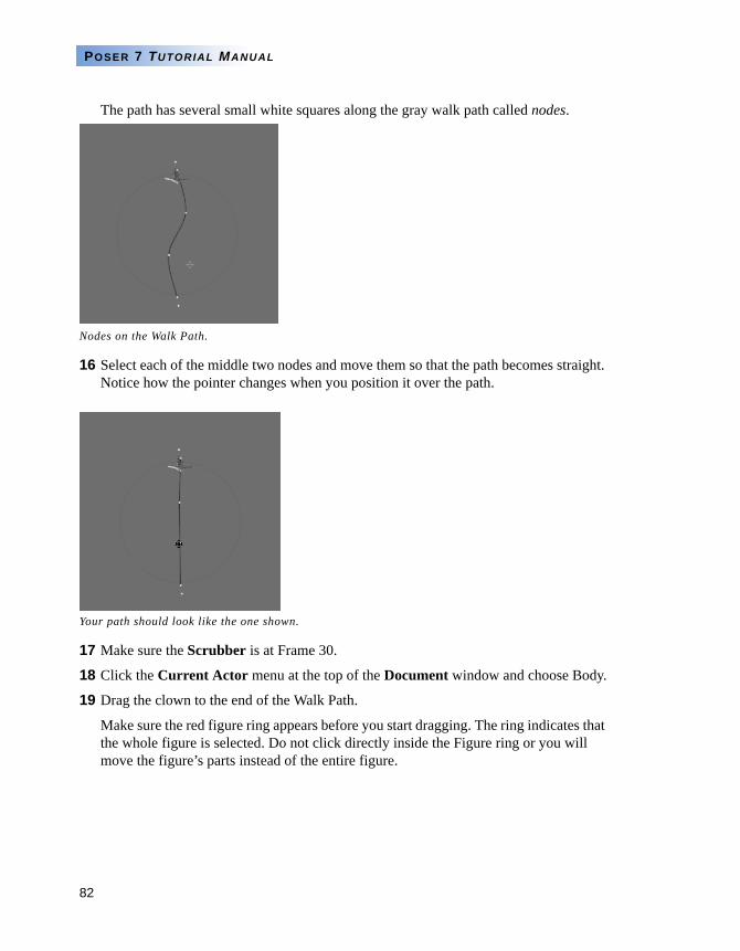
82
POSER 7 TUTORIAL MANUAL
The path has several small white squares along the gray walk path called nodes.
16 Select each of the middle two nodes and move them so that the path becomes straight. Notice how the pointer changes when you position it over the path.
17 Make sure the Scrubber is at Frame 30.
18 Click the Current Actor menu at the top of the Document window and choose Body.
19 Drag the clown to the end of the Walk Path.
Make sure the red figure ring appears before you start dragging. The ring indicates that the whole figure is selected. Do not click directly inside the Figure ring or you will move the figure’s parts instead of the entire figure.
Nodes on the Walk Path.
Your path should look like the one shown.
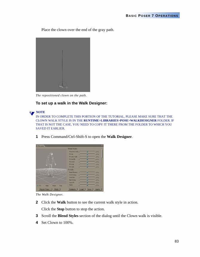
83
BASIC POSER 7 OPERATIONS
Place the clown over the end of the gray path.
To set up a walk in the Walk Designer:
NOTEIN ORDER TO COMPLETE THIS PORTION OF THE TUTORIAL, PLEASE MAKE SURE THAT THE CLOWN WALK STYLE IS IN THE RUNTIME>LIBRARIES>POSE>WALKDESIGNER FOLDER. IF THAT IS NOT THE CASE, YOU NEED TO COPY IT THERE FROM THE FOLDER TO WHICH YOU SAVED IT EARLIER.
1 Press Command/Ctrl-Shift-S to open the Walk Designer.
2 Click the Walk button to see the current walk style in action.
Click the Stop button to stop the action.
3 Scroll the Blend Styles section of the dialog until the Clown walk is visible.
4 Set Clown to 100%.
The repositioned clown on the path.
The Walk Designer.
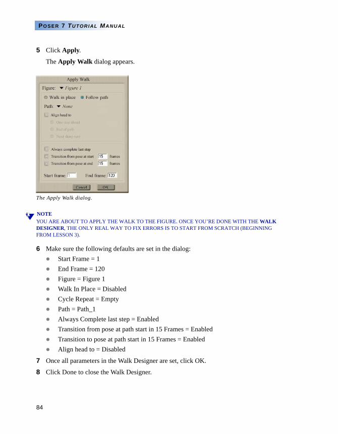
84
POSER 7 TUTORIAL MANUAL
5 Click Apply.
The Apply Walk dialog appears.
NOTEYOU ARE ABOUT TO APPLY THE WALK TO THE FIGURE. ONCE YOU’RE DONE WITH THE WALK DESIGNER, THE ONLY REAL WAY TO FIX ERRORS IS TO START FROM SCRATCH (BEGINNING FROM LESSON 3).
6 Make sure the following defaults are set in the dialog:Start Frame = 1End Frame = 120Figure = Figure 1Walk In Place = DisabledCycle Repeat = EmptyPath = Path_1Always Complete last step = EnabledTransition from pose at path start in 15 Frames = EnabledTransition to pose at path start in 15 Frames = EnabledAlign head to = Disabled
7 Once all parameters in the Walk Designer are set, click OK.
8 Click Done to close the Walk Designer.
The Apply Walk dialog.
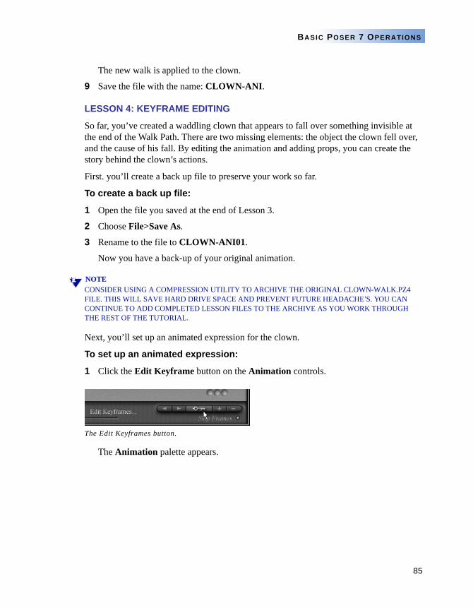
85
BASIC POSER 7 OPERATIONS
The new walk is applied to the clown.
9 Save the file with the name: CLOWN-ANI.
LESSON 4: KEYFRAME EDITING
So far, you’ve created a waddling clown that appears to fall over something invisible at the end of the Walk Path. There are two missing elements: the object the clown fell over, and the cause of his fall. By editing the animation and adding props, you can create the story behind the clown’s actions.
First. you’ll create a back up file to preserve your work so far.
To create a back up file:
1 Open the file you saved at the end of Lesson 3.
2 Choose File>Save As.
3 Rename to the file to CLOWN-ANI01.
Now you have a back-up of your original animation.
NOTECONSIDER USING A COMPRESSION UTILITY TO ARCHIVE THE ORIGINAL CLOWN-WALK.PZ4 FILE. THIS WILL SAVE HARD DRIVE SPACE AND PREVENT FUTURE HEADACHE’S. YOU CAN CONTINUE TO ADD COMPLETED LESSON FILES TO THE ARCHIVE AS YOU WORK THROUGH THE REST OF THE TUTORIAL.
Next, you’ll set up an animated expression for the clown.
To set up an animated expression:
1 Click the Edit Keyframe button on the Animation controls.
The Animation palette appears.
The Edit Keyframes button.
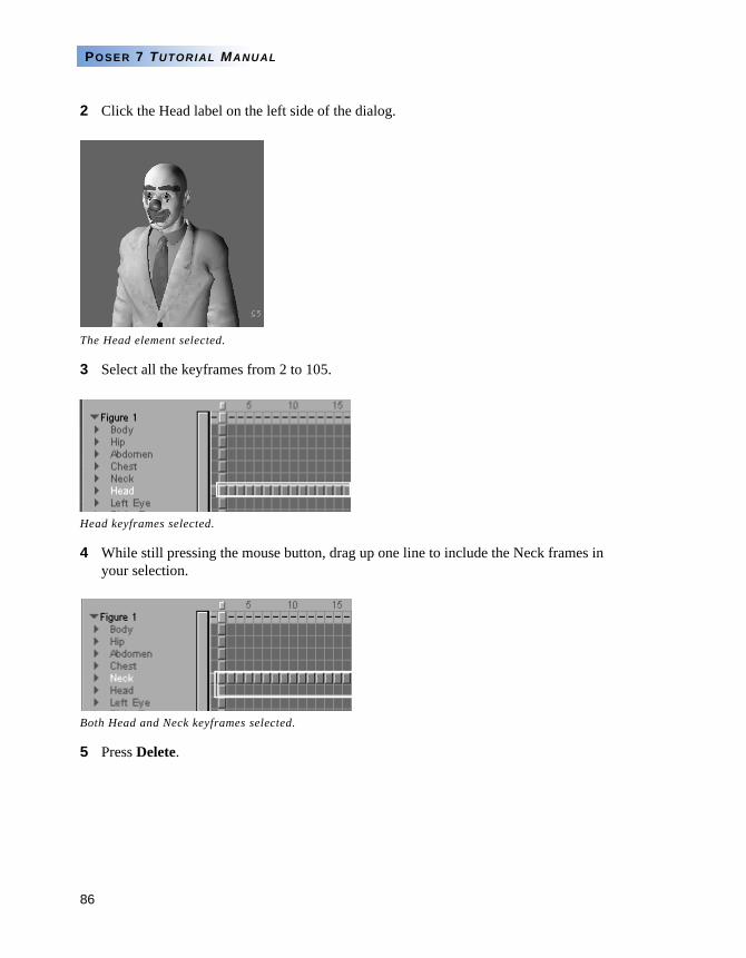
86
POSER 7 TUTORIAL MANUAL
2 Click the Head label on the left side of the dialog.
3 Select all the keyframes from 2 to 105.
4 While still pressing the mouse button, drag up one line to include the Neck frames in your selection.
5 Press Delete.
The Head element selected.
Head keyframes selected.
Both Head and Neck keyframes selected.
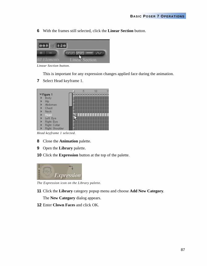
87
BASIC POSER 7 OPERATIONS
6 With the frames still selected, click the Linear Section button.
This is important for any expression changes applied face during the animation.
7 Select Head keyframe 1.
8 Close the Animation palette.
9 Open the Library palette.
10 Click the Expression button at the top of the palette.
11 Click the Library category popup menu and choose Add New Category.
The New Category dialog appears.
12 Enter Clown Faces and click OK.
Linear Section button.
Head keyframe 1 selected.
The Expression icon on the Library palette.
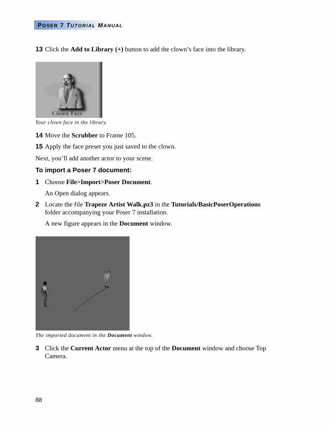
88
POSER 7 TUTORIAL MANUAL
13 Click the Add to Library (+) button to add the clown’s face into the library.
14 Move the Scrubber to Frame 105.
15 Apply the face preset you just saved to the clown.
Next, you’ll add another actor to your scene.
To import a Poser 7 document:
1 Choose File>Import>Poser Document.
An Open dialog appears.
2 Locate the file Trapeze Artist Walk.pz3 in the Tutorials/BasicPoserOperations folder accompanying your Poser 7 installation.
A new figure appears in the Document window.
3 Click the Current Actor menu at the top of the Document window and choose Top Camera.
Your clown face in the library.
The imported document in the Document window.
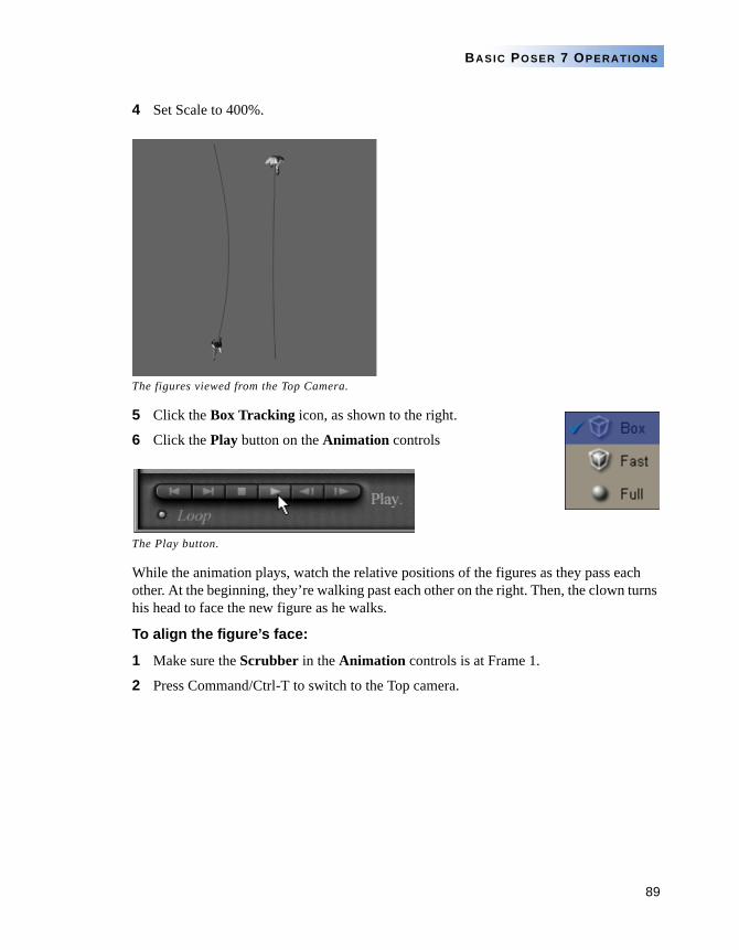
89
BASIC POSER 7 OPERATIONS
4 Set Scale to 400%.
5 Click the Box Tracking icon, as shown to the right.
6 Click the Play button on the Animation controls
While the animation plays, watch the relative positions of the figures as they pass each other. At the beginning, they’re walking past each other on the right. Then, the clown turns his head to face the new figure as he walks.
To align the figure’s face:
1 Make sure the Scrubber in the Animation controls is at Frame 1.
2 Press Command/Ctrl-T to switch to the Top camera.
The figures viewed from the Top Camera.
The Play button.
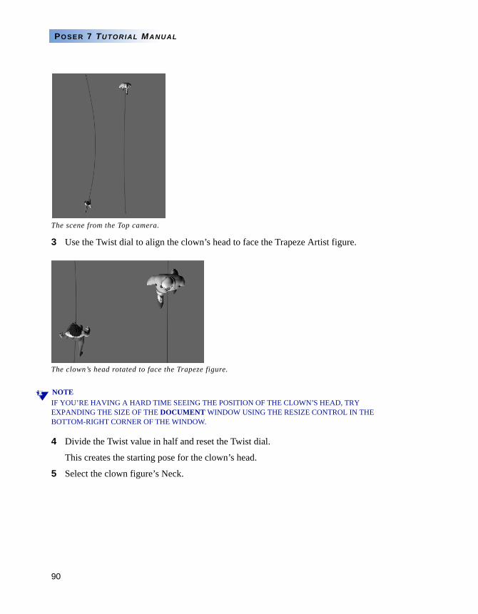
90
POSER 7 TUTORIAL MANUAL
3 Use the Twist dial to align the clown’s head to face the Trapeze Artist figure.
NOTEIF YOU’RE HAVING A HARD TIME SEEING THE POSITION OF THE CLOWN’S HEAD, TRY EXPANDING THE SIZE OF THE DOCUMENT WINDOW USING THE RESIZE CONTROL IN THE BOTTOM-RIGHT CORNER OF THE WINDOW.
4 Divide the Twist value in half and reset the Twist dial.
This creates the starting pose for the clown’s head.
5 Select the clown figure’s Neck.
The scene from the Top camera.
The clown’s head rotated to face the Trapeze figure.
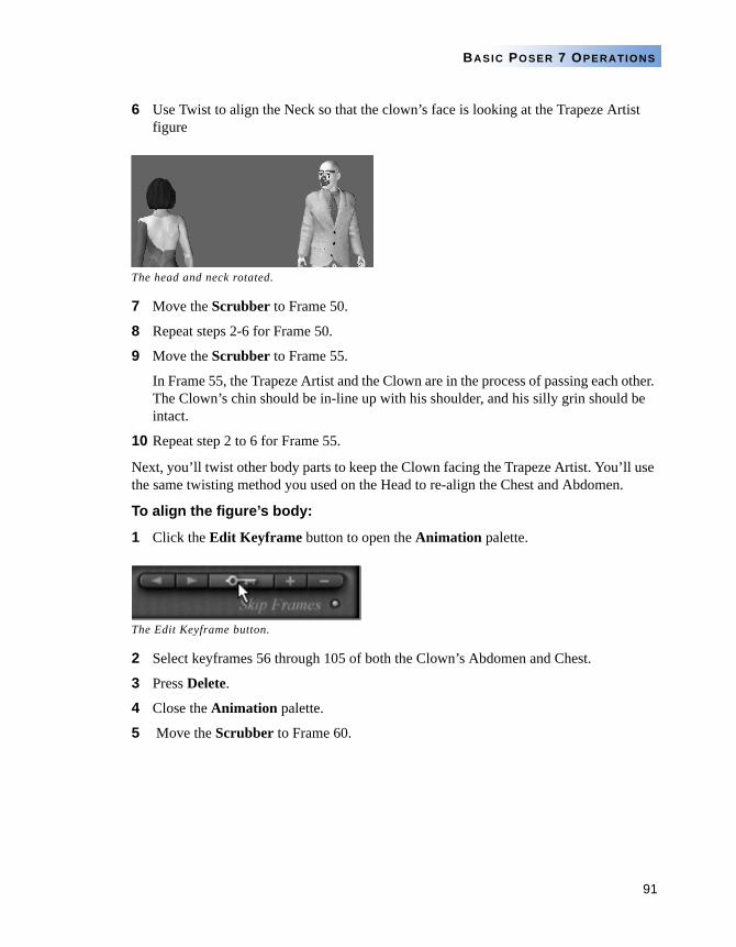
91
BASIC POSER 7 OPERATIONS
6 Use Twist to align the Neck so that the clown’s face is looking at the Trapeze Artist figure
7 Move the Scrubber to Frame 50.
8 Repeat steps 2-6 for Frame 50.
9 Move the Scrubber to Frame 55.
In Frame 55, the Trapeze Artist and the Clown are in the process of passing each other. The Clown’s chin should be in-line up with his shoulder, and his silly grin should be intact.
10 Repeat step 2 to 6 for Frame 55.
Next, you’ll twist other body parts to keep the Clown facing the Trapeze Artist. You’ll use the same twisting method you used on the Head to re-align the Chest and Abdomen.
To align the figure’s body:
1 Click the Edit Keyframe button to open the Animation palette.
2 Select keyframes 56 through 105 of both the Clown’s Abdomen and Chest.
3 Press Delete.
4 Close the Animation palette.
5 Move the Scrubber to Frame 60.
The head and neck rotated.
The Edit Keyframe button.
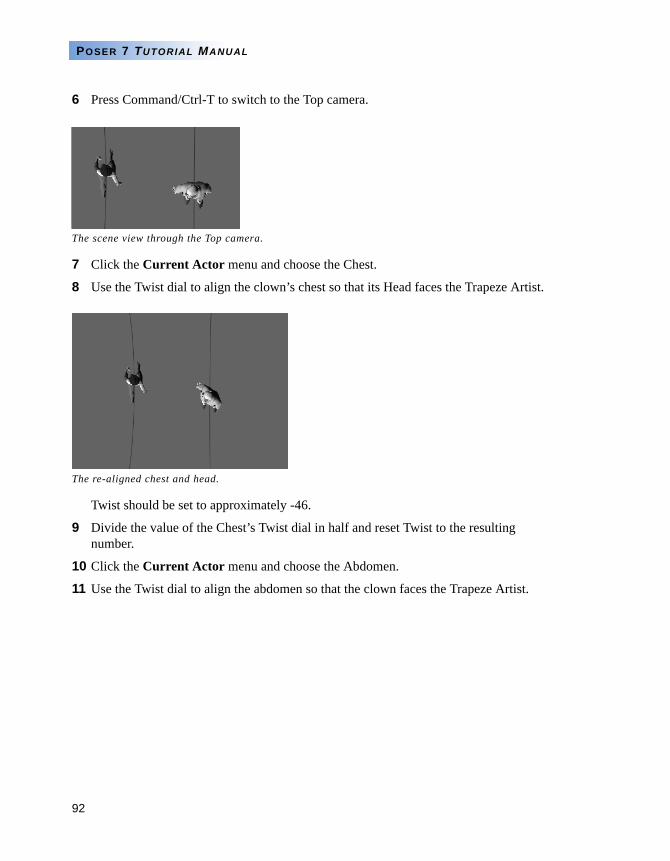
92
POSER 7 TUTORIAL MANUAL
6 Press Command/Ctrl-T to switch to the Top camera.
7 Click the Current Actor menu and choose the Chest.
8 Use the Twist dial to align the clown’s chest so that its Head faces the Trapeze Artist.
Twist should be set to approximately -46.
9 Divide the value of the Chest’s Twist dial in half and reset Twist to the resulting number.
10 Click the Current Actor menu and choose the Abdomen.
11 Use the Twist dial to align the abdomen so that the clown faces the Trapeze Artist.
The scene view through the Top camera.
The re-aligned chest and head.
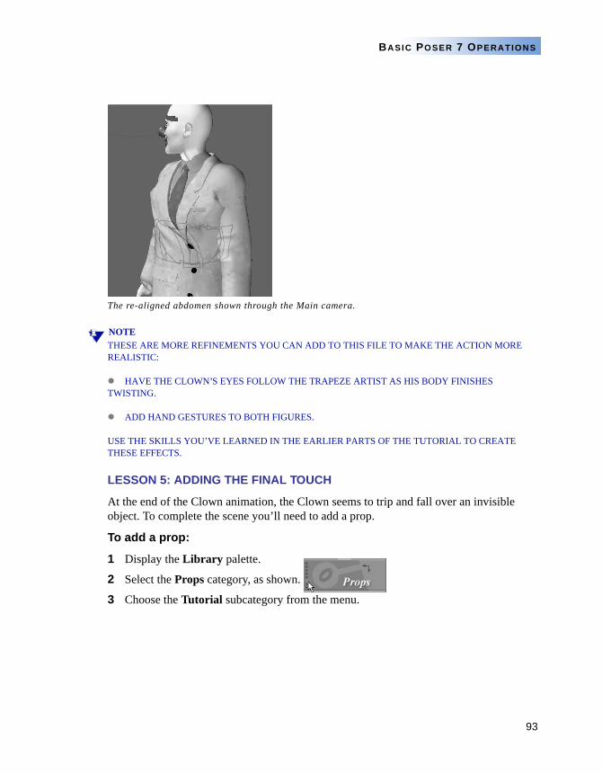
93
BASIC POSER 7 OPERATIONS
NOTETHESE ARE MORE REFINEMENTS YOU CAN ADD TO THIS FILE TO MAKE THE ACTION MORE REALISTIC:
HAVE THE CLOWN’S EYES FOLLOW THE TRAPEZE ARTIST AS HIS BODY FINISHES TWISTING.
ADD HAND GESTURES TO BOTH FIGURES.
USE THE SKILLS YOU’VE LEARNED IN THE EARLIER PARTS OF THE TUTORIAL TO CREATE THESE EFFECTS.
LESSON 5: ADDING THE FINAL TOUCH
At the end of the Clown animation, the Clown seems to trip and fall over an invisible object. To complete the scene you’ll need to add a prop.
To add a prop:
1 Display the Library palette.
2 Select the Props category, as shown.
3 Choose the Tutorial subcategory from the menu.
The re-aligned abdomen shown through the Main camera.
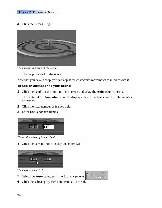
94
POSER 7 TUTORIAL MANUAL
4 Click the Circus Ring.
The prop is added to the scene.
Now that you have a prop, you can adjust the character’s movements to interact with it.
To add an animation to your scene:
1 Click the handle at the bottom of the screen to display the Animation controls.
The center of the Animation controls displays the current frame and the total number of frames.
2 Click the total number of frames field.
3 Enter 130 to add ten frames.
4 Click the current frame display and enter 121.
5 Select the Poses category in the Library palette.
6 Click the subcategory menu and choose Tutorial.
The Circus Ring prop in the scene.
The total number of frames field.
The current frame field.
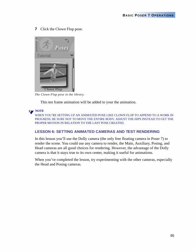
95
BASIC POSER 7 OPERATIONS
7 Click the Clown Flop pose.
This ten frame animation will be added to your the animation.
NOTEWHEN YOU’RE SETTING UP AN ANIMATED POSE LIKE CLOWN FLOP TO APPEND TO A WORK IN PROGRESS, BE SURE NOT TO MOVE THE ENTIRE BODY. ADJUST THE HIPS INSTEAD TO GET THE PROPER MOTION IN RELATION TO THE LAST POSE CREATED.
LESSON 6: SETTING ANIMATED CAMERAS AND TEST RENDERING
In this lesson you’ll use the Dolly camera (the only free floating camera in Poser 7) to render the scene. You could use any camera to render, the Main, Auxiliary, Posing, and Head cameras are all good choices for rendering. However, the advantage of the Dolly camera is that it stays true to its own center, making it useful for animations.
When you’ve completed the lesson, try experimenting with the other cameras, especially the Head and Posing cameras.
The Clown Flop pose in the library.
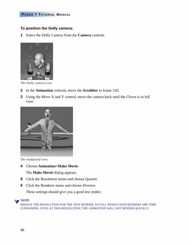
96
POSER 7 TUTORIAL MANUAL
To position the Dolly camera:
1 Select the Dolly Camera from the Camera controls.
2 In the Animation controls, move the Scrubber to frame 120.
3 Using the Move X and Y control, move the camera back until the Clown is in full view.
4 Choose Animation>Make Movie.
The Make Movie dialog appears.
5 Click the Resolution menu and choose Quarter.
6 Click the Renderer menu and choose Preview.
These settings should give you a good test render.
NOTEREDUCE THE RESOLUTION FOR THE TEST RENDER, AS FULL RESOLUTION RENDERS ARE TIME CONSUMING. EVEN AT THIS RESOLUTION, THE ANIMATION WILL NOT RENDER QUICKLY.
The Dolly camera icon.
The readjusted view.
97
BASIC POSER 7 OPERATIONS
7 Click OK. The Save dialog appears.
8 Choose a save location for the QuickTime (MAC) or AVI (PC) file and click OK.
The Video Compression dialog appears.
9 Use the default settings and click OK.
Poser 7 starts rendering.
LESSON 7: FINAL RENDER
After one or more test renders, you’re ready to start the final rendering.
To render your final animation:
1 Choose Render>Render Settings.
2 Select a render engine (FireFly or Poser 4) and adjust the Render Settings as needed.
Enable Shadows and Anti Aliasing to produce the best results.
3 Click Render Now.
Depending on the image size and computer system, the final render may take between 45 minutes to two hours.
Poser 7’s animation toolset is its single most powerful feature. Creating animation is challenging, even for the most experienced user. Patience is key in using all 3D applications, and Poser 7 is no exception.
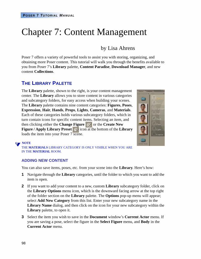
98
POSER 7 TUTORIAL MANUAL
Chapter 7: Content Managementby Lisa Ahrens
Poser 7 offers a variety of powerful tools to assist you with storing, organizing, and obtaining more Poser content. This tutorial will walk you through the benefits available to you from Poser 7’s Library palette, Content Paradise, Download Manager, and new content Collections.
THE LIBRARY PALETTE
The Library palette, shown to the right, is your content management center. The Library allows you to store content in various categories and subcategory folders, for easy access when building your scenes. The Library palette contains nine content categories: Figures, Poses, Expression, Hair, Hands, Props, Lights, Cameras, and Materials. Each of these categories holds various subcategory folders, which in turn contain icons for specific content items. Selecting an item, and then clicking either the Change Figure or the Create New Figure / Apply Library Preset icon at the bottom of the Library loads the item into your Poser 7 scene.
NOTETHE MATERIALS LIBRARY CATEGORY IS ONLY VISIBLE WHEN YOU ARE IN THE MATERIAL ROOM.
ADDING NEW CONTENT
You can also save items, poses, etc. from your scene into the Library. Here’s how:
1 Navigate through the Library categories, until the folder to which you want to add the item is open.
2 If you want to add your content to a new, custom Library subcategory folder, click on the Library Options menu icon, which is the downward facing arrow at the top right of the folder section on the Library palette. The Options pop-up menu will appear; select Add New Category from this list. Enter your new subcategory name in the Library Name dialog, and then click on the icon for your new subcategory within the Library palette, to open it.
3 Select the item you wish to save in the Document window’s Current Actor menu. If you are saving a pose, select the figure in the Select Figure menu, and Body in the Current Actor menu.
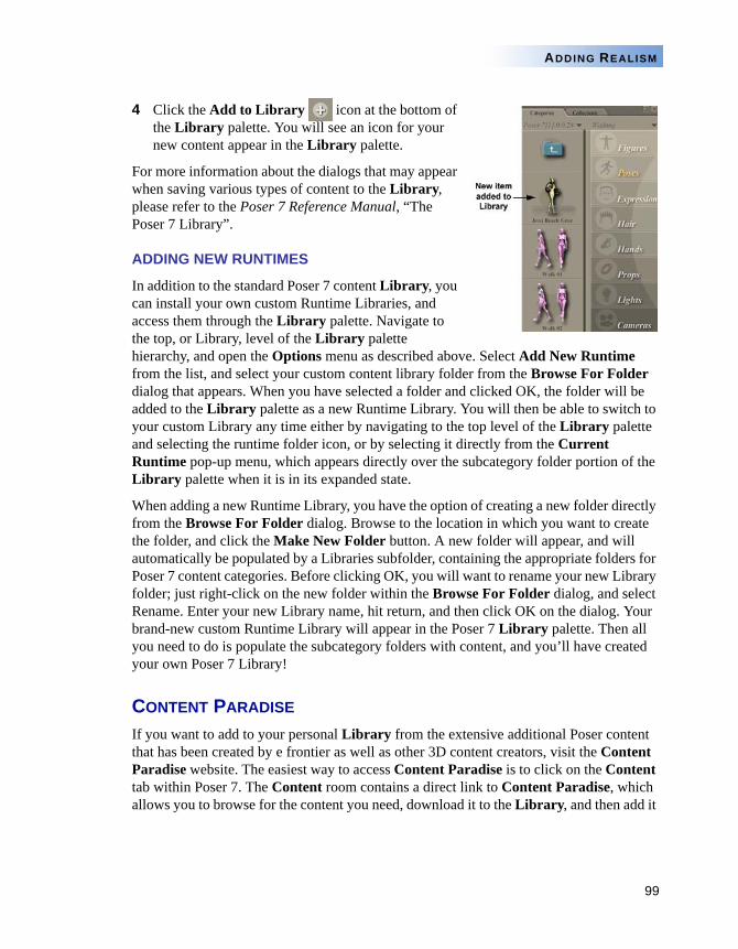
99
ADDING REALISM
4 Click the Add to Library icon at the bottom of the Library palette. You will see an icon for your new content appear in the Library palette.
For more information about the dialogs that may appear when saving various types of content to the Library, please refer to the Poser 7 Reference Manual, “The Poser 7 Library”.
ADDING NEW RUNTIMES
In addition to the standard Poser 7 content Library, you can install your own custom Runtime Libraries, and access them through the Library palette. Navigate to the top, or Library, level of the Library palette hierarchy, and open the Options menu as described above. Select Add New Runtime from the list, and select your custom content library folder from the Browse For Folder dialog that appears. When you have selected a folder and clicked OK, the folder will be added to the Library palette as a new Runtime Library. You will then be able to switch to your custom Library any time either by navigating to the top level of the Library palette and selecting the runtime folder icon, or by selecting it directly from the Current Runtime pop-up menu, which appears directly over the subcategory folder portion of the Library palette when it is in its expanded state.
When adding a new Runtime Library, you have the option of creating a new folder directly from the Browse For Folder dialog. Browse to the location in which you want to create the folder, and click the Make New Folder button. A new folder will appear, and will automatically be populated by a Libraries subfolder, containing the appropriate folders for Poser 7 content categories. Before clicking OK, you will want to rename your new Library folder; just right-click on the new folder within the Browse For Folder dialog, and select Rename. Enter your new Library name, hit return, and then click OK on the dialog. Your brand-new custom Runtime Library will appear in the Poser 7 Library palette. Then all you need to do is populate the subcategory folders with content, and you’ll have created your own Poser 7 Library!
CONTENT PARADISE
If you want to add to your personal Library from the extensive additional Poser content that has been created by e frontier as well as other 3D content creators, visit the Content Paradise website. The easiest way to access Content Paradise is to click on the Content tab within Poser 7. The Content room contains a direct link to Content Paradise, which allows you to browse for the content you need, download it to the Library, and then add it
100
POSER 7 TUTORIAL MANUAL
to your scene, without ever having to leave Poser 7. Alternately, you can visit Content Paradise any time via a standard web browser, at www.contentparadise.com.
When you access Content Paradise from the Content Room, Poser 7’s Download Manager automates the process of downloading and organizing content for you, so you don’t have to interrupt your workflow to figure out correct file placement. Just add the items you want to your shopping cart in Content Paradise, complete the purchase transaction, and download the content files. Download Manager will do the rest--your content will automatically be installed into the appropriate content folders in your Poser 7 Runtime folder, making it accessible from your Library palette.
If for some reason Poser 7 doesn’t recognize the content files you are downloading, you may have to manually add the content to the Poser 7 Runtime folder. See the Poser 7 Reference Manual, “Content Room” and “Appendix B: Poser 7 File Structure” for information about downloading and installing files, and Poser 7 file types and locations. If you wish to read another tutorial that covers manual content installation specifically, please refer to the “Installing New Content Into Poser” tutorial on the e frontier website (www.e-frontier.com), in the Training > Tutorials > Poser > Content Management section.
CONTENT COLLECTIONS
New in Poser 7 is the Library Collections tab. This portion of the Library houses content Collections, which are customized subsets of items from the Library categories. Content Collections can contain items from any category, and from any Runtime Library, which makes scene creation and population really simple. Just navigate once through the Library palette, selecting the items you want to use and adding them to one or more Collections. Then, when you’re ready to put those items into a scene, just click on the Collections tab, open the Collection folder, and voila! All your selected items will be there in one place, ready to go.
For example, say you wanted to create a basic scene of Jessi going to the beach. First, you need to create the content Collection to hold the various content items you will need for the scene. From within any category folder within the Library palette, righ-click on a content item. This opens the Collections menu, which lists all the available content Collections, and includes an option to create new Collections. As we are creating a new
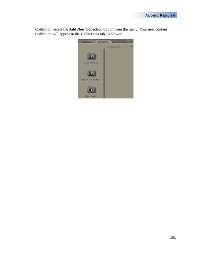
101
ADDING REALISM
Collection, select the Add New Collection option from the menu. Your new content Collection will appear in the Collections tab, as shown:
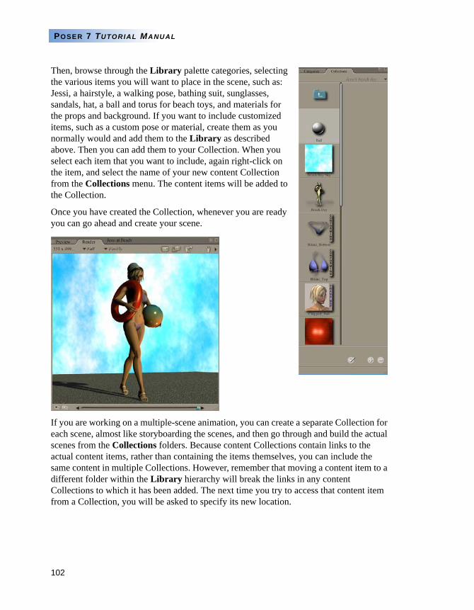
102
POSER 7 TUTORIAL MANUAL
Then, browse through the Library palette categories, selecting the various items you will want to place in the scene, such as: Jessi, a hairstyle, a walking pose, bathing suit, sunglasses, sandals, hat, a ball and torus for beach toys, and materials for the props and background. If you want to include customized items, such as a custom pose or material, create them as you normally would and add them to the Library as described above. Then you can add them to your Collection. When you select each item that you want to include, again right-click on the item, and select the name of your new content Collection from the Collections menu. The content items will be added to the Collection.
Once you have created the Collection, whenever you are ready you can go ahead and create your scene.
If you are working on a multiple-scene animation, you can create a separate Collection for each scene, almost like storyboarding the scenes, and then go through and build the actual scenes from the Collections folders. Because content Collections contain links to the actual content items, rather than containing the items themselves, you can include the same content in multiple Collections. However, remember that moving a content item to a different folder within the Library hierarchy will break the links in any content Collections to which it has been added. The next time you try to access that content item from a Collection, you will be asked to specify its new location.
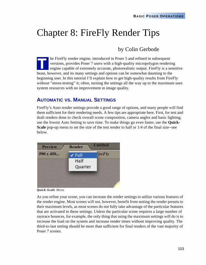
103
BASIC POSER OPERATIONS
Chapter 8: FireFly Render Tipsby Colin Gerbode
he FireFly render engine, introduced in Poser 5 and refined in subsequent versions, provides Poser 7 users with a high-quality micropolygon rendering engine capable of extremely accurate, photorealistic output. FireFly is a sensitive
beast, however, and its many settings and options can be somewhat daunting to the beginning user. In this tutorial I’ll explain how to get high-quality results from FireFly without “stress-testing” it; often, turning the settings all the way up to the maximum uses system resources with no improvement in image quality.
AUTOMATIC VS. MANUAL SETTINGS
FireFly’s Auto render settings provide a good range of options, and many people will find them sufficient for their rendering needs. A few tips are appropriate here. First, for test and draft renders done to check overall scene composition, camera angles and basic lighting, use the lowest Auto Setting to save time. To make things go even faster, use the Quick-Scale pop-up menu to set the size of the test render to half or 1/4 of the final size--see below.
Quick-Scale Menu
As you refine your scene, you can increase the render settings to utilize various features of the render engine. Most scenes will not, however, benefit from setting the render presets to their maximum levels, as most scenes do not fully take advantage of the particular features that are activated in these settings. Unless the particular scene requires a large number of raytrace bounces, for example, the only thing that using the maximum settings will do is to increase the load on the system and increase render times without improving quality. The third-to-last setting should be more than sufficient for final renders of the vast majority of Poser 7 scenes.
T
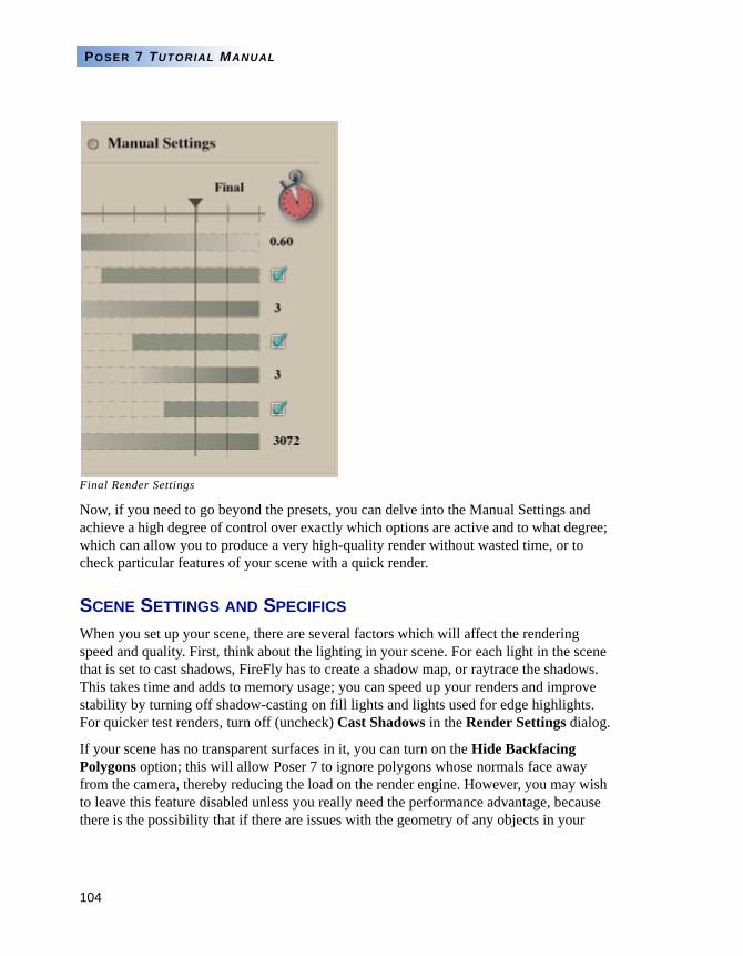
104
POSER 7 TUTORIAL MANUAL
Final Render Settings
Now, if you need to go beyond the presets, you can delve into the Manual Settings and achieve a high degree of control over exactly which options are active and to what degree; which can allow you to produce a very high-quality render without wasted time, or to check particular features of your scene with a quick render.
SCENE SETTINGS AND SPECIFICS
When you set up your scene, there are several factors which will affect the rendering speed and quality. First, think about the lighting in your scene. For each light in the scene that is set to cast shadows, FireFly has to create a shadow map, or raytrace the shadows. This takes time and adds to memory usage; you can speed up your renders and improve stability by turning off shadow-casting on fill lights and lights used for edge highlights. For quicker test renders, turn off (uncheck) Cast Shadows in the Render Settings dialog.
If your scene has no transparent surfaces in it, you can turn on the Hide Backfacing Polygons option; this will allow Poser 7 to ignore polygons whose normals face away from the camera, thereby reducing the load on the render engine. However, you may wish to leave this feature disabled unless you really need the performance advantage, because there is the possibility that if there are issues with the geometry of any objects in your
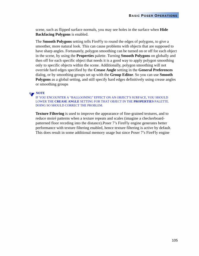
105
BASIC POSER OPERATIONS
scene, such as flipped surface normals, you may see holes in the surface when Hide Backfacing Polygons is enabled.
The Smooth Polygons setting tells FireFly to round the edges of polygons, to give a smoother, more natural look. This can cause problems with objects that are supposed to have sharp angles. Fortunately, polygon smoothing can be turned on or off for each object in the scene, by using the Properties palette. Turning Smooth Polygons on globally and then off for each specific object that needs it is a good way to apply polygon smoothing only to specific objects within the scene. Additionally, polygon smoothing will not override hard edges specified by the Crease Angle setting in the General Preferences dialog, or by smoothing groups set up with the Group Editor. So you can use Smooth Polygons as a global setting, and still specify hard edges definitively using crease angles or smoothing groups
NOTEIF YOU ENCOUNTER A “BALLOONING” EFFECT ON AN OBJECT’S SURFACE, YOU SHOULD LOWER THE CREASE ANGLE SETTING FOR THAT OBJECT IN THE PROPERTIES PALETTE. DOING SO SHOULD CORRECT THE PROBLEM.
Texture Filtering is used to improve the appearance of fine-grained textures, and to reduce moiré patterns when a texture repeats and scales (imagine a checkerboard-patterned floor receding into the distance).Poser 7’s FireFly engine generates better performance with texture filtering enabled, hence texture filtering is active by default. This does result in some additional memory usage but since Poser 7’s FireFly engine
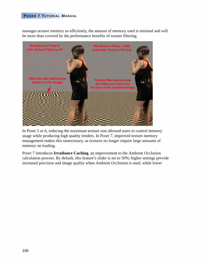
106
POSER 7 TUTORIAL MANUAL
manages texture memory so efficiently, the amount of memory used is minimal and will be more than covered by the performance benefits of texture filtering.
In Poser 5 or 6, reducing the maximum texture size allowed users to control memory usage while producing high quality renders. In Poser 7, improved texture memory management makes this unnecessary, as textures no longer require large amounts of memory on loading.
Poser 7 introduces Irradiance Caching, an improvement to the Ambient Occlusion calculation process. By default, this feature’s slider is set to 50%; higher settings provide increased precision and image quality when Ambient Occlusion is used, while lower
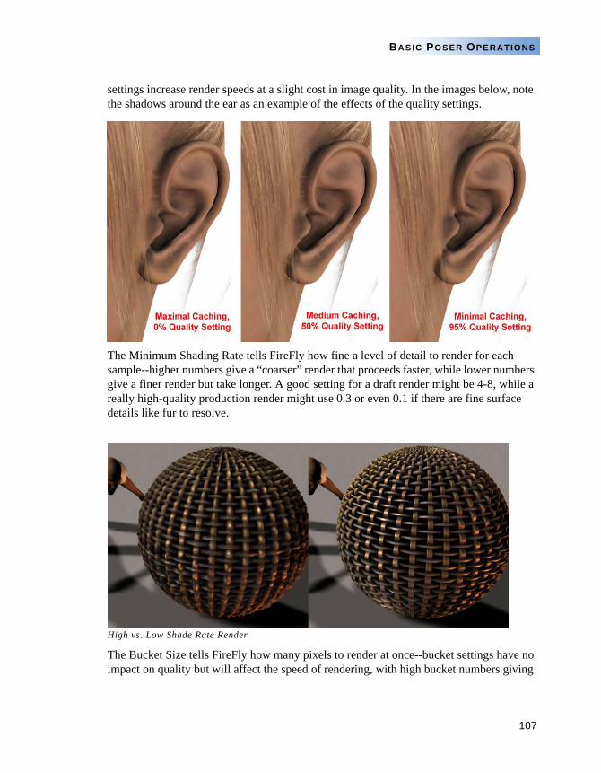
107
BASIC POSER OPERATIONS
settings increase render speeds at a slight cost in image quality. In the images below, note the shadows around the ear as an example of the effects of the quality settings.
The Minimum Shading Rate tells FireFly how fine a level of detail to render for each sample--higher numbers give a “coarser” render that proceeds faster, while lower numbers give a finer render but take longer. A good setting for a draft render might be 4-8, while a really high-quality production render might use 0.3 or even 0.1 if there are fine surface details like fur to resolve.
High vs. Low Shade Rate Render
The Bucket Size tells FireFly how many pixels to render at once--bucket settings have no impact on quality but will affect the speed of rendering, with high bucket numbers giving

108
POSER 7 TUTORIAL MANUAL
faster renders that take more memory and low bucket numbers allowing a render in low memory situations that will take longer. While Minimum Shading Rate trades resources for quality (with an impact on speed), Bucket Size trades resources for speed with no impact on quality.
109
BASIC POSER OPERATIONS
Chapter 9: Creating and Assigning Textures
reating your own textures for figures and/or props requires a solid grasp of the concepts explained in Part 1: “3D Basics” on page 1 and knowledge of one or more 2D graphics tools such as Adobe Photoshop. The process of creating
textures is very similar if not identical for many 3D applications. While it’s impossible to cover the entire process in this book, we can give you enough information to understand the basics and begin creating your own maps.
NOTE THIS SECTION COVERS CREATING MAPS. PLEASE REFER TO THE POSER 7 REFERENCE MANUAL, “PART 4: MATERIALS” FOR INFORMATION ABOUT APPLYING MAPS TO SHADERS.
CREATING TEXTURE TEMPLATES
If you use the figures and props that came with Poser 7 (or if you buy figures from most third-party vendors), they probably come with one or more ready-made texture maps and one or more blank templates. If you need to create a new texture template, you’ll need to follow a process that is roughly similar to the following:
1 Create your mesh object in your preferred 3D modeling application.
2 Export the mesh in a format supported by Poser 7 (see the Poser 7 Reference Manual, “Importing 3D Objects” for a list of supported formats).
3 If your 3D modeling application supports exporting your mesh object with UV mapping data, be sure to do this, as this will probably create your template for you. Please refer to your 3D modeling application documentation for information.
4 If your exported object does not have UV information, you’ll need to use an application such as UV Mapper (http://www.uvmapper.com) to create the UV information and a blank template that can be used for any sort of map (texture, bump, transparency, reflection, displacement, etc.). If you use a third-party application to create texture templates, please refer to that application’s documentation for information on using that application. Also, should you require technical support, please contact the application’s creator or vendor. e frontier cannot provide support for third-party applications.
C
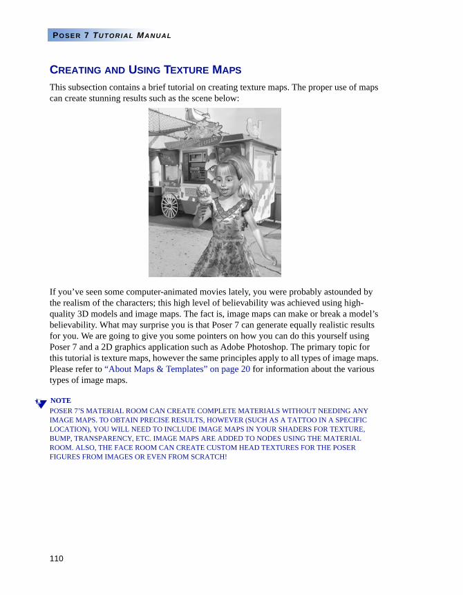
110
POSER 7 TUTORIAL MANUAL
CREATING AND USING TEXTURE MAPS
This subsection contains a brief tutorial on creating texture maps. The proper use of maps can create stunning results such as the scene below:
If you’ve seen some computer-animated movies lately, you were probably astounded by the realism of the characters; this high level of believability was achieved using high-quality 3D models and image maps. The fact is, image maps can make or break a model’s believability. What may surprise you is that Poser 7 can generate equally realistic results for you. We are going to give you some pointers on how you can do this yourself using Poser 7 and a 2D graphics application such as Adobe Photoshop. The primary topic for this tutorial is texture maps, however the same principles apply to all types of image maps. Please refer to “About Maps & Templates” on page 20 for information about the various types of image maps.
NOTEPOSER 7’S MATERIAL ROOM CAN CREATE COMPLETE MATERIALS WITHOUT NEEDING ANY IMAGE MAPS. TO OBTAIN PRECISE RESULTS, HOWEVER (SUCH AS A TATTOO IN A SPECIFIC LOCATION), YOU WILL NEED TO INCLUDE IMAGE MAPS IN YOUR SHADERS FOR TEXTURE, BUMP, TRANSPARENCY, ETC. IMAGE MAPS ARE ADDED TO NODES USING THE MATERIAL ROOM. ALSO, THE FACE ROOM CAN CREATE CUSTOM HEAD TEXTURES FOR THE POSER FIGURES FROM IMAGES OR EVEN FROM SCRATCH!
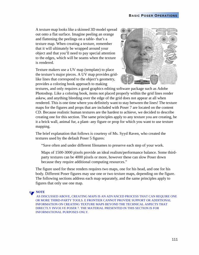
111
BASIC POSER OPERATIONS
A texture map looks like a skinned 3D model spread out onto a flat surface. Imagine peeling an orange and flattening the peelings on a table- that’s a texture map. When creating a texture, remember that it will ultimately be wrapped around your object and that you’ll need to pay special attention to the edges, which will be seams when the texture is rendered.
Texture makers use a UV map (template) to place the texture’s major pieces. A UV map provides grid-like lines that correspond to the object’s geometry, provides a coloring book approach to making textures, and only requires a good graphics editing software package such as Adobe Photoshop. Like a coloring book, items not placed properly within the grid lines render askew, and anything bleeding over the edge of the grid does not appear at all when rendered. This is one time where you definitely want to stay between the lines! The texture maps for the figures and props that are included with Poser 7 are located on the content CD. Because realistic human textures are the hardest to achieve, we decided to describe creating one for this section. The same principles apply to any texture you are creating, be it a brick wall, animal fur, a plant- any figure or prop for which you want to use texture mapping.
The brief explanation that follows is courtesy of Ms. Syyd Raven, who created the textures used by the default Poser 5 figures:
“Save often and under different filenames to preserve each step of your work.
Maps of 1500-3000 pixels provide an ideal realism/performance balance. Some third-party textures can be 4000 pixels or more, however these can slow Poser down because they require additional computing resources.”
The figure used for these renders requires two maps, one for his head, and one for his body. Different Poser figures may use one or two texture maps, depending on the figure. The following sections address each map separately, and the same principles apply to figures that only use one map.
NOTE AS DISCUSSED ABOVE, CREATING MAPS IS AN ADVANCED PROCESS THAT CAN REQUIRE ONE OR MORE THIRD-PARTY TOOLS. E FRONTIER CANNOT PROVIDE SUPPORT OR ADDITIONAL INFORMATION ON CREATING TEXTURE MAPS BEYOND THE TECHNICAL ASPECTS THAT DIRECTLY INVOLVE POSER 7. THE MATERIAL PRESENTED IN THIS SECTION IS FOR INFORMATIONAL PURPOSES ONLY.
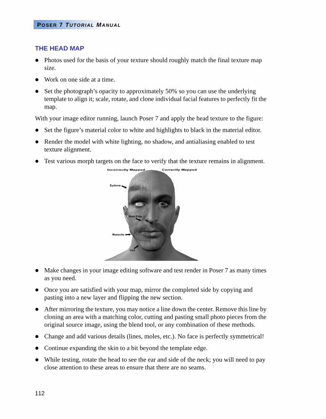
112
POSER 7 TUTORIAL MANUAL
THE HEAD MAP
Photos used for the basis of your texture should roughly match the final texture map size.
Work on one side at a time.
Set the photograph’s opacity to approximately 50% so you can use the underlying template to align it; scale, rotate, and clone individual facial features to perfectly fit the map.
With your image editor running, launch Poser 7 and apply the head texture to the figure:
Set the figure’s material color to white and highlights to black in the material editor.
Render the model with white lighting, no shadow, and antialiasing enabled to test texture alignment.
Test various morph targets on the face to verify that the texture remains in alignment.
Make changes in your image editing software and test render in Poser 7 as many times as you need.
Once you are satisfied with your map, mirror the completed side by copying and pasting into a new layer and flipping the new section.
After mirroring the texture, you may notice a line down the center. Remove this line by cloning an area with a matching color, cutting and pasting small photo pieces from the original source image, using the blend tool, or any combination of these methods.
Change and add various details (lines, moles, etc.). No face is perfectly symmetrical!
Continue expanding the skin to a bit beyond the template edge.
While testing, rotate the head to see the ear and side of the neck; you will need to pay close attention to these areas to ensure that there are no seams.
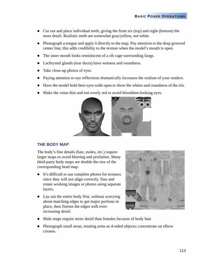
113
BASIC POSER OPERATIONS
Cut out and place individual teeth, giving the front six (top) and eight (bottom) the most detail. Realistic teeth are somewhat gray/yellow, not white.
Photograph a tongue and apply it directly to the map. Pay attention to the deep grooved center line; this adds credibility to the texture when the model’s mouth is open.
The inner mouth looks reminiscent of a rib cage surrounding lungs.
Lachrymal glands (tear ducts) have wetness and roundness.
Take close-up photos of eyes.
Paying attention to eye reflections dramatically increases the realism of your renders.
Have the model hold their eyes wide open to show the whites and roundness of the iris.
Make the veins thin and not overly red to avoid bloodshot-looking eyes.
THE BODY MAP
The body’s fine details (hair, moles, etc.) require larger maps to avoid blurring and pixilation. Many third-party body maps are double the size of the corresponding head map.
It’s difficult to use complete photos for textures since they will not align correctly. Size and rotate working images or photos using separate layers.
Lay out the entire body first, without worrying about matching edges to get major portions in place, then finesse the edges with ever-increasing detail.
Male maps require more detail than females because of body hair.
Photograph small areas, treating arms as 4-sided objects; concentrate on elbow creases.
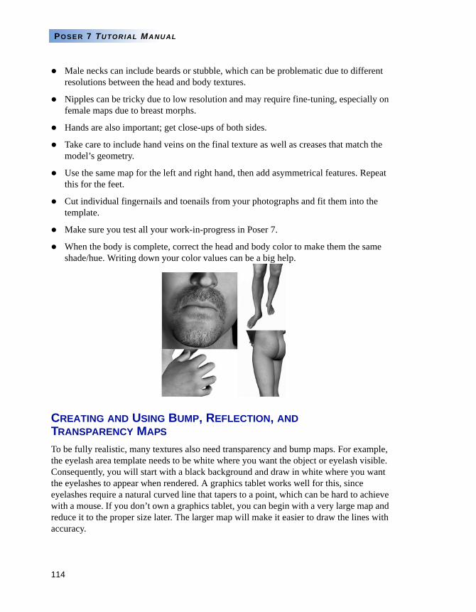
114
POSER 7 TUTORIAL MANUAL
Male necks can include beards or stubble, which can be problematic due to different resolutions between the head and body textures.
Nipples can be tricky due to low resolution and may require fine-tuning, especially on female maps due to breast morphs.
Hands are also important; get close-ups of both sides.
Take care to include hand veins on the final texture as well as creases that match the model’s geometry.
Use the same map for the left and right hand, then add asymmetrical features. Repeat this for the feet.
Cut individual fingernails and toenails from your photographs and fit them into the template.
Make sure you test all your work-in-progress in Poser 7.
When the body is complete, correct the head and body color to make them the same shade/hue. Writing down your color values can be a big help.
CREATING AND USING BUMP, REFLECTION, AND TRANSPARENCY MAPS
To be fully realistic, many textures also need transparency and bump maps. For example, the eyelash area template needs to be white where you want the object or eyelash visible. Consequently, you will start with a black background and draw in white where you want the eyelashes to appear when rendered. A graphics tablet works well for this, since eyelashes require a natural curved line that tapers to a point, which can be hard to achieve with a mouse. If you don’t own a graphics tablet, you can begin with a very large map and reduce it to the proper size later. The larger map will make it easier to draw the lines with accuracy.
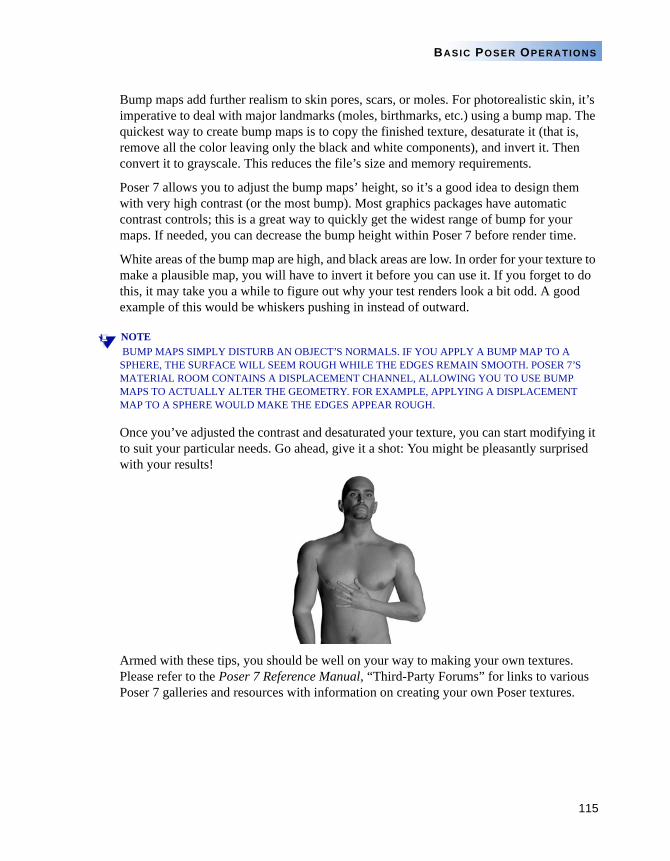
115
BASIC POSER OPERATIONS
Bump maps add further realism to skin pores, scars, or moles. For photorealistic skin, it’s imperative to deal with major landmarks (moles, birthmarks, etc.) using a bump map. The quickest way to create bump maps is to copy the finished texture, desaturate it (that is, remove all the color leaving only the black and white components), and invert it. Then convert it to grayscale. This reduces the file’s size and memory requirements.
Poser 7 allows you to adjust the bump maps’ height, so it’s a good idea to design them with very high contrast (or the most bump). Most graphics packages have automatic contrast controls; this is a great way to quickly get the widest range of bump for your maps. If needed, you can decrease the bump height within Poser 7 before render time.
White areas of the bump map are high, and black areas are low. In order for your texture to make a plausible map, you will have to invert it before you can use it. If you forget to do this, it may take you a while to figure out why your test renders look a bit odd. A good example of this would be whiskers pushing in instead of outward.
NOTE BUMP MAPS SIMPLY DISTURB AN OBJECT’S NORMALS. IF YOU APPLY A BUMP MAP TO A SPHERE, THE SURFACE WILL SEEM ROUGH WHILE THE EDGES REMAIN SMOOTH. POSER 7’S MATERIAL ROOM CONTAINS A DISPLACEMENT CHANNEL, ALLOWING YOU TO USE BUMP MAPS TO ACTUALLY ALTER THE GEOMETRY. FOR EXAMPLE, APPLYING A DISPLACEMENT MAP TO A SPHERE WOULD MAKE THE EDGES APPEAR ROUGH.
Once you’ve adjusted the contrast and desaturated your texture, you can start modifying it to suit your particular needs. Go ahead, give it a shot: You might be pleasantly surprised with your results!
Armed with these tips, you should be well on your way to making your own textures. Please refer to the Poser 7 Reference Manual, “Third-Party Forums” for links to various Poser 7 galleries and resources with information on creating your own Poser textures.
PART 3
Adding Realism
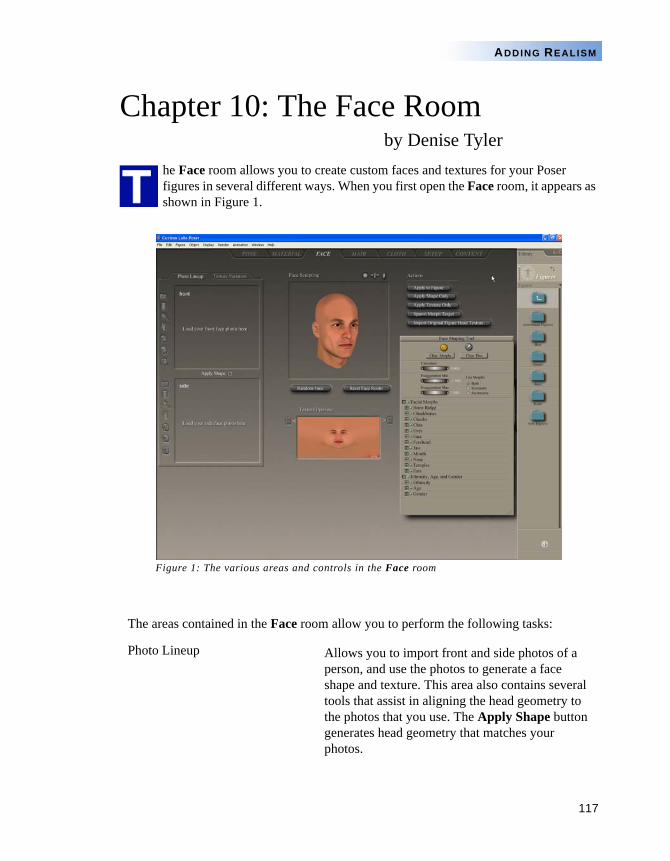
117
ADDING REALISM
Chapter 10: The Face Roomby Denise Tyler
he Face room allows you to create custom faces and textures for your Poser figures in several different ways. When you first open the Face room, it appears as shown in Figure 1.
Figure 1: The various areas and controls in the Face room
The areas contained in the Face room allow you to perform the following tasks:
Photo Lineup Allows you to import front and side photos of a person, and use the photos to generate a face shape and texture. This area also contains several tools that assist in aligning the head geometry to the photos that you use. The Apply Shape button generates head geometry that matches your photos.
T
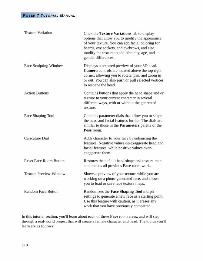
118
POSER 7 TUTORIAL MANUAL
In this tutorial section, you'll learn about each of these Face room areas, and will step through a real-world project that will create a female character and head. The topics you'll learn are as follows:
Texture Variation Click the Texture Variations tab to display options that allow you to modify the appearance of your texture. You can add facial coloring for beards, eye sockets, and eyebrows, and also modify the texture to add ethnicity, age, and gender differences.
Face Sculpting Window Displays a textured preview of your 3D head. Camera controls are located above the top right corner, allowing you to rotate, pan, and zoom in or out. You can also push or pull selected vertices to reshape the head.
Action Buttons Contains buttons that apply the head shape and or texture to your current character in several different ways, with or without the generated texture.
Face Shaping Tool Contains parameter dials that allow you to shape the head and facial features further. The dials are similar to those in the Parameters palette of the Pose room.
Caricature Dial Adds character to your face by enhancing the features. Negative values de-exaggerate head and facial features, while positive values over-exaggerate them.
Reset Face Room Button Restores the default head shape and texture map and undoes all previous Face room work.
Texture Preview Window Shows a preview of your texture while you are working on a photo-generated face, and allows you to load or save face texture maps.
Random Face Button Randomizes the Face Shaping Tool morph settings to generate a new face as a starting point. Use this feature with caution, as it erases any work that you have previously completed.
119
ADDING REALISM
Getting Ready for Your Face Room Project
Choosing and Preparing Photos
Task 1: Import the Photos to the Face Room
Task 2: Adjust Size, Position, and Rotation
Task 3: Adjust Feature Points
Task 4: Refine the Head Shape
Task 5: Apply to Your Figure
GETTING READY FOR YOUR FACE ROOM PROJECT
Though their heads are shaped and sized a bit differently, Don, Judy, Will, and Penny have one thing in common. They all share the same head geometry. As a result, the Face room morphs work on all of them. It has to do with the face geometry.
In order for any figure to work in the Face room, it must use the same head geometry that Don, Judy, Will and Penny use - otherwise, the morphs will be incompatible. Seeing as the main reason for the Face room is to create customized characters, the morphs are vital to this process. Unfortunately, this means that there are many other Poser figures that will not be compatible with the Face room, because their head geometry is entirely different.
So, go to the Pose room and load Don, Judy, Will, or Penny onto the stage. When you do this is not really important, but you'll definitely want to make sure you have the right character there before you apply your custom head to the figure. For the purpose of this tutorial, add Judy in the Pose room as shown in Figure 2. If you're creating a male texture instead, choose Don.
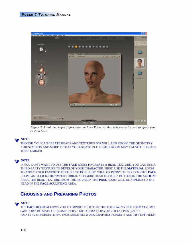
120
POSER 7 TUTORIAL MANUAL
Figure 2: Load the proper figure into the Pose Room, so that it is ready for you to apply your custom head.
NOTETHOUGH YOU CAN CREATE HEADS AND TEXTURES FOR WILL AND PENNY, THE GEOMETRY ADJUSTMENTS AND MORPHS THAT YOU CREATE IN THE FACE ROOM MAY CAUSE THE HEADS TO BE LARGER.
NOTEIF YOU DON'T WANT TO USE THE FACE ROOM TO CREATE A HEAD TEXTURE, YOU CAN USE A THIRD-PARTY TEXTURE TO DEVELOP YOUR CHARACTER. FIRST, USE THE MATERIAL ROOM TO APPLY YOUR FAVORITE TEXTURE TO DON, JUDY, WILL, OR PENNY. THEN GO TO THE FACE ROOM, AND CLICK THE "IMPORT ORIGINAL FIGURE HEAD TEXTURE" BUTTON IN THE ACTIONS AREA. THE HEAD TEXTURE FROM THE FIGURE IN THE POSE ROOM WILL BE APPLIED TO THE HEAD IN THE FACE SCULPTING AREA.
CHOOSING AND PREPARING PHOTOS
NOTETHE FACE ROOM ALLOWS YOU TO IMPORT PHOTOS IN THE FOLLOWING FILE FORMATS: BMP (WINDOWS BITMAP); GIF (COMPUSERVE GIF FORMAT); JPG (JPG FILES); PCX (ZSOFT PAINTBRUSH FORMAT); PNG (PORTABLE NETWORK GRAPHICS FORMAT) AND TIF (TIFF FILES)
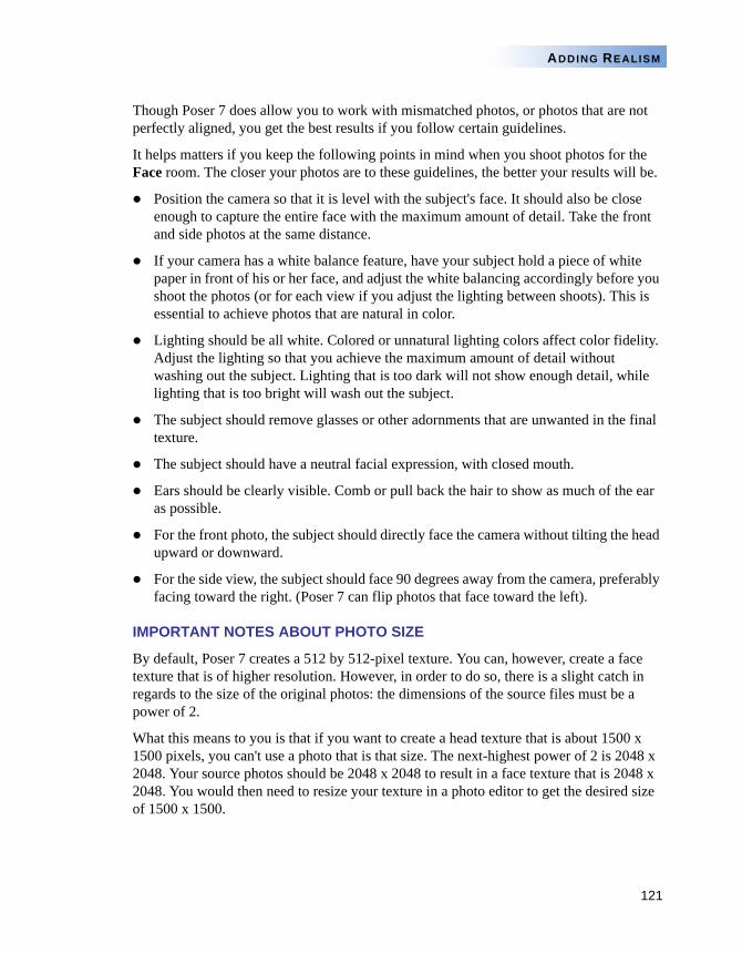
121
ADDING REALISM
Though Poser 7 does allow you to work with mismatched photos, or photos that are not perfectly aligned, you get the best results if you follow certain guidelines.
It helps matters if you keep the following points in mind when you shoot photos for the Face room. The closer your photos are to these guidelines, the better your results will be.
Position the camera so that it is level with the subject's face. It should also be close enough to capture the entire face with the maximum amount of detail. Take the front and side photos at the same distance.
If your camera has a white balance feature, have your subject hold a piece of white paper in front of his or her face, and adjust the white balancing accordingly before you shoot the photos (or for each view if you adjust the lighting between shoots). This is essential to achieve photos that are natural in color.
Lighting should be all white. Colored or unnatural lighting colors affect color fidelity. Adjust the lighting so that you achieve the maximum amount of detail without washing out the subject. Lighting that is too dark will not show enough detail, while lighting that is too bright will wash out the subject.
The subject should remove glasses or other adornments that are unwanted in the final texture.
The subject should have a neutral facial expression, with closed mouth.
Ears should be clearly visible. Comb or pull back the hair to show as much of the ear as possible.
For the front photo, the subject should directly face the camera without tilting the head upward or downward.
For the side view, the subject should face 90 degrees away from the camera, preferably facing toward the right. (Poser 7 can flip photos that face toward the left).
IMPORTANT NOTES ABOUT PHOTO SIZE
By default, Poser 7 creates a 512 by 512-pixel texture. You can, however, create a face texture that is of higher resolution. However, in order to do so, there is a slight catch in regards to the size of the original photos: the dimensions of the source files must be a power of 2.
What this means to you is that if you want to create a head texture that is about 1500 x 1500 pixels, you can't use a photo that is that size. The next-highest power of 2 is 2048 x 2048. Your source photos should be 2048 x 2048 to result in a face texture that is 2048 x 2048. You would then need to resize your texture in a photo editor to get the desired size of 1500 x 1500.
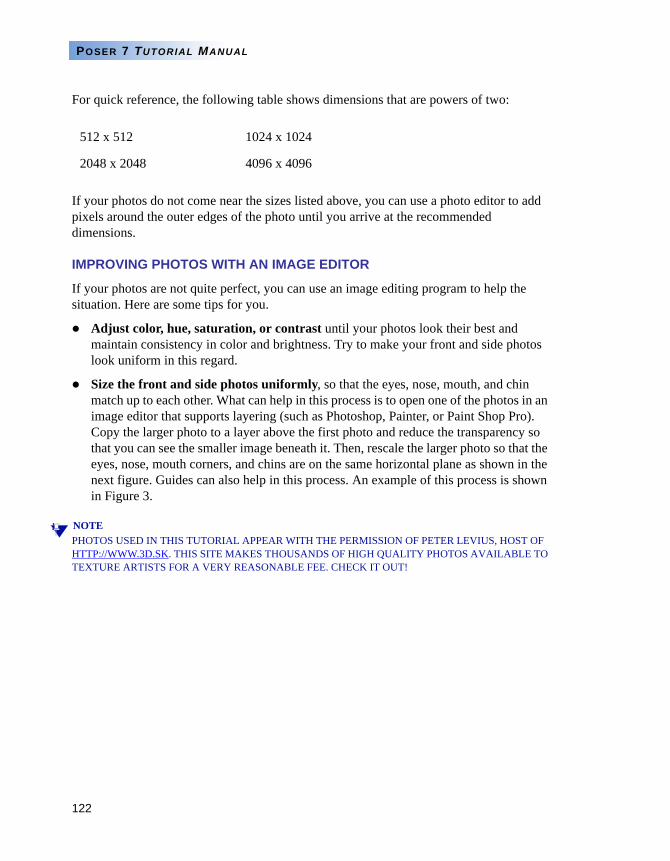
122
POSER 7 TUTORIAL MANUAL
For quick reference, the following table shows dimensions that are powers of two:
If your photos do not come near the sizes listed above, you can use a photo editor to add pixels around the outer edges of the photo until you arrive at the recommended dimensions.
IMPROVING PHOTOS WITH AN IMAGE EDITOR
If your photos are not quite perfect, you can use an image editing program to help the situation. Here are some tips for you.
Adjust color, hue, saturation, or contrast until your photos look their best and maintain consistency in color and brightness. Try to make your front and side photos look uniform in this regard.
Size the front and side photos uniformly, so that the eyes, nose, mouth, and chin match up to each other. What can help in this process is to open one of the photos in an image editor that supports layering (such as Photoshop, Painter, or Paint Shop Pro). Copy the larger photo to a layer above the first photo and reduce the transparency so that you can see the smaller image beneath it. Then, rescale the larger photo so that the eyes, nose, mouth corners, and chins are on the same horizontal plane as shown in the next figure. Guides can also help in this process. An example of this process is shown in Figure 3.
NOTEPHOTOS USED IN THIS TUTORIAL APPEAR WITH THE PERMISSION OF PETER LEVIUS, HOST OF HTTP://WWW.3D.SK. THIS SITE MAKES THOUSANDS OF HIGH QUALITY PHOTOS AVAILABLE TO TEXTURE ARTISTS FOR A VERY REASONABLE FEE. CHECK IT OUT!
512 x 512 1024 x 1024
2048 x 2048 4096 x 4096
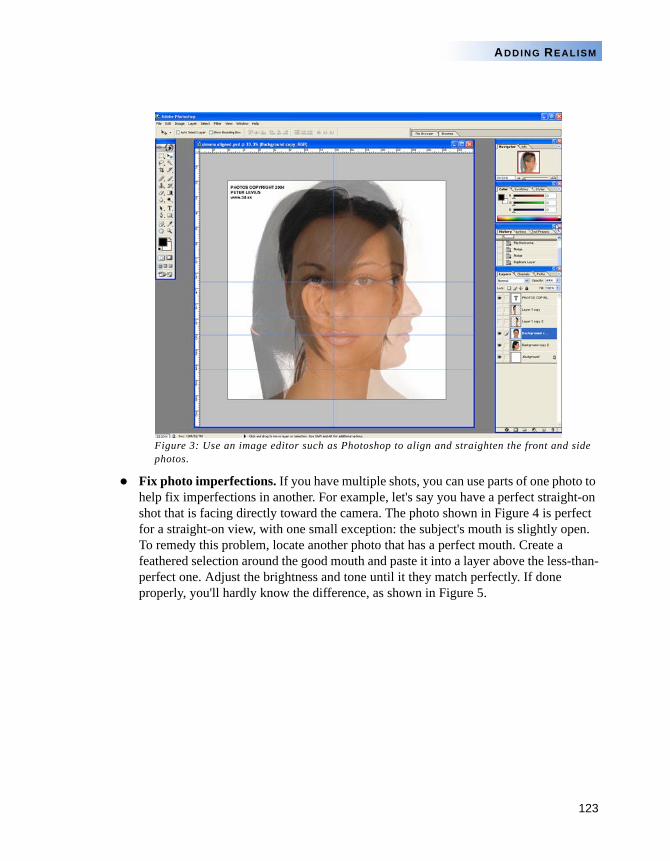
123
ADDING REALISM
Figure 3: Use an image editor such as Photoshop to align and straighten the front and side photos.
Fix photo imperfections. If you have multiple shots, you can use parts of one photo to help fix imperfections in another. For example, let's say you have a perfect straight-on shot that is facing directly toward the camera. The photo shown in Figure 4 is perfect for a straight-on view, with one small exception: the subject's mouth is slightly open. To remedy this problem, locate another photo that has a perfect mouth. Create a feathered selection around the good mouth and paste it into a layer above the less-than-perfect one. Adjust the brightness and tone until it they match perfectly. If done properly, you'll hardly know the difference, as shown in Figure 5.
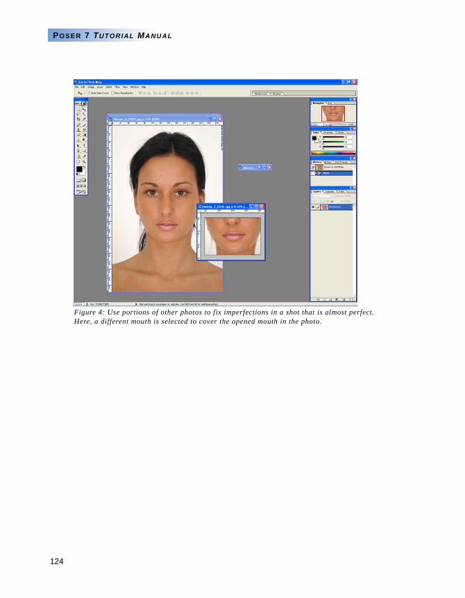
124
POSER 7 TUTORIAL MANUAL
Figure 4: Use portions of other photos to fix imperfections in a shot that is almost perfect. Here, a different mouth is selected to cover the opened mouth in the photo.
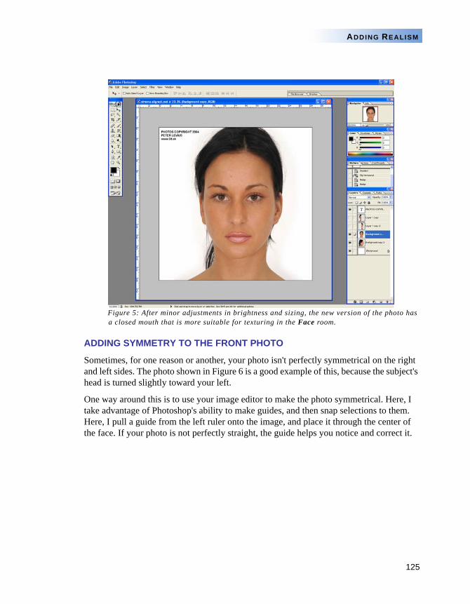
125
ADDING REALISM
Figure 5: After minor adjustments in brightness and sizing, the new version of the photo has a closed mouth that is more suitable for texturing in the Face room.
ADDING SYMMETRY TO THE FRONT PHOTO
Sometimes, for one reason or another, your photo isn't perfectly symmetrical on the right and left sides. The photo shown in Figure 6 is a good example of this, because the subject's head is turned slightly toward your left.
One way around this is to use your image editor to make the photo symmetrical. Here, I take advantage of Photoshop's ability to make guides, and then snap selections to them. Here, I pull a guide from the left ruler onto the image, and place it through the center of the face. If your photo is not perfectly straight, the guide helps you notice and correct it.
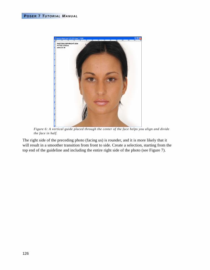
126
POSER 7 TUTORIAL MANUAL
Figure 6: A vertical guide placed through the center of the face helps you align and divide the face in half.
The right side of the preceding photo (facing us) is rounder, and it is more likely that it will result in a smoother transition from front to side. Create a selection, starting from the top end of the guideline and including the entire right side of the photo (see Figure 7).
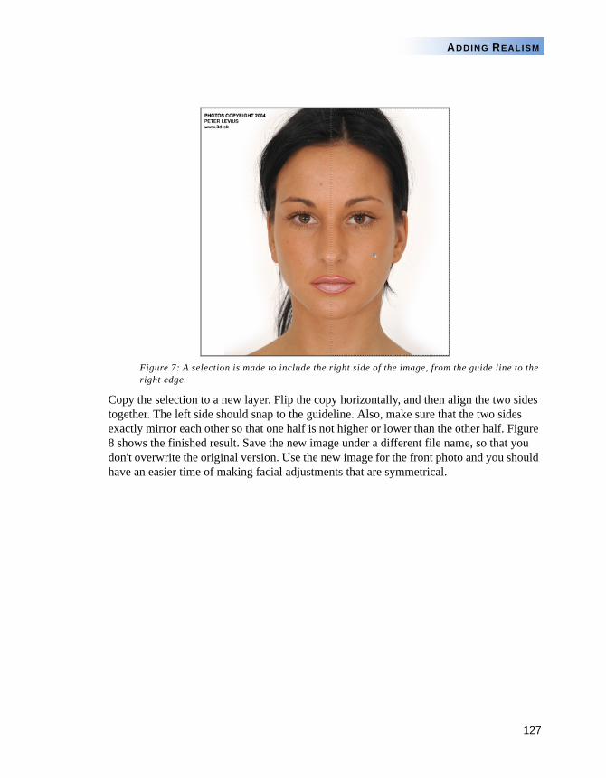
127
ADDING REALISM
Figure 7: A selection is made to include the right side of the image, from the guide line to the right edge.
Copy the selection to a new layer. Flip the copy horizontally, and then align the two sides together. The left side should snap to the guideline. Also, make sure that the two sides exactly mirror each other so that one half is not higher or lower than the other half. Figure 8 shows the finished result. Save the new image under a different file name, so that you don't overwrite the original version. Use the new image for the front photo and you should have an easier time of making facial adjustments that are symmetrical.
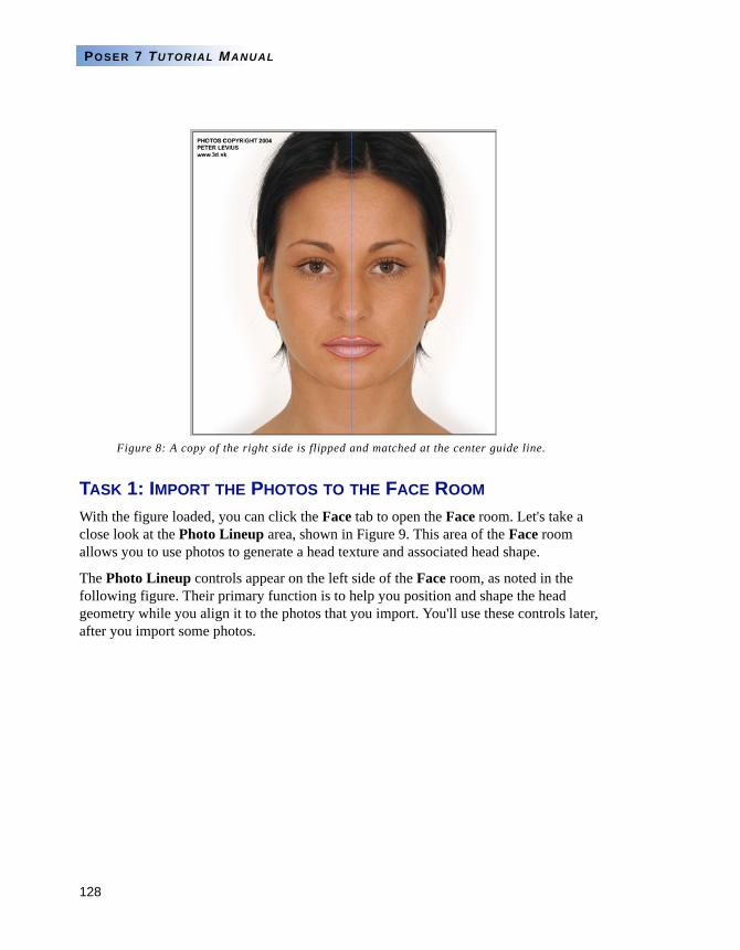
128
POSER 7 TUTORIAL MANUAL
Figure 8: A copy of the right side is flipped and matched at the center guide line.
TASK 1: IMPORT THE PHOTOS TO THE FACE ROOM
With the figure loaded, you can click the Face tab to open the Face room. Let's take a close look at the Photo Lineup area, shown in Figure 9. This area of the Face room allows you to use photos to generate a head texture and associated head shape.
The Photo Lineup controls appear on the left side of the Face room, as noted in the following figure. Their primary function is to help you position and shape the head geometry while you align it to the photos that you import. You'll use these controls later, after you import some photos.
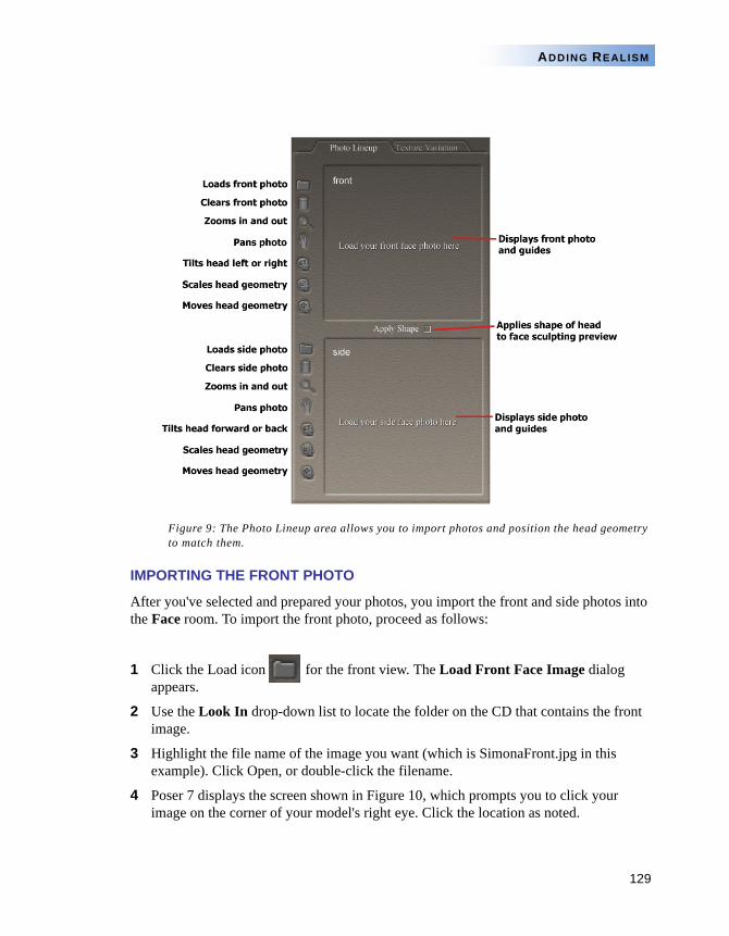
129
ADDING REALISM
Figure 9: The Photo Lineup area allows you to import photos and position the head geometry to match them.
IMPORTING THE FRONT PHOTO
After you've selected and prepared your photos, you import the front and side photos into the Face room. To import the front photo, proceed as follows:
1 Click the Load icon for the front view. The Load Front Face Image dialog appears.
2 Use the Look In drop-down list to locate the folder on the CD that contains the front image.
3 Highlight the file name of the image you want (which is SimonaFront.jpg in this example). Click Open, or double-click the filename.
4 Poser 7 displays the screen shown in Figure 10, which prompts you to click your image on the corner of your model's right eye. Click the location as noted.
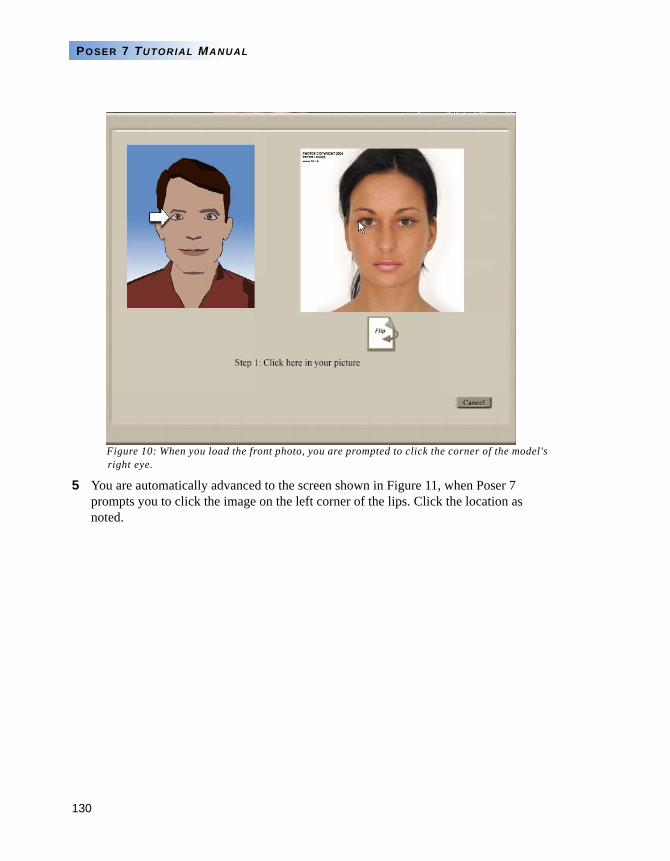
130
POSER 7 TUTORIAL MANUAL
Figure 10: When you load the front photo, you are prompted to click the corner of the model's right eye.
5 You are automatically advanced to the screen shown in Figure 11, when Poser 7 prompts you to click the image on the left corner of the lips. Click the location as noted.
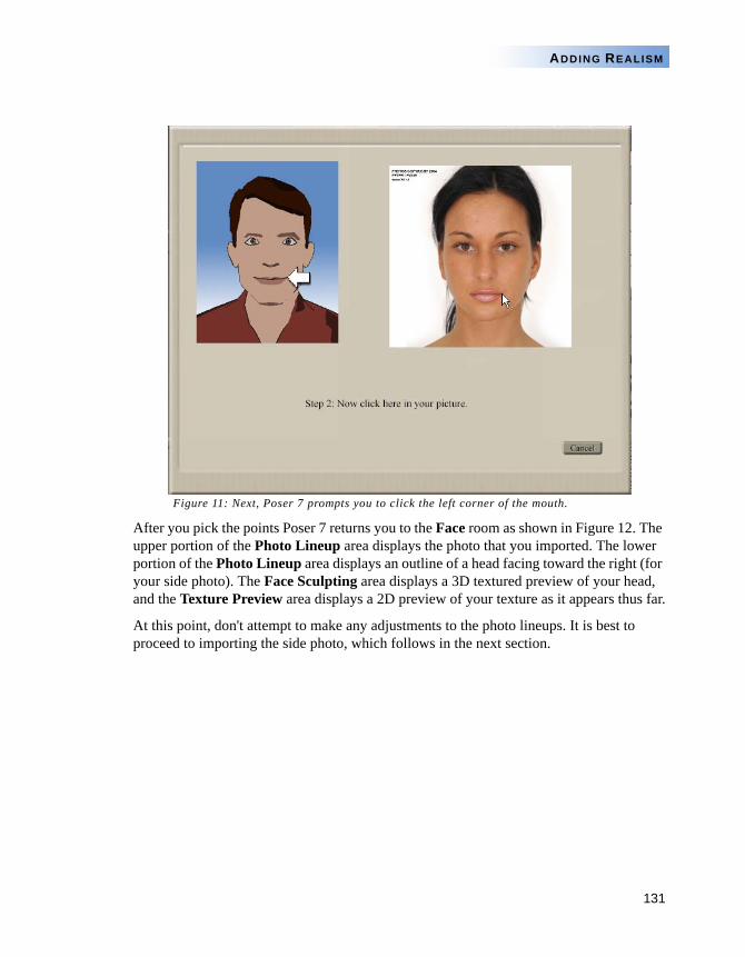
131
ADDING REALISM
Figure 11: Next, Poser 7 prompts you to click the left corner of the mouth.
After you pick the points Poser 7 returns you to the Face room as shown in Figure 12. The upper portion of the Photo Lineup area displays the photo that you imported. The lower portion of the Photo Lineup area displays an outline of a head facing toward the right (for your side photo). The Face Sculpting area displays a 3D textured preview of your head, and the Texture Preview area displays a 2D preview of your texture as it appears thus far.
At this point, don't attempt to make any adjustments to the photo lineups. It is best to proceed to importing the side photo, which follows in the next section.
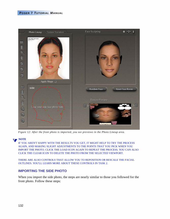
132
POSER 7 TUTORIAL MANUAL
Figure 12: After the front photo is imported, you see previews in the Photo Lineup area.
NOTEIF YOU AREN'T HAPPY WITH THE RESULTS YOU GET, IT MIGHT HELP TO TRY THE PROCESS AGAIN, AND MAKING SLIGHT ADJUSTMENTS TO THE POINTS THAT YOU PICK WHEN YOU IMPORT THE PHOTO. CLICK THE LOAD ICON AGAIN TO REPEAT THE PROCESS. YOU CAN ALSO CLICK THE CLEAR ICON TO DELETE THE PHOTO FROM THE SELECTED VIEWPORT.
THERE ARE ALSO CONTROLS THAT ALLOW YOU TO REPOSITION OR RESCALE THE FACIAL OUTLINES. YOU'LL LEARN MORE ABOUT THESE CONTROLS IN TASK 2.
IMPORTING THE SIDE PHOTO
When you import the side photo, the steps are nearly similar to those you followed for the front photo. Follow these steps:
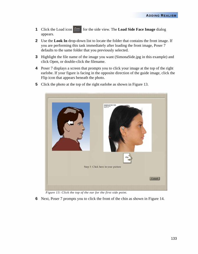
133
ADDING REALISM
1 Click the Load icon for the side view. The Load Side Face Image dialog appears.
2 Use the Look In drop-down list to locate the folder that contains the front image. If you are performing this task immediately after loading the front image, Poser 7 defaults to the same folder that you previously selected.
3 Highlight the file name of the image you want (SimonaSide.jpg in this example) and click Open, or double-click the filename.
4 Poser 7 displays a screen that prompts you to click your image at the top of the right earlobe. If your figure is facing in the opposite direction of the guide image, click the Flip icon that appears beneath the photo.
5 Click the photo at the top of the right earlobe as shown in Figure 13.
Figure 13: Click the top of the ear for the first side point.
6 Next, Poser 7 prompts you to click the front of the chin as shown in Figure 14.
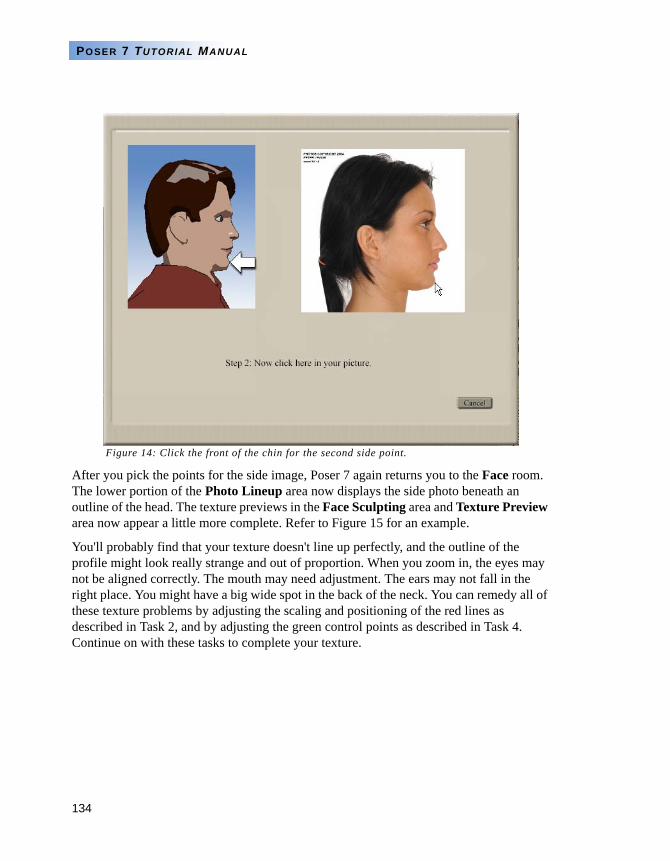
134
POSER 7 TUTORIAL MANUAL
Figure 14: Click the front of the chin for the second side point.
After you pick the points for the side image, Poser 7 again returns you to the Face room. The lower portion of the Photo Lineup area now displays the side photo beneath an outline of the head. The texture previews in the Face Sculpting area and Texture Preview area now appear a little more complete. Refer to Figure 15 for an example.
You'll probably find that your texture doesn't line up perfectly, and the outline of the profile might look really strange and out of proportion. When you zoom in, the eyes may not be aligned correctly. The mouth may need adjustment. The ears may not fall in the right place. You might have a big wide spot in the back of the neck. You can remedy all of these texture problems by adjusting the scaling and positioning of the red lines as described in Task 2, and by adjusting the green control points as described in Task 4. Continue on with these tasks to complete your texture.

135
ADDING REALISM
Figure 15: Front and side photos are loaded and the texture preview is more complete.
TASK 2: MOVING, SCALING, OR ROTATING THE HEAD GUIDES
After you complete Task 1, you may notice that the texture does not align perfectly with the character's features. There are several controls in the Photo Lineup area that allow you to fine tune the photo placement on the texture. Other controls help you align the head geometry so that it better matches the photo. This task shows you how to make these adjustments.
NOTEIF YOU DID NOT COMPLETE TASK 1, YOU CAN OPEN THE FACEROOMTASK2.PZZ FILE FROM THE TUTORIALS/FACEROOM FOLDER IN YOUR POSER 7 INSTALLATION TO FOLLOW ALONG FROM THIS POINT.
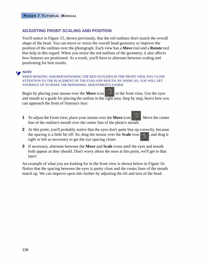
136
POSER 7 TUTORIAL MANUAL
ADJUSTING FRONT SCALING AND POSITION
You'll notice in Figure 15, shown previously, that the red outlines don't match the overall shape of the head. You can move or resize the overall head geometry to improve the position of the outlines over the photograph. Each view has a Move tool and a Rotate tool that help in this regard. When you resize the red outlines of the geometry, it also affects how features are positioned. As a result, you'll have to alternate between scaling and positioning for best results.
NOTEWHEN RESIZING AND REPOSITIONING THE RED OUTLINES IN THE FRONT VIEW, PAY CLOSE ATTENTION TO THE PLACEMENT OF THE EYES AND MOUTH. BY DOING SO, YOU WILL SET YOURSELF UP TO MAKE THE REMAINING ADJUSTMENTS EASIER.
Begin by placing your mouse over the Move icon in the front view. Use the eyes and mouth as a guide for placing the outline in the right area. Step by step, here's how you can approach the front of Simona's face:
1 To adjust the Front view, place your mouse over the Move icon . Move the center line of the outline's mouth over the center line of the photo's mouth.
2 At this point, you'll probably notice that the eyes don't quite line up correctly, because the spacing is a little bit off. So, drag the mouse over the Scale icon , and drag it right or left as necessary to get the eye spacing closer.
3 If necessary, alternate between the Move and Scale icons until the eyes and mouth both appear as they should. Don't worry about the nose at this point, we'll get to that later!
An example of what you are looking for in the front view is shown below in Figure 16. Notice that the spacing between the eyes is pretty close and the center lines of the mouth match up. We can improve upon this further by adjusting the tilt and turn of the head.
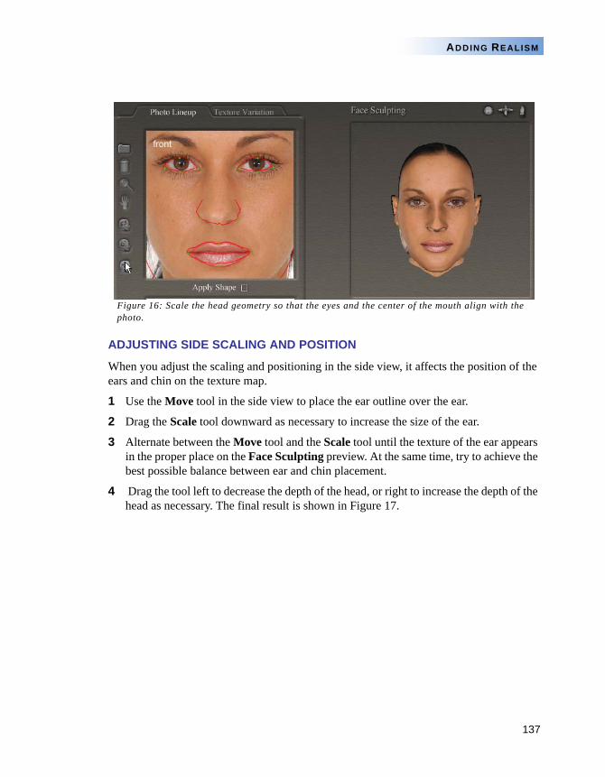
137
ADDING REALISM
Figure 16: Scale the head geometry so that the eyes and the center of the mouth align with the photo.
ADJUSTING SIDE SCALING AND POSITION
When you adjust the scaling and positioning in the side view, it affects the position of the ears and chin on the texture map.
1 Use the Move tool in the side view to place the ear outline over the ear.
2 Drag the Scale tool downward as necessary to increase the size of the ear.
3 Alternate between the Move tool and the Scale tool until the texture of the ear appears in the proper place on the Face Sculpting preview. At the same time, try to achieve the best possible balance between ear and chin placement.
4 Drag the tool left to decrease the depth of the head, or right to increase the depth of the head as necessary. The final result is shown in Figure 17.
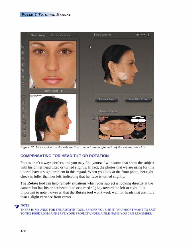
138
POSER 7 TUTORIAL MANUAL
Figure 17: Move and scale the side outline to match the height ratio of the ear and the chin.
COMPENSATING FOR HEAD TILT OR ROTATION
Photos aren't always perfect, and you may find yourself with some that show the subject with his or her head tilted or turned slightly. In fact, the photos that we are using for this tutorial have a slight problem in this regard. When you look at the front photo, her right cheek is fuller than her left, indicating that her face is turned slightly.
The Rotate tool can help remedy situations when your subject is looking directly at the camera but has his or her head tilted or turned slightly toward the left or right. It is important to note, however, that the Rotate tool won't work well for heads that are more than a slight variance from center.
NOTETHERE IS NO UNDO FOR THE ROTATE TOOL. BEFORE YOU USE IT, YOU MIGHT WANT TO EXIT TO THE POSE ROOM AND SAVE YOUR PROJECT UNDER A FILE NAME YOU CAN REMEMBER
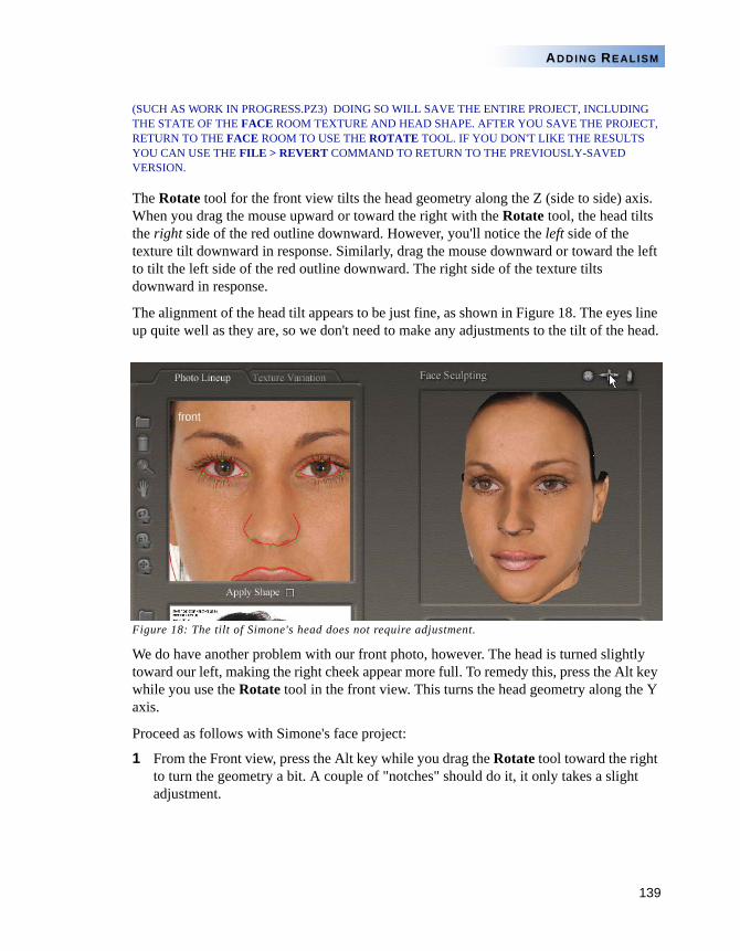
139
ADDING REALISM
(SUCH AS WORK IN PROGRESS.PZ3) DOING SO WILL SAVE THE ENTIRE PROJECT, INCLUDING THE STATE OF THE FACE ROOM TEXTURE AND HEAD SHAPE. AFTER YOU SAVE THE PROJECT, RETURN TO THE FACE ROOM TO USE THE ROTATE TOOL. IF YOU DON'T LIKE THE RESULTS YOU CAN USE THE FILE > REVERT COMMAND TO RETURN TO THE PREVIOUSLY-SAVED VERSION.
The Rotate tool for the front view tilts the head geometry along the Z (side to side) axis. When you drag the mouse upward or toward the right with the Rotate tool, the head tilts the right side of the red outline downward. However, you'll notice the left side of the texture tilt downward in response. Similarly, drag the mouse downward or toward the left to tilt the left side of the red outline downward. The right side of the texture tilts downward in response.
The alignment of the head tilt appears to be just fine, as shown in Figure 18. The eyes line up quite well as they are, so we don't need to make any adjustments to the tilt of the head.
Figure 18: The tilt of Simone's head does not require adjustment.
We do have another problem with our front photo, however. The head is turned slightly toward our left, making the right cheek appear more full. To remedy this, press the Alt key while you use the Rotate tool in the front view. This turns the head geometry along the Y axis.
Proceed as follows with Simone's face project:
1 From the Front view, press the Alt key while you drag the Rotate tool toward the right to turn the geometry a bit. A couple of "notches" should do it, it only takes a slight adjustment.
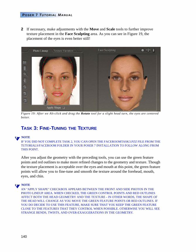
140
POSER 7 TUTORIAL MANUAL
2 If necessary, make adjustments with the Move and Scale tools to further improve texture placement in the Face Sculpting area. As you can see in Figure 19, the placement of the eyes is even better still!
Figure 19: After we Alt-click and drag the Rotate tool for a slight head turn, the eyes are centered better.
TASK 3: FINE-TUNING THE TEXTURE
NOTEIF YOU DID NOT COMPLETE TASK 2, YOU CAN OPEN THE FACEROOMTASK3.PZZ FILE FROM THE TUTORIALS/FACEROOM FOLDER IN YOUR POSER 7 INSTALLATION TO FOLLOW ALONG FROM THIS POINT.
After you adjust the geometry with the preceding tools, you can use the green feature points and red outlines to make more refined changes to the geometry and texture. Though the texture placement is acceptable over the eyes and mouth at this point, the green feature points will allow you to fine-tune and smooth the texture around the forehead, mouth, eyes, and chin.
NOTEAN "APPLY SHAPE" CHECKBOX APPEARS BETWEEN THE FRONT AND SIDE PHOTOS IN THE PHOTO LINEUP AREA. WHEN CHECKED, THE GREEN CONTROL POINTS AND RED OUTLINES AFFECT BOTH THE HEAD GEOMETRY AND THE TEXTURE - IN OTHER WORDS, THE SHAPE OF THE HEAD WILL CHANGE AS YOU MOVE THE GREEN FEATURE POINTS OR RED OUTLINES. IF YOU DO DECIDE TO USE THIS FEATURE, MAKE SURE THAT YOU KEEP THE GREEN FEATURE CLOSE TO THE FEATURES THAT THEY CONTROL WHEN POSSIBLE. OTHERWISE YOU WILL SEE STRANGE BENDS, TWISTS, AND OVER-EXAGGERATIONS IN THE GEOMETRY.
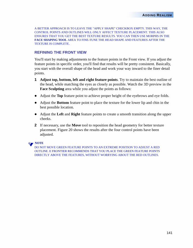
141
ADDING REALISM
A BETTER APPROACH IS TO LEAVE THE "APPLY SHAPE" CHECKBOX EMPTY. THIS WAY, THE CONTROL POINTS AND OUTLINES WILL ONLY AFFECT TEXTURE PLACEMENT. THIS ALSO ENSURES THAT YOU GET THE BEST TEXTURE RESULTS. YOU CAN THEN USE MORPHS IN THE FACE SHAPING TOOL AREA TO FINE-TUNE THE HEAD SHAPE AND FEATURES AFTER THE TEXTURE IS COMPLETE.
REFINING THE FRONT VIEW
You'll start by making adjustments to the feature points in the Front view. If you adjust the feature points in specific order, you'll find that results will be pretty consistent. Basically, you start with the overall shape of the head and work your way inward to the finer detail points.
1 Adjust top, bottom, left and right feature points. Try to maintain the best outline of the head, while matching the eyes as closely as possible. Watch the 3D preview in the Face Sculpting area while you adjust the points as follows:
Adjust the Top feature point to achieve proper height of the eyebrows and eye folds.
Adjust the Bottom feature point to place the texture for the lower lip and chin in the best possible location.
Adjust the Left and Right feature points to create a smooth transition along the upper cheeks.
2 If necessary, use the Move tool to reposition the head geometry for better texture placement. Figure 20 shows the results after the four control points have been adjusted.
NOTEDO NOT MOVE GREEN FEATURE POINTS TO AN EXTREME POSITION TO ADJUST A RED OUTLINE. E FRONTIER RECOMMENDS THAT YOU PLACE THE GREEN FEATURE POINTS DIRECTLY ABOVE THE FEATURES, WITHOUT WORRYING ABOUT THE RED OUTLINES.
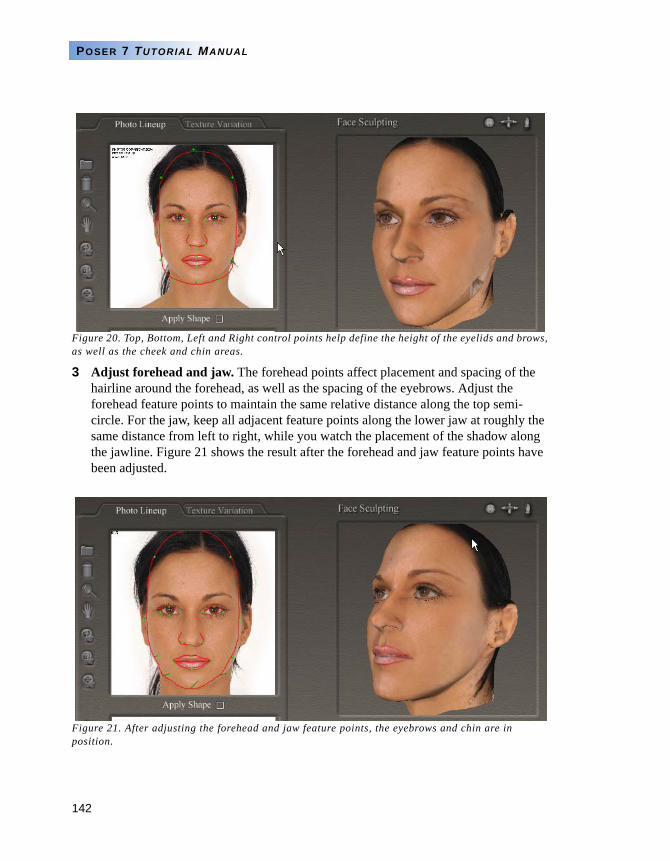
142
POSER 7 TUTORIAL MANUAL
Figure 20. Top, Bottom, Left and Right control points help define the height of the eyelids and brows, as well as the cheek and chin areas.
3 Adjust forehead and jaw. The forehead points affect placement and spacing of the hairline around the forehead, as well as the spacing of the eyebrows. Adjust the forehead feature points to maintain the same relative distance along the top semi-circle. For the jaw, keep all adjacent feature points along the lower jaw at roughly the same distance from left to right, while you watch the placement of the shadow along the jawline. Figure 21 shows the result after the forehead and jaw feature points have been adjusted.
Figure 21. After adjusting the forehead and jaw feature points, the eyebrows and chin are in position.
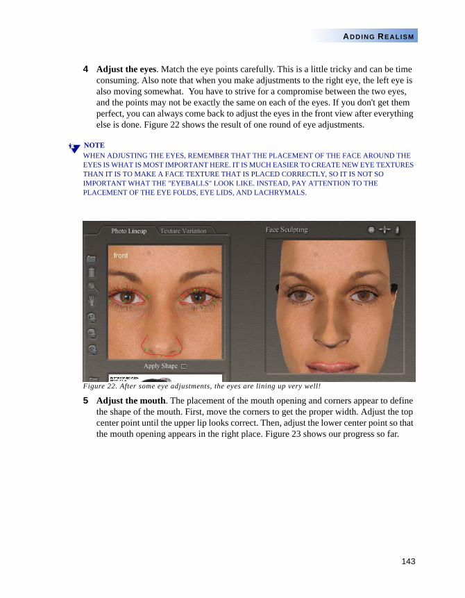
143
ADDING REALISM
4 Adjust the eyes. Match the eye points carefully. This is a little tricky and can be time consuming. Also note that when you make adjustments to the right eye, the left eye is also moving somewhat. You have to strive for a compromise between the two eyes, and the points may not be exactly the same on each of the eyes. If you don't get them perfect, you can always come back to adjust the eyes in the front view after everything else is done. Figure 22 shows the result of one round of eye adjustments.
NOTEWHEN ADJUSTING THE EYES, REMEMBER THAT THE PLACEMENT OF THE FACE AROUND THE EYES IS WHAT IS MOST IMPORTANT HERE. IT IS MUCH EASIER TO CREATE NEW EYE TEXTURES THAN IT IS TO MAKE A FACE TEXTURE THAT IS PLACED CORRECTLY, SO IT IS NOT SO IMPORTANT WHAT THE "EYEBALLS" LOOK LIKE. INSTEAD, PAY ATTENTION TO THE PLACEMENT OF THE EYE FOLDS, EYE LIDS, AND LACHRYMALS.
Figure 22. After some eye adjustments, the eyes are lining up very well!
5 Adjust the mouth. The placement of the mouth opening and corners appear to define the shape of the mouth. First, move the corners to get the proper width. Adjust the top center point until the upper lip looks correct. Then, adjust the lower center point so that the mouth opening appears in the right place. Figure 23 shows our progress so far.
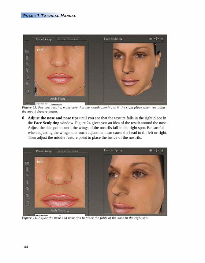
144
POSER 7 TUTORIAL MANUAL
Figure 23. For best results, make sure that the mouth opening is in the right place when you adjust the mouth feature points.
6 Adjust the nose and nose tips until you see that the texture falls in the right place in the Face Sculpting window. Figure 24 gives you an idea of the result around the nose. Adjust the side points until the wings of the nostrils fall in the right spot. Be careful when adjusting the wings: too much adjustment can cause the head to tilt left or right. Then adjust the middle feature point to place the inside of the nostrils.
Figure 24: Adjust the nose and nose tips to place the folds of the nose in the right spot.
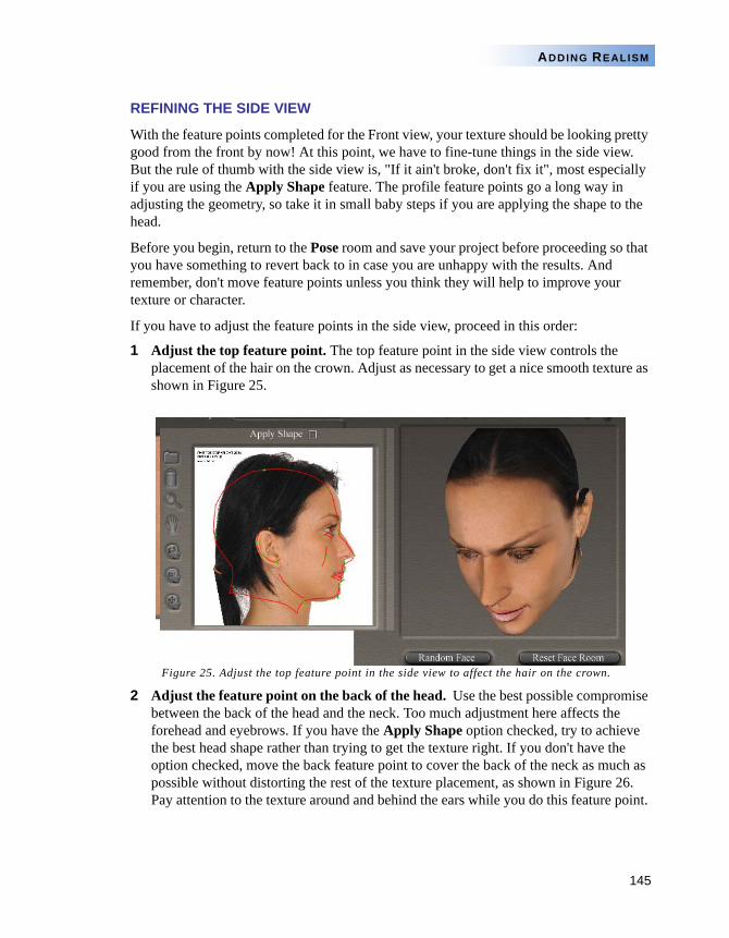
145
ADDING REALISM
REFINING THE SIDE VIEW
With the feature points completed for the Front view, your texture should be looking pretty good from the front by now! At this point, we have to fine-tune things in the side view. But the rule of thumb with the side view is, "If it ain't broke, don't fix it", most especially if you are using the Apply Shape feature. The profile feature points go a long way in adjusting the geometry, so take it in small baby steps if you are applying the shape to the head.
Before you begin, return to the Pose room and save your project before proceeding so that you have something to revert back to in case you are unhappy with the results. And remember, don't move feature points unless you think they will help to improve your texture or character.
If you have to adjust the feature points in the side view, proceed in this order:
1 Adjust the top feature point. The top feature point in the side view controls the placement of the hair on the crown. Adjust as necessary to get a nice smooth texture as shown in Figure 25.
Figure 25. Adjust the top feature point in the side view to affect the hair on the crown.
2 Adjust the feature point on the back of the head. Use the best possible compromise between the back of the head and the neck. Too much adjustment here affects the forehead and eyebrows. If you have the Apply Shape option checked, try to achieve the best head shape rather than trying to get the texture right. If you don't have the option checked, move the back feature point to cover the back of the neck as much as possible without distorting the rest of the texture placement, as shown in Figure 26. Pay attention to the texture around and behind the ears while you do this feature point.
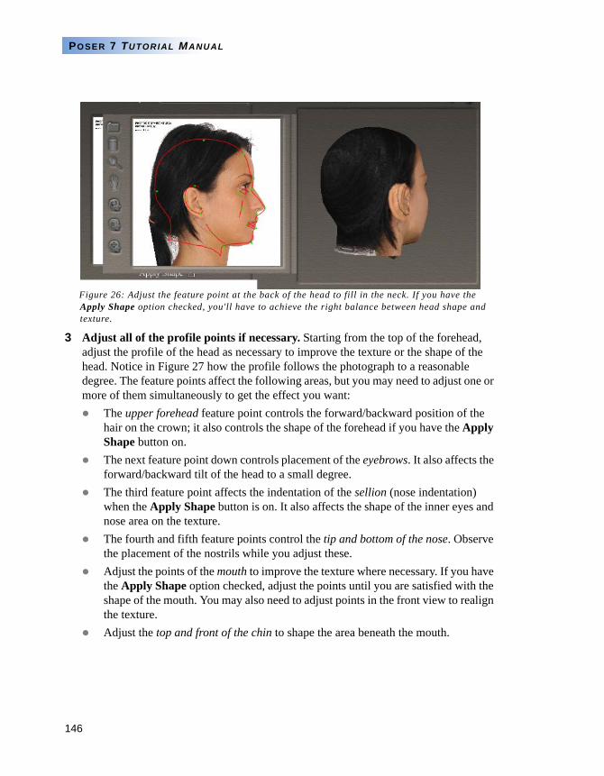
146
POSER 7 TUTORIAL MANUAL
Figure 26: Adjust the feature point at the back of the head to fill in the neck. If you have the Apply Shape option checked, you'll have to achieve the right balance between head shape and texture.
3 Adjust all of the profile points if necessary. Starting from the top of the forehead, adjust the profile of the head as necessary to improve the texture or the shape of the head. Notice in Figure 27 how the profile follows the photograph to a reasonable degree. The feature points affect the following areas, but you may need to adjust one or more of them simultaneously to get the effect you want:
The upper forehead feature point controls the forward/backward position of the hair on the crown; it also controls the shape of the forehead if you have the Apply Shape button on.The next feature point down controls placement of the eyebrows. It also affects the forward/backward tilt of the head to a small degree.The third feature point affects the indentation of the sellion (nose indentation) when the Apply Shape button is on. It also affects the shape of the inner eyes and nose area on the texture.The fourth and fifth feature points control the tip and bottom of the nose. Observe the placement of the nostrils while you adjust these.Adjust the points of the mouth to improve the texture where necessary. If you have the Apply Shape option checked, adjust the points until you are satisfied with the shape of the mouth. You may also need to adjust points in the front view to realign the texture.Adjust the top and front of the chin to shape the area beneath the mouth.
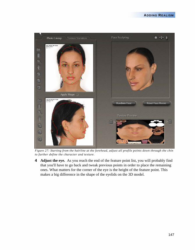
147
ADDING REALISM
Figure 27: Starting from the hairline at the forehead, adjust all profile points down through the chin to further define the character and texture.
4 Adjust the eye. As you reach the end of the feature point list, you will probably find that you'll have to go back and tweak previous points in order to place the remaining ones. What matters for the corner of the eye is the height of the feature point. This makes a big difference in the shape of the eyelids on the 3D model.
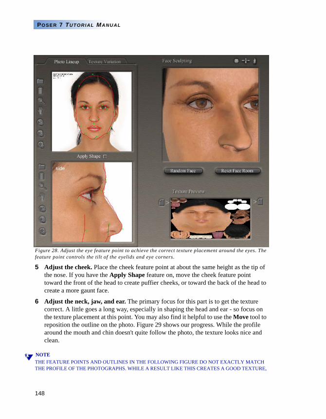
148
POSER 7 TUTORIAL MANUAL
Figure 28. Adjust the eye feature point to achieve the correct texture placement around the eyes. The feature point controls the tilt of the eyelids and eye corners.
5 Adjust the cheek. Place the cheek feature point at about the same height as the tip of the nose. If you have the Apply Shape feature on, move the cheek feature point toward the front of the head to create puffier cheeks, or toward the back of the head to create a more gaunt face.
6 Adjust the neck, jaw, and ear. The primary focus for this part is to get the texture correct. A little goes a long way, especially in shaping the head and ear - so focus on the texture placement at this point. You may also find it helpful to use the Move tool to reposition the outline on the photo. Figure 29 shows our progress. While the profile around the mouth and chin doesn't quite follow the photo, the texture looks nice and clean.
NOTETHE FEATURE POINTS AND OUTLINES IN THE FOLLOWING FIGURE DO NOT EXACTLY MATCH THE PROFILE OF THE PHOTOGRAPHS. WHILE A RESULT LIKE THIS CREATES A GOOD TEXTURE,
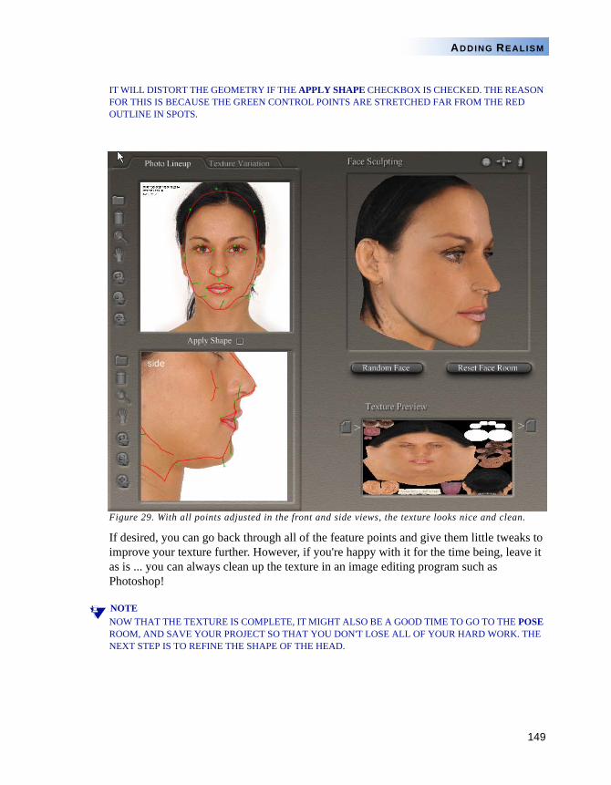
149
ADDING REALISM
IT WILL DISTORT THE GEOMETRY IF THE APPLY SHAPE CHECKBOX IS CHECKED. THE REASON FOR THIS IS BECAUSE THE GREEN CONTROL POINTS ARE STRETCHED FAR FROM THE RED OUTLINE IN SPOTS.
Figure 29. With all points adjusted in the front and side views, the texture looks nice and clean.
If desired, you can go back through all of the feature points and give them little tweaks to improve your texture further. However, if you're happy with it for the time being, leave it as is ... you can always clean up the texture in an image editing program such as Photoshop!
NOTENOW THAT THE TEXTURE IS COMPLETE, IT MIGHT ALSO BE A GOOD TIME TO GO TO THE POSE ROOM, AND SAVE YOUR PROJECT SO THAT YOU DON'T LOSE ALL OF YOUR HARD WORK. THE NEXT STEP IS TO REFINE THE SHAPE OF THE HEAD.
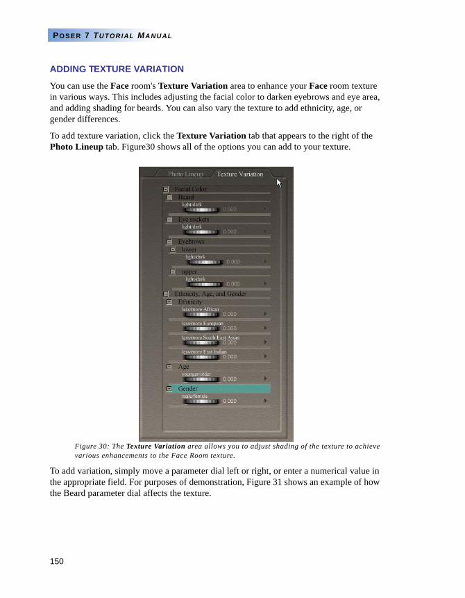
150
POSER 7 TUTORIAL MANUAL
ADDING TEXTURE VARIATION
You can use the Face room's Texture Variation area to enhance your Face room texture in various ways. This includes adjusting the facial color to darken eyebrows and eye area, and adding shading for beards. You can also vary the texture to add ethnicity, age, or gender differences.
To add texture variation, click the Texture Variation tab that appears to the right of the Photo Lineup tab. Figure30 shows all of the options you can add to your texture.
Figure 30: The Texture Variation area allows you to adjust shading of the texture to achieve various enhancements to the Face Room texture.
To add variation, simply move a parameter dial left or right, or enter a numerical value in the appropriate field. For purposes of demonstration, Figure 31 shows an example of how the Beard parameter dial affects the texture.
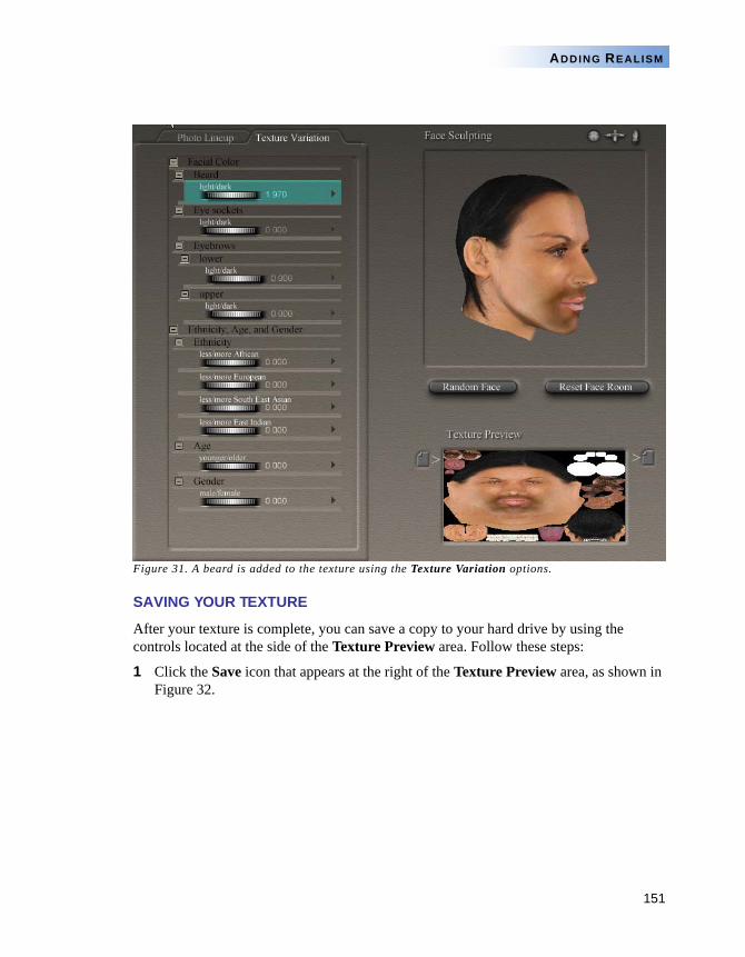
151
ADDING REALISM
Figure 31. A beard is added to the texture using the Texture Variation options.
SAVING YOUR TEXTURE
After your texture is complete, you can save a copy to your hard drive by using the controls located at the side of the Texture Preview area. Follow these steps:
1 Click the Save icon that appears at the right of the Texture Preview area, as shown in Figure 32.
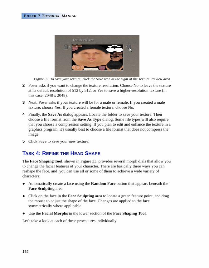
152
POSER 7 TUTORIAL MANUAL
Figure 32. To save your texture, click the Save icon at the right of the Texture Preview area.
2 Poser asks if you want to change the texture resolution. Choose No to leave the texture at its default resolution of 512 by 512, or Yes to save a higher-resolution texture (in this case, 2048 x 2048).
3 Next, Poser asks if your texture will be for a male or female. If you created a male texture, choose Yes. If you created a female texture, choose No.
4 Finally, the Save As dialog appears. Locate the folder to save your texture. Then choose a file format from the Save As Type dialog. Some file types will also require that you choose a compression setting. If you plan to edit and enhance the texture in a graphics program, it's usually best to choose a file format that does not compress the image.
5 Click Save to save your new texture.
TASK 4: REFINE THE HEAD SHAPE
The Face Shaping Tool, shown in Figure 33, provides several morph dials that allow you to change the facial features of your character. There are basically three ways you can reshape the face, and you can use all or some of them to achieve a wide variety of characters:
Automatically create a face using the Random Face button that appears beneath the Face Sculpting area.
Click on the face in the Face Sculpting area to locate a green feature point, and drag the mouse to adjust the shape of the face. Changes are applied to the face symmetrically where applicable.
Use the Facial Morphs in the lower section of the Face Shaping Tool.
Let's take a look at each of these procedures individually.
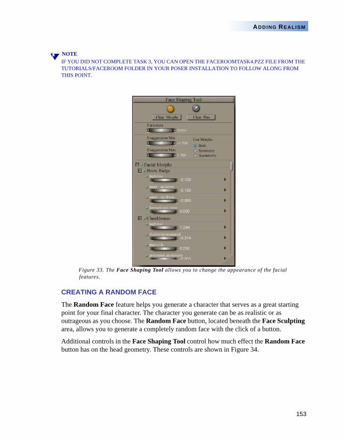
153
ADDING REALISM
NOTEIF YOU DID NOT COMPLETE TASK 3, YOU CAN OPEN THE FACEROOMTASK4.PZZ FILE FROM THE TUTORIALS/FACEROOM FOLDER IN YOUR POSER INSTALLATION TO FOLLOW ALONG FROM THIS POINT.
Figure 33. The Face Shaping Tool allows you to change the appearance of the facial features.
CREATING A RANDOM FACE
The Random Face feature helps you generate a character that serves as a great starting point for your final character. The character you generate can be as realistic or as outrageous as you choose. The Random Face button, located beneath the Face Sculpting area, allows you to generate a completely random face with the click of a button.
Additional controls in the Face Shaping Tool control how much effect the Random Face button has on the head geometry. These controls are shown in Figure 34.
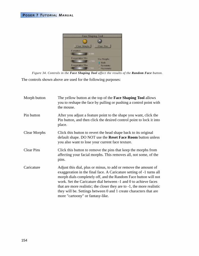
154
POSER 7 TUTORIAL MANUAL
Figure 34. Controls in the Face Shaping Tool affect the results of the Random Face button.
The controls shown above are used for the following purposes:
Morph button The yellow button at the top of the Face Shaping Tool allows you to reshape the face by pulling or pushing a control point with the mouse.
Pin button After you adjust a feature point to the shape you want, click the Pin button, and then click the desired control point to lock it into place.
Clear Morphs Click this button to revert the head shape back to its original default shape. DO NOT use the Reset Face Room button unless you also want to lose your current face texture.
Clear Pins Click this button to remove the pins that keep the morphs from affecting your facial morphs. This removes all, not some, of the pins.
Caricature Adjust this dial, plus or minus, to add or remove the amount of exaggeration in the final face. A Caricature setting of -1 turns all morph dials completely off, and the Random Face button will not work. Set the Caricature dial between -1 and 0 to achieve faces that are more realistic; the closer they are to -1, the more realistic they will be. Settings between 0 and 1 create characters that are more "cartoony" or fantasy-like.

155
ADDING REALISM
To create a random face, follow these steps:
1 Set the Caricature dial, if desired, to a value other than -1. For more realistic characters, set this value closer to -1. For more extreme characters, move the setting more toward 1. A good compromise is -.5. You can also adjust the dial left or right at any time to affect the amount of caricature after you use the Random Face button or other morphs.
2 Set the Exaggeration Min and Exaggeration Max dials to the lowest and highest values (respectively) that you want the morph dials to target. A min value of -.15 and a max value of .15 creates very good starting points for realistic characters.
3 Decide whether you want the morphs to affect Symmetry (same changes right and left), Asymmetry (differences in right to left), or both.
4 Press the Random Face button under the Face Sculpting area until you get a face that you like. Figure 35 shows some examples achieved with Caricature at -.5, Exaggeration Min at -.15, Exaggeration Max at .15, and "Both" selected for Morphs options. As you can see, the faces truly are random and offer a great starting point for characters. You can also go back and adjust the settings you selected in steps 1 to 3 to get even more varied results.
Exaggeration Min Adjust this dial to the minimum amount of affect that you want each of the facial morphs to have. The default setting is -1.5. If you don't want any of the facial morphs to work in a negative setting, you can set this at 0. If you want the Random Face button to have a smaller effect on the overall shape of the face, you can decrease this setting to -.15. This results in random faces that are a bit more realistic and less characterized.
Exaggeration Max Adjust this dial to the maximum amount of effect that you want each of the facial morphs to have. The default is 1.5, but setting it at a smaller value (such as .15) results in random faces that are a bit more realistic and less characterized.
Use Morphs There are three Use Morphs options: Both (the default), Symmetry, and Asymmetry. When Both is selected, the morph dials will make symmetrical and asymmetrical changes to the face. With Symmetry selected, the only changes made to the face will be symmetrical changes. With Asymmetry selected, the only changes made to the face will be asymmetrical.
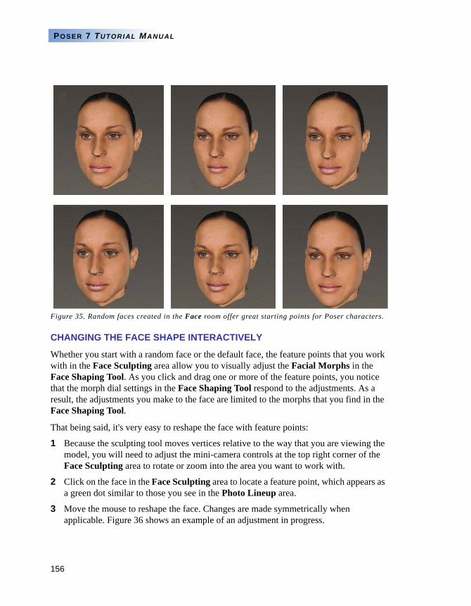
156
POSER 7 TUTORIAL MANUAL
Figure 35. Random faces created in the Face room offer great starting points for Poser characters.
CHANGING THE FACE SHAPE INTERACTIVELY
Whether you start with a random face or the default face, the feature points that you work with in the Face Sculpting area allow you to visually adjust the Facial Morphs in the Face Shaping Tool. As you click and drag one or more of the feature points, you notice that the morph dial settings in the Face Shaping Tool respond to the adjustments. As a result, the adjustments you make to the face are limited to the morphs that you find in the Face Shaping Tool.
That being said, it's very easy to reshape the face with feature points:
1 Because the sculpting tool moves vertices relative to the way that you are viewing the model, you will need to adjust the mini-camera controls at the top right corner of the Face Sculpting area to rotate or zoom into the area you want to work with.
2 Click on the face in the Face Sculpting area to locate a feature point, which appears as a green dot similar to those you see in the Photo Lineup area.
3 Move the mouse to reshape the face. Changes are made symmetrically when applicable. Figure 36 shows an example of an adjustment in progress.
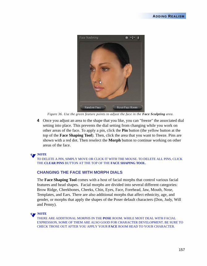
157
ADDING REALISM
Figure 36. Use the green feature points to adjust the face in the Face Sculpting area.
4 Once you adjust an area to the shape that you like, you can "freeze" the associated dial setting into place. This prevents the dial setting from changing while you work on other areas of the face. To apply a pin, click the Pin button (the yellow button at the top of the Face Shaping Tool). Then, click the area that you want to freeze. Pins are shown with a red dot. Then reselect the Morph button to continue working on other areas of the face.
NOTETO DELETE A PIN, SIMPLY MOVE OR CLICK IT WITH THE MOUSE. TO DELETE ALL PINS, CLICK THE CLEAR PINS BUTTON AT THE TOP OF THE FACE SHAPING TOOL.
CHANGING THE FACE WITH MORPH DIALS
The Face Shaping Tool comes with a host of facial morphs that control various facial features and head shapes. Facial morphs are divided into several different categories: Brow Ridge, Cheekbones, Cheeks, Chin, Eyes, Face, Forehead, Jaw, Mouth, Nose, Templates, and Ears. There are also additional morphs that affect ethnicity, age, and gender, or morphs that apply the shapes of the Poser default characters (Don, Judy, Will and Penny).
NOTETHERE ARE ADDITIONAL MORPHS IN THE POSE ROOM. WHILE MOST DEAL WITH FACIAL EXPRESSION, SOME OF THEM ARE ALSO GOOD FOR CHARACTER DEVELOPMENT. BE SURE TO CHECK THOSE OUT AFTER YOU APPLY YOUR FACE ROOM HEAD TO YOUR CHARACTER.
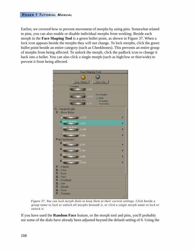
158
POSER 7 TUTORIAL MANUAL
Earlier, we covered how to prevent movement of morphs by using pins. Somewhat related to pins, you can also enable or disable individual morphs from working. Beside each morph in the Face Shaping Tool is a green bullet point, as shown in Figure 37. When a lock icon appears beside the morphs they will not change. To lock morphs, click the green bullet point beside an entire category (such as Cheekbones). This prevents an entire group of morphs from being affected. To unlock the morph, click the padlock icon to change it back into a bullet. You can also click a single morph (such as high/low or thin/wide) to prevent it from being affected.
Figure 37. You can lock morph dials to keep them at their current settings. Click beside a group name to lock or unlock all morphs beneath it, or click a single morph name to lock or unlock it.
If you have used the Random Face feature, or the morph tool and pins, you'll probably see some of the dials have already been adjusted beyond the default setting of 0. Using the
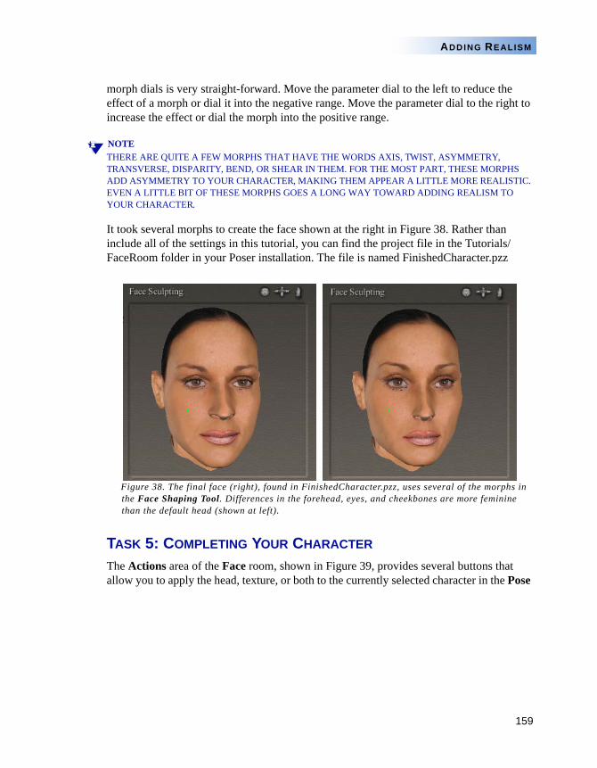
159
ADDING REALISM
morph dials is very straight-forward. Move the parameter dial to the left to reduce the effect of a morph or dial it into the negative range. Move the parameter dial to the right to increase the effect or dial the morph into the positive range.
NOTETHERE ARE QUITE A FEW MORPHS THAT HAVE THE WORDS AXIS, TWIST, ASYMMETRY, TRANSVERSE, DISPARITY, BEND, OR SHEAR IN THEM. FOR THE MOST PART, THESE MORPHS ADD ASYMMETRY TO YOUR CHARACTER, MAKING THEM APPEAR A LITTLE MORE REALISTIC. EVEN A LITTLE BIT OF THESE MORPHS GOES A LONG WAY TOWARD ADDING REALISM TO YOUR CHARACTER.
It took several morphs to create the face shown at the right in Figure 38. Rather than include all of the settings in this tutorial, you can find the project file in the Tutorials/FaceRoom folder in your Poser installation. The file is named FinishedCharacter.pzz
Figure 38. The final face (right), found in FinishedCharacter.pzz, uses several of the morphs in the Face Shaping Tool. Differences in the forehead, eyes, and cheekbones are more feminine than the default head (shown at left).
TASK 5: COMPLETING YOUR CHARACTER
The Actions area of the Face room, shown in Figure 39, provides several buttons that allow you to apply the head, texture, or both to the currently selected character in the Pose
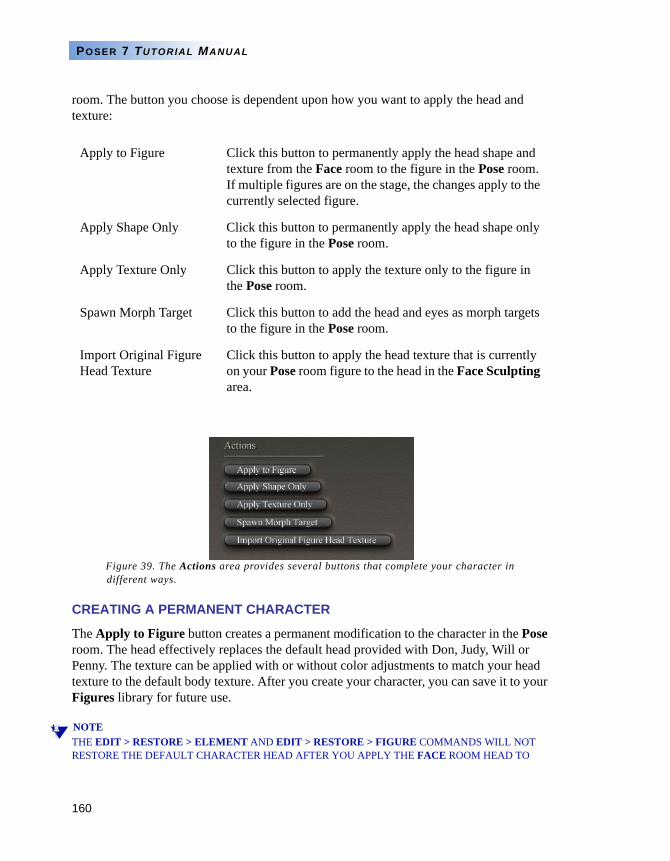
160
POSER 7 TUTORIAL MANUAL
room. The button you choose is dependent upon how you want to apply the head and texture:
Figure 39. The Actions area provides several buttons that complete your character in different ways.
CREATING A PERMANENT CHARACTER
The Apply to Figure button creates a permanent modification to the character in the Pose room. The head effectively replaces the default head provided with Don, Judy, Will or Penny. The texture can be applied with or without color adjustments to match your head texture to the default body texture. After you create your character, you can save it to your Figures library for future use.
NOTETHE EDIT > RESTORE > ELEMENT AND EDIT > RESTORE > FIGURE COMMANDS WILL NOT RESTORE THE DEFAULT CHARACTER HEAD AFTER YOU APPLY THE FACE ROOM HEAD TO
Apply to Figure Click this button to permanently apply the head shape and texture from the Face room to the figure in the Pose room. If multiple figures are on the stage, the changes apply to the currently selected figure.
Apply Shape Only Click this button to permanently apply the head shape only to the figure in the Pose room.
Apply Texture Only Click this button to apply the texture only to the figure in the Pose room.
Spawn Morph Target Click this button to add the head and eyes as morph targets to the figure in the Pose room.
Import Original Figure Head Texture
Click this button to apply the head texture that is currently on your Pose room figure to the head in the Face Sculpting area.
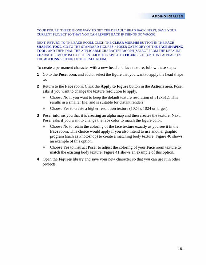
161
ADDING REALISM
YOUR FIGURE. THERE IS ONE WAY TO GET THE DEFAULT HEAD BACK. FIRST, SAVE YOUR CURRENT PROJECT SO THAT YOU CAN REVERT BACK IF THINGS GO WRONG.
NEXT, RETURN TO THE FACE ROOM, CLICK THE CLEAR MORPHS BUTTON IN THE FACE SHAPING TOOL. GO TO THE STANDARD FIGURES > POSER CATEGORY OF THE FACE SHAPING TOOL, AND THEN DIAL THE APPLICABLE CHARACTER MORPH (SELECT FROM THE DEFAULT CHARACTER MORPHS) TO 1. THEN CLICK THE APPLY TO FIGURE BUTTON THAT APPEARS IN THE ACTIONS SECTION OF THE FACE ROOM.
To create a permanent character with a new head and face texture, follow these steps:
1 Go to the Pose room, and add or select the figure that you want to apply the head shape to.
2 Return to the Face room. Click the Apply to Figure button in the Actions area. Poser asks if you want to change the texture resolution to apply.
Choose No if you want to keep the default texture resolution of 512x512. This results in a smaller file, and is suitable for distant renders.Choose Yes to create a higher resolution texture (1024 x 1024 or larger).
3 Poser informs you that it is creating an alpha map and then creates the texture. Next, Poser asks if you want to change the face color to match the figure color.
Choose No to retain the coloring of the face texture exactly as you see it in the Face room. This choice would apply if you also intend to use another graphic program (such as Photoshop) to create a matching body texture. Figure 40 shows an example of this option.Choose Yes to instruct Poser to adjust the coloring of your Face room texture to match the existing body texture. Figure 41 shows an example of this option.
4 Open the Figures library and save your new character so that you can use it in other projects.
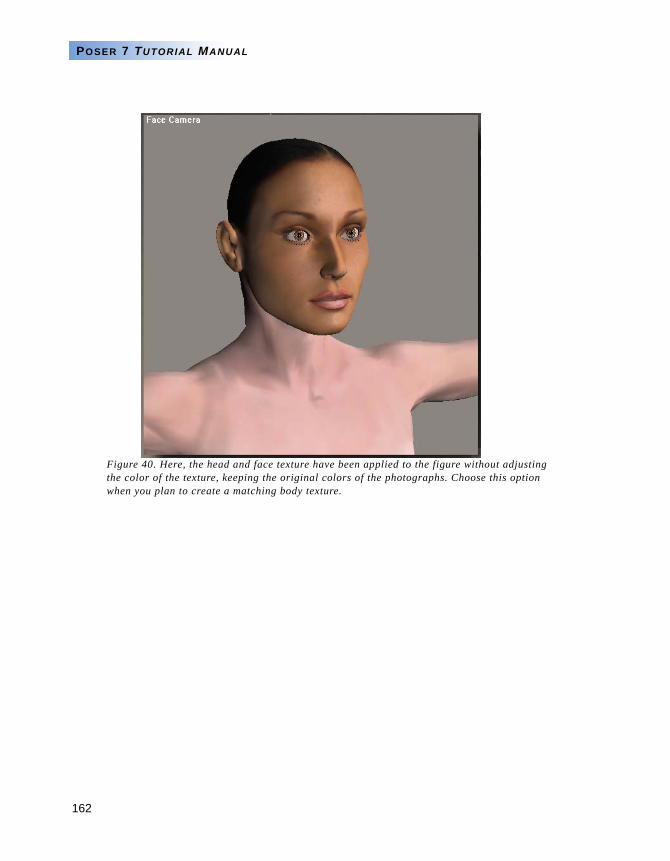
162
POSER 7 TUTORIAL MANUAL
Figure 40. Here, the head and face texture have been applied to the figure without adjusting the color of the texture, keeping the original colors of the photographs. Choose this option when you plan to create a matching body texture.
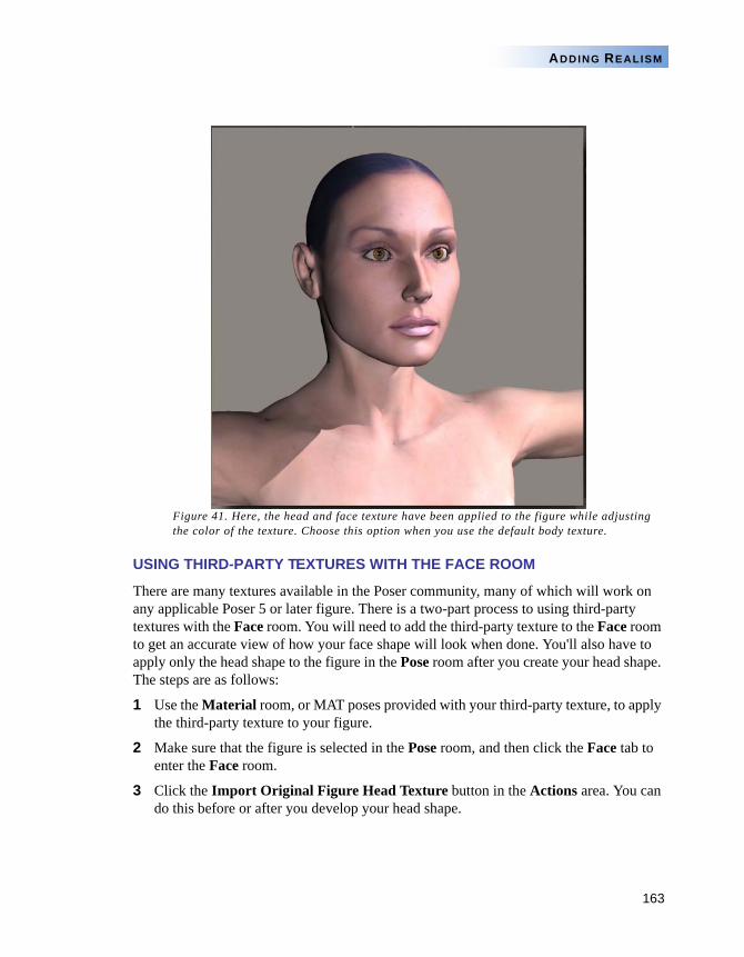
163
ADDING REALISM
Figure 41. Here, the head and face texture have been applied to the figure while adjusting the color of the texture. Choose this option when you use the default body texture.
USING THIRD-PARTY TEXTURES WITH THE FACE ROOM
There are many textures available in the Poser community, many of which will work on any applicable Poser 5 or later figure. There is a two-part process to using third-party textures with the Face room. You will need to add the third-party texture to the Face room to get an accurate view of how your face shape will look when done. You'll also have to apply only the head shape to the figure in the Pose room after you create your head shape. The steps are as follows:
1 Use the Material room, or MAT poses provided with your third-party texture, to apply the third-party texture to your figure.
2 Make sure that the figure is selected in the Pose room, and then click the Face tab to enter the Face room.
3 Click the Import Original Figure Head Texture button in the Actions area. You can do this before or after you develop your head shape.
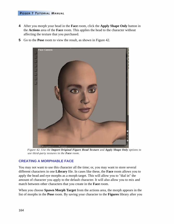
164
POSER 7 TUTORIAL MANUAL
4 After you morph your head in the Face room, click the Apply Shape Only button in the Actions area of the Face room. This applies the head to the character without affecting the texture that you purchased.
5 Go to the Pose room to view the result, as shown in Figure 42.
Figure 42. Use the Import Original Figure Head Texture and Apply Shape Only options to use third-party textures in the Face room.
CREATING A MORPHABLE FACE
You may not want to use this character all the time; or, you may want to store several different characters in one Library file. In cases like these, the Face room allows you to apply the head and eye morphs as a morph target. This will allow you to "dial in" the amount of character you apply to the default character. It will also allow you to mix and match between other characters that you create in the Face room.
When you choose Spawn Morph Target from the actions area, the morph appears in the list of morphs in the Pose room. By saving your character to the Figures library after you
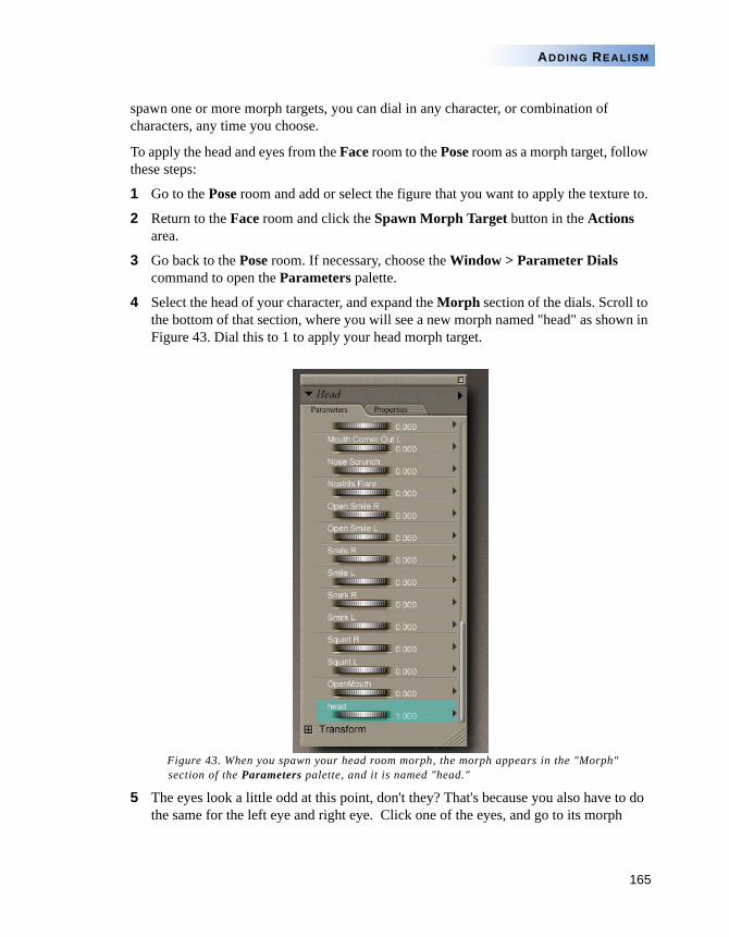
165
ADDING REALISM
spawn one or more morph targets, you can dial in any character, or combination of characters, any time you choose.
To apply the head and eyes from the Face room to the Pose room as a morph target, follow these steps:
1 Go to the Pose room and add or select the figure that you want to apply the texture to.
2 Return to the Face room and click the Spawn Morph Target button in the Actions area.
3 Go back to the Pose room. If necessary, choose the Window > Parameter Dials command to open the Parameters palette.
4 Select the head of your character, and expand the Morph section of the dials. Scroll to the bottom of that section, where you will see a new morph named "head" as shown in Figure 43. Dial this to 1 to apply your head morph target.
Figure 43. When you spawn your head room morph, the morph appears in the "Morph" section of the Parameters palette, and it is named "head."
5 The eyes look a little odd at this point, don't they? That's because you also have to do the same for the left eye and right eye. Click one of the eyes, and go to its morph
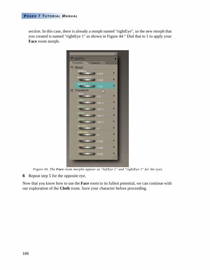
166
POSER 7 TUTORIAL MANUAL
section. In this case, there is already a morph named "rightEye", so the new morph that you created is named "rightEye 1" as shown in Figure 44." Dial that to 1 to apply your Face room morph.
Figure 44. The Face room morphs appear as "leftEye 1" and "rightEye 1" for the eyes.
6 Repeat step 5 for the opposite eye.
Now that you know how to use the Face room to its fullest potential, we can continue with our exploration of the Cloth room. Save your character before proceeding.
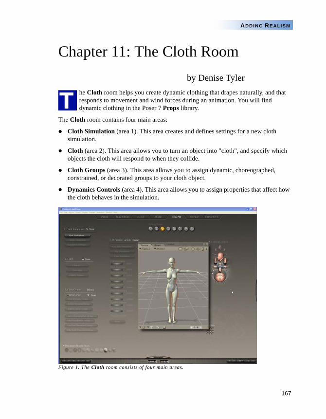
167
ADDING REALISM
Chapter 11: The Cloth Roomby Denise Tyler
he Cloth room helps you create dynamic clothing that drapes naturally, and that responds to movement and wind forces during an animation. You will find dynamic clothing in the Poser 7 Props library.
The Cloth room contains four main areas:
Cloth Simulation (area 1). This area creates and defines settings for a new cloth simulation.
Cloth (area 2). This area allows you to turn an object into "cloth", and specify which objects the cloth will respond to when they collide.
Cloth Groups (area 3). This area allows you to assign dynamic, choreographed, constrained, or decorated groups to your cloth object.
Dynamics Controls (area 4). This area allows you to assign properties that affect how the cloth behaves in the simulation.
Figure 1. The Cloth room consists of four main areas.
T
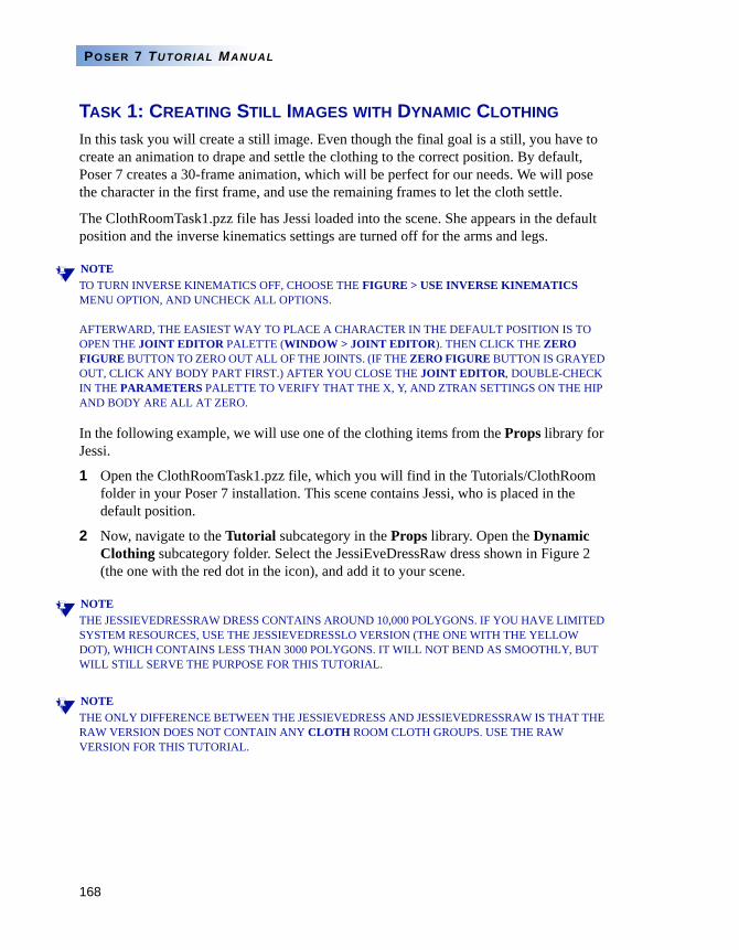
168
POSER 7 TUTORIAL MANUAL
TASK 1: CREATING STILL IMAGES WITH DYNAMIC CLOTHING
In this task you will create a still image. Even though the final goal is a still, you have to create an animation to drape and settle the clothing to the correct position. By default, Poser 7 creates a 30-frame animation, which will be perfect for our needs. We will pose the character in the first frame, and use the remaining frames to let the cloth settle.
The ClothRoomTask1.pzz file has Jessi loaded into the scene. She appears in the default position and the inverse kinematics settings are turned off for the arms and legs.
NOTETO TURN INVERSE KINEMATICS OFF, CHOOSE THE FIGURE > USE INVERSE KINEMATICS MENU OPTION, AND UNCHECK ALL OPTIONS.
AFTERWARD, THE EASIEST WAY TO PLACE A CHARACTER IN THE DEFAULT POSITION IS TO OPEN THE JOINT EDITOR PALETTE (WINDOW > JOINT EDITOR). THEN CLICK THE ZERO FIGURE BUTTON TO ZERO OUT ALL OF THE JOINTS. (IF THE ZERO FIGURE BUTTON IS GRAYED OUT, CLICK ANY BODY PART FIRST.) AFTER YOU CLOSE THE JOINT EDITOR, DOUBLE-CHECK IN THE PARAMETERS PALETTE TO VERIFY THAT THE X, Y, AND ZTRAN SETTINGS ON THE HIP AND BODY ARE ALL AT ZERO.
In the following example, we will use one of the clothing items from the Props library for Jessi.
1 Open the ClothRoomTask1.pzz file, which you will find in the Tutorials/ClothRoom folder in your Poser 7 installation. This scene contains Jessi, who is placed in the default position.
2 Now, navigate to the Tutorial subcategory in the Props library. Open the Dynamic Clothing subcategory folder. Select the JessiEveDressRaw dress shown in Figure 2 (the one with the red dot in the icon), and add it to your scene.
NOTETHE JESSIEVEDRESSRAW DRESS CONTAINS AROUND 10,000 POLYGONS. IF YOU HAVE LIMITED SYSTEM RESOURCES, USE THE JESSIEVEDRESSLO VERSION (THE ONE WITH THE YELLOW DOT), WHICH CONTAINS LESS THAN 3000 POLYGONS. IT WILL NOT BEND AS SMOOTHLY, BUT WILL STILL SERVE THE PURPOSE FOR THIS TUTORIAL.
NOTETHE ONLY DIFFERENCE BETWEEN THE JESSIEVEDRESS AND JESSIEVEDRESSRAW IS THAT THE RAW VERSION DOES NOT CONTAIN ANY CLOTH ROOM CLOTH GROUPS. USE THE RAW VERSION FOR THIS TUTORIAL.
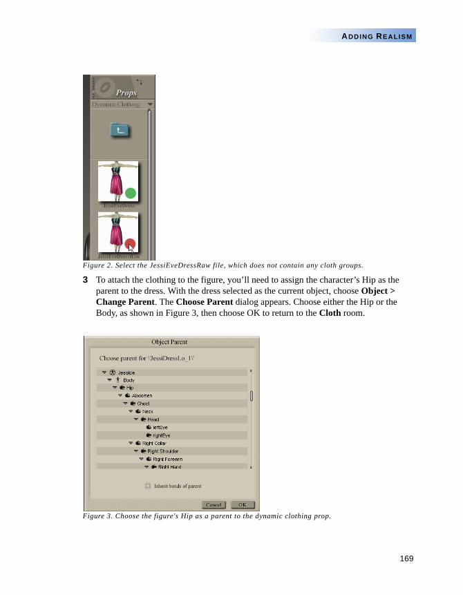
169
ADDING REALISM
Figure 2. Select the JessiEveDressRaw file, which does not contain any cloth groups.
3 To attach the clothing to the figure, you’ll need to assign the character’s Hip as the parent to the dress. With the dress selected as the current object, choose Object > Change Parent. The Choose Parent dialog appears. Choose either the Hip or the Body, as shown in Figure 3, then choose OK to return to the Cloth room.
Figure 3. Choose the figure's Hip as a parent to the dynamic clothing prop.
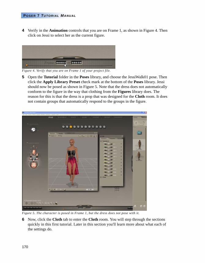
170
POSER 7 TUTORIAL MANUAL
4 Verify in the Animation controls that you are on Frame 1, as shown in Figure 4. Then click on Jessi to select her as the current figure.
Figure 4. Verify that you are on Frame 1 of your project file.
5 Open the Tutorial folder in the Poses library, and choose the JessiWalk01 pose. Then click the Apply Library Preset check mark at the bottom of the Poses library. Jessi should now be posed as shown in Figure 5. Note that the dress does not automatically conform to the figure in the way that clothing from the Figures library does. The reason for this is that the dress is a prop that was designed for the Cloth room. It does not contain groups that automatically respond to the groups in the figure.
Figure 5. The character is posed in Frame 1, but the dress does not pose with it.
6 Now, click the Cloth tab to enter the Cloth room. You will step through the sections quickly in this first tutorial. Later in this section you'll learn more about what each of the settings do.
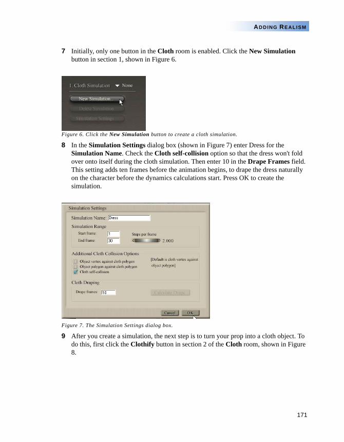
171
ADDING REALISM
7 Initially, only one button in the Cloth room is enabled. Click the New Simulation button in section 1, shown in Figure 6.
Figure 6. Click the New Simulation button to create a cloth simulation.
8 In the Simulation Settings dialog box (shown in Figure 7) enter Dress for the Simulation Name. Check the Cloth self-collision option so that the dress won't fold over onto itself during the cloth simulation. Then enter 10 in the Drape Frames field. This setting adds ten frames before the animation begins, to drape the dress naturally on the character before the dynamics calculations start. Press OK to create the simulation.
Figure 7. The Simulation Settings dialog box.
9 After you create a simulation, the next step is to turn your prop into a cloth object. To do this, first click the Clothify button in section 2 of the Cloth room, shown in Figure 8.
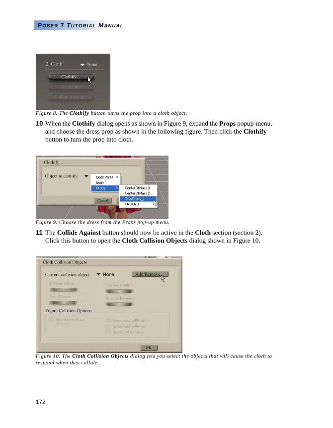
172
POSER 7 TUTORIAL MANUAL
Figure 8. The Clothify button turns the prop into a cloth object.
10 When the Clothify dialog opens as shown in Figure 9, expand the Props popup-menu, and choose the dress prop as shown in the following figure. Then click the Clothify button to turn the prop into cloth.
Figure 9. Choose the dress from the Props pop-up menu.
11 The Collide Against button should now be active in the Cloth section (section 2). Click this button to open the Cloth Collision Objects dialog shown in Figure 10.
Figure 10. The Cloth Collision Objects dialog lets you select the objects that will cause the cloth to respond when they collide.
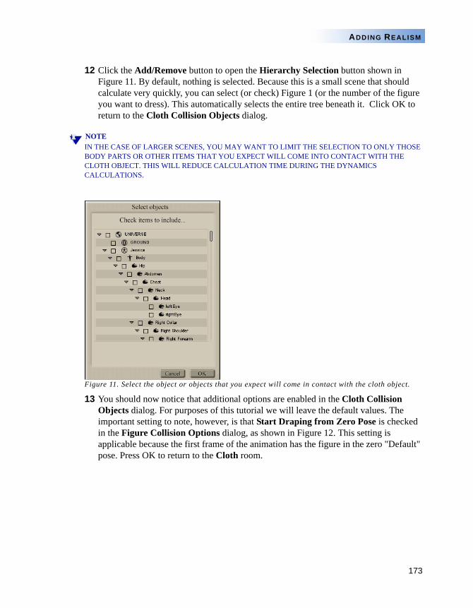
173
ADDING REALISM
12 Click the Add/Remove button to open the Hierarchy Selection button shown in Figure 11. By default, nothing is selected. Because this is a small scene that should calculate very quickly, you can select (or check) Figure 1 (or the number of the figure you want to dress). This automatically selects the entire tree beneath it. Click OK to return to the Cloth Collision Objects dialog.
NOTEIN THE CASE OF LARGER SCENES, YOU MAY WANT TO LIMIT THE SELECTION TO ONLY THOSE BODY PARTS OR OTHER ITEMS THAT YOU EXPECT WILL COME INTO CONTACT WITH THE CLOTH OBJECT. THIS WILL REDUCE CALCULATION TIME DURING THE DYNAMICS CALCULATIONS.
Figure 11. Select the object or objects that you expect will come in contact with the cloth object.
13 You should now notice that additional options are enabled in the Cloth Collision Objects dialog. For purposes of this tutorial we will leave the default values. The important setting to note, however, is that Start Draping from Zero Pose is checked in the Figure Collision Options dialog, as shown in Figure 12. This setting is applicable because the first frame of the animation has the figure in the zero "Default" pose. Press OK to return to the Cloth room.
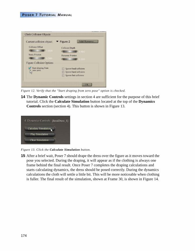
174
POSER 7 TUTORIAL MANUAL
Figure 12. Verify that the "Start draping from zero pose" option is checked.
14 The Dynamic Controls settings in section 4 are sufficient for the purpose of this brief tutorial. Click the Calculate Simulation button located at the top of the Dynamics Controls section (section 4). This button is shown in Figure 13.
Figure 13. Click the Calculate Simulation button.
15 After a brief wait, Poser 7 should drape the dress over the figure as it moves toward the pose you selected. During the draping, it will appear as if the clothing is always one frame behind the final result. Once Poser 7 completes the draping calculations and starts calculating dynamics, the dress should be posed correctly. During the dynamics calculations the cloth will settle a little bit. This will be more noticeable when clothing is fuller. The final result of the simulation, shown at Frame 30, is shown in Figure 14.
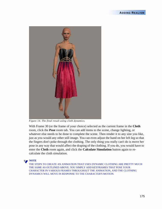
175
ADDING REALISM
Figure 14. The final result using cloth dynamics.
With Frame 30 (or the frame of your choice) selected as the current frame in the Cloth room, click the Pose room tab. You can add items to the scene, change lighting, or whatever else needs to be done to complete the scene. Then render it to any size you like, just as you would any other still image. You can even adjust the hand on her left leg so that the fingers don't poke through the clothing. The only thing you really can't do is move her pose in any way that would affect the draping of the clothing. If you do, you would have to enter the Cloth room again, and click the Calculate Simulation button again to re-calculate the cloth simulation.
NOTETHE STEPS TO CREATE AN ANIMATION THAT USES DYNAMIC CLOTHING ARE PRETTY MUCH THE SAME AS OUTLINED ABOVE. YOU SIMPLY ADD KEYFRAMES THAT POSE YOUR CHARACTER IN VARIOUS FRAMES THROUGHOUT THE ANIMATION, AND THE CLOTHING DYNAMICS WILL MOVE IN RESPONSE TO THE CHARACTER'S MOTION.
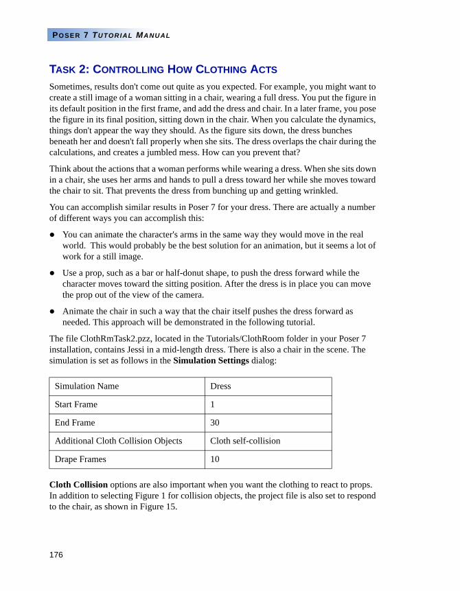
176
POSER 7 TUTORIAL MANUAL
TASK 2: CONTROLLING HOW CLOTHING ACTS
Sometimes, results don't come out quite as you expected. For example, you might want to create a still image of a woman sitting in a chair, wearing a full dress. You put the figure in its default position in the first frame, and add the dress and chair. In a later frame, you pose the figure in its final position, sitting down in the chair. When you calculate the dynamics, things don't appear the way they should. As the figure sits down, the dress bunches beneath her and doesn't fall properly when she sits. The dress overlaps the chair during the calculations, and creates a jumbled mess. How can you prevent that?
Think about the actions that a woman performs while wearing a dress. When she sits down in a chair, she uses her arms and hands to pull a dress toward her while she moves toward the chair to sit. That prevents the dress from bunching up and getting wrinkled.
You can accomplish similar results in Poser 7 for your dress. There are actually a number of different ways you can accomplish this:
You can animate the character's arms in the same way they would move in the real world. This would probably be the best solution for an animation, but it seems a lot of work for a still image.
Use a prop, such as a bar or half-donut shape, to push the dress forward while the character moves toward the sitting position. After the dress is in place you can move the prop out of the view of the camera.
Animate the chair in such a way that the chair itself pushes the dress forward as needed. This approach will be demonstrated in the following tutorial.
The file ClothRmTask2.pzz, located in the Tutorials/ClothRoom folder in your Poser 7 installation, contains Jessi in a mid-length dress. There is also a chair in the scene. The simulation is set as follows in the Simulation Settings dialog:
Cloth Collision options are also important when you want the clothing to react to props. In addition to selecting Figure 1 for collision objects, the project file is also set to respond to the chair, as shown in Figure 15.
Simulation Name Dress
Start Frame 1
End Frame 30
Additional Cloth Collision Objects Cloth self-collision
Drape Frames 10
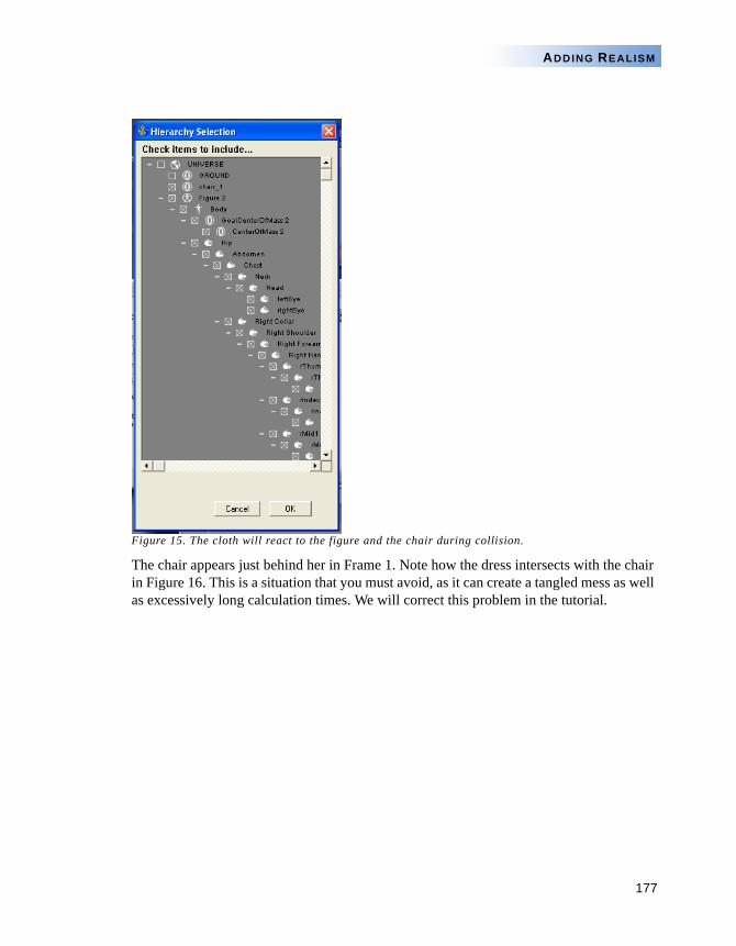
177
ADDING REALISM
Figure 15. The cloth will react to the figure and the chair during collision.
The chair appears just behind her in Frame 1. Note how the dress intersects with the chair in Figure 16. This is a situation that you must avoid, as it can create a tangled mess as well as excessively long calculation times. We will correct this problem in the tutorial.
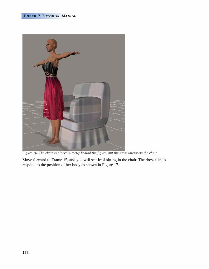
178
POSER 7 TUTORIAL MANUAL
Figure 16. The chair is placed directly behind the figure, but the dress intersects the chair.
Move forward to Frame 15, and you will see Jessi sitting in the chair. The dress tilts to respond to the position of her body as shown in Figure 17.
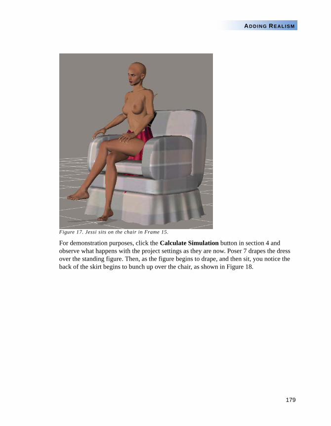
179
ADDING REALISM
Figure 17. Jessi sits on the chair in Frame 15.
For demonstration purposes, click the Calculate Simulation button in section 4 and observe what happens with the project settings as they are now. Poser 7 drapes the dress over the standing figure. Then, as the figure begins to drape, and then sit, you notice the back of the skirt begins to bunch up over the chair, as shown in Figure 18.
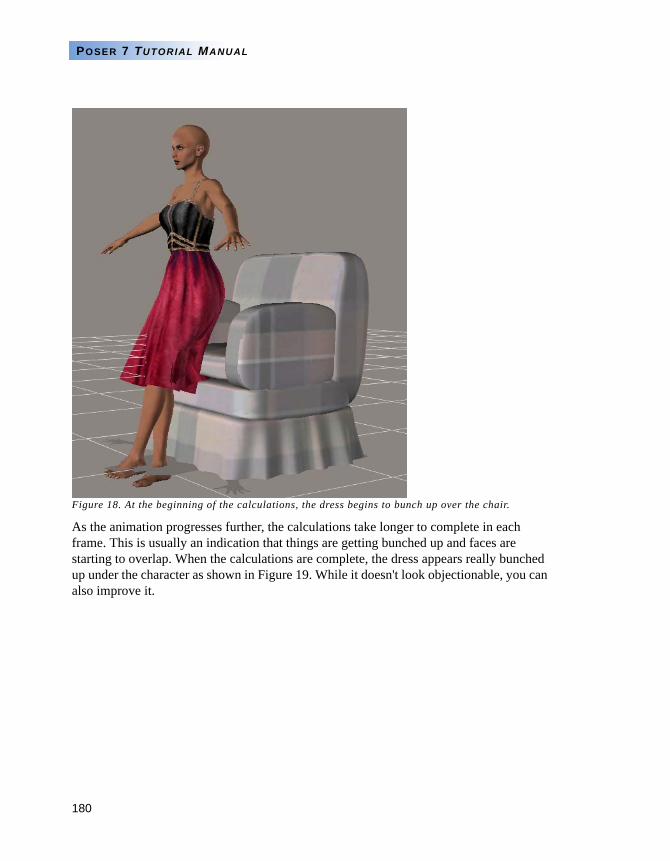
180
POSER 7 TUTORIAL MANUAL
Figure 18. At the beginning of the calculations, the dress begins to bunch up over the chair.
As the animation progresses further, the calculations take longer to complete in each frame. This is usually an indication that things are getting bunched up and faces are starting to overlap. When the calculations are complete, the dress appears really bunched up under the character as shown in Figure 19. While it doesn't look objectionable, you can also improve it.
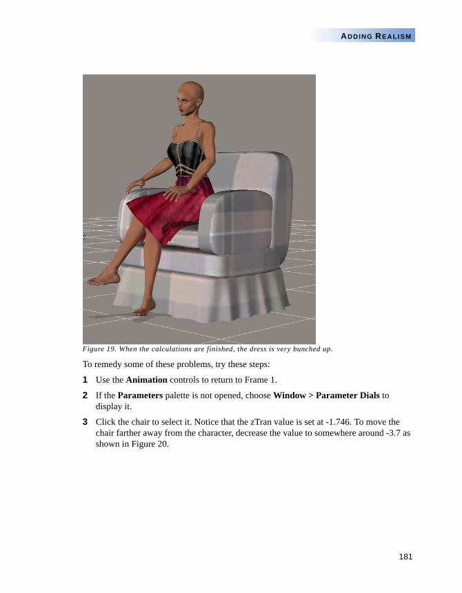
181
ADDING REALISM
Figure 19. When the calculations are finished, the dress is very bunched up.
To remedy some of these problems, try these steps:
1 Use the Animation controls to return to Frame 1.
2 If the Parameters palette is not opened, choose Window > Parameter Dials to display it.
3 Click the chair to select it. Notice that the zTran value is set at -1.746. To move the chair farther away from the character, decrease the value to somewhere around -3.7 as shown in Figure 20.
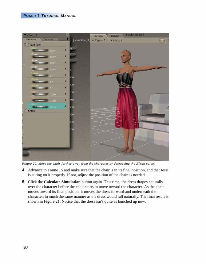
182
POSER 7 TUTORIAL MANUAL
Figure 20. Move the chair farther away from the character by decreasing the ZTran value.
4 Advance to Frame 15 and make sure that the chair is in its final position, and that Jessi is sitting on it properly. If not, adjust the position of the chair as needed.
5 Click the Calculate Simulation button again. This time, the dress drapes naturally over the character before the chair starts to move toward the character. As the chair moves toward its final position, it moves the dress forward and underneath the character, in much the same manner as the dress would fall naturally. The final result is shown in Figure 21. Notice that the dress isn’t quite as bunched up now.
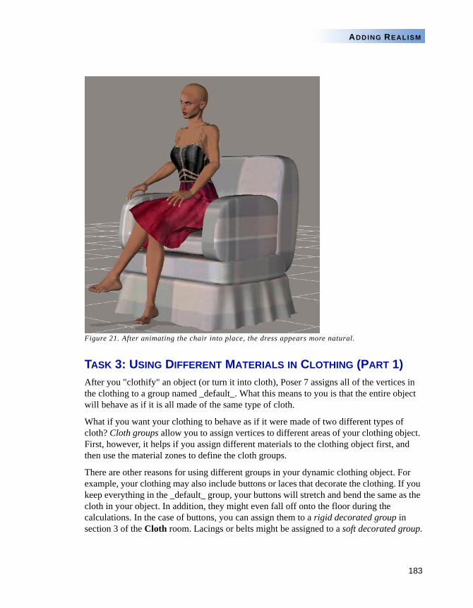
183
ADDING REALISM
Figure 21. After animating the chair into place, the dress appears more natural.
TASK 3: USING DIFFERENT MATERIALS IN CLOTHING (PART 1)After you "clothify" an object (or turn it into cloth), Poser 7 assigns all of the vertices in the clothing to a group named _default_. What this means to you is that the entire object will behave as if it is all made of the same type of cloth.
What if you want your clothing to behave as if it were made of two different types of cloth? Cloth groups allow you to assign vertices to different areas of your clothing object. First, however, it helps if you assign different materials to the clothing object first, and then use the material zones to define the cloth groups.
There are other reasons for using different groups in your dynamic clothing object. For example, your clothing may also include buttons or laces that decorate the clothing. If you keep everything in the _default_ group, your buttons will stretch and bend the same as the cloth in your object. In addition, they might even fall off onto the floor during the calculations. In the case of buttons, you can assign them to a rigid decorated group in section 3 of the Cloth room. Lacings or belts might be assigned to a soft decorated group.
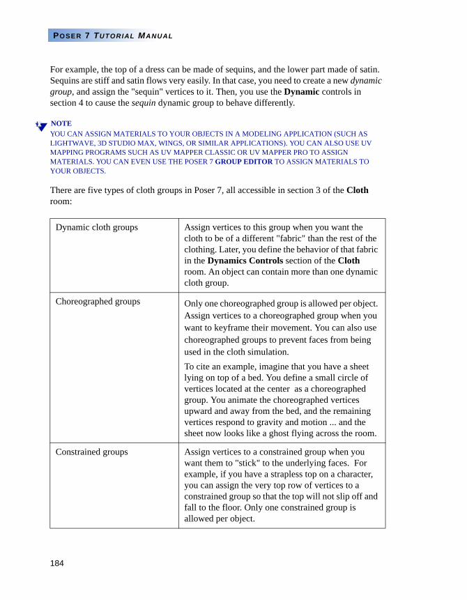
184
POSER 7 TUTORIAL MANUAL
For example, the top of a dress can be made of sequins, and the lower part made of satin. Sequins are stiff and satin flows very easily. In that case, you need to create a new dynamic group, and assign the "sequin" vertices to it. Then, you use the Dynamic controls in section 4 to cause the sequin dynamic group to behave differently.
NOTEYOU CAN ASSIGN MATERIALS TO YOUR OBJECTS IN A MODELING APPLICATION (SUCH AS LIGHTWAVE, 3D STUDIO MAX, WINGS, OR SIMILAR APPLICATIONS). YOU CAN ALSO USE UV MAPPING PROGRAMS SUCH AS UV MAPPER CLASSIC OR UV MAPPER PRO TO ASSIGN MATERIALS. YOU CAN EVEN USE THE POSER 7 GROUP EDITOR TO ASSIGN MATERIALS TO YOUR OBJECTS.
There are five types of cloth groups in Poser 7, all accessible in section 3 of the Cloth room:
Dynamic cloth groups Assign vertices to this group when you want the cloth to be of a different "fabric" than the rest of the clothing. Later, you define the behavior of that fabric in the Dynamics Controls section of the Cloth room. An object can contain more than one dynamic cloth group.
Choreographed groups Only one choreographed group is allowed per object. Assign vertices to a choreographed group when you want to keyframe their movement. You can also use choreographed groups to prevent faces from being used in the cloth simulation.To cite an example, imagine that you have a sheet lying on top of a bed. You define a small circle of vertices located at the center as a choreographed group. You animate the choreographed vertices upward and away from the bed, and the remaining vertices respond to gravity and motion ... and the sheet now looks like a ghost flying across the room.
Constrained groups Assign vertices to a constrained group when you want them to "stick" to the underlying faces. For example, if you have a strapless top on a character, you can assign the very top row of vertices to a constrained group so that the top will not slip off and fall to the floor. Only one constrained group is allowed per object.
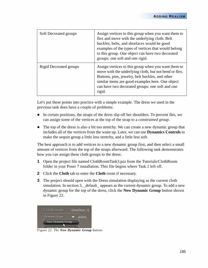
185
ADDING REALISM
Let's put these points into practice with a simple example. The dress we used in the previous task does have a couple of problems:
In certain positions, the straps of the dress slip off her shoulders. To prevent this, we can assign some of the vertices at the top of the strap to a constrained group.
The top of the dress is also a bit too stretchy. We can create a new dynamic group that includes all of the vertices from the waist up. Later, we can use Dynamics Controls to make the sequin group a little less stretchy, and a little less soft.
The best approach is to add vertices to a new dynamic group first, and then select a small amount of vertices from the top of the straps afterward. The following task demonstrates how you can assign these cloth groups to the dress:
1 Open the project file named ClothRoomTask3.pzz from the Tutorials/ClothRoom folder in your Poser 7 installation. This file begins where Task 2 left off.
2 Click the Cloth tab to enter the Cloth room if necessary.
3 The project should open with the Dress simulation displaying as the current cloth simulation. In section 3, _default_ appears as the current dynamic group. To add a new dynamic group for the top of the dress, click the New Dynamic Group button shown in Figure 22.
Figure 22. The New Dynamic Group button.
Soft Decorated groups Assign vertices to this group when you want them to flex and move with the underlying cloth. Belt buckles, belts, and shoelaces would be good examples of the types of vertices that would belong to this group. One object can have two decorated groups: one soft and one rigid.
Rigid Decorated groups Assign vertices to this group when you want them to move with the underlying cloth, but not bend or flex. Buttons, pins, jewelry, belt buckles, and other similar items are good examples here. One object can have two decorated groups: one soft and one rigid.
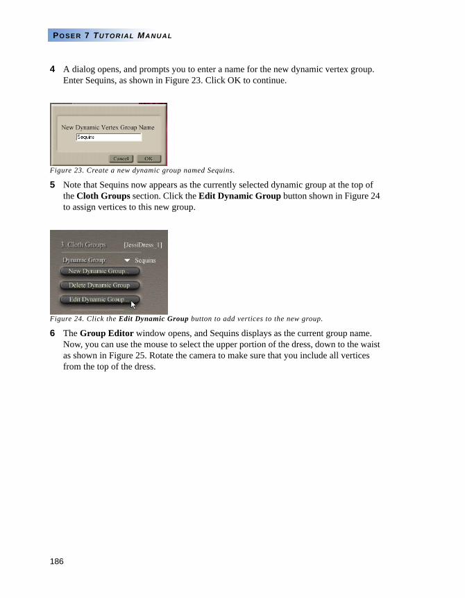
186
POSER 7 TUTORIAL MANUAL
4 A dialog opens, and prompts you to enter a name for the new dynamic vertex group. Enter Sequins, as shown in Figure 23. Click OK to continue.
Figure 23. Create a new dynamic group named Sequins.
5 Note that Sequins now appears as the currently selected dynamic group at the top of the Cloth Groups section. Click the Edit Dynamic Group button shown in Figure 24 to assign vertices to this new group.
Figure 24. Click the Edit Dynamic Group button to add vertices to the new group.
6 The Group Editor window opens, and Sequins displays as the current group name. Now, you can use the mouse to select the upper portion of the dress, down to the waist as shown in Figure 25. Rotate the camera to make sure that you include all vertices from the top of the dress.
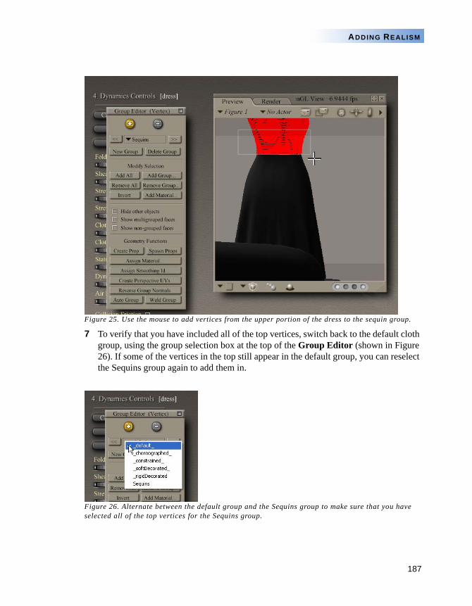
187
ADDING REALISM
Figure 25. Use the mouse to add vertices from the upper portion of the dress to the sequin group.
7 To verify that you have included all of the top vertices, switch back to the default cloth group, using the group selection box at the top of the Group Editor (shown in Figure 26). If some of the vertices in the top still appear in the default group, you can reselect the Sequins group again to add them in.
Figure 26. Alternate between the default group and the Sequins group to make sure that you have selected all of the top vertices for the Sequins group.
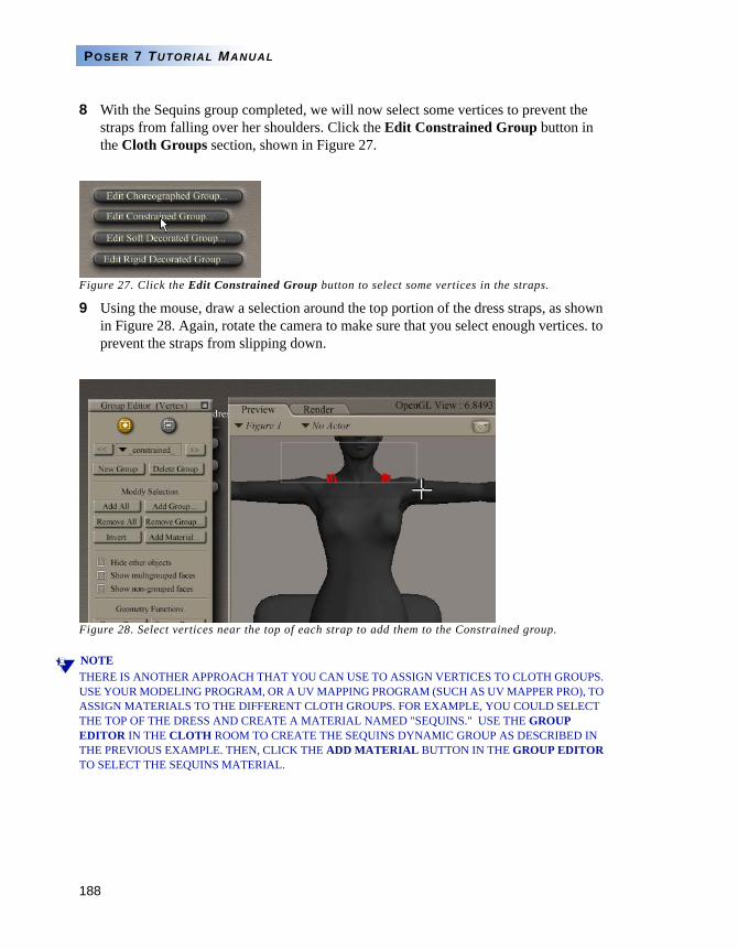
188
POSER 7 TUTORIAL MANUAL
8 With the Sequins group completed, we will now select some vertices to prevent the straps from falling over her shoulders. Click the Edit Constrained Group button in the Cloth Groups section, shown in Figure 27.
Figure 27. Click the Edit Constrained Group button to select some vertices in the straps.
9 Using the mouse, draw a selection around the top portion of the dress straps, as shown in Figure 28. Again, rotate the camera to make sure that you select enough vertices. to prevent the straps from slipping down.
Figure 28. Select vertices near the top of each strap to add them to the Constrained group.
NOTETHERE IS ANOTHER APPROACH THAT YOU CAN USE TO ASSIGN VERTICES TO CLOTH GROUPS. USE YOUR MODELING PROGRAM, OR A UV MAPPING PROGRAM (SUCH AS UV MAPPER PRO), TO ASSIGN MATERIALS TO THE DIFFERENT CLOTH GROUPS. FOR EXAMPLE, YOU COULD SELECT THE TOP OF THE DRESS AND CREATE A MATERIAL NAMED "SEQUINS." USE THE GROUP EDITOR IN THE CLOTH ROOM TO CREATE THE SEQUINS DYNAMIC GROUP AS DESCRIBED IN THE PREVIOUS EXAMPLE. THEN, CLICK THE ADD MATERIAL BUTTON IN THE GROUP EDITOR TO SELECT THE SEQUINS MATERIAL.
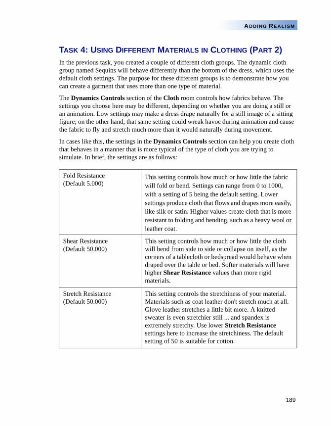
189
ADDING REALISM
TASK 4: USING DIFFERENT MATERIALS IN CLOTHING (PART 2)In the previous task, you created a couple of different cloth groups. The dynamic cloth group named Sequins will behave differently than the bottom of the dress, which uses the default cloth settings. The purpose for these different groups is to demonstrate how you can create a garment that uses more than one type of material.
The Dynamics Controls section of the Cloth room controls how fabrics behave. The settings you choose here may be different, depending on whether you are doing a still or an animation. Low settings may make a dress drape naturally for a still image of a sitting figure; on the other hand, that same setting could wreak havoc during animation and cause the fabric to fly and stretch much more than it would naturally during movement.
In cases like this, the settings in the Dynamics Controls section can help you create cloth that behaves in a manner that is more typical of the type of cloth you are trying to simulate. In brief, the settings are as follows:
Fold Resistance (Default 5.000)
This setting controls how much or how little the fabric will fold or bend. Settings can range from 0 to 1000, with a setting of 5 being the default setting. Lower settings produce cloth that flows and drapes more easily, like silk or satin. Higher values create cloth that is more resistant to folding and bending, such as a heavy wool or leather coat.
Shear Resistance (Default 50.000)
This setting controls how much or how little the cloth will bend from side to side or collapse on itself, as the corners of a tablecloth or bedspread would behave when draped over the table or bed. Softer materials will have higher Shear Resistance values than more rigid materials.
Stretch Resistance (Default 50.000)
This setting controls the stretchiness of your material. Materials such as coat leather don't stretch much at all. Glove leather stretches a little bit more. A knitted sweater is even stretchier still ... and spandex is extremely stretchy. Use lower Stretch Resistance settings here to increase the stretchiness. The default setting of 50 is suitable for cotton.
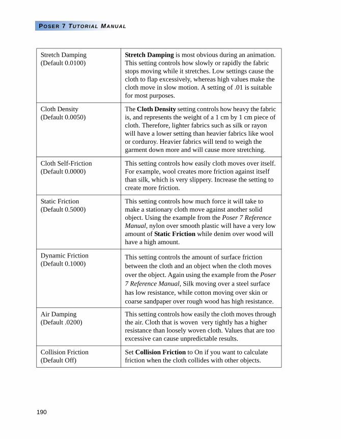
190
POSER 7 TUTORIAL MANUAL
Stretch Damping (Default 0.0100)
Stretch Damping is most obvious during an animation. This setting controls how slowly or rapidly the fabric stops moving while it stretches. Low settings cause the cloth to flap excessively, whereas high values make the cloth move in slow motion. A setting of .01 is suitable for most purposes.
Cloth Density (Default 0.0050)
The Cloth Density setting controls how heavy the fabric is, and represents the weight of a 1 cm by 1 cm piece of cloth. Therefore, lighter fabrics such as silk or rayon will have a lower setting than heavier fabrics like wool or corduroy. Heavier fabrics will tend to weigh the garment down more and will cause more stretching.
Cloth Self-Friction (Default 0.0000)
This setting controls how easily cloth moves over itself. For example, wool creates more friction against itself than silk, which is very slippery. Increase the setting to create more friction.
Static Friction (Default 0.5000)
This setting controls how much force it will take to make a stationary cloth move against another solid object. Using the example from the Poser 7 Reference Manual, nylon over smooth plastic will have a very low amount of Static Friction while denim over wood will have a high amount.
Dynamic Friction(Default 0.1000)
This setting controls the amount of surface friction between the cloth and an object when the cloth moves over the object. Again using the example from the Poser 7 Reference Manual, Silk moving over a steel surface has low resistance, while cotton moving over skin or coarse sandpaper over rough wood has high resistance.
Air Damping (Default .0200)
This setting controls how easily the cloth moves through the air. Cloth that is woven very tightly has a higher resistance than loosely woven cloth. Values that are too excessive can cause unpredictable results.
Collision Friction (Default Off)
Set Collision Friction to On if you want to calculate friction when the cloth collides with other objects.
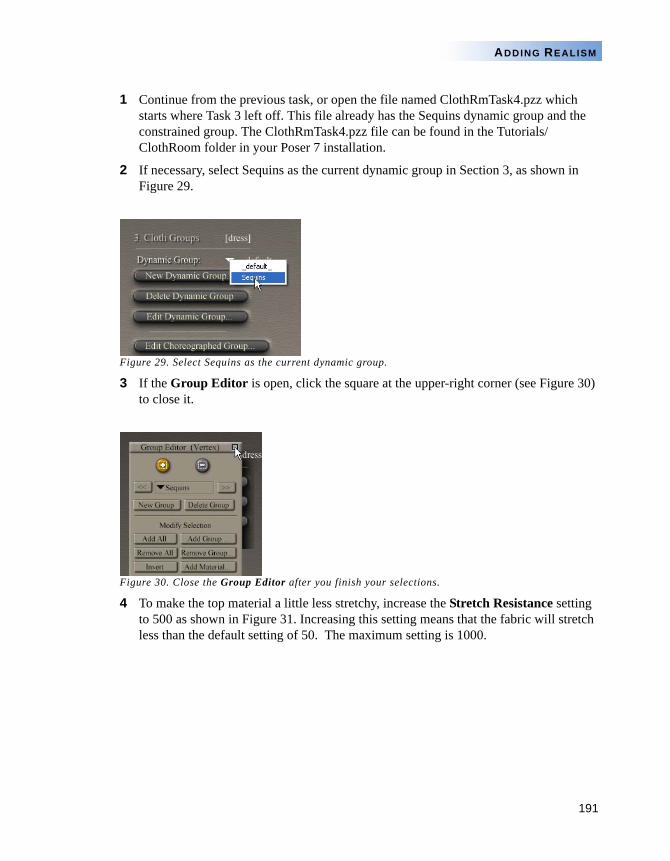
191
ADDING REALISM
1 Continue from the previous task, or open the file named ClothRmTask4.pzz which starts where Task 3 left off. This file already has the Sequins dynamic group and the constrained group. The ClothRmTask4.pzz file can be found in the Tutorials/ClothRoom folder in your Poser 7 installation.
2 If necessary, select Sequins as the current dynamic group in Section 3, as shown in Figure 29.
Figure 29. Select Sequins as the current dynamic group.
3 If the Group Editor is open, click the square at the upper-right corner (see Figure 30) to close it.
Figure 30. Close the Group Editor after you finish your selections.
4 To make the top material a little less stretchy, increase the Stretch Resistance setting to 500 as shown in Figure 31. Increasing this setting means that the fabric will stretch less than the default setting of 50. The maximum setting is 1000.
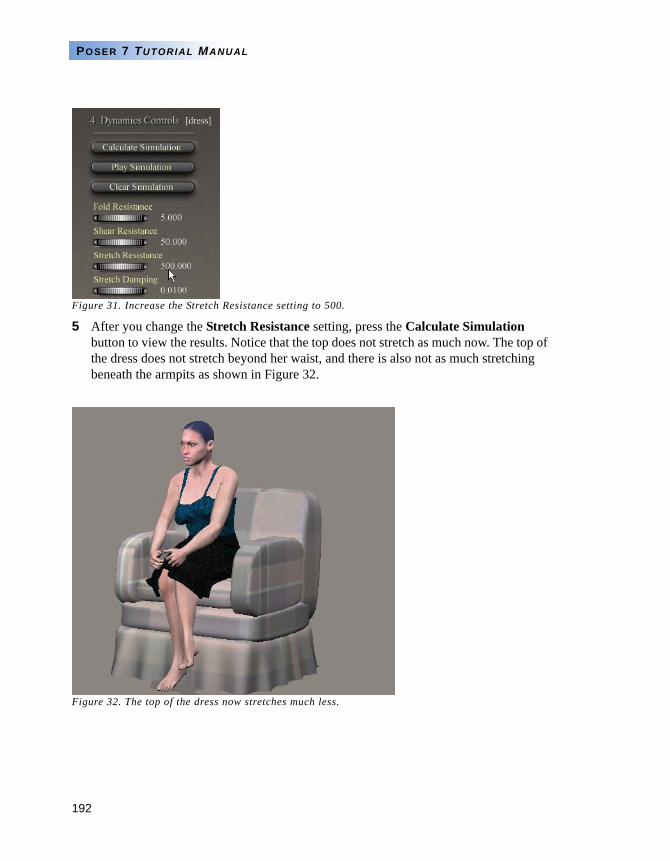
192
POSER 7 TUTORIAL MANUAL
Figure 31. Increase the Stretch Resistance setting to 500.
5 After you change the Stretch Resistance setting, press the Calculate Simulation button to view the results. Notice that the top does not stretch as much now. The top of the dress does not stretch beyond her waist, and there is also not as much stretching beneath the armpits as shown in Figure 32.
Figure 32. The top of the dress now stretches much less.
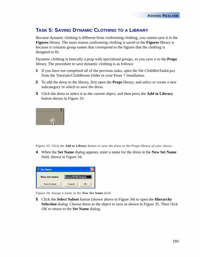
193
ADDING REALISM
TASK 5: SAVING DYNAMIC CLOTHING TO A LIBRARY
Because dynamic clothing is different from conforming clothing, you cannot save it to the Figures library. The main reason conforming clothing is saved in the Figures library is because it contains group names that correspond to the figures that the clothing is designed to fit.
Dynamic clothing is basically a prop with specialized groups, so you save it to the Props library. The procedure to save dynamic clothing is as follows:
1 If you have not completed all of the previous tasks, open the file ClothRmTask4.pzz from the Tutorials/ClothRoom folder in your Poser 7 installation.
2 To add the dress to the library, first open the Props library, and select or create a new subcategory in which to save the dress.
3 Click the dress to select it as the current object, and then press the Add to Library button shown in Figure 33.
Figure 33. Click the Add to Library button to save the dress to the Props library of your choice.
4 When the Set Name dialog appears, enter a name for the dress in the New Set Name field, shown in Figure 34.
Figure 34. Assign a name in the New Set Name field.
5 Click the Select Subset button (shown above in Figure 34) to open the Hierarchy Selection dialog. Choose dress as the object to save as shown in Figure 35. Then click OK to return to the Set Name dialog.
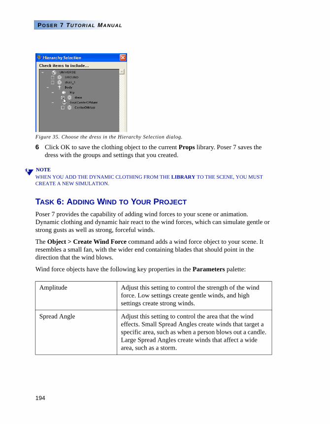
194
POSER 7 TUTORIAL MANUAL
Figure 35. Choose the dress in the Hierarchy Selection dialog.
6 Click OK to save the clothing object to the current Props library. Poser 7 saves the dress with the groups and settings that you created.
NOTEWHEN YOU ADD THE DYNAMIC CLOTHING FROM THE LIBRARY TO THE SCENE, YOU MUST CREATE A NEW SIMULATION.
TASK 6: ADDING WIND TO YOUR PROJECT
Poser 7 provides the capability of adding wind forces to your scene or animation. Dynamic clothing and dynamic hair react to the wind forces, which can simulate gentle or strong gusts as well as strong, forceful winds.
The Object > Create Wind Force command adds a wind force object to your scene. It resembles a small fan, with the wider end containing blades that should point in the direction that the wind blows.
Wind force objects have the following key properties in the Parameters palette:
Amplitude Adjust this setting to control the strength of the wind force. Low settings create gentle winds, and high settings create strong winds.
Spread Angle Adjust this setting to control the area that the wind effects. Small Spread Angles create winds that target a specific area, such as when a person blows out a candle. Large Spread Angles create winds that affect a wide area, such as a storm.
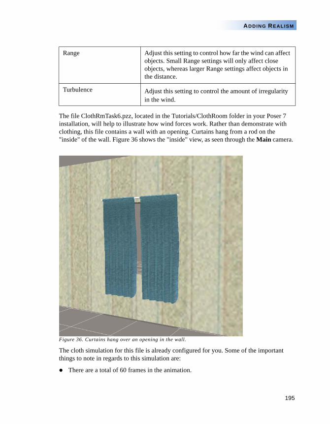
195
ADDING REALISM
The file ClothRmTask6.pzz, located in the Tutorials/ClothRoom folder in your Poser 7 installation, will help to illustrate how wind forces work. Rather than demonstrate with clothing, this file contains a wall with an opening. Curtains hang from a rod on the "inside" of the wall. Figure 36 shows the "inside" view, as seen through the Main camera.
Figure 36. Curtains hang over an opening in the wall.
The cloth simulation for this file is already configured for you. Some of the important things to note in regards to this simulation are:
There are a total of 60 frames in the animation.
Range Adjust this setting to control how far the wind can affect objects. Small Range settings will only affect close objects, whereas larger Range settings affect objects in the distance.
Turbulence Adjust this setting to control the amount of irregularity in the wind.
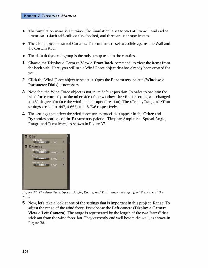
196
POSER 7 TUTORIAL MANUAL
The Simulation name is Curtains. The simulation is set to start at Frame 1 and end at Frame 60. Cloth self-collision is checked, and there are 10 drape frames.
The Cloth object is named Curtains. The curtains are set to collide against the Wall and the Curtain Rod.
The default dynamic group is the only group used in the curtains.
1 Choose the Display > Camera View > From Back command, to view the items from the back side. Here, you will see a Wind Force object that has already been created for you.
2 Click the Wind Force object to select it. Open the Parameters palette (Window > Parameter Dials) if necessary.
3 Note that the Wind Force object is not in its default position. In order to position the wind force correctly on the other side of the window, the yRotate setting was changed to 180 degrees (to face the wind in the proper direction). The xTran, yTran, and zTran settings are set to .447, 4.662, and -5.736 respectively.
4 The settings that affect the wind force (or its forcefield) appear in the Other and Dynamics portions of the Parameters palette. They are Amplitude, Spread Angle, Range, and Turbulence, as shown in Figure 37.
Figure 37. The Amplitude, Spread Angle, Range, and Turbulence settings affect the force of the wind.
5 Now, let's take a look at one of the settings that is important in this project: Range. To adjust the range of the wind force, first choose the Left camera (Display > Camera View > Left Camera). The range is represented by the length of the two "arms" that stick out from the wind force fan. They currently end well before the wall, as shown in Figure 38.
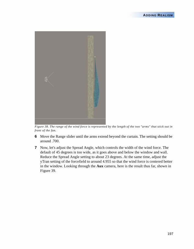
197
ADDING REALISM
Figure 38. The range of the wind force is represented by the length of the two "arms" that stick out in front of the fan.
6 Move the Range slider until the arms extend beyond the curtain. The setting should be around .700.
7 Now, let's adjust the Spread Angle, which controls the width of the wind force. The default of 45 degrees is too wide, as it goes above and below the window and wall. Reduce the Spread Angle setting to about 23 degrees. At the same time, adjust the yTran setting of the forcefield to around 4.955 so that the wind force is centered better in the window. Looking through the Aux camera, here is the result thus far, shown in Figure 39.
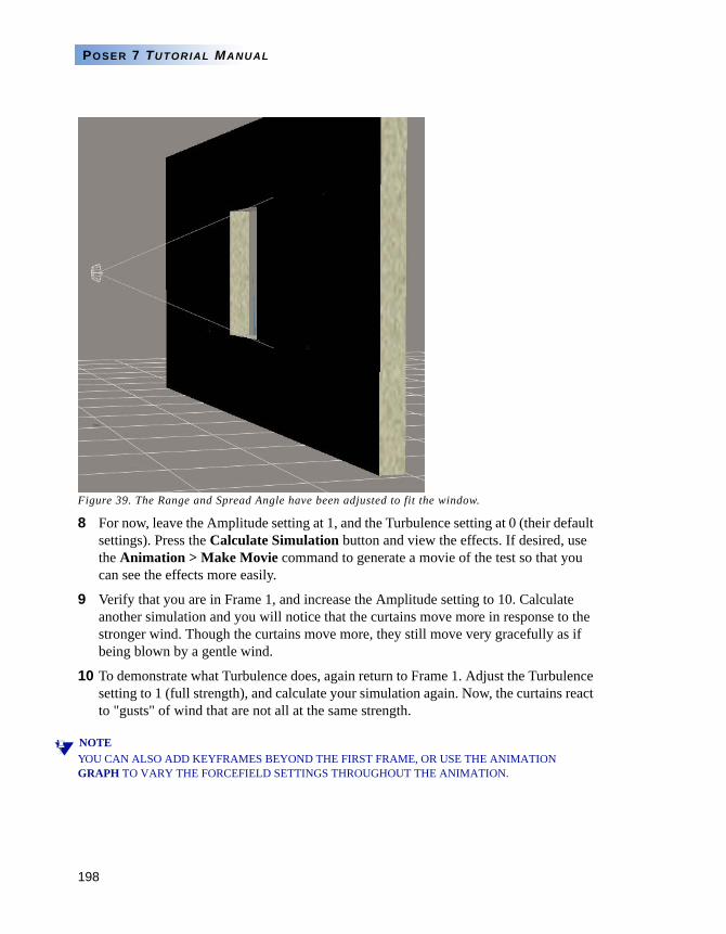
198
POSER 7 TUTORIAL MANUAL
Figure 39. The Range and Spread Angle have been adjusted to fit the window.
8 For now, leave the Amplitude setting at 1, and the Turbulence setting at 0 (their default settings). Press the Calculate Simulation button and view the effects. If desired, use the Animation > Make Movie command to generate a movie of the test so that you can see the effects more easily.
9 Verify that you are in Frame 1, and increase the Amplitude setting to 10. Calculate another simulation and you will notice that the curtains move more in response to the stronger wind. Though the curtains move more, they still move very gracefully as if being blown by a gentle wind.
10 To demonstrate what Turbulence does, again return to Frame 1. Adjust the Turbulence setting to 1 (full strength), and calculate your simulation again. Now, the curtains react to "gusts" of wind that are not all at the same strength.
NOTEYOU CAN ALSO ADD KEYFRAMES BEYOND THE FIRST FRAME, OR USE THE ANIMATION GRAPH TO VARY THE FORCEFIELD SETTINGS THROUGHOUT THE ANIMATION.
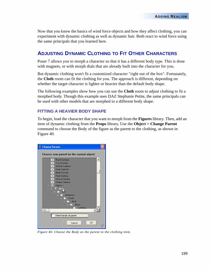
199
ADDING REALISM
Now that you know the basics of wind force objects and how they affect clothing, you can experiment with dynamic clothing as well as dynamic hair. Both react to wind force using the same principals that you learned here.
ADJUSTING DYNAMIC CLOTHING TO FIT OTHER CHARACTERS
Poser 7 allows you to morph a character so that it has a different body type. This is done with magnets, or with morph dials that are already built into the character for you.
But dynamic clothing won't fit a customized character "right out of the box". Fortunately, the Cloth room can fit the clothing for you. The approach is different, depending on whether the target character is lighter or heavier than the default body shape.
The following examples show how you can use the Cloth room to adjust clothing to fit a morphed body. Though this example uses DAZ Stephanie Petite, the same principals can be used with other models that are morphed to a different body shape.
FITTING A HEAVIER BODY SHAPE
To begin, load the character that you want to morph from the Figures library. Then, add an item of dynamic clothing from the Props library. Use the Object > Change Parent command to choose the Body of the figure as the parent to the clothing, as shown in Figure 40.
Figure 40. Choose the Body as the parent to the clothing item.
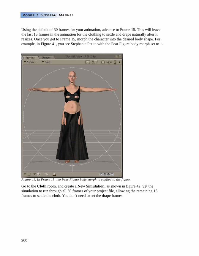
200
POSER 7 TUTORIAL MANUAL
Using the default of 30 frames for your animation, advance to Frame 15. This will leave the last 15 frames in the animation for the clothing to settle and drape naturally after it resizes. Once you get to Frame 15, morph the character into the desired body shape. For example, in Figure 41, you see Stephanie Petite with the Pear Figure body morph set to 1.
Figure 41. In Frame 15, the Pear Figure body morph is applied to the figure.
Go to the Cloth room, and create a New Simulation, as shown in figure 42. Set the simulation to run through all 30 frames of your project file, allowing the remaining 15 frames to settle the cloth. You don't need to set the drape frames.
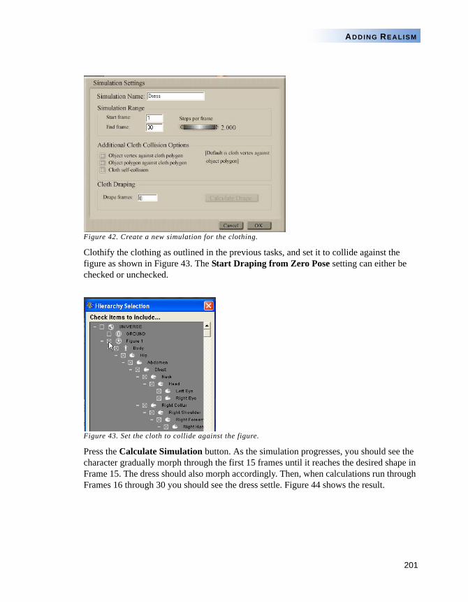
201
ADDING REALISM
Figure 42. Create a new simulation for the clothing.
Clothify the clothing as outlined in the previous tasks, and set it to collide against the figure as shown in Figure 43. The Start Draping from Zero Pose setting can either be checked or unchecked.
Figure 43. Set the cloth to collide against the figure.
Press the Calculate Simulation button. As the simulation progresses, you should see the character gradually morph through the first 15 frames until it reaches the desired shape in Frame 15. The dress should also morph accordingly. Then, when calculations run through Frames 16 through 30 you should see the dress settle. Figure 44 shows the result.
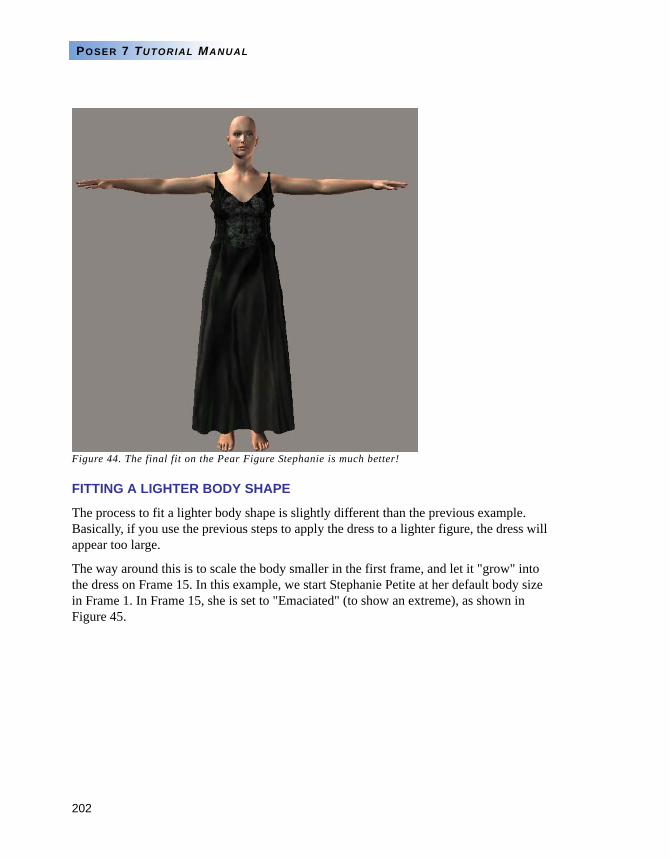
202
POSER 7 TUTORIAL MANUAL
Figure 44. The final fit on the Pear Figure Stephanie is much better!
FITTING A LIGHTER BODY SHAPE
The process to fit a lighter body shape is slightly different than the previous example. Basically, if you use the previous steps to apply the dress to a lighter figure, the dress will appear too large.
The way around this is to scale the body smaller in the first frame, and let it "grow" into the dress on Frame 15. In this example, we start Stephanie Petite at her default body size in Frame 1. In Frame 15, she is set to "Emaciated" (to show an extreme), as shown in Figure 45.
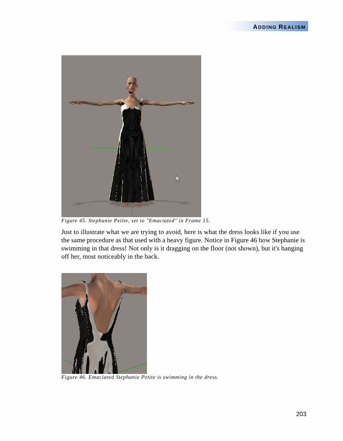
203
ADDING REALISM
Figure 45. Stephanie Petite, set to "Emaciated" in Frame 15.
Just to illustrate what we are trying to avoid, here is what the dress looks like if you use the same procedure as that used with a heavy figure. Notice in Figure 46 how Stephanie is swimming in that dress! Not only is it dragging on the floor (not shown), but it's hanging off her, most noticeably in the back.
Figure 46. Emaciated Stephanie Petite is swimming in the dress.
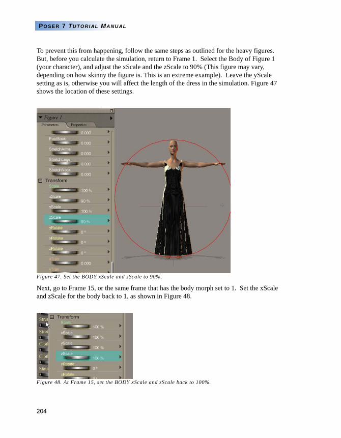
204
POSER 7 TUTORIAL MANUAL
To prevent this from happening, follow the same steps as outlined for the heavy figures. But, before you calculate the simulation, return to Frame 1. Select the Body of Figure 1 (your character), and adjust the xScale and the zScale to 90% (This figure may vary, depending on how skinny the figure is. This is an extreme example). Leave the yScale setting as is, otherwise you will affect the length of the dress in the simulation. Figure 47 shows the location of these settings.
Figure 47. Set the BODY xScale and zScale to 90%.
Next, go to Frame 15, or the same frame that has the body morph set to 1. Set the xScale and zScale for the body back to 1, as shown in Figure 48.
Figure 48. At Frame 15, set the BODY xScale and zScale back to 100%.
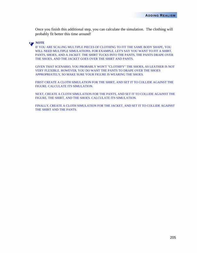
205
ADDING REALISM
Once you finish this additional step, you can calculate the simulation. The clothing will probably fit better this time around!
NOTEIF YOU ARE SCALING MULTIPLE PIECES OF CLOTHING TO FIT THE SAME BODY SHAPE, YOU WILL NEED MULTIPLE SIMULATIONS. FOR EXAMPLE, LET'S SAY YOU WANT TO FIT A SHIRT, PANTS, SHOES, AND A JACKET. THE SHIRT TUCKS INTO THE PANTS, THE PANTS DRAPE OVER THE SHOES, AND THE JACKET GOES OVER THE SHIRT AND PANTS.
GIVEN THAT SCENARIO, YOU PROBABLY WON'T "CLOTHIFY" THE SHOES, AS LEATHER IS NOT VERY FLEXIBLE. HOWEVER, YOU DO WANT THE PANTS TO DRAPE OVER THE SHOES APPROPRIATELY, SO MAKE SURE YOUR FIGURE IS WEARING THE SHOES.
FIRST CREATE A CLOTH SIMULATION FOR THE SHIRT, AND SET IT TO COLLIDE AGAINST THE FIGURE. CALCULATE ITS SIMULATION.
NEXT, CREATE A CLOTH SIMULATION FOR THE PANTS, AND SET IT TO COLLIDE AGAINST THE FIGURE, THE SHIRT, AND THE SHOES. CALCULATE ITS SIMULATION.
FINALLY, CREATE A CLOTH SIMULATION FOR THE JACKET, AND SET IT TO COLLIDE AGAINST THE SHIRT AND THE PANTS.
206
POSER 7 TUTORIAL MANUAL
Chapter 12: The Hair Roomby Denise Tyler
ou have no doubt seen furry creatures in animated movies such as Shrek or Monsters, Inc., and observed their hair blowing in the wind, or reacting to gravity or other movement when the characters change position. The hair on those
characters uses a technique that is similar to what you find in Poser 7's Hair room.
To begin, notice that Poser 7 uses three different types of hair, each of which have strengths and weaknesses. The first type of hair uses an HR2 or HRZ extension. This type of hair uses a geometry file, a texture map, and a transparency map, and can look quite realistic. HR2 files are usually configured as a smart prop that automatically attaches itself to a figure's head. You can also attach them yourself with the Figure > Set Figure Parent or Object > Change Parent commands.
Though HR2 hair does move along with the character as far as positioning goes, it requires morphs to make it pose correctly when the head bends in any direction. For example, if you add long hair to a character and then bend her head forward, the bottom of the hair sticks out. In many cases, morphs are added to make the hair bend appropriately, as shown in Figure 1.
Y
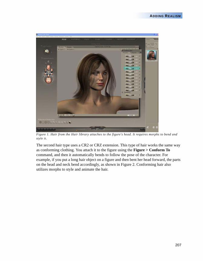
207
ADDING REALISM
Figure 1. Hair from the Hair library attaches to the figure's head. It requires morphs to bend and style it.
The second hair type uses a CR2 or CRZ extension. This type of hair works the same way as conforming clothing. You attach it to the figure using the Figure > Conform To command, and then it automatically bends to follow the pose of the character. For example, if you put a long hair object on a figure and then bent her head forward, the parts on the head and neck bend accordingly, as shown in Figure 2. Conforming hair also utilizes morphs to style and animate the hair.
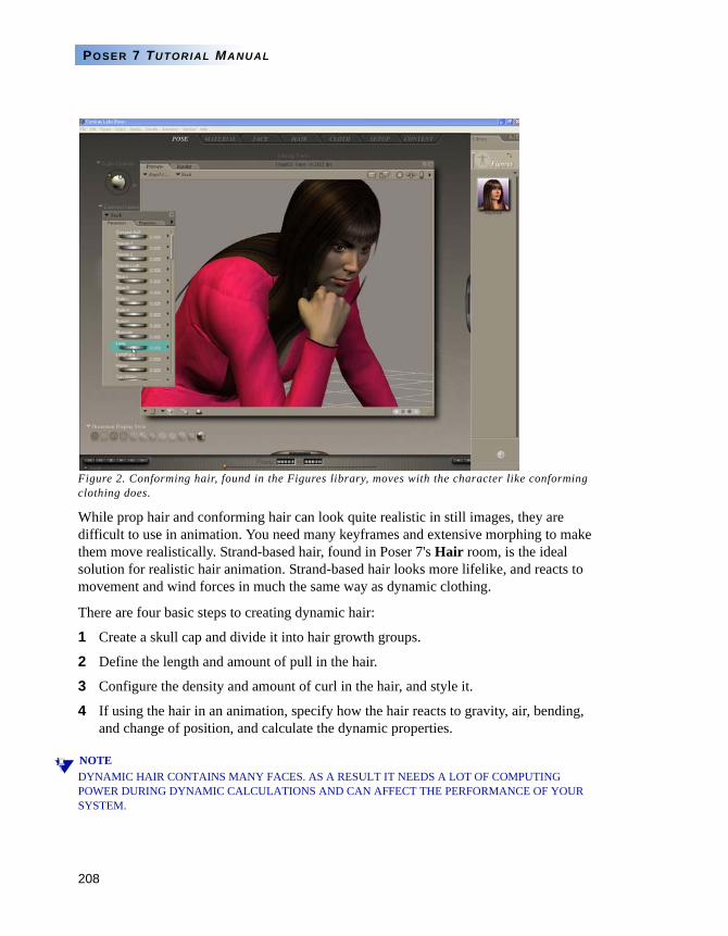
208
POSER 7 TUTORIAL MANUAL
Figure 2. Conforming hair, found in the Figures library, moves with the character like conforming clothing does.
While prop hair and conforming hair can look quite realistic in still images, they are difficult to use in animation. You need many keyframes and extensive morphing to make them move realistically. Strand-based hair, found in Poser 7's Hair room, is the ideal solution for realistic hair animation. Strand-based hair looks more lifelike, and reacts to movement and wind forces in much the same way as dynamic clothing.
There are four basic steps to creating dynamic hair:
1 Create a skull cap and divide it into hair growth groups.
2 Define the length and amount of pull in the hair.
3 Configure the density and amount of curl in the hair, and style it.
4 If using the hair in an animation, specify how the hair reacts to gravity, air, bending, and change of position, and calculate the dynamic properties.
NOTEDYNAMIC HAIR CONTAINS MANY FACES. AS A RESULT IT NEEDS A LOT OF COMPUTING POWER DURING DYNAMIC CALCULATIONS AND CAN AFFECT THE PERFORMANCE OF YOUR SYSTEM.
209
ADDING REALISM
A good way to approach hair is to first add all of the hair groups to the skullcap, using the Group Editor. Then, start with the bottom-most layer, growing and styling the hair on it. As you work your way up to the crown, you continue to add hair.
TASK 1: QUICK START TO CREATING AND STYLING HAIR
Let’s take the basic steps of hair creation one step farther. In this quick start tutorial, you’ll create hair from a skull cap that only has one group. You’ll create a nice, soft hairstyle with a little bit of curl and styling.
NOTETHOUGH YOU CAN ADD HAIR DIRECTLY TO A CHARACTER'S HEAD, YOU WON'T BE ABLE TO DISTRIBUTE IT WITHOUT THE CHARACTER, OR USE THE HAIR WITH OTHER CHARACTERS. THE ONLY WAY YOU CAN SAVE A CHARACTER, WITH HAIR, IS TO SAVE THE ENTIRE PROJECT. THIS MAKES IT DIFFICULT TO USE THE SAME HAIRSTYLE ON ANY CHARACTER.
ADDING GROUPS
To style your first hair style, follow these steps:
1 Open the project named JessiHairRoom01.pzz from the Tutorials/HairRoom folder in your Poser 7 installation. This file has Jessi in the default pose, wearing a red and black cocktail dress. She is also wearing a skull cap that has no hair groups defined. The skull cap appears as a transparent object on the head.
2 Enter the Hair room. If necessary, choose the Face Camera so that you can see Jessi as shown in Figure 3.
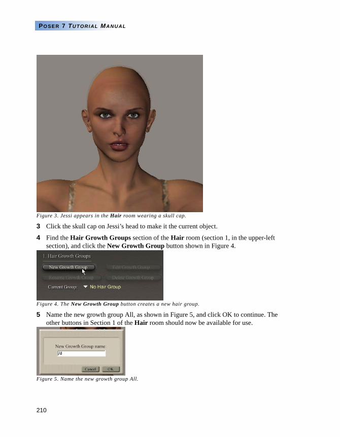
210
POSER 7 TUTORIAL MANUAL
Figure 3. Jessi appears in the Hair room wearing a skull cap.
3 Click the skull cap on Jessi’s head to make it the current object.
4 Find the Hair Growth Groups section of the Hair room (section 1, in the upper-left section), and click the New Growth Group button shown in Figure 4.
Figure 4. The New Growth Group button creates a new hair group.
5 Name the new growth group All, as shown in Figure 5, and click OK to continue. The other buttons in Section 1 of the Hair room should now be available for use.
Figure 5. Name the new growth group All.
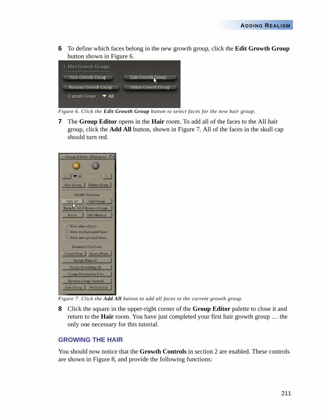
211
ADDING REALISM
6 To define which faces belong in the new growth group, click the Edit Growth Group button shown in Figure 6.
Figure 6. Click the Edit Growth Group button to select faces for the new hair group.
7 The Group Editor opens in the Hair room. To add all of the faces to the All hair group, click the Add All button, shown in Figure 7. All of the faces in the skull cap should turn red.
Figure 7. Click the Add All button to add all faces to the current growth group.
8 Click the square in the upper-right corner of the Group Editor palette to close it and return to the Hair room. You have just completed your first hair growth group … the only one necessary for this tutorial.
GROWING THE HAIR
You should now notice that the Growth Controls in section 2 are enabled. These controls are shown in Figure 8, and provide the following functions:
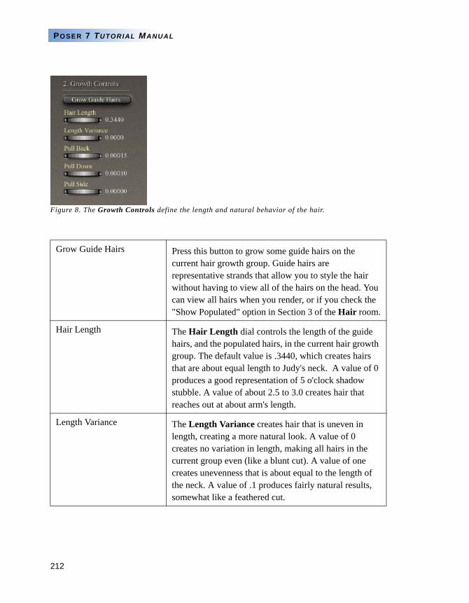
212
POSER 7 TUTORIAL MANUAL
Figure 8. The Growth Controls define the length and natural behavior of the hair.
Grow Guide Hairs Press this button to grow some guide hairs on the current hair growth group. Guide hairs are representative strands that allow you to style the hair without having to view all of the hairs on the head. You can view all hairs when you render, or if you check the "Show Populated" option in Section 3 of the Hair room.
Hair Length The Hair Length dial controls the length of the guide hairs, and the populated hairs, in the current hair growth group. The default value is .3440, which creates hairs that are about equal length to Judy's neck. A value of 0 produces a good representation of 5 o'clock shadow stubble. A value of about 2.5 to 3.0 creates hair that reaches out at about arm's length.
Length Variance The Length Variance creates hair that is uneven in length, creating a more natural look. A value of 0 creates no variation in length, making all hairs in the current group even (like a blunt cut). A value of one creates unevenness that is about equal to the length of the neck. A value of .1 produces fairly natural results, somewhat like a feathered cut.
213
ADDING REALISM
1 Click the Grow Guide Hairs button. Initially you’ll see the wild style shown in Figure 9. There are two things to point out here: first, the hair that you see in the render will not be as thin as what you see in the window here. These are only representative guide hairs that help you style the hair without having to wade through thousands of hairs at once. Secondly, all of the hairs you see on the head are roughly the same length all across the head. For this style it’s okay, but later you’ll learn how you can control hair lengths a little better.
Pull Back Not to be confused with pulling back from styling, the Pull Back setting controls how the hair in the hair group is naturally pulled back. For example, men's short hair pulls back naturally from the hair line. A value of 0 does not pull hair back at all. Increase values above 0 to pull hair backward, and decrease values below 0 to push hair forward.
Pull Down The Pull Down setting controls how much the hair naturally pulls down because of gravity or length. Long hair weighs more than short hair, so its natural tendency to pull downward is greater. Increase the setting to pull the hair downward, and decrease the setting below 0 to create hair that sticks up. A value of .005 creates a nice natural bend for medium to long hair.
Pull Side The Pull Side setting controls how much the hair naturally pulls to the right or left, such as when the hair is parted. Numbers above 0 pull the hair toward the character's right, while numbers below 0 pull the hair toward the character's left side.
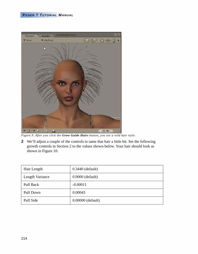
214
POSER 7 TUTORIAL MANUAL
Figure 9. After you click the Grow Guide Hairs button, you see a wild hair style.
2 We’ll adjust a couple of the controls to tame that hair a little bit. Set the following growth controls in Section 2 to the values shown below. Your hair should look as shown in Figure 10.
Hair Length 0.3440 (default)
Length Variance 0.0000 (default)
Pull Back -0.00011
Pull Down 0.00043
Pull Side 0.00000 (default)
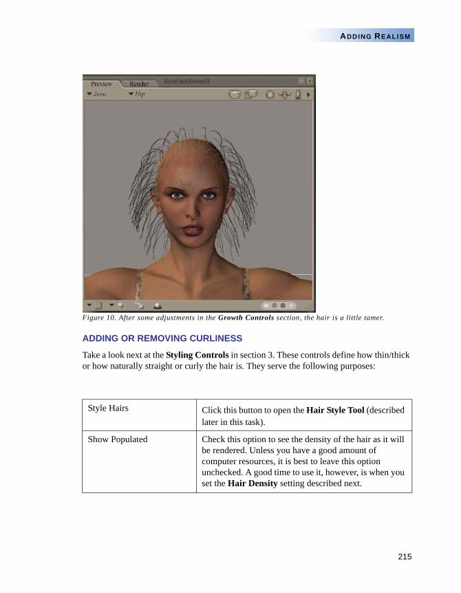
215
ADDING REALISM
Figure 10. After some adjustments in the Growth Controls section, the hair is a little tamer.
ADDING OR REMOVING CURLINESS
Take a look next at the Styling Controls in section 3. These controls define how thin/thick or how naturally straight or curly the hair is. They serve the following purposes:
Style Hairs Click this button to open the Hair Style Tool (described later in this task).
Show Populated Check this option to see the density of the hair as it will be rendered. Unless you have a good amount of computer resources, it is best to leave this option unchecked. A good time to use it, however, is when you set the Hair Density setting described next.
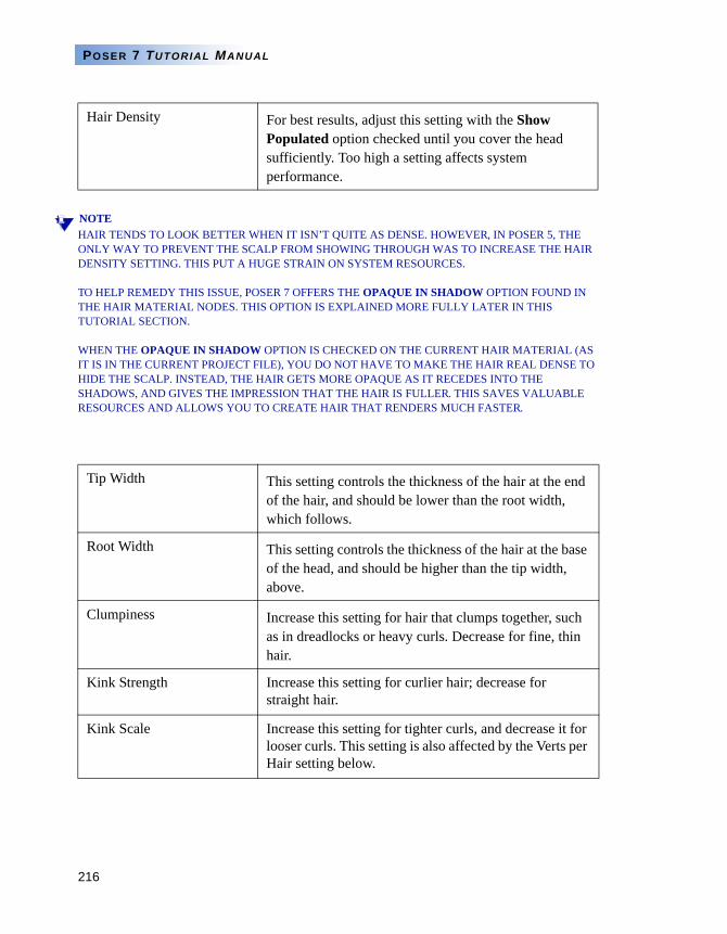
216
POSER 7 TUTORIAL MANUAL
NOTEHAIR TENDS TO LOOK BETTER WHEN IT ISN’T QUITE AS DENSE. HOWEVER, IN POSER 5, THE ONLY WAY TO PREVENT THE SCALP FROM SHOWING THROUGH WAS TO INCREASE THE HAIR DENSITY SETTING. THIS PUT A HUGE STRAIN ON SYSTEM RESOURCES.
TO HELP REMEDY THIS ISSUE, POSER 7 OFFERS THE OPAQUE IN SHADOW OPTION FOUND IN THE HAIR MATERIAL NODES. THIS OPTION IS EXPLAINED MORE FULLY LATER IN THIS TUTORIAL SECTION.
WHEN THE OPAQUE IN SHADOW OPTION IS CHECKED ON THE CURRENT HAIR MATERIAL (AS IT IS IN THE CURRENT PROJECT FILE), YOU DO NOT HAVE TO MAKE THE HAIR REAL DENSE TO HIDE THE SCALP. INSTEAD, THE HAIR GETS MORE OPAQUE AS IT RECEDES INTO THE SHADOWS, AND GIVES THE IMPRESSION THAT THE HAIR IS FULLER. THIS SAVES VALUABLE RESOURCES AND ALLOWS YOU TO CREATE HAIR THAT RENDERS MUCH FASTER.
Hair Density For best results, adjust this setting with the Show Populated option checked until you cover the head sufficiently. Too high a setting affects system performance.
Tip Width This setting controls the thickness of the hair at the end of the hair, and should be lower than the root width, which follows.
Root Width This setting controls the thickness of the hair at the base of the head, and should be higher than the tip width, above.
Clumpiness Increase this setting for hair that clumps together, such as in dreadlocks or heavy curls. Decrease for fine, thin hair.
Kink Strength Increase this setting for curlier hair; decrease for straight hair.
Kink Scale Increase this setting for tighter curls, and decrease it for looser curls. This setting is also affected by the Verts per Hair setting below.
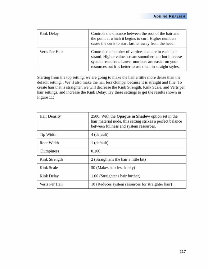
217
ADDING REALISM
Starting from the top setting, we are going to make the hair a little more dense than the default setting. . We’ll also make the hair less clumpy, because it is straight and fine. To create hair that is straighter, we will decrease the Kink Strength, Kink Scale, and Verts per hair settings, and increase the Kink Delay. Try these settings to get the results shown in Figure 11:
Kink Delay Controls the distance between the root of the hair and the point at which it begins to curl. Higher numbers cause the curls to start farther away from the head.
Verts Per Hair Controls the number of vertices that are in each hair strand. Higher values create smoother hair but increase system resources. Lower numbers are easier on your resources but it is better to use them in straight styles.
Hair Density 2500. With the Opaque in Shadow option set in the hair material node, this setting strikes a perfect balance between fullness and system resources.
Tip Width 4 (default)
Root Width 1 (default)
Clumpiness 0.100
Kink Strength 2 (Straightens the hair a little bit)
Kink Scale 50 (Makes hair less kinky)
Kink Delay 1.00 (Straightens hair further)
Verts Per Hair 10 (Reduces system resources for straighter hair)
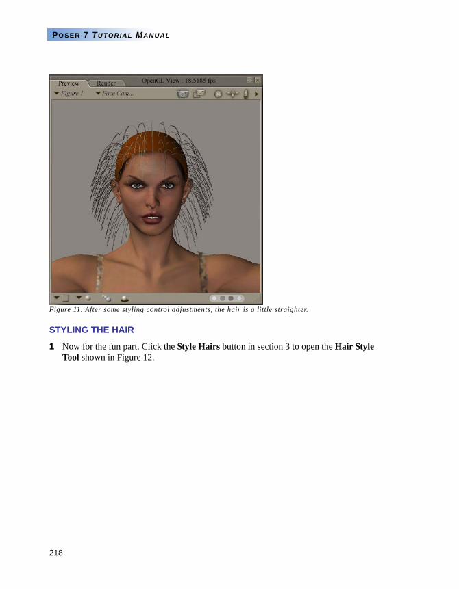
218
POSER 7 TUTORIAL MANUAL
Figure 11. After some styling control adjustments, the hair is a little straighter.
STYLING THE HAIR
1 Now for the fun part. Click the Style Hairs button in section 3 to open the Hair Style Tool shown in Figure 12.
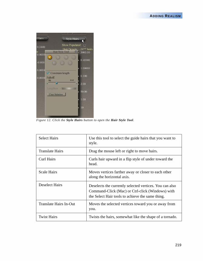
219
ADDING REALISM
Figure 12. Click the Style Hairs button to open the Hair Style Tool.
Select Hairs Use this tool to select the guide hairs that you want to style.
Translate Hairs Drag the mouse left or right to move hairs.
Curl Hairs Curls hair upward in a flip style of under toward the head.
Scale Hairs Moves vertices farther away or closer to each other along the horizontal axis.
Deselect Hairs Deselects the currently selected vertices. You can also Command-Click (Mac) or Ctrl-click (Windows) with the Select Hair tools to achieve the same thing.
Translate Hairs In-Out Moves the selected vertices toward you or away from you.
Twist Hairs Twists the hairs, somewhat like the shape of a tornado.
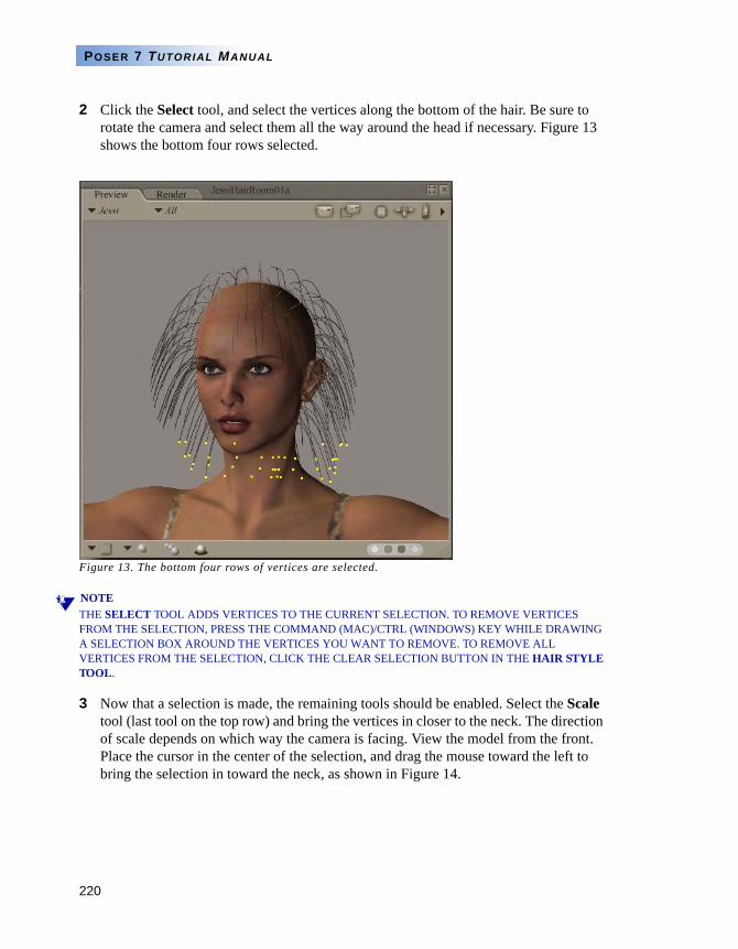
220
POSER 7 TUTORIAL MANUAL
2 Click the Select tool, and select the vertices along the bottom of the hair. Be sure to rotate the camera and select them all the way around the head if necessary. Figure 13 shows the bottom four rows selected.
Figure 13. The bottom four rows of vertices are selected.
NOTETHE SELECT TOOL ADDS VERTICES TO THE CURRENT SELECTION. TO REMOVE VERTICES FROM THE SELECTION, PRESS THE COMMAND (MAC)/CTRL (WINDOWS) KEY WHILE DRAWING A SELECTION BOX AROUND THE VERTICES YOU WANT TO REMOVE. TO REMOVE ALL VERTICES FROM THE SELECTION, CLICK THE CLEAR SELECTION BUTTON IN THE HAIR STYLE TOOL.
3 Now that a selection is made, the remaining tools should be enabled. Select the Scale tool (last tool on the top row) and bring the vertices in closer to the neck. The direction of scale depends on which way the camera is facing. View the model from the front. Place the cursor in the center of the selection, and drag the mouse toward the left to bring the selection in toward the neck, as shown in Figure 14.
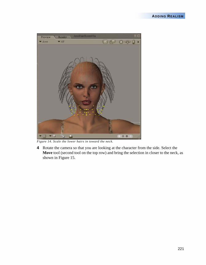
221
ADDING REALISM
Figure 14. Scale the lower hairs in toward the neck.
4 Rotate the camera so that you are looking at the character from the side. Select the Move tool (second tool on the top row) and bring the selection in closer to the neck, as shown in Figure 15.
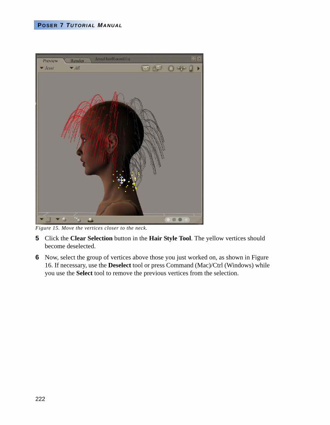
222
POSER 7 TUTORIAL MANUAL
Figure 15. Move the vertices closer to the neck.
5 Click the Clear Selection button in the Hair Style Tool. The yellow vertices should become deselected.
6 Now, select the group of vertices above those you just worked on, as shown in Figure 16. If necessary, use the Deselect tool or press Command (Mac)/Ctrl (Windows) while you use the Select tool to remove the previous vertices from the selection.

223
ADDING REALISM
Figure 16. Select another set of vertices above the previous selection.
7 Adjust the Lengthen slider in the Hair Style Tool until your guide hairs are approximately the same length as the previous layer, as shown in Figure 17.
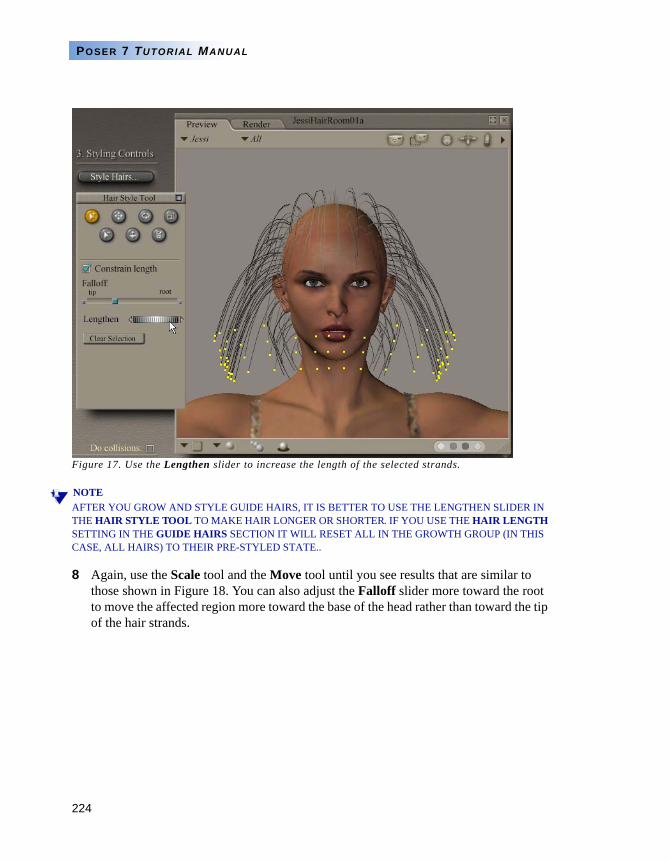
224
POSER 7 TUTORIAL MANUAL
Figure 17. Use the Lengthen slider to increase the length of the selected strands.
NOTEAFTER YOU GROW AND STYLE GUIDE HAIRS, IT IS BETTER TO USE THE LENGTHEN SLIDER IN THE HAIR STYLE TOOL TO MAKE HAIR LONGER OR SHORTER. IF YOU USE THE HAIR LENGTH SETTING IN THE GUIDE HAIRS SECTION IT WILL RESET ALL IN THE GROWTH GROUP (IN THIS CASE, ALL HAIRS) TO THEIR PRE-STYLED STATE..
8 Again, use the Scale tool and the Move tool until you see results that are similar to those shown in Figure 18. You can also adjust the Falloff slider more toward the root to move the affected region more toward the base of the head rather than toward the tip of the hair strands.
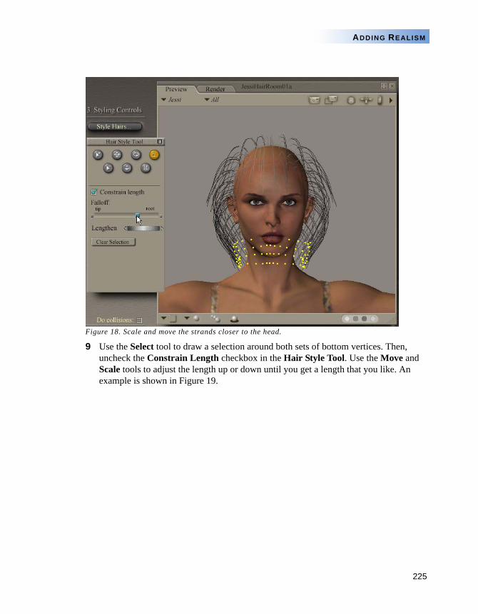
225
ADDING REALISM
Figure 18. Scale and move the strands closer to the head.
9 Use the Select tool to draw a selection around both sets of bottom vertices. Then, uncheck the Constrain Length checkbox in the Hair Style Tool. Use the Move and Scale tools to adjust the length up or down until you get a length that you like. An example is shown in Figure 19.
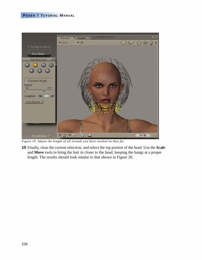
226
POSER 7 TUTORIAL MANUAL
Figure 19. Adjust the length of all strands you have worked on thus far.
10 Finally, clear the current selection, and select the top portion of the head. Use the Scale and Move tools to bring the hair in closer to the head, keeping the bangs at a proper length. The results should look similar to that shown in Figure 20.
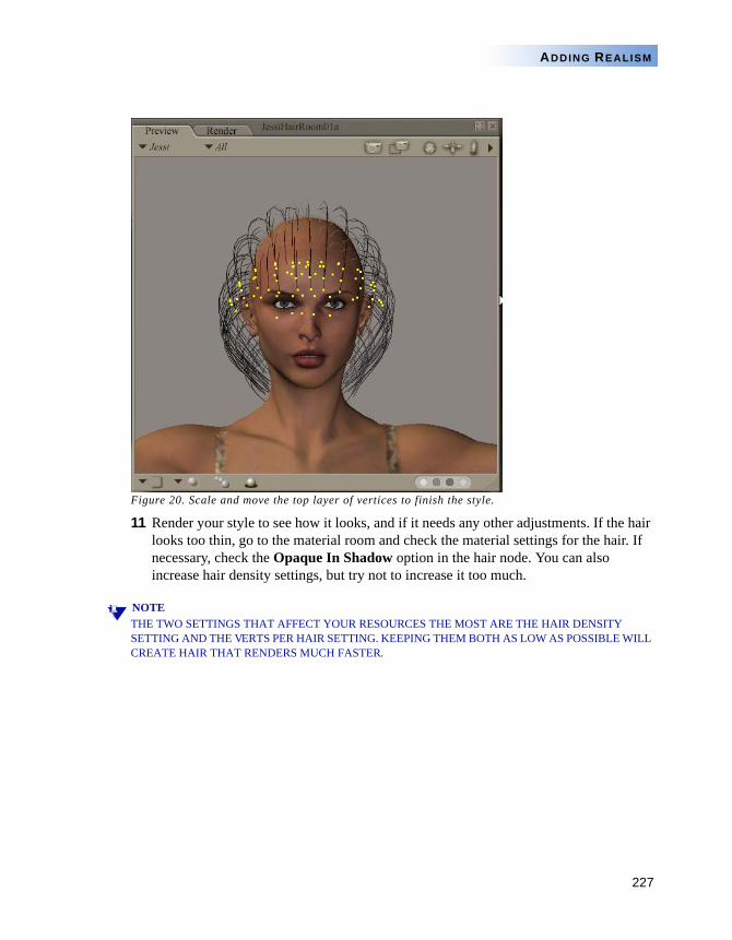
227
ADDING REALISM
Figure 20. Scale and move the top layer of vertices to finish the style.
11 Render your style to see how it looks, and if it needs any other adjustments. If the hair looks too thin, go to the material room and check the material settings for the hair. If necessary, check the Opaque In Shadow option in the hair node. You can also increase hair density settings, but try not to increase it too much.
NOTETHE TWO SETTINGS THAT AFFECT YOUR RESOURCES THE MOST ARE THE HAIR DENSITY SETTING AND THE VERTS PER HAIR SETTING. KEEPING THEM BOTH AS LOW AS POSSIBLE WILL CREATE HAIR THAT RENDERS MUCH FASTER.
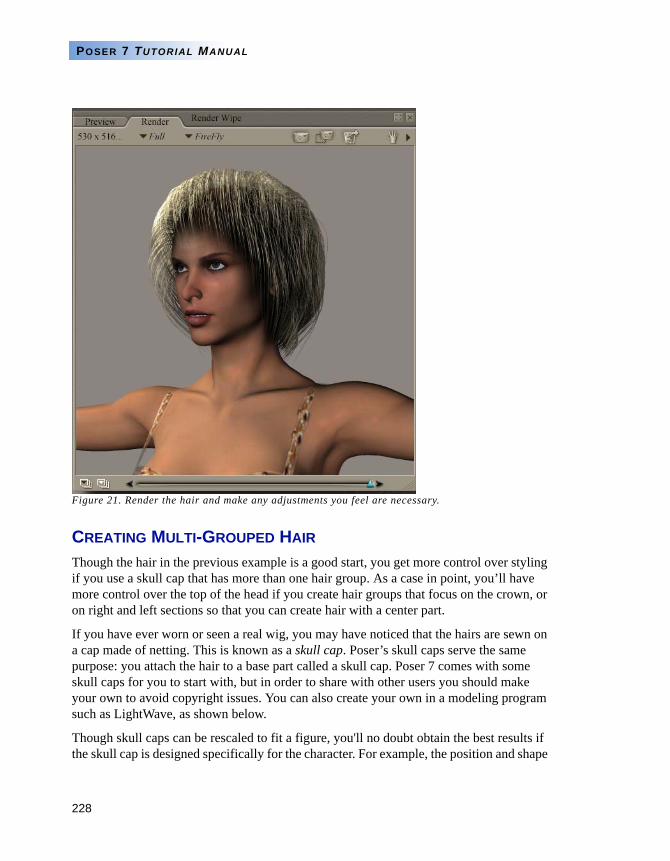
228
POSER 7 TUTORIAL MANUAL
Figure 21. Render the hair and make any adjustments you feel are necessary.
CREATING MULTI-GROUPED HAIR
Though the hair in the previous example is a good start, you get more control over styling if you use a skull cap that has more than one hair group. As a case in point, you’ll have more control over the top of the head if you create hair groups that focus on the crown, or on right and left sections so that you can create hair with a center part.
If you have ever worn or seen a real wig, you may have noticed that the hairs are sewn on a cap made of netting. This is known as a skull cap. Poser’s skull caps serve the same purpose: you attach the hair to a base part called a skull cap. Poser 7 comes with some skull caps for you to start with, but in order to share with other users you should make your own to avoid copyright issues. You can also create your own in a modeling program such as LightWave, as shown below.
Though skull caps can be rescaled to fit a figure, you'll no doubt obtain the best results if the skull cap is designed specifically for the character. For example, the position and shape
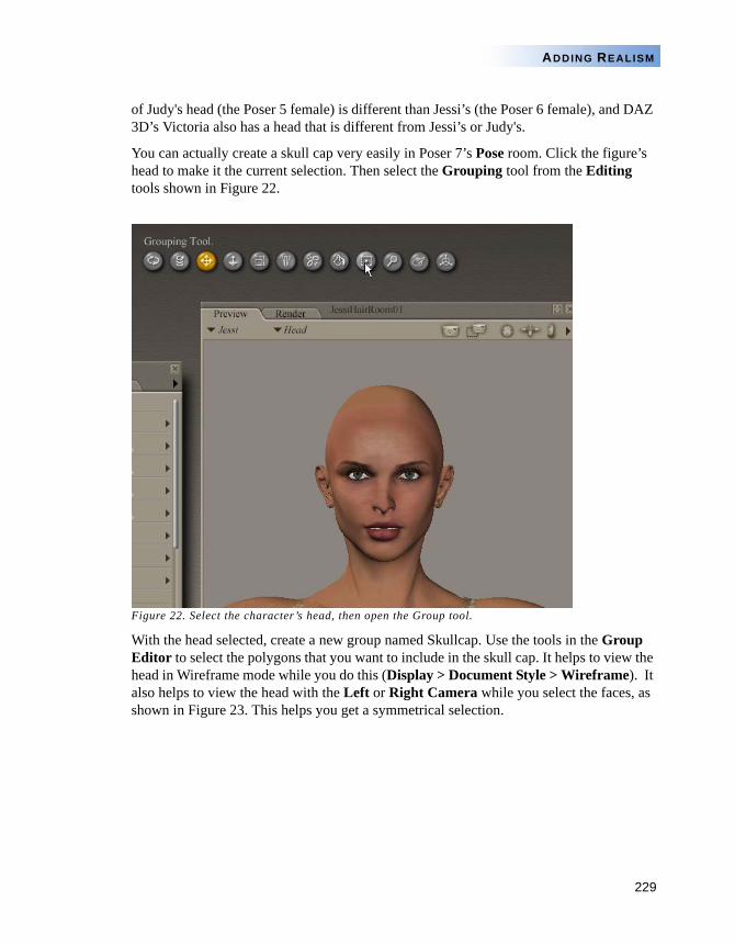
229
ADDING REALISM
of Judy's head (the Poser 5 female) is different than Jessi’s (the Poser 6 female), and DAZ 3D’s Victoria also has a head that is different from Jessi’s or Judy's.
You can actually create a skull cap very easily in Poser 7’s Pose room. Click the figure’s head to make it the current selection. Then select the Grouping tool from the Editing tools shown in Figure 22.
Figure 22. Select the character’s head, then open the Group tool.
With the head selected, create a new group named Skullcap. Use the tools in the Group Editor to select the polygons that you want to include in the skull cap. It helps to view the head in Wireframe mode while you do this (Display > Document Style > Wireframe). It also helps to view the head with the Left or Right Camera while you select the faces, as shown in Figure 23. This helps you get a symmetrical selection.
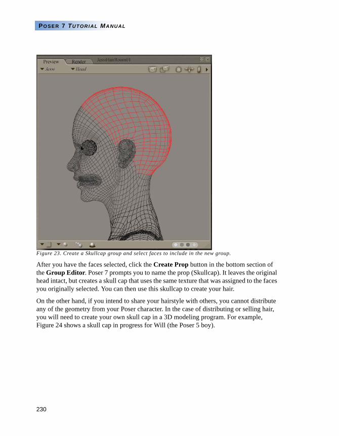
230
POSER 7 TUTORIAL MANUAL
Figure 23. Create a Skullcap group and select faces to include in the new group.
After you have the faces selected, click the Create Prop button in the bottom section of the Group Editor. Poser 7 prompts you to name the prop (Skullcap). It leaves the original head intact, but creates a skull cap that uses the same texture that was assigned to the faces you originally selected. You can then use this skullcap to create your hair.
On the other hand, if you intend to share your hairstyle with others, you cannot distribute any of the geometry from your Poser character. In the case of distributing or selling hair, you will need to create your own skull cap in a 3D modeling program. For example, Figure 24 shows a skull cap in progress for Will (the Poser 5 boy).
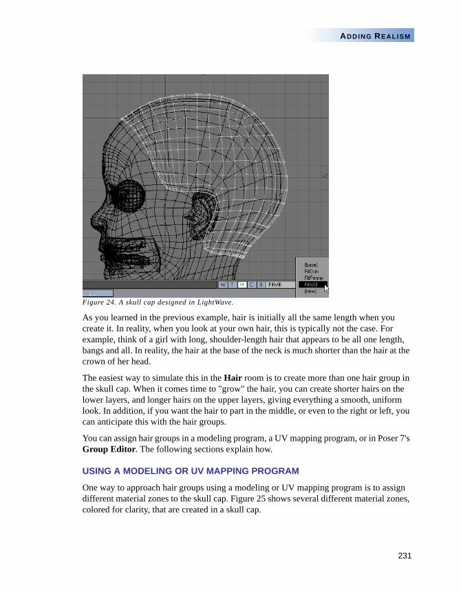
231
ADDING REALISM
Figure 24. A skull cap designed in LightWave.
As you learned in the previous example, hair is initially all the same length when you create it. In reality, when you look at your own hair, this is typically not the case. For example, think of a girl with long, shoulder-length hair that appears to be all one length, bangs and all. In reality, the hair at the base of the neck is much shorter than the hair at the crown of her head.
The easiest way to simulate this in the Hair room is to create more than one hair group in the skull cap. When it comes time to "grow" the hair, you can create shorter hairs on the lower layers, and longer hairs on the upper layers, giving everything a smooth, uniform look. In addition, if you want the hair to part in the middle, or even to the right or left, you can anticipate this with the hair groups.
You can assign hair groups in a modeling program, a UV mapping program, or in Poser 7's Group Editor. The following sections explain how.
USING A MODELING OR UV MAPPING PROGRAM
One way to approach hair groups using a modeling or UV mapping program is to assign different material zones to the skull cap. Figure 25 shows several different material zones, colored for clarity, that are created in a skull cap.
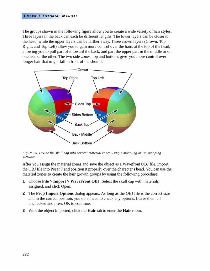
232
POSER 7 TUTORIAL MANUAL
The groups shown in the following figure allow you to create a wide variety of hair styles. Three layers in the back can each be different lengths. The lower layers can be closer to the head, while the upper layers can be farther away. Three crown layers (Crown, Top Right, and Top Left) allow you to gain more control over the hairs at the top of the head, allowing you to pull part of it toward the back, and part the upper part in the middle or on one side or the other. The two side zones, top and bottom, give you more control over longer hair that might fall in front of the shoulder.
Figure 25. Divide the skull cap into several material zones using a modeling or UV mapping software.
After you assign the material zones and save the object as a Wavefront OBJ file, import the OBJ file into Poser 7 and position it properly over the character's head. You can use the material zones to create the hair growth groups by using the following procedure:
1 Choose File > Import > WaveFront OBJ. Select the skull cap with materials assigned, and click Open.
2 The Prop Import Options dialog appears. As long as the OBJ file is the correct size and in the correct position, you don't need to check any options. Leave them all unchecked and press OK to continue.
3 With the object imported, click the Hair tab to enter the Hair room.
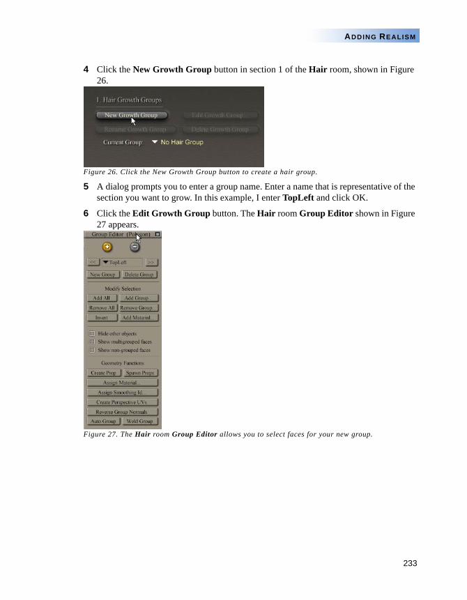
233
ADDING REALISM
4 Click the New Growth Group button in section 1 of the Hair room, shown in Figure 26.
Figure 26. Click the New Growth Group button to create a hair group.
5 A dialog prompts you to enter a group name. Enter a name that is representative of the section you want to grow. In this example, I enter TopLeft and click OK.
6 Click the Edit Growth Group button. The Hair room Group Editor shown in Figure 27 appears.
Figure 27. The Hair room Group Editor allows you to select faces for your new group.
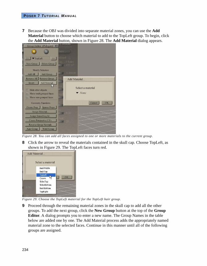
234
POSER 7 TUTORIAL MANUAL
7 Because the OBJ was divided into separate material zones, you can use the Add Material button to choose which material to add to the TopLeft group. To begin, click the Add Material button, shown in Figure 28. The Add Material dialog appears.
Figure 28. You can add all faces assigned to one or more materials to the current group.
8 Click the arrow to reveal the materials contained in the skull cap. Choose TopLeft, as shown in Figure 29. The TopLeft faces turn red.
Figure 29. Choose the TopLeft material for the TopLeft hair group.
9 Proceed through the remaining material zones in the skull cap to add all the other groups. To add the next group, click the New Group button at the top of the Group Editor. A dialog prompts you to enter a new name. The Group Names in the table below are added one by one. The Add Material process adds the appropriately named material zone to the selected faces. Continue in this manner until all of the following groups are assigned.
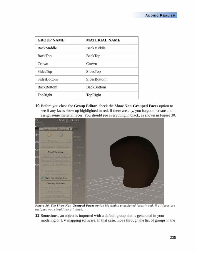
235
ADDING REALISM
10 Before you close the Group Editor, check the Show Non-Grouped Faces option to see if any faces show up highlighted in red. If there are any, you forgot to create and assign some material faces. You should see everything in black, as shown in Figure 30.
Figure 30. The Show Non-Grouped Faces option highlights unassigned faces in red. If all faces are assigned you should see all black.
11 Sometimes, an object is imported with a default group that is generated in your modeling or UV mapping software. In that case, move through the list of groups in the
GROUP NAME MATERIAL NAME
BackMiddle BackMiddle
BackTop BackTop
Crown Crown
SidesTop SidesTop
SidesBottom SidesBottom
BackBottom BackBottom
TopRight TopRight
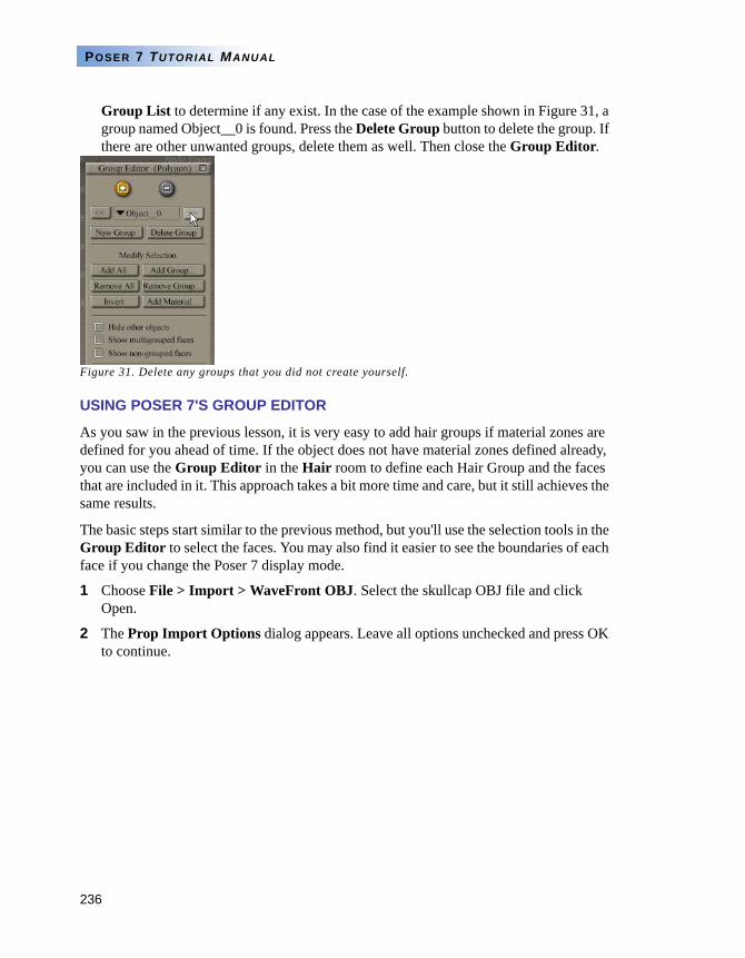
236
POSER 7 TUTORIAL MANUAL
Group List to determine if any exist. In the case of the example shown in Figure 31, a group named Object__0 is found. Press the Delete Group button to delete the group. If there are other unwanted groups, delete them as well. Then close the Group Editor.
Figure 31. Delete any groups that you did not create yourself.
USING POSER 7'S GROUP EDITOR
As you saw in the previous lesson, it is very easy to add hair groups if material zones are defined for you ahead of time. If the object does not have material zones defined already, you can use the Group Editor in the Hair room to define each Hair Group and the faces that are included in it. This approach takes a bit more time and care, but it still achieves the same results.
The basic steps start similar to the previous method, but you'll use the selection tools in the Group Editor to select the faces. You may also find it easier to see the boundaries of each face if you change the Poser 7 display mode.
1 Choose File > Import > WaveFront OBJ. Select the skullcap OBJ file and click Open.
2 The Prop Import Options dialog appears. Leave all options unchecked and press OK to continue.
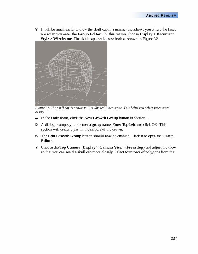
237
ADDING REALISM
3 It will be much easier to view the skull cap in a manner that shows you where the faces are when you enter the Group Editor. For this reason, choose Display > Document Style > Wireframe. The skull cap should now look as shown in Figure 32.
Figure 32. The skull cap is shown in Flat Shaded Lined mode. This helps you select faces more easily.
4 In the Hair room, click the New Growth Group button in section 1.
5 A dialog prompts you to enter a group name. Enter TopLeft and click OK. This section will create a part in the middle of the crown.
6 The Edit Growth Group button should now be enabled. Click it to open the Group Editor.
7 Choose the Top Camera (Display > Camera View > From Top) and adjust the view so that you can see the skull cap more closely. Select four rows of polygons from the
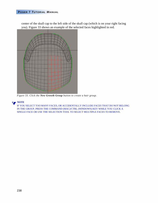
238
POSER 7 TUTORIAL MANUAL
center of the skull cap to the left side of the skull cap (which is on your right facing you). Figure 33 shows an example of the selected faces highlighted in red.
Figure 33. Click the New Growth Group button to create a hair group.
NOTEIF YOU SELECT TOO MANY FACES, OR ACCIDENTALLY INCLUDE FACES THAT DO NOT BELONG IN THE GROUP, PRESS THE COMMAND (MAC)/CTRL (WINDOWS) KEY WHILE YOU CLICK A SINGLE FACE OR USE THE SELECTION TOOL TO SELECT MULTIPLE FACES TO REMOVE.
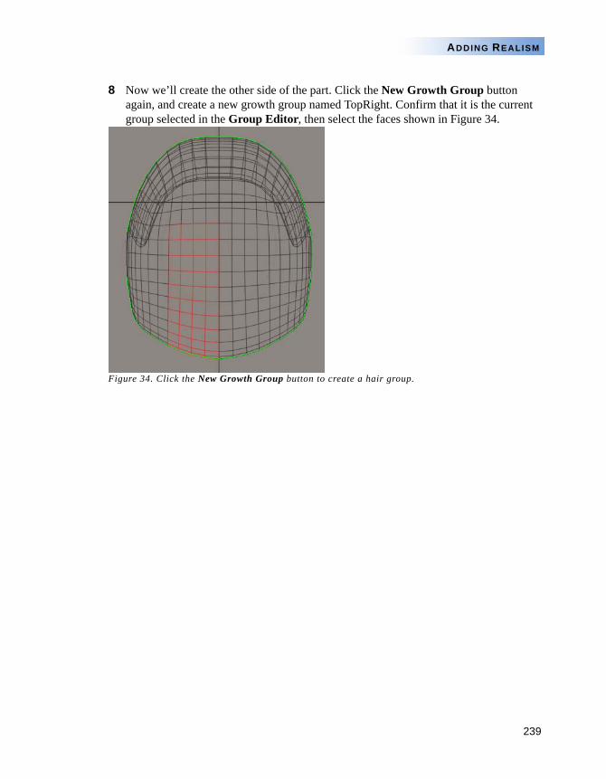
239
ADDING REALISM
8 Now we’ll create the other side of the part. Click the New Growth Group button again, and create a new growth group named TopRight. Confirm that it is the current group selected in the Group Editor, then select the faces shown in Figure 34.
Figure 34. Click the New Growth Group button to create a hair group.
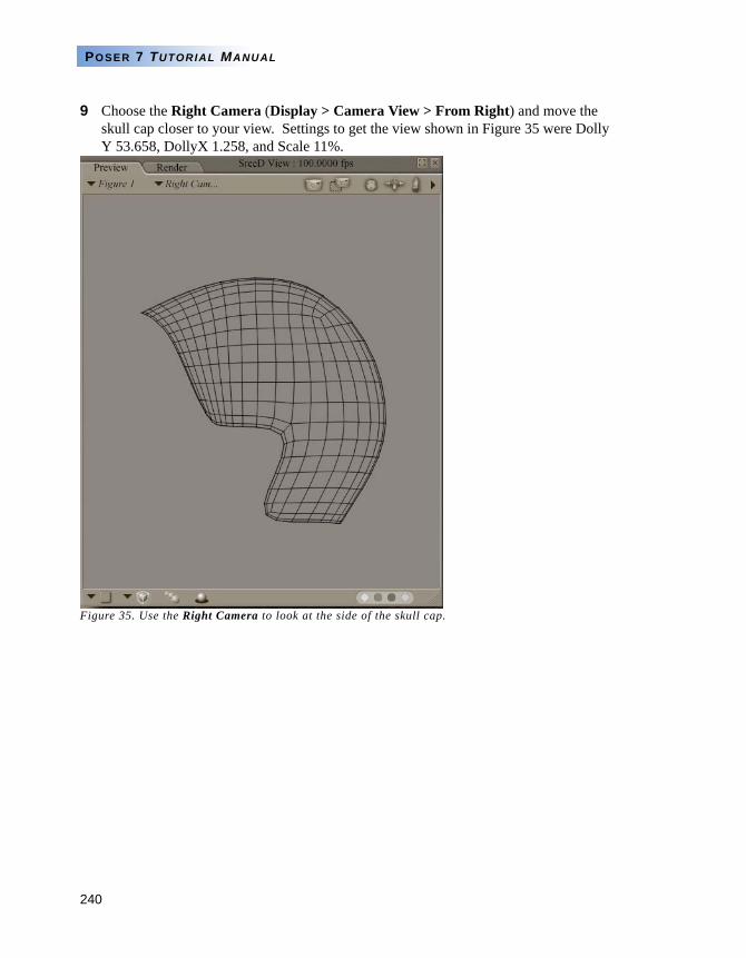
240
POSER 7 TUTORIAL MANUAL
9 Choose the Right Camera (Display > Camera View > From Right) and move the skull cap closer to your view. Settings to get the view shown in Figure 35 were Dolly Y 53.658, DollyX 1.258, and Scale 11%.
Figure 35. Use the Right Camera to look at the side of the skull cap.
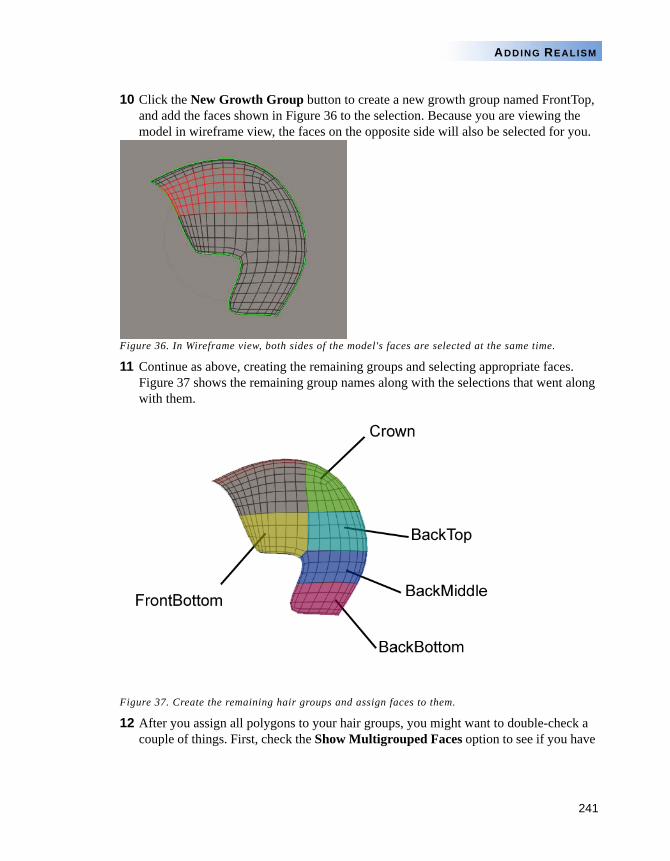
241
ADDING REALISM
10 Click the New Growth Group button to create a new growth group named FrontTop, and add the faces shown in Figure 36 to the selection. Because you are viewing the model in wireframe view, the faces on the opposite side will also be selected for you.
Figure 36. In Wireframe view, both sides of the model's faces are selected at the same time.
11 Continue as above, creating the remaining groups and selecting appropriate faces. Figure 37 shows the remaining group names along with the selections that went along with them.
Figure 37. Create the remaining hair groups and assign faces to them.
12 After you assign all polygons to your hair groups, you might want to double-check a couple of things. First, check the Show Multigrouped Faces option to see if you have
242
POSER 7 TUTORIAL MANUAL
accidentally assigned faces to more than one group. If so, they appear in red as shown in Figure 38.
Figure 38. Faces that are assigned to more than one group appear in red.
13 The reason all faces are shown in red is because modeling programs and UV mapping programs sometimes assign all faces to a group during export. In the case of the example in Figure 39, there is a group named Cap. After you uncheck the Show Multigrouped Faces option, use the arrows beneath the group name list to advance to the Cap group, and delete it with the Delete Group button.
Figure 39. Delete the Cap group from the list.
14 In a similar manner, check the Show Non-grouped Faces option. Any faces that have not yet been assigned to a group will appear in red. Uncheck the option, and select the group that should contain some or all of the missing faces, and add them to the group.
243
ADDING REALISM
15 As Figure 40 shows, you can sometimes accidentally have faces in a group that you don't want. Here, we see faces from the side of the head included in the TopLeft group. Simply press the Command (Mac)/Ctrl (Windows) key while you select the faces to remove them.
Figure 40. Remove stray faces by pressing the Command (Mac)/Ctrl (Windows) key while you select the faces to remove.
NOTEIF SOME FACES ACCIDENTALLY GET ASSIGNED TO MORE THAN ONE GROUP, DETERMINE WHICH GROUPS SHARE THE COMMON FACES. THEN, SELECT THE GROUP THAT YOU WANT TO KEEP THE FACES IN. CLICK THE REMOVE GROUP BUTTON TO CHOOSE THE GROUP THAT INCORRECTLY SHARES THE FACES.
NOTETHIS TASK SHOWS THE BASIC STEPS TO ASSIGN FACES WITH THE GROUP EDITOR. FOR MORE INFORMATION ABOUT THE GROUP EDITOR, REFER TO THE POSER 7 REFERENCE MANUAL.
TASK 2: GROWING AND STYLING MULTI-GROUPED HAIR
When you divide a skull cap into different hair groups, it gives you greater control over the way hair falls over the skull cap. Though you have more hair groups to work with, the process is very similar to the method used in Task 1.
There is one main difference when using multiple hair groups. Think about how a hairdresser cuts women's hair in the salon. If a customer has long hair, the hairdresser piles all of the hair on the top of the head, except for a section at the bottom. The bottom hair is trimmed and styled, and then the hairdresser pulls another layer down to style over the hair that has already been cut.
You will find it easiest to approach your Hair room style in the same manner. You’ll find it easier to grow and style the bottom hair group first. Then, choose the next highest hair group, and grow and style it.
244
POSER 7 TUTORIAL MANUAL
In the following tutorial, you’ll step through the process very quickly, using the skills you learned in the previous hair tutorial. For the sake of brevity, this tutorial will not incorporate the Hair Style Tool.
1 Open the file JessiHairRoom02.pzz from the Tutorials/HairRoom folder in your Poser 7 installation. This project contains Jessi with the same skull cap used in the previous exercise, except that it has been divided into the following hair growth groups:
CrownTopLeftTopRightSidesUpperBackMiddleBackLowerBack
2 Enter the Hair room and select the skull cap. Use the Current Group list to select the LowerBack growth group, as shown in Figure 41.
Figure 41. Select the LowerBack layer first.
3 In the Growth Controls section, set the values as shown below, and click the Grow Guide Hairs button. Where settings differ from the default, the reason for the change is noted in the following table.
Hair Length 0.6000 (makes hair longer)
Length Variance 0.0000
Pull Back 0.00015
Pull Down 0.00200 (weighs hair down more)
Pull Side 0.0000
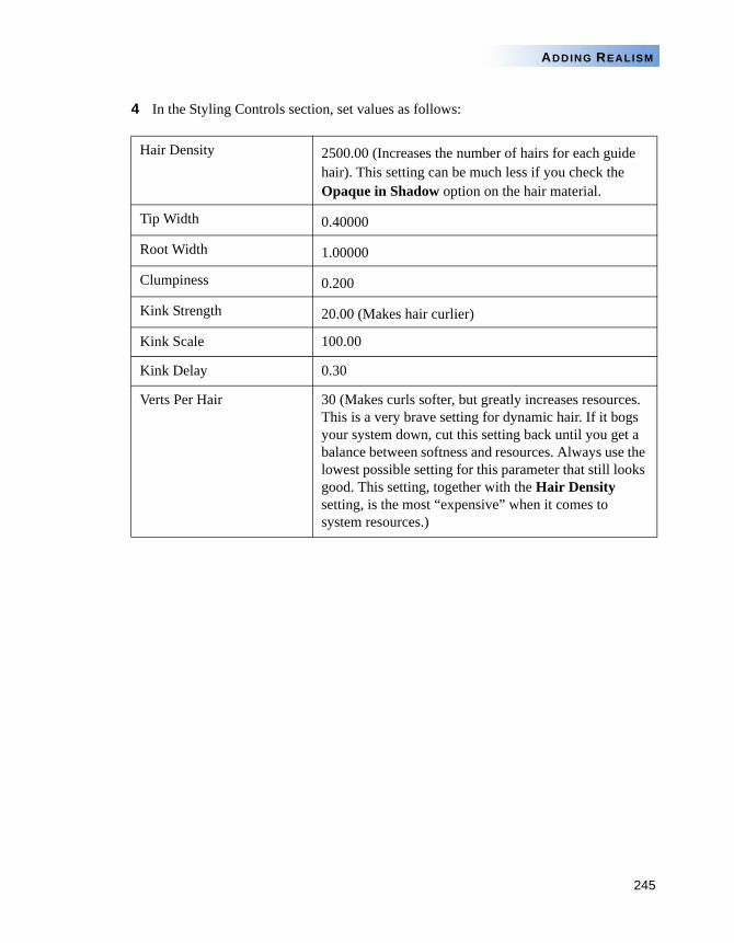
245
ADDING REALISM
4 In the Styling Controls section, set values as follows:
Hair Density 2500.00 (Increases the number of hairs for each guide hair). This setting can be much less if you check the Opaque in Shadow option on the hair material.
Tip Width 0.40000
Root Width 1.00000
Clumpiness 0.200
Kink Strength 20.00 (Makes hair curlier)
Kink Scale 100.00
Kink Delay 0.30
Verts Per Hair 30 (Makes curls softer, but greatly increases resources. This is a very brave setting for dynamic hair. If it bogs your system down, cut this setting back until you get a balance between softness and resources. Always use the lowest possible setting for this parameter that still looks good. This setting, together with the Hair Density setting, is the most “expensive” when it comes to system resources.)
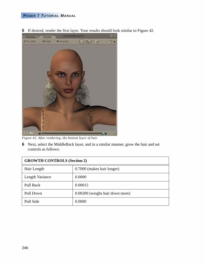
246
POSER 7 TUTORIAL MANUAL
5 If desired, render the first layer. Your results should look similar to Figure 42.
Figure 42. After rendering, the bottom layer of hair
6 Next, select the MiddleBack layer, and in a similar manner, grow the hair and set controls as follows:
GROWTH CONTROLS (Section 2)
Hair Length 0.7000 (makes hair longer)
Length Variance 0.0000
Pull Back 0.00015
Pull Down 0.00200 (weighs hair down more)
Pull Side 0.0000
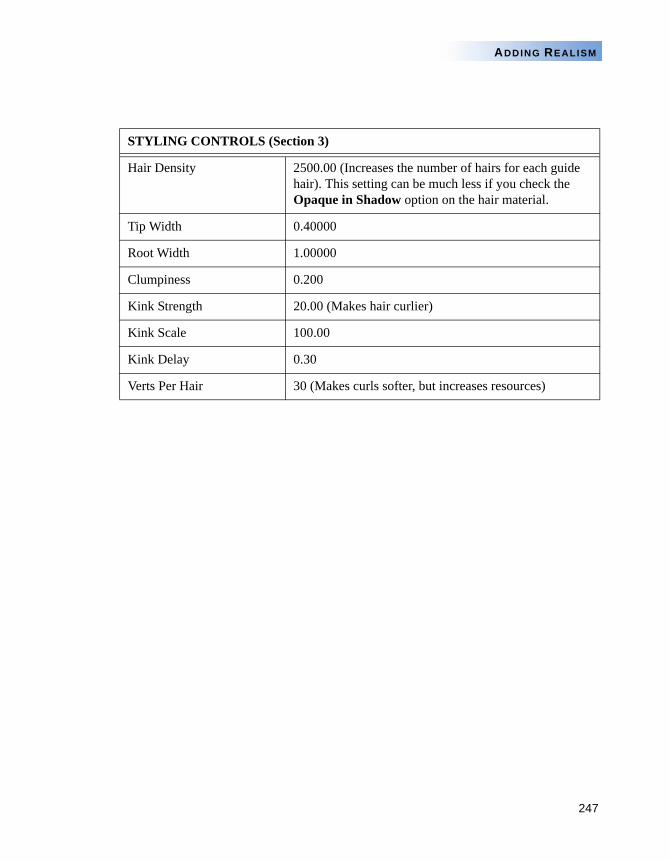
247
ADDING REALISM
STYLING CONTROLS (Section 3)
Hair Density 2500.00 (Increases the number of hairs for each guide hair). This setting can be much less if you check the Opaque in Shadow option on the hair material.
Tip Width 0.40000
Root Width 1.00000
Clumpiness 0.200
Kink Strength 20.00 (Makes hair curlier)
Kink Scale 100.00
Kink Delay 0.30
Verts Per Hair 30 (Makes curls softer, but increases resources)
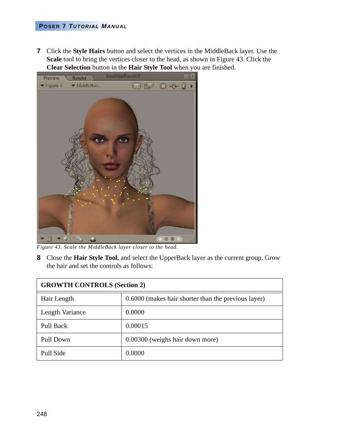
248
POSER 7 TUTORIAL MANUAL
7 Click the Style Hairs button and select the vertices in the MiddleBack layer. Use the Scale tool to bring the vertices closer to the head, as shown in Figure 43. Click the Clear Selection button in the Hair Style Tool when you are finished.
Figure 43. Scale the MiddleBack layer closer to the head.
8 Close the Hair Style Tool, and select the UpperBack layer as the current group. Grow the hair and set the controls as follows:
GROWTH CONTROLS (Section 2)
Hair Length 0.6000 (makes hair shorter than the previous layer)
Length Variance 0.0000
Pull Back 0.00015
Pull Down 0.00300 (weighs hair down more)
Pull Side 0.0000
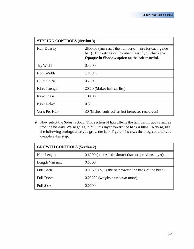
249
ADDING REALISM
9 Now select the Sides section. This section of hair affects the hair that is above and in front of the ears. We’re going to pull this layer toward the back a little. To do so, use the following settings after you grow the hair. Figure 44 shows the progress after you complete this step.
STYLING CONTROLS (Section 3)
Hair Density 2500.00 (Increases the number of hairs for each guide hair). This setting can be much less if you check the Opaque in Shadow option on the hair material.
Tip Width 0.40000
Root Width 1.00000
Clumpiness 0.200
Kink Strength 20.00 (Makes hair curlier)
Kink Scale 100.00
Kink Delay 0.30
Verts Per Hair 30 (Makes curls softer, but increases resources)
GROWTH CONTROLS (Section 2)
Hair Length 0.6000 (makes hair shorter than the previous layer)
Length Variance 0.0000
Pull Back 0.00600 (pulls the hair toward the back of the head)
Pull Down 0.00250 (weighs hair down more)
Pull Side 0.0000
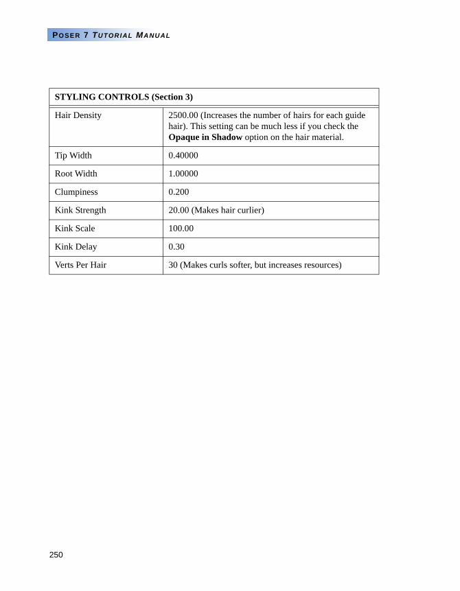
250
POSER 7 TUTORIAL MANUAL
STYLING CONTROLS (Section 3)
Hair Density 2500.00 (Increases the number of hairs for each guide hair). This setting can be much less if you check the Opaque in Shadow option on the hair material.
Tip Width 0.40000
Root Width 1.00000
Clumpiness 0.200
Kink Strength 20.00 (Makes hair curlier)
Kink Scale 100.00
Kink Delay 0.30
Verts Per Hair 30 (Makes curls softer, but increases resources)
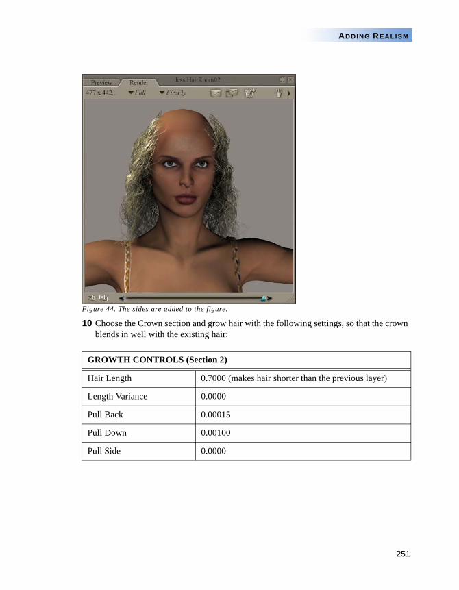
251
ADDING REALISM
Figure 44. The sides are added to the figure.
10 Choose the Crown section and grow hair with the following settings, so that the crown blends in well with the existing hair:
GROWTH CONTROLS (Section 2)
Hair Length 0.7000 (makes hair shorter than the previous layer)
Length Variance 0.0000
Pull Back 0.00015
Pull Down 0.00100
Pull Side 0.0000
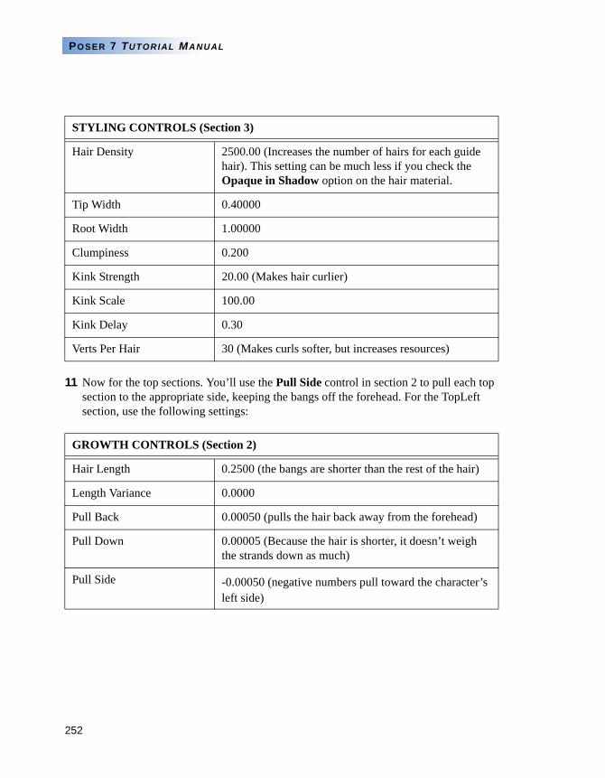
252
POSER 7 TUTORIAL MANUAL
11 Now for the top sections. You’ll use the Pull Side control in section 2 to pull each top section to the appropriate side, keeping the bangs off the forehead. For the TopLeft section, use the following settings:
STYLING CONTROLS (Section 3)
Hair Density 2500.00 (Increases the number of hairs for each guide hair). This setting can be much less if you check the Opaque in Shadow option on the hair material.
Tip Width 0.40000
Root Width 1.00000
Clumpiness 0.200
Kink Strength 20.00 (Makes hair curlier)
Kink Scale 100.00
Kink Delay 0.30
Verts Per Hair 30 (Makes curls softer, but increases resources)
GROWTH CONTROLS (Section 2)
Hair Length 0.2500 (the bangs are shorter than the rest of the hair)
Length Variance 0.0000
Pull Back 0.00050 (pulls the hair back away from the forehead)
Pull Down 0.00005 (Because the hair is shorter, it doesn’t weigh the strands down as much)
Pull Side -0.00050 (negative numbers pull toward the character’s left side)
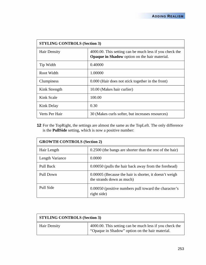
253
ADDING REALISM
12 For the TopRight, the settings are almost the same as the TopLeft. The only difference is the PullSide setting, which is now a positive number:
STYLING CONTROLS (Section 3)
Hair Density 4000.00. This setting can be much less if you check the Opaque in Shadow option on the hair material.
Tip Width 0.40000
Root Width 1.00000
Clumpiness 0.000 (Hair does not stick together in the front)
Kink Strength 10.00 (Makes hair curlier)
Kink Scale 100.00
Kink Delay 0.30
Verts Per Hair 30 (Makes curls softer, but increases resources)
GROWTH CONTROLS (Section 2)
Hair Length 0.2500 (the bangs are shorter than the rest of the hair)
Length Variance 0.0000
Pull Back 0.00050 (pulls the hair back away from the forehead)
Pull Down 0.00005 (Because the hair is shorter, it doesn’t weigh the strands down as much)
Pull Side 0.00050 (positive numbers pull toward the character’s right side)
STYLING CONTROLS (Section 3)
Hair Density 4000.00. This setting can be much less if you check the “Opaque in Shadow” option on the hair material.
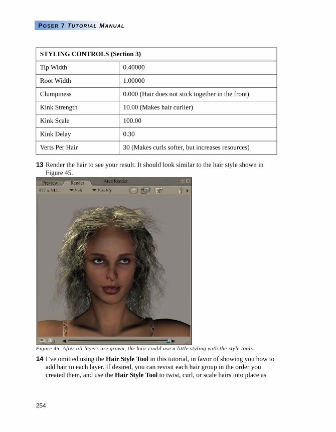
254
POSER 7 TUTORIAL MANUAL
13 Render the hair to see your result. It should look similar to the hair style shown in Figure 45.
Figure 45. After all layers are grown, the hair could use a little styling with the style tools.
14 I’ve omitted using the Hair Style Tool in this tutorial, in favor of showing you how to add hair to each layer. If desired, you can revisit each hair group in the order you created them, and use the Hair Style Tool to twist, curl, or scale hairs into place as
Tip Width 0.40000
Root Width 1.00000
Clumpiness 0.000 (Hair does not stick together in the front)
Kink Strength 10.00 (Makes hair curlier)
Kink Scale 100.00
Kink Delay 0.30
Verts Per Hair 30 (Makes curls softer, but increases resources)
STYLING CONTROLS (Section 3)
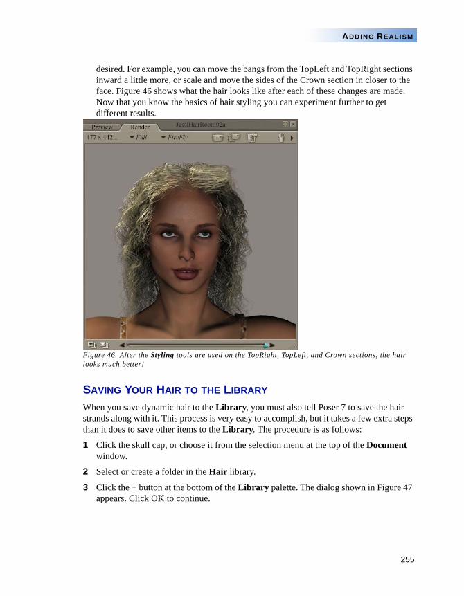
255
ADDING REALISM
desired. For example, you can move the bangs from the TopLeft and TopRight sections inward a little more, or scale and move the sides of the Crown section in closer to the face. Figure 46 shows what the hair looks like after each of these changes are made. Now that you know the basics of hair styling you can experiment further to get different results.
Figure 46. After the Styling tools are used on the TopRight, TopLeft, and Crown sections, the hair looks much better!
SAVING YOUR HAIR TO THE LIBRARY
When you save dynamic hair to the Library, you must also tell Poser 7 to save the hair strands along with it. This process is very easy to accomplish, but it takes a few extra steps than it does to save other items to the Library. The procedure is as follows:
1 Click the skull cap, or choose it from the selection menu at the top of the Document window.
2 Select or create a folder in the Hair library.
3 Click the + button at the bottom of the Library palette. The dialog shown in Figure 47 appears. Click OK to continue.
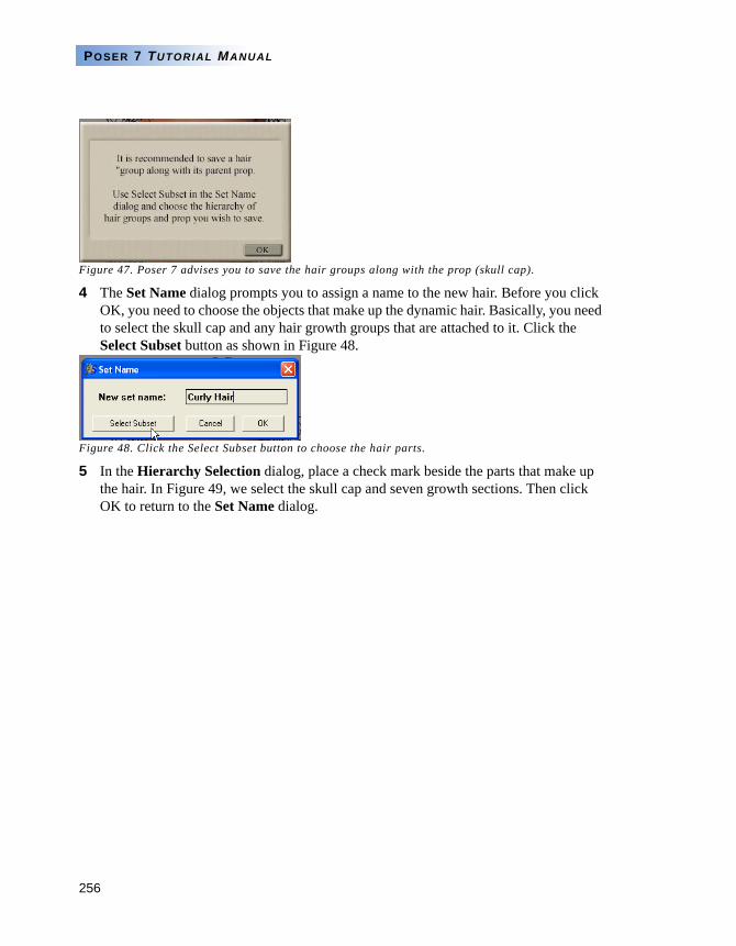
256
POSER 7 TUTORIAL MANUAL
Figure 47. Poser 7 advises you to save the hair groups along with the prop (skull cap).
4 The Set Name dialog prompts you to assign a name to the new hair. Before you click OK, you need to choose the objects that make up the dynamic hair. Basically, you need to select the skull cap and any hair growth groups that are attached to it. Click the Select Subset button as shown in Figure 48.
Figure 48. Click the Select Subset button to choose the hair parts.
5 In the Hierarchy Selection dialog, place a check mark beside the parts that make up the hair. In Figure 49, we select the skull cap and seven growth sections. Then click OK to return to the Set Name dialog.
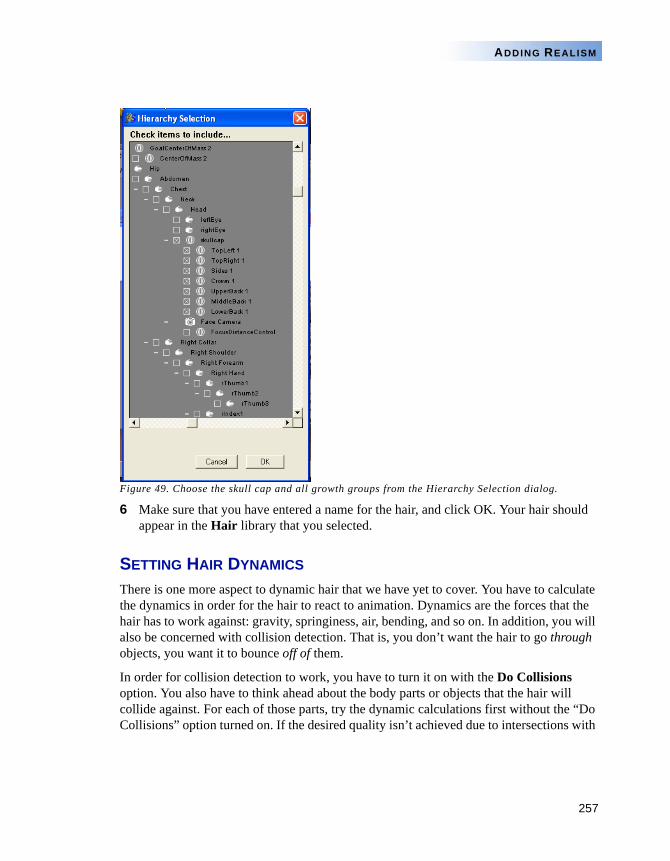
257
ADDING REALISM
Figure 49. Choose the skull cap and all growth groups from the Hierarchy Selection dialog.
6 Make sure that you have entered a name for the hair, and click OK. Your hair should appear in the Hair library that you selected.
SETTING HAIR DYNAMICS
There is one more aspect to dynamic hair that we have yet to cover. You have to calculate the dynamics in order for the hair to react to animation. Dynamics are the forces that the hair has to work against: gravity, springiness, air, bending, and so on. In addition, you will also be concerned with collision detection. That is, you don’t want the hair to go through objects, you want it to bounce off of them.
In order for collision detection to work, you have to turn it on with the Do Collisions option. You also have to think ahead about the body parts or objects that the hair will collide against. For each of those parts, try the dynamic calculations first without the “Do Collisions” option turned on. If the desired quality isn’t achieved due to intersections with
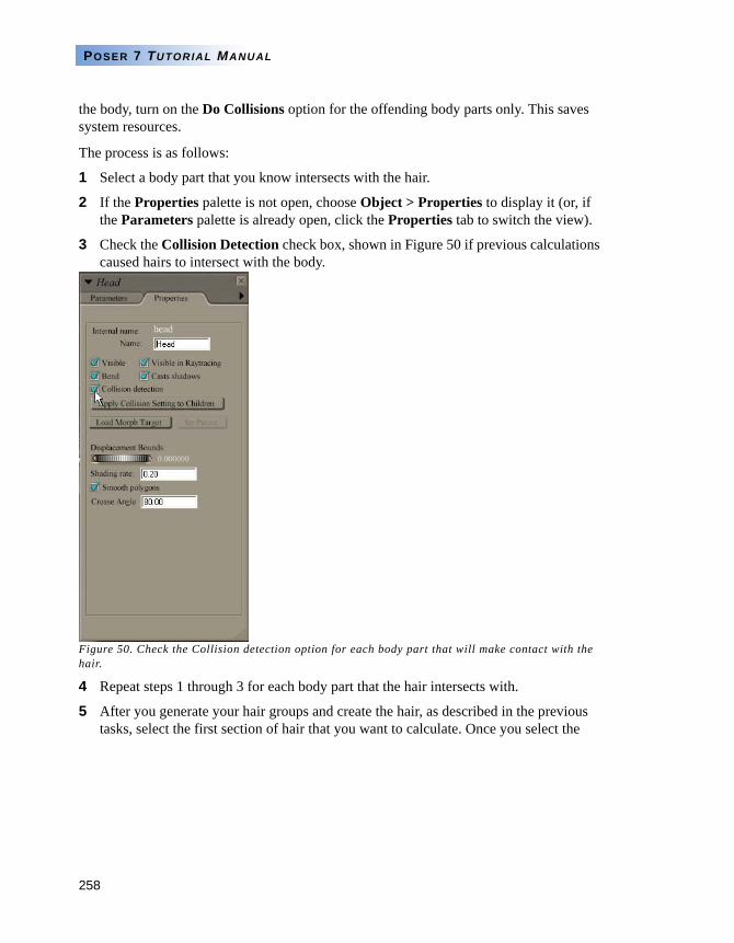
258
POSER 7 TUTORIAL MANUAL
the body, turn on the Do Collisions option for the offending body parts only. This saves system resources.
The process is as follows:
1 Select a body part that you know intersects with the hair.
2 If the Properties palette is not open, choose Object > Properties to display it (or, if the Parameters palette is already open, click the Properties tab to switch the view).
3 Check the Collision Detection check box, shown in Figure 50 if previous calculations caused hairs to intersect with the body.
Figure 50. Check the Collision detection option for each body part that will make contact with the hair.
4 Repeat steps 1 through 3 for each body part that the hair intersects with.
5 After you generate your hair groups and create the hair, as described in the previous tasks, select the first section of hair that you want to calculate. Once you select the
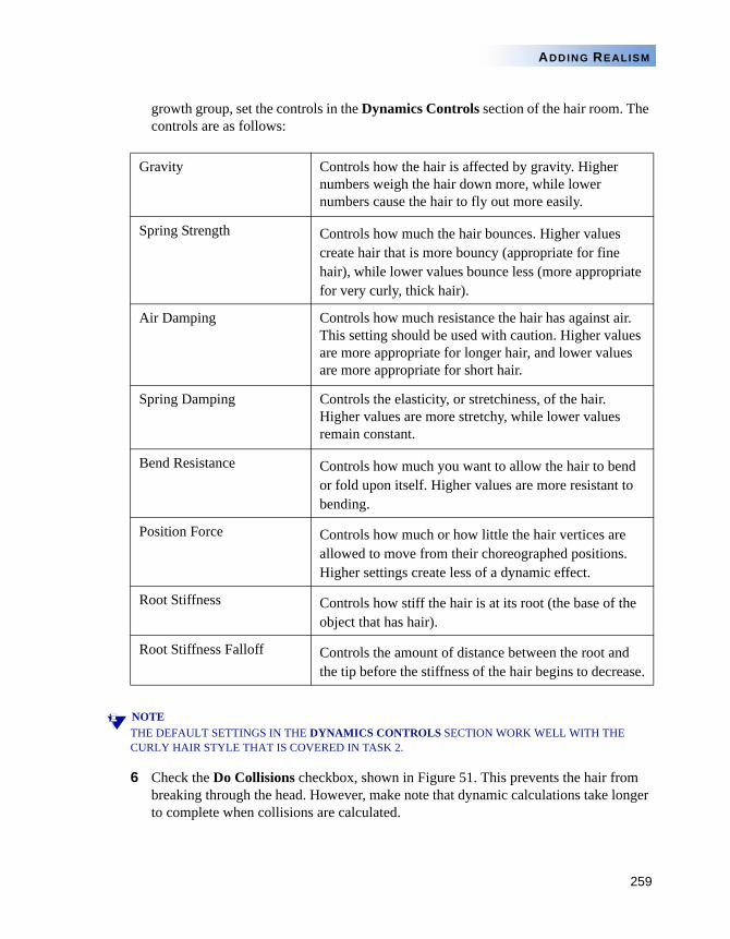
259
ADDING REALISM
growth group, set the controls in the Dynamics Controls section of the hair room. The controls are as follows:
NOTETHE DEFAULT SETTINGS IN THE DYNAMICS CONTROLS SECTION WORK WELL WITH THE CURLY HAIR STYLE THAT IS COVERED IN TASK 2.
6 Check the Do Collisions checkbox, shown in Figure 51. This prevents the hair from breaking through the head. However, make note that dynamic calculations take longer to complete when collisions are calculated.
Gravity Controls how the hair is affected by gravity. Higher numbers weigh the hair down more, while lower numbers cause the hair to fly out more easily.
Spring Strength Controls how much the hair bounces. Higher values create hair that is more bouncy (appropriate for fine hair), while lower values bounce less (more appropriate for very curly, thick hair).
Air Damping Controls how much resistance the hair has against air. This setting should be used with caution. Higher values are more appropriate for longer hair, and lower values are more appropriate for short hair.
Spring Damping Controls the elasticity, or stretchiness, of the hair. Higher values are more stretchy, while lower values remain constant.
Bend Resistance Controls how much you want to allow the hair to bend or fold upon itself. Higher values are more resistant to bending.
Position Force Controls how much or how little the hair vertices are allowed to move from their choreographed positions. Higher settings create less of a dynamic effect.
Root Stiffness Controls how stiff the hair is at its root (the base of the object that has hair).
Root Stiffness Falloff Controls the amount of distance between the root and the tip before the stiffness of the hair begins to decrease.
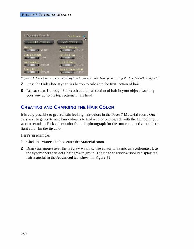
260
POSER 7 TUTORIAL MANUAL
Figure 51. Check the Do collisions option to prevent hair from penetrating the head or other objects.
7 Press the Calculate Dynamics button to calculate the first section of hair.
8 Repeat steps 1 through 3 for each additional section of hair in your object, working your way up to the top sections in the head.
CREATING AND CHANGING THE HAIR COLOR
It is very possible to get realistic looking hair colors in the Poser 7 Material room. One easy way to generate nice hair colors is to find a color photograph with the hair color you want to emulate. Pick a dark color from the photograph for the root color, and a middle or light color for the tip color.
Here's an example:
1 Click the Material tab to enter the Material room.
2 Drag your mouse over the preview window. The cursor turns into an eyedropper. Use the eyedropper to select a hair growth group. The Shader window should display the hair material in the Advanced tab, shown in Figure 52.
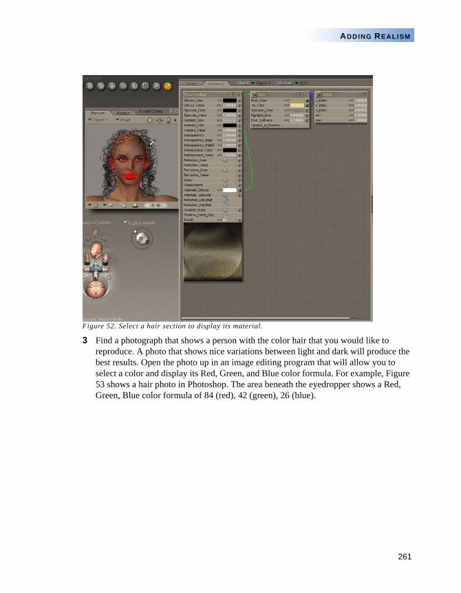
261
ADDING REALISM
Figure 52. Select a hair section to display its material.
3 Find a photograph that shows a person with the color hair that you would like to reproduce. A photo that shows nice variations between light and dark will produce the best results. Open the photo up in an image editing program that will allow you to select a color and display its Red, Green, and Blue color formula. For example, Figure 53 shows a hair photo in Photoshop. The area beneath the eyedropper shows a Red, Green, Blue color formula of 84 (red), 42 (green), 26 (blue).
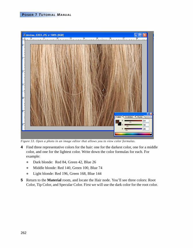
262
POSER 7 TUTORIAL MANUAL
Figure 53. Open a photo in an image editor that allows you to view color formulas.
4 Find three representative colors for the hair: one for the darkest color, one for a middle color, and one for the lightest color. Write down the color formulas for each. For example:
Dark blonde: Red 84, Green 42, Blue 26Middle blonde: Red 140, Green 100, Blue 74Light blonde: Red 196, Green 168, Blue 144
5 Return to the Material room, and locate the Hair node. You’ll see three colors: Root Color, Tip Color, and Specular Color. First we will use the dark color for the root color.
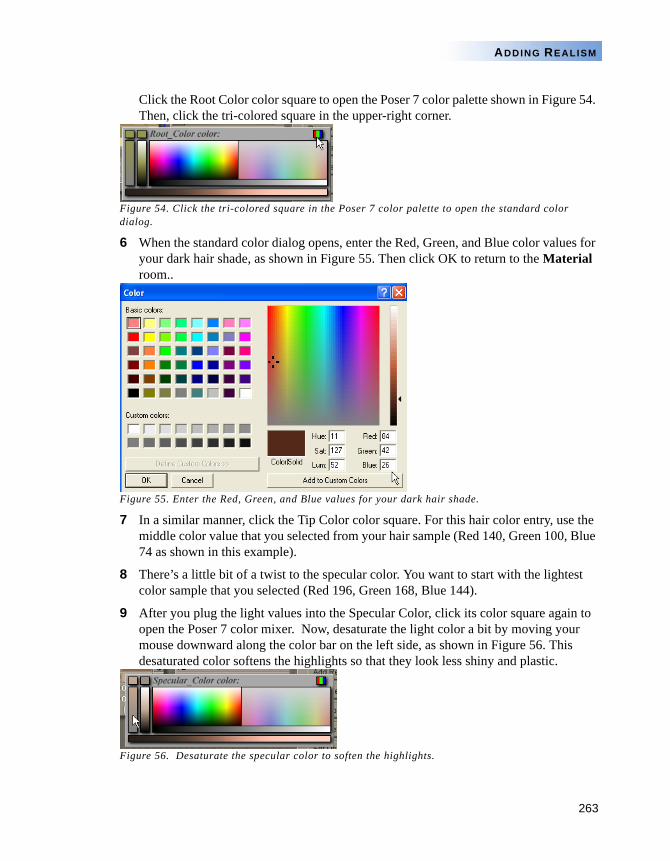
263
ADDING REALISM
Click the Root Color color square to open the Poser 7 color palette shown in Figure 54. Then, click the tri-colored square in the upper-right corner.
Figure 54. Click the tri-colored square in the Poser 7 color palette to open the standard color dialog.
6 When the standard color dialog opens, enter the Red, Green, and Blue color values for your dark hair shade, as shown in Figure 55. Then click OK to return to the Material room..
Figure 55. Enter the Red, Green, and Blue values for your dark hair shade.
7 In a similar manner, click the Tip Color color square. For this hair color entry, use the middle color value that you selected from your hair sample (Red 140, Green 100, Blue 74 as shown in this example).
8 There’s a little bit of a twist to the specular color. You want to start with the lightest color sample that you selected (Red 196, Green 168, Blue 144).
9 After you plug the light values into the Specular Color, click its color square again to open the Poser 7 color mixer. Now, desaturate the light color a bit by moving your mouse downward along the color bar on the left side, as shown in Figure 56. This desaturated color softens the highlights so that they look less shiny and plastic.
Figure 56. Desaturate the specular color to soften the highlights.
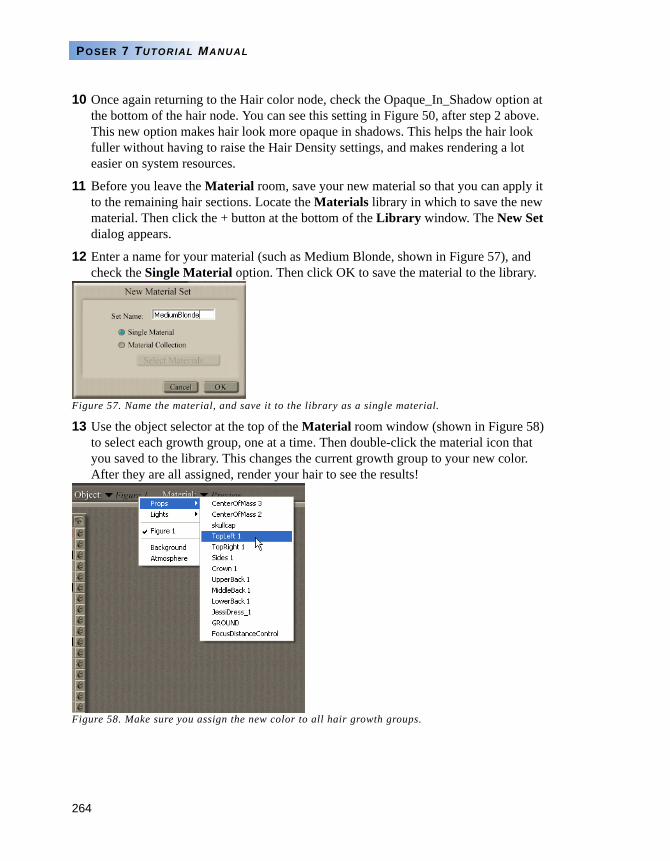
264
POSER 7 TUTORIAL MANUAL
10 Once again returning to the Hair color node, check the Opaque_In_Shadow option at the bottom of the hair node. You can see this setting in Figure 50, after step 2 above. This new option makes hair look more opaque in shadows. This helps the hair look fuller without having to raise the Hair Density settings, and makes rendering a lot easier on system resources.
11 Before you leave the Material room, save your new material so that you can apply it to the remaining hair sections. Locate the Materials library in which to save the new material. Then click the + button at the bottom of the Library window. The New Set dialog appears.
12 Enter a name for your material (such as Medium Blonde, shown in Figure 57), and check the Single Material option. Then click OK to save the material to the library.
Figure 57. Name the material, and save it to the library as a single material.
13 Use the object selector at the top of the Material room window (shown in Figure 58) to select each growth group, one at a time. Then double-click the material icon that you saved to the library. This changes the current growth group to your new color. After they are all assigned, render your hair to see the results!
Figure 58. Make sure you assign the new color to all hair growth groups.
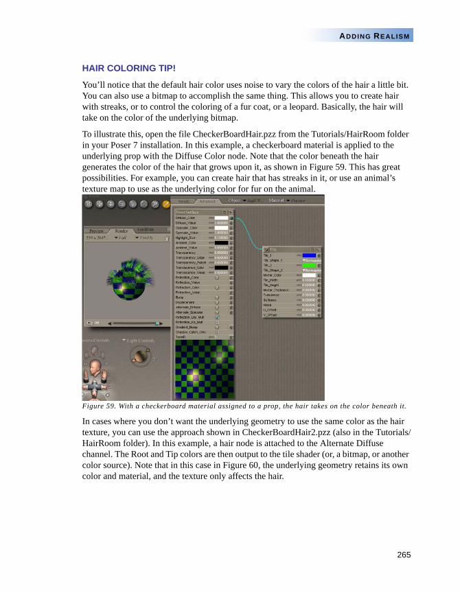
265
ADDING REALISM
HAIR COLORING TIP!
You’ll notice that the default hair color uses noise to vary the colors of the hair a little bit. You can also use a bitmap to accomplish the same thing. This allows you to create hair with streaks, or to control the coloring of a fur coat, or a leopard. Basically, the hair will take on the color of the underlying bitmap.
To illustrate this, open the file CheckerBoardHair.pzz from the Tutorials/HairRoom folder in your Poser 7 installation. In this example, a checkerboard material is applied to the underlying prop with the Diffuse Color node. Note that the color beneath the hair generates the color of the hair that grows upon it, as shown in Figure 59. This has great possibilities. For example, you can create hair that has streaks in it, or use an animal’s texture map to use as the underlying color for fur on the animal.
Figure 59. With a checkerboard material assigned to a prop, the hair takes on the color beneath it.
In cases where you don’t want the underlying geometry to use the same color as the hair texture, you can use the approach shown in CheckerBoardHair2.pzz (also in the Tutorials/HairRoom folder). In this example, a hair node is attached to the Alternate Diffuse channel. The Root and Tip colors are then output to the tile shader (or, a bitmap, or another color source). Note that in this case in Figure 60, the underlying geometry retains its own color and material, and the texture only affects the hair.
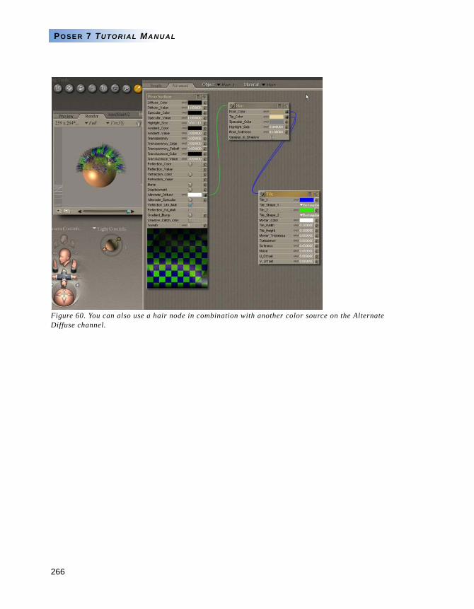
266
POSER 7 TUTORIAL MANUAL
Figure 60. You can also use a hair node in combination with another color source on the Alternate Diffuse channel.
267
ADDING REALISM
Chapter 13: Building a Basic Skin Shader
by Kiera Wooley
NOTE ON WORKFLOW
There is a definite relationship between the FireFly render options, the Material room, and the lighting in any Poser 7 scene. Changes to any one of these elements might necessitate changes to the others. When developing a scene that will be rendered as a still image, it is generally easiest to compose the scene, create an appropriate lighting arrangement, and then tweak materials to suit the environment. Polishing the render will generally involve making adjustments to the lights, materials, and render options all at once. Because of these workflow concerns, any tutorial involving the Material room should be viewed as a general guideline rather than a definite recipe for a specific result.
ADVANCED MATERIALS
For the purpose of this tutorial, we will be using the Advanced tab to take advantage of the more complex nodes and their ability to interact more deeply with scene lighting and the FireFly renderer. If you are unfamiliar with the basic operation of shader nodes in Poser 7, please review the Materials section in the Poser 7 Reference Manual.
GETTING STARTED
We will use James for this tutorial. Load James from the Figures library and switch to the Material room. Select the Advanced tab. Mouse over the miniature Document window and use the eyedropper to select any part of the skin to display the basic shader. Connected to the Diffuse_Color node is James’ texture map, which defines the color of his skin when displayed under a pure white light. We shall use this map (and his other texture maps) as the basis for our skin shader.
A
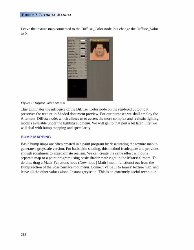
268
POSER 7 TUTORIAL MANUAL
Leave the texture map connected to the Diffuse_Color node, but change the Diffuse_Value to 0.
Figure 1: Diffuse_Value set to 0
This eliminates the influence of the Diffuse_Color node on the rendered output but preserves the texture in Shaded document preview. For our purposes we shall employ the Alternate_Diffuse node, which allows us to access the more complex and realistic lighting models available under the lighting submenu. We will get to that part a bit later. First we will deal with bump mapping and specularity.
BUMP MAPPING
Basic bump maps are often created in a paint program by desaturating the texture map to generate a greyscale version. For basic skin shading, this method is adequate and provides enough roughness to approximate realism. We can create the same effect without a separate map or a paint program using basic shader math right in the Material room. To do this, drag a Math_Functions node (New node | Math | math_functions) out from the Bump section of the PoserSurface root menu. Connect Value_1 to James’ texture map, and leave all the other values alone. Instant greyscale! This is an extremely useful technique
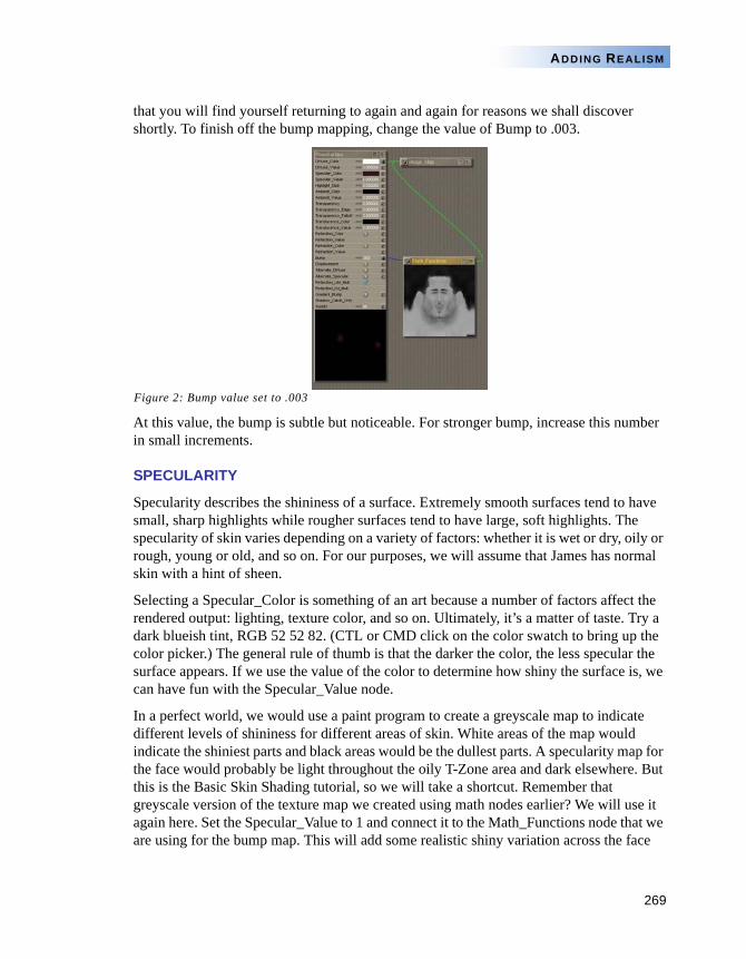
269
ADDING REALISM
that you will find yourself returning to again and again for reasons we shall discover shortly. To finish off the bump mapping, change the value of Bump to .003.
Figure 2: Bump value set to .003
At this value, the bump is subtle but noticeable. For stronger bump, increase this number in small increments.
SPECULARITY
Specularity describes the shininess of a surface. Extremely smooth surfaces tend to have small, sharp highlights while rougher surfaces tend to have large, soft highlights. The specularity of skin varies depending on a variety of factors: whether it is wet or dry, oily or rough, young or old, and so on. For our purposes, we will assume that James has normal skin with a hint of sheen.
Selecting a Specular_Color is something of an art because a number of factors affect the rendered output: lighting, texture color, and so on. Ultimately, it’s a matter of taste. Try a dark blueish tint, RGB 52 52 82. (CTL or CMD click on the color swatch to bring up the color picker.) The general rule of thumb is that the darker the color, the less specular the surface appears. If we use the value of the color to determine how shiny the surface is, we can have fun with the Specular_Value node.
In a perfect world, we would use a paint program to create a greyscale map to indicate different levels of shininess for different areas of skin. White areas of the map would indicate the shiniest parts and black areas would be the dullest parts. A specularity map for the face would probably be light throughout the oily T-Zone area and dark elsewhere. But this is the Basic Skin Shading tutorial, so we will take a shortcut. Remember that greyscale version of the texture map we created using math nodes earlier? We will use it again here. Set the Specular_Value to 1 and connect it to the Math_Functions node that we are using for the bump map. This will add some realistic shiny variation across the face
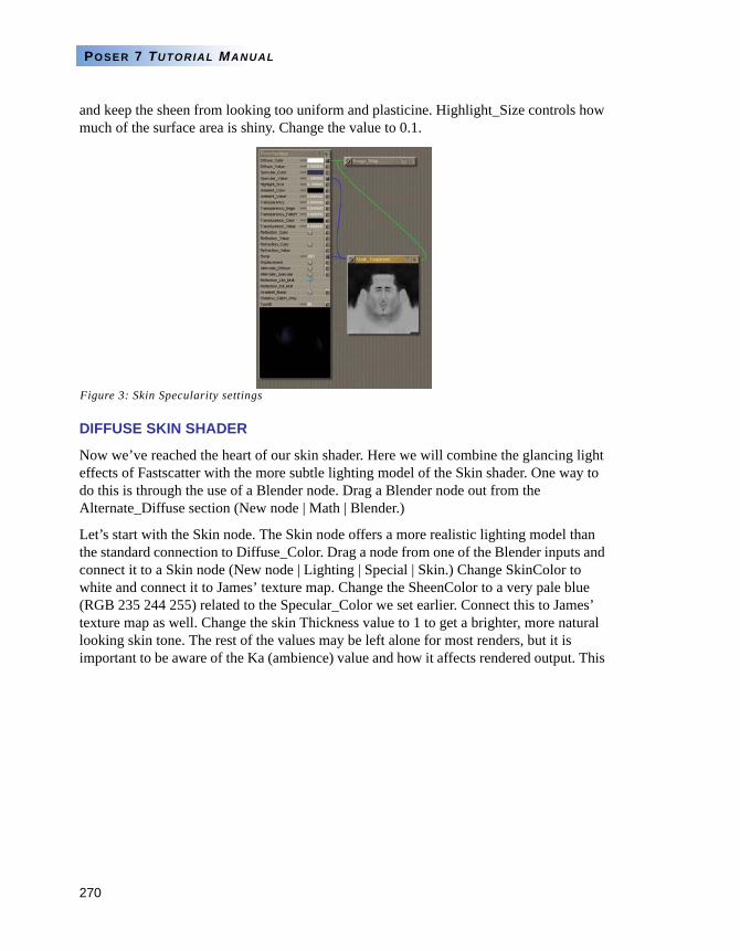
270
POSER 7 TUTORIAL MANUAL
and keep the sheen from looking too uniform and plasticine. Highlight_Size controls how much of the surface area is shiny. Change the value to 0.1.
Figure 3: Skin Specularity settings
DIFFUSE SKIN SHADER
Now we’ve reached the heart of our skin shader. Here we will combine the glancing light effects of Fastscatter with the more subtle lighting model of the Skin shader. One way to do this is through the use of a Blender node. Drag a Blender node out from the Alternate_Diffuse section (New node | Math | Blender.)
Let’s start with the Skin node. The Skin node offers a more realistic lighting model than the standard connection to Diffuse_Color. Drag a node from one of the Blender inputs and connect it to a Skin node (New node | Lighting | Special | Skin.) Change SkinColor to white and connect it to James’ texture map. Change the SheenColor to a very pale blue (RGB 235 244 255) related to the Specular_Color we set earlier. Connect this to James’ texture map as well. Change the skin Thickness value to 1 to get a brighter, more natural looking skin tone. The rest of the values may be left alone for most renders, but it is important to be aware of the Ka (ambience) value and how it affects rendered output. This
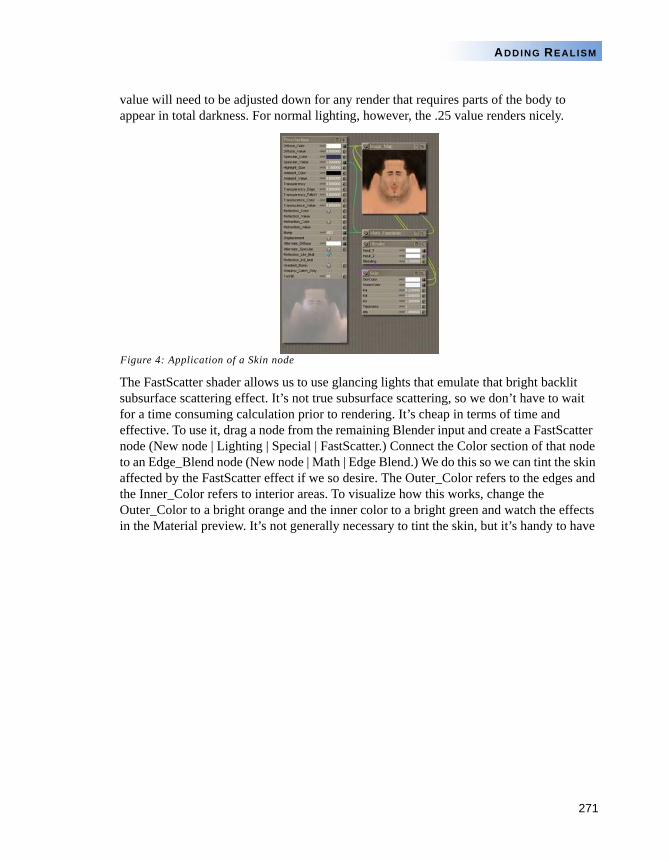
271
ADDING REALISM
value will need to be adjusted down for any render that requires parts of the body to appear in total darkness. For normal lighting, however, the .25 value renders nicely.
Figure 4: Application of a Skin node
The FastScatter shader allows us to use glancing lights that emulate that bright backlit subsurface scattering effect. It’s not true subsurface scattering, so we don’t have to wait for a time consuming calculation prior to rendering. It’s cheap in terms of time and effective. To use it, drag a node from the remaining Blender input and create a FastScatter node (New node | Lighting | Special | FastScatter.) Connect the Color section of that node to an Edge_Blend node (New node | Math | Edge Blend.) We do this so we can tint the skin affected by the FastScatter effect if we so desire. The Outer_Color refers to the edges and the Inner_Color refers to interior areas. To visualize how this works, change the Outer_Color to a bright orange and the inner color to a bright green and watch the effects in the Material preview. It’s not generally necessary to tint the skin, but it’s handy to have
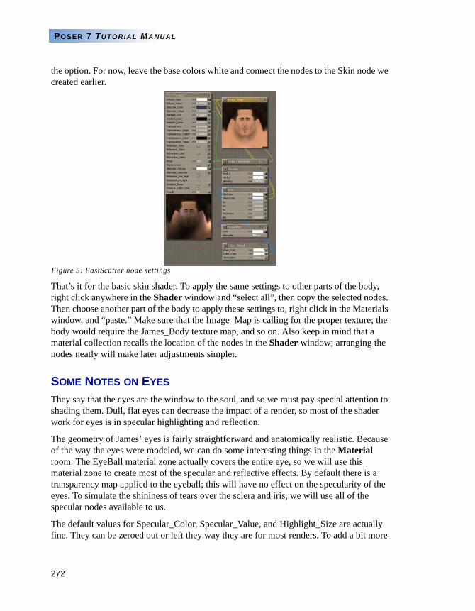
272
POSER 7 TUTORIAL MANUAL
the option. For now, leave the base colors white and connect the nodes to the Skin node we created earlier.
Figure 5: FastScatter node settings
That’s it for the basic skin shader. To apply the same settings to other parts of the body, right click anywhere in the Shader window and “select all”, then copy the selected nodes. Then choose another part of the body to apply these settings to, right click in the Materials window, and “paste.” Make sure that the Image_Map is calling for the proper texture; the body would require the James_Body texture map, and so on. Also keep in mind that a material collection recalls the location of the nodes in the Shader window; arranging the nodes neatly will make later adjustments simpler.
SOME NOTES ON EYES
They say that the eyes are the window to the soul, and so we must pay special attention to shading them. Dull, flat eyes can decrease the impact of a render, so most of the shader work for eyes is in specular highlighting and reflection.
The geometry of James’ eyes is fairly straightforward and anatomically realistic. Because of the way the eyes were modeled, we can do some interesting things in the Material room. The EyeBall material zone actually covers the entire eye, so we will use this material zone to create most of the specular and reflective effects. By default there is a transparency map applied to the eyeball; this will have no effect on the specularity of the eyes. To simulate the shininess of tears over the sclera and iris, we will use all of the specular nodes available to us.
The default values for Specular_Color, Specular_Value, and Highlight_Size are actually fine. They can be zeroed out or left they way they are for most renders. To add a bit more
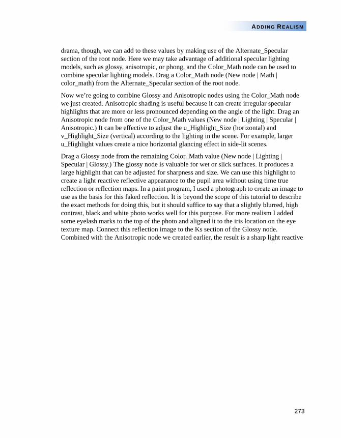
273
ADDING REALISM
drama, though, we can add to these values by making use of the Alternate_Specular section of the root node. Here we may take advantage of additional specular lighting models, such as glossy, anisotropic, or phong, and the Color_Math node can be used to combine specular lighting models. Drag a Color_Math node (New node | Math | color_math) from the Alternate_Specular section of the root node.
Now we’re going to combine Glossy and Anisotropic nodes using the Color_Math node we just created. Anisotropic shading is useful because it can create irregular specular highlights that are more or less pronounced depending on the angle of the light. Drag an Anisotropic node from one of the Color_Math values (New node | Lighting | Specular | Anisotropic.) It can be effective to adjust the u_Highlight_Size (horizontal) and v_Highlight_Size (vertical) according to the lighting in the scene. For example, larger u_Highlight values create a nice horizontal glancing effect in side-lit scenes.
Drag a Glossy node from the remaining Color_Math value (New node | Lighting | Specular | Glossy.) The glossy node is valuable for wet or slick surfaces. It produces a large highlight that can be adjusted for sharpness and size. We can use this highlight to create a light reactive reflective appearance to the pupil area without using time true reflection or reflection maps. In a paint program, I used a photograph to create an image to use as the basis for this faked reflection. It is beyond the scope of this tutorial to describe the exact methods for doing this, but it should suffice to say that a slightly blurred, high contrast, black and white photo works well for this purpose. For more realism I added some eyelash marks to the top of the photo and aligned it to the iris location on the eye texture map. Connect this reflection image to the Ks section of the Glossy node. Combined with the Anisotropic node we created earlier, the result is a sharp light reactive
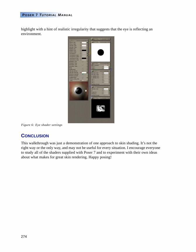
274
POSER 7 TUTORIAL MANUAL
highlight with a hint of realistic irregularity that suggests that the eye is reflecting an environment.
Figure 6: Eye shader settings
CONCLUSION
This walkthrough was just a demonstration of one approach to skin shading. It’s not the right way or the only way, and may not be useful for every situation. I encourage everyone to study all of the shaders supplied with Poser 7 and to experiment with their own ideas about what makes for great skin rendering. Happy posing!
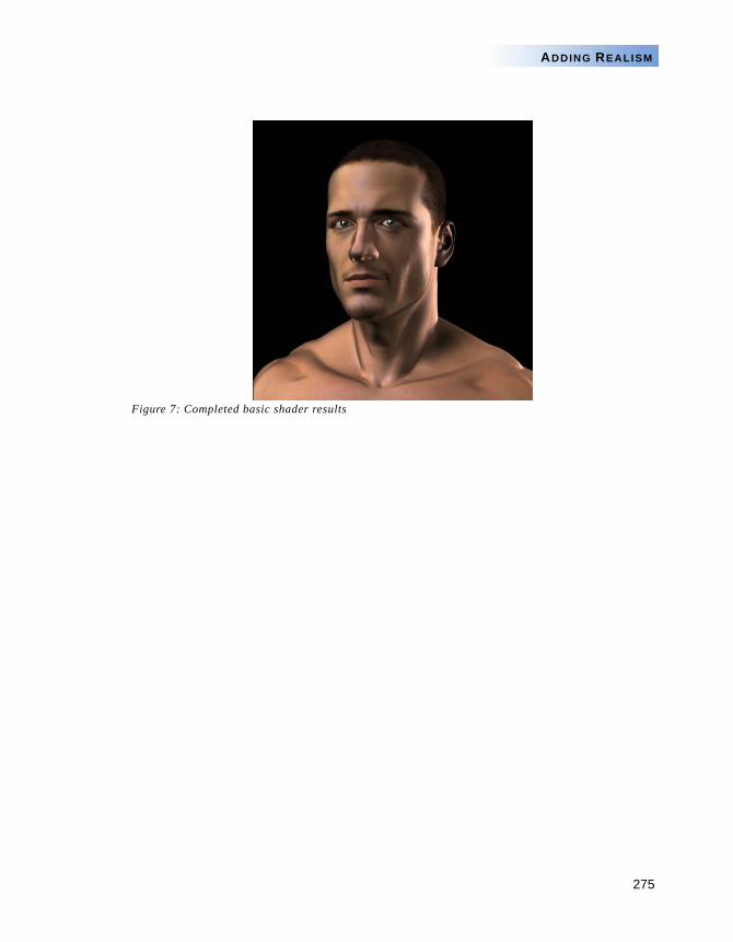
275
ADDING REALISM
Figure 7: Completed basic shader results
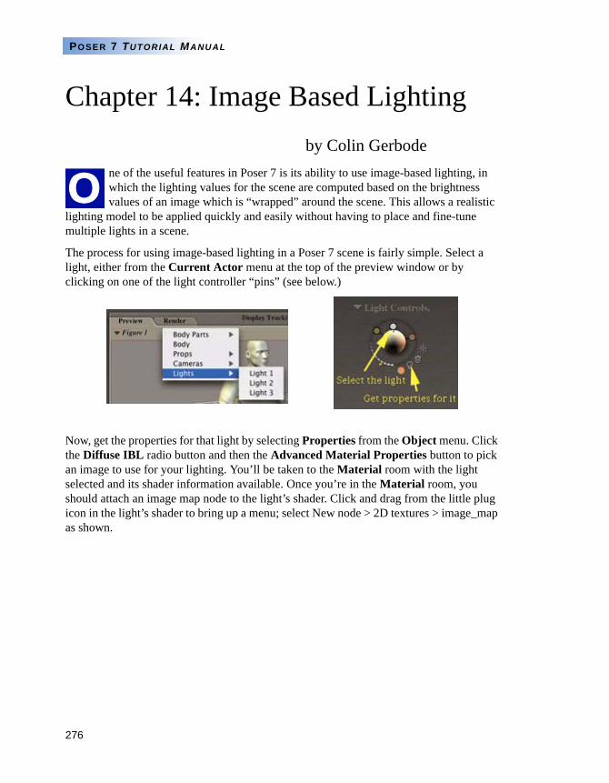
276
POSER 7 TUTORIAL MANUAL
Chapter 14: Image Based Lightingby Colin Gerbode
ne of the useful features in Poser 7 is its ability to use image-based lighting, in which the lighting values for the scene are computed based on the brightness values of an image which is “wrapped” around the scene. This allows a realistic
lighting model to be applied quickly and easily without having to place and fine-tune multiple lights in a scene.
The process for using image-based lighting in a Poser 7 scene is fairly simple. Select a light, either from the Current Actor menu at the top of the preview window or by clicking on one of the light controller “pins” (see below.)
Now, get the properties for that light by selecting Properties from the Object menu. Click the Diffuse IBL radio button and then the Advanced Material Properties button to pick an image to use for your lighting. You’ll be taken to the Material room with the light selected and its shader information available. Once you’re in the Material room, you should attach an image map node to the light’s shader. Click and drag from the little plug icon in the light’s shader to bring up a menu; select New node > 2D textures > image_map as shown.
O
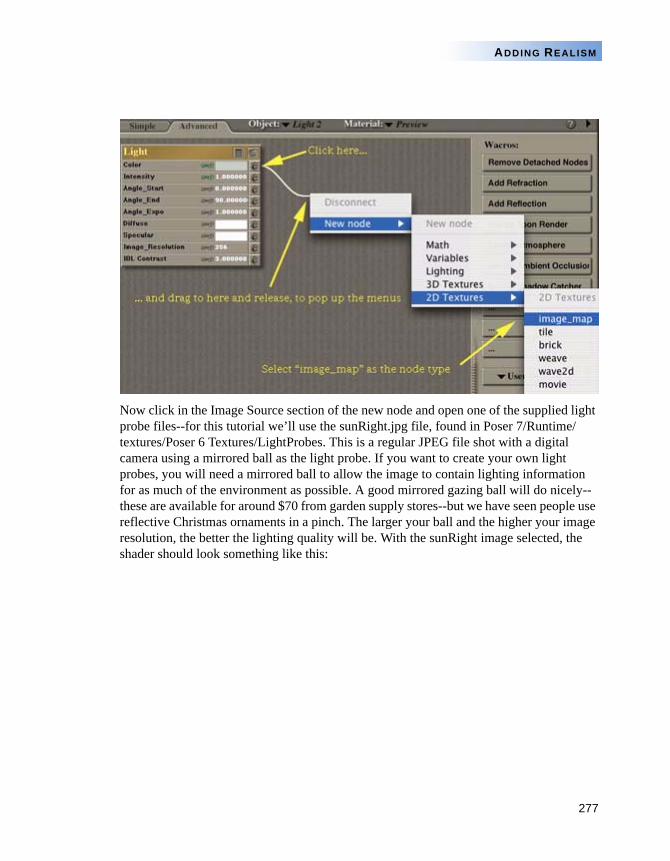
277
ADDING REALISM
Now click in the Image Source section of the new node and open one of the supplied light probe files--for this tutorial we’ll use the sunRight.jpg file, found in Poser 7/Runtime/textures/Poser 6 Textures/LightProbes. This is a regular JPEG file shot with a digital camera using a mirrored ball as the light probe. If you want to create your own light probes, you will need a mirrored ball to allow the image to contain lighting information for as much of the environment as possible. A good mirrored gazing ball will do nicely--these are available for around $70 from garden supply stores--but we have seen people use reflective Christmas ornaments in a pinch. The larger your ball and the higher your image resolution, the better the lighting quality will be. With the sunRight image selected, the shader should look something like this:
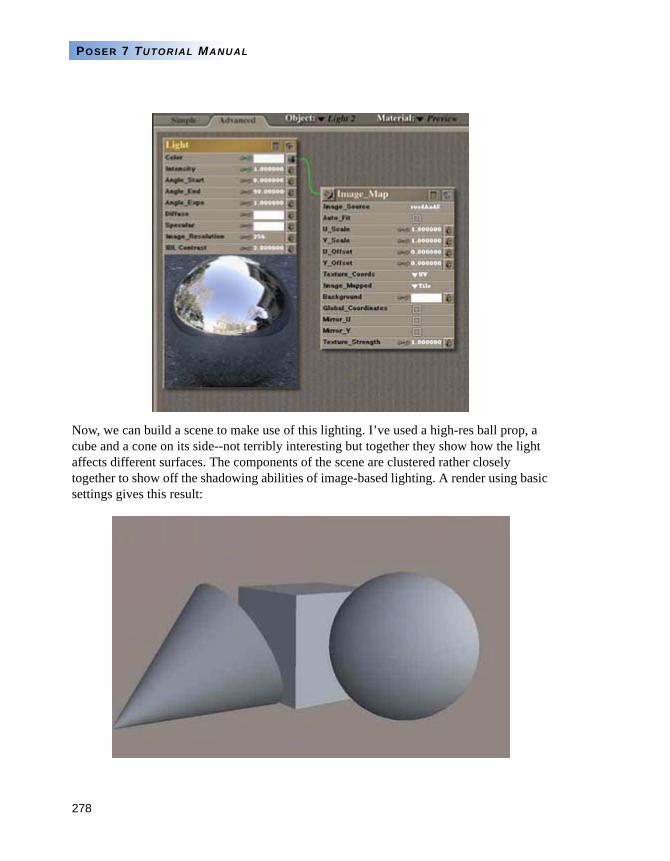
278
POSER 7 TUTORIAL MANUAL
Now, we can build a scene to make use of this lighting. I’ve used a high-res ball prop, a cube and a cone on its side--not terribly interesting but together they show how the light affects different surfaces. The components of the scene are clustered rather closely together to show off the shadowing abilities of image-based lighting. A render using basic settings gives this result:
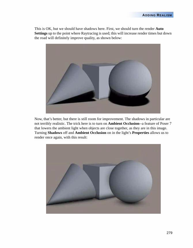
279
ADDING REALISM
This is OK, but we should have shadows here. First, we should turn the render Auto Settings up to the point where Raytracing is used; this will increase render times but down the road will definitely improve quality, as shown below:
Now, that’s better, but there is still room for improvement. The shadows in particular are not terribly realistic. The trick here is to turn on Ambient Occlusion--a feature of Poser 7 that lowers the ambient light when objects are close together, as they are in this image. Turning Shadows off and Ambient Occlusion on in the light’s Properties allows us to render once again, with this result:
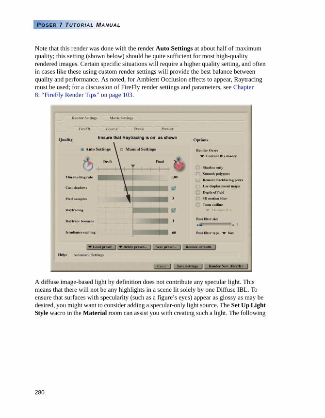
280
POSER 7 TUTORIAL MANUAL
Note that this render was done with the render Auto Settings at about half of maximum quality; this setting (shown below) should be quite sufficient for most high-quality rendered images. Certain specific situations will require a higher quality setting, and often in cases like these using custom render settings will provide the best balance between quality and performance. As noted, for Ambient Occlusion effects to appear, Raytracing must be used; for a discussion of FireFly render settings and parameters, see Chapter 8: “FireFly Render Tips” on page 103.
A diffuse image-based light by definition does not contribute any specular light. This means that there will not be any highlights in a scene lit solely by one Diffuse IBL. To ensure that surfaces with specularity (such as a figure’s eyes) appear as glossy as may be desired, you might want to consider adding a specular-only light source. The Set Up Light Style wacro in the Material room can assist you with creating such a light. The following
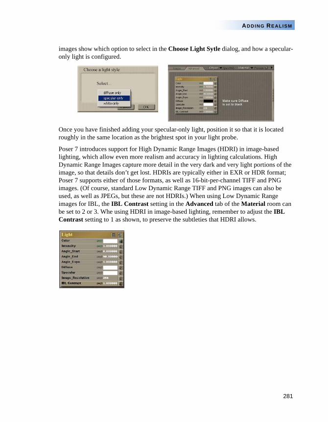
281
ADDING REALISM
images show which option to select in the Choose Light Sytle dialog, and how a specular-only light is configured.
Once you have finished adding your specular-only light, position it so that it is located roughly in the same location as the brightest spot in your light probe.
Poser 7 introduces support for High Dynamic Range Images (HDRI) in image-based lighting, which allow even more realism and accuracy in lighting calculations. High Dynamic Range Images capture more detail in the very dark and very light portions of the image, so that details don’t get lost. HDRIs are typically either in EXR or HDR format; Poser 7 supports either of those formats, as well as 16-bit-per-channel TIFF and PNG images. (Of course, standard Low Dynamic Range TIFF and PNG images can also be used, as well as JPEGs, but these are not HDRIs.) When using Low Dynamic Range images for IBL, the IBL Contrast setting in the Advanced tab of the Material room can be set to 2 or 3. Whe using HDRI in image-based lighting, remember to adjust the IBL Contrast setting to 1 as shown, to preserve the subtleties that HDRI allows.
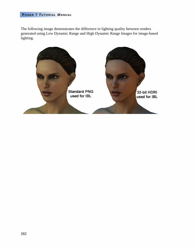
282
POSER 7 TUTORIAL MANUAL
The following image demonstrates the difference in lighting quality between renders generated using Low Dynamic Range and High Dynamic Range Images for image-based lighting.
PART 4
Posing andAnimation
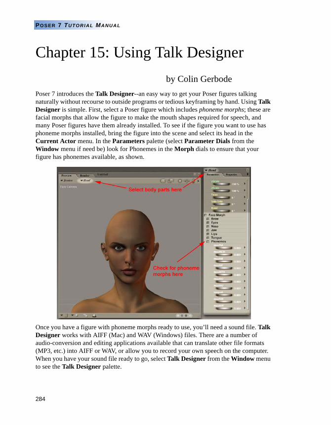
284
POSER 7 TUTORIAL MANUAL
Chapter 15: Using Talk Designerby Colin Gerbode
Poser 7 introduces the Talk Designer--an easy way to get your Poser figures talking naturally without recourse to outside programs or tedious keyframing by hand. Using Talk Designer is simple. First, select a Poser figure which includes phoneme morphs; these are facial morphs that allow the figure to make the mouth shapes required for speech, and many Poser figures have them already installed. To see if the figure you want to use has phoneme morphs installed, bring the figure into the scene and select its head in the Current Actor menu. In the Parameters palette (select Parameter Dials from the Window menu if need be) look for Phonemes in the Morph dials to ensure that your figure has phonemes available, as shown.
Once you have a figure with phoneme morphs ready to use, you’ll need a sound file. Talk Designer works with AIFF (Mac) and WAV (Windows) files. There are a number of audio-conversion and editing applications available that can translate other file formats (MP3, etc.) into AIFF or WAV, or allow you to record your own speech on the computer. When you have your sound file ready to go, select Talk Designer from the Window menu to see the Talk Designer palette.
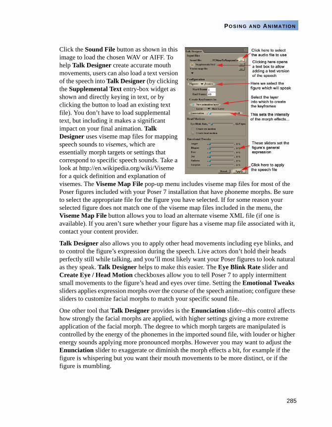
285
POSING AND ANIMATION
Click the Sound File button as shown in this image to load the chosen WAV or AIFF. To help Talk Designer create accurate mouth movements, users can also load a text version of the speech into Talk Designer (by clicking the Supplemental Text entry-box widget as shown and directly keying in text, or by clicking the button to load an existing text file). You don’t have to load supplemental text, but including it makes a significant impact on your final animation. Talk Designer uses viseme map files for mapping speech sounds to visemes, which are essentially morph targets or settings that correspond to specific speech sounds. Take a look at http://en.wikipedia.org/wiki/Viseme for a quick definition and explanation of visemes. The Viseme Map File pop-up menu includes viseme map files for most of the Poser figures included with your Poser 7 installation that have phoneme morphs. Be sure to select the appropriate file for the figure you have selected. If for some reason your selected figure does not match one of the viseme map files included in the menu, the Viseme Map File button allows you to load an alternate viseme XML file (if one is available). If you aren’t sure whether your figure has a viseme map file associated with it, contact your content provider.
Talk Designer also allows you to apply other head movements including eye blinks, and to control the figure’s expression during the speech. Live actors don’t hold their heads perfectly still while talking, and you’ll most likely want your Poser figures to look natural as they speak. Talk Designer helps to make this easier. The Eye Blink Rate slider and Create Eye / Head Motion checkboxes allow you to tell Poser 7 to apply intermittent small movements to the figure’s head and eyes over time. Setting the Emotional Tweaks sliders applies expression morphs over the course of the speech animation; configure these sliders to customize facial morphs to match your specific sound file.
One other tool that Talk Designer provides is the Enunciation slider--this control affects how strongly the facial morphs are applied, with higher settings giving a more extreme application of the facial morph. The degree to which morph targets are manipulated is controlled by the energy of the phonemes in the imported sound file, with louder or higher energy sounds applying more pronounced morphs. However you may want to adjust the Enunciation slider to exaggerate or diminish the morph effects a bit, for example if the figure is whispering but you want their mouth movements to be more distinct, or if the figure is mumbling.
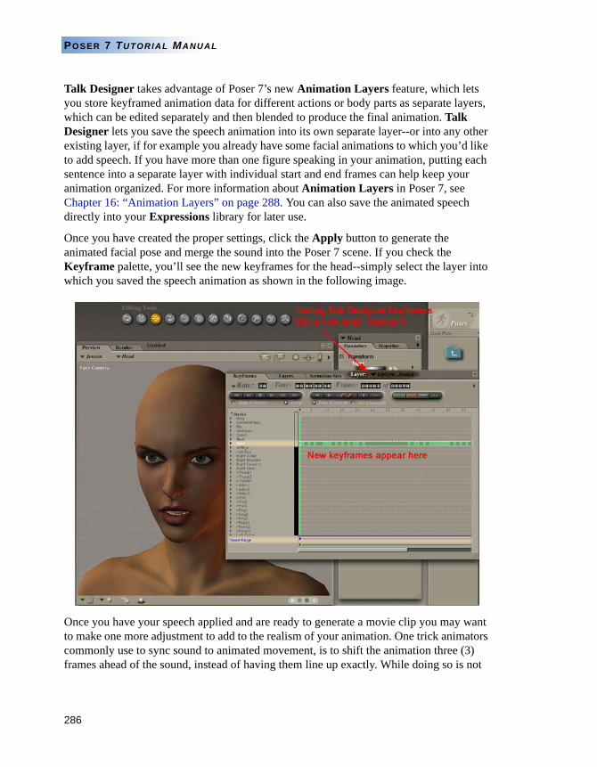
286
POSER 7 TUTORIAL MANUAL
Talk Designer takes advantage of Poser 7’s new Animation Layers feature, which lets you store keyframed animation data for different actions or body parts as separate layers, which can be edited separately and then blended to produce the final animation. Talk Designer lets you save the speech animation into its own separate layer--or into any other existing layer, if for example you already have some facial animations to which you’d like to add speech. If you have more than one figure speaking in your animation, putting each sentence into a separate layer with individual start and end frames can help keep your animation organized. For more information about Animation Layers in Poser 7, see Chapter 16: “Animation Layers” on page 288. You can also save the animated speech directly into your Expressions library for later use.
Once you have created the proper settings, click the Apply button to generate the animated facial pose and merge the sound into the Poser 7 scene. If you check the Keyframe palette, you’ll see the new keyframes for the head--simply select the layer into which you saved the speech animation as shown in the following image.
Once you have your speech applied and are ready to generate a movie clip you may want to make one more adjustment to add to the realism of your animation. One trick animators commonly use to sync sound to animated movement, is to shift the animation three (3) frames ahead of the sound, instead of having them line up exactly. While doing so is not

287
POSING AND ANIMATION
necessary, it creates subtle anticipation that adds to the level of realism. An easy way to achieve this is to locate the blue Play Range bar at the bottom of the Animation palette, click on the blue arrow at the start of the blue bar and drag it forward two or three frames. Now the sound will have a slight delay, and have a more natural look when you create your movie clip.
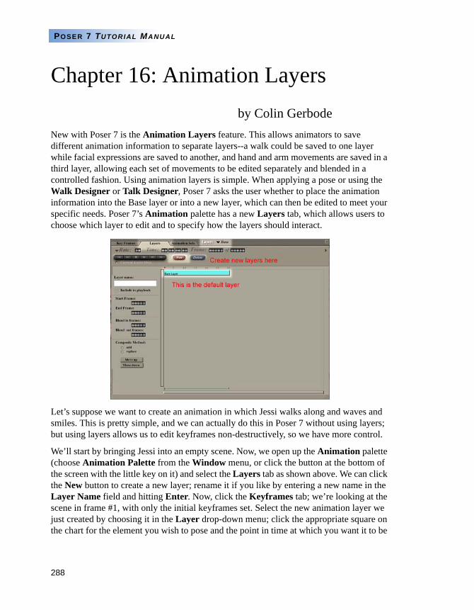
288
POSER 7 TUTORIAL MANUAL
Chapter 16: Animation Layersby Colin Gerbode
New with Poser 7 is the Animation Layers feature. This allows animators to save different animation information to separate layers--a walk could be saved to one layer while facial expressions are saved to another, and hand and arm movements are saved in a third layer, allowing each set of movements to be edited separately and blended in a controlled fashion. Using animation layers is simple. When applying a pose or using the Walk Designer or Talk Designer, Poser 7 asks the user whether to place the animation information into the Base layer or into a new layer, which can then be edited to meet your specific needs. Poser 7’s Animation palette has a new Layers tab, which allows users to choose which layer to edit and to specify how the layers should interact.
Let’s suppose we want to create an animation in which Jessi walks along and waves and smiles. This is pretty simple, and we can actually do this in Poser 7 without using layers; but using layers allows us to edit keyframes non-destructively, so we have more control.
We’ll start by bringing Jessi into an empty scene. Now, we open up the Animation palette (choose Animation Palette from the Window menu, or click the button at the bottom of the screen with the little key on it) and select the Layers tab as shown above. We can click the New button to create a new layer; rename it if you like by entering a new name in the Layer Name field and hitting Enter. Now, click the Keyframes tab; we’re looking at the scene in frame #1, with only the initial keyframes set. Select the new animation layer we just created by choosing it in the Layer drop-down menu; click the appropriate square on the chart for the element you wish to pose and the point in time at which you want it to be
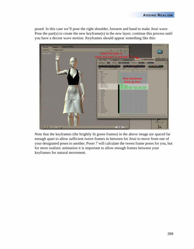
289
ADDING REALISM
posed. In this case we’ll pose the right shoulder, forearm and hand to make Jessi wave. Pose the part(s) to create the new keyframe(s) in the new layer; continue this process until you have a decent wave motion. Keyframes should appear something like this:
Note that the keyframes (the brightly lit green frames) in the above image are spaced far enough apart to allow sufficient tween frames in between for Jessi to move from one of your designated poses to another. Poser 7 will calculate the tween frame poses for you, but for more realistic animation it is important to allow enough frames between your keyframes for natural movement.
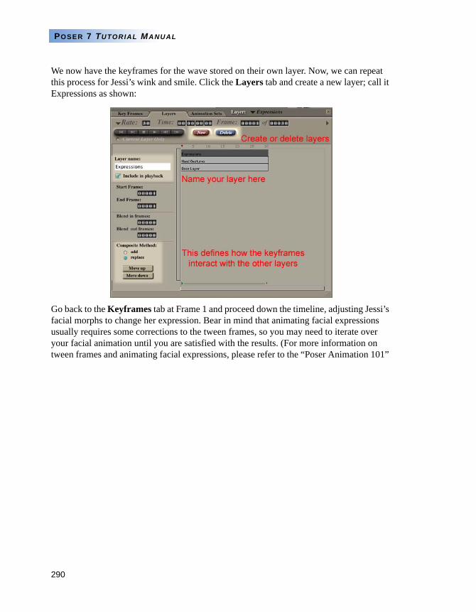
290
POSER 7 TUTORIAL MANUAL
We now have the keyframes for the wave stored on their own layer. Now, we can repeat this process for Jessi’s wink and smile. Click the Layers tab and create a new layer; call it Expressions as shown:
Go back to the Keyframes tab at Frame 1 and proceed down the timeline, adjusting Jessi’s facial morphs to change her expression. Bear in mind that animating facial expressions usually requires some corrections to the tween frames, so you may need to iterate over your facial animation until you are satisfied with the results. (For more information on tween frames and animating facial expressions, please refer to the “Poser Animation 101”
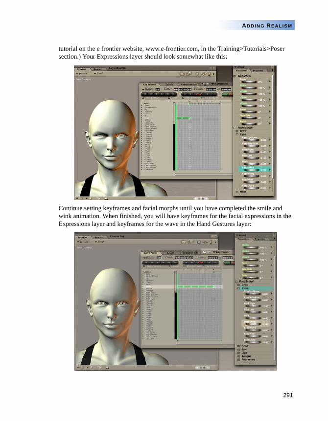
291
ADDING REALISM
tutorial on the e frontier website, www.e-frontier.com, in the Training>Tutorials>Poser section.) Your Expressions layer should look somewhat like this:
Continue setting keyframes and facial morphs until you have completed the smile and wink animation. When finished, you will have keyframes for the facial expressions in the Expressions layer and keyframes for the wave in the Hand Gestures layer:
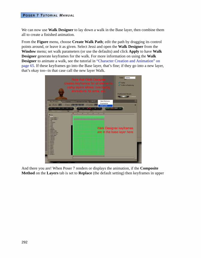
292
POSER 7 TUTORIAL MANUAL
We can now use Walk Designer to lay down a walk in the Base layer, then combine them all to create a finished animation.
From the Figure menu, choose Create Walk Path; edit the path by dragging its control points around, or leave it as given. Select Jessi and open the Walk Designer from the Window menu; set walk parameters (or use the defaults) and click Apply to have Walk Designer generate keyframes for the walk. For more information on using the Walk Designer to animate a walk, see the tutorial in “Character Creation and Animation” on page 65. If these keyframes go into the Base layer, that’s fine; if they go into a new layer, that’s okay too--in that case call the new layer Walk.
And there you are! When Poser 7 renders or displays the animation, if the Composite Method on the Layers tab is set to Replace (the default setting) then keyframes in upper
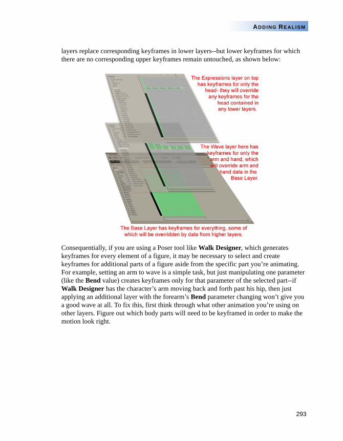
293
ADDING REALISM
layers replace corresponding keyframes in lower layers--but lower keyframes for which there are no corresponding upper keyframes remain untouched, as shown below:
Consequentially, if you are using a Poser tool like Walk Designer, which generates keyframes for every element of a figure, it may be necessary to select and create keyframes for additional parts of a figure aside from the specific part you’re animating. For example, setting an arm to wave is a simple task, but just manipulating one parameter (like the Bend value) creates keyframes only for that parameter of the selected part--if Walk Designer has the character’s arm moving back and forth past his hip, then just applying an additional layer with the forearm’s Bend parameter changing won’t give you a good wave at all. To fix this, first think through what other animation you’re using on other layers. Figure out which body parts will need to be keyframed in order to make the motion look right.
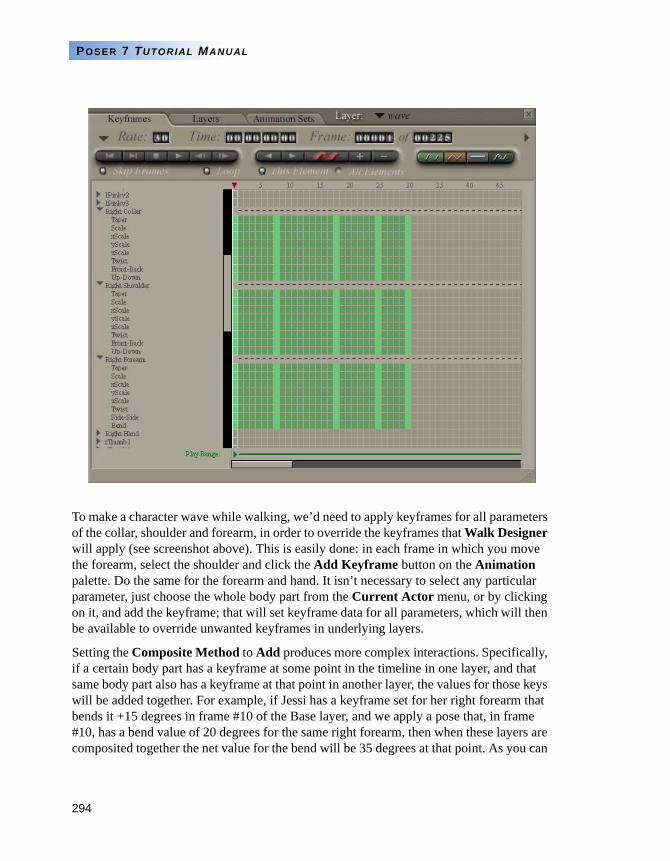
294
POSER 7 TUTORIAL MANUAL
To make a character wave while walking, we’d need to apply keyframes for all parameters of the collar, shoulder and forearm, in order to override the keyframes that Walk Designer will apply (see screenshot above). This is easily done: in each frame in which you move the forearm, select the shoulder and click the Add Keyframe button on the Animation palette. Do the same for the forearm and hand. It isn’t necessary to select any particular parameter, just choose the whole body part from the Current Actor menu, or by clicking on it, and add the keyframe; that will set keyframe data for all parameters, which will then be available to override unwanted keyframes in underlying layers.
Setting the Composite Method to Add produces more complex interactions. Specifically, if a certain body part has a keyframe at some point in the timeline in one layer, and that same body part also has a keyframe at that point in another layer, the values for those keys will be added together. For example, if Jessi has a keyframe set for her right forearm that bends it +15 degrees in frame #10 of the Base layer, and we apply a pose that, in frame #10, has a bend value of 20 degrees for the same right forearm, then when these layers are composited together the net value for the bend will be 35 degrees at that point. As you can
295
ADDING REALISM
imagine this can produce some odd effects especially when using poses in combination with Walk Designer, which provides keyframe values for everything in every frame--so we suggest that the Add method be used sparingly and with careful thought as to its effects.
Remember, when looking at the Graph palette or the Keyframes tab in the Animation palette, you'll only see values for the current layer- although in order to help visualize the net effects of changes made over the various layers, the Graph palette now has an additional display--a grey or dotted line- which shows the value of the current parameter taking into account the various layers and Composite Modes. Thus, if the dotted line is the same as the solid red one on the graph display, the Composite Method is most likely set to Replace, and any frames with data (keyframes or tween frames) will replace frames in layers below them. If the dotted line diverges from the solid red one, the Composite Method is set to Add, and underlying frame data is affecting the final result.
There are a couple of things to be aware of when using animation layers that have to do with the way in which keyframes are applied, viewed and modified as you work in the various layers. Certain animation tools display all the layers--the Document window, for example--while others show only the current layer regardless of setting, like the Parameters and Graph palettes, as well as the Keyframes tab of the Animation palette. Don't be surprised if certain keyframes that you have set seem to 'disappear' if you switch layers--this is normal, the keyframes are still there, they're just not on the current layer.
A layer begins at its start frame but may contain keyframes that exist 'after' its end frame; the end frame merely determines the point at which the frames in the layer are no longer applied or viewed; frames after the end frame are still in existence but are ignored. Moving the start frame, then, will change the position of any keyframes in the layer, while moving the end frame won't (but may reveal or obscure keyframes that have already been set.) Moving a layer forward or back along the timeline in the Layers tab of the Animation palette does reposition the keyframes in that layer along the timeline; their spacing relative to each other won't be affected. Think of each animation layer as a piece of film laid atop other pieces of film- everything on a given bit of film moves together.
Adding a keyframe to a layer in a frame that's outside the frame range of that layer will automatically extend the layer to include the new frame(s). This can change the start frame of the current layer! For example, suppose we have a layer that begins on frame 10. While working on that layer, we add a keyframe in frame 5--the layer's start frame will now be 5, although the other keyframe values in that layer will not move. If you now need to adjust your start frame for that layer, it will reposition the existing keyframes- you'll need to select them in the Keyframes tab and move them back into position by hand if necessary.
296
POSER 7 TUTORIAL MANUAL
A note about applying Library poses: The first time you change a pose in a layer, if there aren't already keyframes at the beginning and end of the layer, they will be created. Thus, your keyframed change won't just 'pop' into existence in the scene, rather the actor being posed will move into position over the timespan of the layer, and then hold its position. However, applying a pose from the library does not create these new keyframes; applying a library pose only adds the specific keyframes stored in that pose, so if your library pose isn't an animated pose then you'll want to set keyframes at the beginning and end of the layer, to avoid having the pose 'pop up' and then disappear.
297
Chapter 17: Advanced Posing and Animation
rom previous chapters within this manual, you should now have a grasp of the basic procedures involved in posing and animating figures within Poser Figure Artist. This chapter introduces several Poser Figure Artist features that will enable you to refine your techniques, to create more realistic images and animations.
AUTO BALANCE AND POSING
The Auto Balance feature can be a valuable tool for creating realistic poses. When the feature is enabled, Poser Figure Artist calculates what the mathematical “weight” for a figure is and then tries to maintain it. In this mathematical model, there is more weight in the hip or center portion of the figure, than there is in the upper torso.
As you move figures, Poser Figure Artist automatically adjusts body parts to attempt to maintain the original weight distribution. This results in more natural looking poses, without the need to make several position adjustments.
To further affect the weight distribution and compensation calculations, you can reposition the Center of Mass Control Object (red outlined ball) at the base of the figure. This control object is adjustable along the X and Z axes in the ground plane. Moving the Center of Mass Control Object also adjusts the Center of Mass Indicator, which appears as a shaded sphere in the XZ (ground) plane under the figure. This Indicator
F
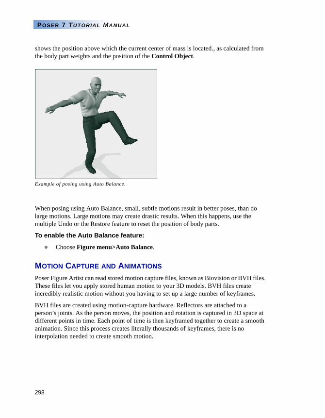
298
POSER 7 TUTORIAL MANUAL
shows the position above which the current center of mass is located., as calculated from the body part weights and the position of the Control Object.
When posing using Auto Balance, small, subtle motions result in better poses, than do large motions. Large motions may create drastic results. When this happens, use the multiple Undo or the Restore feature to reset the position of body parts.
To enable the Auto Balance feature:
Choose Figure menu>Auto Balance.
MOTION CAPTURE AND ANIMATIONS
Poser Figure Artist can read stored motion capture files, known as Biovision or BVH files. These files let you apply stored human motion to your 3D models. BVH files create incredibly realistic motion without you having to set up a large number of keyframes.
BVH files are created using motion-capture hardware. Reflectors are attached to a person’s joints. As the person moves, the position and rotation is captured in 3D space at different points in time. Each point of time is then keyframed together to create a smooth animation. Since this process creates literally thousands of keyframes, there is no interpolation needed to create smooth motion.
Example of posing using Auto Balance.
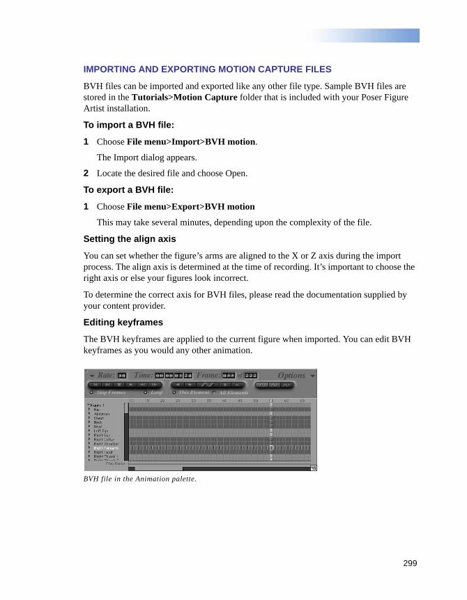
299
IMPORTING AND EXPORTING MOTION CAPTURE FILES
BVH files can be imported and exported like any other file type. Sample BVH files are stored in the Tutorials>Motion Capture folder that is included with your Poser Figure Artist installation.
To import a BVH file:
1 Choose File menu>Import>BVH motion.
The Import dialog appears.
2 Locate the desired file and choose Open.
To export a BVH file:
1 Choose File menu>Export>BVH motion
This may take several minutes, depending upon the complexity of the file.
Setting the align axis
You can set whether the figure’s arms are aligned to the X or Z axis during the import process. The align axis is determined at the time of recording. It’s important to choose the right axis or else your figures look incorrect.
To determine the correct axis for BVH files, please read the documentation supplied by your content provider.
Editing keyframes
The BVH keyframes are applied to the current figure when imported. You can edit BVH keyframes as you would any other animation.
BVH file in the Animation palette.
PART 5
Figure Shapingand Creation
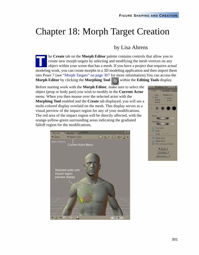
301
FIGURE SHAPING AND CREATION
Chapter 18: Morph Target Creationby Lisa Ahrens
he Create tab on the Morph Editor palette contains controls that allow you to create new morph targets by selecting and modifying the mesh vertices on any object within your scene that has a mesh. If you have a project that requires actual
modeling work, you can create morphs in a 3D modeling application and then import them into Poser 7 (see “Morph Targets” on page 307 for more information).You can access the Morph Editor by clicking the Morphing Tool within the Editing Tools display.
Before starting work with the Morph Editor, make sure to select the object (prop or body part) you wish to modify in the Current Actor menu. When you then mouse over the selected actor with the Morphing Tool enabled and the Create tab displayed, you will see a multi-colored display overlaid on the mesh. This display serves as a visual preview of the impact region for any of your modifications. The red area of the impact region will be directly affected, with the orange-yellow-green surrounding areas indicating the gradiated falloff region for the modifications.
T
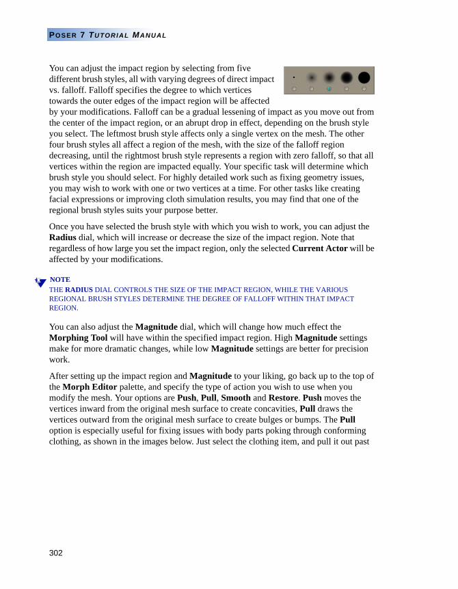
302
POSER 7 TUTORIAL MANUAL
You can adjust the impact region by selecting from five different brush styles, all with varying degrees of direct impact vs. falloff. Falloff specifies the degree to which vertices towards the outer edges of the impact region will be affected by your modifications. Falloff can be a gradual lessening of impact as you move out from the center of the impact region, or an abrupt drop in effect, depending on the brush style you select. The leftmost brush style affects only a single vertex on the mesh. The other four brush styles all affect a region of the mesh, with the size of the falloff region decreasing, until the rightmost brush style represents a region with zero falloff, so that all vertices within the region are impacted equally. Your specific task will determine which brush style you should select. For highly detailed work such as fixing geometry issues, you may wish to work with one or two vertices at a time. For other tasks like creating facial expressions or improving cloth simulation results, you may find that one of the regional brush styles suits your purpose better.
Once you have selected the brush style with which you wish to work, you can adjust the Radius dial, which will increase or decrease the size of the impact region. Note that regardless of how large you set the impact region, only the selected Current Actor will be affected by your modifications.
NOTETHE RADIUS DIAL CONTROLS THE SIZE OF THE IMPACT REGION, WHILE THE VARIOUS REGIONAL BRUSH STYLES DETERMINE THE DEGREE OF FALLOFF WITHIN THAT IMPACT REGION.
You can also adjust the Magnitude dial, which will change how much effect the Morphing Tool will have within the specified impact region. High Magnitude settings make for more dramatic changes, while low Magnitude settings are better for precision work.
After setting up the impact region and Magnitude to your liking, go back up to the top of the Morph Editor palette, and specify the type of action you wish to use when you modify the mesh. Your options are Push, Pull, Smooth and Restore. Push moves the vertices inward from the original mesh surface to create concavities, Pull draws the vertices outward from the original mesh surface to create bulges or bumps. The Pull option is especially useful for fixing issues with body parts poking through conforming clothing, as shown in the images below. Just select the clothing item, and pull it out past
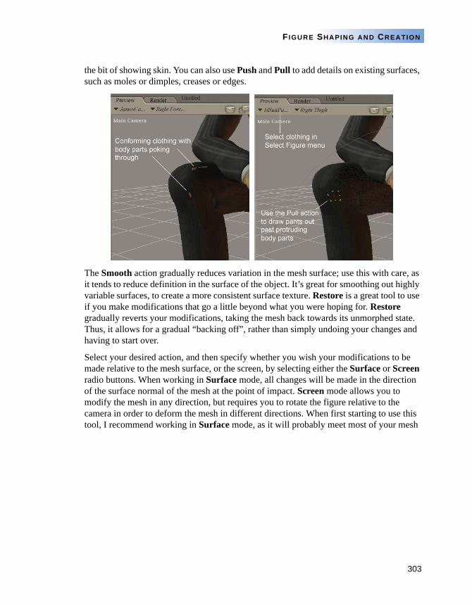
303
FIGURE SHAPING AND CREATION
the bit of showing skin. You can also use Push and Pull to add details on existing surfaces, such as moles or dimples, creases or edges.
The Smooth action gradually reduces variation in the mesh surface; use this with care, as it tends to reduce definition in the surface of the object. It’s great for smoothing out highly variable surfaces, to create a more consistent surface texture. Restore is a great tool to use if you make modifications that go a little beyond what you were hoping for. Restore gradually reverts your modifications, taking the mesh back towards its unmorphed state. Thus, it allows for a gradual “backing off”, rather than simply undoing your changes and having to start over.
Select your desired action, and then specify whether you wish your modifications to be made relative to the mesh surface, or the screen, by selecting either the Surface or Screen radio buttons. When working in Surface mode, all changes will be made in the direction of the surface normal of the mesh at the point of impact. Screen mode allows you to modify the mesh in any direction, but requires you to rotate the figure relative to the camera in order to deform the mesh in different directions. When first starting to use this tool, I recommend working in Surface mode, as it will probably meet most of your mesh
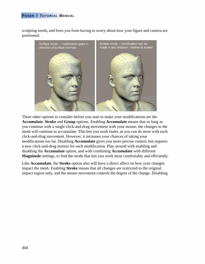
304
POSER 7 TUTORIAL MANUAL
sculpting needs, and frees you from having to worry about how your figure and camera are positioned.
Three other options to consider before you start to make your modifications are the Accumulate, Stroke and Group options. Enabling Accumulate means that so long as you continue with a single click-and-drag movement with your mouse, the changes to the mesh will continue to accumulate. This lets you work faster, as you can do more with each click-and-drag movement. However, it increases your chances of taking your modifications too far. Disabling Accumulate gives you more precise control, but requires a new click-and-drag motion for each modification. Play around with enabling and disabling the Accumulate option, and with combining Accumulate with different Magnitude settings, to find the mode that lets you work most comfortably and efficiently.
Like Accumulate, the Stroke option also will have a direct affect on how your changes impact the mesh. Enabling Stroke means that all changes are restricted to the original impact region only, and the mouse movement controls the degree of the change. Disabling
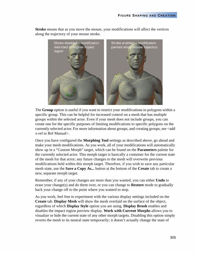
305
FIGURE SHAPING AND CREATION
Stroke means that as you move the mouse, your modifications will affect the vertices along the trajectory of your mouse stroke.
The Group option is useful if you want to restrict your modifications to polygons within a specific group. This can be helpful for increased control on a mesh that has multiple groups within the selected actor. Even if your mesh does not include groups, you can create one for the specific purposes of limiting modifications to specific polygons on the currently selected actor. For more information about groups, and creating groups, see <add x-ref to Ref Manual>.
Once you have configured the Morphing Tool settings as described above, go ahead and make your mesh modifications. As you work, all of your modifications will automatically show up in a “Custom Morph” target, which can be found on the Parameters palette for the currently selected actor. This morph target is basically a container for the current state of the mesh for that actor; any future changes to the mesh will overwrite previous modifications held within this morph target. Therefore, if you wish to save any particular mesh state, use the Save a Copy As... button at the bottom of the Create tab to create a new, separate morph target.
Remember, if any of your changes are more than you wanted, you can either Undo to erase your change(s) and do them over, or you can change to Restore mode to gradually back your change off to the point where you wanted to stop.
As you work, feel free to experiment with the various display settings included on the Create tab. Display Mesh will show the mesh overlaid on the surface of the object, regardless of which Display Style option you are using. Display Brush enables and disables the impact region preview display. Work with Current Morphs allows you to visualize or hide the current state of any other morph targets. Disabling this option simply reverts the mesh to its neutral state temporarily; it doesn’t actually change the state of
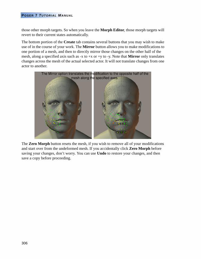
306
POSER 7 TUTORIAL MANUAL
those other morph targets. So when you leave the Morph Editor, those morph targets will revert to their current states automatically.
The bottom portion of the Create tab contains several buttons that you may wish to make use of in the course of your work. The Mirror button allows you to make modifications to one portion of a mesh, and then to directly mirror those changes on the other half of the mesh, along a specified axis such as -x to +x or +y to -y. Note that Mirror only translates changes across the mesh of the actual selected actor. It will not translate changes from one actor to another.
The Zero Morph button resets the mesh, if you wish to remove all of your modifications and start over from the undeformed mesh. If you accidentally click Zero Morph before saving your changes, don’t worry. You can use Undo to restore your changes, and then save a copy before proceeding.
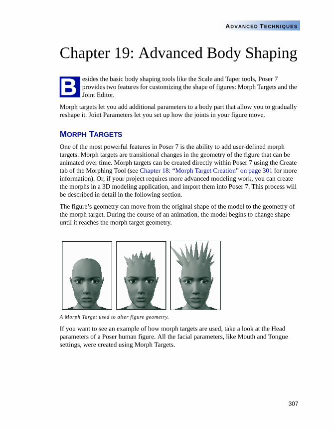
307
ADVANCED TECHNIQUES
Chapter 19: Advanced Body Shapingesides the basic body shaping tools like the Scale and Taper tools, Poser 7 provides two features for customizing the shape of figures: Morph Targets and the Joint Editor.
Morph targets let you add additional parameters to a body part that allow you to gradually reshape it. Joint Parameters let you set up how the joints in your figure move.
MORPH TARGETS
One of the most powerful features in Poser 7 is the ability to add user-defined morph targets. Morph targets are transitional changes in the geometry of the figure that can be animated over time. Morph targets can be created directly within Poser 7 using the Create tab of the Morphing Tool (see Chapter 18: “Morph Target Creation” on page 301 for more information). Or, if your project requires more advanced modeling work, you can create the morphs in a 3D modeling application, and import them into Poser 7. This process will be described in detail in the following section.
The figure’s geometry can move from the original shape of the model to the geometry of the morph target. During the course of an animation, the model begins to change shape until it reaches the morph target geometry.
If you want to see an example of how morph targets are used, take a look at the Head parameters of a Poser human figure. All the facial parameters, like Mouth and Tongue settings, were created using Morph Targets.
A Morph Target used to alter figure geometry.
B
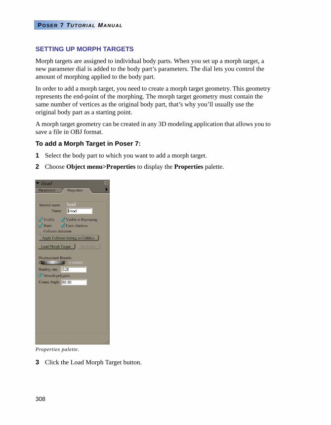
308
POSER 7 TUTORIAL MANUAL
SETTING UP MORPH TARGETS
Morph targets are assigned to individual body parts. When you set up a morph target, a new parameter dial is added to the body part’s parameters. The dial lets you control the amount of morphing applied to the body part.
In order to add a morph target, you need to create a morph target geometry. This geometry represents the end-point of the morphing. The morph target geometry must contain the same number of vertices as the original body part, that’s why you’ll usually use the original body part as a starting point.
A morph target geometry can be created in any 3D modeling application that allows you to save a file in OBJ format.
To add a Morph Target in Poser 7:
1 Select the body part to which you want to add a morph target.
2 Choose Object menu>Properties to display the Properties palette.
3 Click the Load Morph Target button.
Properties palette.
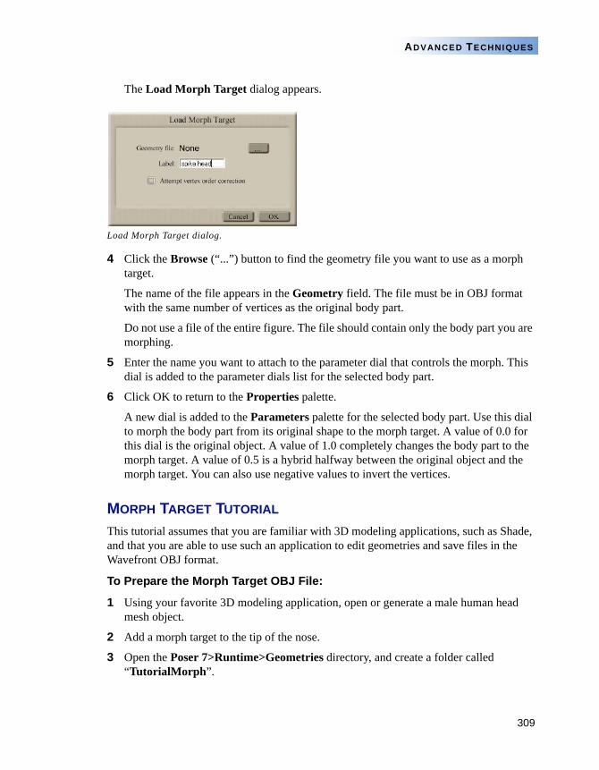
309
ADVANCED TECHNIQUES
The Load Morph Target dialog appears.
4 Click the Browse (“...”) button to find the geometry file you want to use as a morph target.
The name of the file appears in the Geometry field. The file must be in OBJ format with the same number of vertices as the original body part.
Do not use a file of the entire figure. The file should contain only the body part you are morphing.
5 Enter the name you want to attach to the parameter dial that controls the morph. This dial is added to the parameter dials list for the selected body part.
6 Click OK to return to the Properties palette.
A new dial is added to the Parameters palette for the selected body part. Use this dial to morph the body part from its original shape to the morph target. A value of 0.0 for this dial is the original object. A value of 1.0 completely changes the body part to the morph target. A value of 0.5 is a hybrid halfway between the original object and the morph target. You can also use negative values to invert the vertices.
MORPH TARGET TUTORIAL
This tutorial assumes that you are familiar with 3D modeling applications, such as Shade, and that you are able to use such an application to edit geometries and save files in the Wavefront OBJ format.
To Prepare the Morph Target OBJ File:
1 Using your favorite 3D modeling application, open or generate a male human head mesh object.
2 Add a morph target to the tip of the nose.
3 Open the Poser 7>Runtime>Geometries directory, and create a folder called “TutorialMorph”.
Load Morph Target dialog.
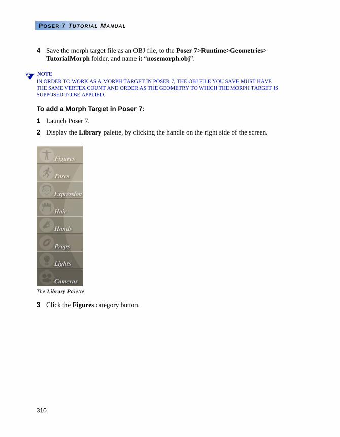
310
POSER 7 TUTORIAL MANUAL
4 Save the morph target file as an OBJ file, to the Poser 7>Runtime>Geometries> TutorialMorph folder, and name it “nosemorph.obj”.
NOTEIN ORDER TO WORK AS A MORPH TARGET IN POSER 7, THE OBJ FILE YOU SAVE MUST HAVE THE SAME VERTEX COUNT AND ORDER AS THE GEOMETRY TO WHICH THE MORPH TARGET IS SUPPOSED TO BE APPLIED.
To add a Morph Target in Poser 7:
1 Launch Poser 7.
2 Display the Library palette, by clicking the handle on the right side of the screen.
3 Click the Figures category button.
The Library Palette.
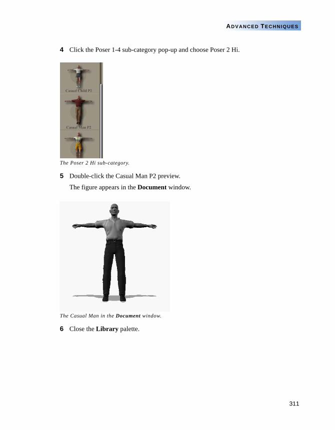
311
ADVANCED TECHNIQUES
4 Click the Poser 1-4 sub-category pop-up and choose Poser 2 Hi.
5 Double-click the Casual Man P2 preview.
The figure appears in the Document window.
6 Close the Library palette.
The Poser 2 Hi sub-category.
The Casual Man in the Document window.
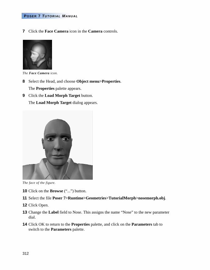
312
POSER 7 TUTORIAL MANUAL
7 Click the Face Camera icon in the Camera controls.
8 Select the Head, and choose Object menu>Properties.
The Properties palette appears.
9 Click the Load Morph Target button.
The Load Morph Target dialog appears.
10 Click on the Browse (“...”) button.
11 Select the file Poser 7>Runtime>Geometries>TutorialMorph>nosemorph.obj.
12 Click Open.
13 Change the Label field to Nose. This assigns the name “Nose” to the new parameter dial.
14 Click OK to return to the Properties palette, and click on the Parameters tab to switch to the Parameters palette.
The Face Camera icon.
The face of the figure.
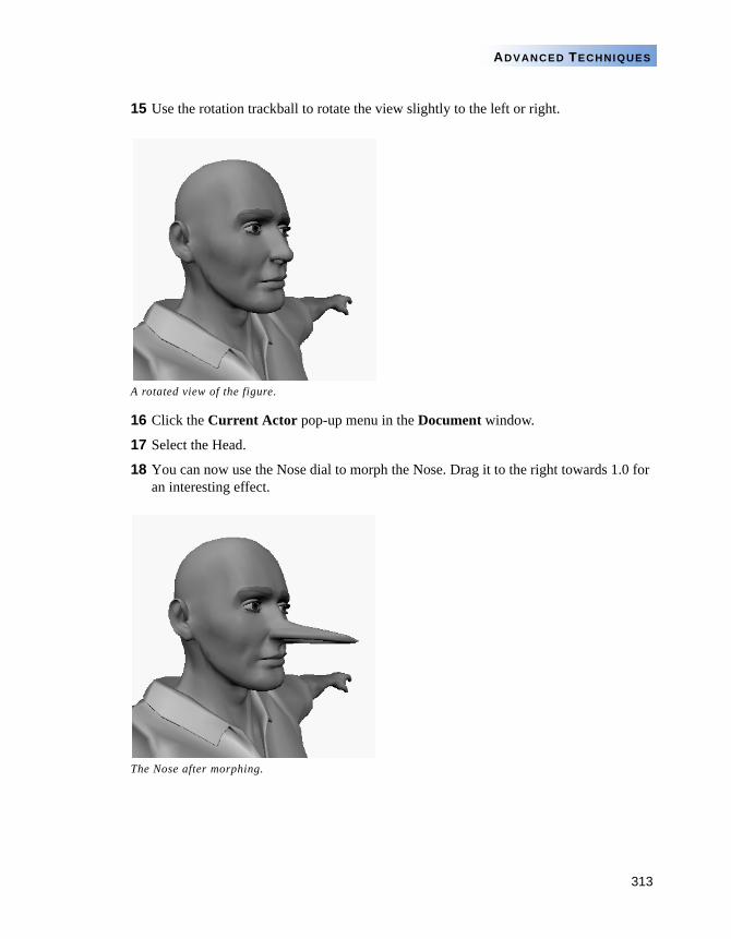
313
ADVANCED TECHNIQUES
15 Use the rotation trackball to rotate the view slightly to the left or right.
16 Click the Current Actor pop-up menu in the Document window.
17 Select the Head.
18 You can now use the Nose dial to morph the Nose. Drag it to the right towards 1.0 for an interesting effect.
A rotated view of the figure.
The Nose after morphing.
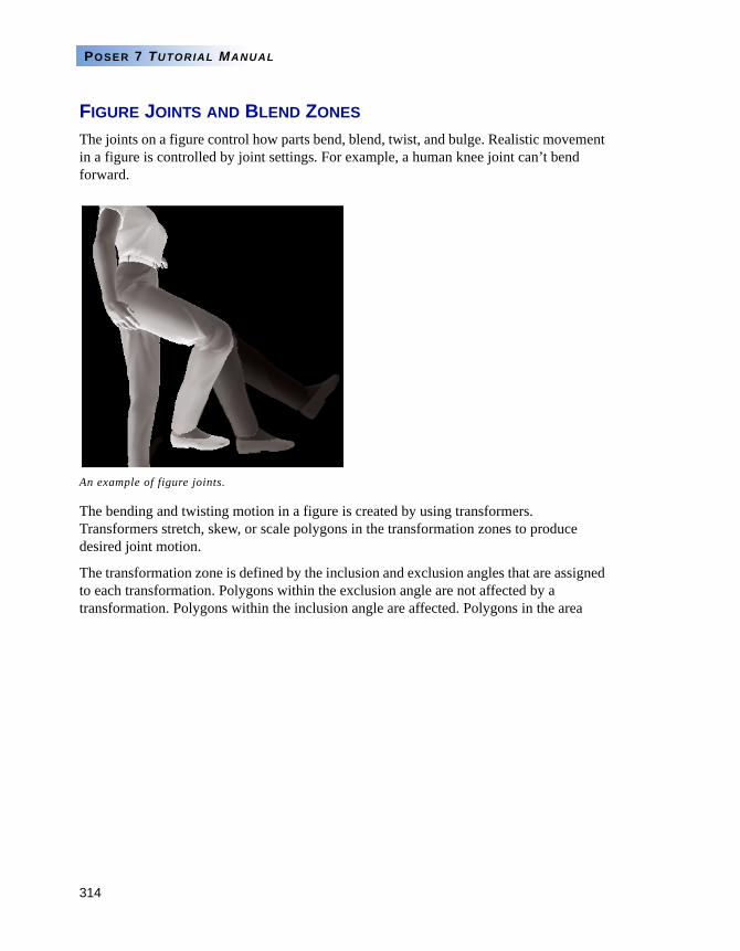
314
POSER 7 TUTORIAL MANUAL
FIGURE JOINTS AND BLEND ZONES
The joints on a figure control how parts bend, blend, twist, and bulge. Realistic movement in a figure is controlled by joint settings. For example, a human knee joint can’t bend forward.
The bending and twisting motion in a figure is created by using transformers. Transformers stretch, skew, or scale polygons in the transformation zones to produce desired joint motion.
The transformation zone is defined by the inclusion and exclusion angles that are assigned to each transformation. Polygons within the exclusion angle are not affected by a transformation. Polygons within the inclusion angle are affected. Polygons in the area
An example of figure joints.
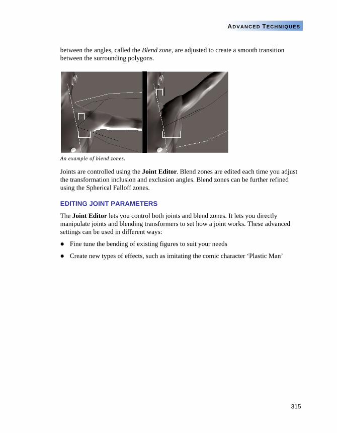
315
ADVANCED TECHNIQUES
between the angles, called the Blend zone, are adjusted to create a smooth transition between the surrounding polygons.
Joints are controlled using the Joint Editor. Blend zones are edited each time you adjust the transformation inclusion and exclusion angles. Blend zones can be further refined using the Spherical Falloff zones.
EDITING JOINT PARAMETERS
The Joint Editor lets you control both joints and blend zones. It lets you directly manipulate joints and blending transformers to set how a joint works. These advanced settings can be used in different ways:
Fine tune the bending of existing figures to suit your needs
Create new types of effects, such as imitating the comic character ‘Plastic Man’
An example of blend zones.
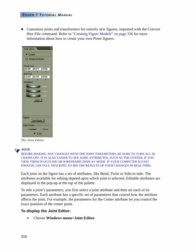
316
POSER 7 TUTORIAL MANUAL
Customize joints and transformers for entirely new figures, imported with the Convert Hier File command. Refer to “Creating Figure Models” on page 336 for more information about how to create your own Poser figures.
NOTEBEFORE MAKING ANY CHANGES WITH THE JOINT PARAMETERS, BE SURE TO TURN ALL IK CHAINS OFF. IT IS ALSO EASIER TO SEE SOME ATTRIBUTES, SUCH AS THE CENTER, IF YOU VIEW THEM IN OUTLINE OR WIREFRAME DISPLAY MODE. IF YOUR COMPUTER IS FAST ENOUGH, USE FULL TRACKING TO SEE THE RESULTS OF YOUR CHANGES IN REAL-TIME.
Each joint on the figure has a set of attributes, like Bend, Twist or Side-to-side. The attributes available for editing depend upon which joint is selected. Editable attributes are displayed in the pop-up at the top of the palette.
To edit a joint’s parameters, you first select a joint attribute and then set each of its parameters. Each attribute has a specific set of parameters that control how the attribute affects the joint. For example, the parameters for the Center attribute let you control the exact position of the center point.
To display the Joint Editor:
Choose Windows menu>Joint Editor.
The Joint Editor.
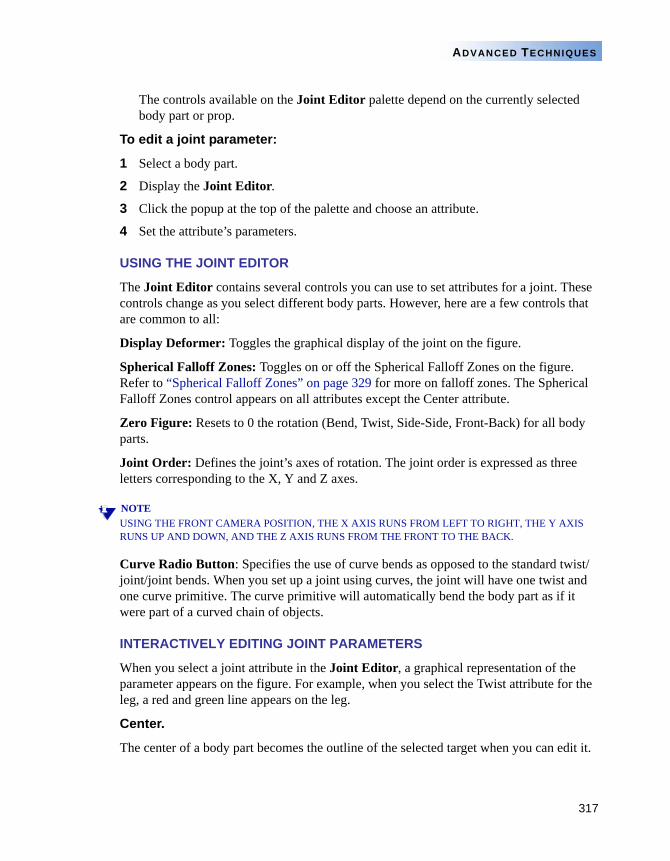
317
ADVANCED TECHNIQUES
The controls available on the Joint Editor palette depend on the currently selected body part or prop.
To edit a joint parameter:
1 Select a body part.
2 Display the Joint Editor.
3 Click the popup at the top of the palette and choose an attribute.
4 Set the attribute’s parameters.
USING THE JOINT EDITOR
The Joint Editor contains several controls you can use to set attributes for a joint. These controls change as you select different body parts. However, here are a few controls that are common to all:
Display Deformer: Toggles the graphical display of the joint on the figure.
Spherical Falloff Zones: Toggles on or off the Spherical Falloff Zones on the figure. Refer to “Spherical Falloff Zones” on page 329 for more on falloff zones. The Spherical Falloff Zones control appears on all attributes except the Center attribute.
Zero Figure: Resets to 0 the rotation (Bend, Twist, Side-Side, Front-Back) for all body parts.
Joint Order: Defines the joint’s axes of rotation. The joint order is expressed as three letters corresponding to the X, Y and Z axes.
NOTEUSING THE FRONT CAMERA POSITION, THE X AXIS RUNS FROM LEFT TO RIGHT, THE Y AXIS RUNS UP AND DOWN, AND THE Z AXIS RUNS FROM THE FRONT TO THE BACK.
Curve Radio Button: Specifies the use of curve bends as opposed to the standard twist/joint/joint bends. When you set up a joint using curves, the joint will have one twist and one curve primitive. The curve primitive will automatically bend the body part as if it were part of a curved chain of objects.
INTERACTIVELY EDITING JOINT PARAMETERS
When you select a joint attribute in the Joint Editor, a graphical representation of the parameter appears on the figure. For example, when you select the Twist attribute for the leg, a red and green line appears on the leg.
Center.
The center of a body part becomes the outline of the selected target when you can edit it.
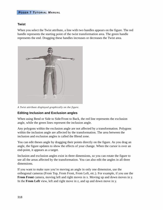
318
POSER 7 TUTORIAL MANUAL
Twist
When you select the Twist attribute, a line with two handles appears on the figure. The red handle represents the starting point of the twist transformation area. The green handle represents the end. Dragging these handles increases or decreases the Twist area.
Editing Inclusion and Exclusion angles
When using Bend or Side to Side/Front to Back, the red line represents the exclusion angle, while the green lines represent the inclusion angle.
Any polygons within the exclusion angle are not affected by a transformation. Polygons within the inclusion angle are affected by the transformation. The area between the inclusion and exclusion angles is called the Blend zone.
You can edit theses angle by dragging their points directly on the figure. As you drag an angle, the figure updates to show the effects of your change. When the cursor is over an end-point, it appears as a target.
Inclusion and exclusion angles exist in three dimensions, so you can rotate the figure to see all the areas affected by the transformation. You can also edit the angles in all three dimensions.
If you want to make sure you’re moving an angle in only one dimension, use the orthogonal cameras (From Top, From Front, From Left, etc.). For example, if you use the From Front camera, moving left and right moves in x. Moving up and down moves in y. In the From Left view, left and right move in z, and up and down move in y.
A Twist attribute displayed graphically on the figure.
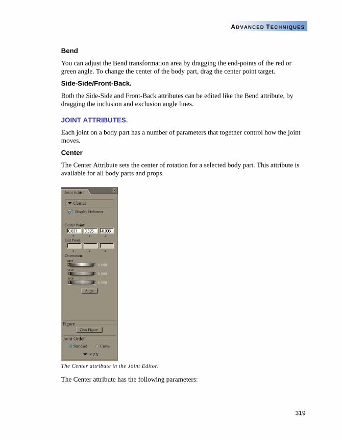
319
ADVANCED TECHNIQUES
Bend
You can adjust the Bend transformation area by dragging the end-points of the red or green angle. To change the center of the body part, drag the center point target.
Side-Side/Front-Back.
Both the Side-Side and Front-Back attributes can be edited like the Bend attribute, by dragging the inclusion and exclusion angle lines.
JOINT ATTRIBUTES.
Each joint on a body part has a number of parameters that together control how the joint moves.
Center
The Center Attribute sets the center of rotation for a selected body part. This attribute is available for all body parts and props.
The Center attribute has the following parameters:
The Center attribute in the Joint Editor.
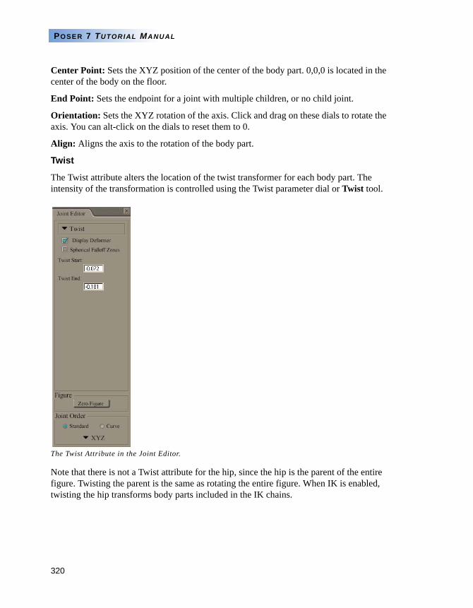
320
POSER 7 TUTORIAL MANUAL
Center Point: Sets the XYZ position of the center of the body part. 0,0,0 is located in the center of the body on the floor.
End Point: Sets the endpoint for a joint with multiple children, or no child joint.
Orientation: Sets the XYZ rotation of the axis. Click and drag on these dials to rotate the axis. You can alt-click on the dials to reset them to 0.
Align: Aligns the axis to the rotation of the body part.
Twist
The Twist attribute alters the location of the twist transformer for each body part. The intensity of the transformation is controlled using the Twist parameter dial or Twist tool.
Note that there is not a Twist attribute for the hip, since the hip is the parent of the entire figure. Twisting the parent is the same as rotating the entire figure. When IK is enabled, twisting the hip transforms body parts included in the IK chains.
The Twist Attribute in the Joint Editor.
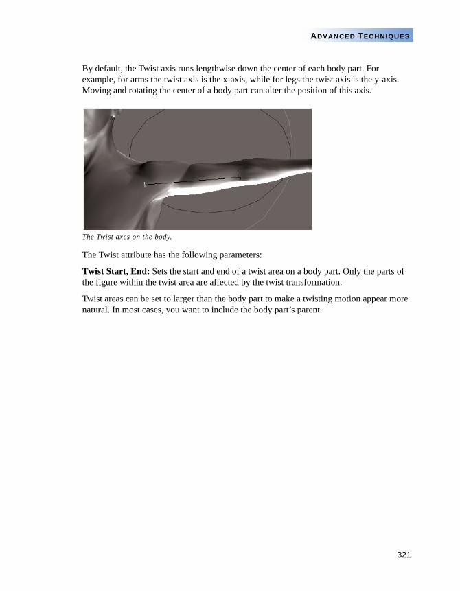
321
ADVANCED TECHNIQUES
By default, the Twist axis runs lengthwise down the center of each body part. For example, for arms the twist axis is the x-axis, while for legs the twist axis is the y-axis. Moving and rotating the center of a body part can alter the position of this axis.
The Twist attribute has the following parameters:
Twist Start, End: Sets the start and end of a twist area on a body part. Only the parts of the figure within the twist area are affected by the twist transformation.
Twist areas can be set to larger than the body part to make a twisting motion appear more natural. In most cases, you want to include the body part’s parent.
The Twist axes on the body.
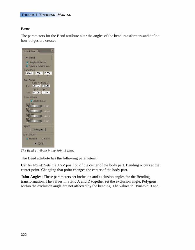
322
POSER 7 TUTORIAL MANUAL
Bend
The parameters for the Bend attribute alter the angles of the bend transformers and define how bulges are created.
The Bend attribute has the following parameters:
Center Point: Sets the XYZ position of the center of the body part. Bending occurs at the center point. Changing that point changes the center of the body part.
Joint Angles: These parameters set inclusion and exclusion angles for the Bending transformation. The values in Static A and D together set the exclusion angle. Polygons within the exclusion angle are not affected by the bending. The values in Dynamic B and
The Bend attribute in the Joint Editor.
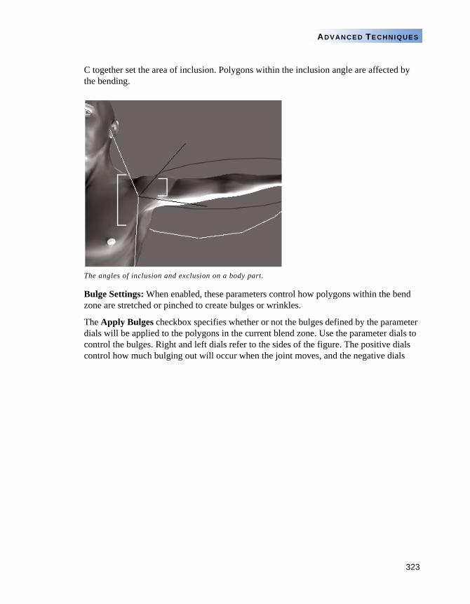
323
ADVANCED TECHNIQUES
C together set the area of inclusion. Polygons within the inclusion angle are affected by the bending.
Bulge Settings: When enabled, these parameters control how polygons within the bend zone are stretched or pinched to create bulges or wrinkles.
The Apply Bulges checkbox specifies whether or not the bulges defined by the parameter dials will be applied to the polygons in the current blend zone. Use the parameter dials to control the bulges. Right and left dials refer to the sides of the figure. The positive dials control how much bulging out will occur when the joint moves, and the negative dials
The angles of inclusion and exclusion on a body part.

324
POSER 7 TUTORIAL MANUAL
control the amount of wrinkling and pinching. You can alt-click these dials to reset them to 0.
Differences in bulges and wrinkles, when the body part center is changed.
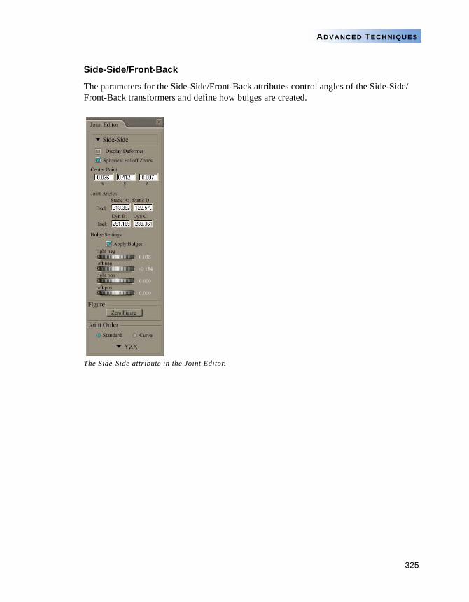
325
ADVANCED TECHNIQUES
Side-Side/Front-Back
The parameters for the Side-Side/Front-Back attributes control angles of the Side-Side/Front-Back transformers and define how bulges are created.
The Side-Side attribute in the Joint Editor.
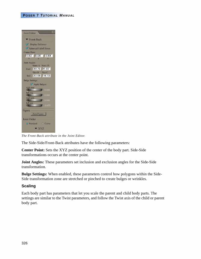
326
POSER 7 TUTORIAL MANUAL
The Side-Side/Front-Back attributes have the following parameters:
Center Point: Sets the XYZ position of the center of the body part. Side-Side transformations occurs at the center point.
Joint Angles: These parameters set inclusion and exclusion angles for the Side-Side transformation.
Bulge Settings: When enabled, these parameters control how polygons within the Side-Side transformation zone are stretched or pinched to create bulges or wrinkles.
Scaling
Each body part has parameters that let you scale the parent and child body parts. The settings are similar to the Twist parameters, and follow the Twist axis of the child or parent body part.
The Front-Back attribute in the Joint Editor.
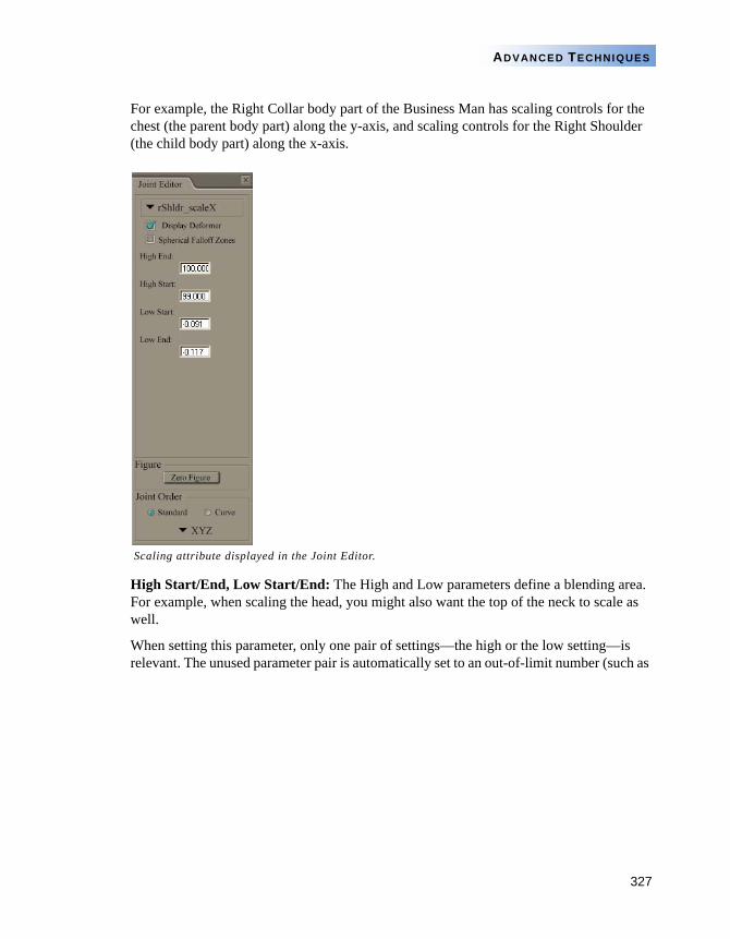
327
ADVANCED TECHNIQUES
For example, the Right Collar body part of the Business Man has scaling controls for the chest (the parent body part) along the y-axis, and scaling controls for the Right Shoulder (the child body part) along the x-axis.
High Start/End, Low Start/End: The High and Low parameters define a blending area. For example, when scaling the head, you might also want the top of the neck to scale as well.
When setting this parameter, only one pair of settings—the high or the low setting—is relevant. The unused parameter pair is automatically set to an out-of-limit number (such as
Scaling attribute displayed in the Joint Editor.
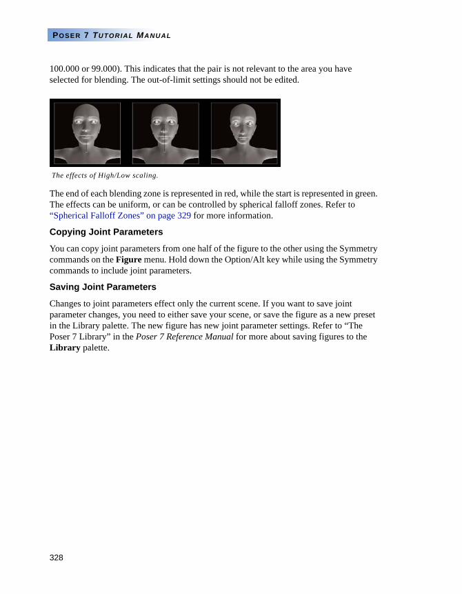
328
POSER 7 TUTORIAL MANUAL
100.000 or 99.000). This indicates that the pair is not relevant to the area you have selected for blending. The out-of-limit settings should not be edited.
The end of each blending zone is represented in red, while the start is represented in green. The effects can be uniform, or can be controlled by spherical falloff zones. Refer to “Spherical Falloff Zones” on page 329 for more information.
Copying Joint Parameters
You can copy joint parameters from one half of the figure to the other using the Symmetry commands on the Figure menu. Hold down the Option/Alt key while using the Symmetry commands to include joint parameters.
Saving Joint Parameters
Changes to joint parameters effect only the current scene. If you want to save joint parameter changes, you need to either save your scene, or save the figure as a new preset in the Library palette. The new figure has new joint parameter settings. Refer to “The Poser 7 Library” in the Poser 7 Reference Manual for more about saving figures to the Library palette.
The effects of High/Low scaling.
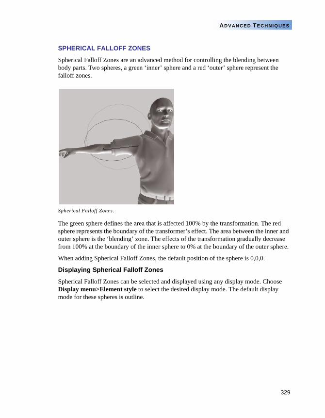
329
ADVANCED TECHNIQUES
SPHERICAL FALLOFF ZONES
Spherical Falloff Zones are an advanced method for controlling the blending between body parts. Two spheres, a green ‘inner’ sphere and a red ‘outer’ sphere represent the falloff zones.
The green sphere defines the area that is affected 100% by the transformation. The red sphere represents the boundary of the transformer’s effect. The area between the inner and outer sphere is the ‘blending’ zone. The effects of the transformation gradually decrease from 100% at the boundary of the inner sphere to 0% at the boundary of the outer sphere.
When adding Spherical Falloff Zones, the default position of the sphere is 0,0,0.
Displaying Spherical Falloff Zones
Spherical Falloff Zones can be selected and displayed using any display mode. Choose Display menu>Element style to select the desired display mode. The default display mode for these spheres is outline.
Spherical Falloff Zones.
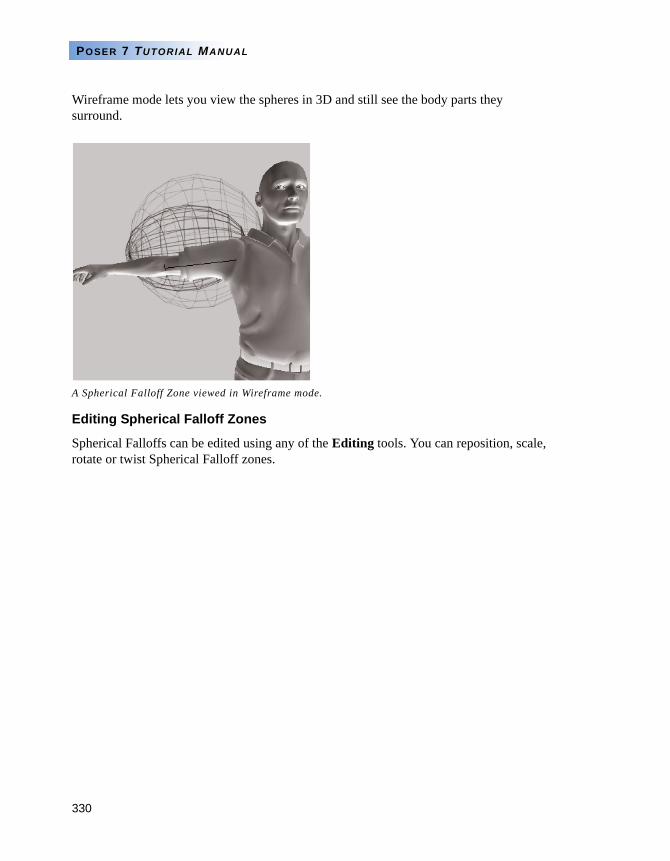
330
POSER 7 TUTORIAL MANUAL
Wireframe mode lets you view the spheres in 3D and still see the body parts they surround.
Editing Spherical Falloff Zones
Spherical Falloffs can be edited using any of the Editing tools. You can reposition, scale, rotate or twist Spherical Falloff zones.
A Spherical Falloff Zone viewed in Wireframe mode.
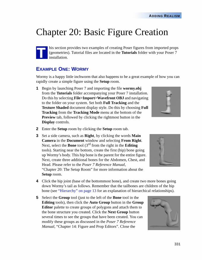
331
ADDING REALISM
Chapter 20: Basic Figure Creationhis section provides two examples of creating Poser figures from imported props (geometries). Tutorial files are located in the Tutorials folder with your Poser 7 installation.
EXAMPLE ONE: WORMY
Wormy is a happy little inchworm that also happens to be a great example of how you can rapidly create a simple figure using the Setup room.
1 Begin by launching Poser 7 and importing the file wormy.obj from the Tutorials folder accompanying your Poser 7 installation. Do this by selecting File>Import>Wavefront OBJ and navigating to the folder on your system. Set both Full Tracking and the Texture Shaded document display style. Do this by choosing Full Tracking from the Tracking Mode menu at the bottom of the Preview tab, followed by clicking the rightmost button in the Display controls.
2 Enter the Setup room by clicking the Setup room tab.
3 Set a side camera, such as Right, by clicking the words Main Camera in the Document window and selecting From Right. Next, select the Bone tool (3rd from the right in the Editing tools). Starting near the bottom, create the first (hip) bone going up Wormy’s body. This hip bone is the parent for the entire figure. Next, create three additional bones for the Abdomen, Chest, and Head. Please refer to the Poser 7 Reference Manual, “Chapter 20: The Setup Room” for more information about the Setup room.
4 Click the hip joint (base of the bottommost bone), and create two more bones going down Wormy’s tail as follows. Remember that the tailbones are children of the hip bone (see “Hierarchy” on page 13 for an explanation of hierarchical relationships).
5 Select the Group tool (just to the left of the Bone tool in the Editing tools), then click the Auto Group button in the Group Editor palette to create groups of polygons and attach them to the bone structure you created. Click the Next Group button several times to see the groups that have been created. You can modify these groups as discussed in the Poser 7 Reference Manual, “Chapter 14: Figure and Prop Editors”. Close the
T
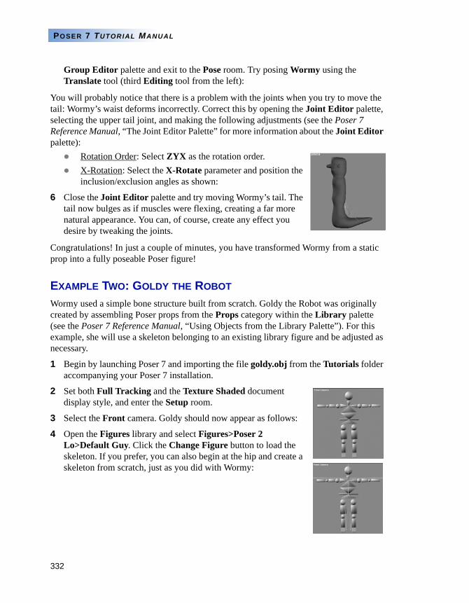
332
POSER 7 TUTORIAL MANUAL
Group Editor palette and exit to the Pose room. Try posing Wormy using the Translate tool (third Editing tool from the left):
You will probably notice that there is a problem with the joints when you try to move the tail: Wormy’s waist deforms incorrectly. Correct this by opening the Joint Editor palette, selecting the upper tail joint, and making the following adjustments (see the Poser 7 Reference Manual, “The Joint Editor Palette” for more information about the Joint Editor palette):
Rotation Order: Select ZYX as the rotation order.X-Rotation: Select the X-Rotate parameter and position the inclusion/exclusion angles as shown:
6 Close the Joint Editor palette and try moving Wormy’s tail. The tail now bulges as if muscles were flexing, creating a far more natural appearance. You can, of course, create any effect you desire by tweaking the joints.
Congratulations! In just a couple of minutes, you have transformed Wormy from a static prop into a fully poseable Poser figure!
EXAMPLE TWO: GOLDY THE ROBOT
Wormy used a simple bone structure built from scratch. Goldy the Robot was originally created by assembling Poser props from the Props category within the Library palette (see the Poser 7 Reference Manual, “Using Objects from the Library Palette”). For this example, she will use a skeleton belonging to an existing library figure and be adjusted as necessary.
1 Begin by launching Poser 7 and importing the file goldy.obj from the Tutorials folder accompanying your Poser 7 installation.
2 Set both Full Tracking and the Texture Shaded document display style, and enter the Setup room.
3 Select the Front camera. Goldy should now appear as follows:
4 Open the Figures library and select Figures>Poser 2 Lo>Default Guy. Click the Change Figure button to load the skeleton. If you prefer, you can also begin at the hip and create a skeleton from scratch, just as you did with Wormy:
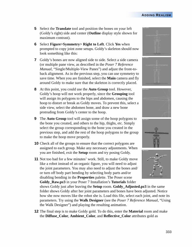
333
ADDING REALISM
5 Select the Translate tool and position the bones on your left (Goldy’s right) side and center (Outline display style shown for maximum contrast).
6 Select Figure>Symmetry> Right to Left. Click Yes when prompted to copy joint zone setups. Goldy’s skeleton should now look something like this:
7 Goldy’s bones are now aligned side to side. Select a side camera (or multiple pane view, as described in the Poser 7 Reference Manual, “Single/Multiple-View Panes”) and adjust the front-to-back alignment. As in the previous step, you can use symmetry to save time. When you are finished, select the Main camera and fly around Goldy to make sure that the skeleton is correctly placed.
8 At this point, you could use the Auto Group tool. However, Goldy’s hoop will not work properly, since the Grouping tool will assign its polygons to the hips and abdomen, causing the hoop to distort or break as Goldy moves. To prevent this, select a side view, select the abdomen bone, and draw a new bone protruding from Goldy’s center to the hoop.
9 The Auto Group tool will assign some of the hoop polygons to the bone you created, and others to the hip, thighs, etc. Simply select the group corresponding to the bone you created in the previous step, and add the rest of the hoop polygons to the group to make the hoop move properly.
10 Check all of the groups to ensure that the correct polygons are assigned to each group. Make any necessary adjustments. When you are finished, exit the Setup room and try posing Goldy.
11 Not too bad for a few minutes’ work. Still, to make Goldy move like a robot instead of an organic figure, you will need to adjust the joint parameters. You may also need to adjust the bones and/or turn off body part bending by selecting body parts and/or disabling bending in the Properties palette. The Poser scene Goldy_Raw.pz3 in your Poser 7 Installation’s Tutorials folder shows Goldy just after leaving the Setup room. Goldy_Adjusted.pz3 in the same folder shows Goldy after her joint parameters and bones have been adjusted. Notice how she now moves like the robot she is. Load this file, select each joint, and note its parameters. Try using the Walk Designer (see the Poser 7 Reference Manual, “Using the Walk Designer”) and playing the resulting animation.
12 The final step is to make Goldy gold. To do this, enter the Material room and make the Diffuse_Color, Ambient_Color, and Reflective_Color attributes gold as
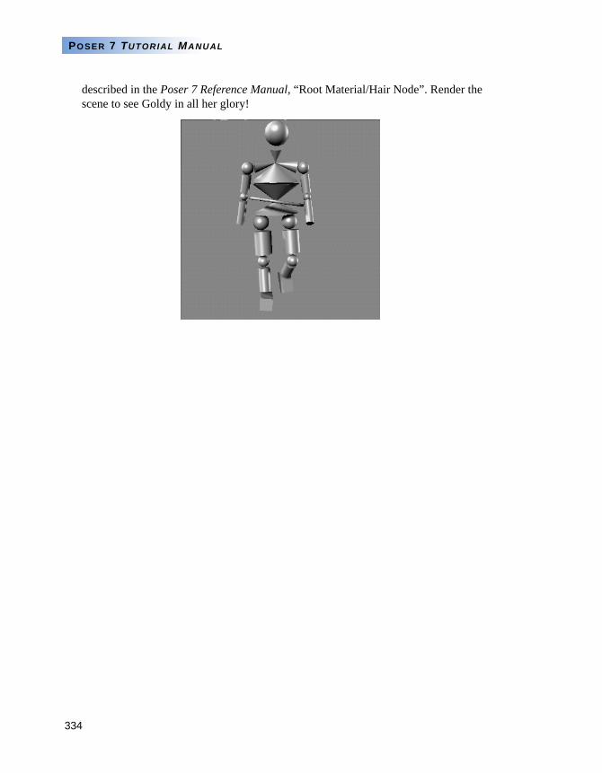
334
POSER 7 TUTORIAL MANUAL
described in the Poser 7 Reference Manual, “Root Material/Hair Node”. Render the scene to see Goldy in all her glory!
335
ADVANCED TECHNIQUES
Chapter 21: Advanced Figure Creation
figure in Poser 7 is basically a 3D model that has separate parts for each moving limb. What makes a Poser 7 model unique is how it interacts with the controls in Poser 7. When a 3D model is within Poser 7, it has joints that move realistically. It seems to move like a real person.
HOW DO YOU MAKE A NEW FIGURE?Poser 7 created the ability to mirror real body movement by adding joint parameters to each body part. This allows you to then manipulate the figure based on those parameters. By using parameter dials and the Walk Designer you can create realistic motion.
To create your own Poser figures, you must set up your model in a way that Poser 7 can understand. Once that is done, you can move or pose your model, just as you would any of the models that are included with Poser 7.
This chapter describes how to create articulated bending figures in Poser 7. The Tutorial starting with “Creating the Initial Figure” on page 348 leads you thorough the entire process step-by-step.
Figure creation is a multi-step process:
Create a 3D model of the new figure.
Create a hierarchy file for the figure.
Convert the hierarchy file.
Locate and use the new figure file in Poser 7.
Verify the figure’s hierarchy.
Adjust the joint parameters of each body part.
Set limits.
Set favored IK angles.
Store the default position.
Set the surface materials for the figure.
Add morph targets to individual body parts.
Set part names
A
336
POSER 7 TUTORIAL MANUAL
Save the new figure to the Library palette.
CREATING FIGURE MODELS
Almost any geometry that is made up of polygons and has individual parts can be used as a figure in Poser 7. What your model looks like makes no difference to how it works in Poser 7. It doesn’t even have to look human, it just needs to be set up properly and stored in the correct format.
Once those two criteria are satisfied you can make anything into a Poser figure. With the right set up, you can make anything from an accordion to a zebra into a poseable figure.
MODEL FORMAT
In order to use geometry as a figure in Poser 7, it must be stored in a Wavefront (.obj) compatible format. As well, you must use only polygons to create your model. Nurbs or spline surfaces are not suitable.
GROUPING
Poser 7 uses a group name as the internal name of a body part inside Poser 7. Some Poser 7 features, like the Walk Designer, require specifically named body parts. The group name is also the default name that you see when working with this body part (you can change that at a later time).
It’s important that groups are set up to denote the individual moving sections. You can store body parts as individual OBJ files or save the entire figure as a single file. In either method, you need to carefully plan how you choose to separate the polygons into individual moving parts.
You do not need to move these parts to the origin individually. You should leave them where they naturally relate to one another. Local origins are set up later inside Poser 7.
When you store each body in a separate wavefront OBJ file you need have only one specified group in each file. That group contains all the polygons in that file.
When you store the entire body in one Wavefront OBJ, you must use “groups” to separate different parts of the body that represent the moving hierarchy. Saving the entire body in one Wavefront OBJ file is usually the preferred method.
It is very important that groups do not overlap. Wavefront grouping allows polygons to be in more than one group. If this happens, the overlapping polygons are duplicated when you bring the file into Poser 7, each group being turned into a separate Poser body part.
For example, if you build a human-like object, you want to separate the polygons of the model into the following groups:
337
ADVANCED TECHNIQUES
rHand lHand head neck lCollar rCollar chest abdomen hip rThigh lThigh rShin lShin rFoot lFoot rShldr lShldr rForeArm lForeArm
In order to use the figure in the Walk Designer you’ll have to make sure that the above groups are used in the figure.
Before creating a hierarchy file, import your OBJ file as a prop to check that the geometry is imported correctly.
Naming Groups
In a Poser figure file, there are actually two names applied to each body part. One name is used internally, the other is what the you see. It is important that certain body parts use standard internal names in order to be available for specific Poser 7 features. The user name (specified by the “name” line of actors) can be anything you wish.
The following body part names (therefore Wavefront group names) should be used when available:
“rHand” -- for the body part that represents the base palm of the right hand
“lHand” -- for the body part that represents the base palm of the left hand.
In order for the hand Library features to work completely, the fingers of the hand should be broken up using the following names (working from root to tip):
rHand rThumb1 rThumb2 rThumb3rIndex1 rIndex2 rIndex3rMid1 rMid2 rMid3rRing1 rRing2 rRing3rPinky1 rPinky2 rPinky3lHandlThumb1 lThumb2 lThumb3lIndex1 lIndex2 lIndex3lMid1 lMid2 lMid3
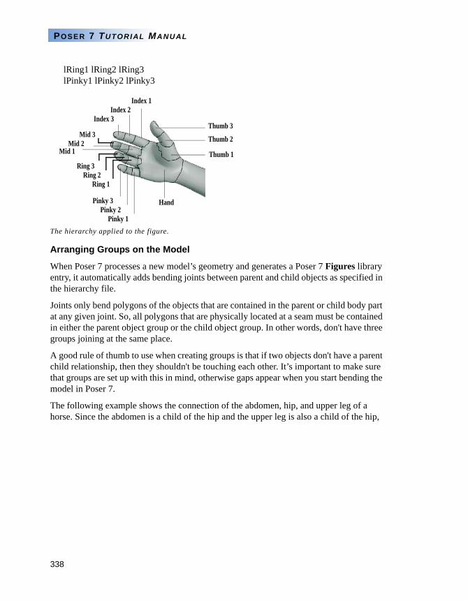
338
POSER 7 TUTORIAL MANUAL
lRing1 lRing2 lRing3lPinky1 lPinky2 lPinky3
Arranging Groups on the Model
When Poser 7 processes a new model’s geometry and generates a Poser 7 Figures library entry, it automatically adds bending joints between parent and child objects as specified in the hierarchy file.
Joints only bend polygons of the objects that are contained in the parent or child body part at any given joint. So, all polygons that are physically located at a seam must be contained in either the parent object group or the child object group. In other words, don't have three groups joining at the same place.
A good rule of thumb to use when creating groups is that if two objects don't have a parent child relationship, then they shouldn't be touching each other. It’s important to make sure that groups are set up with this in mind, otherwise gaps appear when you start bending the model in Poser 7.
The following example shows the connection of the abdomen, hip, and upper leg of a horse. Since the abdomen is a child of the hip and the upper leg is also a child of the hip,
The hierarchy applied to the figure.
Ring 2
Pinky 1
Mid 3
Index 1
Thumb 1
Hand
Thumb 2
Thumb 3
Pinky 2Pinky 3
Index 2Index 3
Mid 2Mid 1
Ring 1
Ring 3
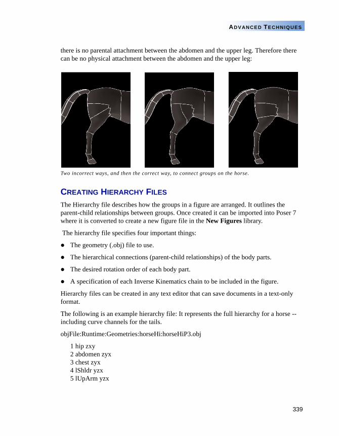
339
ADVANCED TECHNIQUES
there is no parental attachment between the abdomen and the upper leg. Therefore there can be no physical attachment between the abdomen and the upper leg:
CREATING HIERARCHY FILES
The Hierarchy file describes how the groups in a figure are arranged. It outlines the parent-child relationships between groups. Once created it can be imported into Poser 7 where it is converted to create a new figure file in the New Figures library.
The hierarchy file specifies four important things:
The geometry (.obj) file to use.
The hierarchical connections (parent-child relationships) of the body parts.
The desired rotation order of each body part.
A specification of each Inverse Kinematics chain to be included in the figure.
Hierarchy files can be created in any text editor that can save documents in a text-only format.
The following is an example hierarchy file: It represents the full hierarchy for a horse -- including curve channels for the tails.
objFile:Runtime:Geometries:horseHi:horseHiP3.obj
1 hip zxy 2 abdomen zyx3 chest zyx4 lShldr yzx5 lUpArm yzx
Two incorrect ways, and then the correct way, to connect groups on the horse.
340
POSER 7 TUTORIAL MANUAL
6 lForeArm yzx7 lWrist yzx8 lHand yxz4 rShldr yzx5 rUpArm yzx6 rForeArm yzx7 rWrist yzx8 rHand yxz4 lowNeck zyx5 upNeck zyx6 head yzx2lThigh yzx3 lLeg yzx4 lShin yzx5 lAnkle yzx6 lFoot yxz2 rThigh yzx3 rLeg yzx4 rShin yzx5 rAnkle yzx6 rFoot yxz2 tail1 zyx curve3 tail2 zyx curve4 tail3 zyx curve5 tail4 zyx curve
ikChainLeftLeg lThigh lLeg lShin lAnkleikChainRightLeg rThigh rLeg rShin rAnkleikChainLeftHand lShldr lUpArm lForeArm lWrist lHand ikChainRightHand rShldr rUpArm rForeArm rWrist rHand
There are more samples in the Tutorials>Figure Creation folder that is included with your Poser 7 installation.
HIERARCHY FILE EXPLAINED
The following section explains the various parts of the Hierarchy file.
Hierarchy File Header
The first line of the hierarchy file contains the “OBJ File” command which specifies the location of the OBJ file associated with the new figure.
objFile:Runtime:Geometries:horseHi:horseTex.obj
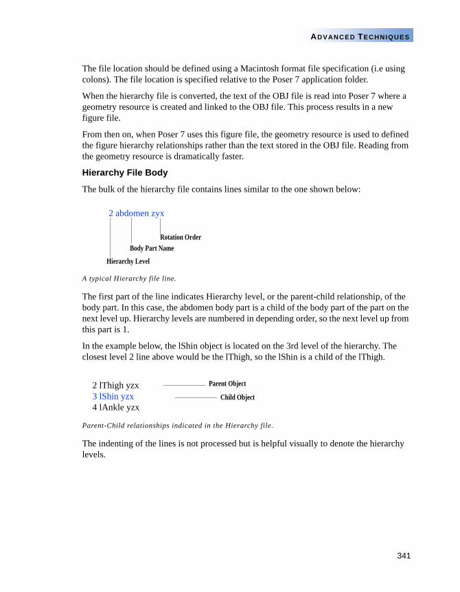
341
ADVANCED TECHNIQUES
The file location should be defined using a Macintosh format file specification (i.e using colons). The file location is specified relative to the Poser 7 application folder.
When the hierarchy file is converted, the text of the OBJ file is read into Poser 7 where a geometry resource is created and linked to the OBJ file. This process results in a new figure file.
From then on, when Poser 7 uses this figure file, the geometry resource is used to defined the figure hierarchy relationships rather than the text stored in the OBJ file. Reading from the geometry resource is dramatically faster.
Hierarchy File Body
The bulk of the hierarchy file contains lines similar to the one shown below:
The first part of the line indicates Hierarchy level, or the parent-child relationship, of the body part. In this case, the abdomen body part is a child of the body part of the part on the next level up. Hierarchy levels are numbered in depending order, so the next level up from this part is 1.
In the example below, the lShin object is located on the 3rd level of the hierarchy. The closest level 2 line above would be the lThigh, so the lShin is a child of the lThigh.
The indenting of the lines is not processed but is helpful visually to denote the hierarchy levels.
A typical Hierarchy file line.
Parent-Child relationships indicated in the Hierarchy file.
Rotation OrderBody Part Name
Hierarchy Level
2 abdomen zyx
2 lThigh yzx3 lShin yzx4 lAnkle yzx
Parent Object
Child Object
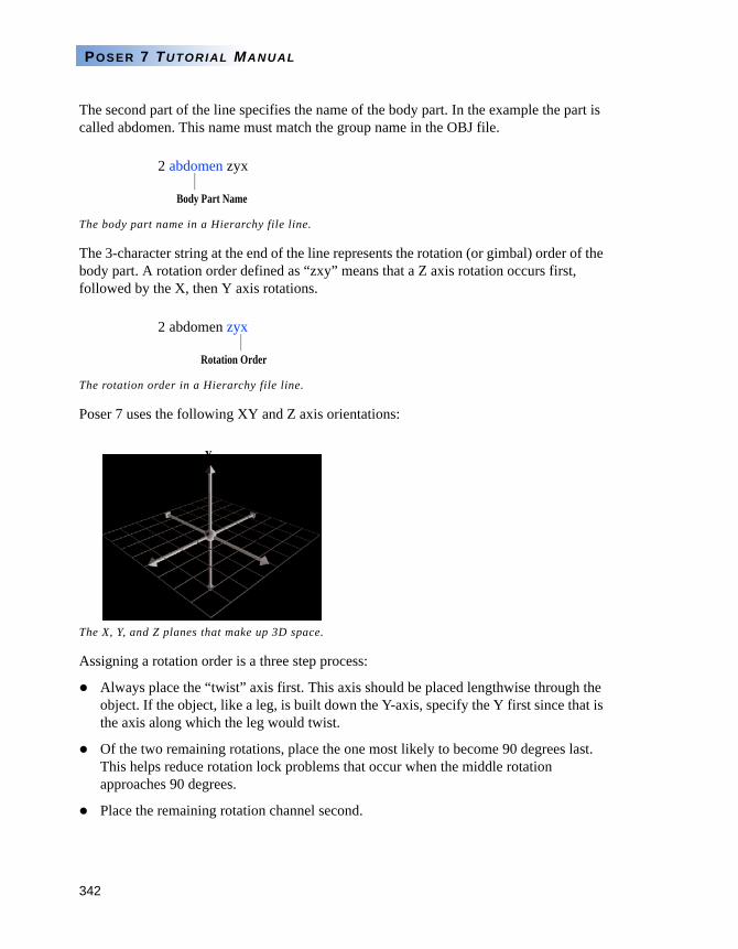
342
POSER 7 TUTORIAL MANUAL
The second part of the line specifies the name of the body part. In the example the part is called abdomen. This name must match the group name in the OBJ file.
The 3-character string at the end of the line represents the rotation (or gimbal) order of the body part. A rotation order defined as “zxy” means that a Z axis rotation occurs first, followed by the X, then Y axis rotations.
Poser 7 uses the following XY and Z axis orientations:
Assigning a rotation order is a three step process:
Always place the “twist” axis first. This axis should be placed lengthwise through the object. If the object, like a leg, is built down the Y-axis, specify the Y first since that is the axis along which the leg would twist.
Of the two remaining rotations, place the one most likely to become 90 degrees last. This helps reduce rotation lock problems that occur when the middle rotation approaches 90 degrees.
Place the remaining rotation channel second.
The body part name in a Hierarchy file line.
The rotation order in a Hierarchy file line.
The X, Y, and Z planes that make up 3D space.
Body Part Name
2 abdomen zyx
Rotation Order
2 abdomen zyx
Y
Z X
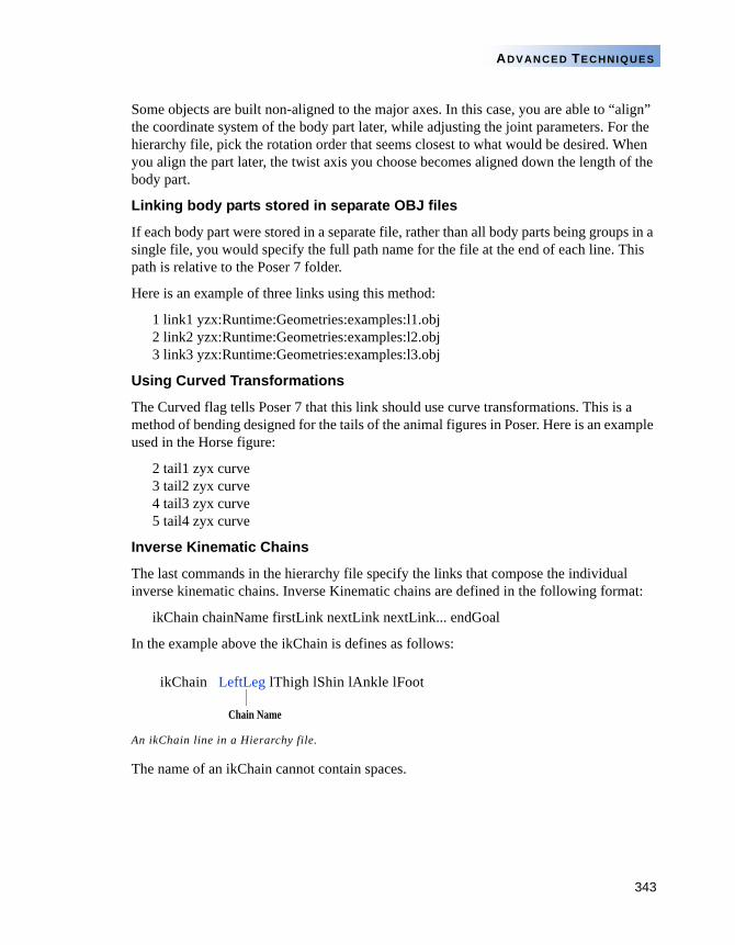
343
ADVANCED TECHNIQUES
Some objects are built non-aligned to the major axes. In this case, you are able to “align” the coordinate system of the body part later, while adjusting the joint parameters. For the hierarchy file, pick the rotation order that seems closest to what would be desired. When you align the part later, the twist axis you choose becomes aligned down the length of the body part.
Linking body parts stored in separate OBJ files
If each body part were stored in a separate file, rather than all body parts being groups in a single file, you would specify the full path name for the file at the end of each line. This path is relative to the Poser 7 folder.
Here is an example of three links using this method:
1 link1 yzx:Runtime:Geometries:examples:l1.obj 2 link2 yzx:Runtime:Geometries:examples:l2.obj 3 link3 yzx:Runtime:Geometries:examples:l3.obj
Using Curved Transformations
The Curved flag tells Poser 7 that this link should use curve transformations. This is a method of bending designed for the tails of the animal figures in Poser. Here is an example used in the Horse figure:
2 tail1 zyx curve 3 tail2 zyx curve 4 tail3 zyx curve 5 tail4 zyx curve
Inverse Kinematic Chains
The last commands in the hierarchy file specify the links that compose the individual inverse kinematic chains. Inverse Kinematic chains are defined in the following format:
ikChain chainName firstLink nextLink nextLink... endGoal
In the example above the ikChain is defines as follows:
The name of an ikChain cannot contain spaces.
An ikChain line in a Hierarchy file.
Chain Name
ikChain LeftLeg lThigh lShin lAnkle lFoot
344
POSER 7 TUTORIAL MANUAL
CONVERTING HIERARCHY FILES
Once the Hierarchy file is completed in the text editor, you can import it into Poser 7 by converting it into a geometry resource (called a CR2 file).
This geometry resource is then used by Poser 7, in conjunction with OBJ 3D data to create a new figure file with rotation order, and Inverse Kinematic relationships as defined by the hierarchy text file.
On Windows, the resource is a separate file ending is RSR. On a Macintosh, the resource is stored with the OBJ file. If you need to edit the resource on a Mac, use a resource editor to remove the text from the OBJ file, or create a new text file by copying and pasting from the old one.
If you make changes to the hierarchy file and then convert it again, the conversion won’t re-create the geometry resource if it already exists in the OBJ file. So, if you are trying to make geometry changes, you need to either delete the resource, or start with a new blank text file that contains only the text portion of the OBJ file.
To convert a Hierarchy file:
1 Choose File menu>Convert Hier File. The Open dialog appears.
2 Locate the Hierarchy file you created in the text editor and click Open.
If there are no errors, a Poser 7 Figure library file is created.
The hierarchy conversion may take several minutes if there is a large geometry file.
The figure file that gets created references the geometry file whenever used. Its location should be established and not moved later or the figure file cannot find the geometry.
If the location is changed you need to edit the figure file with a text editor to designate the new location (specified relative to the Poser 7 application in Mac format).
VERIFYING HIERARCHY FILES
Once you begin adjusting the joints you are not able to regenerate the figure file a second time and have all your joint changes in place. Make sure that all Parent-Child relationships are correct before editing joint parameters. You can make geometry corrections later, but you cannot change the hierarchy without creating different joints from scratch again.
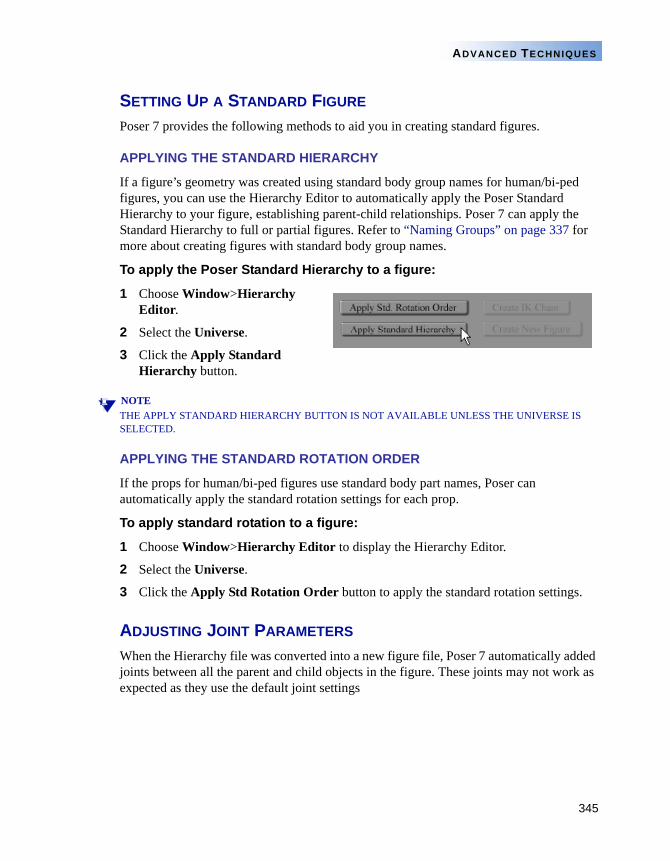
345
ADVANCED TECHNIQUES
SETTING UP A STANDARD FIGURE
Poser 7 provides the following methods to aid you in creating standard figures.
APPLYING THE STANDARD HIERARCHY
If a figure’s geometry was created using standard body group names for human/bi-ped figures, you can use the Hierarchy Editor to automatically apply the Poser Standard Hierarchy to your figure, establishing parent-child relationships. Poser 7 can apply the Standard Hierarchy to full or partial figures. Refer to “Naming Groups” on page 337 for more about creating figures with standard body group names.
To apply the Poser Standard Hierarchy to a figure:
1 Choose Window>Hierarchy Editor.
2 Select the Universe.
3 Click the Apply Standard Hierarchy button.
NOTETHE APPLY STANDARD HIERARCHY BUTTON IS NOT AVAILABLE UNLESS THE UNIVERSE IS SELECTED.
APPLYING THE STANDARD ROTATION ORDER
If the props for human/bi-ped figures use standard body part names, Poser can automatically apply the standard rotation settings for each prop.
To apply standard rotation to a figure:
1 Choose Window>Hierarchy Editor to display the Hierarchy Editor.
2 Select the Universe.
3 Click the Apply Std Rotation Order button to apply the standard rotation settings.
ADJUSTING JOINT PARAMETERS
When the Hierarchy file was converted into a new figure file, Poser 7 automatically added joints between all the parent and child objects in the figure. These joints may not work as expected as they use the default joint settings
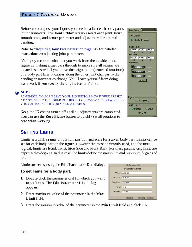
346
POSER 7 TUTORIAL MANUAL
Before you can pose your figure, you need to adjust each body part’s joint parameters. The Joint Editor lets you select each joint, twist, smooth scale, and center parameter and adjust them for optimal bending.
Refer to “Adjusting Joint Parameters” on page 345 for detailed instructions on adjusting joint parameters.
It’s highly recommended that you work from the outside of the figure in, making a first pass through to make sure all origins are located as desired. If you move the origin point (center of rotations) of a body part later, it carries along the other joint changes so the bending characteristics change. You’ll save yourself from doing extra work if you specify the origins (centers) first.
NOTEREMEMBER, YOU CAN SAVE YOUR FIGURE TO A NEW FIGURE PRESET AT ANY TIME. YOU SHOULD DO THIS PERIODICALLY AS YOU WORK SO YOU CAN BACK UP IF YOU MAKE MISTAKES.
Keep the IK chains turned off until all adjustments are completed. You can use the Zero Figure button to quickly set all rotations to zero while working.
SETTING LIMITS
Limits establish a range of rotation, position and scale for a given body part. Limits can be set for each body part on the figure. However the most commonly used, and the most logical, limits are Bend, Twist, Side-Side and Front-Back. For these parameters, limits are expressed as degrees. In this case, the limits define the maximum and minimum degrees of rotation.
Limits are set by using the Edit Parameter Dial dialog.
To set limits for a body part:
1 Double-click the parameter dial for which you want to set limits. The Edit Parameter Dial dialog appears.
2 Enter maximum value of the parameter in the Max Limit field.
3 Enter the minimum value of the parameter in the Min Limit field and click OK.
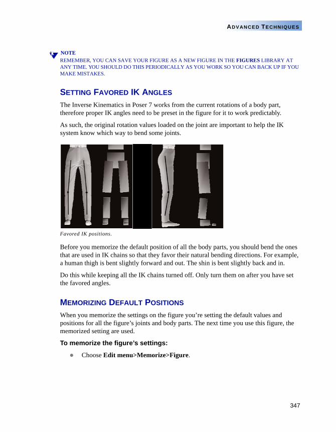
347
ADVANCED TECHNIQUES
NOTEREMEMBER, YOU CAN SAVE YOUR FIGURE AS A NEW FIGURE IN THE FIGURES LIBRARY AT ANY TIME. YOU SHOULD DO THIS PERIODICALLY AS YOU WORK SO YOU CAN BACK UP IF YOU MAKE MISTAKES.
SETTING FAVORED IK ANGLES
The Inverse Kinematics in Poser 7 works from the current rotations of a body part, therefore proper IK angles need to be preset in the figure for it to work predictably.
As such, the original rotation values loaded on the joint are important to help the IK system know which way to bend some joints.
Before you memorize the default position of all the body parts, you should bend the ones that are used in IK chains so that they favor their natural bending directions. For example, a human thigh is bent slightly forward and out. The shin is bent slightly back and in.
Do this while keeping all the IK chains turned off. Only turn them on after you have set the favored angles.
MEMORIZING DEFAULT POSITIONS
When you memorize the settings on the figure you’re setting the default values and positions for all the figure’s joints and body parts. The next time you use this figure, the memorized setting are used.
To memorize the figure’s settings:
Choose Edit menu>Memorize>Figure.
Favored IK positions.
348
POSER 7 TUTORIAL MANUAL
SETTING SURFACE MATERIALS
Please refer to the Poser 7 Reference Guide, “Chapter 16: The Material Room” for more information about applying surface materials to your objects and figures.
ADDING MORPH TARGETS
If you have created wavefront format OBJ files that have the identical vertex ordering as any individual body part, you can load them as morph targets.
Refer to “Setting Up Morph Targets” on page 308 for more on setting Morph Targets.
SETTING BODY PART NAMES
The names of the groups you set up in the OBJ file and Hierarchy file may not be the most descriptive names you can use. Once the main parameters are set for the figure, you can change the name of each body part.
To change the name of a body part:
1 Double-click a body part. The Properties palette for that body part appears.
2 Enter a new name in the Name field.
SAVING NEW FIGURES TO THE LIBRARY
After you’re finished setting joint parameters and body part names, you can save the final figure to the Figures category in the Libary palette where it can be recalled at any time.
Refer to the Poser 7 Reference Manual, “Chapter 5: The Poser 7 Library” for more information on saving figures to the Library palette.
TUTORIAL - POSER FIGURE CREATION
In this tutorial, a 3D polygon mesh object is converted into a Poser figure. We assume that you are familiar with 3D modeling applications, such as Shade, and have the ability to generate or modify 3D mesh objects.
Creating the Initial Figure
To create the initial figure:
1 Using your favorite 3D modeling application, open or generate a female human figure mesh object.
2 Name the body part groups in a manner consistent with Poser 7’s body part naming format. See “Grouping” on page 336 for more information on naming groups.
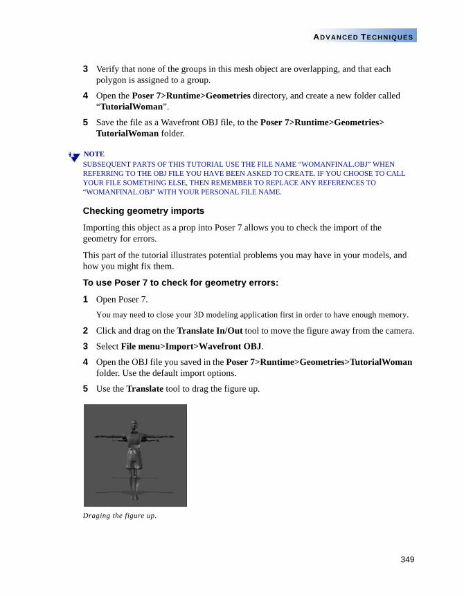
349
ADVANCED TECHNIQUES
3 Verify that none of the groups in this mesh object are overlapping, and that each polygon is assigned to a group.
4 Open the Poser 7>Runtime>Geometries directory, and create a new folder called “TutorialWoman”.
5 Save the file as a Wavefront OBJ file, to the Poser 7>Runtime>Geometries> TutorialWoman folder.
NOTESUBSEQUENT PARTS OF THIS TUTORIAL USE THE FILE NAME “WOMANFINAL.OBJ” WHEN REFERRING TO THE OBJ FILE YOU HAVE BEEN ASKED TO CREATE. IF YOU CHOOSE TO CALL YOUR FILE SOMETHING ELSE, THEN REMEMBER TO REPLACE ANY REFERENCES TO “WOMANFINAL.OBJ” WITH YOUR PERSONAL FILE NAME.
Checking geometry imports
Importing this object as a prop into Poser 7 allows you to check the import of the geometry for errors.
This part of the tutorial illustrates potential problems you may have in your models, and how you might fix them.
To use Poser 7 to check for geometry errors:
1 Open Poser 7.
You may need to close your 3D modeling application first in order to have enough memory.
2 Click and drag on the Translate In/Out tool to move the figure away from the camera.
3 Select File menu>Import>Wavefront OBJ.
4 Open the OBJ file you saved in the Poser 7>Runtime>Geometries>TutorialWoman folder. Use the default import options.
5 Use the Translate tool to drag the figure up.
Draging the figure up.
350
POSER 7 TUTORIAL MANUAL
Fixing surface normals
If you notice that some areas seem to have holes or appear inverted, this is because the surface normals are flipped. You can fix this in your 3D modeling application.
Creating the Hierarchy File
You must create a hierarchy file in order to import the figure back into Poser 7. See “Creating Hierarchy Files” on page 339 for details on the syntax of the hierarchy file.
To create the hierarchy file:
1 Create your hierarchy file to appear as follows:
objFile:Runtime:Geometries:TutorialWoman:womanfinal.obj
1 hip zxy2 abdomen yxz3 chest zyx4 neck yxz5 head yxz6 lEye yxz6 rEye yxz6 mouth yxz4 lShldr xzy5 lUpperarm xyz6 lForearm xyz7 lHand xyz4 rShldr xzy5 rUpperarm xyz6 rForearm xyz7 rHand xyz2 lPant yxz3 lThigh yxz4 lCalf yxz5 lFoot zxy2 rPant yxz3 rThigh yxz4 rCalf yxz5 rFoot yzx
ikChain lArm lShldr lUpperarm lForearm lHand
ikChain rArm rShldr rUpperarm rForearm rHand
ikChain lLeg lPant lThigh lCalf lFoot
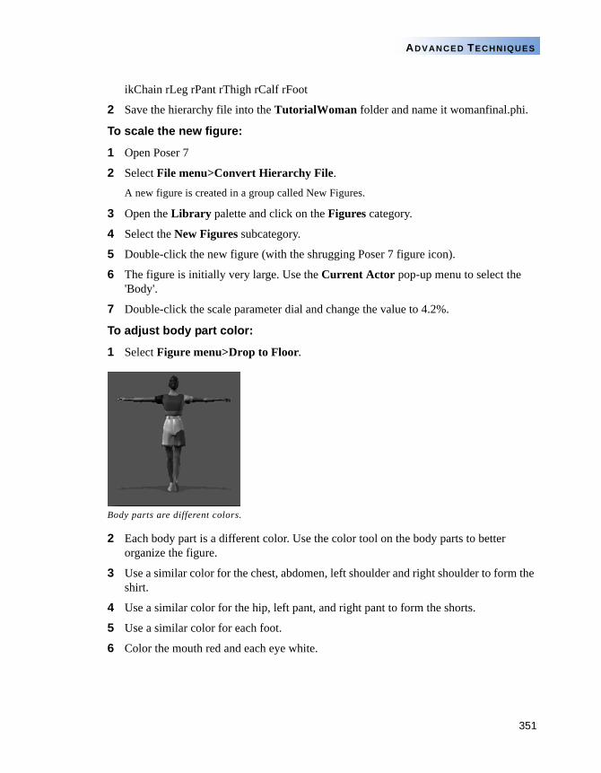
351
ADVANCED TECHNIQUES
ikChain rLeg rPant rThigh rCalf rFoot
2 Save the hierarchy file into the TutorialWoman folder and name it womanfinal.phi.
To scale the new figure:
1 Open Poser 7
2 Select File menu>Convert Hierarchy File.A new figure is created in a group called New Figures.
3 Open the Library palette and click on the Figures category.
4 Select the New Figures subcategory.
5 Double-click the new figure (with the shrugging Poser 7 figure icon).
6 The figure is initially very large. Use the Current Actor pop-up menu to select the 'Body'.
7 Double-click the scale parameter dial and change the value to 4.2%.
To adjust body part color:
1 Select Figure menu>Drop to Floor.
2 Each body part is a different color. Use the color tool on the body parts to better organize the figure.
3 Use a similar color for the chest, abdomen, left shoulder and right shoulder to form the shirt.
4 Use a similar color for the hip, left pant, and right pant to form the shorts.
5 Use a similar color for each foot.
6 Color the mouth red and each eye white.
Body parts are different colors.
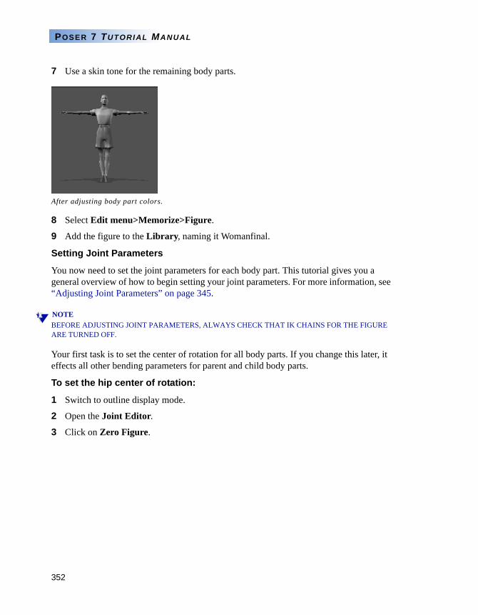
352
POSER 7 TUTORIAL MANUAL
7 Use a skin tone for the remaining body parts.
8 Select Edit menu>Memorize>Figure.
9 Add the figure to the Library, naming it Womanfinal.
Setting Joint Parameters
You now need to set the joint parameters for each body part. This tutorial gives you a general overview of how to begin setting your joint parameters. For more information, see “Adjusting Joint Parameters” on page 345.
NOTEBEFORE ADJUSTING JOINT PARAMETERS, ALWAYS CHECK THAT IK CHAINS FOR THE FIGURE ARE TURNED OFF.
Your first task is to set the center of rotation for all body parts. If you change this later, it effects all other bending parameters for parent and child body parts.
To set the hip center of rotation:
1 Switch to outline display mode.
2 Open the Joint Editor.
3 Click on Zero Figure.
After adjusting body part colors.
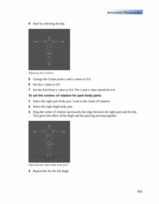
353
ADVANCED TECHNIQUES
4 Start by selecting the hip.
5 Change the Center point x and z values to 0.0.
6 Set the y value to 0.9.
7 Set the End Point y value to 0.8. The x and z value should be 0.0.
To set the centers of rotation for pant body parts:
1 Select the right pant body part. Look at the center of rotation.
2 Select the right thigh body part.
3 Drag the center of rotation up towards the edge between the right pant and the hip. This gives the effect of the thigh and the pant leg moving together.
4 Repeat this for the left thigh.
Adjusting hip rotation.
Adjusting the right thigh body part.
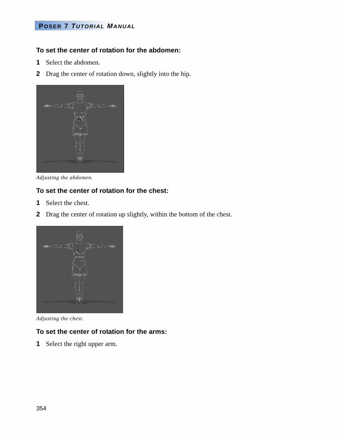
354
POSER 7 TUTORIAL MANUAL
To set the center of rotation for the abdomen:
1 Select the abdomen.
2 Drag the center of rotation down, slightly into the hip.
To set the center of rotation for the chest:
1 Select the chest.
2 Drag the center of rotation up slightly, within the bottom of the chest.
To set the center of rotation for the arms:
1 Select the right upper arm.
Adjusting the abdomen.
Adjusting the chest.
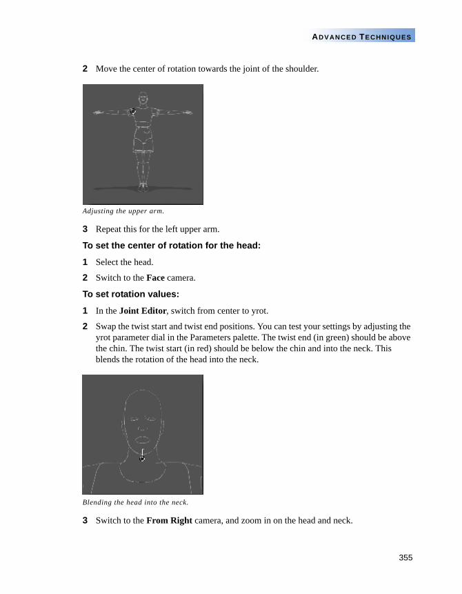
355
ADVANCED TECHNIQUES
2 Move the center of rotation towards the joint of the shoulder.
3 Repeat this for the left upper arm.
To set the center of rotation for the head:
1 Select the head.
2 Switch to the Face camera.
To set rotation values:
1 In the Joint Editor, switch from center to yrot.
2 Swap the twist start and twist end positions. You can test your settings by adjusting the yrot parameter dial in the Parameters palette. The twist end (in green) should be above the chin. The twist start (in red) should be below the chin and into the neck. This blends the rotation of the head into the neck.
3 Switch to the From Right camera, and zoom in on the head and neck.
Adjusting the upper arm.
Blending the head into the neck.
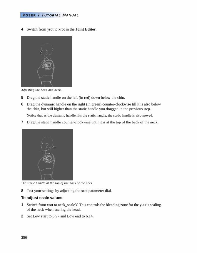
356
POSER 7 TUTORIAL MANUAL
4 Switch from yrot to xrot in the Joint Editor.
5 Drag the static handle on the left (in red) down below the chin.
6 Drag the dynamic handle on the right (in green) counter-clockwise till it is also below the chin, but still higher than the static handle you dragged in the previous step.
Notice that as the dynamic handle hits the static handle, the static handle is also moved.
7 Drag the static handle counter-clockwise until it is at the top of the back of the neck.
8 Test your settings by adjusting the xrot parameter dial.
To adjust scale values:
1 Switch from xrot to neck_scaleY. This controls the blending zone for the y-axis scaling of the neck when scaling the head.
2 Set Low start to 5.97 and Low end to 6.14.
Adjusting the head and neck.
The static handle at the top of the back of the neck.
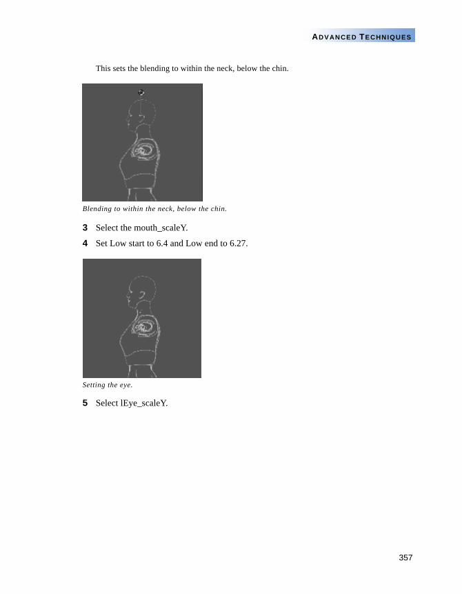
357
ADVANCED TECHNIQUES
This sets the blending to within the neck, below the chin.
3 Select the mouth_scaleY.
4 Set Low start to 6.4 and Low end to 6.27.
5 Select lEye_scaleY.
Blending to within the neck, below the chin.
Setting the eye.
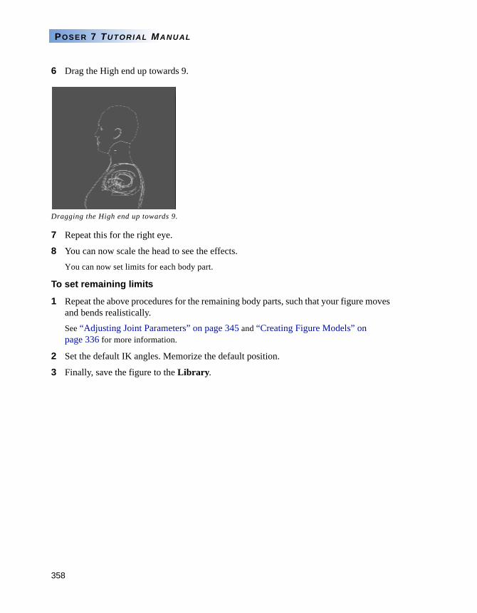
358
POSER 7 TUTORIAL MANUAL
6 Drag the High end up towards 9.
7 Repeat this for the right eye.
8 You can now scale the head to see the effects.
You can now set limits for each body part.
To set remaining limits
1 Repeat the above procedures for the remaining body parts, such that your figure moves and bends realistically. See “Adjusting Joint Parameters” on page 345 and “Creating Figure Models” on page 336 for more information.
2 Set the default IK angles. Memorize the default position.
3 Finally, save the figure to the Library.
Dragging the High end up towards 9.