tutorial solidworks 2011
TRANSCRIPT

What's NewSOLIDWORKS 2011

Contents
What's New: Highlights of SolidWorks 2011....................................................................ixLegal Notices..................................................................................................................11
1 User Interface...............................................................................................................13SolidWorks Search................................................................................................................................13Save As and File Properties Buttons on Standard Toolbar ..................................................................13PropertyManager Icons..........................................................................................................................13Error Reporting......................................................................................................................................14
2 SolidWorks Fundamentals...........................................................................................15Application Programming Interface........................................................................................................15Pack and Go..........................................................................................................................................16Documentation.......................................................................................................................................16
New Tutorials....................................................................................................................................16Toolbox Administration Overview.....................................................................................................16
3 3D ContentCentral.......................................................................................................17Defeature Tool.......................................................................................................................................17Configuration Publisher..........................................................................................................................173D ContentCentral for Suppliers............................................................................................................17
4 Administration..............................................................................................................19Converting Files to SolidWorks 2011.....................................................................................................19Installation Improvements......................................................................................................................19SolidWorks Rx.......................................................................................................................................21
Diagnostics.......................................................................................................................................21Usability and Workflow Improvements.............................................................................................21Hardware Benchmarks.....................................................................................................................22Graphics Card Health Checker........................................................................................................22
5 Assemblies...................................................................................................................23Assembly Features................................................................................................................................23
Fillets and Chamfers ........................................................................................................................23Weld Beads .....................................................................................................................................23
Assembly Visualization..........................................................................................................................24Defeature for Assemblies ......................................................................................................................25
Defeature - Step 1: Components......................................................................................................25Defeature - Step 2: Motion...............................................................................................................26Defeature - Step 3: To Keep.............................................................................................................26Defeature - Step 4: To Remove.......................................................................................................27
ii

Defeature - Feature Removal Complete..........................................................................................28Equations...............................................................................................................................................29Interference Detection............................................................................................................................29
Ignore Hidden Bodies.......................................................................................................................29Quality and Performance..................................................................................................................29
Mates.....................................................................................................................................................29Replace Mate Entities.......................................................................................................................29Mates in Motion................................................................................................................................30
Rebuild Report.......................................................................................................................................30SpeedPak..............................................................................................................................................30
6 CircuitWorks.................................................................................................................32User-Defined Coordinates for Component Orientation..........................................................................32Interface Improvements.........................................................................................................................34Workflow Improvements........................................................................................................................34Comparing Boards.................................................................................................................................35Export to PADS PowerPCB Format.......................................................................................................35
7 Configurations..............................................................................................................36Configuration Publisher..........................................................................................................................36
3D ContentCentral............................................................................................................................36Parent/Child Relationships...............................................................................................................37
Modify Configurations............................................................................................................................37Parameters............................................................................................................................................37SpeedPak..............................................................................................................................................38
8 Design Checker............................................................................................................39Design Checker Standards from SolidWorks Files................................................................................39File Location Check...............................................................................................................................39Dimension Precision Check...................................................................................................................40Feature Positioning Check.....................................................................................................................40Standard Template Check.....................................................................................................................40Design Checker Report..........................................................................................................................40Summary Report for Task Scheduler....................................................................................................40Design Checker Task in Enterprise PDM..............................................................................................41
9 DFMXpress..................................................................................................................42Injection Molding....................................................................................................................................42Running an Injection Molding Check.....................................................................................................42
10 Drawings and Detailing..............................................................................................43Alignment Options for Dimension Palette .............................................................................................43Auto Arrange Dimensions .....................................................................................................................49
Using Auto Arrange Dimensions......................................................................................................49Adjusting Spacing.............................................................................................................................50
Bounding Box for Sheet Metal...............................................................................................................50
iii
Contents

Cut List Properties in Drawings..............................................................................................................52Center Marks in Assembly Drawings.....................................................................................................52Cosmetic Threads..................................................................................................................................53Display Scale in Orthogonal Views........................................................................................................54Drawing Sheet Format...........................................................................................................................54Dual Dimensions for Chamfers..............................................................................................................54Hide Bodies in Drawing View.................................................................................................................55
Hiding a Body...................................................................................................................................55Showing a Body................................................................................................................................55
Hole Tables............................................................................................................................................55Tags..................................................................................................................................................55Dual Unit Support ............................................................................................................................56
Merge and Unmerge Cells in Tables.....................................................................................................56Notes......................................................................................................................................................57
Fit Text in Notes...............................................................................................................................57Pattern Notes....................................................................................................................................57
Show Dimension Units...........................................................................................................................58Show Model Colors in Drawings............................................................................................................58GB Drafting Standard.............................................................................................................................59ANSI Drafting Standard.........................................................................................................................59
Datum Feature Symbols...................................................................................................................59Geometric Tolerance Symbols.........................................................................................................60
3D Drawing Views..................................................................................................................................61
11 DriveWorksXpress.....................................................................................................62Task Pane Interface...............................................................................................................................62
12 eDrawings.................................................................................................................63Display Enhancements..........................................................................................................................63File Synchronization...............................................................................................................................63Triad Manipulation.................................................................................................................................63Filtering by Component Name...............................................................................................................63Native 64-Bit Support.............................................................................................................................64
13 Enterprise PDM..........................................................................................................65File Explorer and SolidWorks Add-in.....................................................................................................65
Enterprise PDM Menus ...................................................................................................................65Expanded Search Capability............................................................................................................67Expanded File Open Capabilities.....................................................................................................67Updating Broken File References....................................................................................................68Saving eDrawings Markup Files.......................................................................................................68Restoring Files from Cold Storage...................................................................................................69Creating Submenus..........................................................................................................................69
Administration Tool................................................................................................................................70Collecting Support Information.........................................................................................................70
iv
Contents

Group Import from Active Directory..................................................................................................703DVIA Composer File Format Support.............................................................................................71Design Checker Validation...............................................................................................................71Aliases in Card Lists.........................................................................................................................72Arithmetic and String Functions in Input Formulas...........................................................................73Exported Workflow Links..................................................................................................................74Associating Drawing Types with File Types.....................................................................................74
API.........................................................................................................................................................75Adding Commands to Submenus.....................................................................................................75Using an Add-in to Define Item Explorer Menu Commands.............................................................75Updating the BOM Quantity Using the API......................................................................................76
Installation..............................................................................................................................................76SQL-DMO Drivers............................................................................................................................76
14 Flow Simulation..........................................................................................................77Electronic Cooling Module.....................................................................................................................77HVAC Design.........................................................................................................................................77
15 Import/Export..............................................................................................................79Exporting .IFC Files...............................................................................................................................79DXF DWG Import Wizard.......................................................................................................................79
Importing Layers from .DWG or .DXF Files......................................................................................79Defining the Sketch Origin and Orientation on .DWG or .DXF Import..............................................79Filtering Sketch Entities on .DWG or .DXF Import...........................................................................80Repairing Sketches After .DWG or .DXF Import..............................................................................80
Exporting Sheet Metal Parts to DXF or DWG Files...............................................................................80Exporting a Bounding Box................................................................................................................80Exporting Bend Line Directions........................................................................................................81
16 Large Scale Design....................................................................................................82Walk-through..........................................................................................................................................82Exporting .IFC Files...............................................................................................................................83Grid System...........................................................................................................................................84
17 Model Display.............................................................................................................86DisplayManager ....................................................................................................................................86Appearances..........................................................................................................................................86Lights.....................................................................................................................................................87Scenes...................................................................................................................................................88Decals....................................................................................................................................................89PhotoView 360 ......................................................................................................................................90
PhotoView Integrated Preview.........................................................................................................90PhotoView Preview Window.............................................................................................................90Motion...............................................................................................................................................91PhotoView Support on 64-bit Computers.........................................................................................91
Working with Appearances and Rendering a Model..............................................................................91
v
Contents

Learning About the DisplayManager................................................................................................91Adding and Editing an Appearance..................................................................................................91Adding a Decal.................................................................................................................................93Changing Another Appearance on the Model..................................................................................94Preparing to Render: Working with Lighting and Scenes.................................................................94Performing a Final Render...............................................................................................................95
18 Mold Design...............................................................................................................96Manual Mode for Creating Parting Surfaces..........................................................................................96
19 Motion Studies...........................................................................................................98Function Builder for Force and Motor Functions....................................................................................98User Interface Changes.........................................................................................................................99Reflected Load Inertia and Reflected Load Mass..................................................................................99Reference Components for Linear Couplers.........................................................................................99Motion Along a Path.............................................................................................................................100
20 Parts and Features...................................................................................................101Parts.....................................................................................................................................................101
Defeature for Parts ........................................................................................................................101Equations........................................................................................................................................101Global Variables.............................................................................................................................106
Features...............................................................................................................................................107Helix................................................................................................................................................107Revolve...........................................................................................................................................108Scale...............................................................................................................................................109
Surfaces...............................................................................................................................................109Surface Extrudes From a 2D or 3D Face ......................................................................................109Capping an Extruded Surface........................................................................................................115
FeatureWorks......................................................................................................................................115Bosses and Cuts Recognition........................................................................................................115Automatic Recognition of Draft Features.......................................................................................118Combining Like Features During Automatic Feature Recognition.................................................118
21 Routing.....................................................................................................................120Routing Library Manager.....................................................................................................................120Route Along Existing Geometry...........................................................................................................121Weld Gaps...........................................................................................................................................121Autosize...............................................................................................................................................122Moving and Rotating a Fitting .............................................................................................................122P&ID Import.........................................................................................................................................123P&ID Report.........................................................................................................................................123Routing Options in Isolate....................................................................................................................123
22 Sheet Metal..............................................................................................................125Bend Calculation Tables......................................................................................................................125
vi
Contents

Convert to Sheet Metal........................................................................................................................125Flat Patterns.........................................................................................................................................127K-Factor in Configurations...................................................................................................................127Mapping Bend Directions When Exporting to DXF/DWG Files...........................................................128Mirroring Edge Flanges and Miter Flanges..........................................................................................128Sheet Metal Properties........................................................................................................................128Patterns of Edge Flanges and Tab Features.......................................................................................129
23 Simulation...............................................................................................................130New Simulation Studies.......................................................................................................................130
New 2D Simplification Study (Professional) ..................................................................................130New Response Spectrum Analysis Study (Premium)....................................................................139
Interface...............................................................................................................................................144Organization of Bodies...................................................................................................................144Filtering the Simulation Study Tree................................................................................................144Display Enhancements for Simulation Studies...............................................................................146Display of Simulation Symbols.......................................................................................................146Expressions in Input Fields............................................................................................................146
Shells...................................................................................................................................................146Offsets for Shells............................................................................................................................146Ply Orientation in Composites (Premium)......................................................................................147Composite Stack Information (Premium).......................................................................................148
Beams..................................................................................................................................................149Non-uniform and Partial Loading of Beams...................................................................................149Tapered Beams..............................................................................................................................150
Connectors...........................................................................................................................................151European Standard for Edge Welds (Professional).......................................................................151
Contact.................................................................................................................................................152Automatic Option for Simplified Bonding........................................................................................152
Mesh....................................................................................................................................................152Mesh Enhancements......................................................................................................................152
Nonlinear Studies.................................................................................................................................152Improved Accuracy for Nonlinear fixtures (Premium).....................................................................152
Results.................................................................................................................................................152Nonlinear Plots (Premium).............................................................................................................152Heat Power and Heat Energy.........................................................................................................153Interaction with List Result Tables..................................................................................................153Probe Callout Enhancements.........................................................................................................153Sensors for Transient Studies........................................................................................................155Study Reports.................................................................................................................................155
24 Sketching.................................................................................................................158Grid System.........................................................................................................................................158
25 Sustainability............................................................................................................160
vii
Contents

New Supported Regions......................................................................................................................160Sustainability Link for Custom Material................................................................................................160
26 SolidWorks Utilities..................................................................................................161Symmetry Check Utility........................................................................................................................161Find/Modify/Suppress Feature Selection.............................................................................................162
27 Toolbox ...................................................................................................................163Opening Models with Referenced Toolbox Components....................................................................163Gears in the GB Standard....................................................................................................................163
28 Weldments...............................................................................................................164Cut Lists...............................................................................................................................................164
Cut List Icons..................................................................................................................................164Reordering and Excluding Cut List Items.......................................................................................164
Weld Beads .........................................................................................................................................164Weld Bead Display ........................................................................................................................165Weld Beads in Assemblies.............................................................................................................165
Weld Support in Drawings ..................................................................................................................169Weld Symbols.................................................................................................................................169Weld Tables....................................................................................................................................169
viii
Contents

What's New: Highlights ofSolidWorks 2011
SolidWorks® 2011 includes manyenhancements and improvements, mostin direct response to customer requests.This release focuses on the followingthemes:
• Design faster and more efficiently• Improved collaboration andvisualization
• Enhanced support for manufacturing
Top EnhancementsThe top enhancements for SolidWorks 2011 provide improvements to existing products andinnovative new functionality. Throughout this guide, look for the symbol in these areas:
Fillets and Chamfers on page 23Assemblies
Weld Bead Display on page 165
Defeature for Assemblies on page 25
Alignment Options for Dimension Palette on page 43Drawings andDetailing
Auto Arrange Dimensions on page 49
Dual Unit Support on page 56
Weld Support in Drawings on page 169
Enterprise PDM Menus on page 65Enterprise PDM
DisplayManager on page 86Model Display
PhotoView 360 on page 90
Defeature for Parts on page 101Parts and Features
Sharing Equations Among Models on page 101
Suppression States of Features and Components on page103
ix

Surface Extrudes From a 2D or 3D Face on page 109
New 2D Simplification Study (Professional) on page 130Simulation
Weld Beads on page 164Weldments
Weld Bead Display on page 165
Fillets and Chamfers on page 166
For More InformationUse the following resources to learn about SolidWorks:
This guide is available in PDF and HTML formats. Click:What's New in PDFand HTML • Help > What's New > PDF
• Help > What's New > HTML
In SolidWorks, click the symbol to display the section of thismanual that describes an enhancement. The symbol appears next
Interactive What'sNew
to new menu items and the titles of new and changedPropertyManagers.
To enable Interactive What's New, click Help > What's New >Interactive.
What's New Examples are updated at every major release to provideexamples of how to use most top enhancements in the release.
To open What 's New Examples click Help >What's New >What'sNew Examples.
What's New Examples
Contains complete coverage of our products, including details aboutthe user interface, samples, and examples.
Online Help
Provides information about late changes to our products.Release Notes
x

Legal Notices© 1995-2010, Dassault Systèmes SolidWorks Corporation, a Dassault Systèmes S.A.company, 300 Baker Avenue, Concord, Mass. 01742 USA. All Rights Reserved.
The information and the software discussed in this document are subject to change withoutnotice and are not commitments by Dassault Systèmes SolidWorks Corporation (DSSolidWorks).
No material may be reproduced or transmitted in any form or by any means, electronicallyor manually, for any purpose without the express written permission of DS SolidWorks.
The software discussed in this document is furnished under a license and may be usedor copied only in accordance with the terms of the license. All warranties given by DSSolidWorks as to the software and documentation are set forth in the license agreement,and nothing stated in, or implied by, this document or its contents shall be consideredor deemed a modification or amendment of any terms, including warranties, in the licenseagreement.
Patent NoticesSolidWorks
®3D mechanical CAD software is protected by U.S. Patents 5,815,154;
6,219,049; 6,219,055; 6,611,725; 6,844,877; 6,898,560; 6,906,712; 7,079,990;7,477,262; 7,558,705; 7,571,079; 7,590,497; 7,643,027; 7,672,822; 7,688,318;7,694,238; and foreign patents, (e.g., EP 1,116,190 and JP 3,517,643).
eDrawings®software is protected by U.S. Patent 7,184,044; U.S. Patent 7,502,027; and
Canadian Patent 2,318,706.
U.S. and foreign patents pending.
Trademarks and Product Names for SolidWorks Products andServicesSolidWorks, 3D PartStream.NET, 3D ContentCentral, eDrawings, and the eDrawings logoare registered trademarks and FeatureManager is a jointly owned registered trademarkof DS SolidWorks.
CircuitWorks, Feature Palette, FloXpress, PhotoWorks, TolAnalyst, and XchangeWorksare trademarks of DS SolidWorks.
FeatureWorks is a registered trademark of Geometric Ltd.
SolidWorks 2011, SolidWorks Enterprise PDM, SolidWorks Simulation, SolidWorks FlowSimulation, and eDrawings Professional are product names of DS SolidWorks.
Other brand or product names are trademarks or registered trademarks of their respectiveholders.
COMMERCIAL COMPUTER SOFTWARE - PROPRIETARY
U.S. Government Restricted Rights. Use, duplication, or disclosure by the government issubject to restrictions as set forth in FAR 52.227-19 (Commercial Computer Software -Restricted Rights), DFARS 227.7202 (Commercial Computer Software and CommercialComputer Software Documentation), and in the license agreement, as applicable.
Contractor/Manufacturer:
11

Dassault Systèmes SolidWorks Corporation, 300 Baker Avenue, Concord, Massachusetts01742 USA
Copyright Notices for SolidWorks Standard, Premium, Professional,and Education ProductsPortions of this software © 1986-2010 Siemens Product Lifecycle Management SoftwareInc. All rights reserved.
Portions of this software © 1986-2010 Siemens Industry Software Limited. All rightsreserved.
Portions of this software © 1998-2010 Geometric Ltd.
Portions of this software © 1996-2010 Microsoft Corporation. All rights reserved.
Portions of this software incorporate PhysX™ by NVIDIA 2006-2010.
Portions of this software © 2001 - 2010 Luxology, Inc. All rights reserved, Patents Pending.
Portions of this software © 2007 - 2010 DriveWorks Ltd.
Copyright 1984-2010 Adobe Systems Inc. and its licensors. All rights reserved. Protectedby U.S. Patents 5,929,866; 5,943,063; 6,289,364; 6,563,502; 6,639,593; 6,754,382;Patents Pending.
Adobe, the Adobe logo, Acrobat, the Adobe PDF logo, Distiller and Reader are registeredtrademarks or trademarks of Adobe Systems Inc. in the U.S. and other countries.
For more copyright information, in SolidWorks see Help > About SolidWorks.
Copyright Notices for SolidWorks Simulation ProductsPortions of this software © 2008 Solversoft Corporation.
PCGLSS © 1992-2007 Computational Applications and System Integration, Inc. All rightsreserved.
Copyright Notices for Enterprise PDM ProductOutside In® Viewer Technology, © Copyright 1992-2010, Oracle
© Copyright 1995-2010, Oracle. All rights reserved.
Portions of this software © 1996-2010 Microsoft Corporation. All rights reserved.
Copyright Notices for eDrawings ProductsPortions of this software © 2000-2010 Tech Soft 3D.
Portions of this software © 1995-1998 Jean-Loup Gailly and Mark Adler.
Portions of this software © 1998-2001 3Dconnexion.
Portions of this software © 1998-2010 Open Design Alliance. All rights reserved.
Portions of this software © 1995-2009 Spatial Corporation.
This software is based in part on the work of the Independent JPEG Group.
12

1User Interface
This chapter includes the following topics:
• SolidWorks Search• Save As and File Properties Buttons on Standard Toolbar• PropertyManager Icons• Error Reporting
SolidWorks SearchNew search modes have been added to SolidWorks® Search. In addition to searching forfiles and models, you can search SolidWorks Help, the Knowledge Base, or the communityforums.
On the Menu Bar, in the SolidWorks Search box , select the location to search andtype the text to search for.
See SolidWorks Help: Search.
Save As and File Properties Buttons on Standard ToolbarThe Standard toolbar now has two new buttons, Save As and File Properties . UseTools > Customize > Commands to add the buttons to a toolbar or theCommandManager.
See SolidWorks Help: Customize Tool Buttons.
PropertyManager IconsIcons for labels and buttons in PropertyManagers and dialog boxes are updated for greaterconsistency with toolbar and FeatureManager design tree icons.
13

Error ReportingThe SolidWorks Error Report dialog box now allows SolidWorks® to gather more informationabout why the software stopped responding.
The dialog box lets you do the following:
• Send a failure report to SolidWorks.• Include a short description of your actions when the application stopped responding.• Indicate whether this is a new problem or is similar to a previous problem. Thisinformation helps SolidWorks Engineering identify stability trends.
• Preview the contents of the report to send to SolidWorks.• View the SolidWorks data privacy policy. The reports are confidential, subject to thispolicy.
To send reports to SolidWorks for every failure, select Enable performance feedbackin Tools > Options > General.
14
User Interface

2SolidWorks Fundamentals
This chapter includes the following topics:
• Application Programming Interface• Pack and Go• Documentation
Application Programming InterfaceMajor enhancements are new interfaces, methods, properties, and delegates.
You can now:
• Display .NET controls in the SolidWorks user interface• Access Pack and Go• Get data objects containing curve, spline, and surface parameter properties• Manage line styles in drawings• Get the contents of folders in the FeatureManager design tree• Create flyout groups in the CommandManager• Convert draft quality drawing views to high quality• Access a ray-trace rendering engine, such as PhotoView 360, and its options• Determine whether the current sketch is a boundary box• Get the direction of a bend line• Get the boundary-box sketch display data of a flat-pattern drawing view• Add and delete material from specific display states in the active configuration of amodel
• Add a standard SolidWorks or custom button to the Task Pane• Get the name of the active PropertyManager page• Get custom and stock render references for a model• Get whether a command or PropertyManager page is active• Add a line to a C# or VB.NET macro and to the SolidWorks journal file• Send notification:
• Before a command or PropertyManager page executes or opens• When a BOM or general table is inserted in an assembly, drawing, or part document• After an entity is selected in a part, assembly, or drawing document
• Use Design Checker to:
• Build checks from existing SolidWorks documents, templates, and drawing standards• Check against an existing file• Get summary results and save its report in Microsoft Word format
Click Help > API Help > SolidWorks API Help > SolidWorks APIs > Release Notes.
15

Pack and GoNew options on the Pack and Go dialog box let you save system-provided and customdecals, appearances, and scenes associated with the model.
The options are:
• Include default decals, appearances and scenes• Include custom decals, appearances and scenes
As an alternative to Pack and Go, go to Tools > Options > Document Properties> Model Display and select Store Appearance, Decal and Scene data in modelfile.
Documentation
New TutorialsSolidWorks® 2011 includes the following tutorials: Assembly Visualization, Event-basedMotion Studies, Mouse Gestures, and SustainabilityXpress.
To access these tutorials:
1. Click Help > SolidWorks Tutorials.2. Click one of the following:
• All SolidWorks Tutorials (Set 1)• All SolidWorks Tutorials (Set 2)
3. Select a new tutorial from the list.
Toolbox Administration OverviewSolidWorks Help contains new Toolbox administration information.
See SolidWorks Help: Toolbox Administration Overview.
16
SolidWorks Fundamentals

33D ContentCentral
This chapter includes the following topics:
• Defeature Tool• Configuration Publisher• 3D ContentCentral for Suppliers
Defeature ToolUse the SolidWorks® Defeature tool to remove details from a part or assembly and savethe results to a new file in which the details are replaced by dumb solids (that is, solidswithout feature definition or history). You can then share the new file without revealingall the design details of the model. For more information, see Defeature for Parts onpage 101.
Configuration Publisher
Multiple Parent/Child ControlThe Configuration Publisher offers more flexibility when defining data parents for controls.
You can define parents explicitly, and multiple parents are allowed. You no longerautomatically inherit grandparents (that is, the parents of controls which you have specifiedas parents). See Parent/Child Relationships on page 37.
Model TestsYou can test the health of models before uploading them to 3D ContentCentral®.
A sample of possible configurations is tested. Results are reported in a log file that liststhe configurations that were tested and whether they rebuilt successfully. See ModelTests on page 37.
3D ContentCentral for SuppliersSupplier Services introduces new self-service publishing capabilities for industrialcomponent suppliers.
Part NumbersSuppliers can use the Configuration Publisher to generate part numbers for a configurablemodel, and users can search for models by part number on 3D ContentCentral. See PartNumbers on page 36.
17

Model HealthSuppliers can test configurable models for Model Health in SolidWorks before uploadingthem to 3D ContentCentral. See Model Tests on page 37.
Defeature ToolSuppliers can enable the rules they have defined in SolidWorks to remove details fromconfigurable models prior to download. See Defeature for Parts on page 101.
18
3D ContentCentral

4Administration
This chapter includes the following topics:
• Converting Files to SolidWorks 2011• Installation Improvements• SolidWorks Rx
Converting Files to SolidWorks 2011Opening a SolidWorks® document from an earlier release can take extra time. After youopen and save a file, subsequent opening time returns to normal.
You can use the SolidWorks Task Scheduler (SolidWorks Professional) to convert multiplefiles from an earlier version to the SolidWorks 2011 format. Click Windows Start > AllPrograms > SolidWorks 2011 > SolidWorks Tools > SolidWorks Task Scheduler.
In the Task Scheduler:
• Click Convert Files and specify the files or folders to convert.• For files in a SolidWorks Workgroup PDM vault, use Convert Workgroup PDM Files.
For files in a SolidWorks Enterprise PDM vault, use the utility provided with EnterprisePDM.
After you convert files to SolidWorks 2011, you cannot open them in older versionsof SolidWorks.
Installation ImprovementsSolidWorks Installation Manager and the installation process have significantimprovements.
License ActivationSolidWorks License Activation is enhanced.
• You can activate and transfer licenses for multiple serial numbers in a single step.• You can transfer a license from a computer even if SolidWorks is no longer installedon that computer. You can download and run SolidWorks Activation Wizard from theSolidWorks customer portal to transfer the license.
SolidNetWork License ManagerSolidNetWork License Manager is enhanced.
• The display of borrowed licenses is improved.
19

• The list of product licenses available to borrow now shows only what has been purchasedand is available on the SolidNetWork License Manager.
• Borrowing a SolidWorks package license now automatically borrows the pre-requisiteSolidWorks Standard license.
• You can update SolidNetWork License Manager to a new version using SolidWorksInstallation Manager, rather than removing the previous version and then installingthe new one.
Installation ManagerSolidWorks Installation Manager is enhanced.
• You can specify which languages to include in the SolidWorks product installation,rather than installing all languages. English is always installed, even if you do notspecify it during installation.
The Languages specification in the Product Summary applies only to theSolidWorks product installation. It does not apply to other product installationssuch as SolidWorks eDrawings®, SolidWorks Workgroup PDM, and SolidWorksExplorer, which install all languages.
• The Workgroup PDM and SolidNetWork License Manager installations are more integratedinto the SolidWorks Installation Manager workflow.
• You can create 32-bit and 64-bit administrative images on both 32-bit and 64-bitoperating systems. For example, you can:
• Create a 32-bit image on a 64-bit operating system• Create a 64-bit image on a 32-bit operating system• Create 32-bit and 64-bit images on the same operating system
Administrative Image Option EditorThe interface and workflow for SolidWorks Administrative Image Option Editor areenhanced.
• The Option Editor opens automatically after SolidWorks Installation Manager createsthe administrative image.
• You can manage both 32-bit and 64-bit administrative images using the same OptionEditor on either a 32-bit or a 64-bit operating system.
• You can perform all administrative image configuration steps using SolidWorksAdministrative Image Option Editor (some of which were handled previously inSolidWorks Installation Manager).
• In SolidWorks Administrative Image Option Editor, you can specify whether automaticupdating is enabled for one or more machines or groups. You also can specify whenthe update occurs for specific machines or group of machines. This allows you to manageautomatic updates (for example, avoiding the overload of a particular server becauseall the updates take place simultaneously).
Background DownloaderYou can use SolidWorks Background Downloader to download installation files in thebackground. You are notified when downloading is complete and the files are ready forinstallation. You can choose to install now, delay the installation, or delete the download.
20
Administration

SolidWorks Rx
DiagnosticsThe improved page design and content on the Diagnostics tab helps you locate anddownload the correct graphics driver athttp://www.solidworks.com/sw/support/videocardtesting.html.
Status shown in the Diagnostics tab for different system and graphics card combinationson your machine:
Fields DisplayedStatusMachine
All system and graphics card relatedfieldsCertifiedSystem
Certified only forprevious versionof SolidWorks
GraphicsCard
Graphics card related informationNot certifiedSystem
Certified only forprevious versionof SolidWorks
GraphicsCard
All system and graphics card relatedfieldsCertifiedSystem
Out-of-dateGraphicsCard
All system and graphics card relatedfieldsCertifiedSystem
CurrentGraphicsCard
If you have no internet connection, the status shows the error icon .
Usability and Workflow ImprovementsThe Problem Capture tab helps you describe the problem, record the video, and packagethe SolidWorks files.
1. On the Problem Capture tab, click Describe Problem.2. In the Problem Capture Details dialog box, describe the problem and click OK
This dialog box has been shortened to improve usability.
3. Click Record Video.A new SolidWorks session starts. This button replaces the Re-create the problemdialog box.
4. In the Capturing Problem dialog box, click Start Recording.
21
Administration

The floating dialog box stays on top of your SolidWorks session.
5. Record the problem and click Finish Recording.6. When prompted to shut down the SolidWorks session, click OK.7. Click Add Files to add parts, drawings, or assembly files, then click Package files
Now.A zipped folder is created. You can rename the folder, save it on your hard disk, andsend it to the Technical Support team.
Hardware BenchmarksThe Addins tab now has a link to www.solidworks.com/benchmarks for you to find detailsabout running SolidWorks and computer-related benchmarks. You can determine whetheryour system is qualified to run SolidWorks effectively.
To run the SolidWorks performance benchmark, on the Addins tab, click Start theSolidWorks Performance Benchmark.
Graphics Card Health CheckerEnhancements to the Graphics Card Drivers page help you identify the correct graphicsdriver. See http://www.solidworks.com/sw/support/videocardtesting.html .
Improvements:
• A one-click application that profiles your system and graphics card, and populates theinformation on the web page for you to identify the correct graphics card.
You need .NET 2.0 or later installed on your machine to view this button on theweb page.
• An updated results chart with color-coded keys that improves readability.
22
Administration

5Assemblies
This chapter includes the following topics:
• Assembly Features• Assembly Visualization• Defeature for Assemblies• Equations• Interference Detection• Mates• Rebuild Report• SpeedPak
Assembly FeaturesEnhancements include the ability to add fillets, chamfers, and weld beads to assemblies.
Fillets and ChamfersIn assemblies, you can create fillets and chamfers, which are useful for weld preparation.As with other assembly features, you can propagate these features to the parts theyaffect.
For a step-by-step example of adding chamfers in an assembly, see Fillets and Chamferson page 166.
Weld BeadsYou can add simplified weld beads to assemblies. Simplified weld beads provide alightweight, simple representation of weld beads.
23

In previous versions of SolidWorks®, you added weld beads as components of theassembly. This method is no longer supported. However, you can still edit existingweld bead components.
For more information about simplified weld beads, see Weld Beads on page 164.
For a step-by-step example of adding a weld bead to an assembly, see Weld Beads onpage 165.
Assembly VisualizationEnhancements support complex sorting scenarios and provide additional display and saveoptions.
Sorting and Column OptionsYou can build more complex sorting scenarios by doing the following:
• Adding multiple columns• Adding multiple parameters to the sorting hierarchy• Rearranging column position to change the order in which the parameters are sorted
Right-click a column header and select the following:
• Add Column. Adds a column to the Assembly Visualization list. You can then changewhich property is listed in the new column.
• Delete Current. Deletes the column you right-clicked. The minimum number of columnsis three. The File Name and Quantity columns cannot be deleted.
• Add to Sort Hierarchy. Enables you to sort by the values in that column. A sortingwidget appears under the column title. To remove a column from the sort hierarchy,right-click it and click Remove from Sort Hierarchy. When multiple columns havesorting widgets, the hierarchy of the sort is from left to right. Drag a column headerto move a column left or right to move it up or down in the sorting hierarchy.
You can adjust the width of a column to fit the column contents by double-clickingthe column separator.
Save and Display OptionsWith enhanced save and display capabilities, you can:
• Export the Assembly Visualization list in top-level only, parts only, or indented formatwhen saving the list to a separate file. Right-click any column header and click Saveas. Then in the Save As dialog box, select Top-level only, Parts only, or Indented.
• Save the Assembly Visualization view as a display state. Click the arrow to the rightof the column headers and click Add Display State.
24
Assemblies

• Apply the same color to components that have identical values (for example, whencomponents are sorted by a discrete property such as Vendor or Status). Right-clicka color slider and click Group Identical. The software adds sliders as needed to applya distinct color for each discrete value.
• Set the length of the value bars to be calculated as a percentage of the value for thehighest-value component or as a percentage of the value for the entire assembly. Clickthe arrow to the right of the column headers, click Value Bars, and then clickComponent Driven or Assembly Driven.
Defeature for AssembliesWith the Defeature tool, you can remove details from a part or assembly and save theresults to a new file in which the details are replaced by dumb solids (that is, solids withoutfeature definition or history). You can then share the new file without revealing all thedesign details of the model.
AfterBefore
Click Defeature (Tools toolbar) or Tools > Defeature to access the DefeaturePropertyManager, which provides tools for manual and automatic selection of details tokeep and remove.
The PropertyManager has multiple pages.
Defeature - Step 1: ComponentsYou can specify components to remove from the model.
In this example, you use the Defeature tool to remove all internal components andfeatures, and some external features, from an oil pump assembly. You retain the mountingholes.
1. Open install_dir\samples\whatsnew\assemblies\oil_pump.sldasm.
2. Click Tools > Defeature.
25
Assemblies

The Defeature PropertyManager opens to Step1: Components.
First, examine a section view of the assembly.
3. In the PropertyManager, under Section View, click Plane1 .You can see internal details and components.
Change Offset Distance to view different sections of the assembly.
4. Click Plane1 to clear the section view.5. Under Remove, select Internal components.
6. Click Next .
Defeature - Step 2: MotionIf you want to allow motion in an assembly, you can remove details from groups ofcomponents and allow motion between the groups.
For this example, skip this step.
Click Next .
Defeature - Step 3: To KeepYou can specify features that you want to retain, such as mounting holes, that mightotherwise be removed by the Defeature tool.
1. For Features to Keep :a) In the graphics area, select the three mounting holes on the cover.
b) Rotate the assembly and select the three mounting holes on the housing.
26
Assemblies
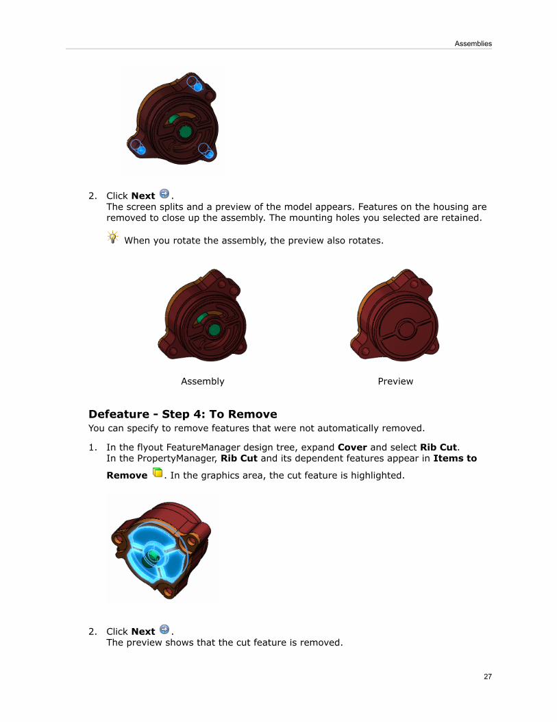
2. Click Next .The screen splits and a preview of the model appears. Features on the housing areremoved to close up the assembly. The mounting holes you selected are retained.
When you rotate the assembly, the preview also rotates.
PreviewAssembly
Defeature - Step 4: To RemoveYou can specify to remove features that were not automatically removed.
1. In the flyout FeatureManager design tree, expand Cover and select Rib Cut.In the PropertyManager, Rib Cut and its dependent features appear in Items to
Remove . In the graphics area, the cut feature is highlighted.
2. Click Next .The preview shows that the cut feature is removed.
27
Assemblies

Defeature - Feature Removal CompleteYou can save the less-detailed model in a separate part file or publish it to 3DContentCentral. The settings you select in the PropertyManager are saved in the originalmodel.
1. Under Results, select Save the model as a separate file.
2. Click .3. In the Save As dialog box:
a) For File name, type oil pump - details removed.b) For Save as type, select Part(*.sldprt).c) Click Save.The assembly is saved as a part. The part has only one feature, Imported1 , andhas no references to the original assembly.
In the assembly, Defeature appears near the top of the FeatureManager designtree.
You can right-click Defeature , click Edit Feature , change the settings, andsave another version of the assembly, with different details removed.
4. In the part window, click Section View (Heads-Up toolbar) or View > Display> Section View.The part has no internal details.
28
Assemblies

EquationsEquation functionality is enhanced.
• You can use equations to control the suppression state of assembly components.• You can share equations and global variables among models.• You can configure global variables.
See Equations on page 101.
Interference DetectionInterference Detection has been enhanced.
Ignore Hidden BodiesYou can ignore interferences with hidden bodies.
For example, suppose that in a multibody part, you create a body for construction purposesand then hide it. In an assembly, you can choose to not show interferences between thehidden body and other components.
Click Interference Detection (Assembly toolbar) or Tools > InterferenceDetection. In the PropertyManager, under Options, select Ignore hidden bodies.
Quality and PerformanceThe quality and performance of Interference Detection have been improved. Becauseof the changes, the software might find interferences that were previously missed, resultingin changes in the number of interferences reported.
Mates
Replace Mate EntitiesReplace Mate Entities is enhanced.
• The Missing Entities popup toolbar is now available while you replace any mate entities,not just while you replace a component that includes mate entities.
29
Assemblies

• While replacing multiple mate entities, you can postpone the solving of the mates.Select Defer update so that all mates are solved together when you exit thePropertyManager, instead of solving individually each time you select a replacemententity.
Select a mate, a component, or a Mates folder and click Replace Mate Entities(Assembly toolbar).
Mates in MotionTo support more accurate motion simulations, certain mates are now solved relative toother components rather than relative to the assembly origin.
The reference components for gear mates, rack and pinion mates, and screw mates aredetected automatically. For linear/linear coupler mates, you specify the appropriatereference components in the Mate PropertyManager.
The reference component information is used in SolidWorks Motion simulations.
Rebuild ReportAssemblyXpert now provides a report of the rebuild time for the total assembly.
You must rebuild the assembly during the current session of SolidWorks beforegenerating the report.
1. Click AssemblyXpert (Assembly toolbar) or Tools > AssemblyXpert.2. In the AssemblyXpert dialog box, in the information-only row about the rebuild report,
click Show these Parts .
SpeedPakNew commands make it easier to switch between SpeedPak and parent configurations ofsubassemblies. Also, sketches now appear in SpeedPak configurations.
Switching All Subassemblies to SpeedPakDo one of the following:
• When opening an assembly, click Open (Standard toolbar) or File > Open. In theOpen dialog box, select Use SpeedPak.
• In an assembly that is already open, in the FeatureManager design tree, right-click thetop-level assembly and click Use SpeedPak.
If a subassembly's active configuration has a SpeedPak configuration, then the SpeedPakconfiguration is used.
Switching Selected Subassemblies to SpeedPakIn the FeatureManager design tree, right-click one or more subassemblies and click UseSpeedPak.
If the selected subassembly's active configuration has a SpeedPak configuration, thenthe SpeedPak configuration is used.
30
Assemblies

Switching from SpeedPak to Parent ConfigurationsIn the FeatureManager design tree, right-click the top-level assembly or one or moreselected subassemblies and click Set SpeedPak to Parent.
The subassemblies switch from the SpeedPak configuration to the SpeedPak's parentconfiguration.
Sketches in SpeedPak ConfigurationsUnabsorbed sketches are included in SpeedPak configurations. You can suppress unneededsketches to avoid having them affect performance of the SpeedPak configuration. As inany assembly, you suppress and unsuppress sketches by right-clicking them in theFeatureManager design tree and selecting Suppress or Unsuppress .
31
Assemblies

6CircuitWorks
Available in SolidWorks® Premium.
This chapter includes the following topics:
• User-Defined Coordinates for Component Orientation• Interface Improvements• Workflow Improvements• Comparing Boards• Export to PADS PowerPCB Format
User-Defined Coordinates for Component OrientationYou can add a SolidWorks® user-defined coordinate system to a component that is notmodeled with the SolidWorks origin. You might obtain such components from amanufacturer website or from other CAD systems.
CircuitWorks™ assigns the user-defined coordinate system as the ECAD origin when youexport the assembly into CircuitWorks.
If you insert components without a user-defined coordinate system into aCircuitWorks assembly, CircuitWorks assigns SolidWorks origin as the ECAD origin.
To add your own coordinates to a component, see SolidWorks Help: Coordinate System.
When you name the user-defined coordinate system CWX before inserting the componentin the CircuitWorks Library, CircuitWorks assigns the user-defined coordinate system asthe ECAD origin and correctly positions the components when you insert them into acircuit board assembly.
CircuitWorks interprets the positive Z-direction of a user-defined coordinate systemas perpendicular to a circuit board assembly. The XY plane represents the boardsurface, and the X- and Y- directions control the angle at which the component isinserted into the assembly.
To assign a name other than CWX to the user-defined coordinate system representingthe ECAD origin, click CircuitWorks > CircuitWorks Options, select SolidWorksExport, and modify the Import and export components relative to thiscoordinate system option.
32

Example: LED Orientation With and Without Coordinates DefinedThe coordinates of an externally manufactured LED set the Z-direction parallel to thebase of the LED.
You add the LED to the CircuitWorks Library without defining a coordinate system namedCWX. When you insert the LED components into the board assembly after building it inCircuitWorks, the LEDs are horizontal.
Before adding the component to the CircuitWorks Library, add a coordinate systemnamed CWX to the LED component in SolidWorks.
33
CircuitWorks

The LEDs are properly oriented when you insert them into the board assembly.
Interface ImprovementsThe CircuitWorks library is enhanced.
Improvements to menus, options, and the library display include:
• Commands to import and export library data are grouped more logically on the Toolsmenu.
• The Add Parts from Folder function has been renamed Add Multiple Componentsand moved to the File menu. The Add Multiple Components wizard assists you inadding SolidWorks models to the CircuitWorks library.
For more information, see SolidWorks Help: Adding Multiple Components to the Library.• The option Check component library data for errors highlights any missingSolidWorks components in the component tree (rather than simply removing them asin previous releases). You can then remove or repair them.
• Components managed through SolidWorks Workgroup PDM or SolidWorks EnterprisePDM are marked with this icon .
Workflow ImprovementsNew options improve the CircuitWorks workflow.
• You can now save library data to a database for backup or data migration.
To save library data to a database:
1. Click Tools > Export Data > To Database.2. Select a database file name and location and click Save.
• CircuitWorks offers to overwrite zero-height components in the library if it laterencounters the same component with a defined height. You can set the Overwriteany existing 2D models in the Library with 3D model option to apply this actionautomatically.
• When you set the Add components to the librarywhen exporting from SolidWorksoption, CircuitWorks adds records to the library for any new component it encounterswhen exporting a SolidWorks assembly to CircuitWorks.
34
CircuitWorks

Comparing BoardsYou can use the Compare command to identify differences between boards (their shape,for example). In previous releases, only the components on the board were compared.
When differences are identified, you can choose whether to replace the board or selectedcomponents in the SolidWorks assembly.
Open two boards in CircuitWorks and click Tools > Compare .
Export to PADS PowerPCB FormatYou can export Circuitworks data to the PADS PowerPCB 2007 (*.asc) format.
In CircuitWorks, click File > Save As and select PowerPCB 2007 File (*asc).
35
CircuitWorks

7Configurations
This chapter includes the following topics:
• Configuration Publisher• Modify Configurations• Parameters• SpeedPak
Configuration Publisher
3D ContentCentralThe Configuration Publisher has new capabilities for 3D ContentCentral suppliers.
Part NumbersA part number can be displayed with your model on 3D ContentCentral. Your customerscan search for the model by part number.
To include a part number with the model:
1. In the design table of the model, create a column with the header $PARTNUMBER.2. Under $PARTNUMBER:
• For single-row design tables, use Microsoft Excel functions such as CONCATENATEto make the value of the cell reflect the model's part number based on values inother columns.
• For multiple-row design tables, enter a part number for each configuration bytyping or using Microsoft Excel functions.
3. In the Configuration Publisher, add controls, rules, and values.On the 3DCC Preview tab, Supplier part number displays the part number of theselected configuration. As you change selections, the part number updates to reflectthe current selections.
4. Click Upload to 3D ContentCentral and click Yes to save the model.The software generates a list of part numbers and stores it within the model in aformat that is accessible to the 3D ContentCentral software.
• For single-configuration models, a part number is generated for each possibleconfiguration, based on the rules and values you defined in the ConfigurationPublisher.
• For multiple-configuration models, the list contains the part numbers you enteredfor each configuration in the design table.
On 3D ContentCentral:
36

• On the Configure & Download page, the part number appears at the bottom of theConfigure area and updates as you change selections.
• You can search for the model by part number or partial part number.
Model TestsYou can test the health of models before uploading them to 3D ContentCentral.
A sample of possible configurations is tested. Results are reported in a log file that liststhe configurations that were tested and whether they rebuilt successfully.
To test a model before uploading it:
1. In the Configuration Publisher, on the 3DCC Preview tab, click Test.2. In the Configuration Tester dialog box, specify the sample size and where to store the
log file, and click Begin Test.
The dialog box reports the percentage of the samples that succeeded. You can view thelog file for more details.
Parent/Child RelationshipsThe Configuration Publisher offers more flexibility when defining data parents for controls.
You can define parents explicitly, and multiple parents are allowed. You no longerautomatically inherit grandparents (that is, the parents of controls which you have specifiedas parents).
You must have at least two controls already defined. Then you can add multiple dataparents to the third or later controls.
In the Configuration Publisher, under Data, one Parent field is initially visible. To add
others, click Add Parent .
Modify ConfigurationsThe Modify Configurations dialog box has been enhanced.
• The All Parameters option has been moved from the table view drop-down list to a
separate button .• Linked dimensions are grouped in a column labeled Linked Dimension instead ofappearing in columns for individual features. Each linked dimension appears in the listonly once, even if it is used in several features.
Right-click an item and select Configure dimension, Configure feature, Configurecomponent, or Configure Material.
ParametersYou can configure parameters in the following areas.
• Scale features (See Scale on page 109.)• Global variables (See Global Variables on page 106.)• Cosmetic threads (See Cosmetic Threads on page 53.)
37
Configurations

SpeedPakNew commands make it easier to switch between SpeedPak and parent configurations ofsubassemblies. Also, sketches now appear in SpeedPak configurations.
For more information, see SpeedPak on page 30.
38
Configurations

8Design Checker
Available in SolidWorks® Professional and SolidWorks Premium.
This chapter includes the following topics:
• Design Checker Standards from SolidWorks Files• File Location Check• Dimension Precision Check• Feature Positioning Check• Standard Template Check• Design Checker Report• Summary Report for Task Scheduler• Design Checker Task in Enterprise PDM
Design Checker Standards from SolidWorks FilesDesign Checker now supports the creation of standard files (*.swstd) from the followingfile formats, in addition to the *.dwg file format:
• Part (*.sldprt, *.prt)• Assembly (*.asm, *.sldasm)• Drawing (*.drw, *.slddrw)• Template (*.prtdot, *.asmdot, *.drwdot)• Drafting Standard (*.sldstd)
Click Tools > Design Checker > Check Against Existing File to specify a file for thecreation of the standard file. The program creates the standard file based on your selection,validates the active document, and displays results in the Task Pane.
File Location CheckYou can use the File Location check to verify that your document templates are locatedin the correct file path. The current document is checked against the settings in Tools >Options > System Options > File Locations.
Click File Location under Document Checks to add to the Build Checks.
The check also contains three new options for auto-correction:
• Add missing paths. During autocorrection, Design Checker adds the file paths in thepreferred values list to the list of actual values at the system level.
• Remove extra paths. During autocorrection, Design Checker removes the file pathsthat are not present in the preferred values list from the list of actual values at thesystem level.
39

• Check for order. Design Checker checks for the file path order in the actual andpreferred lists.
Dimension Precision CheckThe Dimension Precision check now includes the expected precision for dimensions,angles, and tolerances. You set the level of precision by selecting the number of digitsafter the decimal point or by setting the value. The current document is checked againstthe settings in Tools > Options > Document Properties > Dimensions.
The check also contains two new options for auto-correction:
• Modify all length dimension & tolerance precisions in document• Modify all angle dimension & tolerance precisions in document
Click Dimension Precision under Dimension Checks to add to the Build Checks.
Feature Positioning CheckThe Feature Positioning check verifies that the active document has no 2D or 3Dsketches positioned with references to fillet or chamfer edges.
Click Feature Positioning under Feature Checks to add to the Build Checks.
Standard Template CheckThe Sheet Format check is renamed to Standard Template check. This check verifiesthe sheet size properties of the drawing and the type of projection used for the views'layout.
Click Standard Template under Drawing Document Checks to add to theBuild Checks.
Design Checker ReportThe Design Checker report is now formatted for better readability. You can also save thereport as a Microsoft Word document. The report includes information for autocorrectedentities when a Design Checker task is executed from the SolidWorks Task Scheduler orSolidWorks Enterprise PDM.
The new format summarizes the failure instances according to criticality level and liststhe autocorrected parameters with their initial and corrected values.
Summary Report for Task SchedulerDesign Checker creates a summary report when run on multiple files through SolidWorksTask Scheduler.
You can access the summary report under the Status of the Design Checker task. Toview the detailed Design Checker report for a file, in the Task Scheduler summary report,select the report file path.
40
Design Checker

Design Checker Task in Enterprise PDMYou can use the new Design Checker task inside the Administration Tool of EnterprisePDM to validate selected SolidWorks documents in the vault using standards files (.swstd)created in Design Checker.
See Design Checker Validation on page 71.
41
Design Checker

9DFMXpress
This chapter includes the following topics:
• Injection Molding• Running an Injection Molding Check
Injection MoldingDFMXpress supports injection molded parts. You set the Minimum wall thickness andMaximumwall thickness parameters that DFMXpress uses to validate manufacturability.
Running an Injection Molding Check
1. With a part open, click Tools > DFMXpress.2. Click Settings.3. Under Manufacturing Process, select Injection Molding.4. Under Rule Parameters, set Minimum wall thickness and Maximum wall
thickness.5. Click Run.
The Manufacturing Process: Injection Molding report displays a list of rulespassed and rules failed.
42

10Drawings and Detailing
This chapter includes the following topics:
• Alignment Options for Dimension Palette• Auto Arrange Dimensions• Bounding Box for Sheet Metal• Cut List Properties in Drawings• Center Marks in Assembly Drawings• Cosmetic Threads• Display Scale in Orthogonal Views• Drawing Sheet Format• Dual Dimensions for Chamfers• Hide Bodies in Drawing View• Hole Tables• Merge and Unmerge Cells in Tables• Notes• Show Dimension Units• Show Model Colors in Drawings• GB Drafting Standard• ANSI Drafting Standard• 3D Drawing Views
Alignment Options for Dimension PaletteAlignment tools are available on the dimension palette when you select more than onedimension.
To display the dimension palette, select dimensions and move the pointer over the
Dimension Palette rollover button .
43

The following alignment tools are on the dimension palette.
These tools are also available on the Align toolbar.
Auto Arrange Dimensions
Automatically arranges selected dimensions. See Auto Arrange Dimensions on page49.
44
Drawings and Detailing

Space Evenly Linear/Radial
Equally spaces all dimensions, linearly or radially, between the closest and furthestselected dimensions from the part.
Linear
AfterBefore
Radial
AfterBefore
45
Drawings and Detailing

Align Collinear
Aligns dimensions horizontally, vertically, or radially.
AfterBefore
Align Stagger
Staggers linear dimensions.
AfterBefore
46
Drawings and Detailing

Top Justify Dimension Text
Top justifies linear dimension text.
AfterBefore
Bottom Justify Dimension Text
Bottom justifies linear dimension text.
AfterBefore
47
Drawings and Detailing

Left Justify Dimension Text
Left justifies linear dimension text.
AfterBefore
Right Justify Dimension Text
Right justifies linear dimension text.
AfterBefore
You can adjust the spacing between dimensions using the thumbwheel in the dimensionpalette or by manually dragging the dimensions.
48
Drawings and Detailing

• The thumbwheel appears in the dimension palette only when spacing options areavailable.
• The Dimension Spacing Value is the scaling factor for the spacing. For example,2 increases the spacing by a factor of 2, or doubles it.
Auto Arrange DimensionsThe Auto Arrange Dimensions tool positions dimensions quickly and easily.
When you use Auto Arrange Dimensions , the selected dimensions are placed asfollows:
• Spaced from smallest to largest• Aligned and centered, if possible• Spaced with the offset distances defined in Document Properties - Dimensions• Adjusted to avoid overlapping• Staggered, if necessary
Using Auto Arrange Dimensions
To use Auto Arrange Dimensions:
1. Open install_dir\samples\whatsnew\drawings\Auto_arrange.SLDDRW.
2. Box select all of the dimensions.
3. Move the pointer over the Dimension Palette rollover button to display thedimension palette.
4. Click Auto Arrange Dimensions .5. Click in the graphics area off of the dimension palette.
The dimensions are automatically arranged.
49
Drawings and Detailing

Adjusting Spacing
To adjust the horizontal spacing in the dimensions at the top of the drawing:
1. Select the horizontal dimensions at the top of the drawing and display the dimensionpalette.
2. Move the thumbwheel to the right and left to adjust the Dimension Spacing Value.
Bounding Box for Sheet MetalYou can display a bounding box that fits a flat pattern for sheet metal parts and bodies,with or without grain direction.
50
Drawings and Detailing

Bounding BoxNo Bounding Box
To display the bounding box:
1. Right-click a drawing view and click Properties.2. In the Drawing View Properties dialog box, select Display bounding box.
To set grain direction:
1. In the part, edit the Flat Pattern feature.2. Click in Grain Direction.3. Select an edge or sketch line to define the grain direction.
4. Click .
51
Drawings and Detailing

Cut List Properties in DrawingsYou can insert the cut list properties as an annotation when you insert a flat pattern viewof a sheet metal part in a drawing.
To insert the cut list properties:
1. In the graphics area, right-click the flat pattern view and click Annotations > CutList Properties.
2. Click to place the list in the graphics area.
Center Marks in Assembly DrawingsYou can insert center marks automatically in assembly drawings.
To insert center marks on holes, fillets, or slots automatically in assembly drawing views:
1. In an assembly drawing document, click Options (Standard toolbar) or Tools >Options.
2. On the Document Properties tab, click Detailing.3. Under Auto insert on view creation, select from:
• Center marks - holes - assembly• Center marks - fillets - assembly• Center marks - slots - assembly
52
Drawings and Detailing

Cosmetic ThreadsYou can configure callouts for cosmetic threads.
Cosmetic thread callouts are editable, and therefore configurable, only when Standardis set to None in the Cosmetic Thread PropertyManager.
Use one of the following methods:
Under Thread Callout, click Configurations and specify theconfigurations to which the callout applies.
PropertyManager
The column header for controlling the callout of a cosmetic threaduses this syntax:
$THREAD_CALLOUT@cosmetic_thread_feature_name
Design Table
Example:
53
Drawings and Detailing

Display Scale in Orthogonal ViewsYou can display the scale of an orthogonal view if the scale is different than the defaultdrawing scale. Previously, you could only display the scale of a detail, section, or auxiliaryview in a drawing.
To display the scale of an orthogonal view:
1. In a drawing, click Options (Standard toolbar) or Tools > Options.2. On the Document Properties tab, expand View Labels and click Orthographic.3. Select Show label if view scale differs from sheet scale.4. Click OK.
Scale Not DisplayedScale Displayed
Drawing Sheet FormatThe default location for storing drawing sheet formats is now at:
C:Documents and Settings\All Users\ApplicationData\SolidWorks\version\lang\language\sheetformat
Windows XP
C:ProgramData\SolidWorks\version\lang\language\sheetformatWindows 7
C:ProgramData\SolidWorks\version\lang\language\sheetformatWindows Vista
To change the default location, click Tools > Options > System Options > FileLocations. In Show folder for, select Sheet Formats.
Dual Dimensions for ChamfersYou can display dual units in chamfer dimensions. For example, you can display thechamfer dimensions in inches and centimeters.
To display dual dimensions for all chamfers in a drawing, click Tools > Options >Document Properties > Dimensions > Chamfer. Under Dual dimensions, selectDual dimensions display. To display units, select Show units for dual display.
54
Drawings and Detailing

To display dual dimensions for a particular chamfer, select the chamfer dimension andthen in the Dimension PropertyManager, select Dual Dimension.
Hide Bodies in Drawing ViewIn addition to hiding components in a drawing view, you can now hide a body in a drawingview.
Hiding a Body
To hide a body:
In the drawing view, right-click the body and click Show/Hide, then Hide Body.
Showing a Body
To show a body:
1. In the FeatureManager design tree or graphics area, right-click the drawing view andclick Properties.
2. In the Drawing View Properties dialog box on the Hide/Show Bodies tab, select thebody to view and press Delete.
3. Click OK.
Hole Tables
TagsYou can renumber the tags when you add or delete holes from a hole table.
Renumbering All Tags
To renumber all tags:
Right-click the hole table in the graphics area or in the FeatureManager design treeand select Renumber All Tags.
Renumbering a Series
To renumber a series:
Right-click any row in the series and select Renumber Series.In this example, hole A3 is removed and the corresponding A series is renumbered.
55
Drawings and Detailing

After renumbering seriesBefore renumbering series
Dual Unit SupportYou can display dual units in hole tables. For example, you can display the size of a holein millimeters and inches.
To display dual dimensions in hole tables, click Tools > Options > Document Properties> Tables > Hole. Under Dual dimensions, select Dual dimensions display. To displayunits, select Show units for dual display.
You can also right-click a hole table and click Show dual dimensions. When dualdimensions are displayed, you can right-click the hole table and click Show units fordual dimensions.
Merge and Unmerge Cells in TablesYou can merge and unmerge cells in a table using tools from the Table pop-up toolbar.
To merge cells:
1. Select the cells.
2. Click Merge Cells (Table pop-up toolbar).
To unmerge cells:
1. Select the cell.
2. Click Unmerge a Cell (Table pop-up toolbar).
56
Drawings and Detailing

Notes
Fit Text in Notes
The Fit Text tool is available in the PropertyManager and pop-up toolbar when youcreate notes. Previously, it was available only when you edited notes.
Pattern NotesYou can display notes in linear or circular patterns in drawings.
First create a note, then create the linear or circular pattern of the note.
1. In a drawing, click Note (Annotation toolbar) or Insert > Annotations > Note.2. In the PropertyManager, set the options for the note and place it in the drawing.
3. To create a circular note pattern, click Circular Note Pattern (Annotations toolbar),or click Insert > Annotations > Circular Note Pattern.
4. In the PropertyManager, set the options.
5. To edit the notes, double-click each note and enter the text.
57
Drawings and Detailing

Show Dimension UnitsYou can show dimension units in drawings.
1. In a drawing, click Options (Standard toolbar) or Tools > Options.2. On the Document Properties tab, click Dimensions and select Show units of
dimensions.3. Click OK.
Show Model Colors in DrawingsYou can view the model colors of a part or assembly in a drawing in HLR/HLV. Any assignedlayer overrides this setting.
To show model colors, click Tools > Options > Document Properties > Detailing.Select Use model color for HLR/HLV in drawings.
Drawing with colorsAssembly with colors
58
Drawings and Detailing
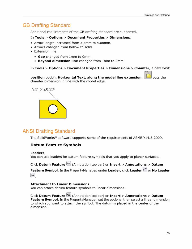
GB Drafting StandardAdditional requirements of the GB drafting standard are supported.
In Tools > Options > Document Properties > Dimensions:• Arrow length increased from 3.3mm to 4.08mm.• Arrows changed from hollow to solid.• Extension line:
• Gap changed from 1mm to 0mm.• Beyond dimension line changed from 1mm to 2mm.
In Tools > Options > Document Properties > Dimensions > Chamfer, a new Text
position option, Horizontal Text, along the model line extension, puts thechamfer dimension in line with the model edge.
ANSI Drafting StandardThe SolidWorks® software supports some of the requirements of ASME Y14.5-2009.
Datum Feature Symbols
LeadersYou can use leaders for datum feature symbols that you apply to planar surfaces.
Click Datum Feature (Annotation toolbar) or Insert > Annotations > Datum
Feature Symbol. In the PropertyManager, under Leader, click Leader or No Leader
.
Attachment to Linear DimensionsYou can attach datum feature symbols to linear dimensions.
Click Datum Feature (Annotation toolbar) or Insert > Annotations > DatumFeature Symbol. In the PropertyManager, set the options, then select a linear dimensionto which you want to attach the symbol. The datum is placed in the center of thedimension.
59
Drawings and Detailing

If you attach the symbol to a dimension that is centered between its extension lines,the symbol is placed as shown.
Geometric Tolerance Symbols
LeadersAll Over Leader is available as a new leader type.
Click Geometric Tolerance (Annotation toolbar) or Insert > Annotations >Geometric Tolerance. In the PropertyManager, under Leader, click All Over Leader
.
60
Drawings and Detailing

Material ConditionsThe following material conditions are available.
You can use the Diameter and Square symbols
when applying a Flatness tolerance.
Diameter and Square
You can use the Unequally Disposed Profile symbolin geometric tolerance symbols.
Unequally Disposed Profile
Click Geometric Tolerance (Annotation toolbar) or Insert > Annotations >Geometric Tolerance. In the Properties dialog box, set the options.
SymbolsThe following symbols are available in the symbol library.
Independency
Continuous Feature
Click Geometric Tolerance (Annotation toolbar) or Insert > Annotations >Geometric Tolerance. In the PropertyManager, under Text, click More. In the Symbolsdialog box, in Symbol library, select Modifying Symbols, then select a symbol.
3D Drawing ViewsYou can use the 3D Drawing View tool to save a 3D drawing view or to selectpre-defined view orientations.
Click 3D Drawing View (View toolbar) or View > Modify > 3D Drawing View andaccess the options in the pop-up toolbar.
The OK button has changed in functionality. When you rotate the model or set a
different view orientation from View Orientation , then click OK , the orientation
is kept. If you click Exit , you exit 3D Drawing View mode and the model returns toits original orientation.
You can save the view orientation to use it in other views. Click Save the view , typea View name, and click OK.
61
Drawings and Detailing

11DriveWorksXpress
This chapter includes the following topics:
• Task Pane Interface
Task Pane InterfaceDriveWorksXpress is now available from the SolidWorks® Task Pane. You can moveeasily between designing models in SolidWorks and automating their production inDriveWorksXpress.
62

12eDrawings
Available in SolidWorks® Professional and SolidWorks Premium.
This chapter includes the following topics:
• Display Enhancements• File Synchronization• Triad Manipulation• Filtering by Component Name• Native 64-Bit Support
Display EnhancementsThe performance of display and printing in SolidWorks® eDrawings® is significantlyimproved for some documents.
eDrawings now displays DWG files more accurately. Gradient hatches are supported, andthe handling of overlapping entities more closely matches the display order used inAutoCAD.
File SynchronizationeDrawings can now detect when the graphics data for a component may not be in syncwith a later version modified and saved within a SolidWorks assembly.
When you open a potentially outdated component, a watermark displays a warning andsuggests that you rebuild the part in SolidWorks.
To control the display of the watermark during the session, click View > ShowWarningWatermark.
Triad ManipulationYou can manipulate components of an assembly with greater control and precision.
You can use the triad tool to constrain component movement to a coordinate axis or planeand to rotate components about a coordinate axis. You can also enter values to specifyposition, translation, or rotation.
Click Tools > Move Component and select Use triad or enter values.
Filtering by Component NameYou can filter the assembly tree to show component names that contain text you specify.This feature was previously available only in eDrawings for Mac®.
63

In the Component tree , type your search text in Enter text to filter list .
Native 64-Bit SupportSolidWorks eDrawings software can now run as a native 64-bit application on a 64-bitMicrosoft® Windows® operating system, which permits larger documents to be opened.
64
eDrawings

13Enterprise PDM
This chapter includes the following topics:
• File Explorer and SolidWorks Add-in• Administration Tool• API• Installation
File Explorer and SolidWorks Add-in
Enterprise PDM MenusNew menus for the SolidWorks® Enterprise PDM client make the commands that you usemost frequently easier to find.
All commands are grouped into four Enterprise PDM menus at the top of the file viewpane.
The new menus reduce the length of the shortcut menu. However, the most frequentlyused commands are still available by right-clicking.
The commands available depend on your selection.
Click Actions to access actions you can perform such as checking files in or out.
65

Click Modify to access commands that let you make modifications, such as changing afile's state.
Click Display to control how vault information is displayed in the file view pane. TheOptions submenu lets you choose display options such as Set focus to activeconfiguration and Show bitmap for SolidWorks files. Display also lets you view aselected document's history, open it in the SolidWorks Enterprise PDM File Viewer, orview its properties.
Click Tools to access tools such as EPDM Searches, Copy Tree, the Notification Editor,the Report Generator, or the EPDM Administration tool.
66
Enterprise PDM

To access the File Explorer online help, click Get help on the Windows Explorer toolbaror select Help > SolidWorks Enterprise PDM Help on the Windows Explorer menubar.
On Windows 7 systems, Windows Explorer menus are suppressed by default. Todisplay them, click Organize > Layout and select Menu bar.
Expanded Search CapabilityYou can use new options on the History tab of the Complete Search card to search thevault based on text in file/item names and configuration/sheet names.
Administrators must use the Card Editor to add the new options to search cardscreated before SolidWorks Enterprise PDM 2011.
To access the new search options:
1. Expand (menu bar) and click Complete Search.2. On the History tab, select Look in file/item names or Look in configuration/sheet
names.3. In the Text to find in history field, type the text to search for.
4. Click Start Search (Search dialog box toolbar).
Files matching the search appear in the middle pane of the Search dialog box.
Expanded File Open CapabilitiesIn the SolidWorks Open dialog box, you can preview files by selecting them on the Containsor Where Used tabs. In SolidWorks and other applications, double-clicking a file on theContains or Where Used tabs opens the file in the application.
To use the Contains tab to preview and open files:
1. In SolidWorks, click Open (Standard toolbar) or File > Open.2. In the Open dialog box, navigate to a folder in an Enterprise PDM vault.3. Select a file that references other files (for example, an assembly) and click the Contains
tab.
67
Enterprise PDM

The referenced files are listed.4. Double-click the referenced file to open it in SolidWorks.
Updating Broken File ReferencesYou can use the Update References command to repair broken file references.
• You can repoint references to existing files in the vault.• If the referenced files are outside the vault, you can locate them, update the references,and add the files to the vault.
• You can replace existing references.
Warning messages appear when you try to check files with broken references intothe vault.
To update the references, cancel the check in and complete the following procedure:
1. Select a file with broken references.2. Click Tools > Update References.
The Update References dialog box opens, listing all references and identifying thosethat are missing.
3. If a warning indicates that a file cannot be found, click Find Files (Update Referencestoolbar).
4. In the Find Files wizard, select the folder to search, specify how the search should beperformed, and click Next.
Files that meet your search criteria are listed.5. If the Found in column indicates that there are multiple matches, expand the list and
select the file to use.6. To update a reference, in the Update column, check the box and click Finish.7. Click OK in the Update References message box.8. Click Update to save the reference paths that are shown in the Found In column to
the parent file.
Menu options in the Update References dialog box let you:
• Save the file list as a CSV file• Open the file list in Excel• Change the view of columns• Replace a selected reference• Add a file to the vault if it is found outside the vault
See SolidWorks Enterprise PDM File Explorer Help: Updating File References for moreinformation.
Saving eDrawings Markup FilesSolidWorks eDrawings markup files saved from the Save Markup dialog box areautomatically added to the vault.
To save markup files to the vault automatically, in eDrawings, click File > Save Markup.
To see the added file type in the Administration tool:
1. Click Tools > EPDM Administration to open the Administration tool.2. Expand Users, right-click your user name, and click Settings.
68
Enterprise PDM

On the Adding Files tab of the Settings dialog box, markup has been added to the listof files that are always saved to the vault.
Restoring Files from Cold StorageYou can retrieve files from cold storage for any archive server to which you have accessif your administrator has granted you permission.
You may want to retrieve files from cold storage if a design's functional specification haschanged or if you need to access an older archived design change.
You can only select one file at a time to restore. However, if a selected file such as anassembly contains references, both the parent file and the referenced files can be retreivedin one restore operation.
You can only restore files that were removed from the vault by moving archive filesto a folder outside the archive. If your administrator set up cold storage to deletearchive files, you cannot restore them.
To restore a single file from cold storage:
1. Select a file and click Actions > Get Version.2. In the submenu, expand Versions in Cold Storage and select the cold stored version
to use.3. In the Get from Cold Storage dialog box, click Restore.
The file is restored to the folder containing the non-cold stored versions.
The restored file's history contains a comment that the file was restored from coldstorage, including the restoration date and the name of the user performing the restore.
See SolidWorks Enterprise PDM File Explorer Help: Restoring Files from Cold Storage.
Creating SubmenusThe Enterprise PDM API now supports submenus.
You can use submenu support to organize items you create in File Explorer, such asSearch Favorites.
To create a submenu for your favorite searches:
1. Click Search (Enterprise PDM menu bar).2. In the SolidWorks Enterprise PDM Search dialog box, select the search type to use.3. Add search criteria to define the search.
4. Click Add to Favorites (Search dialog box toolbar).5. In the Add to Favorites dialog box, for Favorite name, type
submenu_name\favorite_name, select users who can see the favorite, and click OK.
When you view the Search menus, the new favorite will be listed in the submenu:
69
Enterprise PDM

Administration Tool
Collecting Support InformationYou can run the Collect Support Information wizard to collect information about a vault.The wizard creates a single package that you can send to technical support.
You must be logged in as the Admin user to run the wizard.
The Collect Support Information wizard lets you:
• Specify logs and settings to collect.
Options include archive server, Enterprise PDM client, and local event logs, registryand environment information, database statistics, version numbers of all installedEnterprise PDM .exe and .dll files, and all installed add-in packages.
• Select folders and files to include in the support package.
The .zip file created by the wizard maintains the archive server folder structure if youinclude archives.
• Create a backup of the SQL database.
The backup is not added to the package. You must provide the backup manuallyto technical support.
• Include special instructions or problem descriptions.
This input is saved as AdditionalInformation.txt in the package.
• Specify the location where the support information package is saved.
See SolidWorks Enterprise PDM Administration Tool Help: Vaults > Collecting SupportInformation.
Group Import from Active DirectoryIf you have defined the Archive server login type asWindows login, you can now importgroups, group memberships, and email addresses from Microsoft Windows ActiveDirectory®.
Importing groups from Active Directory lets you quickly set up the Enterprise PDMenvironment to be the same as the environment throughout your organization.
You can import Active Directory groups:
• When you add or edit a group• When you add a new user
70
Enterprise PDM

New users are added to Enterprise PDM groups with the names they have in the ActiveDirectory groups.
See SolidWorks Enterprise PDM Administration Tool Help: Importing Active DirectoryUsers into Groups.
3DVIA Composer File Format SupportSolidWorks Enterprise PDM now recognizes the 3DVIA Composer file formats .smg and.smgxml.
Users can preview embedded 3DVIA Composer files if the 3DVIA Composer Player isinstalled. As with other previews, you can use the 3DVIA Composer Player tools tomanipulate the model.
The 3DVIA Composer data card, which is installed when you create a vault using theDefault setup, lets users view file information.
The 3DVIA Composer Player is available as a free download fromhttp://www.solidworks.com/sw/support/downloads.htm, on the 3DVIA Composertab.
Design Checker ValidationYou can use the new Design Checker task to validate selected SolidWorks documentsin the vault using standards (.swstd) files created in the SolidWorks Design Checkeradd-in.
SolidWorks Design Checker verifies design elements such as dimensioning standards,fonts, materials, and sketches to ensure that SolidWorks documents meet pre-defineddesign criteria. By using auto-correct, you can modify the documents you check to meetthe design standards.
You configure the Design Checker task in the Administration tool to specify the computerthe task is run on, who has permissions to run the task, and notifications. You can alsoset up design checks to be performed during workflow transitions by specifying that theDesign Checker task is performed as a transition action.
You can initiate the Design Checker task:
71
Enterprise PDM

• For selected files in File Explorer• From the Add Task button of the Task List dialog box in the Administration tool• By changing a file's workflow state
When the task runs, you complete the Design Checker card to specify the standards fileto use, whether to auto-correct failed checks, and where to store reports and logs.
• Reports list the criteria used to evaluate the document and show failed checks.• Log files list the selections made when the task is run and the results of task execution,such as success or failure checking files out and in.
After a design check, the Design Checker status appear on the document's data card.
Configuring the Design Checker TaskYou configure the Design Checker task from the Tasks node of the Administration tool.
1. Expand Tasks and double-click Design Checker.On the Add-in screen, the Design Checker card is selected as the input card.
2. Select the user whose permissions are used when the task is run.3. In the left pane, click Execution Method and select how the task is initiated and the
computer on which the task is run.4. Click Menu Command and specify whether and how the command appears to users
in File Explorer.5. Click Permissions and select users and groups that are allowed to initiate the task.6. Click Success Notification and Error Notification to create notification messages
and select users and groups to be notified.
Running the Design Checker TaskYou can run the Design Checker task in File Explorer or from the Administration tool.
To initiate the task in File Explorer:
1. Select the files to check.2. Click Actions > Tasks > Design Checker.
To initiate the task in the Administration tool:
1. Click Tasks > Task List.2. In the Task List dialog box, click Add Task.3. In the Add Task dialog box, select Design Checker.4. Use the Select Files and Folders for Design Checker dialog box to select the files to
check, then click OK.
In both File Explorer and the Administration tool, when the task runs, the Design Checkertemplate card displays to let you specify:
• The .swstd file to use.
The standards file must be checked in to the vault.• Whether to auto correct failed checks.• Where reports and logs generated by the Design Checker task are saved.
Aliases in Card ListsA new Text with Alias card list data type lets you add aliases when you create card liststo display variable values in data cards. Aliases let you truncate values for display and
72
Enterprise PDM

use in input formulas. If you have existing lists of associated variable values and aliasesin spreadsheets or other documents, you can copy and paste them to easily create cardlists with aliases.
To create an alias list:
1. Right-click Lists (for cards) and click Add New.2. In the dialog box, type the List name and select Text with Alias as the Data type.3. In the Data list, for Displayed Value, type the value.4. For Alias, type the alias to use for the displayed value when the list is used.
To use existing lists of paired display values and aliases from spreadsheets, CSV files, orWord tables:
1. Open the source document and copy the values.2. In the card list, right-click under Displayed Value or Alias and click Paste.
To use an alias list in a data card:
1. Open the card in the Card Editor.2. Add one of the following controls:
• Listbox• Droplist• Combobox• Combolist
3. Under Items, select Special value.4. Select the alias list to use.
See SolidWorks Enterprise PDM Administration Help: Using Aliases in Card Lists.
Arithmetic and String Functions in Input FormulasYou can now add arithmetic and string functions to input formulas for data card editboxes. The arithmetic and string functions are available as input formula selection choicesthat are organized on a flyout menu. For easier access, variables have been reorganizedon a second flyout menu.
To add arithmetic and string functions to an input formula:
1. Open or create a data card in the Card Editor.2. Add an Edit control.
3. Under Input formula, to the right of the field, click .4. Select Variables to display a list of variables that you can use in the formula.
For easier access, the variables list is now divided into alphabetically-arranged sublists.
Select the variable to add.
73
Enterprise PDM

5. Select Functions to display a list of arithmetic and string functions to use.
Select the function to add.6. Save the modified card.
See SolidWorks Enterprise PDM Administration Help: Input Formula Functions.
Exported Workflow LinksWhen you export workflows as .cex files and then import them into a vault, EnterprisePDM maintains any links between workflows.
Workflow links are only maintained in .cex files when you export a workflow fromSolidWorks Enterprise PDM 2011 or higher.
To see this functionality:
1. In an Enterprise PDM archive, create vaults A and B.2. In vault A, create two workflows.3. Right-click in the first workflow, and select New Workflow Link.4. Select the second workflow as the workflow to link to.5. Save the workflows.6. Export both workflows to a .cex file.7. Import the .cex file into vault B.8. View the workflows in the Workflow editor.
The workflow link is maintained.
Associating Drawing Types with File TypesYou can improve performance by modifying file type properties to specify the types ofdrawings that are checked for references when you check specific files out or in. Thereference check determines if a drawing is a sub-parent of the file you are checking outor in.
This example describes how to specify the drawing types to check for references to.sldprt files:
1. Expand File Types.2. Double-click sldprt.
74
Enterprise PDM

3. In the File Type Properties dialog box, under This file can have drawing nodes withthe following extensions, specify the file types to be checked for references.
The file type slddrw is listed by default.
To add the file type drw, type a comma (,) and type drw, so that the field readsslddrw,drw.
Do not include periods (.)
4. Click OK.
When you check a .sldprt file out or in, Enterprise PDM looks for references to the filein all files of type slddrw and drw.
In the Check Out or Check In dialog box, drawings that are sub-parents to the .sldprtfile appear in blue above the .sldprt file so you can choose to check them out or in.
This functionality replaces two options on the File Type Properties dialog box inprevious versions of Enterprise PDM:
• Do not show "sub-parents" for this file type• Show this file type as a "sub-parent" (drawing)
APIFor information on using the Enterprise PDM API, see the SolidWorks Enterprise PDMProgrammer's Reference Guide. To access the guide, right-click Add-ins and clickProgrammer's Reference Guide.
Adding Commands to SubmenusYou can now structure add-in commands so that they appear in submenus.
You can structure cascading menus by adding backslashes to menu strings.
You do not need to do this programmatically.
For example, when you configure a task, you can make the task command appear tousers in a Tasks submenu by writing the menu command with a backslash.
In the task's Properties wizard, on the Menu Command screen, for Menu command,type Tasks\command_name. In File Explorer, users see:
Using an Add-in to Define Item Explorer Menu CommandsYou can define menu commands to be used in Item Explorer.
You can add commands to:
• Shortcut menus for files, items, and folders• The Item Explorer Tools menu
75
Enterprise PDM

• The Item Explorer toolbar
Updating the BOM Quantity Using the APIYou can now update the BOM quantity using the API without having a pre-defined BOMview.
Installation
SQL-DMO DriversIt is no longer necessary to install SQL-DMO drivers when deploying Enterprise PDMclients using an administrative installation image. Enterprise PDM components nowcommunicate with SQL Server 2008 or SQL Server 2005 using ODBC.
76
Enterprise PDM

14Flow Simulation
Two new modules, Electronic Cooling and HVAC Design, enhance Flow Simulation by helpingyou quickly solve specific industry problems.
These modules are available in the Flow Simulation CommandManager or on the FlowSimulation menu.
See Flow Simulation Help and Flow Simulation Online Tutorial: Electronic Components.
This chapter includes the following topics:
• Electronic Cooling Module• HVAC Design
Electronic Cooling ModuleThe electronic cooling module provides accurate thermal analysis of printed circuit boards(PCBs) and enclosure designs based on more realistic modeling of individual componentsand PCBs.
These factors improve the accuracy of the thermal modeling:
• The engineering database now contains more materials and components, and a PCBgenerator, for the precise thermal modeling of a multilayer PCB.
• The module accounts for the effects of Joule heating.• You can choose to represent geometry as a two-resistor model.
HVAC DesignThe HVAC module evaluates the impact of air quality and temperature on products orpeople. For example, the module can analyze a vehicle's air conditioning unit, a serverroom's cooling system, or a building's ability to clear smoke. SThe inclusion of buildingmaterials and the calculation of materials that are semitransparent to radiation, such asglass, make the thermal simulation of buildings and most enclosures easier and moreaccurate.
77

78
Flow Simulation

15Import/Export
This chapter includes the following topics:
• Exporting .IFC Files• DXF DWG Import Wizard• Exporting Sheet Metal Parts to DXF or DWG Files
Exporting .IFC FilesYou can export SolidWorks® models to the Industry Foundation Classes .ifc files format.
To export SolidWorks models as .ifc files:
1. Click File > Save As.2. For Save as type, select IFC 2x3.3. Navigate to the correct folder and enter a file name.4. Click Options, select the OmniClass
™and units, and click OK.
5. Click Save.
For more information, see SolidWorks Help: .IFC Files.
DXF DWG Import Wizard
Importing Layers from .DWG or .DXF FilesWhen importing a .dwg or .dxf file as a 2D sketch for a part, you can create a new sketchfor each layer in the file.
1. Open a .dwg file with layers.2. In the DXF/DWG Import wizard, select Import to a new part as and 2D sketch.3. Click Next.4. Select Import each layer to a new sketch.5. Select other options and click Next or Finish.
Defining the Sketch Origin and Orientation on .DWG or .DXF ImportWhen importing a .dwg or .dxf file as a 2D sketch for a part, you can define the modelorigin and orientation.
1. Open a .dwg file.2. In the DXF/DWG Import wizard, select Import to a new part as and 2D sketch.3. Click Next.4. Select part document options and click Next.
79

5. Click Define Sketch Origin and click a point in the sketch preview to define theorigin.
6. Adjust the origin values and click Apply.7. To change the model orientation about the origin, select Rotate about the origin
and enter the angle of rotation.8. Select other options and click Finish.
Filtering Sketch Entities on .DWG or .DXF ImportWhen importing a .dwg or .dxf file as a 2D sketch for a part, you can filter out unnecessaryentities.
1. Open a .dwg file.2. In the DXF/DWG Import wizard, select Import to a new part as and 2D sketch.3. Click Next.4. Select part document options and click Next.5. In the preview, select entities to remove and click Remove Entities.
To undo this action, click Undo Remove Entities .
6. Select other options and click Finish.
Repairing Sketches After .DWG or .DXF ImportWhen importing a .dwg or .dxf file as a 2D sketch for a part, you can launch theSolidWorks Repair Sketch tool from the DXF/DWG Import Wizard to fix gap or overlaperrors after import.
1. Open a .dwg file.2. In the DXF/DWG Import wizard, select Import to a new part as and 2D sketch.3. Click Next.4. Select part document options and click Next.5. Select Run Repair Sketch.6. Select other options and click Finish.
Exporting Sheet Metal Parts to DXF or DWG Files
Exporting a Bounding BoxWhen exporting a sheet metal part as a .dxf or .dwg file, you can export the boundingbox and assign the bounding box to a specific layer.
To assign the bounding box sketch to a layer:
1. Click File > Save As.2. For file type, select .dxf or .dwg.3. Click Options.4. In the DXF/ DWG Output PropertyManager, under Entities to Export, select Bounding
box.
5. Select other options and click .6. In the SolidWorks to DXF/DWG Mapping dialog box:
80
Import/Export

Assign layers to entities.•• Map other properties.• Click OK.
Exporting Bend Line DirectionsYou can map bend line directions to specific layers when you export sheet metal modelsas .dxf or .dwg files. For example, in sheet metal parts with up and down bend directions,you can map the different bend line directions to separate layers when you export thepart.
To export and map bend line directions for a sheet metal part:
1. Click File > Save As.2. For file type, select .dxf or .dwg.3. Click Options.4. Under Custom Map SolidWorks to DXF/DWG, select Enable.5. Set other export options and click OK.6. In the DXF/ DWG Output PropertyManager, under Entities to Export, select Bend
lines.
7. Select other options and click .8. In the SolidWorks to DXF/DWG Mapping dialog box:
• Assign layers to entities.• Map other properties.• Click OK.
81
Import/Export

16Large Scale Design
Large Scale Design helps you use the tools that the SolidWorks® software offers for creatingequipment, facilities, and plants.
This chapter includes the following topics:
• Walk-through• Exporting .IFC Files• Grid System
Walk-throughYou can use theWalk-through function to explore or create a video of the 3D geometryof plants or other systems. You “see” the geometry of the system as you maneuverthrough it. You can save what you see and play it back for further study.
To activate the function, click View > Lights and Cameras > Add Walk Through.
Define motion constraints and other parameters, such as the camera height, in thePropertyManager, and click Capture Motion to open the control panel. Define your
starting point, click Record , and use the controls to maneuver through the system.
You can also use the arrow keys and the mouse to maneuver through the system. Youmay eventually find that a combination of mouse and keyboard controls allows you tomaneuver through the system most efficiently.
To use the mouse, left-click to manipulate the view.
The keyboard controls are:
82

Move forward or back, turn left or right.Arrows
Move up, down, left, or right.Shift + arrows
Turn up or down.Control + arrows
Look up, down, left, or right. Press the Altand arrow keys simultaneously.
Alt + arrows
Reset “view” direction.Home
Zoom out or in.Z, Shift + Z
Increase or decrease speed.+, -
Set speed.1 - 9
Lock to constraint.Scroll Lock
Next constraint.Page Up
Previous constraint.Page Down
Record.R
Pause.Space
Cancel.Esc
Toggle map view.M
Exporting .IFC FilesYou can export SolidWorks® models to the Industry Foundation Classes .ifc files format.
To export SolidWorks models as .ifc files:
1. Click File > Save As.2. For Save as type, select IFC 2x3.3. Navigate to the correct folder and enter a file name.
83
Large Scale Design

4. Click Options, select the OmniClass™and units, and click OK.
5. Click Save.
For more information, see SolidWorks Help: .IFC Files.
Grid SystemYou can use the Grid System tool to lay out a grid system for large structures. The gridsystem is useful when creating welded structures. The grid system is also helpful whenyou work with multiple users who use different third-party applications to make grids.Multiple users can use the grid system and work from the same baseline.
You can create a grid to help specify the location of key elements in structures. Whenyou use the Grid System tool, you create a sketch to represent the grid. You can thenspecify the number of floors for the structure and the distance between each floor. Thesketch is replicated for every floor in the structure. Balloons are attached to the grid itemsto help with orientation.
Grid system with weldments appliedGrid system sketch
Click Grid System (Features toolbar) or Insert > Reference Geometry > GridSystem.
See SolidWorks® Help: Creating a Grid System.
The graphics area can appear cluttered when the grid system creates a lot of geometryor if you create multiple grid systems. To reduce clutter, you can hide the geometry.Display options are available to help you visualize the grid structure and to ensure correctgrid inferencing.
84
Large Scale Design

To access the display options, in the FeatureManager design tree, right-click Grid Systemand click View Grid Components. In the View Grid Components dialog box, select
an item and click a display option, such as Normal To .
85
Large Scale Design

17Model Display
This chapter includes the following topics:
• DisplayManager• Appearances• Lights• Scenes• Decals• PhotoView 360• Working with Appearances and Rendering a Model
DisplayManagerThe SolidWorks® DisplayManager is the central location for managing appearances, decals,scenes, cameras, lights, and Walk Through. Use the DisplayManager to view, edit, anddelete display items applied to the current model.
On the Manager Pane, click the DisplayManager tab .
See SolidWorks Help: DisplayManager.
AppearancesAll appearance functionality, including controls previously available only in PhotoView orPhotoWorks™, is now available in SolidWorks Standard. The DisplayManager lists theappearances applied to the currently active model. You can also save custom appearancesin SolidWorks Standard.
On the DisplayManager tab, click View Appearances .
86

See SolidWorks Help: Appearances.
LightsThe DisplayManager is the central location for managing all aspects of lighting, includinglighting controls that are available only when PhotoView is added in. The DisplayManagerlists the lights applied to the currently active model. Controls for shadows and fog nowprovide a stronger integration with PhotoView. Light intensity is controlled with wattages.
Lighting controls are separate for SolidWorks and PhotoView 360.
By default, point, spot, and directional lights are on in SolidWorks.
Scene lighting is not possible in RealView, so you often need toilluminate models manually.
SolidWorks
By default, lighting is off in PhotoView.
With lights off, you can use the realistic lighting provided by scenes,which is usually sufficient for rendering. You typically need additionallighting in PhotoView to illuminate occluded spaces in the model.
PhotoView
The icons for specific lights in this image from the Scene, Lights, and Cameras pane ofthe DisplayManager have the following meanings:
On in SolidWorks
Off in PhotoView
Directional1
Off in SolidWorks
Off in PhotoView
Spot1
Off in SolidWorks
On in PhotoView
Point1
On the DisplayManager tab, click View Scenes, Lights, and Cameras .
See SolidWorks Help: Lights.
87
Model Display

ScenesScene functionality is enhanced to allow full control of the scene that is visible behind themodel. The DisplayManager lists the background and environment applied to the currentlyactive model. The new Edit Scene PropertyManager, available from the View Scene panein the DisplayManager, lets you size the floor, control the background or environment,and save custom scenes.
On the DisplayManager tab, click View Scenes, Lights, and Cameras .
Scenes are simplified and now consist of the following:
• A spherical environment based on a preset scene or image you select is mapped aroundthe model.
• A 2D background that can be a single color, a gradient of color, or an image you select.Although partially obscured by the background, elements of the environment arereflected in the model. You can also turn off the background and show the sphericalenvironment instead.
• A 2D floor on which you can see shadows and reflections. You can change the distanceof the model from the floor.
The Insert Picture functionality is removed. Background images in legacy models arediscarded and are not displayed. You can use the Edit Scene PropertyManager to add abackground image to the scene.
To save a custom scene, click Save Scene on the Advanced tab of the Edit ScenePropertyManager.
Office Space scene
88
Model Display

Rooftop scene
Warm Kitchen scene
See SolidWorks Help: Scenes.
DecalsDecals are now part of SolidWorks Standard. Use the DisplayManager to view and managedecals applied to the current model.
On the DisplayManager tab, click View Decals .
See SolidWorks Help: Decals.
89
Model Display

PhotoView 360PhotoView 360 is now the standard photorealistic rendering solution for SolidWorks.PhotoWorks is no longer supported. Rendering capabilities are the same as in previousreleases. The underlying technology has been updated to enhance the user experienceand the final results.
Available in SolidWorks® Professional and SolidWorks Premium.
Add in PhotoView 360 and select actions from the PhotoView 360 menu or from theRender Tools tab of the CommandManager.
See SolidWorks Help: Rendering with PhotoView 360.
PhotoView Integrated PreviewYou can preview a rendering of the current model within the SolidWorks graphics area.
To start the preview, with PhotoView added in, click PhotoView 360 > IntegratedPreview.
PhotoView Preview WindowThe PhotoView Preview window lets you anticipate how changes to a SolidWorks modelaffect the final rendering of the model.
With PhotoView 360 added in, click PhotoView 360 > Preview Window.
See SolidWorks Help: PhotoView Previewing Renders.
90
Model Display

MotionAnimations are rendered using PhotoView.
Right-click the Motion Study tab and click Create New Motion Study.
PhotoView Support on 64-bit ComputersNative support for the PhotoView 360 application on 64-bit platforms lets PhotoView useall available system memory.
Working with Appearances and Rendering a ModelIn this example, you use the DisplayManager, change appearances on a model, and adda decal. If you have installed SolidWorks Professional or Premium, you make furtheradjustments to lighting and scenes before completing a final render.
Learning About the DisplayManager
To start working with the model:
1. Open install_dir\samples\whatsnew\display\tractor_in_box.SLDASM.
2. In the Manager Pane, click the DisplayManager tab.
The DisplayManager catalogs the appearances ; decals ; and scenes, lights, andcameras applied to the model.
3. Under the DisplayManager tab, click View Appearances .4. In Sort order, select Hierarchy.5. Expand Face.
The black appearance is applied to faces of the box. Expand the black appearanceto see where it is applied.
Adding and Editing an AppearanceIn this section, you add an appearance to a part in the model and edit the appearance.
1. Open the box part in its own window. In the graphics area, right-click the black boxand click Open Part (Context toolbar).
91
Model Display

Why do you open the part in its own window?
• You want to change the appearance of the inside of the box only. By default, inassemblies, appearances are applied to components, overriding part appearances.You edit the part to gain more control over where to apply the appearance.
• In a subsequent step, you apply a decal. We recommend applying decals to parts,not to assemblies.
2. In the Task Pane, on the Appearances, Scenes, and Decals tab , click Appearances> Plastic > Textured.
3. In the bottom pane, Alt + double-click PW-MT11010 to apply it to the entire partand to open the Appearance PropertyManager.
4. In the PropertyManager, edit the appearance:a) On the Color/Image tab, under Color, change the color to medium grey.
b) Click Advanced.c) On the Illumination tab, set Specular Amount to 0.10 to create a matte
appearance that reflects almost no light.
d) Click .
5. Review your work:
92
Model Display

On the Appearances pane of the DisplayManager, in Sort order, select Hierarchy.a)b) Expand Parts/Assemblies and Face.
The entire part has the PW-MT11010 appearance. Because the faces are highestin the hierarchy, their appearance, black, overrides the appearance at the partlevel.
Adding a DecalIn this section, you add a decal to the part. In SolidWorks 2011, you can add decalswithout loading any add-in applications.
1. Zoom in to the small rectangular panel inside the front of the box, where you willplace the decal.
2. In the Task Pane, on the Appearances, Scenes, and Decals tab , click Decals.3. Drag the logo decal to the rectangle.
4. In the Decals PropertyManager, on the Mapping tab:a) Select Fit height to selection.
The decal adjusts to fit the rectangle.
b) Click .
93
Model Display

Changing Another Appearance on the ModelReturn to the assembly and apply an appearance to the tractor.
1. Click Window > Tractor_in_box.SLDASM. If you are prompted to rebuild themodel, click Yes.
2. Zoom in to the tractor.3. Change the appearance of the rear exhaust pipe:
a) In the Task Pane, on the Appearances, Scenes, and Decals tab , clickAppearances > Metal > Chrome.
b) Drag burnished chrome to the rightmost stack.
c) On the popup toolbar, click Assembly.
4. Press F to fit the entire assembly in the graphics area.
If you have installed SolidWorks Professional or SolidWorks Premium, then PhotoView360 is available and you can continue to the next steps.
Preparing to Render: Working with Lighting and ScenesSo far, you have performed all steps in the SolidWorks software without adding inPhotoView 360. In preparation for rendering, add in PhotoView and use the Previewwindow to anticipate the effect of further changes.
1. On the Office Products tab of the CommandManager, click PhotoView 360 to addin PhotoView.
2. Click PhotoView 360 > Preview Window. Arrange or resize the Preview windowso that you can see the graphics area.While it is open, the Preview window remains on top of the SolidWorks window.
Instead of opening a new window, you can also preview renders directly in theSolidWorks graphics area. Click PhotoView 360 > Integrated Preview.
3. The light inside the box is too dim. Adjust the lighting:
a) In the DisplayManager, click View Scenes, Lights, and Cameras .b) Expand Lights. Right-click Point2 and click On in PhotoView.
By default, lights are off in PhotoView because scene lighting is usually sufficientto illuminate the model.
The PhotoView icon next to Point2 is enabled to indicate that the point light ison in PhotoView. The Preview window updates. The image in the graphics areadoes not change because your action does not affect SolidWorks.
c) Right-click Point2 and select Edit Point Light to increase the brightness of thelight.
d) On the Basic tab, select Keep light when scene changes.
94
Model Display

e) On the PhotoView tab, under PhotoView controls, set Brightness to 0.15.
f) Click .
If you are not satisfied with the lighting provided by a scene, you can either adjustthe lights in the current scene or try a new scene. Changing the scene removesall directional, point, and spot lights unless you select Keep light when scenechanges in the PropertyManager for each light.
4. Change the scene to affect lighting and highlights.a) In the Task Pane, on the Appearances, Scenes, and Decals tab, click Scenes >
Basic Scenes.b) From the bottom pane, drag Backdrop - Studio Room into the graphics area.
The Preview window updates.
Performing a Final RenderYou are now ready to perform the final render.
1. Click PhotoView 360 > Final Render.The Render Frame dialog box opens and rendering begins.
2. Click Save Image.3. Browse to the directory, type a file name, and select the type of image to save.4. Click Save.
95
Model Display

18Mold Design
This chapter includes the following topics:
• Manual Mode for Creating Parting Surfaces
Manual Mode for Creating Parting SurfacesYou can create parting surfaces using Manual Mode, which lets you modify surfacedirection. Manual Mode lets you override the defined parting surface direction andmanually create a portion of the surface.
Select Manual Mode in the Parting Surface PropertyManager to display handles that youcan manipulate to adjust the parting surface. To further modify the surface, right-clickan inner vertex and select Start fill surface region or End fill surface region.
The first image below shows an irregular parting surface. In the second image the surfacehas been fixed.
96

97
Mold Design

19Motion Studies
Available in SolidWorks® Premium.
This chapter includes the following topics:
• Function Builder for Force and Motor Functions• User Interface Changes• Reflected Load Inertia and Reflected Load Mass• Reference Components for Linear Couplers• Motion Along a Path
Function Builder for Force and Motor FunctionsYou can use the Function Builder to define motor or force profiles from an imported dataset. You can also use the Function Builder to define a motor or force profile from amathematical expression or from interpolated functions along connected segments. Formotor profiles, you can specify time, cycle angle, or any result as the independent variable.
To open the Function Builder from a motion study, clickMotor (MotionManager toolbar)and in the PropertyManager, for Motor Type, click one of the following:
98

• Segments. Defines profile from piecewise continuous functions of time or cycle angle.• Data Points. Defines profile from an interpolated data set as a function of time, cycleangle, or motion study results.
• Expression. Defines profile as mathematical expression of time, cycle angle, or motionstudy results.
You can also access the Function Builder from the Force PropertyManager.
Some Function Builder options are not available for Animation or Basic Motionstudy types.
For more information, see SolidWorks® Help: Motor and Force Profiles.
User Interface ChangesThe Force and Motor PropertyManagers have minor user interface changes for interpolatedprofiles or profiles defined from expressions.
• The Interpolated force or motor type is now the Data Points type.• The user interface options for the Interpolated and Expression force or motor typesare no longer available in the PropertyManager.
• Selecting Data Points or Expression now launches the Function Builder.• To modify an existing Data Points or Expression motor or force type, select themotor or force type and click Edit.
For more information, see SolidWorks Help: Motor and Force Profiles.
Reflected Load Inertia and Reflected Load MassForMotion Analysis studies, you can compute and plot the reflected load mass for linearmotors and the reflected load inertia for rotary motors.
To create reflected load inertia results:
1. From a Motion Analysis study, click Results and Plots .2. For Category, select Other Quantities.3. For Subcategory, select Reflected Load Inertia
4. For the first selection component , select a constant speed rotary motor from theMotionManager tree.
5. Select Plot Results options and click .
Reference Components for Linear CouplersYou can select reference components for components mated for linearly coupled motion.
When required, select reference components when you specify linear/linear coupler matesin the Mates PropertyManager.
99
Motion Studies

For more information, see SolidWorks Help: Motion for Components Mated with LinearCouplers.
Motion Along a PathFor Motion Analysis studies, you can define a path mate motor to specify displacement,velocity, or acceleration values as a body moves along a path.
To define a path mate motor:
1. From a Motion Analysis study, click Motor .
2. For Path Mate , under Mates in the FeatureManager design tree, select a pathmate.
3. Select the motor profile.
To define the motor profile from a function or from data, click Expression, DataPoints, or Segments.
4. Select options and click .
To reverse the motor direction, for Mates/Direction, click Reverse Direction
.
100
Motion Studies

20Parts and Features
This chapter includes the following topics:
• Parts• Features• Surfaces• FeatureWorks
Parts
Defeature for PartsWith the Defeature tool, you can remove details from a part or assembly and save theresults to a new file in which the details are replaced by dumb solids (that is, solids withoutfeature definition or history). You can then share the new file without revealing all thedesign details of the model.
Click Defeature (Tools toolbar) or Tools > Defeature to access the DefeaturePropertyManager, which provides tools for manual and automatic selection of details tokeep and remove.
AfterBefore
For a step-by-step example, see Defeature for Assemblies on page 25.
Equations
Sharing Equations Among ModelsYou can share equations and global variables among models.
You export selected equations and variables from a model to an external text (.txt) file.Alternatively, you can build the text file manually using an application such as Notepad.Then you import information from the text file into other models. You can choose to link
101

models to the text file, so that changes you make in the text file update the equationsand variables in the models.Exporting EquationsIn this example, you export equations from a part to a text file.
1. Open install_dir\samples\whatsnew\parts\frontplate_01.sldprt.
2. Click Tools > Equations.The Equations dialog box lists five equations.
3. Click Export.All the equations are listed in the Equations Export dialog box. Under Active, all theequations are selected for export. Link to file is selected as well.
4. Click Save.5. In the Save As dialog box, for File name, type my_equations.6. Click Save.
The equations are saved in a text file. The text file is available to import into otherparts and assemblies. Because Link to file was selected, changes you make in thetext file are propagated to the model.
In the Equations dialog box:
• Under Active, the icon indicates equations that are linked to the external file.• At the bottom of the dialog box, Linked File displays the path to the externalfile.
7. Click OK.8. Save the part. If prompted to rebuild, click Yes.
Importing EquationsNow import the equations from the text file to another part.
1. Open install_dir\samples\whatsnew\parts\backplate_01.sldprt.
2. Click Tools > Equations.3. In the Equations dialog box, click Import.4. In the Open dialog box:
a) Select my_equations.txt.b) Select Link to file.c) Click Open.
Five equations are imported into the model.
102
Parts and Features

In the Equations dialog box:
• Under Active, the icon indicates equations that are linked to the external file.• At the bottom of the dialog box, Linked File displays the path to the externalfile.
5. Click OK.
6. Click Rebuild (Standard toolbar).The equations are applied to the model.
7. Save the part.
Suppression States of Features and ComponentsYou can use equations to control the suppression state of part features and assemblycomponents.
In the Add Equation dialog box, you use the Visual Basic IIf function to specify when tosuppress or unsuppress a feature or component.
The syntax of the Visual Basic IIf function is:
iif(expression, truepart, falsepart)
where:
• expression is the expression you want to evaluate• truepart is the value to use if expression is true• falsepart is the value to use if expression is false
Defining a Feature Suppression EquationIn this example, you suppress a hole in a plate when the length of the plate is less than40 mm.
The hole you want to suppress is part of a linear pattern, so you define an equation tosuppress or unsuppress the linear pattern feature depending on the part length.
To suppress the feature:
1. Open frontplate_01.sldprt from the previous example.
2. In the FeatureManager design tree, right-click Equations and click Add Equation.The Equations and Add Equations dialog boxes open.
3. In the FeatureManager design tree, click the linear pattern feature LPattern1.
103
Parts and Features

"LPattern1" appears in the Add Equations dialog box.
If Instant 3D is active, you need to click-pause-click LPattern1. The first clickselects the linear pattern. The second click adds it to the Add Equations dialogbox.
4. In the dialog box, complete the equation:"LPattern1" = iif ("overall length"<40, "suppressed", "unsuppressed" )
You can type the entire equation or use the following tips to enter various pieces:
• To insert global variable "overall length", expand Equations in theFeatureManager design tree and click "overall length"=100.
• To insert "suppressed" and "unsuppressed", click the suppress andunsuppress buttons in the dialog box.
5. Click OK.The new equation is added to the Equations dialog box.
6. Click OK.
Testing the Feature Suppression EquationNow decrease the length of the part to 35 mm, which triggers the suppression of thelinear pattern feature.
The length of the part (length@outline) is controlled by the global variable "overalllength", which is defined in the linked external file.
To trigger the suppression state equation:
1. Open my_equations.txt.2. For "overall length", change 100 to 35.3. Save the text file.
4. Click Rebuild (Standard toolbar).The external equations file is checked for changes and the length of the part is updatedfrom 100 to 35. Because the length is now less than 40 mm, LPattern1 is suppressed,which eliminates the second hole.
5. Edit my_equations.txt again, and change "overall length" back to 100.6. Save and close the text file.
7. Click Rebuild (Standard toolbar).The external equations file is checked for changes and the length of the part is updatedfrom 35 to 100. Because the length is now greater than 40 mm, LPattern1 isunsuppressed.
104
Parts and Features

8. Save the part.
Exporting the Feature Suppression EquationNow add the new equation to the external text file.
1. In the FeatureManager design tree, right-click Equations and click Edit Equation.2. In the dialog box, click Export.
The new equation appears at the bottom of the list.3. Click Save.4. In the Save As dialog box, select my_equations.txt and click Save. When asked to
replace the existing file, click Yes.5. Click OK.6. Open my_equations.txt.
The feature suppression equation appears in the text file.
Defining a Component Suppression EquationNow use an equation to suppress a component in an assembly.
1. Open install_dir\samples\whatsnew\parts\plate_assembly_111.sldasm. Ifprompted to rebuild, click Yes.
First, import my_equations.txt so that you can use the global variable "overalllength" in the component suppression equation.
2. Click Tools > Equations.3. In the Equations dialog box, click Import.4. In the Open dialog box:
a) Select my_equations.txt.b) Select Link to file.c) Click Open.Because the assembly does not contain all the same dimensions as the parts, warningsabout invalid equations appear.
5. Click OK to dismiss each warning.
105
Parts and Features

Two equations are imported into the model, including global variable "overalllength".
6. Click OK to close the Equations dialog box.
Now add an equation to suppress the second instance of the pin when overall lengthis less than 40 mm.
7. In the FeatureManager design tree, right-click Equations and click Add Equation.8. In the FeatureManager design tree, click pin<2>.
"pin<2>" appears in the Add Equation dialog box.9. In the dialog box, complete the equation:
"pin<2>" = iif ( "overall length"<40, "suppressed" , "unsuppressed" )
You can type the entire equation or use the following tips to enter various pieces:
• To insert global variable "overall length", expand Equations in theFeatureManager design tree and click "overall length"=100.
• To insert "suppressed" and "unsuppressed", click the suppress andunsuppress buttons in the dialog box.
10. Click OK.The new equation is added to the Equations dialog box.
11. Click OK.12. Save the assembly. In the Save Modified Documents dialog box, click Save All . If
prompted to rebuild, click Yes.
Testing the Component Suppression EquationNow decrease the overall length to 35 mm, which triggers the suppression of the linearpattern feature in the two parts and the suppression of the second instance of the pin inthe assembly.
1. In my_equations.txt, for "overall length", change 100 to 35.2. Save the text file.
3. In the assembly, click Rebuild (Standard toolbar).The length of the plates changes to 35 mm and the linear pattern is suppressed. Inthe assembly, the second instance of the pin is suppressed.
Global VariablesYou can configure global variables.
In a design table, the column header for controlling the value of a global variable usesthis syntax:
106
Parts and Features

$VALUE@global_variable_name@equations
In the table body cells, type the value for the global variable. If you leave a cell blank, itinherits the value from the configuration that was active when you opened the designtable.
Example:
Features
HelixThe PropertyManager and callouts are enhanced. Methods of defining a Variable pitchhelix have been expanded.
PropertyManager and CalloutsThe PropertyManager and callouts display more information.
• Callouts for Constant pitch cases are now displayed in the graphics area, similar tothose that already appear for Variable pitch cases.
• The callouts show all parameters, including those that are for information only (shownin gray).
• In the PropertyManager, for Variable pitch, the table now shows all parameters,including those that are inactive or for information only (shown in gray).
Variable Pitch HelixYou can define a Variable pitch helix by specifying Height and Revolution.
107
Parts and Features

Previously, only Pitch and Revolution and Height and Pitch were available for Variablepitch, and you could use Height and Revolution only when defining a Constant pitchhelix.
In a part, select a sketch that contains a circle. Click Insert > Curve > Helix/Spiral.In the PropertyManager, under Defined By, select Height and Revolution. UnderParameters, select Variable pitch. Enter values for H and Rev in the table.
RevolveMore end conditions are available when creating a revolve feature.
New end conditions include:
• Up To Vertex• Up To Surface• Offset From Surface
You can specify separate end conditions for each direction (clockwise and counter-clockwisefrom the sketch plane).
The new end conditions are available when you click the following:
• Revolved Boss/Base (Features toolbar) or Insert > Boss/Base > Revolve
• Revolved Cut (Features toolbar) or Insert > Cut > Revolve
• Revolved Surface (Surfaces toolbar) or Insert > Surface > RevolveIn the PropertyManager, under Direction1, in Revolve Type, select an end condition.Select Direction2 to specify an end condition for the second direction.
Example: For this revolved boss, the end condition is Up To Surface for Direction1 andDirection2:
108
Parts and Features

ScaleYou can configure the X, Y, and Z scale factors.
Use one of the following methods:
Under Configurations, specify the configurations to which the scalefactors apply.
PropertyManager
The column headers for controlling the X, Y, and Z factors of a scalefeature use this syntax:
$X_AXIS@scale_feature_name
Design Table
$Y_AXIS@scale_feature_name
$Z_AXIS@scale_feature_name
Example:
For uniform scaling, only $X_AXIS@scale_feature_name needsto be defined.
Surfaces
Surface Extrudes From a 2D or 3D FaceYou can create extruded surfaces from models that include 2D or 3D faces and knit theextruded surfaces to surrounding features.
109
Parts and Features

Click Insert > Surface > Extrude.
1. Select a face:
• To extrude from a 3D face, select a 3D face.• To extrude from a 2D face, press Alt + select the planar face.
2. Select the end condition.3. For 3D faces, select a plane, edge, 2D face, or sketch line to define the direction of
extrusion .
Select a plane to define an extrude direction normal to the plane.
4. To remove the faces defining the extrude from the model after extruding, click Deleteoriginal faces.
5. To create a single body from the extrude when faces are deleted, select Knit result
.
6. Set other options and click .
Surface Extrudes from Faces
You can create extruded surfaces from models that include 2D or 3D faces and knit theextruded surfaces to surrounding features.In this example, you examine a part that has two surface extrudes. Both extrudes arecreated from three contiguous faces: one planar face and two 3D faces.
110
Parts and Features

Opening the ModelFirst, you open the model and examine some components.
1. Openinstall_dir\samples\whatsnew\surfaces\multiface-surf-extrude_example.SLDPRT.
2. Notice the surface extrude features in the FeatureManager design tree.
The two extrusions into and out of the central portion of the model were created byselecting three faces, deleting the original faces, and capping one end of the extrusion.
111
Parts and Features

Viewing the Surface Extrude OptionsNext, you examine the options used to specify the surface extrude for the model.
1. Click Surface-Extrude2 and click Edit Feature .
2. To view one of the 3D faces used to create the surface extrude, select Face<1>under Faces to Extrude in the PropertyManager.
3. To view the other faces used to create the surface extrude, select each of them underFaces to Extrude in the PropertyManager.
112
Parts and Features

A 3D face defines each end portionof the extude.
A planar face defines the middleportion of the extrude.
4. To display the plane defining the direction of extrusion, click Front Plane in thePropertyManager.
Notice the extrude direction is normal to the front plane.
5. Note the selected options:
• Cap end. Seals the Direction 1 end of the extrude with a translated copy of theselected 3D face.
• Delete original faces . Deletes the faces selected under Faces to Extrude
. The 3D faces are removed from the model.
• Knit result . Knits the resulting extrude to the surface boundary where theoriginal face is deleted.
6. Close the PropertyManager.
113
Parts and Features

To examine the other surface extrude created from 3D faces, rotate the modeland repeat Steps 1 - 6 for Surface-Extrude3.
Viewing the Original Surface Before the ExtrudeNext, you suppress a surface extrude to view the surface before the extrude.
1. Click Surface-Extrude2 and select Suppress .
The three faces were created by splitting the surfaces with a Split Line feature.
2. Press Ctrl + select the three faces in the middle to view the original surface used tocreate this model.
3. Close the model without saving it.
114
Parts and Features

Capping an Extruded SurfaceYou can cap an extruded surface at one end or at both ends.
Click Insert > Surface > Extrude. To seal an end of the extrude, under Direction 1in the PropertyManager, select Cap end.
You can seal the other end of the extrude by selecting Cap end under Direction2. When you cap both ends of an extrude to define an enclosed volume, a solid iscreated automatically.
Set other options and click .
FeatureWorksAvailable in SolidWorks® Professional and SolidWorks Premium.
Bosses and Cuts RecognitionFeature recognition is enhanced and new feature types are recognized.
Interactive Recognition of Boss and Cut SweepsFeatureWorks® recognizes boss sweep and cut sweep features during interactiverecognition when two faces are selected.Boss Sweep
1. Open install_dir\samples\whatsnew\FeatureWorks\FeatureWorks-BossSweep.x_t.2. First recognize the upper boss sweep. During interactive recognition of boss sweep
features, select End Face1 and End Face 2/Support Face.
3. Then, recognize the lower boss sweep. Select End Face1 and End Face 2/SupportFace.
115
Parts and Features

In the FeatureWorks PropertyManager under Interactive Features, theBoss-Sweep feature type replaces Base-Sweep. Boss-Sweep recognizes both baseand boss sweeps.
Cut Sweep
1. Open install_dir\samples\whatsnew\FeatureWorks\FeatureWorks-CutSweep.x_t.2. Use interactive recognition and under Feature type, select Cut-Sweep.3. Select End face and then select End Face 1.
4. Select End Face 2. If necessary, rotate the model.
Interactive Recognition of Cut Revolve FeaturesFeatureWorks recognizes cut revolve features of the type known as "pencil sharpeningcuts" during interactive recognition.
1. Open install_dir\samples\whatsnew\FeatureWorks\FeatureWorks-Pencil.x_t.2. During interactive recognition of cut revolve features, select the face of the cut revolved
feature.
116
Parts and Features

Do not select the top planar face. Verify that Chain revolved faces is cleared.
Interactive and Automatic Recognition of Bosses and Cuts From Non-PlanarFacesFeatureWorks recognizes extrude features (bosses and cuts) that are created fromnon-planar faces in both interactive and automatic recognition modes.
1. Openinstall_dir\samples\whatsnew\FeatureWorks\FeatureWorks-NonPlanar_1.x_t.
2. Use automatic recognition and under Automatic Features, select Extrudes.
Previously, FeatureWorks could recognize only the highlighted boss extrude.
FeatureWorks now recognizes the original boss extrude as well as the four boss extrudescreated from the non-planar face.
The extrudes must be exact offsets from the supporting face.
1. Openinstall_dir\samples\whatsnew\FeatureWorks\FeatureWorks-NonPlanar_2.x_t.
2. Use automatic recognition and under Automatic Features, click Check all filters
.
FeatureWorks recognizes one base revolve, ten cut extrudes, nine holes, two chamfers,and 42 fillets. FeatureWorks finds two circular patterns. FeatureWorks maps all of thefeatures automatically.
117
Parts and Features

Recognized FeaturesOriginal Part
Automatic Recognition of Draft FeaturesFeatureWorks recognizes draft features during automatic recognition. Drafts werepreviously recognized only in interactive mode.
1. Open install_dir\samples\whatsnew\FeatureWorks\FeatureWorks-Draft.x_t.2. In automatic recognition mode, select Standard features. Under Automatic Features,
select Drafts and Fillets/Chamfers only.
FeatureWorks maps all of the features automatically.
Combining Like Features During Automatic Feature RecognitionAutomatic feature recognition can now combine fillets, chamfers, or holes of the samegeometry into a single feature. For example, seven fillets with the same radius arerecognized as one feature. This reduces the number of features in the FeatureManagerdesign tree and lets you group features together for better readability and smaller filesize.
1. Openinstall_dir\samples\whatsnew\FeatureWorks\FeatureWorks-CombineFeatures.x_t.
2. In automatic recognition mode, select Standard features. Under Automatic Features,select Fillets/Chamfers.
118
Parts and Features

Previously, FeatureWorks recognized 36 chamfers in this example. Now, one chamferfeature appears in the FeatureManager design tree.
To turn off the combine features functionality, click FeatureWorks Options (Featurestoolbar) or Insert > FeatureWorks > Options. On the Advanced Controls tab, underAutomatic Recognition, select or clear Combine Fillets, Combine Chamfers, orCombine Holes.
119
Parts and Features

21Routing
Available in SolidWorks® Premium.
This chapter includes the following topics:
• Routing Library Manager• Route Along Existing Geometry• Weld Gaps• Autosize• Moving and Rotating a Fitting• P&ID Import• P&ID Report• Routing Options in Isolate
Routing Library ManagerThe Routing Library Manager is a new interface that can be run without launching theSolidWorks® application. It provides access to several existing and new functions.
To open the Routing Library Manager, click Routing > Routing Tools > Routing LibraryManager. Click on a tab to open a wizard or tool. Tabs are available for the followingfunctions:
• Wizards for creating routing components, and cable/wire, covering, and electricalcomponent libraries
• The Routing File Locations tab for defining library paths• The Administration Tool for managing a database and filtering parts• The Tag Schema Manager for defining the syntax and format of tags in importedschematics
The Routing Library Manager provides the following new functionality:
• The Routing Component Wizard lets you configure additional types of components suchas o-lets and elbows, pipes, and equipment. To use the wizard, create the geometryof the part and click the Routing Component Wizard tab.
120

• You can use the Tag Schema Manager to define the syntax and format of tags inimported schematics, which allows SolidWorks to interpret the data in P&ID documents.You can define the number of fields in each tag, the name of each field, and the numberof characters in each field. You can also define the delimiter character.
• The Administration Tool lets you manage the database that is used to select SolidWorksparts when you create a design from an imported P&ID. You can add part informationfrom the Routing Component Library to the database. You can also define or changeproperty values and add new properties for parts in the database. When you use aP&ID to create a design, this database is searched for parts that correspond toinformation available in the schematic and a filtered list appears. You can select a partfrom this list.
Route Along Existing GeometryYou can create a route at a defined distance from a surface, using a pipe segment or aplanar surface or face as a reference. The distance is calculated from the outer surfaceof the pipe, unless the centerline is specified.
There are two ways to define the distance:
• Use the Smart Dimension tool to define the offset distance.• Select the route segment you want to offset and then Ctrl + select the reference object.Select Route Along in the PropertyManager and then type the distance in the Modifydialog box.
Weld GapsYou can add weld gaps to routes between pipes and fittings, using global or joint-specificoffset values.
You can define weld gaps when you start a route or at any point after you have startedit.
121
Routing

• To define when you start a route, select Use weld gaps in the Route PropertiesPropertyManager and type an offset value in the text box that appears. This valueapplies to all weld gaps in the route.
• To define after you have created a route, or to edit one or more values, right-click asegment and selectWeld Gap. Type a new value for an individual weld gap in the weldgap label, or make global changes in the Weld Gap Settings PropertyManager. You can
also click Weld Gap in the Piping toolbar and select a segment.
See SolidWorks Help: Weld Gaps
AutosizeWhen you place a part, it now resizes automatically to match the target equipment orfitting.
Autosizing also works when editing a pipe. If you drag a fitting onto a pipe, the fittingsize adjusts to match the diameter of the pipe.
The size is obtained from the face that the mate reference mates to. If the size does notmatch any available component size, +/- 5%, then an attempt is made to obtain the sizefrom a CPoint.
After you place the part you are prompted to select a part configuration. If a matchingsize is not located then you are prompted to select a size and configuration.
Moving and Rotating a FittingYou can use the triad control to rotate or move parts inserted into a route.
To display the triad every time you place a part, click Tools > Options > Routing andselect the option Use triad to position and orient components.
You can also right-click a part and select Move fitting with triad.
Click and rotate one of the triad's circles to rotate the part about its axis. Click and dragone of the arrows to move the part.
Guidelines appear after a part is moved. You can use the Auto Route command toconvert the guidelines into a route when you have finished positioning the part. You canalso right-click a guideline and select Convert Guidelines.
122
Routing

See SolidWorks Help: Positioning Parts with the Triad
P&ID ImportYou can insert inline components into a pipe route after creating it from imported P&IDdata, such as from a Solution Partner. SolidWorks identifies required components suchas tees and reducers that are not defined in the document and lets you select them froma list.
Routing guidelines display without having to first place tees, inline fittings such as valves,and reducers. You can convert these guidelines to routes as required.
P&ID ReportYou can generate reports that shows missing components or incomplete connections ina 3D model created from imported P&ID data.
To generate the report, click Report in the Piping and Instrumentation pane. The P&IDValidation Report dialog box displays.
Click Text to see a printable report. Click Tree to see the piping system tree. Symbolsand tooltips in the tree identify connections that are missing or have not been successfullycreated.
Routing Options in IsolateYou now have routing-specific actions available in the Isolate command.
Right-click the piping assembly in the FeatureManager® and select Isolate.
Make your selection in the Isolate dialog box. As an example, if you select Route onlythen the route will be isolated. If you select Route and direct references then the routeand any object it is connected to will be isolated. Other options are:
• Route and secondary references• Route bounding box• Route segments bounding box
In the image below, the Isolate command is used to isolate a route.
123
Routing

124
Routing

22Sheet Metal
This chapter includes the following topics:
• Bend Calculation Tables• Convert to Sheet Metal• Flat Patterns• K-Factor in Configurations• Mapping Bend Directions When Exporting to DXF/DWG Files• Mirroring Edge Flanges and Miter Flanges• Sheet Metal Properties• Patterns of Edge Flanges and Tab Features
Bend Calculation TablesYou can calculate the developed length of sheet metal parts using bend calculation tables.
In previous releases, you calculated the developed length with K-Factor, bend table,gauge table, bend allowance, and bend deduction methods. With bend calculation tables,you can define different angular ranges, assign equations to those ranges, and calculatethe developed length of the part.
Click any sheet metal tool where you can select a calculation method for the developedlength. In the PropertyManager, under Bend Allowance, in Bend Allowance Type,select Bend Calculation and set the options.
See SolidWorks® Help: Bend Calculation Tables.
Convert to Sheet MetalThe Convert to Sheet Metal tool is enhanced.
Gauge TablesYou can use gauge tables with the Convert to Sheet Metal tool. The sheet metalparameters (material thickness, bend radius, and bend calculation method) use the valuesstored in the gauge table unless you override them.
Click Convert to Sheet Metal (Sheet Metal toolbar) or Insert > Sheet Metal >Convert To Sheet Metal. In the PropertyManager, under Sheet Metal Gauges, selectUse gauge table and select a gauge table. You can specify the file locations for gaugetables in Tools > Options > System Options > File Locations. In Show folders for,select Sheet Metal Gauge Table.
125

Rip TypesYou can define parameters for rip edges and rip sketches created with the Convert toSheet Metal tool. Available rip types are open butt, overlap, and underlap. You can alsocontrol individual rip settings by clicking a rip callout in the graphics area. Additionally,you can set the Default overlap ratio for all rips and show or hide callouts in thegraphics area.
Click Convert to Sheet Metal (Sheet Metal toolbar) or Insert > Sheet Metal >Convert To Sheet Metal. In the PropertyManager, under Corner Defaults, select a riptype and set the options.
See SolidWorks Help: Converting a Solid Part to a Sheet Metal Part.
Keep or Consume Solid BodiesWhen using the Convert to Sheet Metal tool, you can keep the solid body to use withmultiple Convert to Sheet Metal features or specify that the entire body be consumedby the tool.
Machine with a sheet metal enclosure.
Use Convert to Sheet Metal to create thefirst sheet metal body. Keep body isselected. You want to keep the solid bodyto derive another sheet metal body fromthe same solid body.
126
Sheet Metal

Use Convert to Sheet Metal to create thesecond sheet metal body. Keep body iscleared so the solid body is consumed.
Click Convert to Sheet Metal (Sheet Metal toolbar) or Insert > Sheet Metal >Convert To Sheet Metal. In the PropertyManager, under Sheet Metal Parameters,select or clear Keep body.
Bend AllowanceYou can select the bend allowance method for the developed length calculation of thepart. In previous releases, you completed the Convert to Sheet Metal command andthen changed the bend allowance in a separate step.
Click Convert to Sheet Metal (Sheet Metal toolbar) or Insert > Sheet Metal >Convert To Sheet Metal. In the PropertyManager, under Custom Bend Allowance,select a bend allowance.
CalloutsYou can show or hide callouts for Bend Edges, Rip Edges found, and Rip Sketches.
Click Convert to Sheet Metal (Sheet Metal toolbar) or Insert > Sheet Metal >Convert To Sheet Metal. In the PropertyManager, select or clear Show callouts.
Flat PatternsImprovements to flattening sheet metal parts make flattening succeed for complex shapeswhich previously failed. These improvements also provide better flattened geometry forcertain corner treatments, lofted bends, and in some cases where cuts intersect bendregions.
You can update existing flat patterns created prior to SolidWorks 2011 to use the improvedmethod.
In the FeatureManager design tree, right-click Flat-Pattern and click Edit Feature. Inthe Flat-Pattern PropertyManager, under Parameters, select Recreate flat-pattern.
K-Factor in ConfigurationsWhen you use K-Factor as the bend allowance type in sheet metal parts, you can specifydifferent values for the K-Factor in different configurations.
127
Sheet Metal

In the FeatureManager design tree, right-click Sheet-Metal1 and click Configurefeature. In the dialog box, in Sheet-Metal1, select the variable that corresponds toK-Factor. Set the K-Factor values for each configuration.
Mapping Bend Directions When Exporting to DXF/DWG FilesYou can map bend line directions to specific layers when you export sheet metal modelsas .dxf or .dwg files. For example, in sheet metal parts with up and down bend directions,you can map the different bend line directions to separate layers when you export thepart.
See Exporting Bend Line Directions on page 81.
Mirroring Edge Flanges and Miter FlangesYou can mirror edge flanges that consist of several flanges attached to different edges.You can also mirror modified miter flanges where the flanges are shortened so thegeometry does not overlap.
Mirrored edge flangesPart with multiple edge flanges
Sheet Metal PropertiesNew properties specific to sheet metal parts are calculated and displayed in the Cut-ListProperties dialog box.
Some of the properties that are calculated are based on the bounding box, the smallestrectangle in which the flat pattern can fit. You can set a grain direction to determine thesmallest rectangle that aligns with the grain direction to fit the flat pattern. The boundingbox is represented by a sketch when you flatten the sheet metal part and is located inthe FeatureManager design tree under Flat-Pattern .
When exporting a sheet metal part as a .dxf or .dwg file, you can export the boundingbox and assign the bounding box to a specific layer.
See Exporting Sheet Metal Parts to DXF or DWG Files on page 80.
The following properties are calculated in sheet metal parts:
128
Sheet Metal

Longest side of the bounding boxBounding Box Length
Shortest side of the bounding boxBounding Box Width
Bounding box length x Bounding box widthBounding Box Area
Area of the flat pattern excluding the through cut-outsBounding Box Area-Blank
Outer perimeter of the flat pattern (blank), which isused for calculating the machine’s cutting time
Cutting Length-Outer
Sum of the perimeters of internal loops or cut-outsCutting Length-Inner
Closed cut outs (through holes) on the flat pattern,which are used for calculating the machine’s idle time
Cut Outs
Number of bends in the partBends
To view these properties, in the FeatureManager design tree, expand Cut list . Right-clicka Cut-List-Item and click Properties. The properties are updated whenever youupdate the cut list or flatten the part.
See SolidWorks Help: Sheet Metal Properties and Setting the Grain Direction for BoundingBoxes.
Patterns of Edge Flanges and Tab FeaturesYou can pattern edge flanges and tab features that have additional sheet metal featuresattached.
The patterns are supported for the same sheet metal body only. Multibody is not supported.Pattern tools include linear, circular, curve driven, sketch driven, and table driven patterns.
You cannot pattern tab features with attached jogs or sketched bends.
129
Sheet Metal

23Simulation
Available in SolidWorks® Premium.
Enhancements marked with (Professional) are available in SolidWorks Simulation Professionaland SolidWorks Simulation Premium. Enhancements marked with (Premium) are availableonly in SolidWorks Simulation Premium.
This chapter includes the following topics:
• New Simulation Studies• Interface• Shells• Beams• Connectors• Contact• Mesh• Nonlinear Studies• Results
New Simulation Studies
New 2D Simplification Study (Professional)You can simplify certain 3D models by simulating them in 2D. 2D simplification is availablefor static, nonlinear, pressure vessel design, and thermal studies. You can save analysistime by using the 2D simplification option for applicable models. 2D models require fewermesh elements and simpler contact conditions compared to their 3D counterparts.
To create a 2D simplification study:
1. Click New Study (Simulation CommandManager).2. Under Type, select Static, Nonlinear, or Thermal study.
3. Under Options, select Use 2D Simplification and click .
4. In the 2D Simplification PropertyManager, set options and click .
Types of 2D SimplificationYou can select from four types of 2D simplification options based on the geometry, materialproperties, fixtures, loads, and contact conditions.
130

Simulates thin geometries with no forces acting normal to the section plane.For the plane stress assumption, no stresses develop normal to the sectionplane. This option is available for static and nonlinear studies.
Planestress
This examples shows a bracket under distributed load.
Other examples include thin plates under pressure, turning a wrench whiletightening a bolt, and snap fit of plastic clips.
Simulates thick geometries that extend a long distance on either side of thesection plane with no forces acting normal to the section plane. For the plane
Planestrain
strain assumption, no strains develop normal to the section plane. Plane strainproblems are less common than plane stress problems. This option is notavailable for thermal studies.
This example shows a dam under water pressure.
Other examples include a tunnel under pressure and sheet rolling.
Simulates geometries with constant thermal loads along the extrusion direction.This option is available only for thermal studies.
Extruded
The figure shows an example of a long block held at a uniform temperatureand suddenly exposed to a convection environment.
131
Simulation

Simulates geometries, material properties, loads, and fixtures that aresymmetric about an axis. This example shows a nonlinear contact analysisof an o-ring.
Axisymmetric
Modeled section3D geometry
Other examples include vessels under external or internal pressure andmany problems encountered in turbine construction.
2D SectionYou create 2D sections from 3D geometries, or use planar surfaces and 2D closed sketcheson the section plane to define the bodies required for analysis. You use the 2DSimplification PropertyManager to create the section.
You can create bodies in 2D by splitting solids using a section plane.
For the plane stress example of a disk shown below, use the top plane toextract the 2D model from the 3D geometry.
SectioningSolids
132
Simulation

2D section3D model
For the axisymmetric example of a bolt-nut connection, select any planethat sections the solid and the axis of revolution.
The head of the bolt and the helical pattern of the threads are notmodeled (helical threads are not axisymmetric).
2D section3D model
You can create planar surface bodies or 2D closed sketches on the sectionplane to create 2D sections.
The example shows a three-point bend test on a plate under plane strainwith the surface bodies created on the section plane.
Usingplanarsurfaces
133
Simulation

Running the Study and Viewing Results
Setting up a 2D study is similar to setting up a 3D study. Notes on 2Dsimplification studies:
Setting up a2DSimplificationStudy
• For plane stress or plane strain assumptions, you cannot apply loadsand fixtures in a direction normal to the section plane. For theaxisymmetric assumption, you cannot apply them along thecircumferential direction.
• You need to apply fixtures, loads, and contact conditions on edgesrather than faces.
• For axisymmetric models, the applied loads are given in total values(not per radian). For plane stress and plane strain models, the appliedloads are based on a thickness unit you specify.
You can view the results of a 2D simplification analysis in 2D or 3D.ViewingResults
For plane stress or plane strain assumptions, the results are the samefor all cross sections parallel to the section plane. The results are reportedper the thickness unit you specify.
3D Results Plot2D Results Plot
134
Simulation

For the axisymmetric assumption, the results are the same for all crosssections about the axis of revolution. Results are reported in total values(not per radian).
3D Results Plot (rotated 200°)2D Results Plot
2D Simplification Analysis of a Bolt-Nut ConnectionYou perform an axisymmetric analysis on a bolt-and-nut assembly to plot the stressresults on the threads. By performing a 2D simplification analysis, you save time because2D models require fewer mesh elements and simpler contact conditions compared to 3Dmodels.
To see the model, openinstall_dir\samples\whatsnew\2dsimplification\bolt_nut.sldasm.
The bolt head and the clamped members are not modeled. To apply 2D simplification,the threads are modeled as separate rings of material and not as a continuous helix(this is a simplification, as helical threads are not axisymmetric). To model thetightening of the joint or sliding of the bolt, you still need to use a 3D model.
Creating the 2D Simplification StudyYou define a 2D simplification study from the 3D model and perform a nonlinear staticstudy.
135
Simulation

1. Click the down arrow on Study Advisor (Simulation CommandManager) andselect New Study.
2. In the PropertyManager, under Name, type bolted connection.
3. Under Type, click Nonlinear .4. Under Options, select Use 2D Simplification.
5. Click .6. In the 2D Simplification PropertyManager, under Type, select Axi-symmetric.7. For Section plane, select Plane1 from the FeatureManager design tree.8. For Axis of symmetry, select Axis1 from the FeatureManager design tree.
This is the axis about which the geometry, loads, and fixtures are symmetric.
9. Click .
Applying Material Properties and Contact SetsYou define the material properties and contact sets.
1. In the Simulation study tree, right-click the bolted connection study folder andselect Properties.
2. In the Nonlinear-Static dialog box, under Geometry nonlinearity options, selectLarge strain option.You select the Large strain option to model plasticity in the bolted connection.
3. Under Solver, select Direct Sparse and click OK.
4. Right-click Parts and select Apply Material to All .5. In the Material dialog box, for Model Type, select Plasticity- von Mises.6. Click Apply and Close.
The elastic-plastic material properties of Alloy Steel are assigned to the bolt and thenut.
7. Right-click Connections and select Contact Set . In the PropertyManager,do the following:
a) For Faces, Edges, Vertices for Set 1 , select the 2D body of the bolt.
136
Simulation

b) For Faces for Set 2 , select the 2D body of the nut.
c) Under Advanced, select Surface to surface.
8. Click .No penetration contact without friction is applied between the touching thread regionsof the bolt and the nut.
Running the AnalysisYou apply load to the top edge of the bolt shank and prevent the nut from movingvertically. You then run the bolted connection study.
1. Right-click Fixtures and select Roller/Slider.
2. In the PropertyManager, for Straight Edges for Fixture , select the edge of the
bolt and the top edge of the nut as shown. Click .
137
Simulation

3. Right-click External Loads and select Force .4. In the PropertyManager, define the load:
a) Under Force/Torque, for Faces and Shell Edges for Normal Force , selectthe edge shown by arrows in the figure.
b) Select Selected direction.
c) For Face, Edge, Plane, Axis for Direction , from the FeatureManager designtree, select Plane1.
d) For Unit , select English (IPS).
e) Under Force, select Along Plane Dir 2 and type 3000.
This is the total force acting on the circular face of the bolt shank.
f) Click .
5. Click Run (Simulation CommandManager).
Viewing the ResultsYou can view the results of a 2D analysis in 2D or 3D. For an axisymmetric analysis, theresults are the same for any cross section about the axis of revolution.
138
Simulation

1. In the Simulation study tree, open the Results folder.2. Double-click Stress (-von Mises-) to display the plot.
By default, you view the results in 2D.
3. Right-click Stress (-von Mises-) and select Show as 3D plot.
By default, the 2D section revolves by 330°. You can change the angle in theStress Plot PropertyManager under Advanced Options.
The result shows plastic deformation on the model. Among the contacting threads,the first engaged thread shows a high stress value. The values are lower for thesubsequent threads.
New Response Spectrum Analysis Study (Premium)
The new Response Spectrum Analysis study estimates the peak values of your model'sresponse based on a design spectrum specified as a base excitation.
In a response spectrum analysis, the results of a modal analysis are used in terms of aknown spectrum to calculate displacements and stresses in the model. For each mode,a response is read from a design spectrum based on the modal frequency and a givendamping ratio. All modal responses are then combined to provide an estimate of themaximum response of the structure.
139
Simulation

Relative displacement response spectrum fora particular damping ratio ξ1.
equals the maximum absolute value of therelative displacement time history responsefor each SDOF oscillator.
Natural circular frequency of vibration foreach SDOF oscillator.
You can use a response spectrum analysis rather than a time history analysis to estimatethe response of structures to random or time-dependent loading environments such asearthquakes, wind loads, ocean wave loads, jet engine thrust or rocket motor vibrations.
Mode Combination Techniques
The mode combination options for evaluating the maximum response are:
Assumes that the maximum modal responses occur at thesame time for all modes. It is the most conservative amongthe modal combination methods.
Absolute Sum
Estimates the peak response by the square root of the sumof the maximum modal responses squared.
Square Root Sum ofSquares (SRSS)
This method is based on random vibration theories. It takesinto account the cross-correlation factors between twomodes and the modal damping ratios.
Complete QuadraticCombination (CQC)
Takes the absolute value of the response for the mode thatexhibits the largest response and adds it to the SRSSresponse of the remaining modes.
Naval ResearchLaboratory (NRL)
Creating a Response Spectrum Analysis Study
1. Click Simulation > Study.
a) Under Type, select Linear Dynamic .
b) Under Options, select Response Spectrum Analysis .
140
Simulation

2. Define the frequency and response spectrum options of the study. In the Simulationstudy tree, right-click the study icon and click Properties. Select the modalcombination method to estimate the maximum response.
3. Define material for each body.
Beams and composite shells are not supported in a response spectrum study.
4. Under Connections , define contact sets and any connectors.
Bonded contact, spring and edge welds connector are supported.
5. To define fixtures, right-click Fixtures and select from the options.
6. Right-click External Loads and select Uniform Base Excitation or SelectedBase Excitation. This defines the base excitation (uniform or selected) in terms ofa given displacement, velocity, or acceleration response spectrum.
In a response spectrum analysis study, you can apply multiple response spectradefinitions for uniform or selected base excitations. In case of multiple responsespectra definitions, the total response is calculated by the square root of thesum of the squares of the individual responses.
7. Right-click Result Options and select Edit/Define.8. Mesh the model and run the study.9. Right-click Results and select the desired options.
You can view the model's maximum response values (stresses, displacements,velocities, accelerations) based on the modal combination technique you selected inStep 2.
For more information on Response Spectrum Analysis studies, see SimulationHelp: Response Spectrum Analysis.
Response Spectrum Analysis of a Circuit BoardYou perform a response spectrum analysis on a circuit board assembly. You use the designresponse spectra for horizontal components of ground motion recommended by theApplied Technology Council (ATC-3-06, Tentative Provisions, 1984). You apply the designresponse spectrum in one horizontal direction and view the results. Select the NavalResearch Laboratory mode combination method to evaluate the model's expectedmaximum response.
To see the model, openinstall_dir\samples\whatsnew\response_spectrum\circuit_board.sldasm.
141
Simulation
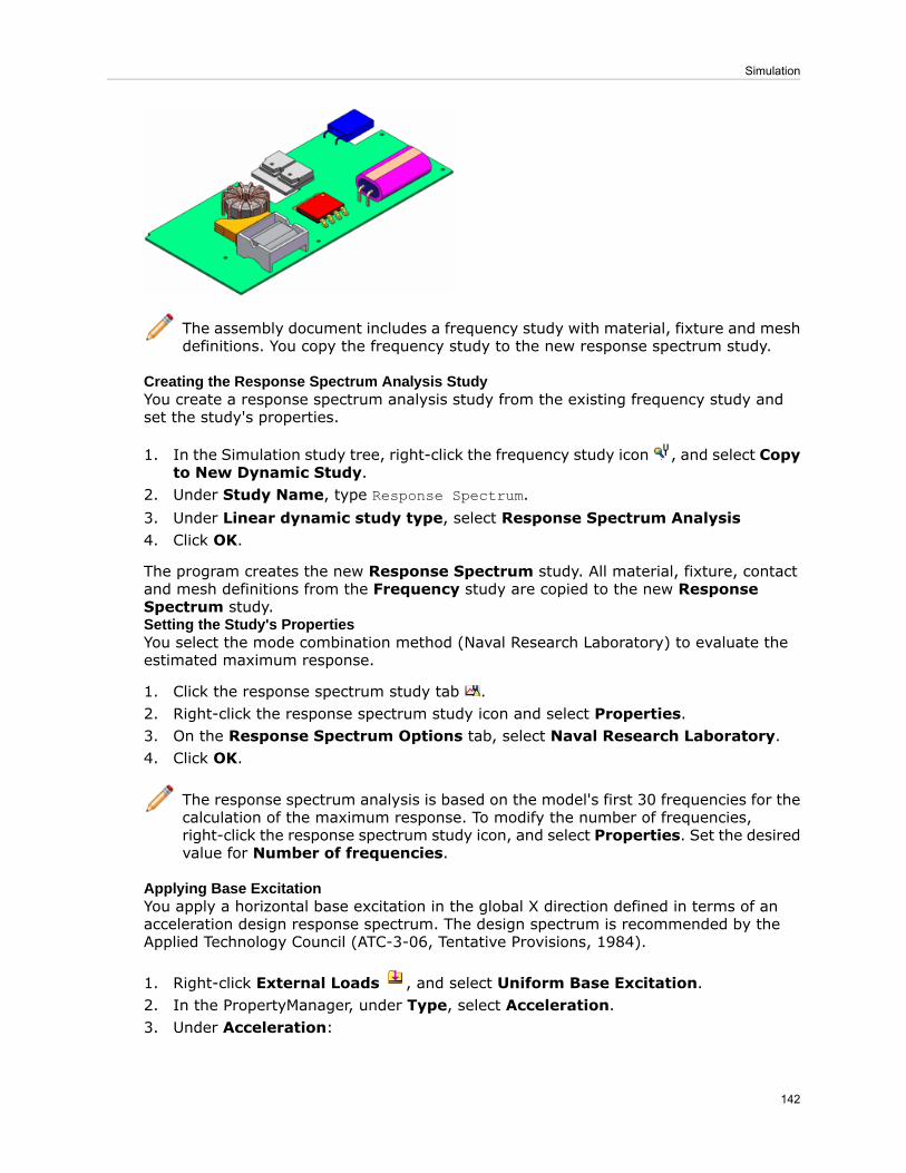
The assembly document includes a frequency study with material, fixture and meshdefinitions. You copy the frequency study to the new response spectrum study.
Creating the Response Spectrum Analysis StudyYou create a response spectrum analysis study from the existing frequency study andset the study's properties.
1. In the Simulation study tree, right-click the frequency study icon , and select Copyto New Dynamic Study.
2. Under Study Name, type Response Spectrum.3. Under Linear dynamic study type, select Response Spectrum Analysis4. Click OK.
The program creates the new Response Spectrum study. All material, fixture, contactand mesh definitions from the Frequency study are copied to the new ResponseSpectrum study.Setting the Study's PropertiesYou select the mode combination method (Naval Research Laboratory) to evaluate theestimated maximum response.
1. Click the response spectrum study tab .2. Right-click the response spectrum study icon and select Properties.3. On the Response Spectrum Options tab, select Naval Research Laboratory.4. Click OK.
The response spectrum analysis is based on the model's first 30 frequencies for thecalculation of the maximum response. To modify the number of frequencies,right-click the response spectrum study icon, and select Properties. Set the desiredvalue for Number of frequencies.
Applying Base ExcitationYou apply a horizontal base excitation in the global X direction defined in terms of anacceleration design response spectrum. The design spectrum is recommended by theApplied Technology Council (ATC-3-06, Tentative Provisions, 1984).
1. Right-click External Loads , and select Uniform Base Excitation.2. In the PropertyManager, under Type, select Acceleration.3. Under Acceleration:
142
Simulation

For Unit , select g.a)
b) Click Along Plane Dir 1 , and type 1.This excitation is applied to all locations restrained in the global X direction.
4. Under Variation with Frequency:a) Click Curve.b) Click Edit.
5. In the Frequency curve PropertyManager:a) Click Get curve to load the predefined acceleration response spectrum curve.b) In the Function Curves PropertyManager, load the curve library
install_dir\Simulation\CWLang\English\response spectra curves.cwcur.c) Expand Frequency curve and select ATC-3-06-Acceleration (g).d) For Units, select Hz.e) Click OK twice.
6. Click .
Running the Analysis and Viewing ResultsAfter you run the analysis, you can view response plots for the maximum acceleration,velocity, displacement, and stress quantities.
1. Click Run (Simulation CommandManager).2. In the Simulation study tree, right-click Results and select Define Displacement
Plot.A plot of the maximum resultant displacement appears.
3. Plot the resultant acceleration plot.
143
Simulation

Note that the maximum displacement and acceleration values occur at differentlocations of the circuit board.
You can use a different modal combination method (SRSS, Absolute Sum, orCQC) and compare the results.
Interface
Organization of BodiesEnhancements to the Simulation study tree let you apply simulation features more easily.
• You can organize bodies into folders in the Simulation study tree.• Cut lists for beams and sheet metal bodies appear in the Simulation study tree.
To create sub-folders, right-click a folder in the Simulation study tree and select CreateNew Folder. You can then drag entities into the new folder.
All options under the parent folder are available for a newly created sub-folder, forexample:
• You can assign the same material properties to the bodies in a sub-folder under the
Parts folder.
• You can drag existing pressure loads to a sub-folder under the External Loadsfolder.
Filtering the Simulation Study TreeYou can use the new Simulation-specific filter tool to filter the Simulation study tree.
Type text to filter by in the filter tool at the top of the Simulation study tree.
144
Simulation

• Filter by text-based names such as Pressure-3 or properties such as shell thickness orfixed geometry.
• Recently used searches are stored for usage in other documents.
145
Simulation

• Use Filter Graphics View to show only filtered items in the graphics area.
Display Enhancements for Simulation StudiesEnhancements to the display of parts and assemblies include:
• A body that is excluded from an analysis is hidden in the Simulation study.• When you change a body's material in a Simulation study, the material's appearanceupdates to the new material when viewing the Simulation study.
Display of Simulation SymbolsWhile editing a Simulation study, you can toggle the display of all Simulation-relatedsymbols, such as loads, fixtures, and connectors. To toggle the display of Simulationsymbols, click View > Simulation Symbols or click Hide/Show Items (Heads-UpView toolbar), and select View Simulation Symbols.
Expressions in Input FieldsYou can now type expressions in fields that allow numerical inputs.
Examples:
• To use a component of a resultant force of 50N oriented at a 30° angle to the selecteddirection, you can type 50*cos(pi/6) for Force in the Force/Torque PropertyManager.
• To reduce the parametric value of density of 7800 kg/m^3 by one-third, you can type7800/3 for User defined value in the Add Parameters dialog box.
For a list of allowed expressions, see SolidWorks Help: List of Operators and Functions.
Shells
Offsets for ShellsYou can align the mesh to the top, middle, or bottom faces of the shell. To align the meshto a reference surface, you can type an offset value.
The Shell Definition PropertyManager has the following options:
146
Simulation

Aligns the mesh with the middle surface of the shellMiddle surface
Aligns the mesh with the top surface of the shellTop surface
Aligns the mesh with the bottom surface of the shellBottom surface
Aligns the mesh to a reference surface defined by an offsetvalue that is a fraction of the total thickness. The figure showsthe meaning of the positive and negative offset values.
Specify ratio
For example, to model adjacent shells with differing thicknesses such that their bottomfaces coincide, you can create the two surfaces using the Bottom surface option.
Ply Orientation in Composites (Premium)The options for ply angles of a composite are enhanced.
To access the options, in the Shell Definition PropertyManager, under Type, selectComposite. Under Composite Options, you can do the following:
• Select a row in the Composite shell plies table.
A striped texture on the composite surface body highlights the ply angle of the selectedply. The figure shows the texture for a 45° ply angle. The white arrow shows the plydirection.
147
Simulation

• Select Ply angles relative to ply 1.
Ply angles are defined relative to its first ply. The first ply angle is always absolute. Forexample, if ply angle 1 is 45° and the absolute value of ply angle 2 is 60°, then therelative value of ply angle 2 with respect to ply angle 1 is 15°.
• Use the Planar Mapping option to define a common zero degree ply angle referencefor a group of planar shell faces or if you encounter problems with the default SurfaceMapping option.
The figure shows a face created using the surface fill operation. Thesurface mapping technique that uses the UV coordinates shows curved
InappropriatePlyOrientation stripes on the shell. You can use the planar mapping technique by
selecting the XY plane and projecting the desired ply orientation.
Planar mapping using XY planeSurface mapping
The figure shows consistent ply orientation across multiple faces withthe planar mapping option. The surface mapping creates inconsistentorientation for a 45º ply angle across the faces.
InconsistentOrientationacross Faces
Surface mappingPlanar mapping using XZ plane
Composite Stack Information (Premium)When defining a composite shell, you can now save the stack data in .csv or .txt formats.You can then reload the stack information for future use.
148
Simulation

As a best practice, you should edit the stack information in the Shell DefinitionPropertyManager. Editing the file in an external editor is not recommended.
To save or load the composite stack information:
1. In the Shell Definition PropertyManager, under Type select Composite and set thedifferent Composite Options.
2. Click Save stack to file.3. Click Load stack from file to load a saved composite stack file.
Beams
Non-uniform and Partial Loading of BeamsYou can now define non-uniform loads or loads that are defined on a part of the beam.You can specify table driven force values at different locations of the beam, or you canselect from predefined load distributions such as triangular, parabolic, or elliptical.
In the Force/Torque PropertyManager, select Nonuniform Distribution.
Select one of the following options:
Distributes the total force or moment you specify along the length of thebeam. No loads are applied at the ends of the beam. The shape of thedistribution can be parabolic, triangular, or elliptical.
Total LoadDistribution
Applies the force or moment you specify at the center of the beam. Loadsdecrease on either side of the center according to the selected distribution,
CenteredLoadDistribution and are defined per unit length. No loads are applied at the ends of the
beam.
Applies the force values at specific locations along the length of the beam.You specify the locations either as percentages or distances from one end
TableDriven
of the beam. You can select between linear and cubic interpolation schemesfor intermediate locations not specified in the table.
You can save the table as a .txt or .csv file for future use.
LoadDistribution
149
Simulation

Tapered BeamsYou can now treat tapered geometries as beams with varying cross-sectional sizes alongtheir length. Tapered geometries should have the same cross-sectional profile along theirlength to be treated as beams.
In the Simulation study tree, right-click a solid body and select Treat as Beam. A tapered
beam icon appears in the study tree, if the solid body has a taper along its length.
The figure shows a tapered I-section beam with cross sectional size that decreases linearlyalong the direction shown. The tapered beam is represented by a straight line (neutralaxis) connecting the two end joints. The lower image shows the mesh, where the beamis divided into a number of tapered beam elements represented by cylinders. Each elementconsists of two nodes having cross-sectional areas of the same shape but different sizes.The mesh and the results give you a visual indication of the taper along the beam length.
If a solid body does not qualify as a tapered beam, a warning recommends that youdo not treat the body as a tapered beam. To qualify as a tapered beam, the solidbody should maintain its cross-sectional profile along its axis, but with varying sizes.
This example shows a body with a twist along its length that does not strictly qualify asa tapered beam.
150
Simulation

Connectors
European Standard for Edge Welds (Professional)You can now use the European standard EN1993-1-8:2002- Eurocode 3 for edge weldcalculations.
To use the European standard:
1. Right-click Connections and select Edge Weld.2. In the PropertyManager, under Weld Sizing, select European Standard.
Set the properties of the weld connector:
Select the material of the attached metal component withthe lesser tensile strength value. You can also select Customto define the tensile strength value of the weld.
Material of weakerjoined part
Type the value of the tensile strength for the custom weldmaterial. For other selections, the value is populatedautomatically.
Ultimate TensileStrength
Type the correlation factor used to determine whether the resistanceof the weld is sufficient.
For correlation factors of different material grades, seeEN1993-1-8:200 - Eurocode 3 Standard, Table 4.1.
Correlation Factor
Type the partial safety factor used to determine whether theresistance of the weld is sufficient.
For correlation factors of different types of joints, seeEN1993-1-8:200 - Eurocode 3 Standard, Table 2.1.
Partial Safety Factor
Type the value of the weld size. Edge weld calculations determinewhether this size provides adequate resistance to the appliedloads.
Estimated weld size
151
Simulation

Contact
Automatic Option for Simplified BondingThe solver now selects the surface-based or node-based bonding contact based on certainperformance criteria. If the default surface-to-surface bonding slows down the solutionconsiderably, the solver switches to node-to-surface bonding automatically. The newoption for automatic bonding contact is available for Static, Frequency, Buckling, andLinear Dynamic Studies.
Right-click the Simulation study's icon and select Properties. Under Incompatiblebonding options, select Automatic.
Mesh
Mesh Enhancements• Solid and shell meshing performance has been improved because SolidWorks Simulationnow takes advantage of your computer's multi-processors for meshing surfaces.
• The default mesher is now the curvature-based mesher.• The curvature-based mesher supports the option Remesh failed parts withincompatible mesh.
• Mesh diagnostics is incorporated in the Mesh Advisor, which guides you to resolvemeshing issues like meshing failed bodies.
• You can control the mesh size of beams. Specify the total number of elements or theelement size.
In the Mesh Control PropertyManager, under Mesh Parameters, select Number ofelements or Element Size.
Nonlinear Studies
Improved Accuracy for Nonlinear fixtures (Premium)An exact method rather than an approximate penalty method is used to apply fixtures innonlinear studies. The new method avoids numerical convergence difficulties encounteredby the penalty method and improves accuracy and speed for most nonlinear studies.
The performance improvement is more prominent (up to 20% gain in analysis time) fornonlinear studies with many restraint definitions and higher mesh densities.
Results
Nonlinear Plots (Premium)You can plot elemental principal strains for nonlinear studies.
In the Strain Plot PropertyManager, select First, Second, or Third Principal Strain in
Component .
152
Simulation

Heat Power and Heat EnergyYou can more easily and accurately find out the heat power generated or dissipatedthrough selected entities for steady-state and transient thermal studies.
Right-click Results and select List Heat Power/Energy. Heat energy is available fortransient thermal studies only and for a specified time interval.
Interaction with List Result TablesWhen you highlight a row in the Pin/Bolt/Bearing or List Beam Forces dialog box, thecorresponding connector or beam is highlighted in the graphics area and Simulation studytree.
Probe Callout EnhancementsProbe callouts contain more information and can be relocated in the graphics area.
• You can move probe results to different locations in the graphics area.
153
Simulation

Before
After
• You can customize the callouts to display annotations such as ID numbers (nodenumbers), coordinates, and results-specific information like von Mises stress ortemperature. In the Probe Result PropertyManager, under Annotations, select or clearthe results-specific annotations. In this example of a thermal study, Show Value isselected and Show Node/Element Number and Show X, Y, Z Location are cleared.
154
Simulation

• When probing an envelope plot for a transient study, the solution step is listed.
Sensors for Transient StudiesYou can now define sensors to track the results of nonlinear, drop test, linear dynamics,and transient thermal studies. You can define these sensors to track values across allsteps, at a specific plot step, or at a specific mode.
In the Sensor PropertyManager, for Sensor Type , select Simulation Data. UnderProperties, for Step Criterion, select one of the following:
Tracks the Simulation data value across all steps for the entiremodel or for the selected entities and reports a single value. For
Across All Steps
example, if you select Model Max for Criterion , the sensorreports the maximum value in the model across all steps.
Tracks the Simulation data value at the specified plot step basedon the plot number you specify. You can control the number of
At Specific PlotStep
plot steps and the step interval using the Result Optionsfolder in the Simulation study tree.
This option is available only for the frequency and buckling sensors.Specifies the mode number at which the sensor tracks the result.
At Specific ModeShape
Study Reports
Report Styles and Sections
• Different report styles are available and the included sections are customized to thestudy type.
To select specific sections for a report type, click Simulation > Options. On the DefaultOptions tab, click Report and select a report style from Report formats. After selectinga report format, select or clear Report sections.
• Reports are available for all study types.
Image Capture Enhancements
You can include annotations for fixtures and loads when capturing the image for a report.
155
Simulation

• After creating a report, in the Simulation study tree, right-click Report and selectInclude Image. Set the parameters. To display the annotations, select Annotationsand select or clear features under Feature Name. You can move the callouts to different
positions. Click to add the image to the Images folder.
• To add the image to a report, add the image to the report's folder, right-click the reportin the Report folder, and select Publish.
Graphs for Material Properties
Related graphs are included along with material properties. In this example, the CurveData graph is included with the material properties.
156
Simulation

SimulationXpress Study Reports
SimulationXpress study reports are generated as Microsoft Word documents.
157
Simulation

24Sketching
This chapter includes the following topics:
• Grid System
Grid SystemYou can use the Grid System tool to lay out a grid system for large structures. The gridsystem is useful when creating welded structures. The grid system is also helpful whenyou work with multiple users who use different third-party applications to make grids.Multiple users can use the grid system and work from the same baseline.
You can create a grid to help specify the location of key elements in structures. Whenyou use the Grid System tool, you create a sketch to represent the grid. You can thenspecify the number of floors for the structure and the distance between each floor. Thesketch is replicated for every floor in the structure. Balloons are attached to the grid itemsto help with orientation.
Grid system with weldments appliedGrid system sketch
Click Grid System (Features toolbar) or Insert > Reference Geometry > GridSystem.
158

See SolidWorks® Help: Creating a Grid System.
The graphics area can appear cluttered when the grid system creates a lot of geometryor if you create multiple grid systems. To reduce clutter, you can hide the geometry.Display options are available to help you visualize the grid structure and to ensure correctgrid inferencing.
To access the display options, in the FeatureManager design tree, right-click Grid Systemand click View Grid Components. In the View Grid Components dialog box, select
an item and click a display option, such as Normal To .
159
Sketching

25Sustainability
This chapter includes the following topics:
• New Supported Regions• Sustainability Link for Custom Material
New Supported RegionsSolidWorks® Sustainability and SustainabilityXpress support these additional regions:South America, Australia, and India. You can specify the regions as Manufacturingor Transportation and Use regions.
Sustainability Link for Custom MaterialYou can perform a sustainability analysis using custom materials. This is done by linkingyour custom material to a material with similar characteristics in the default SolidWorksMaterials database. The analysis is then performed using the Sustainability characteristicsof the SolidWorks material.
To link your custom material to a similar material:
1. In the Material dialog box, in a custom materials library, select your custom material.2. In the Properties tab, in Material properties, click Select.3. In the Match Sustainability Information dialog box, select the material that is most
similar to your custom material.
Only materials with a link to the Sustainability database are listed.
4. Click OK.5. Click Apply and Close.
160

26SolidWorks Utilities
Available in SolidWorks® Professional and SolidWorks Premium.
This chapter includes the following topics:
• Symmetry Check Utility• Find/Modify/Suppress Feature Selection
Symmetry Check UtilityYou can use the Symmetry Check Utility to check component symmetry about a selectedplane, and to identify symmetric and asymmetric components in an assembly.
To run a part or assembly symmetry check with respect to a plane, select the plane in
the FeatureManager design tree and click Symmetry Check (Tools toolbar).
161

By default, after running a symmetry check on an assembly, components that aresymmetric with respect to the selected plane appear blue and asymmetric componentsare pink.
For more information, see SolidWorks® Help: Symmetry Check Utility.
Find/Modify/Suppress Feature SelectionYou can select a part feature to match when using the Find/Modify/Suppress utility.
To find, modify, or suppress part features based on properties of a selected feature, select
the feature and click Find/Modify Features (Tools toolbar).
For more information, see SolidWorks Help: Find/Modify/Suppress Feature Selection.
162
SolidWorks Utilities

27Toolbox
Available in SolidWorks® Professional and SolidWorks Premium.
This chapter includes the following topics:
• Opening Models with Referenced Toolbox Components• Gears in the GB Standard
Opening Models with Referenced Toolbox ComponentsWhen you open an assembly, SolidWorks® automatically finds references to Toolboxcomponents in your Toolbox folder, even if the assembly is created from a separateToolbox installation, for example, from outside your company. You can set this behavior,which is applied to all new SolidWorks installations by default, from a Hole Wizard/Toolboxsystem option.
To set SolidWorks to search the Toolbox folder for referenced Toolbox components:
1. Click Options (Standard toolbar).2. Click Hole Wizard/Toolbox.3. Select Make this folder the default search location for Toolbox components.
If you clear the system option, SolidWorks does not automatically find Toolboxcomponent references in the Toolbox folder.
Gears in the GB StandardToolbox administrators can include GB standards gears in Toolbox.
To include GB standard gears in Toolbox:
1. From the Windows Start menu, click All Programs > SolidWorks version >SolidWorks Tools > Toolbox Settings.
2. From the Select Hardware page, click GB, Power Transmission, and Gears.3. Select the required GB gears and clear the unnecessary ones.4. Close Toolbox Settings.
163

28Weldments
This chapter includes the following topics:
• Cut Lists• Weld Beads• Weld Support in Drawings
Cut Lists
Cut List IconsNew icons appear in the FeatureManager design tree under Cut list.
The icons are based on the type of body in the model:
• Sheet Metal• Weldment or structural members• Other bodies
Reordering and Excluding Cut List ItemsYou can reorder Cut-List-Item folders. Because the order of the Cut-List-Item foldersdrives the cut list entries, you can apply a customized order to the cut list. The reorderingpropagates to the cut lists in the part and drawing. You can also exclude Cut-List-Itemfolders from cut lists.
To reorder the Cut-List-Item folders:
• Drag and drop folders in the FeatureManager design tree.• Use the Cut-List Properties dialog box to drag and drop folders on the Cut List Summaryor Cut List Table tabs.
To exclude Cut-List-Item folders from cut lists:
• Right-click a folder in the FeatureManager design tree and click Exclude from cut list.• Use the Cut-List Properties dialog box to select Exclude from cut list on the Cut ListSummary and Cut List Table tabs.
See SolidWorks Help: Excluding Folders from Cut Lists.
You should finish modeling the part before modifying the cut list items. You maylose changes to the cut list if you change the geometry after modifying the cut list.
Weld BeadsYou can add simplified weld beads to weldment parts and assemblies, and multibodyparts.
164

Benefits of simplified weld beads:
• Uniform implementation in parts and assemblies• Compatiblity with all types of geometry, including bodies with gaps• Lightweight, simplified weld bead display• Inclusion of weld bead properties in drawings using weld tables• Smart Weld selection tool for face selection of weld bead paths• Association of weld bead symbols with the weld beads• Handles that assist in defining weld paths (lengths)• Inclusion in the Weld Folder in the FeatureManager design tree
Additionally, you can set properties for Weld Sub Folders, including:• Weld material• Weld process• Weld mass per unit length• Welding cost per unit mass• Welding time per unit length• Number of weld passes
Click Weld Bead (Weldments toolbar) or Insert > Weldments > Weld Bead. Inan assembly, click Insert > Assembly Feature > Weld Bead.
Weld Bead DisplayWeld beads are displayed as graphical representations in models. The weld beads arelightweight and do not affect performance.
Weld Beads in Assemblies
Weld BeadsYou can add simplified weld beads to assemblies.
165
Weldments

In previous versions of SolidWorks®, you added weld beads as components of theassembly. This method is no longer supported. However, you can still edit existingweld bead components.
Fillets and ChamfersIn assemblies, you can create fillets and chamfers, which are useful for weld preparation.As with other assembly features, you can propagate these features to the parts theyaffect.
Example: Adding Chamfers and Weld Beads to an AssemblyIn this example, you add chamfers to two plates to prepare them for welding. Then youadd a simplified weld bead.
Adding a Chamfer to an Assembly ComponentFirst, add a chamfer to the plate on the right.
1. Open install_dir\samples\whatsnew\assemblies\plate_assembly.sldasm.
2. Click Assembly Features (Assembly tab on the CommandManager) and click
Chamfer , or click Insert > Assembly Feature > Chamfer.3. In the PropertyManager, under Chamfer Parameters, for Edges and Faces or
Vertex , do the following to select the edge of plate01:a) Right-click the top edge between the two plates and click Select Other.
166
Weldments

b) In the dialog box, select Edge@[plate01<1>].A preview of the chamfer appears.
4. Under Chamfer Parameters:a) Select Angle distance.
b) Set Distance to 5.
c) Set Angle to 45.
Under Feature Scope, you can select Propagate feature to parts if you wantto add the chamfer to the plate's part file.
5. Click .The chamfer appears.
Adding a Chamfer to a Second ComponentNow add a chamfer to the other plate.
1. Select the edge of the plate.
167
Weldments

2. Click Assembly Features (Assembly tab on the CommandManager) and click
Chamfer .A preview of the chamfer appears.
3. In the PropertyManager, click .The chamfer appears in the second plate.
Adding a Weld BeadNow add a weld bead to the assembly.
1. Do one of the following:
• Click Weld Bead (Weldments toolbar).
• Click Assembly Features (Assembly tab on the CommandManager) and click
Weld Bead .• Click Insert > Assembly Feature > Weld Bead.
2. In the PropertyManager, under Settings:a) For Weld selection, select the faces of the two chamfers in the graphics area.
168
Weldments

b) Set Bead size to 15.
3. Click .The weld bead appears in the graphics area.
In the FeatureManager design tree, Weld Folder appears. Weld bead featuresthat have identical properties are stored together in subfolders. Weld Bead1 isthe weld you just created.
Weld Support in Drawings
Weld Symbols• In drawings, you can insert bi-directional weld symbols that are attached to weld paths.Click Insert > Model Items and under Annotations, click Weld Symbols.
• You can insert weld symbols, caterpillars, and end treatments for weld beads in specificviews. Click Insert > Model Items and under Source/Destination, click Selectedfeature for Source. Under Annotations, click Weld Symbols, Caterpillar, or EndTreatment. Move the pointer to highlight a weld path and click to place the annotation.You can also select weld bead features from the FeatureManager design tree while inthe Model Items command.
Weld TablesYou can insert weld tables in a drawing that summarize the weld bead data.
By default, weld tables include:
• Weld size• Symbol• Weld length• Weld material
169
Weldments

• Quantity
You can add other weld bead custom properties to the table such as weld cost and weldtime, and save it as a template for future use.
In a drawing view, click Weld Table (Table toolbar) or Insert > Tables > Weld
Table. In the PropertyManager, set the options and click .
170
Weldments