tw-800r-exp instruction manual (v1.20)tw-800r-exp manual v1.20 please use this operation manual...
TRANSCRIPT
Wireless Communication
TW-800R-EXP Manual V1.20
Please use this operation manual correctly on reading
well. Please keep it carefully to be able to read
immediately, when required.
Contents
■General outline ..........................................................1
■Main part and accessories ........................................1
■Safety concerns ........................................................3
■Name and function of each part ...............................4
■Installation .................................................................5
■Setting .......................................................................6
■How to use ................................................................7
■Specification ..............................................................9
■Dimensional drawing ..............................................10
■After service and Warranty ..................................... 11

TW-800-EXP
1
■General outline [TW-800R-EXP] is a product to be fixed extension unit of 3 relay output to [TW-800R].
This manual is described about only a function of extension unit. Please read [TW-800 manual] about transmitter
[TW-800T] and receiver [TW-800R] and wireless specification.
We do not make a sale only extension unit. If you want to add an extension unit with TW-800R, please inform our
sales department.
<Feature>
◆TW-800R-EXP has 4 relay output by being attached an extension unit additional to TW-800R.
It can be used 4 transmitters”TW-800T” with 1 receiver “TW-800R-EXP”.
◆The contents set up by TW-800R are reflected also in OUT2/OUT3/OUT4 of an extension unit.
◆The Pairing for extension unit is done by each pairing switch of OUT2/OUT3/OUT4.
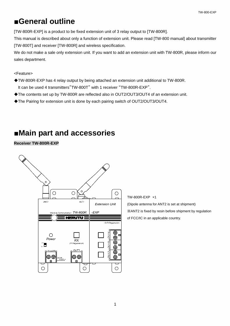
■Main part and accessories
Receiver TW-800R-EXP
TW-800R-EXP ×1
(Dipole antenna for ANT2 is set at shipment)
※ANT2 is fixed by resin before shipment by regulation
of FCC/IC in an applicable country.

TW-800-EXP
2
Option
・AC Adapter ADB24050-C (With connecting cable 1.8m)
・External antenna MB-13F (With magnet base/Coaxial cable approx. 1.5m)
*ANT2 is fixed by resin before shipment by regulation of FCC/IC in an applicable country.
Cable approx. 1.5m
Cable approx. 1.8m
Coaxial cable approx. 1.5m
Antenna approx. 22.5cm

TW-800-EXP
3
■Safety concerns
Safety concerns (Be sure to read)
To prevent human injury of user or damage in property from occurring, be sure to observe the precautions
shown below.
■ The degree in safety hazard and damage generated by the wrong usage while ignoring the descriptions is
classified by the following displays.
Using in an improper way while ignoring this pictorial symbol might cause a death or
serious human injury.
Using in an improper way while ignoring this pictorial symbol might cause a human injury
or property damage.
■ About use environment and safekeeping environment
●Because it may cause trouble and malfunction, characteristic deterioration, a fire, the electric
shock, please avoid the use at the following place and the safekeeping.
・The use at a place getting the direct rays of the sun and safekeeping
・The use at the place where a liquid and an alien substance, corrosive gas or flammable gas may
be in in a product and safekeeping
・A place and lamp soot having high moisture, dust, the use at the place with much sand and
safekeeping
・Use at the unstable place including the top of the stand which shook and the place that declined
・Use at the place with the vibration
Warning
■For handling this machine:
●In the use that extremely high reliability affecting human life is required, please do not become
the use.
Warning
■ During use, I outrun a power supply plug from an outlet, and, please ask store or us for repair because it
causes a fire, the electric shock when abnormality occurred.
●Do not use this product for the application needing the high reliability related to human lives.
●Do not use this product in a place where it is uncertain about whether or not radio waves reach.
When you use this machine, please be sure to read "cautions on safety and use" of "TW-800 operation manual"
before using it.
Warning
Caution
TW-800-EXP
4
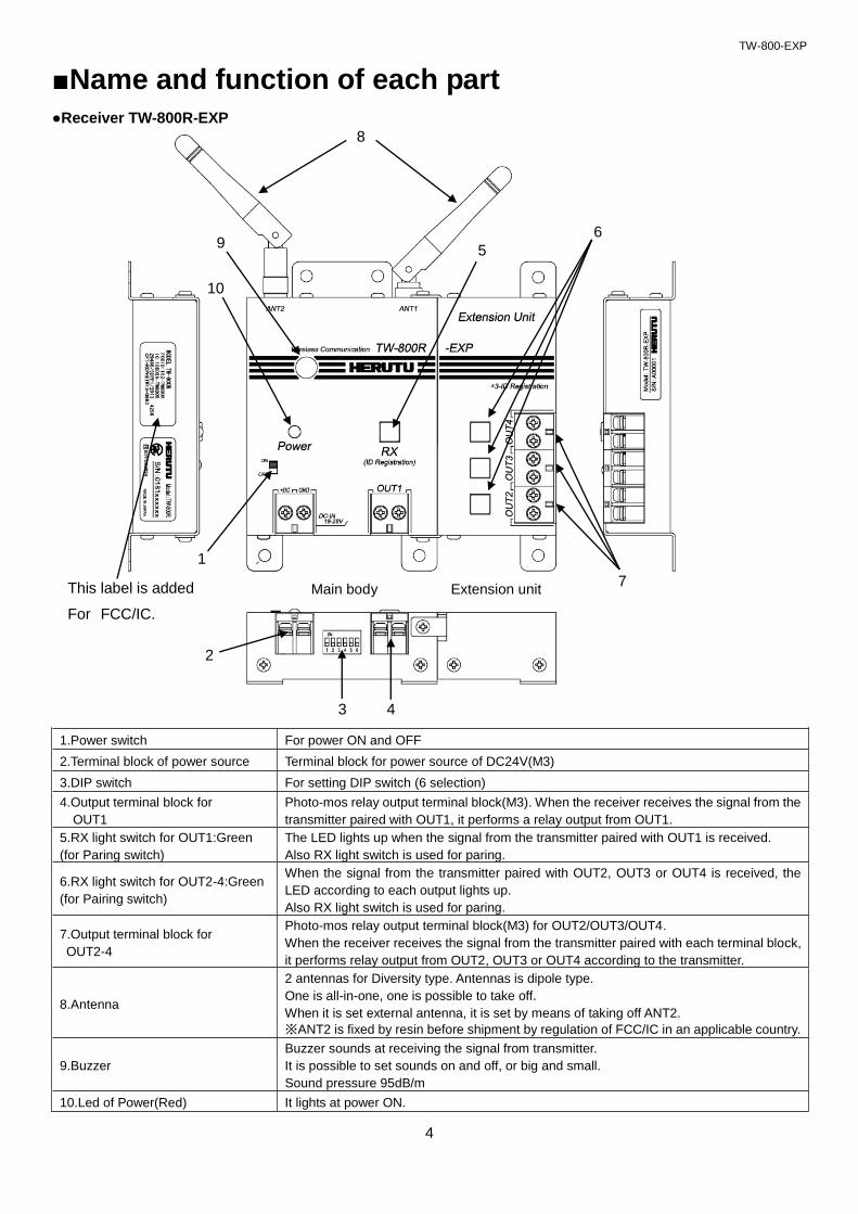
■Name and function of each part
●Receiver TW-800R-EXP
1.Power switch For power ON and OFF
2.Terminal block of power source Terminal block for power source of DC24V(M3)
3.DIP switch For setting DIP switch (6 selection)
4.Output terminal block for
OUT1
Photo-mos relay output terminal block(M3). When the receiver receives the signal from the
transmitter paired with OUT1, it performs a relay output from OUT1.
5.RX light switch for OUT1:Green
(for Paring switch)
The LED lights up when the signal from the transmitter paired with OUT1 is received.
Also RX light switch is used for paring.
6.RX light switch for OUT2-4:Green
(for Pairing switch)
When the signal from the transmitter paired with OUT2, OUT3 or OUT4 is received, the
LED according to each output lights up.
Also RX light switch is used for paring.
7.Output terminal block for
OUT2-4
Photo-mos relay output terminal block(M3) for OUT2/OUT3/OUT4.
When the receiver receives the signal from the transmitter paired with each terminal block,
it performs relay output from OUT2, OUT3 or OUT4 according to the transmitter.
8.Antenna
2 antennas for Diversity type. Antennas is dipole type.
One is all-in-one, one is possible to take off.
When it is set external antenna, it is set by means of taking off ANT2.
※ANT2 is fixed by resin before shipment by regulation of FCC/IC in an applicable country.
9.Buzzer
Buzzer sounds at receiving the signal from transmitter.
It is possible to set sounds on and off, or big and small.
Sound pressure 95dB/m
10.Led of Power(Red) It lights at power ON.
1
10
2
8
5
4
7
3
9
This label is added
For FCC/IC.
6
Main body Extension unit
TW-800-EXP
5
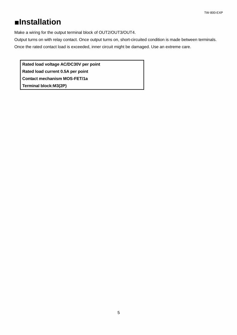
■Installation Make a wiring for the output terminal block of OUT2/OUT3/OUT4.
Output turns on with relay contact. Once output turns on, short-circuited condition is made between terminals.
Once the rated contact load is exceeded, inner circuit might be damaged. Use an extreme care.
Rated load voltage AC/DC30V per point
Rated load current 0.5A per point
Contact mechanism MOS-FET/1a
Terminal block:M3(2P)

TW-800-EXP
6
■Setting It needs “pairing” a transmitter and a receiver before using for OUT2-OUT4.
Transmitter and receiver communicate by recognizing the other party's recognition signal by pairing.
●Pairing for OUT2-OUT4 (Registration)
1. Power Switch is turned on pushing the lighting switch of output (OUT2-OUT4) that you want to register of the
receiver.
To enter “Pairing mode” only 10 seconds with flashing the lighting switch for pairing.
2. You continue pushing the “pairing switch” over 3seconds of transmitter by a long and slender thing.
3. It is completed the pairing between transmitter and receiver, then the lighting switch of receiver is turned off.
4. It can communicate with transmitter being pairing, you turn off the power switch of receiver once.
●Delete the pairing
1. Turn on the power switch while pressing the lighting switch of output (OUT2-OUT4) that you want to delete
the pairing.
To enter “Pairing mode” only 10 seconds with flashing the lighting switch for pairing.
2. You continue pushing the “lighting switch for pairing” over 2 seconds, then the lighting switch is turned on.
The transmitter which is register by pairing is deleted.
*Caution
Please keep in mind that a transmitter cancels the pairing information (registration information on a receiver)
which was carrying out the memory, and the communication with the receiver which was carrying out pairing
becomes impossible if a receiver carries out the long aggressiveness of the pairing switch of a transmitter 3
seconds or more in the state where it is not in pairing mode.
●Output setting of OUT2-OUT4
Since an output setting (relay output time, double count prevention time, buzzer operation) of output OUT2-OUT4
of the extension follows a setting of the DIP switch of TW-800R main part, OUT1-OUT4 becomes the same output
setting. It cannot set up for every output.
The lighting switch for pairing.
Power switch
Pairing switch

TW-800-EXP
7
■How to use 1. Power switch of receiver is turned on. Please confirm the LED situation as turning off.
The LEDs for OUT1, OUT2, OUT3 and OUT4 turn off if they are paired with the transmitter, and they turn on if
they are not paired with the transmitter. If all the LEDs turn on, then no transmitter is paired. Please perform
pairing.
2. The transmitter transmits the signal when the limit switch is turned on.
When the communication is done normally, receiver output the relay output and receiver sounds the buzzer
according to setting. Green LED of transmitter turns on 1 time.
When the signal from other transmitters is normally received while buzzer sounds, because buzzer sounds
overlaps, it will be 1 time. Relay output is operated, respectively.
When the communication is not done normally, receiver doesn’t move.
Red LED of Transmitter flashes 10 times
While the receiver output relay output or while receiver is in double count protect time, receiver transmit the
busy signal to transmitter. When the transmitter receives the busy signal, the Green LED of transmitter is
flashed 3 times.
Transmitter Receiver
Communication OK Green LED 1 time flashing LED 1 time flashing
Communication NG Red LED 10 times flashing -
BUSY Green LED 3 times flashing -
Buzzer sound time is usually for 100ms.When the relay output is set 50mses and double count protect time is
set 10mses, Buzzer sound time is 50msec.
*When the transmitter is not done “Pairing” transmits, Red LED will be flashing 3 times.
LED for receiving (Green)
(Lighting switch for pairing) LED (Green & Red)

TW-800-EXP
8
●Test switch
There is a test switch for checking the battery and communication. When the transmitter transmits the signal by
test switch not limit switch, receiver doesn’t output relay output. But LED of receiver only turns on.
Also transmitter make a checking the battery at pushing the test switch. You can know the battery situation by
transmitter LED and Receiver LED.
The test switch also can be used as a pairing switch. A long press on the test switch (3 seconds or more) resets
the pairing with the receiver and prevents communication with the registered receiver. When pairing is reset by
mistake, perform the pairing procedure again.
Transmitter Receiver
Communication check OK: Green LED 1 time flashing
NG: Red LED 10 times flashing LED 1 time flashing
Battery power low level Red LED 1 seconds lighting LED 2 times flashing
*Transmitter displays the situation of battery power low level after transmitter displays communication check
result (OK or NG).
Test switch

TW-800-EXP
9
■Specification
●TW-800 common specification
Items Specification
Standard 2.4GHz Small electric power data communication system
Emission designation F1D
Frequency band 2,403MHz-2,476MHz
Channel 76CH
Modulation way GFSK
Communication way Simplex
Power of antenna 2.1mW
●Receiver TW-800R-EXP
Items Specification
Output
Contact output * 4point (Terminal block:M3(2P))
Contact mechanism MOS-FET/1a
Rated load voltage AC/DC30V per point
Rated load current 0.5A per point
Buzzer Piezoelectric Buzzer 95dB/m
Display
LED for receiving(Green) * 4point
(Combination lighting switch for pairing)
Power LED(Red) * 1point
Power source DC24V±20%(DC19-28V)
Terminal block: M3(2P)
Consumption current 80mA or less
Operating environment Temperature 0-50 degree Humidity Under 80%
Dimension 130W*100H*30D mm (Except projection)
Weight Approx. 430g
Antenna
Dipole antenna (Diversity type)
*ANT2 is fixed by resin before shipment by regulation of FCC/IC in an
applicable country.
Switch Power switch *1 point
6-position DIP switch for setting * 1point
*SMA Connector antenna type for ANT2 is “M3.5-S SMA-P-MALE”
*The above-mentioned specification is a thing in the state where the extension unit was connected with
main body TW-800R.

TW-800-EXP
10
■Dimensional drawing
●Receiver TW-800R-EXP
TW-800-EXP
11
■After service and Warranty If something is wrong. If you should find anything wrong with the machine when using it under normal
conditions, check the following items and contact the outlet store through which you purchased the product or
our Sales Office.
Product name / Serial No. / Working
environment,
External devices connected,
Operating sequence to error initiation,
Specific description of error, etc.
Provisions of warranty
The provisions of warranty are set forth by us for warranty of the product after shipment so that the product
can be used with a sense of security after purchased. In case our product is out of order, we will provide
repair or replacement under the provisions of warranty.
Warranty period
Besides, as long as there is not providing, the warranty period shall be 13 months after shipping the
products. During the warranty period, we will provide free-of-charge repair subject to the provisions of
warranty set forth in the warranty certificate.
If you have anything unclear about the repair or follow-up service during the warranty period, please contact
the outlet store through which you purchased the product or our Sales Office.
Scope of warranty
If the product should get out of order under the normal conditions of use by the customer, we will repair the
failed section(s) free of charge or exchange the new one free of charge subject to the provisions of warranty.
Please contact the outlet store through which you purchased the product or our Sales Office.
Also, the warranty period shall be 13 months after shipping the product or shall be 6 months after shipping
substituting goods. The warranty periods will be applied the period visited later.
Note, however, that free-of-charge repair under this warranty is limited to the hardware components of the
product. Even during the warranty period, the customer shall be responsible for repair cost if any of the
following applies:
1. Troubles or damages occurring due to improper handling by the customer, such as a fall, a shock, etc.
During transportation or movement of the product by the customer.
2. Troubles caused by overhaul or remodeling of the main body by the customer.
3. Troubles or damages caused by fire, earthquake, flood damage, or other natural disasters, as well as by
abnormal voltage.
4. Troubles resulting from any trouble of devices connected to the product, which Devices are other than
those designated by us.
5. Troubles with the accessories (AC adapter, antenna, connection cables, or the like) except the main body.
6. Repairing, adjustment, modification by except our company
7. Replacement of consumables and limited-life items (including batteries).

TW-800-EXP
12
Consumables and limited-life items include, but not limited to:
(1) Switches (limit switches, pushbutton switches, or the like)
(2) Battery cells or batteries (dry batteries, button batteries, or the like)
(3) Other items subject to consumption or limitation of life caused by use.
8. Troubles occurring due to handling against the use instructions or precautions specified in this operation
manual.
Initial defects
The period within 30 days from the date of shipping the product is defined as the initial defect period for the
product. The product will be replaced with a new one or repaired free of charge provided that it is returned
to the outlet store through which you purchased the product or our Sales Office, checked, and recognized
as having initial defects. For initial defects, we shall be responsible for the shipping cost.
But it is in Japan only. In case of purchasing the products out of Japan, it will be decided
after conference about shipping cost for returning back, insurance cost, custom duty.
Disclaimer
We will assume no liability for any damages or monetary losses, direct or indirect, arising out of troubles,
failures, or use of the product.
Repair service period
Only if we have the stock of parts for repairing, even if after finishing the warranty period, we will repair the
product within 5 years after end of production for a fee.However, we reserve the right to use substitute parts
or devices for repairing purposes if there are unavoidable reasons such as unavailability of service parts.
Others
●Independent of the warranty period, the product to be repaired shall in principle be brought into our site
because of the necessity of using measuring instruments or the like for adjustments etc., and the shipping
cost etc. incurred in bringing the product into our site shall be borne by the customer.
●In such cases where you request a trip to your place for repair or need substitute devices
during the warranty period, please contact the outlet store through which you purchased the product or our
Sales Office. We will correspond for a fee.
●We reserve the right to refuse replacement or repair if we are unable to reproduce the concerned failure at
our engineering department after receipt of a request for repair.
In addition, an additional charge may be made to the customer for the technical examination cost incurred in
reproducing the failure.
●The information in this manual, our website, catalog we supply, is subject to change without prior notice.
Please be forewarned.


HERUTU ELECTRONICS CORPORATION
62-1 Toyooka-cho, Kita-ku, Hamamatsu, Shizuoka, 433-8103 Japan
(Sales dept) TEL.+81-053-438-3555 FAX. +81-53-438-3411
Website URL https://www.herutu.co.jp/en/ E-mail [email protected]