twido programmable controllers software reference guide · 31003914 00 twido programmable...
TRANSCRIPT

3100
3914
00
TwidoProgrammable ControllersSoftware Reference GuideTWD USE 10AE Version 1.0

2 TWD USE 10AE 05/2002

Table of Contents
Safety Information . . . . . . . . . . . . . . . . . . . . . . . . . . . . . . . . . . . . 9
About the Book . . . . . . . . . . . . . . . . . . . . . . . . . . . . . . . . . . . . . .13
Part I Description of Twido Software . . . . . . . . . . . . . . . . . . . . 15At a Glance . . . . . . . . . . . . . . . . . . . . . . . . . . . . . . . . . . . . . . . . . . . . . . . . . . . . . 15
Chapter 1 Introduction to Twido Software . . . . . . . . . . . . . . . . . . . . . . . . 17At a Glance . . . . . . . . . . . . . . . . . . . . . . . . . . . . . . . . . . . . . . . . . . . . . . . . . . . . . 17Introduction to TwidoSoft. . . . . . . . . . . . . . . . . . . . . . . . . . . . . . . . . . . . . . . . . . . 18Introduction to Twido Languages . . . . . . . . . . . . . . . . . . . . . . . . . . . . . . . . . . . . 19
Chapter 2 Twido Language Objects . . . . . . . . . . . . . . . . . . . . . . . . . . . . .23At a Glance . . . . . . . . . . . . . . . . . . . . . . . . . . . . . . . . . . . . . . . . . . . . . . . . . . . . . 23Language Object Validation . . . . . . . . . . . . . . . . . . . . . . . . . . . . . . . . . . . . . . . . 24Bit Objects . . . . . . . . . . . . . . . . . . . . . . . . . . . . . . . . . . . . . . . . . . . . . . . . . . . . . . 25Word Objects. . . . . . . . . . . . . . . . . . . . . . . . . . . . . . . . . . . . . . . . . . . . . . . . . . . . 27Addressing Bit Objects . . . . . . . . . . . . . . . . . . . . . . . . . . . . . . . . . . . . . . . . . . . . 29Addressing Word Objects . . . . . . . . . . . . . . . . . . . . . . . . . . . . . . . . . . . . . . . . . . 30Addressing Inputs/Outputs . . . . . . . . . . . . . . . . . . . . . . . . . . . . . . . . . . . . . . . . . 31Network Addressing . . . . . . . . . . . . . . . . . . . . . . . . . . . . . . . . . . . . . . . . . . . . . . 33Function Block Objects . . . . . . . . . . . . . . . . . . . . . . . . . . . . . . . . . . . . . . . . . . . . 34Structured Objects. . . . . . . . . . . . . . . . . . . . . . . . . . . . . . . . . . . . . . . . . . . . . . . . 35Indexed Words . . . . . . . . . . . . . . . . . . . . . . . . . . . . . . . . . . . . . . . . . . . . . . . . . . 37Symbolizing Objects . . . . . . . . . . . . . . . . . . . . . . . . . . . . . . . . . . . . . . . . . . . . . . 39
Chapter 3 User Memory . . . . . . . . . . . . . . . . . . . . . . . . . . . . . . . . . . . . . . . 41User Memory Structure . . . . . . . . . . . . . . . . . . . . . . . . . . . . . . . . . . . . . . . . . . . . 41
Chapter 4 Controller Operating Modes . . . . . . . . . . . . . . . . . . . . . . . . . . .45At a Glance . . . . . . . . . . . . . . . . . . . . . . . . . . . . . . . . . . . . . . . . . . . . . . . . . . . . . 45Cyclic Scan . . . . . . . . . . . . . . . . . . . . . . . . . . . . . . . . . . . . . . . . . . . . . . . . . . . . . 46Periodic Scan . . . . . . . . . . . . . . . . . . . . . . . . . . . . . . . . . . . . . . . . . . . . . . . . . . . 48Checking Scan Time . . . . . . . . . . . . . . . . . . . . . . . . . . . . . . . . . . . . . . . . . . . . . . 51Operating Modes. . . . . . . . . . . . . . . . . . . . . . . . . . . . . . . . . . . . . . . . . . . . . . . . . 52
TWD USE 10AE 05/2002 3

Dealing with Power Cuts and Power Restoration . . . . . . . . . . . . . . . . . . . . . . . . 54Dealing with a Warm Restart . . . . . . . . . . . . . . . . . . . . . . . . . . . . . . . . . . . . . . . . 56Dealing with a Cold Start . . . . . . . . . . . . . . . . . . . . . . . . . . . . . . . . . . . . . . . . . . . 58Initializing the Controller. . . . . . . . . . . . . . . . . . . . . . . . . . . . . . . . . . . . . . . . . . . . 60
Part II Special Functions . . . . . . . . . . . . . . . . . . . . . . . . . . . . . . .61At a Glance . . . . . . . . . . . . . . . . . . . . . . . . . . . . . . . . . . . . . . . . . . . . . . . . . . . . . 61
Chapter 5 Communications . . . . . . . . . . . . . . . . . . . . . . . . . . . . . . . . . . . . 63At a Glance . . . . . . . . . . . . . . . . . . . . . . . . . . . . . . . . . . . . . . . . . . . . . . . . . . . . . 63Communications Overview . . . . . . . . . . . . . . . . . . . . . . . . . . . . . . . . . . . . . . . . . 64TwidoSoft to Controller Communications. . . . . . . . . . . . . . . . . . . . . . . . . . . . . . . 65Remote Link Communications. . . . . . . . . . . . . . . . . . . . . . . . . . . . . . . . . . . . . . . 67ASCII Communications . . . . . . . . . . . . . . . . . . . . . . . . . . . . . . . . . . . . . . . . . . . . 79Modbus Communications . . . . . . . . . . . . . . . . . . . . . . . . . . . . . . . . . . . . . . . . . . 90Standard Modbus Requests . . . . . . . . . . . . . . . . . . . . . . . . . . . . . . . . . . . . . . . 106
Chapter 6 Built-In Analog Functions . . . . . . . . . . . . . . . . . . . . . . . . . . . 111At a Glance . . . . . . . . . . . . . . . . . . . . . . . . . . . . . . . . . . . . . . . . . . . . . . . . . . . . 111Potentiometers. . . . . . . . . . . . . . . . . . . . . . . . . . . . . . . . . . . . . . . . . . . . . . . . . . 112Analog Channel . . . . . . . . . . . . . . . . . . . . . . . . . . . . . . . . . . . . . . . . . . . . . . . . . 114
Chapter 7 Managing Analog Modules . . . . . . . . . . . . . . . . . . . . . . . . . . 115At a Glance . . . . . . . . . . . . . . . . . . . . . . . . . . . . . . . . . . . . . . . . . . . . . . . . . . . . 115Analog Module Overview. . . . . . . . . . . . . . . . . . . . . . . . . . . . . . . . . . . . . . . . . . 116Addressing Analog Inputs and Outputs . . . . . . . . . . . . . . . . . . . . . . . . . . . . . . . 117Configuring Analog Inputs and Outputs . . . . . . . . . . . . . . . . . . . . . . . . . . . . . . . 119Example of Using Analog Modules . . . . . . . . . . . . . . . . . . . . . . . . . . . . . . . . . . 121
Chapter 8 Operator Display Operation . . . . . . . . . . . . . . . . . . . . . . . . . . 123At a Glance . . . . . . . . . . . . . . . . . . . . . . . . . . . . . . . . . . . . . . . . . . . . . . . . . . . . 123Operator Display . . . . . . . . . . . . . . . . . . . . . . . . . . . . . . . . . . . . . . . . . . . . . . . . 124Controller Identification and State Information. . . . . . . . . . . . . . . . . . . . . . . . . . 127System Objects and Variables. . . . . . . . . . . . . . . . . . . . . . . . . . . . . . . . . . . . . . 129Serial Port Settings . . . . . . . . . . . . . . . . . . . . . . . . . . . . . . . . . . . . . . . . . . . . . . 134Time of Day Clock . . . . . . . . . . . . . . . . . . . . . . . . . . . . . . . . . . . . . . . . . . . . . . . 134Real-Time Correction Factor . . . . . . . . . . . . . . . . . . . . . . . . . . . . . . . . . . . . . . . 136
Part III Description of Twido Languages . . . . . . . . . . . . . . . . . 137At a Glance . . . . . . . . . . . . . . . . . . . . . . . . . . . . . . . . . . . . . . . . . . . . . . . . . . . . 137
Chapter 9 Ladder Language . . . . . . . . . . . . . . . . . . . . . . . . . . . . . . . . . . 139At a Glance . . . . . . . . . . . . . . . . . . . . . . . . . . . . . . . . . . . . . . . . . . . . . . . . . . . . 139Introduction to Ladder Diagrams . . . . . . . . . . . . . . . . . . . . . . . . . . . . . . . . . . . . 140Programming Principles for Ladder Diagrams. . . . . . . . . . . . . . . . . . . . . . . . . . 142Ladder Diagram Blocks . . . . . . . . . . . . . . . . . . . . . . . . . . . . . . . . . . . . . . . . . . . 144
4 TWD USE 10AE 05/2002

Ladder Language Graphic Elements. . . . . . . . . . . . . . . . . . . . . . . . . . . . . . . . . 147Special Ladder Instructions OPEN and SHORT . . . . . . . . . . . . . . . . . . . . . . . . 150Programming Advice. . . . . . . . . . . . . . . . . . . . . . . . . . . . . . . . . . . . . . . . . . . . . 151Ladder/List Reversibility . . . . . . . . . . . . . . . . . . . . . . . . . . . . . . . . . . . . . . . . . . 156Guidelines for Ladder/List Reversibility . . . . . . . . . . . . . . . . . . . . . . . . . . . . . . . 157Program Documentation . . . . . . . . . . . . . . . . . . . . . . . . . . . . . . . . . . . . . . . . . . 159
Chapter 10 Instruction List Language . . . . . . . . . . . . . . . . . . . . . . . . . . . . 161At a Glance . . . . . . . . . . . . . . . . . . . . . . . . . . . . . . . . . . . . . . . . . . . . . . . . . . . . 161Overview of List Programs . . . . . . . . . . . . . . . . . . . . . . . . . . . . . . . . . . . . . . . . 162Operation of List Instructions. . . . . . . . . . . . . . . . . . . . . . . . . . . . . . . . . . . . . . . 164List Language Instructions . . . . . . . . . . . . . . . . . . . . . . . . . . . . . . . . . . . . . . . . 165Using Parentheses . . . . . . . . . . . . . . . . . . . . . . . . . . . . . . . . . . . . . . . . . . . . . . 169Stack Instructions (MPS, MRD, MPP). . . . . . . . . . . . . . . . . . . . . . . . . . . . . . . . 172
Chapter 11 Grafcet . . . . . . . . . . . . . . . . . . . . . . . . . . . . . . . . . . . . . . . . . . . 175At a Glance . . . . . . . . . . . . . . . . . . . . . . . . . . . . . . . . . . . . . . . . . . . . . . . . . . . . 175Description of Grafcet Instructions . . . . . . . . . . . . . . . . . . . . . . . . . . . . . . . . . . 176Description of Grafcet Program Structure . . . . . . . . . . . . . . . . . . . . . . . . . . . . . 180Actions Associated with Grafcet Steps . . . . . . . . . . . . . . . . . . . . . . . . . . . . . . . 183
Part IV Description of Instructions and Functions . . . . . . . . . 185At a Glance . . . . . . . . . . . . . . . . . . . . . . . . . . . . . . . . . . . . . . . . . . . . . . . . . . . . 185
Chapter 12 Basic Instructions . . . . . . . . . . . . . . . . . . . . . . . . . . . . . . . . . . 187At a Glance . . . . . . . . . . . . . . . . . . . . . . . . . . . . . . . . . . . . . . . . . . . . . . . . . . . . 187
12.1 Boolean Processing . . . . . . . . . . . . . . . . . . . . . . . . . . . . . . . . . . . . . . . . . . . . . 188Introduction to Boolean Processing. . . . . . . . . . . . . . . . . . . . . . . . . . . . . . . . . . 188Boolean Instructions . . . . . . . . . . . . . . . . . . . . . . . . . . . . . . . . . . . . . . . . . . . . . 189Understanding the Format for Describing Boolean Instructions . . . . . . . . . . . . 192Load Instructions (LD, LDN, LDR, LDF) . . . . . . . . . . . . . . . . . . . . . . . . . . . . . . 194Store Instructions (ST, STN, R, S) . . . . . . . . . . . . . . . . . . . . . . . . . . . . . . . . . . 196Logical AND Instructions (AND, ANDN, ANDR, ANDF) . . . . . . . . . . . . . . . . . . 198Logical OR Instructions (OR, ORN, ORR, ORF). . . . . . . . . . . . . . . . . . . . . . . . 200Exclusive OR Instructions (XOR, XORN, XORR, XORF) . . . . . . . . . . . . . . . . . 202NOT Instruction (N) . . . . . . . . . . . . . . . . . . . . . . . . . . . . . . . . . . . . . . . . . . . . . . 204
12.2 Basic Function Blocks . . . . . . . . . . . . . . . . . . . . . . . . . . . . . . . . . . . . . . . . . . . . 205At a Glance . . . . . . . . . . . . . . . . . . . . . . . . . . . . . . . . . . . . . . . . . . . . . . . . . . . . 205Basic Function Blocks . . . . . . . . . . . . . . . . . . . . . . . . . . . . . . . . . . . . . . . . . . . . 206Principles for Programming Basic Function Blocks. . . . . . . . . . . . . . . . . . . . . . 208Timer Function Block (%TMi) . . . . . . . . . . . . . . . . . . . . . . . . . . . . . . . . . . . . . . 210TOF Type of Timer . . . . . . . . . . . . . . . . . . . . . . . . . . . . . . . . . . . . . . . . . . . . . . 212TON Type of Timer . . . . . . . . . . . . . . . . . . . . . . . . . . . . . . . . . . . . . . . . . . . . . . 213TP Type of Timer. . . . . . . . . . . . . . . . . . . . . . . . . . . . . . . . . . . . . . . . . . . . . . . . 214Programming and Configuring Timers . . . . . . . . . . . . . . . . . . . . . . . . . . . . . . . 215Up/Down Counter Function Block (%Ci) . . . . . . . . . . . . . . . . . . . . . . . . . . . . . . 218
TWD USE 10AE 05/2002 5

Programming and Configuring Counters . . . . . . . . . . . . . . . . . . . . . . . . . . . . . . 222Shift Bit Register Function Block (%SBRi). . . . . . . . . . . . . . . . . . . . . . . . . . . . . 223Step Counter Function Block (%SCi). . . . . . . . . . . . . . . . . . . . . . . . . . . . . . . . . 226
12.3 Numerical Processing . . . . . . . . . . . . . . . . . . . . . . . . . . . . . . . . . . . . . . . . . . . . 230Introduction to Numerical Processing . . . . . . . . . . . . . . . . . . . . . . . . . . . . . . . . 230Introduction to Numerical Instructions . . . . . . . . . . . . . . . . . . . . . . . . . . . . . . . . 231Assignment Instructions. . . . . . . . . . . . . . . . . . . . . . . . . . . . . . . . . . . . . . . . . . . 232Comparison Instructions . . . . . . . . . . . . . . . . . . . . . . . . . . . . . . . . . . . . . . . . . . 236Arithmetic Instructions . . . . . . . . . . . . . . . . . . . . . . . . . . . . . . . . . . . . . . . . . . . . 238Logic Instructions. . . . . . . . . . . . . . . . . . . . . . . . . . . . . . . . . . . . . . . . . . . . . . . . 242Shift Instructions . . . . . . . . . . . . . . . . . . . . . . . . . . . . . . . . . . . . . . . . . . . . . . . . 244Conversion Instructions . . . . . . . . . . . . . . . . . . . . . . . . . . . . . . . . . . . . . . . . . . . 246
12.4 Program Instructions . . . . . . . . . . . . . . . . . . . . . . . . . . . . . . . . . . . . . . . . . . . . . 248Introduction to Program Instructions . . . . . . . . . . . . . . . . . . . . . . . . . . . . . . . . . 248END Instructions . . . . . . . . . . . . . . . . . . . . . . . . . . . . . . . . . . . . . . . . . . . . . . . . 249NOP Instruction . . . . . . . . . . . . . . . . . . . . . . . . . . . . . . . . . . . . . . . . . . . . . . . . . 251Jump Instructions. . . . . . . . . . . . . . . . . . . . . . . . . . . . . . . . . . . . . . . . . . . . . . . . 252Subroutine Instructions . . . . . . . . . . . . . . . . . . . . . . . . . . . . . . . . . . . . . . . . . . . 253
Chapter 13 Advanced Instructions . . . . . . . . . . . . . . . . . . . . . . . . . . . . . . 255At a Glance . . . . . . . . . . . . . . . . . . . . . . . . . . . . . . . . . . . . . . . . . . . . . . . . . . . . 255
13.1 Advanced Function Blocks. . . . . . . . . . . . . . . . . . . . . . . . . . . . . . . . . . . . . . . . . 256At a Glance . . . . . . . . . . . . . . . . . . . . . . . . . . . . . . . . . . . . . . . . . . . . . . . . . . . . 256Bit and Word Objects Associated with Advanced Function Blocks . . . . . . . . . . 257Programming Principles for Advanced Function Blocks . . . . . . . . . . . . . . . . . . 260LIFO/FIFO Register Function Block (%Ri). . . . . . . . . . . . . . . . . . . . . . . . . . . . . 263LIFO Operation . . . . . . . . . . . . . . . . . . . . . . . . . . . . . . . . . . . . . . . . . . . . . . . . . 265FIFO Operation . . . . . . . . . . . . . . . . . . . . . . . . . . . . . . . . . . . . . . . . . . . . . . . . . 266Programming and Configuring Registers. . . . . . . . . . . . . . . . . . . . . . . . . . . . . . 267Pulse Width Modulation Function Block (%PWM) . . . . . . . . . . . . . . . . . . . . . . . 270Pulse Generator Output Function Block (%PLS) . . . . . . . . . . . . . . . . . . . . . . . . 274Drum Controller Function Block (%DR) . . . . . . . . . . . . . . . . . . . . . . . . . . . . . . . 277Drum Controller Function Block Operation . . . . . . . . . . . . . . . . . . . . . . . . . . . . 279Programming and Configuring Drum Controllers. . . . . . . . . . . . . . . . . . . . . . . . 281Fast Counter Function Block (%FC) . . . . . . . . . . . . . . . . . . . . . . . . . . . . . . . . . 283Very Fast Counter Function Block (%VFC) . . . . . . . . . . . . . . . . . . . . . . . . . . . . 286Transmitting/Receiving Messages - the Exchange Instruction (EXCH). . . . . . . 302Exchange Control Function Block (%MSG). . . . . . . . . . . . . . . . . . . . . . . . . . . . 303
13.2 Clock Functions . . . . . . . . . . . . . . . . . . . . . . . . . . . . . . . . . . . . . . . . . . . . . . . . . 306At a Glance . . . . . . . . . . . . . . . . . . . . . . . . . . . . . . . . . . . . . . . . . . . . . . . . . . . . 306Clock Functions . . . . . . . . . . . . . . . . . . . . . . . . . . . . . . . . . . . . . . . . . . . . . . . . . 307Schedule Blocks . . . . . . . . . . . . . . . . . . . . . . . . . . . . . . . . . . . . . . . . . . . . . . . . 308Time/Date Stamping . . . . . . . . . . . . . . . . . . . . . . . . . . . . . . . . . . . . . . . . . . . . . 311Setting the Date and Time . . . . . . . . . . . . . . . . . . . . . . . . . . . . . . . . . . . . . . . . . 313
6 TWD USE 10AE 05/2002

Chapter 14 System Bits and System Words . . . . . . . . . . . . . . . . . . . . . . . 317At a Glance . . . . . . . . . . . . . . . . . . . . . . . . . . . . . . . . . . . . . . . . . . . . . . . . . . . . 317System Bits (%S) . . . . . . . . . . . . . . . . . . . . . . . . . . . . . . . . . . . . . . . . . . . . . . . 318System Words (%SW). . . . . . . . . . . . . . . . . . . . . . . . . . . . . . . . . . . . . . . . . . . . 325
Glossary . . . . . . . . . . . . . . . . . . . . . . . . . . . . . . . . . . . . . . . . . . . . . 333
Index . . . . . . . . . . . . . . . . . . . . . . . . . . . . . . . . . . . . . . . . . . . . . 345
TWD USE 10AE 05/2002 7

8 TWD USE 10AE 05/2002

§
Safety InformationImportant Information
NOTICE Read these instructions carefully, and look at the equipment to become familiar with the device before trying to install, operate, or maintain it. The following special messages may appear throughout this documentation or on the equipment to warn of potential hazards or to call attention to information that clarifies or simplifies a procedure.
The addition of this symbol to a Danger or Warning safety label indicatesthat an electrical hazard exists, which will result in personal injury if theinstructions are not followed.This is the safety alert symbol. It is used to alert you to potential personalinjury hazards. Obey all safety messages that follow this symbol to avoidpossible injury or death.
DANGER indicates an imminently hazardous situation, which, if not avoided, will result in death, serious injury, or equipment damage.
DANGER
WARNINGWARNING indicates a potentially hazardous situation, which, if not avoided, can result in death, serious injury, or equipment damage.
CAUTIONCAUTION indicates a potentially hazardous situation, which, if not avoided, can result in injury or equipment damage.
TWD USE 10AE 05/2002 9

PLEASE NOTE Electrical equipment should be serviced only by qualified personnel. No responsi-bility is assumed by Schneider Electric for any consequences arising out of the use of this material. This document is not intended as an instruction manual for untrained persons. Assembly and installation instructions are provided in the Twido Hardware Reference Guide, TWD USE 10AE.© 2002 Schneider Electric All Rights Reserved
ADDITIONAL SAFETY INFORMATION
Those responsible for the application, implementation or use of this product must ensure that the necessary design considerations have been incorporated into each application, completely adhering to applicable laws, performance and safety requirements, regulations, codes and standards.
10 TWD USE 10AE 05/2002

Safety Information
GENERAL WARNINGSAND CAUTIONS WARNING
EXPLOSION HAZARD
l Substitution of components may impair suitability for Class I, Div 2 compliance.
l Do not disconnect equipment unless power has been switched off or the area is known to be non-hazardous.
Failure to observe this precaution can result in severe injury or equipment damage.
WARNING
UNINTENDED EQUIPMENT OPERATION
l Turn power off before installing, removing, wiring, or maintaining.l This product is not intended for use in safety critical machine
functions. Where personnel and or equipment hazards exist, use appropriate hard-wired safety interlocks.
l Do not disassemble, repair, or modify the modules.l This controller is designed for use within an enclosure.l Install the modules in the operating environment conditions
described.l Use the sensor power supply only for supplying power to sensors
connected to the module.l Use an IEC60127-approved fuse on the power line and output circuit
to meet voltage and current requirements. Recommended fuse: Liitlefuse 5x20 mm slowblow type 218000 series/Type T.
Failure to observe this precaution can result in severe injury or equipment damage.
TWD USE 10AE 05/2002 11

12 TWD USE 10AE 05/2002

About the Book
At a Glance
Document Scope This is the Software Reference manual for Twido programmable controllers and consists of the following major parts:l Description of the Twido programming software and an introduction to the
fundamentals needed to program Twido controllers.l Description of communications, managing analog I/O, and other special
functions.l Description of the software languages used to create Twido programs.l Description of instructions and functions of Twido controllers.
Validity Note The information in this manual is applicable only for Twido programmable controllers.
Product Related Warnings
Schneider Electric assumes no responsibility for any errors that appear in this document. No part of this document may be reproduced in any form or means, including electronic, without prior written permission of Schneider Electric.
TWD USE 10AE 05/2002 13

14 TWD USE 10AE 05/2002

TWD USE 10AE 05/2002
I
Description of Twido SoftwareAt a Glance
Overview This part provides an introduction to the software languages and the basic information required to create control programs for Twido programmable controllers.
What’s in this Part?
This part contains the following chapters:
Chapter Chapter Name Page
1 Introduction to Twido Software 17
2 Twido Language Objects 23
3 User Memory 41
4 Controller Operating Modes 45
15

Twido Software
16 TWD USE 10AE 05/2002

TWD USE 10AE 05/2002
1
Introduction to Twido SoftwareAt a Glance
Overview This chapter provides a brief introduction to TwidoSoft, the programming and configuration software for Twido controllers, and to the List, Ladder, and Grafcet programming languages used to create control programs.
What’s in this Chapter?
This chapter contains the following topics:
Topic Page
Introduction to TwidoSoft 18
Introduction to Twido Languages 19
17

Twido Software Languages
Introduction to TwidoSoft
Introduction TwidoSoft is a graphical development environment for creating, configuring, and maintaining applications for Twido programmable controllers. TwidoSoft allows you to enter control programs using the TwidoSoft Ladder or List program editors and then transfer the program to run on a controller.
TwidoSoft TwidoSoft is a 32-bit Windows-based program for a personal computer (PC) running Microsoft Windows 98 Second Edition or Microsoft Windows 2000 Professional operating systems.The main software features of TwidoSoft:l Standard Windows user interfacel Program and configure Twido controllersl Controller communication and controlFor more details, see the TwidoSoft Operation Guide.
18 TWD USE 10AE 05/2002

Twido Software Languages
Introduction to Twido Languages
Introduction A programmable controller reads inputs, writes to outputs, and solves logic based on a control program. Creating a control program for a Twido controller consists of writing a series of instructions in one of the Twido programming languages.
Twido Languages
The following languages can be used to create Twido control programs:l Instruction List language
An Instruction List program is a series of logical expressions written as a sequence of Boolean instructions.
l Ladder diagramsA Ladder diagram is a graphical means of displaying a logical expression.
l GrafcetTwido supports the use of Grafcet list instructions, but not graphical Grafcet.
You can use a personal computer (PC) to create and edit Twido control programs using these programming languages.A List/Ladder reversibility feature allows you to conveniently reverse a program from Ladder to List and from List to Ladder.
Instruction List Language
A program written in Instruction List language consists of a series of instructions executed sequentially by the controller. The following is an example of a List program.
0 BLK %C81 LDF %I0.12 R3 LD %I0.24 AND %M05 CU6 OUT_BLK7 LD D8 AND %M19 ST %Q0.410 END_BLK
TWD USE 10AE 05/2002 19

Twido Software Languages
Ladder Diagrams Ladder diagrams are similar to relay logic diagrams that are used to represent relay control circuits. Graphic elements such as coils, contacts, and blocks represent instructions. The following is an example of a Ladder diagram.
R
S
CU
CD
E
D
F
%C8
ADJ Y%C8.P 777
N%I0.1
%I0.2 %M0
%M1 %Q0.4
20 TWD USE 10AE 05/2002

Twido Software Languages
Grafcet Language
Grafcet is an analytical method which divides any sequential control system into a series of steps which have associated actions, transitions, and conditions. The following illustration shows examples of Grafcet instructions in List and Ladder programs respectively.
0 -*- 31 LD %M102 # 43 # 54 -*- 45 LD %I0.76 # 67 -*- 58 LD %M159 # 710 ...
–*–5
–*–3
–*–4
#
#
#
#
%M10
%I0.7
%M15
4
5
6
7
TWD USE 10AE 05/2002 21

Twido Software Languages
22 TWD USE 10AE 05/2002

TWD USE 10AE 05/2002
2
Twido Language ObjectsAt a Glance
Overview This chapter provides details about the language objects used for programming Twido controllers.
What’s in this Chapter?
This chapter contains the following topics:
Topic Page
Language Object Validation 24
Bit Objects 25
Word Objects 27
Addressing Bit Objects 29
Addressing Word Objects 30
Addressing Inputs/Outputs 31
Network Addressing 33
Function Block Objects 34
Structured Objects 35
Indexed Words 37
Symbolizing Objects 39
23

Twido Language Objects
Language Object Validation
Introduction Word and bit objects are valid if they have been allocated memory space in the controller. To do this, they must be used in the application before downloaded to the controller.
Example The range of valid objects is from zero to the maximum reference for that object type. For example, if your application’s maximum references for memory words is %MW9, then %MW0 through %MW9 are allocated space. %MW10 in this example is not valid and can not be accessed either internally or externally.
24 TWD USE 10AE 05/2002

Twido Language Objects
Bit Objects
Introduction Bit objects are software variable bits that are single bits of data that can be used as operands and tested by Boolean instructions. The following is a list of bit objects:l I/O bitsl Internal bits (memory bits)l System bitsl Step bitsl Bits extracted from words
TWD USE 10AE 05/2002 25

Twido Language Objects
List of Operand Bits
The following table lists and describes all of the main bit objects that are used as operands in Boolean instructions.
Notes:1. Written by the program or by using the Animation Tables Editor.2. See I/O Addressing.3. Except for %SBRi.j and %SCi.j, these bits can be read and written.4. Number is determined by controller model.
Type Description Address or Value
Maximum number Write
access1
Immediate values
0 or 1 (False or True) 0 or 1 - -
InputsOutputs
These bits are the "logical images" of the electrical states of the I/O. They are stored in data memory and updated during each scan of the program logic.
%Ix.y.z2
%Qx.y.z2
Note4 NoYes
Internal (Memory)
Internal bits are internal memory areas used to store intermediary values while a program is running. Note: Unused I/O bits can not be used as internal bits.
%Mi 128 TWDLCAA10DRF, TWDLCAA16DRF256 All other controllers
Yes
System System bits %S0 to %S127 monitor the correct operation of the controller and the correct running of the application program.
%Si 128 According to i
Function blocks
The function block bits correspond to the outputs of the function blocks. These outputs may be either directly connected or used as an object.
%TMi.Q, %Ci.P, and so on.
Note4 No3
Reversible function blocks
Function blocks programmed using reversible programming instructions BLK, OUT_BLK, and END_BLK.
E, D, F, Q, TH0, TH1
Note4 No
Word extracts
One of the 16 bits in some words can be extracted as operand bits.
Varies Varies Varies
Grafcet steps
Bits %X1 to %Xi are associated with Grafcet steps. Step bit Xi is set to 1 when the corresponding step is active, and set to 0 when the step is deactivated.
%X21 62 TWDLCAA10DRF, TWDLCAA16DRF94 TWDLCAA24DRF, Modular Controllers
Yes
26 TWD USE 10AE 05/2002

Twido Language Objects
Word Objects
Introduction Word objects that are addressed in the form of 16-bit words that are stored in data memory and can contain an integer value between -32768 and 32767 (except for the fast counter function block which is between 0 and 65535).Examples of word objects:l Immediate valuesl Internal words (%MWi) (memory words)l Constant words (%KWi)l I/O exchange words (%IWi, %QWi)l System words (%SWi)l Function blocks (configuration and/or runtime data)
Word Formats The contents of the words or values are stored in user memory in 16-bit binary code (two’s complement) using the following convention:
In signed binary notation, bit 15 is allocated by convention to the sign of the coded value:l Bit 15 is 0: the content of the word is a positive value.l Bit 15 is 1: the content of the word is a negative value (negative values are
expressed in two’s complement logic).Words and immediate values can be entered or retrieved in the following format:l Decimal
Min: -32768, Max: 32767 (for example, 1579) l Hexadecimal
Min: 16#0000, Max: 16#FFFF (for example, 16#A536)Alternate syntax: #A536
F
0
|+
E
1
1634
8
D
0
8192
C
1
4096
B
0
2048
A
0
1024
9
1
512
8
0
256
7
0
128
6
1
645
032
4
016
3
1
8
2
1
4
1
0
2
0
1
1
Bit position
Bit state
Bit value
TWD USE 10AE 05/2002 27

Twido Language Objects
Descriptions of Word Objects
The following table describes the word objects.
Words Description Address or value
Maximum number
Write access1
Immediate values
These are integer values that are in the same format as the 16-bit words, which enables values to be assigned to these words.
-
No
Base 10 -32768 to 32767
Base 16 16#0000 to 16#FFFF
Internal (Memory)
Used as "working" words to store values during operation in data memory. Words %MWO to %MW255 are read or written directly by the program.
%MWi 1500 Yes
Constants Store constants or alphanumeric messages. Their content can only be written or modified by using TwidoSoft during configuration. Constant words %KW0 through %KW63 are read-only by the program.
%KWi 64 Yes, only by using TwidoSoft
System These 16-bit words have several functions:l Provide access to data coming directly from the controller by
reading %SWi words (for example, potentiometers.)l Perform operations on the application (for example, adjusting
schedule blocks).
%SWi 128 According to i
Function blocks
These words correspond to current parameters or values of function blocks.
%TM2.P, %Ci.P, etc.
Yes
I/O Exchange words
Assigned to controllers connected as Remote Links. These words are used for communication between controllers.
Inputs %IWi.j Note2 No
Outputs %QWi.j Note2 Yes
Extracted bits It is possible to extract one of the 16 bits from the following words:
Internal %MWi:Xk 1500 Yes
System %SWi:Xk 128 Depends on i
Constants %KWi:Xk 64 No
Input %IWi.j:Xk Note2 No
Output %QWi.j:Xk Note2 Yes
Note: 1. Written by the program or by using the Animation Tables Editor.2. Number is determined by controller model.
28 TWD USE 10AE 05/2002

Twido Language Objects
Addressing Bit Objects
Format Use the following format to address internal, system, and step bit objects:
Description The following table describes the elements in the addressing format.
Examples of bit object addresses:l %M25 = internal bit number 25l %S20 = system bit number 20l %X6 = step bit number 6
Bit Objects Extracted from Words
TwidoSoft is used to extract one of the 16 bits from words. The address of the word is then completed by the bit row extracted according to the following syntax:
Examples:l %MW5:X6 = bit number 6 of internal word %MW5l %QW5.1:X10 = bit number 10 of output word %QW5.1
% M, S, or X i
Symbol Object type Number
Group Element Description
Symbol % The percent symbol always precedes a software variable.
Object type M Internal bits store intermediary values while a program is running.
S System bits provide status and control information for the controller.
X Step bits provide status of step activities.
Number i The maximum number value depends on the number of objects configured.
WORD : X k
Position k = 0 - 15 bitrank in the word address.
Word address
TWD USE 10AE 05/2002 29

Twido Language Objects
Addressing Word Objects
Introduction Addressing word objects, except for input/output addressing (see Addressing Inputs/Outputs, p. 31) and function blocks (see Function Block Objects, p. 34), follows the format described below.
Format Use the following format to address internal, constant and system words.
Description The following table describes the elements in the addressing format.
Examples of word object addressing:l %MW15 = internal word number 15l %KW26 = constant word number 26l %SW30 = system word number 30
% M, K or S W i
Symbol Object type Format Number
Group Element Description
Symbol % The percent symbol always precedes an internal address.
Object type M Internal words store intermediary values while a program is running.
K Constant words store constant values or alphanumeric messages. Their content can only be written or modified by using TwidoSoft.
S System words provide status and control information for the controller.
Format W 16-bit word.
Number i The maximum number value depends on the number of objects configured.
30 TWD USE 10AE 05/2002

Twido Language Objects
Addressing Inputs/Outputs
Introduction Each input/output (I/O) point in a Twido configuration has a unique address: for example, a specific input on a controller is assigned the address of "%I0.0.4".I/O addresses can be assigned for the following hardware:l Controller configured as Remote Link Masterl Controller configured as Remote I/O l Expansion I/O modules
Multiple References to an Output or Coil
In a program, you can have multiple references to a single output or coil. Only the result of the last one solved is updated on the hardware outputs. For example, %Q0.0.0 can be used more than once in a program, and there will not be a warning for multiple occurrences. So it is important to confirm which output will result in the desired operation.
Format Use the following format to address inputs/outputs.
CAUTION
Unintended Operation
No duplicate output checking or warnings are provided. Review the use of the outputs or coils before making changes to them in your application.
Failure to observe this precaution can result in injury or equipment damage.
% I, Q x y z
Symbol Object type Controller position
I/O type Channel number
TWD USE 10AE 05/2002 31

Twido Language Objects
Description The table below describes the I/O addressing format.
Examples The table below shows some examples of I/O addressing.
Group Element Value Description
Symbol % - The percent symbol always precedes an internal address.
Object type I - Input. The "logical image" of the electrical state of a controller or expansion I/O module input.
Q - Output. The "logical image" of the electrical state of a controller or expansion I/O module output.
Controller position
x 01 - 7
Master controller (Remote Link master).Remote controller (Remote Link slave).
I/O type y 01 - 7
Base I/O (local I/O on controller).Expansion I/O modules.
Channel number
z I/O channel number on controller or expansion I/O module. Number of available I/O points depends on controller model or type of expansion I/O module.
I/O object Description
%I0.0.5 Input point number 5 on the base controller (local I/O).
%Q0.3.4 Output point number 4 on expansion I/O module at expansion address number 3 for the base controller (expansion I/O).
%I0.0.3 Input point number 3 on base controller.
%I3.0.1 Input point number 1 on remote I/O controller at remote link address number 3.
%I0.3.2 Input point number 2 on expansion I/O module at address number 3 for the base controller.
32 TWD USE 10AE 05/2002

Twido Language Objects
Network Addressing
Introduction Application data is exchanged between peer controllers and the master controller on a Twido Remote Link network by using the network words %INW and %QNW. See Communications , p. 63 for more details.
Format Use the following format for network addressing.
Description of Format
The table below describes the network addressing format.
Examples The table below shows some examples of networking addressing.
% IN, QN W x j
Symbol Object type Format Controller position
Word
Group Element Value Description
Symbol % - The percent symbol always precedes an internal address.
Object type IN - Network input word. Data transfer from master to peer.
QN - Network output word. Data transfer from peer to master.
Format W - A16-bit word.
Controller position
x 01 - 7
Master controller (Remote Link master).Remote controller (Remote Link slave).
Word j 0 - 3 Each peer controller uses from one to four words to exchange data with the master controller.
Network object Description
%INW3.1 Network word number 1 of remote controller number 3.
%QNW0.3 Network word number 3 of the base controller.
TWD USE 10AE 05/2002 33

Twido Language Objects
Function Block Objects
Introduction Function blocks provide bit objects and specific words that can be accessed by the program.
Example of a Function Block
The following illustration shows a counter function block.
Bit Objects Bit objects correspond to the block outputs. These bits can be accessed by Boolean test instructions using either of the following methods:l Directly (for example, LD E) if they are wired to the block in reversible
programming (see Principles for Programming Basic Function Blocks, p. 208).l By specifying the block type (for example, LD %Ci.E).Inputs can be accessed in the form of instructions.
Word Objects Word objects correspond to specified parameters and values as follows:l Block configuration parameters: some parameters are accessible by the program
(for example, pre-selection parameters), and some are inaccessible by the program (for example, time base).
l Current values: for example, %Ci.V, the current count value.
Objects Accessible by the Program
See the following appropriate sections for a list of objects that are accessible by the program.l For Basic Function Blocks, see Basic Function Blocks, p. 206.l For Advanced Function Blocks, see Bit and Word Objects Associated with
Advanced Function Blocks, p. 257.
Up/down counter block
R E
S D
CD F
CU
%Ci
ADJ Y
%Ci.P 9999
34 TWD USE 10AE 05/2002

Twido Language Objects
Structured Objects
Introduction Structured objects are combinations of simple objects. Twido supports the following types of structured objects:l Bit Stringsl Word Tables
Bit Strings Bit strings are a series of adjacent object bits of the same type and of a defined length (L). Example: Bit string %M8:6
Bit strings can be used with the Assignment instruction (see Assignment Instructions, p. 232).
Available Types of Bits
Available types of bits for bit strings:
Note: %M8:6 is acceptable (8 is a multiple of 8), while %M10:16 is unacceptable (10 is not a multiple of 8).
%M8 %M9 %M10 %M11 %M12 %M13
Type Address Maximum size Write access
Discrete input bits %I0.0:L or %I1.0:L1 0<L<17 No
Discrete output bits %Q0.0:L or %Q1.0:L1 0<L<17 Yes
System bits %Si:Lwith i multiple of 8
0<L<17 and i+L-128 Depending on i
Grafcet Step bits %Xi:Lwith i multiple of 8
0<L<17 and i+L-95 Yes (by program)
Internal bits %Mi:Lwith i multiple of 8
0<L<17 and i+L-256 Yes
Note: (1) Only bits 0...L-1 can be addressed. Not all I/O can be addressed in bit strings.
TWD USE 10AE 05/2002 35

Twido Language Objects
Word Tables Word tables are a series of adjacent words of the same type and of a defined length (L).Example: Word table %KW10:7
Word tables can be used with the Assignment instruction (see Assignment Instructions, p. 232).
Available Types of Words
Available types of words for word tables:
%KW10
%KW16
16 bits
Type Address Maximum size Write access
Internal words %MWi:L 0<L<256 and i+L< or = 1500
Yes
Constant words %KWi:L 0<L and i+L-64 No
System words %SWi:L 0<L and i+L-128 Depending on i
36 TWD USE 10AE 05/2002

Twido Language Objects
Indexed Words
Introduction An indexed word is an internal or constant word with an indexed object address. There are two types of object addressing:l Direct addressingl Indexed addressing
Direct Addressing
A direct address of an object is set and defined when a program is written.Example: %M26 is an internal bit with the direct address 26.
Indexed Addressing
An indexed address of an object provides a method of modifying the address of an object by adding an index to the direct address of an object. The content of the index is added to the object’s direct address. The index is defined by an internal word %MWi. The number of "index words" is unlimited.Example: %MW108[%MW2] is a word with an address consisting of the direct address 108 plus the contents of word %MW2.If word %MW2 has a value of 12, writing to %MW108[%MW2] is equivalent to writing to %MW120 (108 plus 12).
Words Available for Indexed Addressing
The following are the available types of words for indexed addressing.
Indexed words can be used with the Assignment instruction (see Assignment Instructions, p. 232) and in Comparison instructions (see Comparison Instructions, p. 236). This type of addressing enables series of objects of the same type (such as internal words and constants) to be scanned in succession, by modifying the content of the index word via the program.
Type Address Maximum size Write access
Internal words %MWi[MWi] 0-i< or = %MWj<1500 Yes
Constant words %KWi[%MWj] 0-i<%MWj<64 No
TWD USE 10AE 05/2002 37

Twido Language Objects
Index Overflow System Bit %S20
An overflow of the index occurs when the address of an indexed object exceeds the limits of the memory zone containing the same type of object. In summary:l The object address plus the content of the index is less than 0.l The object address plus the content of the index is greater than the largest word
directly referenced in the application. The maximum number is 1499 (for words %MWi) or 63 (for words %KWi).
In the event of an index overflow, the system sets system bit %S20 to 1 and the object is assigned an index value of 0.
Note: The user is responsible for monitoring any overflow. Bit %S20 must be read by the user program for possible processing. The user must confirm that it is reset to 0.%S20 (initial state = 0):l On index overflow: set to 1 by the system.l Acknowledgment of overflow: set to 0 by the user, after modifying the index.
38 TWD USE 10AE 05/2002

Twido Language Objects
Symbolizing Objects
Introduction You can use Symbols to address Twido software language objects by name or customized mnemonics. Using symbols allows for quick examination and analysis of program logic, and greatly simplifies the development and testing of an application.
Example For example, WASH_END is a symbol that could be used to identify a timer function block that represents the end of a wash cycle. Recalling the purpose of this name should be easier than trying to remember the role of a program address such as %TM3.
Guidelines for Defining Symbols
The following are guidelines for defining symbols:l A maximum of 32 characters.l Letters (A-Z), numbers (0 -9), or underscores (_).l First character must be an alphabetical or accented character. You can not use
the percentile sign (%).l Do not use spaces or special characters.l Not case-sensitive. For example, Pump1 and PUMP1 are the same symbol and
can only be used once in an application.
Editing Symbols Symbols are defined and associated with language objects in the Symbol Editor. Symbols and their comments are stored with the application on the PC hard drive, but are not stored on the controller. Therefore, they can not be transferred with the application to the controller.See the TwidoSoft Operation Guide for more details for using symbols.
TWD USE 10AE 05/2002 39

Twido Language Objects
40 TWD USE 10AE 05/2002

TWD USE 10AE 05/2002
3
User MemoryUser Memory Structure
Introduction The controller memory accessible by an user application is divided into two distinct sets:l Bit valuesl Word values (16-bit signed values)
Bit Memory The bit memory is stored in the internal RAM memory that is integrated into the controller. It contains the map of 1280 bit objects.
Role of the Words Memory
The words memory (16 bits) supports:l Data: dynamic application data and system data.l Program: descriptors and executable code for tasks.l Constants: constant words, initial values, and input/output configuration.
Memory Types The following are the different types of memory for Twido controllers.l Internal RAM (integrated)
This is integrated controller RAM memory. The first 10KB of internal RAM memory is fast RAM while the next 32 KB is standard RAM. Internal RAM contains program, constants, and data.
l Internal EEPROMAn integrated 32KB EEPROM that provides internal backup in the controller of an application. Protects application from corruption due to battery failure or a power outage lasting longer than 30 days. Contains program and constants.
l External memory backup cartridgeAn optional external EEPROM cartridge for backing up an application or allowing for a larger application. Can be used to update the application in controller RAM. Contains program and constants, but no data.
41

User Memory
Structure without External Memory Cartridge
The following diagram describes the memory structure without an external memory cartridge.
The internal EEPROM is integrated into the controller and provides 32 KB of memory for the following:l The application program (32 KB)l 512 internal words (%MWi)
Structure with External Memory Cartridge
The optional external memory cartridge provides back up for programs and constants, and also offers expanded memory for larger applications.The following diagram describes the memory structure with the external memory cartridge.
The internal 32 KB EEPROM can save 512 internal words (%MWi).
Data
Program
Constants
Savingprogram and
constants
Saving%MW
Internal RAM
InternalEEPROM
Data
Program
Constants
InternalRAM
External EEPROM cartridge
Fieldcannot be used
Saving%MW
InternalEEPROM
42 TWD USE 10AE 05/2002

User Memory
Saving Memory The controller internal RAM memory can be saved by one of the following:l Internal battery (for up to 30 days)l Internal EEPROM (maximum of 32 KB)l Optional external memory cartridge (maximum of 64KB)Transferring the application from the internal EEPROM memory to the RAM memory is done automatically when the application is lost in RAM (if it has not been saved or if there is no battery). Manual transfer can also be performed using TwidoSoft.
Memory Configurations
The following table describes the types of memory configurations possible with Twido controllers.
Memory typeCompact Controllers Modular Controllers
10DRF 16DRF 24DRF 20DUK20DTK
20DRT 40DUK40DTK
Internal RAM 10KB 32KB 32KB 32KB 32KB 32KB
Available extended memory*
64KB 64KB
Maximum application size
10KB 32KB 32KB 32KB 32KB or 64KB*
32KB or 64KB*
Maximum external backup
32KB 32KB 32KB 64KB 32KB or64KB
32KB or64KB
Note: *Memory can be expanded to 64KB for the TWDLMDA20DRT, TWDLMDA40DUK, and TWDLMDA40DTK controllers by installing the optional 64KB external memory cartridge. The cartridge must remain installed for running and backing up the application.
TWD USE 10AE 05/2002 43

User Memory
44 TWD USE 10AE 05/2002

TWD USE 10AE 05/2002
4
Controller Operating ModesAt a Glance
Overview This chapter describes controller operating modes and cyclic and periodic program execution. Included are details about power outages and restoration.
What’s in this Chapter?
This chapter contains the following topics:
Topic Page
Cyclic Scan 46
Periodic Scan 48
Checking Scan Time 51
Operating Modes 52
Dealing with Power Cuts and Power Restoration 54
Dealing with a Warm Restart 56
Dealing with a Cold Start 58
Initializing the Controller 60
45

Controller Operating Modes
Cyclic Scan
Introduction The cyclic scan binds the master task cycles one after the other without waiting for anything except the inevitable system processing. After having effected the output update (third phase of the task cycle), the system executes a certain number of its own tasks and immediately triggers another task cycle.
Operation The following drawing shows the running phases of the cyclical scan time.
Description of Operating Phases
The table below describes the operating phases.
Note: The scan time of the user program is monitored by the controller watchdog timer and must not exceed 150 ms. Otherwise a fault appears causing the controller to stop immediately in Halt mode. Outputs in this mode are forced to their default fallback state.
Processing the program
Processing the program
I.P. %I %Q I.P. %I %Q
Scan n time Scan n+1 time
Address Phase Description
I.P. Internal processing
The system implicitly monitors the controller (managing system bits and words, updating current timer values, updating status lights, detecting RUN/STOP switches, etc.) and processes requests from TwidoSoft (modifications and animation).
%I Acquisition of inputs
Writing to the memory the status of information on discrete and application specific module inputs associated with the task.
- Program processing
Running the application program written by the user.
%Q Updating outputs
Writing output bits or words associated with discrete and application specific modules associated with the task according to the status defined by the application program.
46 TWD USE 10AE 05/2002

Controller Operating Modes
Operating Mode Controller in RUN, the processor performs:l Internal processingl Acquiring inputsl Processing the application programl Updating outputsController in STOP, the processor performs:l Internal processingl Acquiring inputs
Illustration The following illustration shows the operating cycles.
Check Cycle The check cycle is performed by watchdog.
Internal Processing
Acquiring Inputs
Updating Outputs
Processing Program
RUN STOP
TWD USE 10AE 05/2002 47
Controller Operating Modes
Periodic Scan
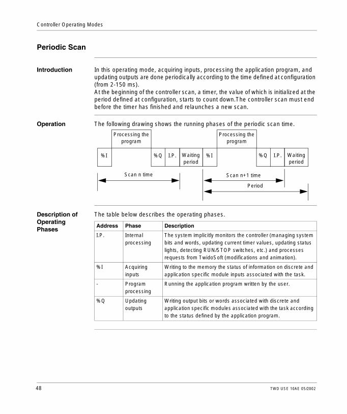
Introduction In this operating mode, acquiring inputs, processing the application program, and updating outputs are done periodically according to the time defined at configuration (from 2-150 ms).At the beginning of the controller scan, a timer, the value of which is initialized at the period defined at configuration, starts to count down.The controller scan must end before the timer has finished and relaunches a new scan.
Operation The following drawing shows the running phases of the periodic scan time.
Description of Operating Phases
The table below describes the operating phases.
Scan n time Scan n+1 time
Processing the program
Waiting period
I.P.%Q I.P.%Q
Processing the program
Waiting period
%I %I
Period
Address Phase Description
I.P. Internal processing
The system implicitly monitors the controller (managing system bits and words, updating current timer values, updating status lights, detecting RUN/STOP switches, etc.) and processes requests from TwidoSoft (modifications and animation).
%I Acquiring inputs
Writing to the memory the status of information on discrete and application specific module inputs associated with the task.
- Program processing
Running the application program written by the user.
%Q Updating outputs
Writing output bits or words associated with discrete and application specific modules associated with the task according to the status defined by the application program.
48 TWD USE 10AE 05/2002

Controller Operating Modes
Operating Mode Controller in RUN, the processor performs:l Internal processing orderl Acquiring inputsl Processing the application programl Updating outputsIf the period has not finished, the processor completes it operating cycle until the end of the internal processing period. If the operating time is longer than that allocated to the period, the controller indicates that the period has been exceeded by setting the task system bit %S19 to 1. The process continues and is run completely (however, it must not exceed the watchdog time limit). The following scan is linked in after writing the outputs of the scan in progress implicitly.Controller in STOP, the processor performs:l Internal processingl Acquiring inputs
TWD USE 10AE 05/2002 49

Controller Operating Modes
Illustration The following illustration shows the operating cycles.
Check Cycle Two checks are carried out:l Period overflowl Watchdog
Internal processing
Acquiring inputs
Updating outputs
Program processing
RUN STOP
Internal processing
Starting the period
End of period
50 TWD USE 10AE 05/2002

Controller Operating Modes
Checking Scan Time
General Points The master task cycle is monitored by a watchdog timer called Tmax (a maximal duration of master task cycle). It permits the showing of application errors (infinite loops, and so on.) and assures a maximal duration for output refreshing.
Software WatchDog (Periodic or Cyclic Operation)
In periodic or cyclic operation, the triggering of the watchdog causes a software error. The application passes into a HALT state and sets bit %S11 to 1. The relaunching of the task necessitates a connection to Twido Soft in order to analyze the cause of the error, modification of the application to correct the error, and relaunching the INIT and RUN requests.
Check on Periodic Operation
In periodic operation an additional check is used to detect the period being exceeded:l %S19 indicates that the period has been exceeded. It is set to:
l 1 by the system when the scan time is greater that the task period.l 0 by the user.
l %SW0 contains the period value (0-150 ms). It is:l Initialized when starting from a cold start by the value set in the configuration.l It can be modified by the user.
Using Master Task Running Time
The following system words are used for information on the controller scan cycle time:l %SW11 initializes to the maximum watchdog time (10 to 500 ms).l %SW30 contains the execution time for the last controller scan cycle.l %SW31 contains the execution time for the longest controller scan cycle since
the last cold start.l %SW32 contains the execution time for the shortest controller scan cycle since
the last cold start.
Note: The HALT state is when the application is stopped immediately because of an application software error such as a scan overrun. The data retains the current values, which allows for an analysis of the cause of the error. The tasks are all stopped on the current instruction. Communication with the controller is available.
Note: This different information can also be accessed from the configuration editor.
TWD USE 10AE 05/2002 51

Controller Operating Modes
Operating Modes
Introduction Twido Soft is used to take into account the three main operating mode groups:l Checkingl Running or productionl Stopping
Starting through Grafcet
These different operating modes can be obtained around or starting from Grafcet using the following methods:l Grafcet initializationl Presetting of stepsl Maintaining a situationl Freezing chartsPreliminary processing and use of system bits ensure effective operating mode management without complicating and overburdening the user program.
Note: These operating modes are defined in the "Design Guide for Operating and Stopping Modes" produced by the Applied Industrial Automation Development Agency.
52 TWD USE 10AE 05/2002

Controller Operating Modes
Grafcet System Bits
Use of bits %S21, %S22 and %S23 is reserved for preliminary processing only. These bits are automatically reset by the system. They must be written by Set Instruction S only.The following table provides Grafcet-related system bits:
Bit Function Description
%S21 GRAFCET initialization Normally set to 0, it is set to 1 by:l A cold restart, %S0=1.l The user, in the pre-processing program part only,
using a Set Instruction S %S21 or a set coil -(S)- %S21.
Consequences:l Deactivation of all active steps.l Activation of all initial steps.
%S22 GRAFCET RESET Normally set to 0, it can only be set to 1 by the program in pre-processing.Consequences:l Deactivation of all active steps.l Scanning of sequential processing stopped.
%S23 Preset and freeze GRAFCET
Normally set to 0, it can only be set to 1 by the program in pre-processing.l Reset Grafcet by setting %S22 to 1.l Preposition the steps to be activated by a series of S
Xi instructions.l Enable prepositioning by setting %S23 to 1.Freezing a situation:l In initial situation: by maintaining %S21 at 1 by
program.l In "empty" situation: by maintaining %S22 at 1 by
program.l In situation determined by maintaining %S23 at 1.
TWD USE 10AE 05/2002 53
Controller Operating Modes
Dealing with Power Cuts and Power Restoration
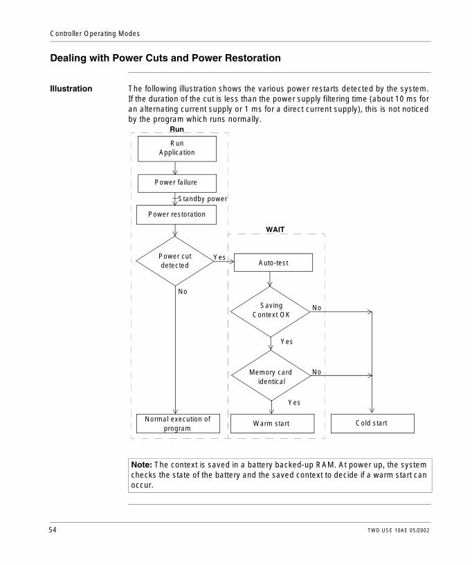
Illustration The following illustration shows the various power restarts detected by the system. If the duration of the cut is less than the power supply filtering time (about 10 ms for an alternating current supply or 1 ms for a direct current supply), this is not noticed by the program which runs normally.
Note: The context is saved in a battery backed-up RAM. At power up, the system checks the state of the battery and the saved context to decide if a warm start can occur.
Power cut detected
RunApplication
Power failure
Power restoration
SavingContext OK
Memory card identical
Normal execution of program
Warm start Cold start
Standby power
No
Yes
Yes
Yes
No
No
Auto-test
WAIT
Run
54 TWD USE 10AE 05/2002

Controller Operating Modes
Run/Stop Input Bit Versus Auto Run
The Run/Stop input bit has priority over the Automatic Start in Run option that is available from the Scan Mode dialog box (see the TwidoSoft Operation Guide). If the Run/Stop bit is set, then the controller will restart in the Run Mode when power is restored. The mode of the controller is determined as follows:
Operation The table below describes the processing phases for power cuts.
Run/Stop Input Bit Auto Start in Run Resulting State
Zero Zero Stopped
Zero One Stopped
Rising edge Don’t care Running
One Don’t care Running
Not configured in software Zero Stopped
Not configured in software One Running
Note: For all Compact type of controllers, if the controller was in Run mode when power was interrupted, and the "Automatic Start in Run" flag was not set from the Scan Mode dialog box, the controller will restart in Stop mode when power is restored.
Note: For all Modular type of controllers, if the battery in the controller is operating normally when power was interrupted, the controller will startup in the mode that was in effect at the time the power was interrupted. The "Automatic Start in Run" flag, that was selected from the Scan Mode dialog, will have no effect on the mode when the power is restored.
Phase Description
1 In the event of a power cut the system stores the application context and the time of the cut.
2 It sets all outputs in a fallback state as a function of the security parameters (%S9).
3 When power is restored, the context saved is compared with the one in progress which defines the type of start to run:l If the application context has changed (loss of system context or new
application), the controller initializes the application: start up from cold,l If the application context is the same, the controller restarts without initializing
data: warm restart.
TWD USE 10AE 05/2002 55

Controller Operating Modes
Dealing with a Warm Restart
Cause of a Warm Restart
A warm-start can occur:l When power is restored without loss of application context,l When bit %S1 is set to state 1 by the program,l From the Operator Display when the controller is in STOP mode.
Illustration The drawing below describes a warm restart operation in RUN mode.
Note: Compact controllers always power-up in cold-start. Modular controllers always restart in warm restart.
Acquisition of inputs
if bit %S1=1, possible process with
warm restart
Set bit %S1 to 0
Execution of programTOP
Update outputs
Stop the processor Save application
context
Restoration of power
Partial configuration auto-tests
Set bit %S1 to 1for only one cycle
WAITRUN
BOT
No
Yes
>Micro power cut
Detection of power cut
56 TWD USE 10AE 05/2002

Controller Operating Modes
Restart of the Program Execution
The table below describes the restart phases for running a program after a warm restart.
Processing of a Warm-Start
In the event of a warm-start, if a particular application process is required, bit %S1 must be tested at the start of the task cycle, and the corresponding program called up.
Outputs after Power Failure
As soon as a power failure is detected, the outputs are set to a fall-back (default) state of 0.When power is restored, outputs are at last state until they are updated again by the task.
Phase Description
1 The program execution resumes from the same element where it was prior to the power cut, without updating the outputs.Note: Only the same element from the user code is restarted. The system code (for example, the updating of outputs) is not restarted.
2 At the end of the restart cycle, the system: l Unreserves the application if it was reserved (and provokes a STOP
application in case of debugging)l Reinitializes the messages
3 The system carries out a restart cycle in which it: l Relaunches the task with bits %S1 (warm-start flag) and %S13 (first cycle in
RUN) set to 1l Resets bits %S1 and %S13 to 0 at the end of the first task cycle
TWD USE 10AE 05/2002 57

Controller Operating Modes
Dealing with a Cold Start
Cause of a Cold Start
A cold-start can occur:l When loading a new application into RAMl when power is restored with loss of application contextl When bit %S0 is set to state 1 by the programl From the Operator Display when the controller is in STOP mode
Illustration The drawing below describes a cold restart operation in RUN mode.
Note: Compact controllers always power-up in cold-start. Modular controllers always restart in warm restart.
>Micro power cut
Acquisition of inputs
if bit %S0=1, possible process with
cold restart
Set bit %S0 to 0
Execution of programTOP
Update outputs
Stop the processor Save application
context
Restoration of power
Completion of configuration auto-tests
Set bit %S0 to 1
Yes
Initialization of application
WAITRUN
BOT
No
Detection of power cut
AUTO-TESTS
58 TWD USE 10AE 05/2002

Controller Operating Modes
Operation The table below describes the restart phases for running a program after a cold restart.
Processing of a Cold-Start
In the event of a cold-start, if a particular application process is required, bit %S0 (which stays at 1) must be tested during the first cycle of the task.
Outputs after Power Failure
As soon as a power failure is detected, the outputs are set to a fall-back (default) state of 0.When power is restored, outputs are at 0 until they are updated again by the task.
Phase Description
1 At start up, the controller is in RUN.At a cold restart after a stop due to an ERROR, the system forces a cold restart.The program execution restarts at the beginning of the cycle.
2 The system: l Resets internal bits and words and the I/O images to 0l Initializes system bits and wordsl Initializes function blocks from configuration data
3 For this first restart cycle, the system: l Relaunches the task with bits %S0 (cold restart flag) and %S13 (first cycle in
RUN) set to 1l Resets bits %S0 and %S13 to 0 at the end of this first task cycle
TWD USE 10AE 05/2002 59

Controller Operating Modes
Initializing the Controller
Introduction The controllers can be initialized by Twido Soft by setting system bits %S0 (a cold restart) and %S1 (a warm restart).
Cold Start Initialization
For a cold start initialization, system bit %S0 must be set to 1.
Warm Start Initialization Using %S0 and %S1
For a warm start initialization, system bit %S1 and %S0 must be set to 1.The following example shows how to program a warm restart initialization using system bits.
Warm Start Initialization Using INIT Command
A warm start initialization can also be requested using an INIT command. The INIT command sends the controller into the IDLE state, and reinitialization of the application data and task state in STOPPED state.
Note: Do not set %S0 to 1 for more than one controller scan.
%S1 %S0
LD %S1 If %S1 = 1 (warm restart), set %S0 to 1 initialize the controller.ST %S0 These two bits are reset to 0 by the system at the end of the
following scan.
60 TWD USE 10AE 05/2002

TWD USE 10AE 05/2002
II
Special FunctionsAt a Glance
Overview This part describes communications, built-in analog functions, and managing analog I/O modules for Twido controllers.
What’s in this Part?
This part contains the following chapters:
Chapter Chapter Name Page
5 Communications 63
6 Built-In Analog Functions 111
7 Managing Analog Modules 115
8 Operator Display Operation 123
61

Special Functions
62 TWD USE 10AE 05/2002

TWD USE 10AE 05/2002
5
CommunicationsAt a Glance
Overview This chapter provides an overview of configuring, programming, and managing communications available with Twido controllers.
What’s in this Chapter?
This chapter contains the following topics:
Topic Page
Communications Overview 64
TwidoSoft to Controller Communications 65
Remote Link Communications 67
ASCII Communications 79
Modbus Communications 90
Standard Modbus Requests 106
63

Communications
Communications Overview
Overview Twido provides one or two serial communications ports used for communications to remote controllers, peer controllers, or general external devices. Either port, if available, can be used for any of the services, with the exception of communicating with Twido Soft, which can only be performed using the first port. Three different base protocols are supported on each Twido controller: Remote Link, ASCII, or Modbus (modbus master or modbus slave).
Remote Link The remote link is a high-speed master/slave bus designed to communicate a small amount of data between the master controller and up to seven remote (slave) controllers. Application or I/O data is transferred, depending on the configuration of the remote controllers. A mixture of remote controller types is possible, where some can be remote I/O and some can be peers.
ASCII The ASCII protocol is a simple half-duplex character mode protocol used to transmit and/or receive a character string to/from a simple device (printer or terminal). This protocol is supported only via the "EXCH" instruction.
Modbus The Modbus protocol is a master/slave protocol that allows for one, and only one, master to request responses from slaves, or to act based on the request. The master can address individual slaves, or can initiate a broadcast message to all slaves. Slaves return a message (response) to queries that are addressed to them individually. Responses are not returned to broadcast queries from the master.Modbus Master - The modbus master mode allows the Twido controller to initiate transmission of a modbus query, with a response expected from a modbus slave. The modbus master mode is only supported via the "EXCH" instruction. Both Modbus ASCII and RTU are supported in modbus master mode.Modbus Slave - The modbus slave mode allows the Twido controller to respond to modbus queries from a modbus master, and is the default communications mode if no communication is configured. The Twido controller supports the standard modbus data and control functions and service extensions for object access. Both Modbus ASCII and RTU are supported in modbus slave mode.
Note: There can be up to 32 nodes on an RS-485 network (1 master and up to 31 slaves), whose addresses can be in the range of 1-247.
64 TWD USE 10AE 05/2002

Communications
TwidoSoft to Controller Communications
Overview Each Twido controller has on its Port 1 a built-in EIA RS-485 terminal port with internal power supply. You must use Port 1 to communicate to the TwidoSoft programming package. No optional cartridge or communication module can be used for this connection.
Cable Connection
The EIA RS-232C Port on your personal computer is connected to the controller’s Port 1 using the TSXPCX1031 multi-function communication cable. This cable converts signals between EIA RS-232 and EIA RS-485. This cable is equipped with a 4-position rotary switch to select different modes of operation. The switch designates the four positions as "0-3", and the appropriate setting for TwidoSoft to Twido controller is location 2.This connection is illustrated in the diagram below.
CAUTION
UNEXPECTED EQUIPMENT DAMAGE
TwidoSoft may not sense a disconnect when physically moving the TSXPCX1031 communication cable from a first controller and quickly inserting it in a second controller. To avoid this condition, use TwidoSoft to disconnect before moving the cable.
Failure to observe this precaution can result in injury or equipment damage.
Note: The DPT signal is not tied to ground. The signal is internally pulled up indicating to the firmware executive that this is a TwidoSoft connection.
1
2
3
0
PC Serial PortEIA RS-232
Port 1RS485 TSXPCX1031
TWD USE 10AE 05/2002 65

Communications
Pin outs of Male and Female Connectors
The following figure shows the pin outs of a male 8-pin miniDIN connector.
The following figure shows the pin outs of a female 9-pin subD connector.
6 8
53
21
4
7
Pin outs1 2 3 4 5 6 7 8
RS-485A (+)B (-)NC/DEDPTNC0 V5 V
Pin outs1 2 3 4 5 6 7 8
RS-232DCDRXTXDTRSGNCRTSCTS
9 NC
1
5
6
9
66 TWD USE 10AE 05/2002

Communications
Remote Link Communications
Introduction The remote link is a high-speed master/slave bus designed to communicate a small amount of data between the master controller and up to seven remote (slave) controllers. Application or I/O data is transferred, depending on the configuration of the remote controllers. A mixture of remote controller types is possible, where some can be remote I/O and some can be peers.
Note: The master controller contains information regarding the address of a remote I/O. It does not know which specific controller is at the address. Therefore, the master can not validate that all the remote inputs and outputs used in the user application actually exist. Take care that these remote inputs or outputs actually exist.
Note: The remote I/O bus and the protocol used is proprietary and no third party devices are allowed on the network.
CAUTION
UNEXPECTED EQUIPMENT OPERATION
l Be sure that there is only one master controller on a remote link and that each slave has a unique address. Failure to observe this precaution may lead to corrupted data or unexpected and ambiguous results.
l Be sure that all slaves have unique addresses. No two slaves should have the same address. Failure to observe this precaution may lead to corrupted data or unexpected and ambiguous results.
Failure to observe this precaution can result in injury or equipment damage.
Note: The remote link requires an EIA RS-485 connection and can only run on one communications port at a time.
TWD USE 10AE 05/2002 67

Communications
Hardware Configuration
Remote link must use a minimum 3-wire EIA RS-485 port. This means that it can be configured to use either the first or an optional second port if present.
The table below lists the devices that can be used:
Note: Only one communication port can be configured as a remote link.
Device Port Characteristics
TWDCAA10/16/24DRF, TWDLMDA20/40DUK, TWDLMDA20/40DTK, TWDLMDA20DRT
1 Base controller supporting a 3-wire EIA RS-485 using a miniDin connector.
TWDNOZ232D 2 Communication module supporting a 3-wire EIA RS-232 using a miniDin connector.Note: This module is only available for the Modular controllers. When the module is attached, the controller cannot have an Operator Display expansion module.
TWDNOZ485D 2 Communication module supporting a 3-wire EIA RS-485 using a miniDin connector.Note: This module is only available for the Modular controllers. When the module is attached, the controller cannot have an Operator Display expansion module.
TWDNOZ485T 2 Communication module supporting a 3-wire EIA RS-485 using a terminal connector.Note: This module is only available for the Modular controllers. When the module is attached, the controller cannot have an Operator Display expansion module.
TWDNAC232D 2 Communication adapter supporting a 3-wire EIA RS-232 using a miniDin connector.Note: This adapter is only available for the Compact 16 and 24 I/O controllers and the Operator Display expansion module.
TWDNAC485D 2 Communication adapter supporting a 3-wire EIA RS-485 using a miniDin connector.Note: This adapter is only available for the Compact 16 and 24 I/O controllers and the Operator Display expansion module.
TWDNAC485T 2 Communication adapter supporting a 3-wire EIA RS-485 using a terminal connector.Note: This adapter is only available for the Compact 16 and 24 I/O controllers and the Operator Display expansion module.
TWDXCPODM 2 Operator Display expansion module supporting either a 3-wire EIA RS-232 using a miniDIN connector, EIA RS-485 using a miniDIN connector, or EIA RS-485 using a terminal connector.Note: This module is only available for the Modular controllers. When the module is attached, the controller cannot have an Communication expansion module.
Note: Port 2 configuration (availability and type) is checked only at power-up or reset.
68 TWD USE 10AE 05/2002

Communications
Cable Connection to Each Device
Cable connections to each device are illustrated below.
Note: The DPT signal on pin 5 must be tied to ground on pin 7 in order to signify the use of remote link communications. When this signal is not tied to ground, the Twido controller as either the master or slave will default to a mode of attempting to establish communications with TwidoSoft.
Note: The DPT to GND connection is only necessary if you are connected to a base controller on Port 1.
A(+) B(-) GND DPT
Master. . .Controller
A(+) B(-) GND DPT
RemoteController
A(+) B(-) GND DPT
RemoteController
TWD USE 10AE 05/2002 69

Communications
Software Configuration
There must be only one master controller defined on the remote link. In addition, each remote controller must maintain a unique slave address. Multiple masters or slaves using identical addresses can either corrupt transmissions or create ambiguity.
Master Controller Configuration
The master controller is configured using TwidoSoft to manage a remote link network of up to seven remote controllers. The master supports a heterogeneous mixture of both remote controllers (either as remote I/O and peer controllers) on the remote link. The address of the master is configured using TwidoSoft to be at address 0.
Remote Controller Configuration
Each of the remote controllers can be used as either a remote I/O or a peer controller. These are configured using TwidoSoft to be assigned address from 1 and 7 (Note that 0 is reserved for the remote link master). The table below summarizes the differences and constraints of each of these types of remote controller configurations:
CAUTION
Unexpected Equipment Operation
Be sure that there is only one master controller on a remote link and that each slave has a unique address. Failure to observe this precaution may lead to corrupted data or unexpected and ambiguous results.
Failure to observe this precaution can result in injury or equipment damage.
Type Application Program Data Access
Remote I/O No
Not even a simple "END" statement
%I and %Q
Only local I/O on the remote controller is accessible. (Not its expansion I/O)
Peer controller Yes
Run mode is not coupled to Master’s
%INW and %QNW
A maximum of 4 words of input and 4 words of output can be transmitted to and from each peer
70 TWD USE 10AE 05/2002

Communications
Remote Controller Scan Synchronization
The update cycle of the remote link is not synchronized with the master controller’s scan. The communications with the remote controllers is interrupt driven and happens as a background task in parallel with the running of the master controller’s scan. At the end of the scan cycle, the most up to date values are read into the application data to be used for the next solve. This processing is the same for remote I/O and peer controllers.Any controller can check for general link activity using system bit %S111. But to achieve synchronization, a master or peer will have to use system bit %S110. This is set to 1 when a complete update cycle has taken place. The application program is responsible to reset this to 0.The master can enable or disable the remote link using system bit %S112. Controllers can check on the proper configuration and health of the remote link using %S113. The DPT signal on Port 1 (used to determine if TwidoSoft is connected) is sensed and reported on %S100. All these are summarized in the following table:
Master Controller Restart
If a master controller restarts, one of the following events happens:l A cold start (%S0 = 1) forces a re-initialization of the communications.l A warm start (%S1 = 1) forces a re-initialization of the communications.l In Stop mode, the master continues communicating with the slaves, with the Run/
Stop bit set to indicate stop.
System Bit State Indication
%S100 0 master/slave: DPT not active (TwidoSoft cable NOT connected)
1 master/slave: DPT active (TwidoSoft cable connected)
%S110 0 master/slave: reset by application
1 master: all remote link exchanges completed (remote I/O only) slave: exchange with master completed
%S111 0 master: single remote link exchange completedslave: single remote link exchange detected
1 master: single remote link exchange activeslave: single remote link exchange detected
%S112 0 master: remote link disabled
1 master: remote link enabled
%S113 0 master/slave: remote link configuration/operation OK
1 master: remote link configuration/operation errorslave: remote link operation error
TWD USE 10AE 05/2002 71

Communications
Slave Controller Restart
If a slave controller restarts, one of the following events happens:l A cold start (%S0 = 1) forces a re-initialization of the communications.l A warm start (%S1 = 1) forces a re-initialization of the communications.l In Stop mode, the slave continues communicating with the master. If the master
indicates a Stop is requested:l The remote I/O affects a Stop,l A peer controller continues in it’s current state.
Remote I/O Data Access
The remote controller configured to be a remote I/O does not have or execute its own application program. The remote controller's base digital inputs and outputs are a simple extension of the master controller's. The application must only use the full three digit addressing mechanism provided.
To communicate with remote I/O, the master controller uses the standard input and output notation of %I and %Q. To access the third output bit of the remote I/O configured at address 2, the master would set %Q2.0.2. Similarly, to read the fifth input bit of the remote I/O configured at location 7, the master would load %I7.0.4.
Note: The module number is always zero for remote I/O.
Note: The master is restricted to accessing only the digital I/O that is part of the remote’s local I/O. No analog or expansion I/O can be transferred, unless you use peer communications.
%Q2.0.2%I7.0.4
Remote Controller AddressModular NumberChannel Number
72 TWD USE 10AE 05/2002

Communications
Remote I/OAddress 2
Remote I/OAddress 4
%I2.0.0
%I2.0.x
%Q2.0.0
%Q2.0.x
%I4.0.0
%I4.0.x
%Q4.0.0 . . .%Q4.0.x
. . .
. . .
. . .
%I0.0.0
%I0.0.x
%Q0.0.0
%Q0.0.x
. . .
. . .
%I0.0.0
%I0.0.x
%Q0.0.0
%Q0.0.x
. . .
. . .
Remote Link
Master ControllerAddress 0
TWD USE 10AE 05/2002 73

Communications
Peer Controller Data Access
To communicate with peer controllers, the master uses network words %INW and %QNW to exchange data. Each peer on the network is accessed by its remote address "j" using words %INWj.k and %QNWj.k. Each peer controller on the network uses %INW0.0 to %INW0.3 and %QNW0.0 to %QNW0.3 to access data on the master. Network words are updated automatically when the controllers are in RUN or STOPPED mode.The example below illustrates the exchange of a master with two configured peer controllers.
There is no peer-to-peer messaging within the remote link. Application programs can be used in conjunction with the network words, to transfer information between the remote controllers, in effect using the master as a bridge.
Peer ControllerAddress 3
Peer ControllerAddress 1
%INW1.0
%INW1.x
%QNW1.0
%QNW1.X
%INW3.0
%INW3.X
. . .
. . .
. . .
%QNW0.0
%QNW0.x
%INW0.0
%IWN0.x
. . .
. . .
Remote Link
%QNW0.0
%QNW0.x
%INW0.0
%INW0.X
. . .
. . .%INW3.0
%INW3.X . . .
Master ControllerAddress 0
74 TWD USE 10AE 05/2002

Communications
Status Information
In addition to the system bits explained earlier, the master maintains status on the presence and configuration of remote controllers. This is done in system words %SW111 and %SW113. Either the remote or the master can acquire the value of the last error that occurred while communicating on the remote link in system word %SW112. Each of these is detailed in the following table:
System Words
Use
%SW111 Remote Link status: two bits for each remote controller (master only)
x0-5 0 - Remote controller 1-6 not present
1 - Remote controller 1-6 present
x6 0 - Remote controller 7 not present
1 - Remote controller 7 present
x8-13 0 - Remote I/O detected at remote controller 1-6
1 - Peer controller detected at remote controller 1-6
x14 0 - Remote I/O detected at remote controller 7
1 - Peer controller detected at remote controller 7
%SW112 Remote Link configuration/operation error code:
0 - operations are successful
1 - timeout detected (slave)
2 - checksum error detected (slave)
3 - configuration mismatch (slave)
%SW113 Remote Link configuration: two bits for each remote controller (master only)
x0-5 0 - Remote controller 1-6 not configured
1 - Remote controller 1-6 configured
x6 0 - Remote controller 7 not configured
1 - Remote controller 7 configured
x8-13 0 - Remote I/O configured as remote controller 1-6
1 - Peer controller configured as remote controller 1-6
x14 0 - Remote I/O configured as remote controller 7
1 - Peer controller configured as remote controller 7
TWD USE 10AE 05/2002 75

Communications
Remote Link Example
To configure a Remote Link, you must:1. Configure the hardware.2. Connect the controller cabling.3. Connect the communications cable between the PC to the controllers.4. Configure the software.5. Write an application.The diagrams below illustrate the use of the remote link with remote I/O and a peer controller.Step 1: Configure the Hardware:
The hardware configuration is three base controllers of any type. Port 1 is used in a dual mode. One mode is to configure and transfer the application program with TwidoSoft. The second mode is for the Remote Link network. If available, an optional Port 2 on any of the controllers can be used, but a controller only supports a single Remote Link.
Step 2: Connect the Controller Cabling:
Connect the D(+) and D(-) signal wires together. And at each controller, the DPT signal is tied to ground. Although tying the signal to ground is not required for use with a remote link on Port 2 (optional cartridge or communication module), it is good practice.
Note: In this example the first two inputs on the Remote I/O are hard wired to its outputs.
Peer Controller
I0.0
I0.1
Q0.0
Q0.1
Master Controller Remote I/O
A(+) B(-) GND DPT
Master. . .Controller
A(+) B(-) GND DPT
Remote ControllerAddress 1
A(+) B(-) GND DPT
Peer ControllerAddress 2
76 TWD USE 10AE 05/2002

Communications
Step 3: Connect the Communications Cable between the PC and Controllers:
The TSXPCX1031 multi-function programming cable is used to communicate with each of the three base controllers. Be sure that the cable is on switch position 2. In order to program each of the controllers, a point-to-point communication with each controller will need to be to established. To establish this communication: connect to Port 1 of the first controller, transfer the configuration and application data, and set the controller to the run state. Repeat this procedure for each controller.
Once all three controllers are programmed, connect the controllers on the Remote Link network as described in Step 2. Step 4: Configure the Software:
Each of the three controllers uses TwidoSoft to create a configuration, and if appropriate, the application program. For the master controller, edit the controller communication setup to set the protocol to "Remote Link" and the Address to "0 (Master)".
In TwidoSoft, add a "Remote I/O" at address "1" and a "Peer controller" at address "2". For the controller configured as a remote I/O, verify that the controller communication setup is set to "Remote Link" and the address is set to "1". For the controller configured as peer, verify that the controller communication setup is set to "Remote Link" and the address is set to "2".
Note: The cable needs to be moved after each controller configuration and application transfer.
Note: Only one controller can be configured as the master on a Remote Link.
1
2
3
0
Master Controller Peer ControllerRemote I/O TSXPCX1031PC Serial PortEIA RS-232
Controller Comm Setup Type: Remote Link
Address: 0 (Master)
Add Remote Controllers Controller Usage: Remote I/O
Remote Address: 1
Controller Usage: PeerRemote Address: 2
Controller Comm Setup Type: Remote Link
Address: 1
Controller Comm Setup Type: Remote Link
Address: 2
TWD USE 10AE 05/2002 77

Communications
Step 5: Write an Application:
In this example, master application increments an internal memory word and communicates this to the peer controller using a single network word. The peer controller takes the word received from the master and echoes it back. In the master, a different memory word receives and stores this transmission. For communication with the remote I/O controller, the master sends its local inputs to the remote I/O’s outputs. With the external I/O hard wiring of the remote I/O, the signals are returned and retrieved by the master.
Note: This communication takes place under the master’s application. There is no application in the remote I/O controller.
LD 1[%QNW0.0 := %INW0.0]
LD 1
[%MW0 := %MW0 +1][%QNW2.0 := %MW0][%MW1 := %INW2.0]
LD %I0.0ST %Q1.0.0LD %I1.0.0ST %Q0.0
LD %I0.1ST %Q1.0.1LD %I1.0.1ST %Q0.1
78 TWD USE 10AE 05/2002

Communications
ASCII Communications
Introduction ASCII protocol provides Twido controllers a simple half-duplex character mode protocol to transmit and/or receive data with a simple device. This protocol is supported using the EXCHx instruction and controlled using the %MSGx function block. Three types of communications are possible with the ASCII Protocol:l Transmission Onlyl Transmission/Receptionl Reception OnlyThe maximum size of frames transmitted and/or received using the EXCHx instruction is 128 bytes.
TWD USE 10AE 05/2002 79

Communications
Hardware Configuration
An ASCII link can be established on either the EIA RS-232 or EIA RS-485 port and can run on as many as two communications ports at a time.The table below lists the devices that can be used:
Device Port Characteristics
TWDCAA10/16/24DRF, TWDLMDA20/40DUK, TWDLMDA20/40DTK, TWDLMDA20DRT
1 Base controller supporting a 3-wire EIA RS-485 using a miniDin connector.
TWDNOZ232D 2 Communication module supporting a 3-wire EIA RS-232 using a miniDin connector.Note: This module is only available for the Modular controllers. When the module is attached, the controller cannot have an Operator Display expansion module.
TWDNOZ485D 2 Communication module supporting a 3-wire EIA RS-485 using a miniDin connector.Note: This module is only available for the Modular controllers. When the module is attached, the controller cannot have an Operator Display expansion module.
TWDNOZ485T 2 Communication module supporting a 3-wire EIA RS-485 using a terminal connector.Note: This module is only available for the Modular controllers. When the module is attached, the controller cannot have an Operator Display expansion module.
TWDNAC232D 2 Communication adapter supporting a 3-wire EIA RS-232 using a miniDin connector.Note: This adapter is only available for the Compact 16 and 24 I/O controllers and the Operator Display expansion module.
TWDNAC485D 2 Communication adapter supporting a 3-wire EIA RS-485 using a miniDin connector.Note: This adapter is only available for the Compact 16 and 24 I/O controllers and the Operator Display expansion module.
TWDNAC485T 2 Communication adapter supporting a 3-wire EIA RS-485 using a terminal connector.Note: This adapter is only available for the Compact 16 and 24 I/O controllers and the Operator Display expansion module.
TWDXCPODM 2 Operator Display expansion module supporting a 3-wire EIA RS-232 using a miniDIN connector, EIA RS-485 using a miniDIN connector, or EIA RS-485 using a terminal connector.Note: This module is only available for the Modular controllers. When the module is attached, the controller cannot have an Communication expansion module.
Note: Port 2 configuration (availability and type) is checked only at power-up or reset by the firmware executive.
80 TWD USE 10AE 05/2002
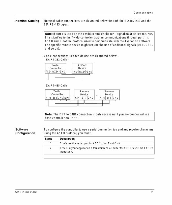
Communications
Nominal Cabling Nominal cable connections are illustrated below for both the EIA RS-232 and the EIA RS-485 types.
Cable connections to each device are illustrated below.
Software Configuration
To configure the controller to use a serial connection to send and receive characters using the ASCII protocol, you must:
Note: If port 1 is used on the Twido controller, the DPT signal must be tied to GND. This signifies to the Twido controller that the communications through port 1 is ASCII and is not the protocol used to communicate with the TwidoSoft software. The specific remote device might require the use of additional signals (DTR, DSR, and so on).
Note: The DPT to GND connection is only necessary if you are connected to a base controller on Port 1.
TXD RXD GND
TwidoController
EIA RS-232 Cable
TXD RXD GND
RemoteDevice
A(+) B(-) GND DPT
TwidoController
EIA RS-485 Cable
A(+) B(-) GND
RemoteDevice ...
A(+) B(-) GND
RemoteDevice
Stage Description
1 Configure the serial port for ASCII using TwidoSoft.
2 Create in your application a transmit/receive buffer for ASCII to use the EXCHx instruction.
TWD USE 10AE 05/2002 81
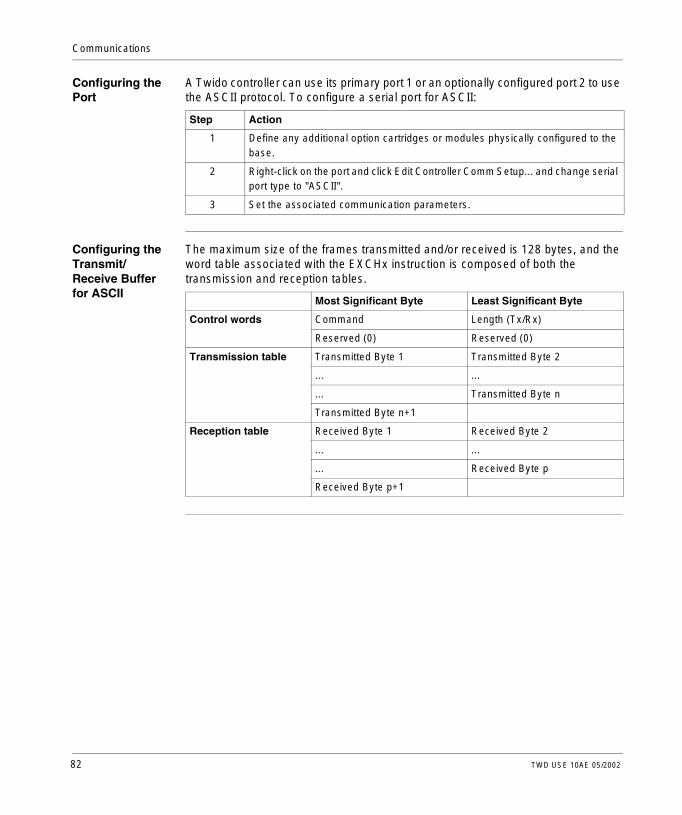
Communications
Configuring the Port
A Twido controller can use its primary port 1 or an optionally configured port 2 to use the ASCII protocol. To configure a serial port for ASCII:
Configuring the Transmit/Receive Buffer for ASCII
The maximum size of the frames transmitted and/or received is 128 bytes, and the word table associated with the EXCHx instruction is composed of both the transmission and reception tables.
Step Action
1 Define any additional option cartridges or modules physically configured to the base.
2 Right-click on the port and click Edit Controller Comm Setup... and change serial port type to "ASCII".
3 Set the associated communication parameters.
Most Significant Byte Least Significant Byte
Control words Command Length (Tx/Rx)
Reserved (0) Reserved (0)
Transmission table Transmitted Byte 1 Transmitted Byte 2
... ...
... Transmitted Byte n
Transmitted Byte n+1
Reception table Received Byte 1 Received Byte 2
... ...
... Received Byte p
Received Byte p+1
82 TWD USE 10AE 05/2002

Communications
Control Parameters
The Length byte contains the length to be transmitted, which is overwritten by the number of characters received at the end of the reception, if reception is requested.The Command byte must contain one of the following:l 0: Transmission Onlyl 1: Transmission/Receptionl 2: Reception Only
Transmission/Reception Tables
When in Transmit Only mode, the Control and Transmission tables are filled in prior to executing the EXCHx instruction, and can be of type %KW or %MW. No space is required for the reception of characters in Transmission Only mode. Once all bytes are transmitted, the state of %MSGx.D is set to 1, and a new EXCHx instruction can be executed.When in Transmission/Reception mode, the Control and Transmission tables are filled in prior to executing the EXCHx instruction, and must be of type %MW. Space for up to 128 reception bytes is required at the end of the Transmission table. Once all bytes are transmitted, the Twido controller switches to reception mode and waits to receive any bytes.When in Reception Only mode, the Control table is filled in prior to executing the EXCHx instruction, and must be of type %MW. Space for up to 128 reception bytes is required at the end of the Control table. The Twido controller immediately enters the reception mode and waits to receive any bytes.Reception ends when the end-of-frame byte is received, or the Reception table is full. If a non-zero time out is configured, reception ends when the time out is completed. If a zero time out value is selected, there is no reception time out; therefore to stop reception, the %MSGx.R input must be activated.There is no inherent addressing associated with the ASCII protocol, unless the simple device has it built into the protocol, but the Twido controller does not support it.
Message Exchange
The Twido controller can be configured to send and/or receive messages in character mode. The language offers two services for this: l EXCHx instruction: to transmit/receive messagesl %MSGx function block: to control the message exchanges.The Twido controller uses the protocol configured for that port when processing an EXCHx instruction.
Note: Each communications port can be configured for different protocols or the same. The EXCHx instruction or %MSGx function block for each communications port is accessed by appending the port number (1 or 2).
TWD USE 10AE 05/2002 83

Communications
EXCHx Instruction
The EXCHx instruction allows the Twido controller to send and/or receive information to/from ASCII devices. The user defines a table of words (%MWi:L or %KWi:L) containing control information and the data to be sent and/or received (up to 64 data words in transmission and/or reception). The format for the word table is described earlier.A message exchange is performed using the EXCHx instruction:
The Twido controller must finish the exchange from the first EXCHx instruction before a second can be launched. The %MSGx function block must be used when sending several messages.The processing of the EXCHx list instruction occurs immediately, with any transmissions started under interrupt control (reception of data is also under interrupt control), which is considered background processing.
Syntax: [EXCHx %MWi:L] or [EXCHx %KWi:L]
where: x = port number (1 or 2)
L = number of words in the word table
84 TWD USE 10AE 05/2002

Communications
%MSGx Function Block
The use of the %MSGx function block is optional; it can be used to manage data exchanges. The %MSGx function block has three purposes:l Communications error checking
The error checking verifies that the block length (word table) programmed with the EXCHx instruction is large enough to contain the length of the message to be sent. This is compared with the length programmed in the least significant byte of the first word of the word table).
l Coordination of multiple messagesTo ensure the coordination when sending multiple messages, the %MSGx function block provides the information required to determine when a previous message is complete.
l Transmission of priority messagesThe %MSGx function block allows the current message transmission to be stopped, in order to allow the immediate sending of an urgent message.
The %MSGx function block has one input and two outputs associated with it:
Limitations It is important to note the following limitations:l Port 2 availability and type is checked only at power-up or resetl Any message processing on Port 1 is aborted when the TwidoSoft is connectedl EXCHx or %MSG can not be processed on a port configured as Remote Linkl EXCHx aborts active Modbus Slave processing (except for TwidoSoft
processing)l Processing of EXCHx instructions is not re-tried in the event of an errorl R %MSGx can be used to abort EXCHx instruction reception processingl EXCHx instructions can be configured with a time out to abort receptionl Multiple messages are controlled via %MSGx.D
Input/Output Definition Description
R Reset input Set to 1: re-initializes communication or resets block (%MSGx.E = 0 and %MSGx.D = 1).
%MSGx.D Communication complete
0: Request in progress.1: communication done if end of transmission, end character received, error, or reset of block.
%MSGx.E Error 0: Message length OK and link OK.1: if bad command, table incorrectly configured, incorrect character received (speed, parity, and so on.), or reception table full.
TWD USE 10AE 05/2002 85

Communications
Error and Operating Mode Conditions
If an error occurs when using the EXCHx instruction, bits %MSGx.D and %MSGx.E are set to 1 and system word %SW63 contains the error code for Port 1, and %SW64 contains the error code for Port 2.
Master/Slave Controller Restart
If a master/slave controller restarts, one of the following events happens:l A cold start (%S0 = 1) forces a re-initialization of the communications.l A warm start (%S1 = 1) forces a re-initialization of the communications.l In Stop mode, the controller stops all ASCII communications.
System Words Use
%SW63 EXCH1 error code:0 - operation was successful1 - transmission buffer too large (> 128)2 - transmission buffer too small3 - word table too small4 - receive table overflowed5 - time-out elapsed6 - transmission error (received error in response)7 - bad command within table8 - selected port not configured/available9 - reception error10 - can not use %KW if receiving11 - transmission offset larger than transmission table12 - reception offset larger than reception table13 - controller stopped EXCH processing
%SW64 EXCH2 error code. See %SW63.
86 TWD USE 10AE 05/2002

Communications
ASCII Link Example
To configure a ASCII Link, you must:1. Configure the hardware.2. Connect the ASCII communications cable.3. Configure the port.4. Write an application.5. Initialize the Animation Table Editor.The diagram below illustrates the use of the ASCII communications with a Terminal Emulator on a PC.Step 1: Configure the Hardware:
The hardware configuration is two serial connections from the PC to a Twido controller with an optional EIA RS-232 Port 2. On a Modular controller, the optional Port 2 is a TWDNOZ232D. On the Compact controller, the optional Port 2 is a TWDNAC232D. To configure the controller, connect the TSXPCX1031 cable (not shown) to Port 1 of the Twido controller. Next, connect the cable to the COM 1 port on the PC. Be sure that the switch is in position 2. Finally, connect the COM 2 port of the PC to the optional EIA RS-232 Port 2 on the Twido controller. Pin connections and wiring are provided in the next step.Step 2: Connect the ASCII Communications Cable (EIA RS-232):
The minimum requirement for the wiring of the ASCII communications cable is a basic 3-wire connection. Cross the transmit and receive signals.
Note: On the PC side of the cable, additional connections (such as Data Terminal Ready and Data Set Ready) may be needed to satisfy the handshaking. No additional connections are required to satisfy the Twido controller.
Serial COM 2Port 2 EIA RS-232Twido
Controller
TXD RXD GNDTXD RXD GND
TwidoController
PersonalComputer
TWD USE 10AE 05/2002 87

Communications
Step 3: Configure the Port:
Use a simple Terminal Emulator application on the PC to configure a basic port configuration and to ensure that there is no flow control. Use TwidoSoft to configure the controller’s port. First, the hardware option is configured. In this example, the TWDNOZ232D is added to the Modular base controller.Second, the Controller Communication Setup is initialized with all of the same parameter settings as the Terminal Emulator on the PC. In this example, capital letter "A" is chosen for the "End of Frame" character, to terminate the input receive buffer. A 10 second time out for the "Response Timeout" parameter is chosen. Only one of these two parameters will be invoked, depending on whichever one happens first.Step 4: Write an Application:
Use TwidoSoft to create an application program with three primary parts. First, initialize the control and transfer buffer to use for the EXCH instruction. In this example, a command is set up to both send and receive data. The amount of data to send is set to 4 bytes and is initialized to the characters: "O", "K", CR, LF.Next, check the Done bit associated with %MSG2 and issue the EXCH2 instruction only if the port is ready. For the EXCH2 instruction, a value of 8 characters is specified. There are 2 control words (%MW10 and %MW11), 2 words to be used for transmit information (%MW12 and %MW13), and 4 words to receive data (%MW14 through %MW17).
Data: 8 BitParity: NoneStop: 1 BitEnd of Frame: 65
Port: 2Type: ASCIIBaud rate: 19200
Terminal Emulator on a PC
Port: COM2Baud rate: 19200Data: 8 BitParity: NoneStop: 1 BitFlow Control: None
Hardware -> Add OptionTWDNOZ232D
Hardware => Controller Comm. Setup
Response Timeout: 100 x 100 ms
LD 1[%MW10 := 16#0104 ][%MW11 := 16#0000 ][%MW12 := 16#4F4B ][%MW13 := 16#0A0D ]LD 1AND %MSG2.D[EXCH2 %MW10:8]LD %MSG2.EST %Q0.0END
88 TWD USE 10AE 05/2002

Communications
Finally, the error status of the %MSG2 is sensed and stored on the first output bit on the local base controller I/O. Additional error checking using %SW64 could also be added to make this more robust.Step 5: Initialize the Animation Table Editor:
The final step is to download this application controller and run it. Initialize an Animation Table Editor to animate and display the %MW10 through %MW17 words. On the Terminal Emulator, the characters "O"-"K"-CR-LF are displayed. There may be many of these depending on the number of times the EXCH block times out and a new one is issued. On the Terminal Emulator, type "T"-"W"-"I"-"D"-"O"-" "-"A". This is exchanged with the Twido controller and displayed in the Animation Table Editor.
Address Current Retained Format1 %MW10 0104 0000 Hexadecimal2 %MW11 0000 0000 Hexadecimal3 %MW12 4F4B 0000 Hexadecimal4 %MW13 0A0D 0000 Hexadecimal5 %MW14 TW 0000 ASCII6 %MW15 ID 0000 ASCII7 %MW16 O 0000 ASCII8 %MW17 A 0000 ASCII
TWD USE 10AE 05/2002 89

Communications
Modbus Communications
Introduction The Modbus protocol is a master-slave protocol that allows for one, and only one, master to request responses from slaves, or to act based on the request. The master can address individual slaves, or can initiate a broadcast message to all slaves. Slaves return a message (response) to queries that are addressed to them individually. Responses are not returned to broadcast queries from the master.
90 TWD USE 10AE 05/2002

Communications
Hardware Configuration
A Modbus link can be established on either the EIA RS-232 or EIA RS-485 port and can run on as many as two communications ports at a time.The table below lists the devices that can be used:
Device Port Characteristics
TWDCAA10/16/24DRF, TWDLMDA20/40DUK, TWDLMDA20/40DTK, TWDLMDA20DRT
1 Base controller supporting a 3-wire EIA RS-485 using a miniDin connector.
TWDNOZ232D 2 Communication module supporting a 3-wire EIA RS-232 using a miniDin connector.Note: This module is only available for the Modular controllers. When the module is attached, the controller cannot have an Operator Display expansion module.
TWDNOZ485D 2 Communication module supporting a 3-wire EIA RS-485 using a miniDin connector.Note: This module is only available for the Modular controllers. When the module is attached, the controller cannot have an Operator Display expansion module.
TWDNOZ485T 2 Communication module supporting a 3-wire EIA RS-485 using a terminal connector.Note: This module is only available for the Modular controllers. When the module is attached, the controller cannot have an Operator Display expansion module.
TWDNAC232D 2 Communication adapter supporting a 3-wire EIA RS-232 using a miniDin connector.Note: This adapter is only available for the Compact 16 and 24 I/O controllers and the Operator Display expansion module.
TWDNAC485D 2 Communication adapter supporting a 3-wire EIA RS-485 using a miniDin connector.Note: This adapter is only available for the Compact 16 and 24 I/O controllers and the Operator Display expansion module.
TWDNAC485T 2 Communication adapter supporting a 3-wire EIA RS-485 using a terminal connector.Note: This adapter is only available for the Compact 16 and 24 I/O controllers and the Operator Display expansion module.
TWDXCPODM 2 Operator Display expansion module supporting a 3-wire EIA RS-232 using a miniDIN connector, EIA RS-485 using a miniDIN connector, or EIA RS-485 using a terminal connector.Note: This module is only available for the Modular controllers. When the module is attached, the controller cannot have an Communication expansion module.
Note: Port 2 configuration (availability and type) is checked only at power-up or reset by the firmware executive.
TWD USE 10AE 05/2002 91

Communications
Nominal Cabling Nominal cable connections are illustrated below for both the EIA RS-232 and the EIA RS-485 types.
Cable connections to each device are illustrated below.
Software Configuration
To configure the controller to use a serial connection to send and receive characters using the Modbus protocol, you must:
Note: If port 1 is used on the Twido controller, the DPT signal must be tied to GND. This signifies to the Twido controller that the communications through port 1 is Modbus and is not the protocol used to communicate with the TwidoSoft software. The specific remote device might require the use of additional signals (DTR, DSR, and so on).
Note: The DPT to GND connection is only necessary if you are connected to a base controller on Port 1.
TXD RXD GND
TwidoController
EIA RS-232 Cable
TXD RXD GND
RemoteDevice
A(+) B(-) GND DPT
TwidoController
EIA RS-485 Cable
A(+) B(-) GND
RemoteDevice ...
A(+) B(-) GND
RemoteDevice
Stage Description
1 Configure the serial port for Modbus using TwidoSoft.
2 Create in your application a transmit/receive buffer for Modbus to use the EXCHx instruction.
92 TWD USE 10AE 05/2002

Communications
Configuring the Port
A Twido controller can use its primary port 1 or an optionally configured port 2 to use the Modbus protocol. To configure a serial port for Modbus:
Modbus Master Modbus master mode allows the controller to initiate transmission of a Modbus query, with a response expected from a Modbus slave. The Modbus Master mode is only supported via the EXCHx instruction. Both Modbus ASCII and RTU are supported in Modbus Master mode.The maximum size of the frames transmitted and/or received is 128 bytes, and the word table associated with the EXCHx instruction is composed of transmission and reception tables.
Step Action
1 Define any additional option cartridges or modules physically configured to the base.
2 Right-click on the port and click Edit Controller Comm Setup... and change serial port type to "Modbus".
3 Set the associated communication parameters.
Most Significant Byte Least Significant Byte
Control words Command Length (Tx/Rx)
Rx Offset Tx Offset
Transmission table Transmitted Byte 1 Transmitted Byte 2
... ...
... Transmitted Byte n
Transmitted Byte n+1
Reception table Received Byte 1 Received Byte 2
... ...
... Received Byte p
Received Byte p+1
TWD USE 10AE 05/2002 93

Communications
Control Parameters
The Length byte contains the length to transmit, which is overwritten by the number of characters received at the end of the reception, if reception is requested.This parameter is the length in bytes of the transmission table. If the Tx Offset parameter is equal to 0, this parameter will be equal to the frame length itself minus the 2 CRC bytes. If the Tx Offset parameter is not equal to 0, one byte of the buffer (indicated by the offset value) will not be transmitted and this parameter is equal to the frame length itself plus 1.The Command byte in case of Modbus RTU request (except for broadcast) must always equal to 1 (Tx and Rx).The Tx Offset byte contains the offset (1 for the first byte, 2 for the second byte, and so on.) within the Transmission Table to ignore when transmitting the packet. This is used to handle the issues associated with byte/word values within the Modbus protocol. For example, if this byte contains 3, the third byte would be ignored, making the fourth byte in the table the third byte to be transmitted.The Rx Offset byte contains the offset (1 for the first byte, 2 for the second byte, and so on.) within the Reception Table to add when transmitting the packet. This is used to handle the issues associated with byte/word values within the Modbus protocol. For example, if this byte contains 3, the third byte within the table would be filled with a ZERO, and the third byte was actually received would be entered into the fourth location in the table.
94 TWD USE 10AE 05/2002

Communications
Transmission/Reception Tables
When using either mode (Modbus ASCII or Modbus RTU), the Transmission table is filled with the request prior to executing the EXCHx instruction. At execution time, the controller determines what the Data Link Layer is, and performs all conversions necessary to process the transmission and response. Start, end, and check characters are not stored in the Transmission/Reception tables.Once all bytes are transmitted, the controller switches to reception mode and waits to receive any bytes. Reception is completed in one of several ways: end-of-frame character received in ASCII mode; time out on a character or frame has been detected; the Reception table is full.The Transmitted Byte X entries contain Modbus protocol (RTU encoding) data that is to be transmitted. If the communications port is configured for Modbus ASCII, the correct framing characters are appended to the transmission. The first byte contains the device address (specific or broadcast), the second byte contains the function code, and the rest contain the information associated with that function code.
The Received Byte X entries contain Modbus protocol (RTU encoding) data that is to be received. If the communications port is configured for Modbus ASCII, the correct framing characters are removed from the response. The first byte contains the device address, the second byte contains the function code (or response code), and the rest contain the information associated with that function code.
Note: This is a typical application, but does not define all the possibilities. No validation of the data being transmitted will be performed.
Note: This is a typical application, but does not define all the possibilities. No validation of the data being received will be performed, except for checksum verification.
TWD USE 10AE 05/2002 95

Communications
Modbus Slave Modbus slave mode allows the controller to respond to Modbus queries from a Modbus master. The controller supports the standard Modbus Data and Control functions, and UMAS extensions for configuration and object access.When the TSXPCX1031 cable is attached to the controller, Modbus Slave mode communications is started at the port, temporarily disabling the communications mode that was running prior to the cable being connected.The Modbus protocol supports two Data Link Layer formats: ASCII and RTU. Each is defined by the Physical Layer implementation, with ASCII using 7 data bits, and RTU using 8 data bits.When using Modbus ASCII mode, each byte in the message is sent as two ASCII characters. The Modbus ASCII frame begins with a start character (’:’), and ends with two end characters (CR and LF). The end-of-frame character defaults to 0x0A (line feed), and the user can modify the value of this byte during configuration. The check value for the Modbus ASCII frame is a simple two’s complement of the frame, excluding the start and end characters.Modbus RTU mode does not reformat the message prior to transmitting; however, it uses a different checksum calculation mode, specified as a CRC.The Modbus Data Link Layer has the following limitations:l Address 1-247l Bits: 128 bits on request using Modbus open requestsl Words: 64 words of 16 bits on request using Modbus open requests
Message Exchange
The Twido controller can be configured to send and/or receive messages in character mode. The language offers two services for this: l EXCHx instruction: to transmit/receive messagesl %MSGx function block: to control the message exchanges.The Twido controller uses the protocol configured for that port when processing an EXCHx instruction.
Note: Each communications port can be configured for different protocols or the same. The EXCHx instruction or %MSGx function block for each communications port is accessed by appending the port number (1 or 2).
96 TWD USE 10AE 05/2002

Communications
EXCHx Instruction
The EXCHx instruction allows the Twido controller to send and/or receive information to/from Modbus devices. The user defines a table of words (%MWi:L or %KWi:L) containing control information and the data to be sent and/or received (up to 64 data words in transmission and/or reception). The format for the word table is described earlier.A message exchange is performed using the EXCHx instruction:
The Twido controller must finish the exchange from the first EXCHx instruction before a second can be launched. The %MSGx function block must be used when sending several messages.The processing of the EXCHx list instruction occurs immediately, with any transmissions started under interrupt control (reception of data is also under interrupt control), which is considered background processing.
Syntax: [EXCHx %MWi:L] or [EXCHx %KWi:L]
where: x = port number (1 or 2)
L = number of words in the word table
TWD USE 10AE 05/2002 97

Communications
%MSGx Function Block
The use of the %MSGx function block is optional; it can be used to manage data exchanges. The %MSGx function block has three purposes:l Communications error checking
The error checking verifies that the block length (word table) programmed with the EXCHx instruction is large enough to contain the length of the message to be sent. This is compared with the length programmed in the least significant byte of the first word of the word table).
l Coordination of multiple messagesTo ensure the coordination when sending multiple messages, the %MSGx function block provides the information required to determine when a previous message is complete.
l Transmission of priority messagesThe %MSGx function block allows the current message transmission to be stopped, in order to allow the immediate sending of an urgent message.
The %MSGx function block has one input and two outputs associated with it:
Limitations It is important to note the following limitations:l Port 2 availability and type is checked only at power-up or resetl Any message processing on Port 1 is aborted when the TwidoSoft is connectedl EXCHx or %MSG can not be processed on a port configured as Remote Linkl EXCHx aborts active Modbus Slave processing (except for TwidoSoft
processing)l Processing of EXCHx instructions is not re-tried in the event of an errorl R %MSGx can be used to abort EXCHx instruction reception processingl EXCHx instructions can be configured with a time out to abort receptionl Multiple messages are controlled via %MSGx.D
Input/Output Definition Description
R Reset input Set to 1: re-initializes communication or resets block (%MSGx.E = 0 and %MSGx.D = 1).
%MSGx.D Communication complete
0: Request in progress.1: communication done if end of transmission, end character received, error, or reset of block.
%MSGx.E Error 0: Message length OK and link OK.1: if bad command, table incorrectly configured, incorrect character received (speed, parity, and so on.), or reception table full.
98 TWD USE 10AE 05/2002

Communications
Error and Operating Mode Conditions
If an error occurs when using the EXCHx instruction, bits %MSGx.D and %MSGx.E are set to 1 and system word %SW63 contains the error code for Port 1, and %SW64 contains the error code for Port 2.
Master Controller Restart
If a master/slave controller restarts, one of the following events happens:l A cold start (%S0 = 1) forces a re-initialization of the communications.l A warm start (%S1 = 1) forces a re-initialization of the communications.l In Stop mode, the controller stops all Modbus communications.
System Words Use
%SW63 EXCH1 error code:0 - operation was successful1 - transmission buffer too large (> 128)2 - transmission buffer too small3 - word table too small4 - receive table overflowed5 - time-out elapsed6 - transmission error (received error in response)7 - bad command within table8 - selected port not configured/available9 - reception error10 - can not use %KW if receiving11 - transmission offset larger than transmission table12 - reception offset larger than reception table13 - controller stopped EXCH processing
%SW64 EXCH2 error code. See %SW63.
TWD USE 10AE 05/2002 99

Communications
Modbus Link Example 1
To configure a Modbus Link, you must:1. Configure the hardware.2. Connect the Modbus communications cable.3. Configure the port.4. Write an application.5. Initialize the Animation Table Editor.The diagrams below illustrate the use of Modbus function code 3 to read a slave’s output words. This example uses two Twido controllers.Step 1: Configure the Hardware:
The hardware configuration is two Twido controllers. One will be configured as the Modbus Master and the other as the Modbus Slave.
To configure each controller, connect the TSXPCX1031 cable to Port 1 of the first controller.
Next, connect the cable to the COM 1 port of the PC. Be sure that the switch is in position 2. Download and monitor each application. Repeat procedure for second controller.
Note: In this example, each controller is configured to use EIA RS-485 on Port 1 and an optional EIA RS-485 Port 2. On a Modular controller, the optional Port 2 can be either a TWDNOZ485D or a TWDNOZ485T. On a Compact controller, the optional Port 2 can be either a TWDNAC485D or a TWDNAC485T.
Note: The TSXPCX1031 cable can only be connected to one controller at a time, on the EIA RS-485 Port 1 only.
To Serial COM 1
1
2
30
Port 1 EIA RS-485Controller 1ModbusMaster
Controller 2ModbusSlave
Port 1 EIA RS-485
TSXPCX1031
Port 2 EIA RS-485
Port 2 EIA RS-485
100 TWD USE 10AE 05/2002

Communications
Step 2: Connect the Modbus Communications Cable:
The wiring in this example demonstrates a simple point to point connection. The three signals A(+), B(-), and GND signals are wired according to the diagram.If using Port 1 of the Twido controller, the DPT signal must be tied to ground This conditioning of DPT determines if TwidoSoft is connected. When tied to ground, the controller will use the port configuration set in the application to determine the type of communication.Step 3: Configure the Port:
In both the master and slave applications, the optional EIA RS-485 ports are configured. Be sure to change the controller communications to initialize the Modbus addresses or Port 2 to two different addresses. In this example, the master is set to an address of 1 and the slave to 2. The number of bits is set to 8, indicating that we will be using Modbus RTU mode. If this had been set to 7, then we would be using Modbus-ASCII mode. The only other default modified was to increase the response timeout to 1 second.
Note: Since Modbus RTU mode was selected, the "End of Frame" parameter was ignored.
A(+) B(-) GND A(+) B(-) GND
TwidoModbus Slave
TwidoModbus Master
Data: 8 BitParity: NoneStop: 1 BitEnd of Frame: 65
Port: 2Type: Modbus
Baud rate: 19200
Hardware -> Add OptionTWDNOZ485-
Hardware => Controller Comm. Setup
Response Timeout: 100 x 100 ms
Data: 8 BitParity: NoneStop: 1 BitEnd of Frame: 65
Port: 2Type: Modbus
Baud rate: 19200
Hardware -> Add OptionTWDNOZ485-
Hardware => Controller Comm. Setup
Response Timeout: 10 x 100 ms
Frame Timeout: 10 ms Frame Timeout: 10 ms
Address: 1 Address: 2
TWD USE 10AE 05/2002 101

Communications
Step 4: Write an Application:
Using TwidoSoft, an application program is written for both the master and the slave. For the slave, we simple initialize some memory words to a set of known values. In the master, the exchange block is initialized to read 4 words from the slave at Modbus address 2 starting at location %MW0.
Before issuing the EXHC2 instruction, the application checks the Done bit associated with %MSG2. Finally, the error status of the %MSG2 is sensed and stored on the first output bit on the local base controller I/O. Additional error checking using %SW64 could also be added to make this more robust.Step 5: Initialize the Animation Table Editor:
After downloading and setting each controller to run, open an animation table on the master. Examine the response section of the table to check that the response code is 3 and that the correct number of bytes was read. Also in this example, note that the words read from the slave (beginning at %MW7) are aligned correctly with the word boundaries in the master.
Note: Notice the use of the RX offset set in %MW1 of the Modbus master. The offset of three will add a byte (value = 0) at the third position in the reception area of the table. This aligns the words in the master so that they fall correctly on word boundaries. Without this offset, each word of data would be split between two words in the exchange block. This offset is used for convenience.
[%MW0 := 16#6566 ][%MW1 := 16#6768 ][%MW2 := 16#6970 ][%MW3 := 16#7172 ]END
LD 1[%MW0 := 16#0106 ][%MW1 := 16#0300 ][%MW2 := 16#0203 ][%MW3 := 16#0000 ][%MW4 := 16#0004 ]LD 1AND %MSG2.D[EXCH2 %MW0:11]LD %MSG2.EST %Q0.0END
LD 1
Address Current Retained Format1 %MW5 0203 0000 Hexadecimal2 %MW6 0008 0000 Hexadecimal3 %MW7 6566 0000 Hexadecimal4 %MW8 6868 0000 Hexadecimal5 %MW9 6970 0000 Hexadecimal6 %MW10 7172 0000 Hexadecimal
102 TWD USE 10AE 05/2002

Communications
Modbus Link Example 2
The diagram below illustrates the use of Modbus function code 16 to write output words to a slave. This example uses two Twido Controllers.Step 1: Configure the Hardware:
The hardware configuration is identical to the previous example.Step 2: Connect the Modbus Communications Cable:
The Modbus communications cabling is identical to the previous example.Step 3: Configure the Port:
The port configurations are identical to those in the previous example.
To Serial COM 1
1
2
30
Port 1 EIA RS-485Controller 1ModbusMaster
Controller 2ModbusSlave
Port 1 EIA RS-485
TSXPCX1031
Port 2 EIA RS-485
Port 2 EIA RS-485
A(+) B(-) GND A(+) B(-) GND
TwidoModbus Slave
TwidoModbus Master
Data: 8 BitParity: NoneStop: 1 BitEnd of Frame: 65
Port: 2Type: Modbus
Baud rate: 19200
Hardware -> Add OptionTWDNOZ485-
Hardware => Controller Comm. Setup
Response Timeout: 100 x 100 ms
Data: 8 BitParity: NoneStop: 1 BitEnd of Frame: 65
Port: 2Type: Modbus
Baud rate: 19200
Hardware -> Add OptionTWDNOZ485-
Hardware => Controller Comm. Setup
Response Timeout: 10 x 100 ms
Frame Timeout: 10 ms Frame Timeout: 10 ms
Address: 1 Address: 2
TWD USE 10AE 05/2002 103

Communications
Step 4: Write an Application:
Using TwidoSoft, an application program is created for both the master and the slave. For the slave, initialize a single memory word %MW18. This will allocate space on the slave for the memory addresses from %MW0 through %MW18. Without allocating the space, the exchange block would be trying to write to locations that did not exist on the slave. In the master, the exchange block is initialized to write 12 (0C hexadecimal) words to the slave at Modbus address 2 starting at location %MW16 (10 hexadecimal).
Before issuing the EXHC2 instruction, the application checks the Done bit associated with %MSG2. Finally, the error status of the %MSG2 is sensed and stored on the first output bit on the local base controller I/O. Additional error checking using %SW64 could also be added to make this more robust.
Note: Notice the use of the TX offset set in %MW1 of the Modbus master’s application. The offset of seven will suppress the upper most byte in the sixth word (the value 00 hexadecimal in %MW5). This works to align the data values in the transmission table of the exchange block so that they fall correctly on word boundaries.
LD 1[%MW18 := 16#FFFF ]END
LD 1[%MW0 := 16#010C ][%MW1 := 16#0007 ][%MW2 := 16#0210 ][%MW3 := 16#0010 ][%MW4 := 16#0002 ]
LD 1AND %MSG2.D[EXCH2 %MW0:11]LD %MSG2.EST %Q0.0END
[%MW5 := 16#0004 ][%MW6 := 16#6566 ][%MW7 := 16#6768 ]
104 TWD USE 10AE 05/2002

Communications
Step 5: Initialize the Animation Table Editor:
After downloading and setting each controller to run, open an animation table. The two values in %MW16 and %MW17 are written to the slave. In the master, the animation table can be used to examine the reception table portion of the exchange data. This data displays the slave address, the response code, the first word written, and the number of words written starting at %MW8 in the example above.
Address Current Retained Format1 %MW0 010C 0000 Hexadecimal2 %MW1 0007 0000 Hexadecimal3 %MW2 0210 0000 Hexadecimal4 %MW3 0010 0000 Hexadecimal5 %MW4 0002 0000 Hexadecimal6 %MW5 0004 0000 Hexadecimal7 %MW6 6566 0000 Hexadecimal8 %MW7 6768 0000 Hexadecimal9 %MW8 0210 0000 Hexadecimal
10 %MW9 0010 0000 Hexadecimal11 %MW10 0004 0000 Hexadecimal
Address Current Retained Format1 %MW16 6566 0000 Hexadecimal2 %MW17 6768 0000 Hexadecimal
TWD USE 10AE 05/2002 105

Communications
Standard Modbus Requests
Introduction You can use these requests to exchange data between devices to access bit and word information. The same table format is used for both RTU and ASCII modes.
Modbus Master: Read N Output and Input Bits
This table represents Request 01 and Request 02.
Format Reference
Bit %Mi, 0x or 1x registers
Word %MWi, 3x or 4x registers
TableIndex
Most Significant Byte Least Significant Byte
Control 0 01 (Tx/Rx) 06 (Length Tx)
1 00 (Rx Offset) 00 (Tx Offset)
Transmission table 2 Slave@(1..247) 01 (Request code)
3 Number of the first bit to read
4 N = Number of bits to read
Reception table (after response)
5 Slave@(1..247) 01 (Response code)
6 Number of data bytes transmitted (1 byte by bit)
7 First byte read (value = 00 or 01)
Second byte read (if N>1)
8 Third byte read
...
(N/2)+6 Byte N read (if N>1)
106 TWD USE 10AE 05/2002

Communications
Modbus Master: Read N Output and Input Words
This table represents Request 03 and Request 04.
TableIndex
Most Significant Byte Least Significant Byte
Control 0 01 (Tx/Rx) 06 (Length Tx)
1 03 (Rx Offset) 00 (Tx Offset)
Transmission table 2 Slave@(1..247) 03 (Request code)
3 Number of the first word to read
4 N = Number of words to read
Reception table (after response)
5 Slave@(1..247) 03 (Response code)
6 00 (byte added by Rx Offset action)
2*N (number of bytes read)
7 First word read
8 Second word read (if N>1)
...
N+6 word N read (if N>2)
Note: The Rx Offset=3 will add a byte (value=0) at the third position in the reception table. Allow a good positioning of the number of bytes read and of the read words’ values in this table.
TWD USE 10AE 05/2002 107

Communications
Modbus Master: Write 1 Output Bit
This table represents Request 05.
Modbus Master: Write 1 Output Word
This table represents Request 06.
TableIndex
Most Significant Byte Least Significant Byte
Control 0 01 (Tx/Rx) 06 (Length Tx)
1 00 (Rx Offset) 00 (Tx Offset)
Transmission table 2 Slave@(1..247) 05 (Request code)
3 Number of the bit to write
4 Bit value to write
Reception table (after response)
5 Slave@(1..247) 05 (Response code)
6 Number of the bit written
7 Value written
Note: l This request does not need the use of offset.l The response frame is the same as the request frame here (in a normal case).l For a bit to write 1, the associated word in the transmission table must contain
the value FF00H. 0 for a bit value is 0.
TableIndex
Most Significant Byte Least Significant Byte
Control 0 01 (Tx/Rx) 06 (Length Tx)
1 00 (Rx Offset) 00 (Tx Offset)
Transmission table 2 Slave@(1..247) 06 (Request code)
3 Number of the word to write
4 Word value to write
Reception table (after response)
5 Slave@(1..247) 06 (Response code)
6 Number of the word written
7 Value written
Note: l This request does not need the use of offset.l The response frame is the same as the request frame here (in a normal case).
108 TWD USE 10AE 05/2002

Communications
Modbus Master: Write N Output Bits
This table represents Request 15.
TableIndex
Most Significant Byte Least Significant Byte
Control 0 01 (Tx/Rx) 8 + number of bytes (Tx)
1 00 (Rx Offset) 07 (Tx Offset)
Transmission table 2 Slave@(1..247) 15 (Request code)
3 Number of the first bit to write
4 N1 = Number of bits to write
5 00 (byte not sent, offset effect)
N2 = Number of data bytes
to write
6 Value of the first byte Value of the second byte
7 Value of the third byte
...
6+(N2/2) Value of the N2th byte
Reception table (after response)
Slave@(1..247) 15 (Response code)
Number of the first bit written
Number of bits written (= N1)
Note: l The Tx Offset=7 will suppress the 7th byte in the sent frame. Allow a good
correspondence of words’ values in the transmission table.
TWD USE 10AE 05/2002 109
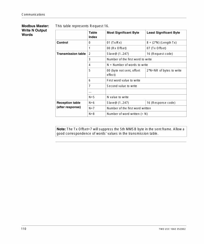
Communications
Modbus Master: Write N Output Words
This table represents Request 16.
TableIndex
Most Significant Byte Least Significant Byte
Control 0 01 (Tx/Rx) 8 + (2*N) (Length Tx)
1 00 (Rx Offset) 07 (Tx Offset)
Transmission table 2 Slave@(1..247) 16 (Request code)
3 Number of the first word to write
4 N = Number of words to write
5 00 (byte not sent, offset effect)
2*N=NR of bytes to write
6 First word value to write
7 Second value to write
...
N+5 N value to write
Reception table (after response)
N+6 Slave@(1..247) 16 (Response code)
N+7 Number of the first word written
N+8 Number of word written (= N)
Note: The Tx Offset=7 will suppress the 5th MMSB byte in the sent frame. Allow a good correspondence of words’ values in the transmission table.
110 TWD USE 10AE 05/2002

TWD USE 10AE 05/2002
6
Built-In Analog FunctionsAt a Glance
Overview This chapter describes how to manage the built-in analog channel and potentiometers.
What’s in this Chapter?
This chapter contains the following topics:
Topic Page
Potentiometers 112
Analog Channel 114
111
Built-In Analog Functions
Potentiometers
Introduction Twido controllers have:l One potentiometer on the TWDLCAA10DRF and TWDLCAA16DRF controllersl Two potentiometers on the TWDLCAA24DRF controller
Programming The numerical values, from 0 to 1023 for potentiometer 1 and 0 to 511 for potentiometer 2, corresponding to the analog values provided by these potentiometers are contained in the following two system words:l %IW0.0.0 for potentiometer 1 (leftmost)l %IW0.0.1 for potentiometer 2 (rightmost)These words can be used in arithmetic operations. They can be used for any type of adjustment, for example, presetting a time-delay or a counter, adjusting the frequency of the pulse generator or machine preheating time.
112 TWD USE 10AE 05/2002

Built-In Analog Functions
Example Adjusting the duration of a time-delay from 5 to 10 s using potentiometer 1:
The following parameters are selected at configuration for the time-delay block %TM0:l Type TONl Time base TB : 10 msThe preset value of the time-delay is calculated from the adjustment value of the potentiometer using the following equation %TM0.P := 2*%SW112+500.Code for the above example:
For this adjustment practically the entire adjustment range of the potentiometer 1 from 0 to 1023 is used.
10s
5s
0 1023
LD 1[%MW0:=2*%SW112][%TM0.P:=%MW0+500]BLK %TM0LD %I0.0INOUT_BLKLD QST %Q0.0END_BLK...................
END
IN Q
%MW0:=2*%SW112
%TM0.P:=%MW0+500
%I0.2 %Q0.0%TM0
TWD USE 10AE 05/2002 113

Built-In Analog Functions
Analog Channel
Introduction All Modular controllers (TWDLMDA20DTK, TWDLMDA20DUK, TWDLMDA20DRT, TWDLMD40DTK, and TWDLMD40DUK) have a built-in analog channel. The voltage input ranges from 0 to 10 V and the digitized signal from 0 to 511. The analog channel takes advantage of a simple averaging scheme that takes place over eight samples.
Principle An analog to digital converter samples an input voltage from 0 to 10 V to a digital value from 0 to 511. This value is stored in system word %IW0.0.1. The value is linear through the entire range, so that each count is approximately 20 mV (10 V/512). A reading of 511 is used to detect whether the maximum value of the input signal has been exceeded.
Programming Example
Controlling the temperature of an oven: The cooking temperature is set to 350°C. A variation of +/- 2.5°C results in tripping of output %Q0.1 and %Q0.2, respectively. Practically all of the possible setting ranges of the analog channel from 0 to 511 is used in this example. Analog setting for the temperature set points are:
Code for the above example:
Temperature (°C) Voltage System Word %IW0.0.1
0 0 0
347.5 7.72 395
350 7.77 398
352.5 7.83 401
450 10 511
LD [%IW0.0.1 = 395]ST %Q0.0
LD [%IW0.0.1 <= 398]ST %Q0.1
LD [%IW0.0.1 >= 401]ST %Q0.2
%IW0.0.1 = 395
%IW0.0.1 <= 398
%IW0.0.1 >= 401
%Q0.0
%Q0.1
%Q0.2
114 TWD USE 10AE 05/2002

TWD USE 10AE 05/2002
7
Managing Analog ModulesAt a Glance
Overview This chapter provides an overview of managing analog modules for Twido controllers.
What’s in this Chapter?
This chapter contains the following topics:
Topic Page
Analog Module Overview 116
Addressing Analog Inputs and Outputs 117
Configuring Analog Inputs and Outputs 119
Example of Using Analog Modules 121
115

Managing Analog Modules
Analog Module Overview
Introduction In addition to the built-in 10-bit potentiometer and 9-bit analog channel, all the Twido controllers that support expansion I/O are also able to configure and communicate analog I/O modules. These analog modules are:
Operating Analog Modules
Input and output words (%IW and %QW) are used to exchange data between the user application and any of the analog channels. The updating of these words is done synchronously with the controller scan during RUN mode.
Name Channels Signal Range Encoding
TWDAMI2HT 2 In 0 - 10 Volts or 4 - 20 mA 12 Bit
TWDAM01HT 1 Out 0 - 10 Volts or 4 - 20 mA 12 Bit
TWDAMM3HT 2 In, 1 Out 0 - 10 Volts or 4 - 20 mA 12 Bit
TWDALM3LT 2 In, 1 Out 0 - 10 Volts, Inputs Th or RTD, Outputs 4 - 20 mA
12 Bit
CAUTION
Unexpected Equipment Operation
When the controller is set to STOP, the analog output is set to its fall-back position. As is the case with digital output, the fall-back position is zero.
Failure to observe this precaution can result in injury or equipment damage.
116 TWD USE 10AE 05/2002

Managing Analog Modules
Addressing Analog Inputs and Outputs
Introduction Addresses are assigned to the analog channels depending on their location on the expansion bus.
TWD USE 10AE 05/2002 117

Managing Analog Modules
Example of Addressing Analog I/O
In this example, a TWDLMDA40DUK has its built-in 10-bit potentiometer, a 9-bit built-in analog channel. On the expansion bus, a TWDAMM3HT analog module, a TWDDMM8DRT input/output digital relay module, and a second TWDAMM3HT analog module are configured.
The table below details the addressing for each output.
Description Base Module 1 Module 2 Module 3
Potentiometer 1 %IW0.0.0
Built-in analog channelor Potentiometer 2
%IW0.0.1
Analog in channel 1 %IW0.1.0 %IW0.3.0
Analog in channel 2 %IW0.1.1 %IW0.3.1
Analog out channel 1 %QW0.1.0 %QW0.3.0
Digital in channels %I0.2.0 - %I0.2.3
Digital out channels %Q0.2.0 -%Q0.2.3
Base Module 2Module 1 Module 3
118 TWD USE 10AE 05/2002

Managing Analog Modules
Configuring Analog Inputs and Outputs
Introduction This section provides information on configuring analog module’s inputs and outputs.
Configuring Analog I/O
The Configure Module dialog box is used to manage the parameters of the analog modules.
Addresses are assigned to the analog channels depending on their location on the expansion bus. As a programming aid, you can also assign previously defined symbols to manipulate the data in your user application.You can configure channel types for the TWDAM01HT, TWDAMM3HT, and TWDALM3LT's single output channel to be:l Not used l 0 - 10 V l 4 - 20 mAYou can configure channel types for the TWDAMI2HT and TWDAMM3HT’s two input channels to be:l Not used l 0 - 10 V l 4 - 20 mA
Note: You can only modify the parameters offline, when you are not connected to a controller.
CAUTION
Unexpected Equipment Damage
If you have wired your input for a voltage measurement, and you configure TwidoSoft for a current type of configuration, you may permanently damage the analog module. Ensure that the wiring is in agreement with the TwidoSoft configuration.
Failure to observe this precaution can result in injury or equipment damage.
TWD USE 10AE 05/2002 119

Managing Analog Modules
The TWDALM3LT’s two input channels can be configured of type:l Not usedl Thermocouple Kl Thermocouple Jl Thermocouple Tl PT 100When a channel is configured, you can choose to assign units and map the range of inputs according to the following table:
Range Units Description
Normal None Fixed range from a minimum of 0 to a maximum of 4095.
Custom None User defined with a minimum of no less than -32768 and a maximum no higher than 32767
Celsius 0.1°C International thermometric scale. This is only available for the TWDALM3LT input channels.
Fahrenheit 0.1°F Thermometric scale where the boiling point of water is 212°F (100°C) and the freezing point is 32°F (0°C). This is only available for the TWDALM3LT input channels.
120 TWD USE 10AE 05/2002

Managing Analog Modules
Example of Using Analog Modules
Introduction This section provides an example of using Analog modules available with Twido.
Example This example compares the analog input signal with five separate threshold values. A comparison of the analog input is made and a bit is set on the base controller if it is less than the threshold.
%Q0.2
%IW1.0 <= 64
%Q0.1
%IW1.0 <= 32
LD [%IW1.0 <= 16]ST %Q0.0
LD [%IW1.0 <= 32]ST %Q0.1
LD [%IW1.0 <= 64]ST %Q0.2
LD [%IW1.0 <= 128]ST %Q0.3
LD [%IW1.0 <= 256]ST %Q0.4
%Q0.0
%IW1.0 <= 16
%Q0.3
%IW1.0 <= 128
%Q0.4
%IW1.0 <= 256
TWD USE 10AE 05/2002 121

Managing Analog Modules
122 TWD USE 10AE 05/2002

TWD USE 10AE 05/2002
8
Operator Display OperationAt a Glance
Overview This chapter provides details for using the optional Twido Operator Display.
What’s in this Chapter?
This chapter contains the following topics:
Topic Page
Operator Display 124
Controller Identification and State Information 127
System Objects and Variables 129
Serial Port Settings 134
Time of Day Clock 134
Real-Time Correction Factor 136
123

Operator Display Operation
Operator Display
Introduction The Operator Display is a Twido option that provides an interface for displaying and controlling application data and some controller functions such as operating state and the Real-Time Clock (RTC). This option is available as a cartridge (TWDXCPODC) for the Compact controllers or as an expansion module (TWDXCPODM) for the Modular controllers. The Operator Display has two operating modes:l Display mode: only displays data.l Edit mode: allows you to change data.
Displays and Functions
The Operator Display provides the following separate displays with the associated functions you can perform for each display.l Controller identification and state information
Display firmware revision and the controller state.Change the controller state with the Run, Initial, and Stop commands. Display error codes in the Halted state.
l System objects and variablesSelect application data by the address: %I, %Q, and all other software objects on the base controller. Monitor and change the value of a selected software data object.
l Serial port settingsDisplay and configure communication port settings.
l Time of day clockDisplay and configure the current date and time (if the RTC is installed).
l Real-Time correction factorDisplay and modify the RTC Correction value for the optional RTC.
Note: The operator display is updated at a specific interval of the controller scan cycle. This can cause confusion in interpreting the display of dedicated outputs for %PLS or %PWM pulses. At the time these outputs are sampled, their value will always be zero, and this value will be displayed. Ensure that the actual dedicated output is manipulated by the configuration of the controlling function block.
Note: Time of day clock and real-time correction are only available if the Real-Time Clock (RTC) option cartridge (TWDXCPRTC) is installed.
124 TWD USE 10AE 05/2002

Operator Display Operation
Illustration The following is a simplified diagram of the Operator Display, which consists of a display area and four push-button input keys.
Display Area The Operator Display provides an LCD display capable of displaying two lines of characters:l The first line of the display has three 13-segment characters and four 7-segment
characters.l The second line has one 13-segment character, one 3-segment character (for a
plus/minus sign), and five 7-segment characters.
Input Keys The functions of the four input push-buttons depend on the Operator Display mode:
T
V
2
4
31M
2 31
Input keys
Display area
ESCMOD/ENTER
Key In Display Mode In Edit Mode
ESC Discard changes and return to previous display.
Change current edit element to successor value.
Advance to next display. Advance to next editing element.
MOD/ENTER
Go to edit mode. Accept changes and return to previous display.
TWD USE 10AE 05/2002 125

Operator Display Operation
Selecting and Navigating the Displays
The initial display or screen of the Operator Display shows the controller identifi-
cation and state information. Press the push-button to sequence through each of the displays. The screens for the Time of Day Clock or the Real-Time Correction Factor are not displayed If the optional RTC cartridge (TWDXCPRTC) is not detected on the controller.As a shortcut, press the ESC key to return to the initial display screen. For most screens, depressing ESC will return to the Controller Identification and State Information screen. Only when editing a System Objects and Variable that is not the initial entry (%I0.0.0), will pressing ESC take you to the first or initial system object entry.
To modify an object value, instead of pressing the push-button to go to the first value digit, press the MOD/ENTER again.
126 TWD USE 10AE 05/2002

Operator Display Operation
Controller Identification and State Information
Introduction The initial display or screen of the Twido optional Operator Display shows the Controller Identification and State Information.
Example The firmware revision is displayed in the upper-right corner of the display area, and the controller state is displayed in the upper-left corner of the display area, as seen in the following:
R 2 31U N
Firmwarerevision
Controllerstate
TWD USE 10AE 05/2002 127

Operator Display Operation
Controller States Controller states include any of the following:l NCF: Not Configured
The controller is in the NCF state until an application is loaded. No other state is allowed until an application program is loaded. You can test the I/O by modifying system bit S8 (see System Bits (%S), p. 318).
l STP: StoppedOnce an application is present in the controller, the state changes to the STP or Stopped state. In this state, the application is not running. The inputs are updated and internal data is held at its last values. Outputs are not updated in this state.
l INI: InitialYou can choose to change the controller to the INI or initial state only from the STP state. The application is not running. The controller’s inputs are updated and data values are set to their initial state. No outputs are updated from this state.
l RUN: RunningWhen in the RUN or running state the application is running. The controller’s inputs are updated and data values are set according to the application. This is the only state where the outputs are updated.
l HLT: Halted (User Application Error)If the controller has entered an ERR or error state, the application is halted. Inputs are updated and data values are held at their last value. From this state, outputs are not updated. In this mode, the error code is displayed in the lower-right portion of the Operator Display as an unsigned decimal value.
l NEX: Not ExecutableAn online change was made to the user logic that caused the application to be no longer executable. The application in the PLC will not go back into the executable state until all causes for the non Exec State have been resolved.
Displaying and Changing Controller States
Using the Operator Display, you can change to the INI state from the STP state, or from STP to RUN, or from RUN to STP. Do the following to change the state of the controller:
Step Action
1 Press the key until the Operations Display is shown (or press ESC). The current controller states is displayed in the upper-left corner of the display area.
2 Press the MOD/ENTER key to enter edit mode.
3 Press the key to select a controller state.
4 Press the MOD/ENTER key to accept the modified value. Or press the ESC key to discard any modifications made while in edit mode.
128 TWD USE 10AE 05/2002

Operator Display Operation
System Objects and Variables
Introduction The optional Operator Display provides these features for monitoring and adjusting application data:l Select application data by address (such as %I or %Q).l Monitor the value of a selected software object/variable.l Change the value of the currently displayed data object (including forcing inputs
and outputs).
System Objects and Variables
The following table lists the system objects and variables, in the order accessed, that can be displayed and modified by the Operator Display.
Object Variable/Attribute Description Access
Input %I.x.y.z Value Read/Force
Output %Q.x.y.z Value Read/Write/Force
Timer %TMX.V%TMX.P%TMX.Q
Current ValuePreset ValueDone
Read/WriteRead/WriteRead
Counter %Cx.V%Cx.P%Cx.D%Cx.E%Cx.F
Current ValuePreset ValueDoneEmptyFull
Read/WriteRead/WriteReadReadRead
Memory Bit %Mx Value Read/Write
Memory Word %MWx Value Read/Write
Constant Word %KWx Value Read
System Bit %Sx Value Read/Write
System Word %SWx Value Read/Write
Analog Input %IW.x.y.z Value Read
Analog Output %QW.x.y.z Value Read/Write
Fast Counter %FCx.V%FCx.P%FCx.D
Current ValuePreset valueDone
Read/WriteRead/WriteRead
TWD USE 10AE 05/2002 129

Operator Display Operation
Notes:1. Variables will not be displayed if they are not used in an application since Twido
uses dynamic memory allocation.2. If the value of %MW is greater than +32767 or less than -32787, the operator
display will continue to blink.3. If the value of %SW is greater than 65535, the operator display continues to blink,
except for %SW0 and %SW11. If a value is entered that is more than the limit, the value will return to the configured value.
4. If a value is entered for %PLS.P that is more than the limit, the value will be set to saturation.
Very Fast Counter %VFCx.V%VFCx.P%VFCx.U%VFCx.C%VFCx.S0%VFCx.S1%VFCx.F%VFCx.M%VFC.T%VFC.R%VFC.S
Current ValuePreset ValueCount DirectionCatch ValueThreshold Value 0Threshold Value1OverflowFrequency DoneTimebaseReflex Output EnableReflex Input Enable
Read/WriteRead/WriteReadReadRead/WriteRead/WriteReadRead/WriteRead/WriteRead/WriteRead/Write
Input Network Word %INWx.z Value Read/Write
Output Network Word %QNWx.z Value Read/Write
Grafcet %Xx Step Bit Read
Pulse Generator %PLS.N%PLS.P%PLS.D%PLS.Q
Number of PulsesPreset valueDoneCurrent Output
Read/WriteRead/WriteReadRead
Pulse Width Modulator
%PMW.R%PMW.P
RatioPreset value
Read/WriteRead/Write
Drum Controller %DRx.S%DRx.F
Current Step Number Full
ReadRead
Step Counter %SCx.n Step Counter bit Read/Write
Register %Rx.I%Rx.O%Rx.E%Rx.F
Input Output EmptyFull
Read/WriteReadReadRead
Shift Bit Register %SBR.x.yy Register Bit Read/Write
Message %MSGx.D%MSGx.E
DoneError
ReadRead
Object Variable/Attribute Description Access
130 TWD USE 10AE 05/2002

Operator Display Operation
Displaying and Modifying Objects and Variables
Each type of system object is accessed by starting with the Input Object (%I), sequencing through to the Message object (%MSG), and finally looping back to the Input Object (%I). To display a system object:
Data Values and Display Formats
In general, the data value for an object or variable is shown as a signed or unsigned integer in the lower-right of the display area. In addition, all fields suppress leading zeros for displayed values. The address of each object is displayed on the Operator Display in one of the following six formats:l I/O formatl Function block formatl Simple formatl Network I/O formatl Step counter format l Shift bit register format
Step Action
1 Press the key until the Data Display screen is shown.The Input object ("I") will be displayed in the upper left corner of the display area. The "I" character (or previous object name) is not blinking.
2 Press the MOD/ENTER key to enter edit mode.The Input Object "I" character (or previous object name) begins blinking.
3 Press the key to step sequentially through the list of objects.
4 Press the key to step sequentially through the field of an object type and press
the key to increment through the value of that field. You can use the key
and key to navigate and modify all fields of the displayed object.
5 Repeat Steps 3 and 4 until editing is complete.
6 Press the MOD/ENTER key to accept the modified values.Note: The object’s name and address have to be validated before accepting any modifications. That is, they must exist in the configuration of the controller prior to using the operator display.Press ESC to discard any changes made in edit mode.
TWD USE 10AE 05/2002 131

Operator Display Operation
Input/Output Format
The input/output objects (%I, %Q, %IW, and %QW) have three-part addresses such as %IX.Y.Z and are displayed as follows:l Object type and controller address in the upper-leftl Expansion address in the upper-centerl I/O channel in the upper-rightIn the case of a simple input (%I) and output (%Q), the lower-left portion of the display will contain a character that is either "U" for unforced or "F" for a forced bit. The force value is displayed in the lower-right of the screen.The output object %Q0.3.11 appears in the display area as follows:
Function Block Format
The function blocks (%TM, %C, %FC, %VFC, %PLS, %PWM, %DR, %R, and %MSGj) have two-part addresses containing an object number and a variable or attribute name and are displayed as follows:l Function block name in the upper-leftl Function block number (or instance) in the upper-rightl The variable or attribute in the lower-leftl Value for the attribute in the lower-rightIn the following example, the current value for timer number 123 is set to 1,234.
Simple Format A simple format is used for objects %M, %MW, %KW, %S, %SW, and %X as follows:l Object number in the upper-rightl Signed value for the objects in the lower portionIn the following example, memory word number 67 contains the value +123.
Q
F
0 3 1
1
1
T
V
2
4
31M
2 31
M 6
3
7W
1 2+
132 TWD USE 10AE 05/2002

Operator Display Operation
Network Input/Output Format
The network input/output objects (%INW and %QNW) appear in the display area as follows:l The object name in the upper-leftl Controller address in the upper-centerl Object number in the upper-rightl Signed value for the object in the lower portionIn the following example, the first input or network word of the remote controller configured at remote address #2 is set to the value -4.
Step Counter Format
The step counter (%SC) format displays the object number and the step counter bit as follows:l Object name and number in the upper leftl The step counter bit in the upper rightl The value of the object in the lower portion of the displayIn the following example, bit number 129 of step counter number 3 is set to -1.
Shift Bit Register Format
The shift bit register (%SBR) format displays an object number and the register bit as follows:l Object name and number in the upper leftl The register bit in the upper rightThe following example shows the display of shift bit register number 4.
M
4
1
-N W 2
S
1
9
-C 3 1 2
S
1
9B R 4
TWD USE 10AE 05/2002 133

Operator Display Operation
Serial Port Settings
Introduction You can display and modify protocol settings using the Operator Display. The maximum number of serial ports is two. In the example below, the first port is configured as Modbus protocol with an address 123. The second serial port is configured as a Remote Link with an address of 5.
Displaying and Modifying Serial Port Settings
Twido controllers can support up to two serial ports. To display the serial port settings using the operator display:
Time of Day Clock
Introduction You can modify the date and time using the operator display if the RTC option cartridge (TWDXCPRTC) is installed on your Twido controller. The Month is displayed in the upper-left side of the HMI Display. Until a valid time has been entered, the month field will contain the value "RTC". The day of the month is displayed in the upper-right corner of the display. The time of day is in military format. The hours and minutes are shown in the lower-right corner of the display and are separated by the letter "h". The example below shows that the RTC is set to March 28, at 2:22 PM.
M
R
2
4
31
Step Action
1 Press the key until the Communication Display is shown. The single letter of the protocol setting of the first serial port ("M", "R", or "A") will be displayed in the upper left corner of the operator display.
2 Press the MOD/ENTER key to enter the edit mode.
3 Press the key until you are in the field that you wish to modify.
4 Press the key increment the value of that field.
5 Continue steps 3 and 4 until the Serial Port Settings are complete.
6 Press the MOD/ENTER key to accept the modified values or ESC to discard any modifications made while in edit mode.
M 8A R 2
24 h1 2
134 TWD USE 10AE 05/2002

Operator Display Operation
Displaying and Modifying Time of Day Clock
To display and modify the Time of Day Clock:
Step Action
1 Press the key until the Time/Date Display is shown. The month value ("JAN", "FEB") will be displayed in the upper-left corner of the display area. The value "RTC" will be displayed in the upper-left corner if no month has been initialized.
2 Press the MOD/ENTER key to enter the edit mode.
3 Press the key until you are in the field that you wish to modify.
4 Press the key increment the value of that field.
5 Continue steps 3 and 4 until the Time of Day value is complete.
6 Press the MOD/ENTER key to accept the modified values or ESC to discard any modifications made while in edit mode.
TWD USE 10AE 05/2002 135

Operator Display Operation
Real-Time Correction Factor
Introduction You can display and modify the Real-Time Correction Factor using the operator display. Each Real-Time Clock (RTC) Option module has a RTC Correction Factor value that is used to correct for inaccuracies in the RTC module’s crystal. The correction factor is an unsigned 3-digit integer from 0 to 127 and is displayed in the lower-right corner of the display. The example below shows a correction factor of 127.
Displaying and Modifying RTC Correction
To display and modify the Real-Time Correction Factor:
R T C
21 7
C o r r
Step Action
1 Press the key until the RTC Factor Display is shown. "RTC Corr" will be displayed in the upper line of the operator display.
2 Press the MOD/ENTER key to enter the edit mode.
3 Press the key until you are in the field that you wish to modify.
4 Press the key increment the value of that field.
5 Continue Steps 3 and 4 until the RTC correction value is complete.
6 Press the MOD/ENTER key to accept the modified values or ESC to discard any modifications made while in edit mode.
136 TWD USE 10AE 05/2002

TWD USE 10AE 05/2002
III
Description of Twido LanguagesAt a Glance
Overview This part provides instructions for using the Ladder, List, and Grafcet programming languages to create control programs for Twido programmable controllers.
What’s in this Part?
This part contains the following topics:
Chapter Chaptername Page
9 Ladder Language 139
10 Instruction List Language 161
11 Grafcet 175
137

Description of Twido Languages
138 TWD USE 10AE 05/2002

TWD USE 10AE 05/2002
9
Ladder LanguageAt a Glance
Overview This chapter describes programming with Ladder language.
What’s in this Chapter?
This chapter contains the following topics:
Topic Page
Introduction to Ladder Diagrams 140
Programming Principles for Ladder Diagrams 142
Ladder Diagram Blocks 144
Ladder Language Graphic Elements 147
Special Ladder Instructions OPEN and SHORT 150
Programming Advice 151
Ladder/List Reversibility 156
Guidelines for Ladder/List Reversibility 157
Program Documentation 159
139

Ladder Language
Introduction to Ladder Diagrams
Introduction Ladder diagrams are similar to relay logic diagrams that represent relay control circuits. The main differences between the two are the following features of Ladder programming that are not found in relay logic diagrams: l All inputs are represented by contact symbols ( ).l All outputs are represented by coil symbols ( ).l Numerical operations are included in the graphical Ladder instruction set.
Ladder Equivalents to Relay Circuits
The following illustration shows a simplified wiring diagram of a relay logic circuit and the equivalent Ladder diagram.
Notice that in the above illustration, all inputs associated with a switching device in the relay logic diagram are shown as contacts in the Ladder diagram. The M1 output coil in the relay logic diagram is represented with an output coil symbol in the Ladder diagram. The address numbers appearing above each contact/coil symbol in the Ladder diagram are references to the locations of the external input/output connections to the controller.
Relay logic circuit Ladder diagram
LS1 PB1 CR1 M1
LS2 SS1
%I0.2 %I0.4%I0.0
%I0.1 %I0.7
%Q0.4LS1 PB1 CR1 M1
LS2 SS1
140 TWD USE 10AE 05/2002

Ladder Language
Ladder Rungs A program written in Ladder language is composed of rungs which are sets of graphical instructions drawn between two vertical potential bars. The rungs are executed sequentially by the controller.The set of graphical instructions represent the following functions:l Inputs/outputs of the controller (push buttons, sensors, relays, pilot lights, ...)l Functions of the controller (timers, counters, ...)l Math and logic operations (addition, division, AND, XOR, ...)l Comparison operators and other numerical operations (A<B, A=B, shift, rotate,
...)l Internal variables in the controller (bits, words, ...)These graphical instructions are arranged with vertical and horizontal connections leading eventually to one or several outputs and/or actions. A rung cannot support more than one group of linked instructions.
Example of Ladder Rungs
The following diagram is an example of a Ladder program composed of two rungs.
Example Rung 1
Example Rung 2
%I0.1
%I0.3
%M42 %Q1.2
%M42
%M22:=%MW15+%KW1
TWD USE 10AE 05/2002 141

Ladder Language
Programming Principles for Ladder Diagrams
Programming Grid
Each Ladder rung consists of a grid of seven rows by eleven columns that are organized into two zones as shown in the following illustration.
Grid Zones The Ladder diagram programming grid is divided into two zones:l Test Zone
Contains the conditions that are tested in order to perform actions. Consists of columns 1 - 10, and contains contacts, function blocks, and comparison blocks.
l Action ZoneContains the output or operation that will be performed according to the results of the tests of the conditions in the Test Zone. Consists of columns 8 - 11, and contains coils and operation blocks.
Test Zone
Action Zone
2
3
4
6
7
2 43 5 6 7 109 11
5
1
1 8
Rows
Columns
GridCells
Potential Bars
142 TWD USE 10AE 05/2002

Ladder Language
Entering Instructions in the Grid
A Ladder rung provides a seven by eleven programming grid that starts in the first cell in the upper left-hand corner of the grid. Programming consists of entering instructions into the cells of the grid. Test instructions, comparisons, and functions are entered in cells in the test zone and are left-justified. The test logic provides continuity to the action zone where coils, numerical operations, and program flow control instructions are entered and are right-justified.The rung is solved or executed (tests made and outputs assigned) within the grid from top to bottom and from left to right.
Rung Headers In addition to the rung, a rung header appears directly above the rung. Use the rung header to document the logical purpose of the rung. The rung header can contain the following information:l Rung numberl Labels (%Li)l Subroutine declarations (SRi:)l Rung titlel Rung commentsFor more details about using the rung header to document your programs, see Program Documentation, p. 159.
TWD USE 10AE 05/2002 143

Ladder Language
Ladder Diagram Blocks
Introduction Ladder diagrams consist of blocks representing program flow and functions such as the following: l Contactsl Coilsl Program flow instructionsl Function blocksl Comparison blocksl Operate blocks
Contacts, Coils, and Program Flow
Contacts, coils, and program flow (jump and call) instructions occupy a single cell of the ladder programming grid. Function blocks, comparison blocks, and operate blocks occupy multiple cells.The following are examples of a contact and a coil.
Contact Coil
144 TWD USE 10AE 05/2002

Ladder Language
Function Blocks Function blocks are placed in the test zone of the programming grid. The block must appear in the first row; no ladder instructions or lines of continuity may appear above or below the function block. Ladder test instructions lead to the function block’s input side, and test instructions and/or action instructions lead from the block’s output side.Function blocks are vertically oriented and occupy two columns by four rows of the programming grid.The following is an example of a counter function block.
R
S
CU
CD
E
D
F
%C0
ADJ Y%C0.P 9999
TWD USE 10AE 05/2002 145

Ladder Language
Comparison Blocks
Comparison blocks are placed in the test zone of the programming grid. The block may appear in any row or column in the test zone as long as the entire length of the instruction resides in the test zone.Comparison blocks are horizontally oriented and occupy two columns by one row of the programming grid.See the following example of a comparison block.
Operate Blocks Operate blocks are placed in the action zone of the programming grid. The block may appear in any row in the action zone. The instruction is right-justified; it appears on the right and ends in the last column.Operate blocks are horizontally oriented and occupy four columns by one row of the programming grid. The following is an example of an operate block.
%MW0=%SW50
%MW120 := SQRT (%MW15)
146 TWD USE 10AE 05/2002

Ladder Language
Ladder Language Graphic Elements
Introduction Instructions in Ladder diagrams consist of graphic elements. This section lists and describes graphic elements used in Twido Ladder instructions. See the TwidoSoft Operation Guide for details on using these graphic elements in Twido Ladder programs.
Contacts The contacts graphic elements are programmed in the test zone and take up one cell (one row high by one column wide).
Link Elements The graphic link elements are used to connect the test and action graphic elements.
Name Graphic element
Instruction Function
Normally open contact LD Passing contact when the controlling bit object is at state 1.
Normally closed contact
LDN Passing contact when the controlling bit object is at state 0.
Contact for detecting a rising edge
LDR Rising edge: detecting the change from 0 to 1 of the controlling bit object.
Contact for detecting a falling edge
LDF Falling edge: detecting the change from 1 to 0 of the controlling bit object.
P
N
Name Graphic element
Functions
Horizontal connector Links in series the test and action graphic elements between the two potential bars.
Down connector Links the test and action graphic elements in parallel (a vertical connection).
TWD USE 10AE 05/2002 147

Ladder Language
Coils The coil graphic elements are programmed in the action zone and take up one cell (one row high and one column wide).
Name Graphic element
Instruction Functions
Direct coil ST The associated bit object takes the value of the test zone result.
Negated coil STN The associated bit object takes the negated value of the test zone result.
Set coil S The associated bit object is set to 1 when the result of the test zone is 1.
Reset coil R The associated bit object is set to 0 when the result of the test zone is 1.
Jump or Subroutine call
JMPSR
Connect to a labeled instruction, upstream or downstream.
Transition condition coil
Provided in Grafcet language, used when the programming of the transition conditions associated with the transitions causes a changeover to the next step.
Return from a subroutine
RET Placed at the end of subroutines to return to the main program.
Stop program END Defines the end of the program.
S
R
->>%Li->>%SRi
#
<RET>
<END>
148 TWD USE 10AE 05/2002

Ladder Language
Function Blocks The graphic elements of function blocks are programmed in the test zone and require four rows by two columns of cells (except for very fast counters which require five rows by two columns).
Operate and Comparison Blocks
Comparison blocks are programmed in the test zone, and operate blocks are programmed in the action zone.
Name Graphic element
Functions
Timers, counters, registers, and so on.
Each of the function blocks uses inputs and outputs that enable links to the other graphic elements..Note: Outputs of function blocks can not be connected o each other (vertical shorts).
Name Graphic element
Functions
Comparison block Compares two operands, the output changes to 1 when the result is checked.Size: one row by two columns
Operation block Performs arithmetic and logic operations.Size: one row by four columns
TWD USE 10AE 05/2002 149

Ladder Language
Special Ladder Instructions OPEN and SHORT
Introduction The OPEN and SHORT instructions provide a convenient method for debugging and troubleshooting Ladder programs. These special instructions alter the logic of a rung by either shorting or opening the continuity of a rung as explained in the following table.
In List programming, the OR and AND instructions are used to create the OPEN and SHORT instructions using immediate values of 0 and 1 respectively.
Examples The following are examples of using the OPEN and SHORT instructions.
Instruction Description List Instruction
OPEN Creates a break in the continuity of a ladder rung regardless of the results of the last logical operation.
AND 0
SHORT Allows the continuity to pass through the rung regardless of the results of the last logical operation.
OR 1
LD %I0.1OR %Q1.5ANDN %M3AND 0ST %Q0.1LD %I0.9OR 1ST %Q1.6
%Q1.6%I0.9
%Q0.1%M3%I0.1
%Q1.5
OPEN
SHORT
150 TWD USE 10AE 05/2002

Ladder Language
Programming Advice
Handling Program Jumps
Use program jumps with caution to avoid long loops that can increase scan time. Avoid jumps to instructions that are located upstream. (An upstream instruction line appears before a jump in a program, while a downstream instruction line appears after a jump in a program.)
Programming of Outputs
An output bit or internal bit can only be controlled once in the program. In the case of output bits, only the last value scanned is taken into account when the outputs are updated.
Using Directly-Wired Emergency Stop Sensors
Sensors used directly for emergency stops must not be processed by the controller. They must be connected directly to the corresponding outputs.
Handling Power Returns
Make power returns conditional on a manual operation, as an automatic restart of the installation could cause unexpected operation of equipment (use system bits %S0, %S1 and %S9).
Time and Schedule Block Management
The state of system bit %S51, which indicates any schedule block faults, should be checked.
Syntax and Error Checking
When a program is entered, TwidoSoft checks the syntax of the instructions, the operands, and their association. See the TwidoSoft Operation Guide for more details.
TWD USE 10AE 05/2002 151

Ladder Language
Additional Notes on Using Parentheses
Assignment operations should not be placed within parentheses:
In order to perform the same function, the following equations must be programmed:
LD %I0.0AND %I0.1OR( %I0.2ST %Q0.0AND %I0.3)ST %Q0.1
%I0.0 %I0.1
%I0.2 %I0.3
%Q0.1
%Q0.0
LD %I0.0MPSAND( %I0.1OR( %I0.2AND %I0.3))ST %Q0.1MPPAND %I0.2ST %Q0.0
%I0.0 %I0.1
%I0.2
%I0.2
%I0.3
%Q0.1
%Q0.0
152 TWD USE 10AE 05/2002

Ladder Language
If several contacts are placed in parallel, they should either be nested within one another or totally dissociated from each other:
%I0.0 %I0.1 %I0.5 %Q0.1
%I0.2 %I0.3
%I0.6 %I0.7
%I0.0 %I0.1 %I0.5 %Q0.1
%I0.2 %I0.4
TWD USE 10AE 05/2002 153

Ladder Language
The following schematics cannot be programmed:
%I0.0 %I0.1 %Q0.1
%I0.2 %I0.3
%I0.4
%I0.0 %I0.1 %I0.5 %Q0.1
%I0.2 %I0.3
%I0.4
154 TWD USE 10AE 05/2002

Ladder Language
In order to execute schematics equivalent to those, they must be modified as follows:
LD %I0.0AND( %I0.1OR( %I0.2AND %I0.3))OR( %I0.4AND %I0.3)ST %Q0.1
LD %I0.0AND( %I0.1OR( %I0.2AND %I0.3)AND %I0.5OR( %I0.2AND %I0.4))ST %Q0.1
%I0.0 %I0.1
%I0.2 %I0.3
%I0.4 %I0.3
%I0.0 %I0.1 %I0.5 %Q0.1
%I0.2 %I0.3
%I0.2 %I0.4
%Q0.1
TWD USE 10AE 05/2002 155

Ladder Language
Ladder/List Reversibility
Introduction Program reversibility is a feature of the TwidoSoft programming software that provides conversion of application programs from Ladder to List and from List back to Ladder.Use TwidoSoft to set the default display of programs for either List or Ladder format (by setting user preferences), and to toggle List and Ladder views (see the TwidoSoft Operation Guide for more details).
Understanding Reversibility
A key to understanding the program reversibility feature is examining the relationship of a Ladder rung and the associated instruction List sequence:l Ladder rung: A collection of Ladder instructions that constitute a logical
expression.l List sequence: A collection of List programming instructions that correspond to
the Ladder instructions and represents the same logical expression. The following illustration displays a common Ladder rung and its equivalent program logic expressed as a sequence of List instructions.
An application program is stored internally as List instructions, regardless if the program is written in Ladder language or List language. TwidoSoft takes advantage of the program structure similarities between the two languages and uses this internal List image of the program to display it in the List and Ladder viewers and editors as either a List program (its basic form), or graphically as a Ladder diagram, depending upon the selected user preference.
Ensuring Reversibility
Programs created in Ladder can always be reversed to List, but some List logic may not reverse to Ladder. To ensure reversibility from List to Ladder, it is important to follow the set of List programming guidelines in Guidelines for Ladder/List Reversibility, p. 157 .
LD %I0.5OR %I0.4ST %Q0.4
%I0.5 %Q0.4
%I0.4
156 TWD USE 10AE 05/2002

Ladder Language
Guidelines for Ladder/List Reversibility
Instructions Required for Reversibility
The structure of a reversible function block in List language requires the use of the following instructions:l BLK marks the block start, and defines the beginning of the rung and the start of
the input portion to the block.l OUT_BLK marks the beginning of the output portion of the block.l END_BLK marks the end of the block and the rung.The use of the reversible function block instructions are not mandatory for a properly functioning List program. For some instructions it is possible to program in List which is not reversible. For a description of non-reversible List programming of standard function blocks, see Principles for Programming Basic Function Blocks, p. 208.
Non-Equivalent Instructions to Avoid
Avoid the use of certain List instructions, or certain combinations of instructions and operands, which have no equivalents in Ladder diagrams. For example, the N instruction (inverses the value in the Boolean accumulator) has no equivalent Ladder instruction.The following table identifies all List programming instructions that will not reverse to Ladder.
List Instruction Operand Description
JMPCN %Li Jump Conditional Not
N none Negation (Not)
ENDCN none End Conditional Not
TWD USE 10AE 05/2002 157

Ladder Language
Unconditional Rungs
Programming unconditional rungs also requires following List programming guidelines to ensure List-to-Ladder reversibility. Unconditional rungs do not have tests or conditions, the outputs or action instructions are always energized or executed.The following diagram provides examples of unconditional rungs and the equivalent List sequence.
Notice that each of the above unconditional List sequences begin with a load instruction followed by a one, except for the JMP instruction. This combination sets the Boolean accumulator value to one, and therefore sets the coil (store instruction) to one and sets%MW5 to zero on every scan of the program. The exception is the unconditional jump List instruction (JMP %L6) which is executed regardless of the value of the accumulator and does not need the accumulator set to one.
Ladder List Rungs
If a List program is reversed that is not completely reversible, the reversible portions are displayed in the Ladder view and the irreversible portions are displayed in Ladder List Rungs.A Ladder List Rung functions just like a small List editor, allowing the user to view and modify the irreversible parts of a Ladder program.
LD 1ST %Q0.4LD 1[%MW5 := 0]JMP %L6
%Q0.4
%MW5 := 0
>>%L6
158 TWD USE 10AE 05/2002

Ladder Language
Program Documentation
Documenting Your Program
You can document your program by entering comments using the List and Ladder editors (see the TwidoSoft Operation Guide for details on using these program editors):l Use the List Editor to document your program with List Line Comments. These
comments may appear on the same line as programming instructions, or they may appear on lines of their own.
l Use the Ladder Editor to document your program using rung headers found directly above the rung.
The TwidoSoft programming software uses these comments for reversibility, When reversing a program from List to Ladder, TwidoSoft uses some of the List comments to construct a rung header, and the comments inserted between List sequences are used for rung headers.
Example of List Line Comments
The following is an example of a List program with List Line Comments.
---- ( * THIS IS THE TITLE OF THE HEADER FOR RUNG 0 * )---- ( * THIS IS THE FIRST HEADER COMMENT FOR RUNG 0 * )---- ( * THIS IS THE SECOND HEADER COMMENT FOR RUNG 0 * )
0 LD % I0. 0 ( * THIS IS A LINE COMMENT *)1 OR %I0. 1 ( * A LINE COMMENT IS IGNORED WHEN REVERSING TO LADDER * )2 ANDM %M103 ST M101
---- ( * THIS IS THE HEADER FOR RUNG 1 * )---- ( * THIS RUNG CONTAINS A LABEL * )---- ( * THIS IS THE SECOND HEADER COMMENT FOR RUNG 1 * )---- ( * THIS IS THE THIRD HEADER COMMENT FOR RUNG 1 * )---- ( * THIS IS THE FOURTH HEADER COMMENT FOR RUNG 1 * )
4 % L5:5 LD %M1016 [ %MW20 := %KW2 * 16 ]
---- ( * THIS RUNG ONLY CONTAINS A HEADER TITLE * )7 LD %Q0. 58 OR %I0. 39 ORR I0. 13
10 ST %Q0.5
TWD USE 10AE 05/2002 159

Ladder Language
Reversing List Comments to Ladder
When List instructions are reversed to a Ladder diagram, List Line Comments are displayed in the Ladder Editor according to the following rules:l The first comment that is on a line by itself is assigned as the rung header.l Any comments found after the first become the body of the rung.l Once the body lines of the header are occupied, then the rest of the line
comments between List sequences are ignored, as are any comments that are found on list lines that also contain list instructions.
Example of Rung Header Comments
The following is an example of a Ladder program with rung header comments.
Reversing Ladder Comments to List
When a Ladder diagram is reversed to List instructions, rung header comments are displayed in the List Editor according to the following rules:l Any rung header comments are inserted between the associated List sequences.l Any labels (%Li:) or subroutine declarations (SRi:) are placed on the next line
following the header and immediately prior to the beginning of the List sequence.l If the List was reversed to Ladder, any comments that were ignored will reappear
in the List Editor.
160 TWD USE 10AE 05/2002

TWD USE 10AE 05/2002
10
Instruction List LanguageAt a Glance
Overview This chapter describes programming in the Instruction List language.
What’s in this Chapter?
This chapter contains the following topics:
Topic Page
Overview of List Programs 162
Operation of List Instructions 164
List Language Instructions 165
Using Parentheses 169
Stack Instructions (MPS, MRD, MPP) 172
161

Instruction List Language
Overview of List Programs
Introduction A program written in List language consists of a series of instructions executed sequentially by the controller. Each List instruction is represented by a single program line and consists of three components:l Line numberl Instruction codel Operand(s)
Example of a List Program
The following is an example of a List program.
Line Number Line numbers are generated automatically when you enter an instruction. Blank lines and Comment lines do not have line numbers.
Instruction Code The instruction code is a symbol for an operator that identifies the operation to be performed using the operand(s). Typical operators specify Boolean and numerical operations.For example, in the sample program above, LD is the abbreviation for the instruction code for a LOAD instruction. The LOAD instruction places (loads) the value of the operand %I0.1 into an internal register called the accumulator.There are basically two types of instructions:l Test instructions
These setup or test for the necessary conditions to perform an action. For example, LOAD (LD) and AND.
l Action instructionsThese perform actions as a result of setup conditions. For example, assignment instructions such as STORE (ST) and RESET (R).
1 ST %Q0.32 LDN %M03 ST %Q0.24 LDR %I0.25 ST %Q0.46 LDF %I0.37 ST %Q0.5
%I0.1LD
Operand(s)
Line Number
Instruction Code
0
0 LD %I0.1
162 TWD USE 10AE 05/2002

Instruction List Language
Operand An operand is a number, address, or symbol representing a value that a program can manipulate in an instruction. For example, in the sample program above, the operand %I0.1 is an address assigned the value of an input to the controller. An instruction can have from zero to three operands depending on the type of instruction code.Operands can represent the following:l Controller inputs and outputs such as sensors, push buttons, and relays.l Predefined system functions such as timers and counters. l Arithmetic, logical, comparison, and numerical operations.l Controller internal variables such as bits and words.
TWD USE 10AE 05/2002 163

Instruction List Language
Operation of List Instructions
Introduction List instructions have only one explicit operand, the other operand is implied. The implied operand is the value in the Boolean accumulator. For example, in the instruction LD %I0.1, %I0.1 is the explicit operand. An implicit operand is stored in the accumulator and will be written over by value of %I0.1.
Operation A List instruction performs a specified operation on the contents of the accumulator and the explicit operand, and replaces the contents of the accumulator with the result. For example, the operation AND %I1.2 performs a logical AND between the contents of the accumulator and the Input 1.2 and will replace the contents of the accumulator with this result.All Boolean instructions, except for Load, Store, and Not, operate on two operands. The value of the two operands can be either True or False, and program execution of the instructions produce a single value, either True or False. Load instructions place the value of the operand in the accumulator, while Store instructions transfer the value in the accumulator to the operand. The Not instruction has no explicit operands and simply inverts the state of the accumulator.
Supported List Instructions
The following table is a summary of the types of supported List instructions.
Type of Instruction Example Function
Bit instruction LD %M10 Reads internal bit %M10
Block instruction IN %TM0 Starts the timer %TM0
Word instruction [%MW10 := %MW50+100] Addition operation
Program instruction SR5 Calls subroutine #5
Grafcet instruction -*-8 Step #8
164 TWD USE 10AE 05/2002

Instruction List Language
List Language Instructions
Introduction List language consists of the following types of instructions:l Test instructionsl Action instructionsl Function block instructionsThis section identifies and describes the Twido instructions for List programming.
Test Instructions The following table describes test instructions in List language.
Name Equivalent graphic element
Function
LD The Boolean result is the same as the status of the operand.
LDN The Boolean result is the same as the reverse status of the operand.
LDR The Boolean result changes to 1 on detection of the operand (rising edge) changing from 0 to 1.
LDF The Boolean result changes to 1 on detection of the operand (falling edge) changing from 1 to 0.
AND The Boolean result is equal to the AND logic between the Boolean result of the previous instruction and the status of the operand.
ANDN The Boolean result is equal to the AND logic between the Boolean result of the previous instruction and the reverse status of the operand.
ANDR The Boolean result is equal to the AND logic between the Boolean result of the previous instruction and the detection of the operand’s rising edge (1 = rising edge).
ANDF The Boolean result is equal to the AND logic between the Boolean result of the previous instruction and the detection of the operand’s falling edge (1 = falling edge).
OR The Boolean result is equal to the OR logic between the Boolean result of the previous instruction and the status of the operand.
P
N
P
N
TWD USE 10AE 05/2002 165

Instruction List Language
AND( Logic AND (8 parenthesis levels)
OR( Logic OR (8 parenthesis levels)
XOR, XORN, XORR, XORF
Exclusive OR
MPSMRDMPP
Switching to the coils.
N - Negation (NOT)
Name Equivalent graphic element
Function
XORF
XORF
XORN
XOR
166 TWD USE 10AE 05/2002

Instruction List Language
Action instructions
The following table describes action instructions in List language.
Name Equivalent graphic element
Functions
ST The associated operand takes the value of the test zone result.
STN The associated operand takes the reverse value of the test zone result.
S The associated operand is set to 1 when the result of the test zone is 1.
R The associated operand is set to 0 when the result of the test zone is 1.
JMP Connect unconditionally to a labeled sequence, upstream or downstream.
SRn Connection at the beginning of a subroutine.
RET Return from a subroutine.
END End of program.
ENDC End of the conditioned program at a Boolean result of 1.
ENDCN End of the conditioned program at a Boolean result of 0.
S
R
->>%Li
->>%SRi
<RET>
<END>
<ENDC>
<ENDCN>
TWD USE 10AE 05/2002 167

Instruction List Language
Function Block Instructions
The following table describes function blocks in List language.
Name Equivalent graphic element
Functions
Timers, counters, registers, and so on.
For each of the function blocks, there are instructions for controlling the block. A structured form is used to hardwire the block inputs and outputs directly.Note: Outputs of function blocks can not be connected to each other (vertical shorts).
168 TWD USE 10AE 05/2002

Instruction List Language
Using Parentheses
Introduction Use parentheses in AND and OR logic instructions to indicate parallel branches in Ladder diagrams. The open and closed parentheses are associated with instructions as follows: l Opening the parentheses is associated with the AND or OR instruction.l Closing the parentheses is an instruction which is required for each open
parentheses.
Example Using an AND Instruction
The following diagrams are examples of using a parentheses with an AND instruction: AND(...).
Example Using an OR Instruction
The following diagrams are examples of using a parentheses with an OR instruction: OR(...).
LD %I0.0AND %I0.1OR %I0.2ST %Q0.0
LD %I0.0AND( %I0.1OR %I0.2)ST %Q0.1
%Q0.1
%Q0.0
%I0.2
%I0.0
%I0.1
%I0.2
%I0.0
%I0.1
LD %I0.0AND %I0.1OR( %I0.2AND %I0.3)ST %Q0.0
%Q0.0%I0.0 %I0.1
%I0.2 %I0.3
TWD USE 10AE 05/2002 169

Instruction List Language
Modifiers The following table lists modifiers that can be assigned to parentheses.
Nesting Parenthesis
It is possible to nest up to eight levels of parentheses. Observe the following rules when nesting parentheses:l Each open parentheses must have a corresponding closed parentheses.l Labels (%Li:), subroutines (SRi:), jump instructions (JMP), and function block
instructions must not be placed in expressions between parentheses.l Store instructions ST, STN, S, and R must not be programmed between
parentheses.l Stack instructions MPS, MRD, and MPP cannot be used between parentheses.
Modifier Function Example
N Negation AND(N or OR(N
F Falling edge AND(F or OR(F
R Rising edge AND(R or OR(R
[ Comparison See Comparison Instructions, p. 236
170 TWD USE 10AE 05/2002

Instruction List Language
Examples of Nesting Parentheses
The following diagrams provide examples of nesting parentheses.
LD %I0.0AND( %I0.1OR(N %I0.2AND %M3))ST %Q0.0
LD %I0.1AND( %I0.2AND %I0.3OR( %I0.5AND %I0.6)AND %I0.4OR( %I0.7AND %I0.8))ST %Q0.0
%Q0.0
%Q0.0%I0.1
%I0.0 %I0.1
%I0.2 %M3
%I0.2 %I0.3 %I0.4
%I0.6%I0.5
%I0.7 %I0.8
TWD USE 10AE 05/2002 171

Instruction List Language
Stack Instructions (MPS, MRD, MPP)
Introduction The Stack instructions process routing to coils.The MPS, MRD, and MPP instructions use a temporary storage area called the stack which can store up to eight Boolean expressions.
Operation of Stack Instructions
The following table describes the operation of the three stack instructions.
Note: These instructions can not be used within an expression between parentheses.
Instruction Description Function
MPS Memory Push onto stack Stores the result of the last logical instruction (contents of the accumulator) onto the top of stack (a push) and shifts the other values to the bottom of the stack.
MRD Memory Read from stack Reads the top of stack into the accumulator.
MPP Memory Pop from stack Copies the value at the top of stack into the accumulator (a pop) and shifts the other values towards the top of the stack.
172 TWD USE 10AE 05/2002

Instruction List Language
Examples of Stack Instructions
The following diagrams are examples of using stack instructions.
Examples of Stack Operation
The following diagrams display how stack instructions operate.
LD %I0.0AND %M1MPSAND %I0.1ST %Q0.0MRDAND %I0.2ST %Q0.1MRDAND %I0.3ST %Q0.2MPPAND %I0.4ST %Q0.3
%Q0.0
%Q0.1
%Q0.3
%Q0.2
%M1
%I0.2
%I0.3
%I0.4
%I0.1%I0.0
MPS
MPP
MRD
LD %I0.0MPSAND %I0.1MPSAND( %I0.3OR %M0)ST %Q0.0MPPANDN %M1ST %Q0.1MRDAND %I0.4ST %Q0.2MPPAND %M10ST %Q0.3
%Q0.0
%I0.4
%Q0.1
%Q0.2
%Q0.3
%I0.0 %I0.1 %I0.3
%M0
%M1
%M10
TWD USE 10AE 05/2002 173

Instruction List Language
174 TWD USE 10AE 05/2002

TWD USE 10AE 05/2002
11
GrafcetAt a Glance
Overview This chapter describes programming with Grafcet language.
What’s in this Chapter?
This chapter contains the following topics:
Topic Page
Description of Grafcet Instructions 176
Description of Grafcet Program Structure 180
Actions Associated with Grafcet Steps 183
175

Grafcet
Description of Grafcet Instructions
Introduction Grafcet instructions in TwidoSoft offer a simple method of translating a control sequence (Grafcet chart).The maximum number of Grafcet steps depend on the type of Twido controller. The number of steps active at any one time is limited only by the total number of steps. For the TWDLCAA10DRF and the TWDLCAA16DRF, steps 1 through 62 are available. Steps 0 and 63 are reserved for pre- and post-processing. For all other controllers, steps 1 through 95 are available.
176 TWD USE 10AE 05/2002

Grafcet
Grafcet Instructions
The following table lists all instructions and objects required to program a Grafcet chart:
(1) Graphical Grafcet is not supported.(2) The first step =*=i or -*-i written indicates the start of sequential processing and thus the end of preprocessing.
Graphic representation (1)
Transcription in TwidoSoft Language
Role
=*= i Start the initial step (2)
# i Activate step i after deactivating the current step
-*- i Start step i and validate the associated transition (2)
# Deactivate the current step without activating any other steps
#Di Deactivate step i and the current step
=*= POST Start post-processing and end sequential processing
%Xi Bit associated with step i, can be tested and written (maximum number of steps depends on controller)
LD %Xi, LDN %XiAND %Xi, ANDN %Xi,OR %Xi, ORN %XiXOR %Xi, XORN %Xi
Test the activity of step i
S %Xi Activate step i
R %Xi Deactivate step iXi
R
Xi
S
Xi
Initial step
Transition
Step
TWD USE 10AE 05/2002 177

Grafcet
Grafcet Examples
Linear sequence:
Alternative sequence:
=*= 1LD %I0.1 # 2
-*- 2LD %I0.2 # 3
1
3
2
%I0.1
%I0.2
%I0.1
%I0.2
= * = 1
- * - 2
2
3
#
#
Not supported Twido Ladder program Twido List program
- * - 5
-*- 4 LD %I0.3 # 5 LD %I0.4 # 6
-*- 5 LD %I0.5 # 7 -*- 6 LD %I0.6 # 7
4
5 6
7 - * - 6
%I0.3 %I0.4
%I0.5 %I0.6
- * - 4
%I0.3 5
#
%I0.4 6
#
%I0.5 7
#
%I0.6 7
#
Not supported Twido Ladder program Twido List program
178 TWD USE 10AE 05/2002
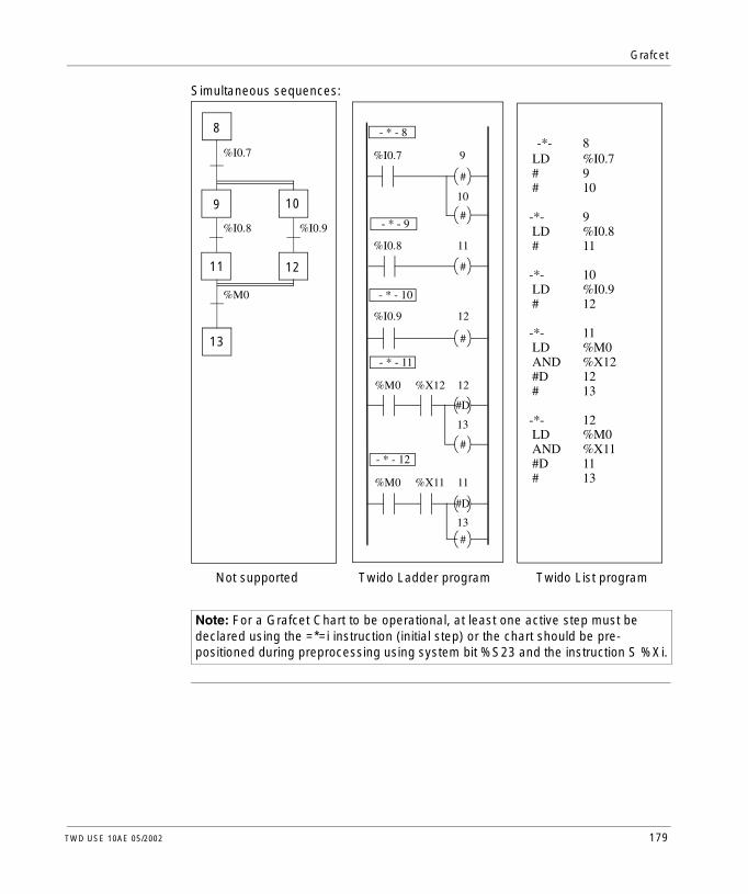
Grafcet
Simultaneous sequences:
Note: For a Grafcet Chart to be operational, at least one active step must be declared using the =*=i instruction (initial step) or the chart should be pre-positioned during preprocessing using system bit %S23 and the instruction S %Xi.
-*- 8 LD %I0.7 # 9 # 10 -*- 9 LD %I0.8 # 11 -*- 10 LD %I0.9 # 12 -*- 11 LD %M0 AND %X12 #D 12 # 13 -*- 12 LD %M0 AND %X11 #D 11 # 13
- * - 12
8
9 10
11 12
13
#
#
#
#
#
#
#D
#D
%I0.8
%I0.7
%I0.9
%M0
- * - 8
%I0.7
- * - 9
9
10
11%I0.8
- * - 10
%I0.9 12
12
- * - 11
%M0 %X12
13
11
13
%M0 %X11
Not supported Twido Ladder program Twido List program
TWD USE 10AE 05/2002 179

Grafcet
Description of Grafcet Program Structure
Introduction A TwidoSoft Grafcet program has three parts:l Preprocessingl Sequential processingl Post-processing
Preprocessing Preprocessing consists of the following:l Power returns l Faultsl Changes of operating model Pre-positioning Grafcet stepsl Input logicIn the preprocessing example below (the area prior to the first Grafcet step), state 0 of input %I0.6 prompts a reset of the Grafcet chart by setting system bit %S22 to 1. This deactivates the active steps. The rising edge of input %I0.6 pre-positions the chart to step X1. Finally, the use of system bit %S21 forces the initialization of Grafcet.
Preprocessing begins with the first line of the program and ends with the first occurrence of a "= * =" or "- * -" instruction.Three system bits are dedicated to Grafcet control: %S21, %S22, and %S23. Each of these system bits are set to 1 (if needed) by the application, normally in preprocessing. The associated function is performed by the system at the end of preprocessing and the system bit is then reset to 0 by the system.
System Bit Name Description
%S21 Grafcet Initialization
All active steps are deactivated and the initial steps are activated.
%S22 Reset Grafcet All steps are deactivated.
%S23 Grafcet Pre-positioning
This bit must be set to 1 if %Xi are explicitly written by the application in preprocessing. If this bit is maintained to 1 by the preprocessing without any explicit change of the %Xi objects, Grafcet is frozen (no updates are taken into account).
000 LDN %I0.6001 S %S22002 ST %M0003 LDR %I0.6004 S %S21
/
P S
S
%I0.6
%I0.6
%S22
%M0
%S21
180 TWD USE 10AE 05/2002

Grafcet
Sequential Processing
Sequential processing takes place in the chart (instructions representing the chart):l Steps l Actions associated with stepsl Transitionsl Transition conditionsExample:
Sequential processing ends with the execution of the "= * = POST" instruction or with the end of the program.
005 =*= 1006 LD %I0.2007 ANDN %I0.3008 # 2009 LD %I0.3010 ANDN %I0.2011 # 3012 -*- 2013 LD %I0.4014 # 1015 -*- 3016 LD %I0.5017 # 1
/
/
=*= 1
-*- 2
-*- 3
#
#
#
#
3
2
1
1%I0.5
%I0.4
%I0.3
%I0.3
%I0.2
%I0.2
TWD USE 10AE 05/2002 181

Grafcet
Post-Processing Post-processing consists of the following:l Commands from the sequential processing for controlling the outputsl Safety interlocks specific to the outputsExample:
018 =*= POST019 LD %X1020 ST %Q0.1021 LD %X2022 ST %Q0.2023 LD %X3024 OR( %M1025 ANDN %I0.2026 AND %I0.7027 ) 028 ST %Q0.3
/
%X1
%X2
%M1 %I0.2 %I0.7
%Q0.3
%Q0.2
%Q0.1
%X2
182 TWD USE 10AE 05/2002

Grafcet
Actions Associated with Grafcet Steps
Introduction A TwidoSoft Grafcet program offers two ways to program the actions associated with steps:l In the post-processing sectionl Within List instructions or Ladder rungs of the steps themselves
Associating Actions in Post-Processing
If there are security or running mode constraints, it is preferable to program actions in the post-processing section of a Grafcet application. You can use Set and Reset List instructions or energize coils in a Ladder program to activate Grafcet steps (%Xi).Example:
Associating Actions from an Application
You can program the actions associated with steps within List instructions or Ladder rungs. In this case, the List instruction or Ladder rung is not scanned unless the step is active. This is the most efficient, readable, and maintainable way to use Grafcet.Example:
018 =*= POST019 LD %X1020 ST %Q0.1021 LD %X2022 ST %Q0.2023 LD %X3024 ST %Q0.3
%X1
%X2
%Q0.3
%Q0.2
%Q0.1
%X2
-*- 4
#
R
S
-*- 3%Q0.5
%Q0.5
4
020021022023024025026027028029
-*-LDSLD#-*-LDR......
31%Q0.5%M10441%Q0.5
TWD USE 10AE 05/2002 183

Grafcet
184 TWD USE 10AE 05/2002

TWD USE 10AE 05/2002
IV
Description of Instructions and FunctionsAt a Glance
Overview This part provides detailed descriptions about basic and advanced instructions and system bits and words for Twido languages.
What’s in this Part?
This part contains the following chapters:
Chapter Chapter Name Page
12 Basic Instructions 187
13 Advanced Instructions 255
14 System Bits and System Words 317
185

Description of Instructions and Functions
186 TWD USE 10AE 05/2002

TWD USE 10AE 05/2002
12
Basic InstructionsAt a Glance
Overview This chapter provides details about instructions and function blocks that are used to create basic control programs for Twido controllers.
What’s in this Chapter?
This capter contains the following sections:
Section Topic Page
12.1 Boolean Processing 188
12.2 Basic Function Blocks 205
12.3 Numerical Processing 230
12.4 Program Instructions 248
187

Basic Instructions
12.1 Boolean Processing
Introduction to Boolean Processing
Overview This section provides an introduction to Boolean processing including descriptions and programming guidelines for Boolean instructions.
What’s in this Section?
This section contains the following topics:
Topic Page
Boolean Instructions 189
Understanding the Format for Describing Boolean Instructions 192
Load Instructions (LD, LDN, LDR, LDF) 194
Store Instructions (ST, STN, R, S) 196
Logical AND Instructions (AND, ANDN, ANDR, ANDF) 198
Logical OR Instructions (OR, ORN, ORR, ORF) 200
Exclusive OR Instructions (XOR, XORN, XORR, XORF) 202
NOT Instruction (N) 204
188 TWD USE 10AE 05/2002

Basic Instructions
Boolean Instructions
Introduction Boolean instructions can be compared to Ladder language elements as summarized in the following table.
The Boolean result of the test elements is applied to the action elements as shown by the following instructions.
Testing Controller Inputs
Boolean test instructions can be used to detect rising or falling edges on the controller inputs. An edge is detected when the state of an input has changed between "scan n-1" and the current "scan n", and it remains detected during the current scan.
Rising Edge Detection
The LDR instruction (Load Rising Edge) is equivalent to a rising edge detection contact. The rising edge detects a change of the controlling inputs from 0 to 1. A positive transition sensing contact is used to detect a rising edge as seen in the following diagram.
Element Instruction Example Description
Test elements The Load (LD) instruction is equivalent to an open contact.
LD %I0.0 Contact is closed when the controlling bit is at state 1.
Action elements The Store (ST) instruction is equivalent to a coil.
ST %Q0.0 The associated bit object takes a logical value of the bit accumulator (result of previous logic).
LD %I0.0AND %I0.1ST %Q0.0
LDR %I0.0
%I0.0
P: Positive transition sensing contactP
TWD USE 10AE 05/2002 189

Basic Instructions
Falling Edge Detection
The LDF instruction (Load Falling Edge) is equivalent to a falling edge detection contact. The falling edge detects a change of the controlling input from 1 to 0.A negative transition sensing contact is used to detect a falling edge as seen in the following diagram.
Edge Detection Timing
The following table summarizes the instructions and timing for the Boolean instructions used to test for rising and falling edges.
%I0.0
N: Negative transition sensing contactLDF %I0.0 N
Edge Test Instruction
Ladder Diagram
Timing
Rising edge LDR %I0.0
Falling edge LDF %I0.0
P
%I0.0Rising edge
time
time1 controller
scan
Booleanresult
%I0.2
N
%I0.0
time
time
Booleanresult
%I0.2
Falling edge
1 controller scan
190 TWD USE 10AE 05/2002
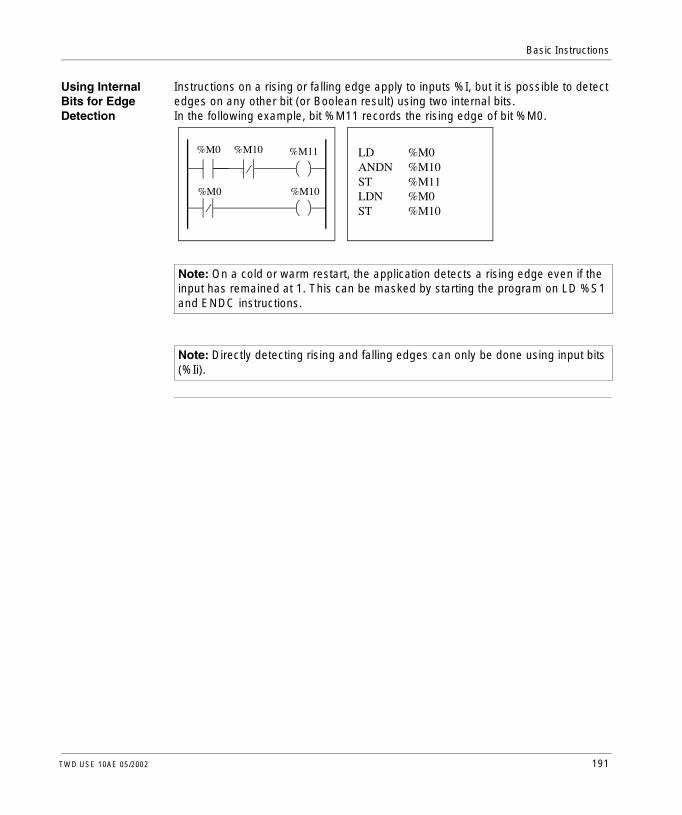
Basic Instructions
Using Internal Bits for Edge Detection
Instructions on a rising or falling edge apply to inputs %I, but it is possible to detect edges on any other bit (or Boolean result) using two internal bits.In the following example, bit %M11 records the rising edge of bit %M0.
Note: On a cold or warm restart, the application detects a rising edge even if the input has remained at 1. This can be masked by starting the program on LD %S1 and ENDC instructions.
Note: Directly detecting rising and falling edges can only be done using input bits (%Ii).
LD %M0ANDN %M10ST %M11LDN %M0ST %M10
%M0 %M10 %M11
%M0 %M10
TWD USE 10AE 05/2002 191

Basic Instructions
Understanding the Format for Describing Boolean Instructions
Introduction Each Boolean instruction in this section is described using the following information:l Brief descriptionl Example of the instruction and the corresponding ladder diagraml List of permitted operandsl Timing diagramThe following explanations provide more detail on how Boolean instructions are described in this section.
Examples The following illustration shows how examples are given for each instruction.
Permitted Operands
The following table defines the types of permitted operands used for Boolean instructions.
Ladder diagram equivalents List instructions
LD %I0.1ST %Q0.3LDN %M0ST %Q0.2LDR %I0.1ST %Q0.4LDF %I0.3ST %Q0.5
P
N
%I0.1
%M0
%I0.1
%I0.3
%Q0.3
%Q0.2
%Q0.4
%Q0.5
Operand Description
0/1 Immediate value of 0 or 1
%I Controller input %Ii.j
%Q Controller output %Qi.j
%M Internal bit %Mi
%S System bit %Si
%X Step bit %Xi
%BLK.x Function block bit (for example, %TMi.Q)
%•:Xk Word bit (for example, %MWi:Xk)
[ Comparison expression (for example, [%MWi<1000])
192 TWD USE 10AE 05/2002

Basic Instructions
Timing Diagrams The following illustration shows how timing diagrams are displayed for each instruction.
Timing diagram for theLD instruction
Input state
Output state
%M0 %I0.3%I0.1 %I0.2
LD LDN LDR LDF
%Q0.2 %Q0.5%Q0.3 %Q0.4
Timing diagrams for the four types of Load instructions are grouped together.
%I0.1
LD
%Q0.3
TWD USE 10AE 05/2002 193

Basic Instructions
Load Instructions (LD, LDN, LDR, LDF)
Introduction Load instructions LD, LDN, LDR, and LDF correspond respectively to the opened, closed, rising edge, and falling edge contacts (LDR and LDF are used only with controller inputs).
Examples The following diagrams are examples of Load instructions.
Permitted Operands
The following table lists the types of load instructions with Ladder equivalents and permitted operands.
N
LD %I0.1ST %Q0.3LDN %M0ST %Q0.2LDR %I0.2ST %Q0.4LDF %I0.3ST %Q0.5
P
%Q0.3
%Q0.2
%Q0.4
%Q0.5
%I0.1
%M0
%I0.2
%I0.3
List Instruction Ladder Equivalent Permitted Operands
LD 0/1,%I,%Q,%M,%S,%X,%BLK.x,%•:Xk,[
LDN %I,%Q,%M,%S,%X,%BLK.x,%•:Xk,[
LDR %I
LDF %I
P
N
194 TWD USE 10AE 05/2002

Basic Instructions
Timing Diagram The following diagram displays the timing for the Load instructions.
%M0 %I0.3%I0.1 %I0.2
LD LDN LDR LDF
%Q0.2 %Q0.5%Q0.3 %Q0.4
TWD USE 10AE 05/2002 195

Basic Instructions
Store Instructions (ST, STN, R, S)
Introduction The Store instructions ST, STN, S, and R correspond respectively to the direct, inverse, set, and reset coils.
Examples The following diagrams are examples of Store instructions.
Permitted Operands
The following table lists the types of Store instructions with Ladder equivalents and permitted operands.
LD %I0.1ST %Q0.3
STN %Q0.2S %Q0.4
LD %I0.2R %Q0.4
%Q0.3
%Q0.2
%Q0.4
%Q0.4%I0.2
%I0.1
R
S
/
List Instruction Ladder Equivalent Permitted Operands
ST %Q,%M,%S,%BLK.x,%•:Xk
STN %Q,%M,%S,%BLK.x,%•:Xk
S %Q,%M,%S,%X,%BLK.x,%•:Xk
R %Q,%M,%S,%X,%BLK.x,%•:Xk
S
R
196 TWD USE 10AE 05/2002

Basic Instructions
Timing Diagram The following diagram displays the timing for the Store instructions.
%I0.1 %I0.2%I0.1 %I0.1
ST STN S R
%Q0.2 %Q0.4%Q0.3 %Q0.4
TWD USE 10AE 05/2002 197

Basic Instructions
Logical AND Instructions (AND, ANDN, ANDR, ANDF)
Introduction The AND instructions perform a logical AND operation between the operand (or its inverse, or its rising or falling edge) and the Boolean result of the preceding instruction.
Examples The following diagrams are examples of logic AND instructions.
Permitted Operands
The following table lists the types of AND instructions with ladder equivalents and permitted operands.
LD %I0.1AND %M1ST %Q0.3LD %M2ANDN %I0.2ST %Q0.2LD %I0.3ANDR %I0.4S %Q0.4LD %M3ANDF %I0.5S %Q0.5
%Q0.3
%Q0.2
%Q0.4
%Q0.5
S
S
%I0.1
%I0.2
%I0.4%I0.3
%I0.5%M3
%M2
%M1
N
P
List Instruction Ladder Equivalent Permitted Operands
AND 0/1,%I,%Q,%M,%S,%X,%BLK.x,%•:Xk, [
ANDN %I,%Q,%M,%S,%X,%BLK.x,%•:Xk, [
ANDR %I
ANDF %I
P
N
198 TWD USE 10AE 05/2002

Basic Instructions
Timing Diagram The following diagram displays the timing for the AND instructions.
%M2 %M3%I0.1 %I0.3
AND ANDN ANDR ANDF
%I0.2 %I0.5%M1 %I0.4
%Q0.2%Q0.3 %Q0.4 %Q0.5
TWD USE 10AE 05/2002 199

Basic Instructions
Logical OR Instructions (OR, ORN, ORR, ORF)
Introduction The OR instructions perform a logical OR operation between the operand (or its inverse, or its rising or falling edge) and the Boolean result of the preceding instruction.
Examples The following diagrams are examples of logic OR instructions.
LD %I0.1OR %M1ST %Q0.3
LD %M2ORN %I0.2ST %Q0.2
LD %M3ORR %I0.4S %Q0.4
LDF %I0.5ORF %I0.6S %Q0.5
%Q0.3
%Q0.2
%Q0.4
%Q0.5
S
S
%I0.1
%M1
%I0.2
%I0.4
%I0.5
%I0.6
%M2
%M3
P
N
N
200 TWD USE 10AE 05/2002

Basic Instructions
Permitted Operands
The following table lists the types of OR instructions with Ladder equivalents and permitted operands.
Timing Diagram The following diagram displays the timing for the OR instructions.
List Instruction Ladder Equivalent Permitted Operands
OR 0/1,%I,%Q,%M,%S,%X,%BLK.x,%•:Xk
ORN %I,%Q,%M,%S,%X,%BLK.x,%•:Xk
ORR %I
ORF %I
P
N
%M2 %I0.5%I0.1 %M3
OR ORN ORR ORF
%I0.2 %I0.6%M1 %I0.4
%Q0.2%Q0.3 %Q0.4 %Q0.5
TWD USE 10AE 05/2002 201

Basic Instructions
Exclusive OR Instructions (XOR, XORN, XORR, XORF)
Introduction The XOR instructions perform an exclusive OR operation between the operand (or its inverse, or its rising or falling edge) and the Boolean result of the preceding instruction.
Examples The XOR instructions can be used as shown in the following examples.
Permitted Operands
The following table lists the types of XOR instructions and permitted operands.
LD %I0.1XOR %M1ST %Q0.3
LD %I0.1ANDN %M1OR( %M1ANDN %I0.1)ST %Q0.3
%Q0.3%M1%I0.1
XOR
%Q0.3
%I0.1
%I0.1
%M1
%M1
Instruction list Permitted Operands
XOR %I,%Q,%M,%S,%X,%BLK.x,%•:Xk
XORN %I,%Q,%M,%S,%X,%BLK.x,%•:Xk
XORR %I
XORF %I
202 TWD USE 10AE 05/2002

Basic Instructions
Timing Diagram The following diagram displays the timing for the XOR instructions.
Special Cases The following are special precautions for using XOR instructions in Ladder programs:l Do not insert XOR contacts in the first position of a rung.l Do not insert XOR contacts in parallel with other ladder elements (see the
following example.)As shown in the following example, inserting an element in parallel with the XOR contact will generate a validation error.
%I0.1
XOR
%M1
%Q0.3
%Q1.10
%M10
XOR
%I1.5%M13
TWD USE 10AE 05/2002 203

Basic Instructions
NOT Instruction (N)
Introduction The NOT (N) instruction negates the Boolean result of the preceding instruction.
Example The following is an example of using the NOT instruction.
Permitted Operands
Not applicable.
Timing Diagram The following diagram displays the timing for the NOT instruction.
Note: The NOT instruction is not reversible.
LD %I0.1OR %M2ST %Q0.2NAND %M3ST %Q0.3
%I0.1
NOT
%M2
%Q0.2
%M3
%Q0.3
204 TWD USE 10AE 05/2002

Basic Instructions
12.2 Basic Function Blocks
At a Glance
Overview This section provides descriptions and programming guidelines for using basic function blocks.
What’s in this Section?
This section contains the following topics:
Topic Page
Basic Function Blocks 206
Principles for Programming Basic Function Blocks 208
Timer Function Block (%TMi) 210
TOF Type of Timer 212
TON Type of Timer 213
TP Type of Timer 214
Programming and Configuring Timers 215
Up/Down Counter Function Block (%Ci) 218
Programming and Configuring Counters 222
Shift Bit Register Function Block (%SBRi) 223
Step Counter Function Block (%SCi) 226
TWD USE 10AE 05/2002 205

Basic Instructions
Basic Function Blocks
Introduction Function blocks are the sources for bit objects and specific words that are used by programs. Basic function blocks provide simple functions such as timers or up/down counting.
Example of a Function Block
The following illustration is an example of an up/down Counter function block.
Bit Objects Bit objects correspond to the block outputs. These bits can be accessed by Boolean test instructions using either of the following methods:l Directly (for example, LD E) if they are wired to the block in reversible
programming (see Principles for Programming Basic Function Blocks, p. 208).l By specifying the block type (for example, LD %Ci.E).Inputs can be accessed in the form of instructions.
Word Objects Word objects correspond to specified parameters and values as follows:l Block configuration parameters: Some parameters are accessible by the
program (for example, pre-selection parameters) and some are inaccessible by the program (for example, time base).
l Current values: For example, %Ci.V, the current count value.
Up/down counter block
R E
S D
CD F
CU
%Ci
ADJ Y
%Ci.P 9999
206 TWD USE 10AE 05/2002

Basic Instructions
Accessible Bit and Word Objects
The following table describes the Basic function blocks bit and word objects that can be accessed by the program.
Basic Function Block
Symbol Range (i) Types of Objects
Description Address Write Access
Timer %TMi 0 - 127 Word Current value %TMi.V no
Preset value %TMi.P yes
Bit Timer output %TMi.Q no
Up/Down counter
%Ci 0 - 31 Word Current value %Ci.V no
Preset value %Ci.P yes
Bit Underflow output (empty)
%Ci.E no
Preset output reached %Ci.D no
Overflow output (full) %Ci.F no
TWD USE 10AE 05/2002 207

Basic Instructions
Principles for Programming Basic Function Blocks
Introduction Use one of the following methods to program basic function blocks:l Function block instructions (for example, BLK %TM2): This reversible method of
programming ladder language enables operations to be performed on the block in a single place in the program.
l Specific instructions (for example, CU %Ci): This non-reversible method enables operations to be performed on the block’s inputs in several places in the program (for example, line 100 CU %C1, line 174 CD %C1, line 209 LD %C1.D).
Reversible Programming
Use instructions BLK, OUT_BLK, and END_BLK for reversible programming:l BLK: Indicates the beginning of the block.l OUT_BLK: Is used to directly wire the block outputs.l END_BLK: Indicates the end of the block.
Example with Wired Outputs
The following example shows reversible programming of a counter function block with wired outputs.
BLK %C8LDF %I1.1RLD %I1.2AND %M0CUOUT_BLKLD DAND %M1ST %Q0.4END_BLK
N
InputProcessing
OutputProcessing
R
S
CU
CD
E
D
F
%C8
ADJ Y%Ci.P 9999
%I1.1
%I1.2 %M0
%M1 %Q0.4
208 TWD USE 10AE 05/2002

Basic Instructions
Example without Output Wiring
This example shows reversible programming of a counter function block without wired outputs.
Note: Only test and input instructions on the relevant block can be placed between the BLK and OUT_BLK instructions (or between BLK and END_BLK when OUT_BLK is not programmed).
BLK %C8LDF %I1.1RLD %I1.2AND %M0CUEND_BLKLD %C8.DAND %M1ST %Q0.4
N R
S
CU
CD
E
D
F
%C8
ADJ Y%Ci.P 9999
%I1.1
%I1.2 %M0
%C8.D %M1 %Q0.4
InputProcessing
OutputProcessing
TWD USE 10AE 05/2002 209

Basic Instructions
Timer Function Block (%TMi)
Introduction There are three types of Timer function blocks:l TON (Timer On-Delay): Use this type of timer to control on-delay actions.l TOF (Timer Off-Delay): Use this type of timer to control off-delay actions.l TP (Timer - Pulse): Use this type of timer to create a pulse of a precise duration.The delays or pulse periods are programmable and may be modified using the TwidoSoft.
Illustration The following is an illustration of the Timer function block.
TYPE TONTB 1minADJ Y%TMi.P 9999
Timer function block
QIN
%TMi
210 TWD USE 10AE 05/2002

Basic Instructions
Parameters The Timer function block has the following parameters:
Parameter Label Value
Timer number %TMi 0 to 63 Compact Controller0 to 127 Modular Controllers
Type TON • on-delay (by default)
TOF • off-delay
TP • pulse (monostable)
Time base TB 1 min (default), 1s, 100ms, 10ms, 1ms (for TM0 and TM1).
Current value %TMi.V Word which increments from 0 to %TMi.P when the timer is running. May be read and tested, but not written by the program. %TMi.V can be modified using the Data Editor.
Preset value %TMi.P 0 - 9999. Word which may be read, tested, and written by the program. Default value is 9999. The period or delay generated is equal to %TMi.P x TB.
Data Editor Y/N Y: Yes, the preset %TMi.P value can be modified using the Data Editor.N: No, the preset %TMi.P value cannot be modified.
Setting Input (or instruction)
IN Starts the timer on rising edge (TON or TP types) or falling edge (TOF type).
Timer output Q Associated bit %TMi.Q is set to 1 depending on the function performed: TON, TOF, or TP.1.
Note: The larger the preset value, the greater the timer accuracy.
TWD USE 10AE 05/2002 211

Basic Instructions
TOF Type of Timer
Introduction Use the TOF (Timer Off-Delay) type of timer to control off-delay actions. This delay is programmable using TwidoSoft.
Timing Diagram The following timing diagram illustrates the operation of the TOF type timer.
Operation The following table describes the operation of the TOF type timer.
IN
Q
%TMi.P
%TMi.V
(1)
(3)
(4)
(2)
(5)
(1)
Phase Description
1 The current value %TMi.V is set to 0 on a rising edge at input IN, even if the timer is running.
2 The %TMi.Q output bit is set to 1 when a rising edge is detected at input N.
3 The timer starts on the falling edge of input IN.
4 The current value %TMi.V increases to %TMi.P in increments of one unit for each pulse of the time base TB.
5 The %TMi.Q output bit is reset to 0 when the current value reaches %TMi.P.
212 TWD USE 10AE 05/2002

Basic Instructions
TON Type of Timer
Introduction The TON (Timer On-Delay) type of timer is used to control on-delay actions. This delay is programmable using the TwidoSoft.
Timing Diagram The following timing diagram illustrates the operation of the TON type timer.
Operation The following table describes the operation of the TON type timer.
IN
Q
%TMi.P
%TMi.V
(1)
(3)
(4)
(2)
(5)
Phase Description
1 The timer starts on the rising edge of the IN input.
2 The current value %TMi.V increases from 0 to %TMi.P in increments of one unit for each pulse of the time base TB.
3 The %TMi.Q output bit is set to 1 when the current value has reached %TMi.P.
4 The %TMi.Q output bit remains at 1 while the IN input is at 1.
5 When a falling edge is detected at the IN input, the timer is stopped, even if the timer has not reached %TMi.P, and %TMi.V is set to 0.
TWD USE 10AE 05/2002 213

Basic Instructions
TP Type of Timer
Introduction The TP (Timer - Pulse) type of timer is used to create pulses of a precise duration. This delay is programmable using the TwidoSoft.
Timing Diagram The following timing diagram illustrates the operation of the TP type timer.
Operation The following table describes the operation of the TP type timer.
IN
Q
%TMi.P
%TMi.V
(1)
(3)
(4)
(5)
(2) (6)
Phase Description
1 The timer starts on the rising edge of the IN input. The current value %TMi.V is set to 0 if the timer has not already started.
2 The %TMi.Q output bit is set to 1 when the timer starts.
3 The current value %TMi.V of the timer increases from 0 to %TMi.P in increments of one unit per each pulse of the time base TB.
4 The %TMi.Q output bit is set to 0 when the current value reaches %TMi.P.
5 The current value %TMi.V is set to 0 when %TMi.V equals %TMi.P and input IN returns to 0.
6 This timer cannot be reset. Once %TMi.V equals %TMi.P, and input IN is 0, then %TMi.V is set to 0.
214 TWD USE 10AE 05/2002

Basic Instructions
Programming and Configuring Timers
Introduction Timer function blocks (%TMi) are programmed in the same way regardless of how they are to be used. The timer function (TON, TOF, or TP) is selected during configuration.
Examples The following illustration is a timer function block with examples of reversible and non-reversible programming.
Configuration The following parameters must be entered during configuration:l Timer type: TON, TOF, or TPl Time base (TB): 1 min, 1s, 100 ms, 10 ms, or 1 msl Preset value (%TMi.P): 0 to 9999l Adjust: Yes or No (Y or N)
BLK %TM1LD %I0.1INOUT_BLKLD QST %Q0.3END_BLK
LD %I0.1IN %TM1LD %TM1.QST %Q0.3
Reversible programming Non-Reversible programming
TYPE TONTB 1minADJ Y%TMi.P 9999
%I0.1 %Q0.3%TMi
IN Q
TWD USE 10AE 05/2002 215

Basic Instructions
Special Cases The following table contains a list of special cases of programming and configuring timers.
Timers with a 1ms Time Base
The 1 ms time base is only available on %TM0 and %TM1 timers. The four system words %SW76, %SW77, %SW78, and SW79, can be used as "hourglasses." These four words are decremented individually by the system every millisecond if they have a positive value.Multiple timing can be achieved by successive loading of one of these words or by testing the intermediate values. If the value of one of these four words is less than 0, it will not be modified. A timer can be "frozen" by setting the corresponding bit 15 to 1, and then "unfrozen" by resetting it to 0.
Special Case Description
Effect of a cold restart (%S0=1) Forces the current value to 0. Sets output %TMi.Q to 0. The preset value is reset to the value defined during configuration.
Effect of a warm restart (%S1=1) Has no effect on the current and preset values of the timer. The current value does not change during a power outage.
Effect of a controller stop Stopping the controller does not freeze the current value.
Effect of a program jump Jumping over the timer block does not freeze the timer. The timer will continue to increment until it reaches the preset value (%TMi.P). At that point, the Done bit (%TMi.Q) assigned to output Q of the timer block changes state; however, the associated output wired directly to the block output is not activated and not scanned by the controller.
Testing by bit %TMi.Q (done bit) It is advisable to test bit %TMi.Q only once in the program.
Effect of modifying the preset %TMi.P Modifying the present value by using an instruction or by adjusting the value only takes effect on the next activation of the timer.
216 TWD USE 10AE 05/2002

Basic Instructions
Programming Example
The following is an example of programming a timer function block.
LDR %I0.1 (Launching the timer on the rising edge of %I0.1)[%SW76:=XXXX] (XXXX = required value)LD %I0.2 (optional management of freeze, input I0.2 freezes)ST %SW76:X15LD [%SW76=0] (timer end reset)ST %M0..............
%I0.1
%SW76:=XXXX
%I0.2
%SW76=0
%M0
%SW76:X15
P
TWD USE 10AE 05/2002 217

Basic Instructions
Up/Down Counter Function Block (%Ci)
Introduction The Counter function block (%Ci) provides up and down counting of events. These two operations can be done simultaneously.
Illustration The following is an illustration of the up/down Counter function block.
ADJ Y%TMi.P 9999
Up/down counter function block
R E
S D
CD F
CU
%Ci
218 TWD USE 10AE 05/2002

Basic Instructions
Parameters The Counter function block has the following parameters:
Parameter Label Value
Counter number %Ci 0 to 31
Current value %Ci.V Word is incremented or decremented according to inputs (or instructions) CU and CD. Can be read and tested but not written by the program. Use the Data Editor to modify %Ci.V.
Preset value %Ci.P 0 - %Ci.P-9999. Word can be read, tested, and written (default value: 9999).
Edit using the Data Editor
Y/N l Y: Yes, the preset value can be modified by using the Data Editor.
l N: No, the preset value cannot be modified by using the Data Editor.
Reset input (or instruction)
R At state 1: %Ci.V = 0.
Set input (or instruction)
S At state 1: %Ci.V = %Ci.P.
Upcount input (or instruction)
CU Increments %Ci.V on a rising edge.
Downcount input (or instruction)
CD Decrements %Ci.V on a rising edge.
Underflow output E (Empty) The associated bit %Ci.E=1, when down counter %Ci.V changes from 0 to 9999 (set to 1 when %Ci.V reaches 9999, and reset to 0 if the counter continues to count down).
Preset output reached D (Done) The associated bit %Ci.D=1, when %Ci.V=%Ci.P.
Overflow output F (Full) The associated bit %Ci.F=1, when %Ci.V changes from 9999 to 0 (set to 1 when %Ci.V reaches 0, and reset to 0 if the counter continues to count up).
TWD USE 10AE 05/2002 219

Basic Instructions
Operation The following table describes the main stages of up/down counter operation.
Operation Action Result
Upcount A rising edge appears at the upcounting input CU (or instruction CU is activated).
The %Ci.V current value is incremented by one unit.
The %Ci.V current value is equal to the %Ci.P preset value.
The "preset reached" output bit %Ci.D assigned to output D changes to state 1.
The %Ci.V current value changes from 9999 to 0.
The output bit %Ci.F (Upcount overflow) changes to state 1.
If the counter continues to count up.
The output bit %Ci.F (Upcount overflow) is reset to 0.
Downcount A rising edge appears at the downcounting input CD (or instruction CD is activated).
The current value %Ci.V is decremented by one unit.
The current value %Ci.V changes from 0 to 9999.
The output bit %Ci.E (underflow) changes to state 1.
If the counter continues to count down.
The output bit %Ci.E (underflow) is reset to 0.
Up/down count To use both the upcount and downcount functions simultaneously (or to activate both instructions CD and CU), the two corresponding inputs CU and CD must be controlled. These two inputs are then scanned in succession, If they are both at 1, the current value remains unchanged.
Reset Input R is set to state 1(or the R instruction is activated).
The current value%Ci.V is forced to 0. Outputs %Ci.E, %Ci.D and %Ci.F are at 0. The reset input has priority.
Set If input S is at state 1 (or the S instruction is activated) and the reset input is at 0 (or the R instruction is inactive).
The current value %Ci.V takes the %Ci.P value and the %Ci.D output is set to 1.
220 TWD USE 10AE 05/2002

Basic Instructions
Special Cases The following table contains a list of special cases of programming and configuring counters.
Special Case Description
Effect of a cold restart (%S0=1) l The current value %Ci is set to 0.l Output bits %Ci.E, %Ci.D, and %Ci.F are set to
0.l The preset value is initialized with the value
defined during configuration.
Effect of a warm restart (%S1=1) of a controller stop
Has no effect on the current value of the counter (%Ci.V).
Effect of modifying the preset %Ci.P Modifying the preset value via an instruction or by adjusting it takes effect when the block is processed by the application (activation of one of the inputs).
TWD USE 10AE 05/2002 221

Basic Instructions
Programming and Configuring Counters
Introduction The following example is a counter that provides a count of items up to 5000. Each pulse on input %I1.2 (when internal bit %M0 is at 1) increments the counter %C8 up to its final preset value (bit %C8.D=1). The counter is reset by input %I1.1.
Programming Example
The following illustration is a counter function block with examples of reversible and non-reversible programming.
Configuration The following parameters must be entered during configuration:l Preset value (%Ci.P): set to 5000 in this examplel Adjust: Yes
BLK %C8LD %I1.1RLD %I1.2AND %M0CUEND_BLKLD %C8.DST %Q0.0
R
S
CU
CD
E
D
F
%C8
ADJ Y%Ci.P 9999
%I1.1
%I1.2 %M0
%C8.D %Q0.0
Reversible programming Non-reversible programming
Ladder diagram
LD %I1.1R %C8LD %I1.2AND %M0CU %C8LD %C8.DST %Q0.0
222 TWD USE 10AE 05/2002

Basic Instructions
Shift Bit Register Function Block (%SBRi)
Introduction The Shift Bit Register function block (%SBRi) provides a left or right shift of binary data bits (0 or 1).
Illustration The following is an example of a Shift Register function block.
Parameters The Shift Bit Register function block has the following parameters.
%SBRiR
CU
CD
Parameter Label Value
Register number %SBRi 0 to 7
Register bit %SBRi.j Bits 0 to 15 (j = 0 to 15) of the shift register can be tested by a Test instruction and written using an Assignment instruction.
Reset input (or instruction)
R On a rising edge, sets register bits 0 to 15 %SBRi.j to 0.
Shift to left input (or instruction)
CU On a rising edge, shifts a register bit to the left.
Shift to right input (or instruction)
CD On a rising edge, shifts a register bit to the right.
TWD USE 10AE 05/2002 223

Basic Instructions
Operation The following illustration shows a bit pattern before and after a shift operation.
This is also true of a request to shift a bit to the right (Bit 15 to Bit 0) using the CD instruction. Bit 0 is lost.If a 16-bit register is not adequate, it is possible to use the program to cascade several registers.
Programming In the following example, a bit is shifted to the left every second while Bit 0 assumes the opposite state to Bit 15.
Bit 15 Bit 0
Bit 15 Bit 0
OperationInitial state
CU %SBRi performs ashift to the left
Bit 15 is lost
1 1 1 1 1 1 1
1 1 1 1 10
0 0 0 0 0 0 0 0 0
000000000 1
LDN %SBR0.15ST %SBR0.0BLK %SBR0LD %S6CUEND_BLK
LDN %SBR0.15ST %SBR0.0LD %S6CU %SBR0
Reversible programming
Non-Reversible programming
%SBR0.0%SBR0.15
/
%SBR0R
CU
CD
%S6
224 TWD USE 10AE 05/2002

Basic Instructions
Special Cases The following table contains a list of special cases for programming the Shift Bit Register function block.
Special Case Description
Effect of a cold restart (%S0=1) Sets all the bits of the register word to 0.
Effect of a warm restart (%S1=1) Has no effect on the bits of the register word.
TWD USE 10AE 05/2002 225

Basic Instructions
Step Counter Function Block (%SCi)
Introduction A Step Counter function block (%SCi) provides a series of steps to which actions can be assigned. Moving from one step to another depends on external or internal events. Each time a step is active, the associated bit is set to 1. Only one step of a step counter can be active at a time.
Illustration The following is an example of a Step Counter function block.
Parameters The Step Counter function block has the following parameters.
%SCiR
CU
CD
Parameter Label Value
Step counter number %SCi 0 to 7
Step counter bit %SCi.j Step counter bits 0 to 255 (j = 0 to 255) can be tested by a Load logical operation and written by an Assignment instruction.
Reset input (or instruction)
R On a rising edge, resets the step counter.
Increment input (or instruction)
CU On a rising edge, increments the step counter by one step.
Decrement input (or instruction)
CD On a rising edge, decrements the step counter by one step.
226 TWD USE 10AE 05/2002

Basic Instructions
Timing Diagram The following diagram illustrates the operation of the Step Counter function block.
CU input
CD input
N inactive 0 1 2 3 2 1 0
TWD USE 10AE 05/2002 227

Basic Instructions
Programming The following is an example of a Step Counter function block. l Step Counter 0 is incremented by input %I0.2.l Step Counter 0 is reset to 0 by input %I0.3 or when it arrives at step 3.l Step 0 controls output %Q0.1, step 1 controls output %Q0.2, and step 2 controls
output %Q0.3.The following illustration shows both reversible and non-reversible programming for this example.
BLK %SC0LD %SC0.3OR %I0.3RLD %I0.2CUEND_BLKLD %SC0.0ST %Q0.1LD %SC0.1ST %Q0.2LD %SC0.2ST %Q0.3
LD %SC0.3OR %I0.3R %SC0LD %I0.2CU %SC0LD %SC0.0ST %Q0.1LD %SC0.1ST %Q0.2LD %SC0.2ST %Q0.3
Reversible programming
Non-Reversible programming
%SC0.3
%I0.3
%I0.2
%SC0
R
CU
CD
%Q0.1%SC0.0
%SC0.1
%SC0.2
%Q0.2
%Q0.3
228 TWD USE 10AE 05/2002

Basic Instructions
Special Cases The following table contains a list of special cases for programming the Step Counter function block.
Special Case Description
Effect of a cold restart (%S0=1) Initializes the step counter.
Effect of a warm restart (%S1=1) Has no effect on the step counter.
TWD USE 10AE 05/2002 229

Basic Instructions
12.3 Numerical Processing
Introduction to Numerical Processing
Overview This section provides an introduction to Numerical Processing including descriptions and programming guidelines.
What’s in this Section?
This section contains the following topics:
Topic Page
Introduction to Numerical Instructions 231
Assignment Instructions 232
Comparison Instructions 236
Arithmetic Instructions 238
Logic Instructions 242
Shift Instructions 244
Conversion Instructions 246
230 TWD USE 10AE 05/2002

Basic Instructions
Introduction to Numerical Instructions
Overview Numerical instructions generally apply to 16-bit words (see Word Objects, p. 27). They are written between square brackets. If the result of the preceding logical operation was true (Boolean accumulator = 1), the numerical instruction is executed. If the result of the preceding logical operation was false (Boolean accumulator = 0), the numerical instruction is not executed and the operand remains unchanged.
TWD USE 10AE 05/2002 231

Basic Instructions
Assignment Instructions
Introduction Assignment instructions are used to load operand Op2 into operand Op1.
Assignment Syntax for Assignment instructions.
Assignment operations can be performed on:l Bit stringsl Wordsl Word tables
Assignment of Bit Strings
Operations can be performed on the following bit strings (see Structured Objects, p. 35):l Bit string -> bit string (Example 1)l Bit string -> word (Example 2)l Word -> bit string (Example 3)l Immediate value -> bit string
Examples Examples of bit string assignments.
Usage rules:l For bit string -> word assignment: The bits in the string are transferred to the word
starting on the right (first bit in the string to bit 0 in the word), and the word bits which are not involved in the transfer (length<16) are set to 0.
l For word -> bit string assignment: The word bits are transferred from the right (word bit 0 to the first bit in the string).
[Op1:=Op2] <=> Op2 -> Op1
LD 1[%Q0:8:=%M64:8]
LD %I0.2[%MW100:=%I0:16]
LDR %I0.3[%M104:16:=%KW0]
(Ex. 1)
(Ex. 2)
(Ex. 3)
%Q0:8:=%MW64:8
%MW100:=%I0:16
%MW104:16:=%KW0
%I0.2
%I0.3
P
232 TWD USE 10AE 05/2002

Basic Instructions
Bit String Assignments
Syntax for bit string assignments.
Assignment of Words
Assignment operations can be performed on the following words:l Word -> word (Example 1)l Indexed word -> wordl Immediate value -> word (Example 3)l Bit string -> wordl Word -> indexed wordl Indexed word -> indexed word (Example 2)l Immediate value -> indexed word l Word -> bit string
Examples Examples of word assignments.
Operator Syntax Operand 1 (Op1) Operand 2 (Op2)
:= [Op1: = Op2 ]
Operand 1 (Op1) assumes the value of operand 2 (Op2)
%MWi,%QWi, %SWi %MWi[MWi], %Mi:L, %Qi:L, %Si:L, %Xi:L
Immediate value, %MWi, %KWi, %IW, %INWi, %QW, %QNWi, %SWi, %BLK.x, %MWi[MWi], %KWi[MWi], %Mi:L,%Qi:L, %Si:L, %Xi:L, %Ii:L
Note: The abbreviation %BLK.x (for example, %C0.P) is used to describe any function block word.
LD 1[%SW112:=%MW100]
LD %I0.2[%MW0[%MW10]:=] %KW0[%MW20]
LDR %I0.3[%MW10:=100]
(Ex. 1)
(Ex. 2)
(Ex. 3)
%SW112:=%MW100
%MW0[%MW10]:=%KW0[%MW20]
%MW10:=100
%I0.3
%I0.2
P
TWD USE 10AE 05/2002 233

Basic Instructions
Syntax Syntax for word assignments.
Assignment of Word Tables
Assignment operations can be performed on the following word tables (see Word Tables, p. 36):l Immediate value -> word table (Example 1) l Word -> word table (Example 2)l Word table -> word table (Example 3)
Table length (L) should be the same for both tables.
Examples Examples of word table assignments:
Operator Syntax Operand 1 (Op1) Operand 2 (Op2 )
:= [Op1: = Op2 ]
Operand 1 (Op1) assumes the value of operand 2 (Op2)
%BLK.x, %MWi, %QWi, %SWi %MWi[MWi], %Mi:L, %Qi:L, %Si:L, %Xi:L
Immediate value, %MWi, %KWi, %IW, %QW, %SWi, %MWi[MWi], %KWi[MWi], %INW, %Mi:L, %Qi:L, %QNW, %Si:L, %Xi:L, %Ii:L
Note: The abbreviation %BLK.x (for example, R3.I) is used to describe any function block word. For bit strings %Mi:L, %Si:L, and %Xi:L, the base address of the first of the bit string must be a multiple of 8 (0, 8, 16, ..., 96, ...).
LD 1[%MW0:10:=100]
LD %I0.2[%MW0:10:=%MW11]
LDR %I0.3[%MW10:20:=%KW30:20]
(Ex. 1)
(Ex. 2)
(Ex. 3)
%MW0:10:=100
%MW0:10:=%MW11
%MW10:20:=%KW30:20
%I0.2
%I0.3
P
234 TWD USE 10AE 05/2002
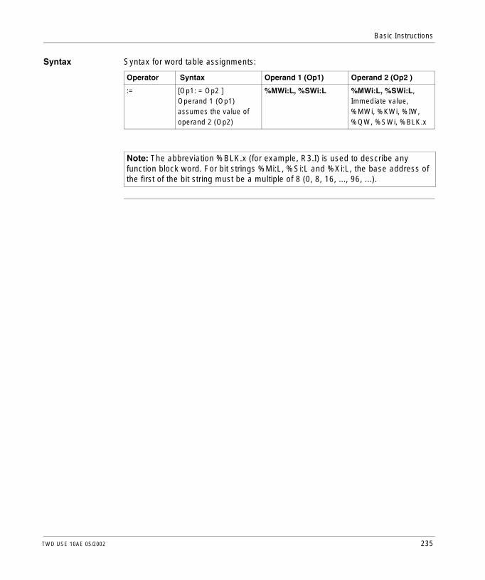
Basic Instructions
Syntax Syntax for word table assignments:
Operator Syntax Operand 1 (Op1) Operand 2 (Op2 )
:= [Op1: = Op2 ] Operand 1 (Op1) assumes the value of operand 2 (Op2)
%MWi:L, %SWi:L %MWi:L, %SWi:L, Immediate value, %MWi, %KWi, %IW, %QW, %SWi, %BLK.x
Note: The abbreviation %BLK.x (for example, R3.I) is used to describe any function block word. For bit strings %Mi:L, %Si:L and %Xi:L, the base address of the first of the bit string must be a multiple of 8 (0, 8, 16, ..., 96, ...).
TWD USE 10AE 05/2002 235

Basic Instructions
Comparison Instructions
Introduction Comparison instructions are used to compare two operands.The following table lists the types of Comparison instructions.
Structure The comparison is executed inside square brackets following instructions LD, AND, and OR. The result is 1 when the comparison requested is true.Examples of Comparison instructions.
Instruction Function
> Test if operand 1 is greater than operand 2
>= Test if operand 1 is greater than or equal to operand 2
< Test if operand 1 is less than operand 2
<= Test if operand 1 is less than or equal to than operand 2
= Test if operand 1 is equal than operand 2
<> Test if operand 1 is different than operand 2
LD [%MW10 > 100]ST %Q0.3
LD %M0AND [%MW20 < %KW35]ST %Q0.2
LD %I0.2OR [%MW30>=%MW40]ST %Q0.4
%Q0.3
%Q0.2
%Q0.4
%M0
%I0.2
%MW10>100
%MW20<%KW35
%MW30>=%MW40
236 TWD USE 10AE 05/2002

Basic Instructions
Syntax Syntax for Comparison instructions.
An example of using Comparison instruction within parentheses:
Operator Syntax Operand 1 (Op1) Operand 2 (Op2)
>, >=, <, <=, =, <>
LD [Op1 Operator Op2]AND [Op1 Operator Op2]OR [Op1 Operator Op2]
%MWi, %KWi, %INWi, %IW, %QNWi, %QWi, %QNWi, %SWi, %BLK.x
Immediate value, %MWi, %KWi, %INWi, %IW, %QNWi, %QW, %SWi, %BLK.x, %MWi [%MWi], %KWi [%MWi]
Note: Comparison instructions can be used within parentheses.
LD %M0AND( [%MW20 > 10]OR %I0.0)ST %Q0.1
TWD USE 10AE 05/2002 237

Basic Instructions
Arithmetic Instructions
Introduction Arithmetic instructions are used to perform arithmetic operations between two operands or on one operand.The following table lists the types of Arithmetic instructions.
Structure Arithmetic operations are performed as follows:
Instruction Function
+ Add two operands
- Subtract two operands
* Multiply two operands
/ Divide two operands
REM Remainder of division of the two operands
SQRT Square root of an operand
INC Increment an operand
DEC Decrement an operand
LD %M0[%MW0:=%MW10 + 100]
LD %I0.2[%MW0:=SQRT(%MW10)]
LDR %I0.3[INC %MW100]
%I0.3
P
%I0.2
%M0
%MW0:=%MW10+100
%MW0:=SQRT(%MW10)
INC %MW100
238 TWD USE 10AE 05/2002

Basic Instructions
Syntax The syntax depends on the operators used as shown in the table below.
Operator Syntax Operand 1 (Op1) Operands 2 and 3 (Op2 & 3)
+,-,*,/,REM [Op1: = Op 2 Operator Op3] %MWi, %QWi, %SWi
Immed.value (2), %MWi, %KWi, %INW, %IW, %QNW, %QW, %SWi, %BLK.x
SQRT (1) [Op1: = SQRT(Op2)]
INC, DEC [Operator Op1]
Note: (1) With SQRT, Op2 cannot be an immediate value.
TWD USE 10AE 05/2002 239
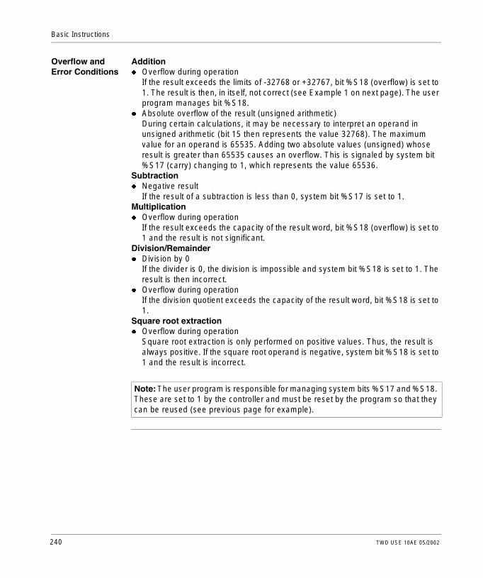
Basic Instructions
Overflow and Error Conditions
Additionl Overflow during operation
If the result exceeds the limits of -32768 or +32767, bit %S18 (overflow) is set to 1. The result is then, in itself, not correct (see Example 1 on next page). The user program manages bit %S18.
l Absolute overflow of the result (unsigned arithmetic)During certain calculations, it may be necessary to interpret an operand in unsigned arithmetic (bit 15 then represents the value 32768). The maximum value for an operand is 65535. Adding two absolute values (unsigned) whose result is greater than 65535 causes an overflow. This is signaled by system bit %S17 (carry) changing to 1, which represents the value 65536.
Subtractionl Negative result
If the result of a subtraction is less than 0, system bit %S17 is set to 1.Multiplicationl Overflow during operation
If the result exceeds the capacity of the result word, bit %S18 (overflow) is set to 1 and the result is not significant.
Division/Remainderl Division by 0
If the divider is 0, the division is impossible and system bit %S18 is set to 1. The result is then incorrect.
l Overflow during operationIf the division quotient exceeds the capacity of the result word, bit %S18 is set to 1.
Square root extractionl Overflow during operation
Square root extraction is only performed on positive values. Thus, the result is always positive. If the square root operand is negative, system bit %S18 is set to 1 and the result is incorrect.
Note: The user program is responsible for managing system bits %S17 and %S18. These are set to 1 by the controller and must be reset by the program so that they can be reused (see previous page for example).
240 TWD USE 10AE 05/2002
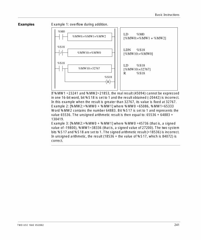
Basic Instructions
Examples Example 1: overflow during addition.
If %MW1 =23241 and %MW2=21853, the real result (45094) cannot be expressed in one 16-bit word, bit %S18 is set to 1 and the result obtained (-20442) is incorrect. In this example when the result is greater than 32767, its value is fixed at 32767.Example 2: [%MW2:=%MW0 + %MW1] where %MW0 =65086, %MW1=65333 Word %MW2 contains the number 64883. Bit %S17 is set to 1 and represents the value 65536. The unsigned arithmetic result is then equal to: 65536 + 64883 = 130419.Example 3: [%MW2:=%MW0 + %MW1] where %MW0 =45736 (that is, a signed value of -19800), %MW1=38336 (that is, a signed value of 27200). The two system bits %S17 and %S18 are set to 1. The signed arithmetic result (+18536) is incorrect. In unsigned arithmetic, the result (18536 + the value of %S17, which is 84072) is correct.
LD %M0[%MW0:=%MW1 + %MW2]
LDN %S18[%MW10:=%MW0]
LD %S18[%MW10:=32767]R %S18
%M0
%S18
%S18
%MW0:=%MW1+%MW2
%MW10:=%MW0
%MW10:=32767
%S18
R
/
TWD USE 10AE 05/2002 241

Basic Instructions
Logic Instructions
Introduction The Logic instructions are used to perform a logical operation between two word operands or on one word operand.The following table lists the types of Logic instructions.
Structure Logic operations are performed as follows:
Instruction Function
AND AND (bit-wise) between two operands
OR Logic OR (bit-wise) between two operands
XOR Exclusive OR (bit-wise) between two operands
NOT Logic complement (bit-wise) of an operand
LD %M0[%MW0:=%MW10 AND 16#FF00]
LD 1[%MW0:=%KW5 OR %MW10]
LD %I0.3[%MW102:=NOT(%MW100)]
%M0
%I0.3
%MW0:=%MW10 AND 16#FF00
%MW0:=%KW5 OR %MW10
%MW102:=NOT (%MW100)
242 TWD USE 10AE 05/2002

Basic Instructions
Syntax The syntax depends on the operators used:
Example The following is an example of a logical AND instruction:[%MW15:=%MW32 AND %MW12]
Operator Syntax Operand 1 (Op1) Operands 2 and 3 (Op2 & 3)
AND, OR, XOR [Op1: = Op 2 Operator Op3] %MWi, %QWi, %SWi
Immed.value (1), %MWi, %KWi, %IW, %QW, %SWi, %BLK.x
NOT [NOT(Op2)]
Note: (1) With NOT, Op2 cannot be an immediate value.
TWD USE 10AE 05/2002 243

Basic Instructions
Shift Instructions
Introduction Shift instructions move bits of an operand a certain number of positions to the right or to the left.The following table lists the types of Shift instructions.
Instruction Function
Logic shift
SHL(op2,i) logic shift of i positions to the left.
SHR(op2,i) logic shift of i positions to the right.
Rotate shift
ROL(op2,i) rotate shift of i positions to the left.
ROR(op2,i) rotate shift of i positions to the right.
F 0
%S17
F 0
%S17
F 0
F 0
%S17
%S17
244 TWD USE 10AE 05/2002

Basic Instructions
Structure Shift operations are performed as follows:
Syntax The syntax depends on the operators used as shown in the table below.
LDR %I0.1[%MW0 :=SHL(%MW10.5)]
LDR %I0.2[%MW10 :=ROR(%KW9.8)]
%I0.2
P
P %MW0:=SHL(%MW10.5)
%MW10:=ROR(%KW9.8)
%I0.1
Operator Syntax Operand 1 (Op1) Operand 2 (Op2)
SHL, SHR [Op1: = Operator (Op2,i)] %MWi, %QWi, %SWi
%MWi, %KWi, %IW, %QW, %SWi, %BLK.x
ROL, ROR
TWD USE 10AE 05/2002 245

Basic Instructions
Conversion Instructions
Introduction Conversion instructions perform conversion between different representations of numbers.The following table lists the types of Conversion instructions.
Review of BCD Code
Binary Coded Decimal (BCD) represents a decimal digit (0 to 9) by coding four binary bits. A 16-bit word object can thus contain a number expressed in four digits (0000 - 9999).During a conversion, if the value is not BCD, the system bit %S18 is set to 1. This bit must be tested and reset to 0 by the program.BCD representation of decimal numbers:
Examples:l Word %MW5 expresses the BCD value "2450" which corresponds to the binary
value: 0010 0100 0101 0000l Word %MW12 expresses the decimal value "2450" which corresponds to the
binary value: 0000 1001 1001 0010Word %MW5 is converted to word %MW12 by using instruction BTI. Word %MW12 is converted to word %MW5 by using instruction ITB.
Structure Conversion operations are performed as follows:
Instruction Function
BTI BCD --> Binary conversion
ITB Binary --> BCD conversion
Decimal 0 1 2 3 4 5 6 7 8 9
BCD 0000 0001 0010 0011 0100 0101 0110 0111 1000 1001
LD %M0[%MW0 :=BTI(%MW10)]
LD %I0.2[%MW10 :=ITB(%KW9)]
%I0.2
%M0
%MW0:=BTI(%MW10)
%MW10:=ITB(%KW9)
246 TWD USE 10AE 05/2002

Basic Instructions
Syntax The syntax depends on the operators used as shown in the table below.
Application Examples
The BTI instruction is used to process a setpoint value at controller inputs via BCD encoded thumb wheels. The ITB instruction is used to display numerical values (for example, the result of a calculation, the current value of a function block) on BCD coded displays.
Operator Syntax Operand 1 (Op1) Operand 2 (Op2)
BTI, ITB [Op1: = Operator (Op2,i)] %MWi, %QWi, %SWi
%MWi, %KWi, %IW, %QW, %SWi, %BLK.x
TWD USE 10AE 05/2002 247

Basic Instructions
12.4 Program Instructions
Introduction to Program Instructions
Overview This section provides an introduction to Program Instructions.
What’s in this Section?
This section contains the following topics:
Topic Page
END Instructions 249
NOP Instruction 251
Jump Instructions 252
Subroutine Instructions 253
248 TWD USE 10AE 05/2002

Basic Instructions
END Instructions
Introduction The End instructions define the end of the execution of a program scan.
END, ENDC, and ENDCN
Three different end instructions are available:l END: unconditional end of programl ENDC: end of program if Boolean result of preceding test instruction is 1l ENDCN: end of program if Boolean result of preceding test instruction is 0By default (normal mode) when the end of program is activated, the outputs are updated and the next scan is started. If scanning is periodic, when the end of period is reached the outputs are updated and the next scan is started.
TWD USE 10AE 05/2002 249

Basic Instructions
Examples Example of an unconditional END instruction.
Example of a conditional END instruction.
LD %M1ST %Q0.1LD %M2ST %Q0.2
...................
END
%M1
%M2
%Q0.1
%Q0.2
END
LD %M1ST %Q0.1LD %M2ST %Q0.2
...................
LD %I0.2ENDCLD %M2ST %Q0.2
...................
END
If %I0.2 = 1, end of program scanning
If %I0.2 = 0, continuesprogram scanning until new END instruc-tion
%Q0.1%M1
%M2
%I0.2
%M2 %Q0.2
END
END
%Q0.2
250 TWD USE 10AE 05/2002

Basic Instructions
NOP Instruction
NOP The NOP instruction does not perform any operation. Use it to "reserve" lines in a program so that you can insert instructions later without modifying the line numbers.
TWD USE 10AE 05/2002 251

Basic Instructions
Jump Instructions
Introduction Jump instructions cause the execution of a program to be interrupted immediately and to be continued from the line after the program line containing label %Li (i = 0 to 15).
JMP, JMPC and JMPCN
Three different Jump instructions are available:l JMP: unconditional program jumpl JMPC: program jump if Boolean result of preceding logic is 1l JMPCN: program jump if Boolean result of preceding logic is 0
Examples Examples of jump instructions.
Guidelines l Jump instructions are not permitted between parentheses, and they must not be placed between the instructions AND(, OR(, and a close parenthesis instruction ")".
l The label can only be placed before a LD, LDN, LDR, LDF or BLK instruction.l The label number of label %Li must be defined only once in a program.l The program jump is performed to a line of programming which is downstream or
upstream. When the jump is upstream, attention must be paid to the program scan time. Extended scan time can cause the watchdog timer to expire.
000 LD %M15001 JMPC %L8002 LD [%MW24>%MW12]003 ST %M15004 JMP %L12005 %L8006 LD %M12007 AND %M13008 ST %M12009 JMPCN %L12010 OR %M11011 S %Q0.0012 %L12013 LD %I0.0
Jump to label %L8 if %M15 is at 1
Unconditional jump to label %L12:
Jump to label %L12 if %M2 is at 0
252 TWD USE 10AE 05/2002

Basic Instructions
Subroutine Instructions
Introduction The Subroutine instructions cause a program to perform a subroutine and then return to the main program.
SRn, SRn: and RET
Subroutines consist of three steps:l The SRn instruction calls the subroutine referenced by label SRn, if the result of
the preceding Boolean instruction is 1.l The subroutine is referenced by a label SRn: with n= 0 to 15 TWDLCAA10DRF,
TWDLCAA16DRF and 0 to 63 for all other Controllers.l The RET instruction placed at the end of the subroutine returns program flow to
the main program.
Example Examples of subroutine instructions. 000 LD %M15001 AND %M5002 ST %Q0.0003 LD [%MW24>%MW12]004 SR8005 LD %I0.4006 AND M13007 _008 _009 _010 END
011 SR8:012 LD 1013 IN %TM0014 LD [%TM0.Q]015 ST %M15010 RET
TWD USE 10AE 05/2002 253

Basic Instructions
Guidelines l A subroutine should not call up another subroutine.l Subroutine instructions are not permitted between parentheses, and must not be
placed between the instructions AND(, OR(, and a close parenthesis instruction ")".
l The label can only be placed before a LD or BLK instruction marking the start of a Boolean equation (or rung).
l Calling the subroutine should not be followed by an assignment instruction. This is because the subroutine may change the content of the boolean accumulator. Therefore upon return, it could have a different value than before the call. See the following example.
Example of programming a subroutine.
LD %I0.0SR0ST %Q0.0
LD %I0.0ST %Q0.0SR0
%I0.0
>>%SR0
%Q0.0
254 TWD USE 10AE 05/2002

TWD USE 10AE 05/2002
13
Advanced InstructionsAt a Glance
Overview This chapter provides details about instructions and function blocks that are used to create advanced control programs for Twido programmable controllers.
What’s in this Chapter?
This chapter contains the following sections:
Section Topic Page
13.1 Advanced Function Blocks 256
13.2 Clock Functions 306
255

Advanced Instructions
13.1 Advanced Function Blocks
At a Glance
Overview This section provides an introduction to advanced function blocks including programming examples.
What’s in this Section?
This section contains the following topics:
Topic Page
Bit and Word Objects Associated with Advanced Function Blocks 257
Programming Principles for Advanced Function Blocks 260
LIFO/FIFO Register Function Block (%Ri) 263
LIFO Operation 265
FIFO Operation 266
Programming and Configuring Registers 267
Pulse Width Modulation Function Block (%PWM) 270
Pulse Generator Output Function Block (%PLS) 274
Drum Controller Function Block (%DR) 277
Drum Controller Function Block Operation 279
Programming and Configuring Drum Controllers 281
Fast Counter Function Block (%FC) 283
Very Fast Counter Function Block (%VFC) 286
Transmitting/Receiving Messages - the Exchange Instruction (EXCH) 302
Exchange Control Function Block (%MSG) 303
256 TWD USE 10AE 05/2002

Advanced Instructions
Bit and Word Objects Associated with Advanced Function Blocks
Introduction Advanced function blocks use similar types of dedicated words and bits as the basic function blocks, but require more programming experience than basic function blocks. Advanced function blocks include:l LIFO/FIFO Registers (%R)l Drum controllers (%DR)l Fast counters (%FCl Very fast counters (%VFC)l Pulse width modulation output (%PWM)l Pulse generator output (%PLS)l Shift bit register (%SBR)l Shift counter (%SC)l Message control block (%MSG)
TWD USE 10AE 05/2002 257

Advanced Instructions
Objects Accessible by the Program
The table below contains an overview of the words and bits associated with the various advanced function blocks. Please note that write access in the table below depends on the "Adjustable" setting selected during configuration. Setting this allows or denies access to the words or bits by TwidoSoft or the operator interface.
Advanced Function Block
Associated Words and Bits Address Write Access
%R Word Access to register %Ri.I Yes
Word Register output %Ri.O Yes
Bit Register output full %Ri.F No
Bit Register output empty %Ri.E No
%DR Word Current step number %DRi.S Yes
Bit Last step equals current step %DRi.F Yes
%FC Word Current Value %FCi.V No
Word Preset Value %FCi.P Yes
Bit Done %FCi.D No
%VFC Word Current Value %VFCi.V No
Word Preset Value %VFCi.P Yes
Bit Count Direction %VFCi.U NO
Word Catch Value %VFCi.C No
Word Threshold 0 Value %VFCi.SO Yes
Word Threshold 0 Value %VFCi.S1 Yes
Bit Overflow %VFCi.F No
Bit Frequency done %VFCi.M Yes
Bit Reflex Output 0 Enable %VFCi.R Yes
Bit Reflex Output 1 Enable %VFCi.S Yes
Bit Threshold Output 0 %VFCi.TH0 No
Bit Freq. Measure Time Base %VFCi.T Yes
%PWM Word Percentage of pulse at 1 in relationship to the total period.
%PWMi.R Yes
Word Preset period %PWMi.P Yes
%PLS Word Number of Pulses %PLSi.N Yes
Word Preset value %PLSi.P Yes
Bit Current output enabled %PLSi.Q No
Bit Generation done %PLSi.D No
%SBR Bit Register Bit %SBRi.J No
%SC Bit Step counter Bit %SCi.J Yes
258 TWD USE 10AE 05/2002

Advanced Instructions
%MSG Bit Done %MSGi.D No
Bit Error %MSGi.E No
Advanced Function Block
Associated Words and Bits Address Write Access
TWD USE 10AE 05/2002 259

Advanced Instructions
Programming Principles for Advanced Function Blocks
Overview All Twido applications are stored in the form of List programs, even if written in the Ladder Editor, and therefore, Twido controllers can be called List "machines." The term "irreversibility" refers to the ability of TwidoSoft to represent a List application as Ladder and then back again. By default, all Ladder programs are reversible.As with basic function blocks, advanced function blocks must also take into consideration reversibility rules. The structure of reversible function blocks in List language requires the use of the following instructions:l BLK: Marks the block start and the input portion of the function blockl OUT_BLK: Marks the beginning of the output portion of the function blockl END_BLK: Marks the end of the function block
Note: The use of these reversible function block instructions is not mandatory for a properly functioning List program. For some instructions it is possible to program in List language without being reversible.
260 TWD USE 10AE 05/2002

Advanced Instructions
Dedicated Inputs and Outputs
The Fast Counter, Very Fast Counter, PLS, and PWM advanced functions use dedicated inputs and outputs, but these bits are not reserved for exclusive use by any single block. Rather, the use of these dedicated resources must be managed. When using these advanced functions, you must manage how the dedicated inputs and outputs are allocated. TwidoSoft assists in configuring these resources by displaying input/output configuration details and warning if a dedicated input or output is already used by a configured function block (see the TwidoSoft Operation Guide). The following tables summarizes the dependencies of dedicated inputs and outputs and specific functions.When used with counting functions:
When used with counting or special functions:
Inputs Use
%I0.0.0 %VFC0: Up/Down management or Phase B
%I0.0.1 %VFC0: Pulse input or Phase A
%I0.0.2 %FC0: Pulse input or %VFC0 pre-set input
%I0.0.3 %FC1: Pulse input or %VFC0 capture input
%I0.0.4 %FC2: Pulse input or %VFC1 capture input
%I0.0.5 %VFC1 pre-set input
%I0.0.6 %VFC1: Up/Down management or Phase B
%I0.0.7 %VFC1: Pulse input or Phase A
Outputs Use
%Q0.0.0 %PLS0 or PWM0 output
%Q0.0.1 %PLS1 or PWM1 output
%Q0.0.2 Reflex outputs for %VFC0
%Q0.0.3
%Q0.0.4 Reflex outputs for %VFC1
%Q0.0.5
TWD USE 10AE 05/2002 261

Advanced Instructions
Using Dedicated Inputs and Outputs
TwidoSoft enforces the following rules for using dedicated inputs and outputs.l Each function block that uses dedicated I/O must be configured and then
referenced in the application. The dedicated I/O is only allocated when a function block is configured and not when it is referenced in a program.
l After a function block is configured, its dedicated input and output cannot be used by the application or by another function block.For example, if you configure %PLS0, you can not use %Q0.0.0 in %DR0 (drum controller) or in the application logic (that is, ST %Q0.0.0).
l If a dedicated input or output is needed by a function block that is already in use by the application or another function block, this function block cannot be configured.For example, if you configure %FC0 as an up counter, you can not configure %VFC0 to use %I0.0.2 as capture input.
Note: To change the use of dedicated I/O, unconfigure the function block by setting the type of the object to "not used," and then remove references to the function block in your application.
262 TWD USE 10AE 05/2002

Advanced Instructions
LIFO/FIFO Register Function Block (%Ri)
Introduction A register is a memory block which can store up to 16 words of 16 bits each in two different ways: l Queue (First In, First Out) known as FIFOl Stack (Last In, First Out) know as LIFO
Illustration The following is an illustration of the register function block.
Register function block
R E
I F
O
%Ri
TYPE FIFO
TWD USE 10AE 05/2002 263

Advanced Instructions
Parameters The register function block has the following parameters:
Parameter Label Value
Register number %Ri 0 to 3
Type FIFO LIFO Queue (default selection)Stack
Input word %Ri.I Register input word. Can be read, tested, and written.
Output word %Ri.O Register output word. Can be read, tested, and written.
Storage Input (or instruction)
I (In) On a rising edge, stores the contents of word %Ri.I in the register.
Retrieval Input (or instruction)
O (Out) On a rising edge, loads a data word into word %Ri.O.
Reset Input (or instruction)
R (Reset) At state 1, initializes the register.
Empty Output E (Empty) The associated bit %Ri.E indicates that the register is empty. Can be tested.
Full Output F (Full) The associated bit %Ri.F indicates that the register is full. Can be tested.
264 TWD USE 10AE 05/2002

Advanced Instructions
LIFO Operation
Introduction In LIFO operation (Last In, First Out), the last data item entered is the first to be retrieved.
Operation The following table describes LIFO operation.
Step Description Example
1 When a storage request is received (rising edge at input I or activation of instruction I), the contents of input word %Ri.I (which has already been loaded) are stored at the top of the stack (Fig. a). When the stack is full (output F=1), no further storage is possible.
2 When a retrieval request is received (rising edge at input O or activation of instruction O), the highest data word (last word to be entered) is loaded into word %Ri.0 (Fig. b). When the register is empty (output E=1) no further retrieval is possible.
3 Output word %Ri.O does not change and retains its last value. The stack can be reset at any time (state 1 at input R or activation of instruction R). The element indicated by the pointer is then the highest in the stack.
%Ri.I
508020
20
(a)
Storage of the contents of %Ri.Iat the top of the stack.
20(b)
508020
5080
%Ri.O
Retrieval of the data word high-est in the stack.
TWD USE 10AE 05/2002 265

Advanced Instructions
FIFO Operation
Introduction In FIFO operation (First In, First Out), the first data item entered is the first to be retrieved.
Operation The following table describes FIFO operation.
Step Description Example
1 When a storage request is received (rising edge at input I or activation of instruction I), the contents of input word %Ri.I (which has already been loaded) are stored at the top of the queue (Fig. a). When the queue is full (output F=1), no further storage is possible.
2 When a retrieval request is received (rising edge at input O or activation of instruction O), the data word lowest in the queue is loaded into output word %Ri.O and the contents of the register are moved down one place in the queue (Fig. b). When the register is empty (output E=1) no further retrieval is possible.
3 Output word %Ri.O does not change and retains its value. The queue can be reset at any time (state 1 at input R or activation of instruction R).
%Ri.I
508020
20
(a)
Storage of the contents of %Ri.Iat the top of the queue.
8020
%Ri.O50
20
(b)
Retrieval of the first data itemwhich is then loaded into %Ri.O.
50
80
266 TWD USE 10AE 05/2002

Advanced Instructions
Programming and Configuring Registers
Introduction The following programming example shows a memory word (%MW34) being loaded into a register (%R2.I) at the storage request %I0.2, if register %R2 is not full (%R2.F = 0). The storage request in the register is made by %M1. The retrieval request is made by input %I0.3, and %R2.O is loaded into %MW20, if the register is not empty (%R2.E = 0).1. A storage request in the register is made by %M1.2. A memory word (%MW34) is loaded into a register (%R2.I) A storage request at
%I0.2, if register %R2 is not full (%R2.F = 0).3. A storage request at %I0.2, if register %R2 is not full (%R2.F = 0).
TWD USE 10AE 05/2002 267

Advanced Instructions
Programming Example
The following illustration is a register function block with examples of reversible and non-reversible programming.
%R2R
I
O
E
F
TYPE FIFO
BLK %R2LD %M1ILD %I0.3OEND_BLKLD %I0.3ANDN %R2.E[%MW20:=%R2.0]LD %I0.2ANDN %R2.F[%R2.1:=%MW34]ST %M1
LD %M1I %R2LD %I0.3O %R2ANDN %R2.E[%MW20:=%R2.0]LD %I0.2ANDN %R2.F[%R2.1:=%MW34]ST %M1
Reversible program Non-reversible program
Ladder diagram
%M1
%R2.E
%R2.F
%I0.3
%M1
%I0.3
%I0.2
%MW20:=%R2.0
%R2.1:=%MW34
268 TWD USE 10AE 05/2002

Advanced Instructions
Configuration The only parameter that must be entered during configuration is the type of register:l FIFO (default), orl LIFO
Special Cases The following table contains a list of special cases of programming and configuring registers.
Special Case Description
Effect of a cold restart (%S0=1) Initializes the contents of the register. The output bit %Ri.E associated with the output E is set to 1.
Effect of a warm restart (%S1=1) of a controller stop
Has no effect on the current value of the register, nor on the state of its output bits.
TWD USE 10AE 05/2002 269

Advanced Instructions
Pulse Width Modulation Function Block (%PWM)
Introduction The Pulse Width Modulation (%PWM) function block generates a square wave signal on dedicated output channels %Q0.0.0 or %Q0.0.1. The %PWM allows you to vary the signal width, or duty cycle. Controllers with relay outputs for these two channels do not support this function due to a frequency limitation.There are two %PWM blocks available. %PWM0 uses dedicated output %Q0.0.0 and %PMW1 uses dedicated output %Q0.0.1. The %PLS function blocks contend to use these same dedicated outputs so you must choose between the two functions.
Illustration PWM block and timing diagram:
IN
Tp
programmable width
fixed period which isconfigurable
T
%PWM0
TB%PWMi.P
270 TWD USE 10AE 05/2002

Advanced Instructions
Parameters The following table lists parameters for the PWM function block.
Range of Periods The preset value and the time base can be modified during configuration. They are used to fix the signal period T=%PWMi.P * TB. The lower the ratios to be obtained, the greater the selected %PWMi.P must be. The range of periods available:l 0.142 ms to 36.5 ms in steps of 0.142 ms (27.4Hz to 7kHz)l 0.57 ms to 146 ms in steps of 0.57 ms (6.84Hz to 1.75kHz)l 20 ms to 5.45 min in steps of 10 msl 2 sec to 9.1 hours in steps of 1 sec
Parameter Label Description
Time base TB 0.1ms1, 10ms, 1s (default value)
Preset period %PWMi.P 0 < %PWMi.P <= 32767 with time base 10ms or 1sec0 < %PWMi.P <= 255 with time base 0.57 ms or 0.142 ms0 = Function not in use
Pulse ratio(Duty cycle)
%PWMi.R This value gives the percentage of the signal in state 1 in a period. The width Tp is thus equal to:Tp = T * (%PWMi.R/100). The user application writes the value for %PWMi.R. It is this word which controls the width modulation. For T definition, see "range of periods" below.The default value is 0 and values greater than 100 are considered to be equal to 100.
Pulse generation input
IN At state 1, the pulse width modulation signal is generated at the output channel. At state 0, the output channel is set to 0.
Note: 1. This time base is not advisable for Twido controllers with relay outputs.
TWD USE 10AE 05/2002 271

Advanced Instructions
Operation The frequency of the output signal is set during configuration by selecting the time base TB and the preset %PWMi.P. Modifying the % PWMi.R ratio in the program modulates the width of the signal. Below is an illustration of a pulse diagram for the PWM function block with varying duty cycles.Pulse diagram for the PWM function block:
Programming and Configuration
In this example, the signal width is modified by the program according to the state of controller inputs %I0.0.0 and %I0.0.1. If %I0.0.1 and %I0.0.2 are set to 0, the %PWM0.R ratio is set at 20%, the duration of the signal at state 1 is then: 20% x 500 ms = 100 ms. If %I0.0.0 is set to 0 and %I0.0.1 is set to 1, the %PWM0.R ratio is set at 50% (duration 250 ms).If %I0.0.0 and %I0.0.1 are set to 1, the %PWM0.R ratio is set at 80% (duration 400 ms).Programming example:
Ratio 20%
50%80%
Dedicated Output
Input IN
LDN %I0.0ANDN %I0.1[%PWM0.R:=20]LD %I0.0ANDN %I0.1[%PWM0.R:=50]LD %I0.0AND %I0.1[%PWM0.R:=80]BLK %PWM0LD %I0.2INEND_BLK
/ /
/
IN
%I0.0
%I0.0
%I0.0
%I0.1
%I0.1
%I0.1
%I0.2 %PWM0
%PWM0.R:=20
%PWM0.R:=50
%PWM0.R:=80
%PWMi0.PTB
272 TWD USE 10AE 05/2002

Advanced Instructions
Special Cases The following table contains a list of special cases for programming the PWM function block:
Special Case Description
Effect of a cold restart (%S0=1) Sets the %PWMi.R ratio to 0. In addition, the value for %PWMi.P is reset to the configured value, and this will supersede any changes made with the Animations Table Editor or the optional Operator Display.
Effect of a warm restart (%S1=1) Has no effect.
Using 0.142ms or 0.57ms time base Forcing output %Q0.0.0 or %Q0.0.1 using a programming device does not stop the signal generation.
TWD USE 10AE 05/2002 273

Advanced Instructions
Pulse Generator Output Function Block (%PLS)
Introduction The %PWM function block is used to generate a square wave signal on a dedicated output channels %Q0.0.0 or %Q0.0.1. The %PWM allows you to vary the signal width, or duty cycle. Controller’s with relay outputs for these two channels do not support this function due to a frequency limitation.There are two %PWM blocks available. %PWM0 uses dedicated output %Q0.0.0 and %PMW1 uses dedicated output %Q0.0.1. The %PLS function blocks contend to use these same dedicated outputs so you must choose between the two.
Representation
IN Q
R
%PLS0
TB%PLSi.P
D
Adjust
Tp
T
Programmable
Fixed period whichcan be configured
274 TWD USE 10AE 05/2002
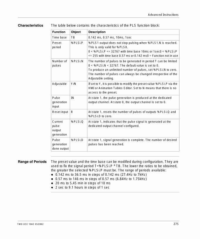
Advanced Instructions
Characteristics The table below contains the characteristics of the PLS function block:
Range of Periods The preset value and the time base can be modified during configuration. They are used to fix the signal period T=%PLSi.P * TB. The lower the ratios to be obtained, the greater the selected %PLSi.P must be. The range of periods available:l 0.142 ms to 36.5 ms in steps of 0.142 ms (27.4Hz to 7kHz)l 0.57 ms to 146 ms in steps of 0.57 ms (6.84Hz to 1.75kHz)l 20 ms to 5.45 min in steps of 10 msl 2 sec to 9.1 hours in steps of 1 sec
Function Object Description
Time base TB 0.142 ms, 0.57 ms, 10ms, 1sec
Preset period
%PLSi.P %PLS1 output does not stop pulsing when %PLS1.N is reached. This is only valid for %PLS0.0 < %PLSi.P <= 32767 with time base 10ms or 1sec0 < %PLSi.P <= 255 with time base 0.57 ms or 0.142 ms0 = Function not in use
Number of pulses
%PLSi.N The number of pulses to be generated in period T can be limited 0 < %PLSi.N < 32767. The default value is set to 0.To produce an unlimited number of pulses, set %PLSi.N to zero. The number of pulses can always be changed irrespective of the Adjustable setting.
Adjustable Y/N If set to Y, it is possible to modify the preset value %PLSi.P via the HMI or Animation Tables Editor. Set to N means that there is no access to the preset.
Pulse generation input
IN At state 1, the pulse generation is produced at the dedicated output channel. At state 0, the output channel is set to 0.
Reset input R At state 1, resets the number of pulses of outputs %PLSi.Q and %PLSi.D to zero.
Current pulse output generation
%PLSi.Q At state 1, indicates that the pulse signal is generated at the dedicated output channel configured.
Pulse generation done output
%PLSi.D At state 1, signal generation is complete. The number of desired pulses has been reached.
TWD USE 10AE 05/2002 275

Advanced Instructions
Operation The following is an illustration of the pulse diagram of the %PLS function block.
Special Cases
Input IN
Number of
Dedicated Output
%PLSi.Q
%PLSi.D
Special case Description
Effect of cold restart (%S0=1) Sets the %PLSi.P to that defined during configuration
Effect of warm restart (%S1=1)
Has no effect
Effect of a controller stop The output %Q0.0.0 or %Q0.0.1 is set to 0 regardless of the state of system bit %S8.
Effect of modifying the preset (%PLSi.P)
Takes effect immediately
Using 0.142ms or 0.57ms Time base
Forcing output %Q0.0.0 or %Q0.0.1 using a programming device does not stop the signal generation.
276 TWD USE 10AE 05/2002

Advanced Instructions
Drum Controller Function Block (%DR)
Introduction The drum controller operates on a principle similar to an electromechanical drum controller which changes step according to external events. On each step, the high point of a cam gives a command which is executed by the control system. In the case of a drum controller, these high points are symbolized by state 1 for each step and are assigned to output bits %Qi.j or internal bits %Mi, known as control bits.
Illustration The following is an illustration of the drum controller function block.
%DRi
STEPS 8
Drum controller function block
R F
U
TWD USE 10AE 05/2002 277

Advanced Instructions
Parameters The drum controller function block has the following parameters:
Parameter Label Value
Number %DRi 0 to 3 Compact Controller0 to 7 Modular Controllers
Current step number %DRi.S 0-%DRi.S-7. Word which can be read and written. Written value must be a decimal immediate value. When written, the effect takes place on the next execution of the function block.
Number of steps 1 to 8 (default)
Return to step 0 input (or instruction)
R (Reset) At state 1, sets the drum controller to step 0.
Advance input (or instruction)
U (Up) On a rising edge, causes the drum controller to advance by one step and updates the control bits.
Output F (Full) Indicates that the current step equals the last step defined. The associated bit %DRi.F can be tested (for example, %DRi.F=1, if %DRi.S= number of steps configured - 1).
Control bits Outputs or internal bits associated with the step (16 control bits) and defined in the Configuration Editor.
278 TWD USE 10AE 05/2002

Advanced Instructions
Drum Controller Function Block Operation
Introduction The drum controller consists of the following:l A matrix of constant data (the cams) organized in eight steps (0 to 7) and 16 data
bits (state of the step) arranged in columns numbered 0 to F.l A list of control bits (one per column) corresponding either to outputs %Q0.i or
%Q1.i, or to internal bits %Mi. During the current step, the control bits take on the binary states defined for this step.
The example in the following table summarizes the main characteristics of the drum controller.
Operation In the above example, step 5 is the current step, control bits %Q0.1, %Q0.3, and %Q1.5 are set to state 1; control bits %Q0.6, %Q0.5, and %Q1.0 are set to state 0. The current step number is incremented on each rising edge at input U (or on activation of instruction U). The current step can be modified by the program.
Timing Diagram The following diagram shows the timing of the drum controller operation.
Column 0 1 2 D E F
Control Bits %Q0.1 %Q0.3 %Q1.5 %Q0.6 %Q0.5 %Q1.0
Step 0 0 0 1 1 1 0
Step 1 1 0 1 1 0 0
Step 5 1 1 1 0 0 0
Step 6 0 1 1 0 1 0
Step 7 1 1 1 1 0 0
20L-1 1
Input
Input
Step No.
Output
U:
R:
%DRi.S
%DRi.F
010 2 13
TWD USE 10AE 05/2002 279

Advanced Instructions
Special Cases The following table contains a list of special cases for drum controller operation.
Special Case Description
Effects of a cold restart (%S0=1)
Resets the drum controller to step 0 (updating the control bits).
Effect of a warm restart (%S1=1)
Updates the control bits after the current step.
Effect of a program jump If the drum controller is not scanned, the control bits are not reset to 0.
Updating the control bits Only occurs when there is a change of step or in the case of a warm or cold restart.
280 TWD USE 10AE 05/2002

Advanced Instructions
Programming and Configuring Drum Controllers
Introduction The following is an example of programming and configuring a drum controller. the first six outputs %Q0.0 to %Q0.5 are activated in succession each time input %I0.1 is set to 1. Input I0.0 resets the outputs to 0.
Programming Example
The following illustration is a drum controller function block with examples of reversible and non-reversible programming.
BLK %DR1LD %I0.0RLD %I0.1UOUT_BLKLD FST %Q0.8END_BLK
Non-Reversible program
LD %I0.0R %DR1LD %I0.1U %DR1LD %DR1.FST %Q0.8
Reversible program
Ladder diagram
R F
U
%DR1
STEPS 6
%I0.0
%I0.1
%Q0.8
TWD USE 10AE 05/2002 281

Advanced Instructions
Configuration The following information is defined during configuration:l The number of steps: 6l The output states (control bits) for each drum controller step.
l Assignment of the control bits.
1 2 3 4 5 6 7 8 9 10 11 12 13 14 15
Step 1 : 0 0 0 0 0 0 0 0 0 0 0 0 0 0 0
Step 2 : 1 0 0 0 0 0 0 0 0 0 0 0 0 0 0
Step 3 : 0 1 0 0 0 0 0 0 0 0 0 0 0 0 0
Step 4 : 0 0 1 0 0 0 0 0 0 0 0 0 0 0 0
Step 5 : 0 0 0 1 0 0 0 0 0 0 0 0 0 0 0
Step 6 : 0 0 0 0 1 0 0 0 0 0 0 0 0 0 0
1 : %Q0.0 4 : %Q0.1
2 : %Q0.2 5 : %Q0.3
3 : %Q0.4 6 : %Q0.5
282 TWD USE 10AE 05/2002

Advanced Instructions
Fast Counter Function Block (%FC)
Introduction The Fast Counter function block (%FC) serves as either an up-counter or a down-counter. It can count the rising edge of digital inputs up to frequencies of 5kHz. Because the Fast Counters are managed by specific hardware interrupts, maintaining maximum frequency sampling rates may vary depending on your specific application and hardware configuration.Compact controllers can be configured to use a maximum of three fast counters, while Modular controllers can only use a maximum of two. The Fast Counter function blocks %FC0, %FC1, and %FC2 use dedicated inputs %I0.0.2, %I0.0.3, and %I0.0.4 respectively. These bits are not reserved for their exclusive use. Their allocation must be considered with the use of other function blocks for these dedicated resources.
Illustration The following is example of a Fast Counter function block.
IN D
R
%FC0
TYPEADJ%FC0.P
TWD USE 10AE 05/2002 283

Advanced Instructions
Parameters The following table lists parameters for the Fast Counter function block.
Special Note If configured to be adjustable, then the application can change the preset value %FCi.P and current value %FCi.V at any time. But, a new value is taken into account only if the input reset is active or at the rising edge of output %FCi.D. This allows for successive different counts without the loss of a single pulse.
Operation If configured to up-count, when a rising edge appears at the dedicated input, the current value is incriminated by one. When the value is equal to the preset value %FCi.P, the Done output bit %FCi.D is set to 1 and zero is loaded into the current value %FCi.V. If configured to down-count, when a rising edge appears at the dedicated input, the current value is decreased by one. When the value is zero, the Done output bit %FCi.D is set to 1 and the preset value is loaded into the current value %FCi.P.
Parameter Label Description
Direction TYPE Set at configuration, this can be set to either up-count or down-count.
Preset Value %FCi.P Initial value set between 1 and 65535.
Adjustable Y/N If set to Y, it is possible to modify the preset value %FCi.P and %FCi.V with the Operator Display or Animatio Tables Editor. If set to N, there is no access to the preset.
Current Value %FCi.V The current value counts increment or decrement according the up or down counting function selected. For up counting, the current value resets to zero and counts up to 65536. For down counting, the current value resets to the preset value %FCi.P, and counts down to zero.
Enable Input IN At state 1, the current value is updated according to the pulses applied to the physical input. At state 0, the current value is held at its last value.
Reset %FCi.R Used to initialize the block. At state 1, the current value is reset to 0 if configured as an up-counter, or set to %FCi.P if configured as a down-counter.The done bit %FCi.D is set back to its default value.
Done %FCi.D This bit is set to 1 when:%FCi.V reaches the %FCi.P configured as an up-counter%FCi.V reaches zero when configured as a down-counter.This read-only bit is reset only by the setting %FCi.R to 1.
284 TWD USE 10AE 05/2002

Advanced Instructions
Configuration and Programming
In this example, the application counts a number of items up to 5000 while %I1.1 is set to 1. The input for %FC0 is the dedicated input %I0.0.2. When the preset value is reached, %FC0.D is set on and remains there until %FC0.R is reset by the result of "ANDing" %I1.2 and %M0.
Special Cases The following table contains a list of special cases for programming the %FC function block:
%I1.1
I1.2 %M0
%Q0.0IN
R
D%FC0
TYPE UPADJY%FC0.P 5000
BLKLDINLDANDROUT_BLKLD DST %Q0.0END_BLK
%FC0%I1.1
%I1.2%MO
Special Case Description
Effect of cold restart (%S0=1) Resets all the %FC attributes with the values configured by the user or user application.
Effect of warm restart (%S1=1) Has no effect.
Effect of controller stop The %FC continues to count with the attribute settings in effect at the time the controller was stopped.
TWD USE 10AE 05/2002 285

Advanced Instructions
Very Fast Counter Function Block (%VFC)
Introduction The Very Fast Counter function block (%VFC) is configurable using TwidoSoft and performs any one of the following functions:l Up/Down Counterl Up/Down Two-Phase Counterl Single Up Counterl Single Down Counterl Frequency MeterThe %VFC provides counting of digital inputs up to frequencies of 20 kHz. The Compact controllers can configure one very fast counter, while the Modular controllers can configure up to two very fast counters.
286 TWD USE 10AE 05/2002

Advanced Instructions
Dedicated I/O Assignments
The Very Fast Counter function blocks use dedicated inputs and auxiliary inputs and outputs. These inputs and outputs are not reserved for their exclusive use. Their allocation must be considered with the use of other function blocks for these dedicated resources. The following table summarizes these assignments:
Main inputs Auxiliary inputs Reflex outputs
%VFC Selected Use First input (pulses) IA
Second Input (pulses or UP/DO) IB
Preset Input Ipres
Catch Input Ica
First Reflex Output
Second Reflex Output
UP/DOWN counter
%I0.0.1 (Pulses) %I0.0.0 (Indicates UP=1/DO=0)
%I0.0.2 Optional
%I0.0.3 Optional
%Q0.0.2 Optional
%Q0.0.3 Optional
UP/DOWN Two-Phase counter
%I0.0.1 (Pulses) %I0.0.0 (pulse phase B)
%I0.0.2 Optional
%I0.0.3 Optional
%Q0.0.2 Optional
%Q0.0.3 Optional
Single UP counter
%I0.0.1 (Pulses) Not Used %I0.0.2 Optional
%I0.0.3 Optional
%Q0.0.2 Optional
%Q0.0.3 Optional
Single DOWN counter
%I0.0.1 (Pulses) Not Used %I0.0.2 Optional
%I0.0.3 Optional
%Q0.0.2 Optional
%Q0.0.3 Optional
Frequency counter
%I0.0.1 (Pulses) Not Used Not Used Not Used Not Used Not Used
UP/DOWN counter
%I0.0.7 (Pulses) %I0.0.6 (Indicates UP=1/DO=0)
%I0.0.5 Optional
%I0.0.4 Optional
%Q0.0.4 Optional
%Q0.0.5 Optional
UP/DOWN Two-Phase counter
%I0.0.7 (Pulses) %I0.0.6 (pulses phase B)
%I0.0.5 Optional
%I0.0.4 Optional
%Q0.0.4 Optional
%Q0.0.5 Optional
Single UP counter
%I0.0.7 (Pulses) Not Used %I0.0.5 Optional
%I0.0.4 Optional
%Q0.0.4 Optional
%Q0.0.5 Optional
Single DOWN counter
%I0.0.7 (Pulses) Not Used %I0.0.5 Optional
%I0.0.4 Optional
%Q0.0.4 Optional
%Q0.0.5 Optional
Frequency meter
%I0.0.7 (Pulses) Not Used Not Used Not Used Not Used Not Used
Comments:
UP/DO = UP/DOWNOpt. Use = Optional use
When not used, the input or output remains a normal digital I/O available to be managed by theapplication in the main cycle.
If %I0.0.2 is used %FC0 is not available.If %I0.0.3 is used %FC2 is not available.If %I0.0.4 is used %FC3 is not available.
TWD USE 10AE 05/2002 287

Advanced Instructions
Illustration Here is a block representation of the Very Fast Counter:
IN F
S TH1
TH0
%VFC0
TYPET_OUT0T_OUT1ADJ%VFC0.P
U
288 TWD USE 10AE 05/2002

Advanced Instructions
Parameters The following table lists characteristics for the very fast counter function block.
Function Description Values VFC
Use4
Run-time Access
Current Value(%VFCi.V)
Current value that is increased or decreased according to the physical inputs and the function selected. This value can be set or reset using Set Input (%VFCi.S).
0 -> 65535 CM Read
Preset Value(%VFCi.P)
Only used by the up/down counting function and single up or down counting.
0 -> 65535 CM or FM
Read and
Write1
Capture Value
Only used by the up/down counting function and single up or down counting.
0 -> 65535 CM Read
Counting direction(%VFCi.U)
Set by the system, this bit is used by the up/down counting function to indicate to you the direction of counting. When set to 1, the counting is up and when set to 0 the counting is down.As a single phase up or down counter, %I0.0.0 decides the direction for %VFC0 and %I0.0.6 for %VFC1.For a two-phase up/down counter, it is the phase difference between the two signals that determines the direction. For %VFC0, %I0.0 is dedicated for IB and %I0.1 for IA. For %VFC1, %I0.6 is dedicated for IB and %I0.7 for IA.
0 (Down)1 (Up)
CM Read
Enable Reflex Output 0(%VFCi.R)
Enable Reflex Ouput 0 0 (Disable)1 (Enable)
CM Read and
Write2
Enable Reflex Output 1(%VFCi.S)
Enable Reflex Output 1 0 (Disable)1 (Enable)
CM Read and
Write2
Threshold Value S0(%VFCi.S0)
This word contains the value of threshold 0. The meaning is defined during configuration of the function block. Note that this value must be less than %VFCi.S1.
0 -> 65535 CM Read and
Write2
TWD USE 10AE 05/2002 289

Advanced Instructions
Threshold Value S1(%VFCi.S1)
This word contains the value of threshold 0. The meaning is defined during configuration of the function block. Note that this value must be greater than %VFCi.S0.
0 -> 65535 CM Read and
Write1
Frequency Measure Valid(%VFCi.M)
Bit used to determine if the controller has finished a frequency measurement.
0 (Invalid)1 (Valid)
FM Read and Write
Frequency Measure Time Base(%VFCi.T)
Configuration item for 100 or 1000 millisecond time base.
1000 or 100
FM Read and
Write1
Adjustable(Y/N)
Configurable item that when selected, allows the user to modify the preset, threshold, and frequency measure time base values while running.
0 (No) 1 (Yes)
CM or FM
No
Enable Input(IN)
Used to validate or inhibit the current function.
0 (No) CM or FM
Read and
Write3
Set Input(S)
Depending on the configuration, at state 1:l Up/Down or Down Counting: Set the
current value to the preset valuel Single Up Counting: Resets the current
value to zeroIn addition, this also initializes the operation of the threshold outputs and takes into account any user modifications to the threshold values set by the Operator Display or user program.
0 or 1 CM or FM
Read and Write
Overflow Output(F)
Set to 1 if %VFCi.V passes from 0 to 65535 or 0 to 65535. This value is cleared by a setting the preset value using a digital input or the S instruction or a cold restart.
0 or 1 CM Read
Function Description Values VFC
Use4
Run-time Access
290 TWD USE 10AE 05/2002

Advanced Instructions
ThresholdBit 0(%VFCi.TH0)
Set to 1 when the current value is greater than or equal to the threshold value %VFCi.S0. It is advisable to test this bit only once in the program because it is updated in real time. The user application is responsible for the validity of the value at its time of use.
0 or 1 CM Read
ThresholdBit 1(%VFCi.TH1)
Set to 1 when the current value is greater than or equal to the threshold value %VFCi.S1. It is advisable to test this bit only once in the program because it is updated in real time. The user application is responsible for the validity of the value at its time of use.
0 or 1 CM Read
Note: 1. Writable only if Adjust is set to one.2. Access available only if configured.3. Read and write access only through the application, not the Operator Display or
Animation Tables Editor.4. CM = Counting Mode and FM = Frequency Meter Mode.
Function Description Values VFC
Use4
Run-time Access
TWD USE 10AE 05/2002 291

Advanced Instructions
Counting Function Description
The very fast counting function works at a maximum frequency of 20 kHz, with a range of 0 to 65535. The pulses to be counted are applied in the following way:
Notes on Function Blocks
Increase or decrease operations are made on the rising edge of pulses, and only if the counting function is enabled.There are two optional inputs used in counting mode: ICa and IPres. ICa is used to capture the current value (%VFCi.V) and stored it in %VFCi.C. The Ica inputs are specified as %I0.0.3 for %VFC0 and %I0.0.4 for %VFC1 if available.When IPres input is active, the current value is effected in the following ways:l For up counting, %VFCi.V is reset to 0l For down-counting, %VFCi.V is set to %VFCi.Pl For frequency counting, %VFCi.V and VFCi.M are set to 0Also note that %VFCi.F will be reset to zero. The IPres inputs are specified as %I0.0.2 for %VFC0 and %I0.0.5 for %VFC1 if available.
Notes on Function Block Outputs
For all functions, the current value is compared to two thresholds (%VFCi.S0 and % VFCi.S1). According to the result of this comparison two bit objects (%VFCi.TH0 and %VFCi.TH1) are set to 1 if the current value is greater or equal to the corresponding threshold, or reset to 0 in the opposite case. Reflex outputs (if configured) are set in accordance with these comparisons. Note that none, 1 or 2 outputs can be configured.%VFC.U is an output of the FB, it gives the direction of the associated counter variation (1 for UP, 0 for DOWN).
Function Description %VFC0IA ... IB
IA ... IBIA ... IB
UP/Down Counter The pulses are applied to the physical input, the current operation (increase/decrease) is given by the state of the physical input IB.
%I0.0.1 %I0.0.0 %I0.0.7 %I0.0.6
UP/Down 2-Phase Counter
The two phases of the encoder are applied to physical inputs IA and IB.
%I0.0.1 %I0.0.0 %I0.0.7 %I0.0.6
Single Up Counter The pulses are applied to the physical input IA. (IB is not used).
%I0.0.1 NA %I0.0.7 NA
Single Down Counter
The pulses are applied to the physical input IA. (IB is not used)
%I0.0.1 NA %I0.0.7 NA
292 TWD USE 10AE 05/2002

Advanced Instructions
Counting Function Diagram
&
&
>1
>1
VFC Counter
Current Value
Comparison
%VFCi.U
Direction ofCounting
%VFCi.FOverflowOutput
%VFCi.V
CurrentValue
%VFCi.TH0
%VFCi.TH1
VFCiCCaptureValue
%Q0.0.xReflexOutput 0
%Q0.0.yReflexOutput 1
&
&
+
-
IA = up counter input(Single signal or phase 1)
IN %VFCi
%VFCi.P
IB = (UP/DOWN flag or phase 2)
S %VFCi
%VFCi.S0ThresholdValue 0
%VFCi.S1ThresholdValue 1
%VFCi.R or%VFCi.S Enable
IPres = (Preset Input)
%ICa = Catch Input
Read %VFCi.VInstruction
Current Value
TWD USE 10AE 05/2002 293

Advanced Instructions
Single Up Counter Operation
The following is an example of using %VFC in a single up counter mode. The following configuration elements have been set for this example:%VFC0.P preset value is 17%VFC0.S0, lower threshold value is 14, and %VFC0.S1 upper threshold is 20.
A timing chart follows:
Reflex Output
<%VFC.S0 %VFC0.S0 <= < %VFC0.S1 >= %VFC0.S1
%Q0.0.2 X
%Q0.0.3 X X
%VFC0.P = 17%VFC0.S0 = 14%VFC0.S1 = 20
IN
S
65535
20
17
14
0%VFC0.V
F
TH0
Reflexoutput 0
TH1
Reflexoutput 1
1 2 3 4
: %VFC0.U = 1 because VFC is an up-counter
: change %VFC0.S1 to 17
: S input active makes threshold S1 new value to be granted in next count
: a catch of the current value is made, so %VFC0.C = 17
1
2
3
4
294 TWD USE 10AE 05/2002

Advanced Instructions
Single Down Counter Operation
The following is an example of using %VFC in a single down counter mode. The following configuration elements have been set for this example:%VFC0.P preset value is 17%VFC0.S0, lower threshold value is 14 %VFC0.S1, upper threshold is 20.
Reflex Output
<%VFC.S0 %VFC0.S0 <= < %VFC0.S1 >= %VFC0.S1
%Q0.0.2 X
%Q0.0.3 X X
TWD USE 10AE 05/2002 295

Advanced Instructions
%VFC0.P = 17%VFC0.S0 = 14%VFC0.S1 = 20
IN
S
65535
20
17
14
0%VFC0.V
F
TH0
Reflexoutput 0
TH1
Reflexoutput 1
1 3 4 5
: %VFC0.U = 1 because VFC is a down-counter
: change %VFC0.S1 to 17
: S input active makes threshold S1 new value to be granted in next count
1
2
3
4
2
5 : a catch of the current value is made, so %VFC0.C = 17
: change %VFC0.P to 20
296 TWD USE 10AE 05/2002

Advanced Instructions
Up-Down Counter Operation
The following is an example of using %VFC in an up-down counter mode. The following configuration elements have been set for this example:%VFC0.P preset value is 17%VFC0.S0, lower threshold value is 14 %VFC0.S1, upper threshold is 20.
Reflex Output <%VFC.S0 %VFC0.S0 <=< %VFC0.S1 %VFC0.S1
%Q0.0.2 X
%Q0.0.3 X X
TWD USE 10AE 05/2002 297

Advanced Instructions
%VFC0.P = 17%VFC0.S0 = 14%VFC0.S1 = 20
IN
S
65535
20
17
14
0%VFC0.V
F
TH0
Reflexoutput 0
TH1
Reflexoutput 1
1 3 4 5
: %VFC0.U = 1 because VFC is a down-counter
: change %VFC0.S1 to 17
: S input active makes threshold S1 new value to be granted in next count
1
2
3
4
2
5 : a catch of the current value is made, so %VFC0.C = 17
: change %VFC0.P to 20
U
298 TWD USE 10AE 05/2002

Advanced Instructions
Frequency Meter Function Description
The frequency meter function of a %VFC is used to measure the frequency of a periodic signal in Hz on input IA . The frequency range which can be measured is from 10Hz to 20kHz. The user can choose between 2 time bases, the choice being made by a new object %VFC.T (Time base). A value of 100 = time base of 100 ms and a value of 1000 = time base of 1 second.
The object %VFC.M (Frequency Measure Valid) is set to 1 to indicate that the measurement is complete.
Time Base Measurement range Precision Update
100 ms 100 Hz to 20 Khz 0.05% for 20kHz 10% for 100Hz
10 times per second
1 s 10 Hz to 20 Khz 0.005% for 20kHz 10% for 10Hz
Once per second
TWD USE 10AE 05/2002 299

Advanced Instructions
Frequency Meter Function Diagram
The following is a frequency meter function diagram:
& VFC Counter
Current Value
%VFCi.FOverflowOutput
%VFCi.V
Frequency
+
IN %VFCi
S %VFCi
Current Valuemeasured
%VFCi.M
(Update flag)
1000 ms 100 ms
Set currentvalue to 0
%VFCi.T
Select timebase
IA
Signal to be measured
300 TWD USE 10AE 05/2002

Advanced Instructions
Frequency Meter Operation
The following is a timing diagram example of using %VFC in a frequency meter mode.
Special Cases The following table contains a list of special cases for programming the %VFC function block:
IN
S
Time-base
%VFC0.V
%VFC0.M
1 2 3 4 5
f1 f2 0 f3 f4 f5f30
1
2
: The first frequency measurement starts here.
: The current frequency value is updated.
: S input active sets %VFC0.V to 0.
: Change %VFC0.T to 100 ms: this change cancels the current measurement and starts another one.
: %VFC0.M is set to 0 by the user.
3
4
5
Special case Description
Effect of cold restart (%S0=1) Resets all the %VFC attributes with the values configured by the user or user application.
Effect of warm restart (%S1=1) Has no effect
Effect of Controller stop The %VFC stops its function and the outputs stay in their current state.
TWD USE 10AE 05/2002 301

Advanced Instructions
Transmitting/Receiving Messages - the Exchange Instruction (EXCH)
Introduction A Twido controller can be configured to communicate with Modbus slave devices or can send and/or receive messages in character mode (ASCII). TwidoSoft provides the following functions for these communications:l EXCH instruction to transmit/receive messagesl Exchange control function block (%MSG) to control the data exchangesThe Twido controller uses the protocol configured for the specified port when processing an EXCH instruction. Each communications port can be configured for different protocols or the same, and the EXCH instruction or %MSG function block for each communications port is accessed by appending the port number (1 or 2).
EXCH Instruction The EXCH instruction allows a Twido controller to send and/or receive information to/from ASCII devices. The user defines a table of words (%MWi:L or %KWi:L) containing the data to be sent and/or received (up to 64 data words in transmission and/or reception). The format for the word table is described in the paragraphs about each protocol. A message exchange is performed using the EXCH instruction.
Syntax The following is the format for the EXCH instruction: [EXCHx %MWi:L] or [EXCHx %KWi:LWhere: x = port number (1 or 2); L = Number of words in the word table. Values of the internal word table %MWi:L are such as i+L - 255.]The Twido controller must finish the exchange from the first EXCHx instruction before a second exchange instruction can be started. The %MSG function block must be used when sending several messages.
302 TWD USE 10AE 05/2002

Advanced Instructions
Exchange Control Function Block (%MSG)
Introduction The %MSG function block manages data exchanges and has three functions:l Communications error checking
Error checking verifies that the block length (word table) programmed with the EXCH instruction is large enough to contain the length of the message to be sent (compare with length programmed in the least significant byte of the first word of the word table).
l Coordination of multiple messagesTo ensure coordination when sending multiple messages, the %MSG function block provides the information required to determine when a previous message is complete.
l Transmission of priority messages The %MSG function block allows current message transmissions to be stopped in order to allow the immediate sending of an urgent message.
The programming of the %MSG function block is optional.
Illustration The following is an example of the %MSG function block.
R%MSG
D
E
TWD USE 10AE 05/2002 303

Advanced Instructions
Parameters The following table lists parameters for the %MSG function block.
If an error occurs when using an EXCH instruction, bits %MSG.D and %MSG.E are set to 1, and system word %SW63 contains the error code for Port 1, and %SW64 contains the error code for Port 2. See System Words (%SW), p. 325.
Reset Input (R) When the Reset input is set to 1:l Any messages that are being transmitted are stopped.l The Fault (Error) output is reset to 0.l The Done bit is set to 1.A new message can now be sent.
Fault (Error) Output (%MSG.E)
The error output is set to 1 either because of a communications programming error or a message transmission error. The error output is set to 1 if the number of bytes defined in the data block associated with the EXCH instruction (word 1, least significant byte) is greater than 128 (80 in hexadecimal). The error output is also set to 1if a problem exists in sending a Modbus message to a Modbus device. In this case, the user should check wiring, and that the destination device supports Modbus communication.
Communications Done output (%MSG.D)
When the Done output is set to 1, the Twido controller is ready to send another message. Use of the %MSG.D bit is recommended when multiple messages are sent. If it is not used, messages may be lost.
Parameter Label Value
Reset input (or instruction)
R At state 1, reinitializes communication: %MSG.E = 0, and %MSG.D = 1.
Comm. done output
%MSG.D State 1, comm. done, if:l End of transmission (if transmission)l End of reception (end character received)l Errorl Reset the blockState 0, request in progress.
Fault (Error) output
%MSG.E State 1, comm. done, if:l Bad commandl Table incorrectly configuredl Incorrect character received (speed, parity, etc.)l Reception table full (not updated)State 0, message length OK, link OK.
304 TWD USE 10AE 05/2002
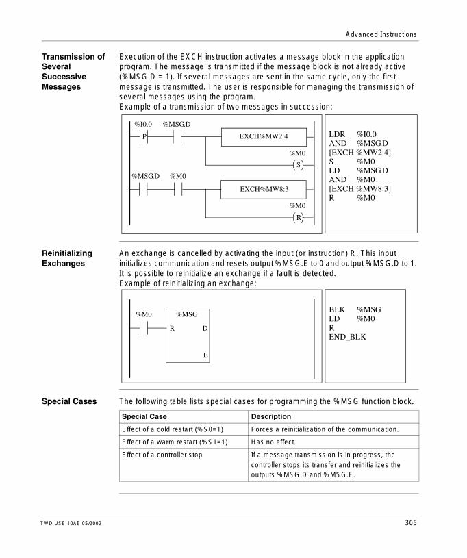
Advanced Instructions
Transmission of Several Successive Messages
Execution of the EXCH instruction activates a message block in the application program. The message is transmitted if the message block is not already active (%MSG.D = 1). If several messages are sent in the same cycle, only the first message is transmitted. The user is responsible for managing the transmission of several messages using the program.Example of a transmission of two messages in succession:
Reinitializing Exchanges
An exchange is cancelled by activating the input (or instruction) R. This input initializes communication and resets output %MSG.E to 0 and output %MSG.D to 1. It is possible to reinitialize an exchange if a fault is detected.Example of reinitializing an exchange:
Special Cases The following table lists special cases for programming the %MSG function block.
LDR %I0.0AND %MSG.D[EXCH %MW2:4]S %M0LD %MSG.DAND %M0[EXCH %MW8:3]R %M0
%I0.0 %MSG.D
P EXCH%MW2:4
%M0
S
EXCH%MW8:3
%M0
R
%MSG.D %M0
BLK %MSGLD %M0R END_BLK
%M0 %MSG
R D
E
Special Case Description
Effect of a cold restart (%S0=1) Forces a reinitialization of the communication.
Effect of a warm restart (%S1=1) Has no effect.
Effect of a controller stop If a message transmission is in progress, the controller stops its transfer and reinitializes the outputs %MSG.D and %MSG.E.
TWD USE 10AE 05/2002 305

Advanced Instructions
13.2 Clock Functions
At a Glance
Overview This section describes the time management functions for Twido controllers.
What’s in this Section?
This section contains the following topics:
Topic Page
Clock Functions 307
Schedule Blocks 308
Time/Date Stamping 311
Setting the Date and Time 313
306 TWD USE 10AE 05/2002

Advanced Instructions
Clock Functions
Introduction Twido controllers have a time-of-day clock function, which requires the Real-Time Clock option (RTC) and provides the following:l Schedule blocks are used to control actions at predefined or calculated times.l Time/date stamping is used to assign time and dates to events and measure
event duration.The Twido time-of-day clock can be accessed by selecting Schedule Blocks from from the TwidoSoft Software menu. Additionally, the time-of-day clock can be set by a program. Clock settings continue to operate for up to 30 days when the controller is switched off, if the battery has been charged for at least six consecutive hours before the controller is switched off.The time-of-day clock has a 24-hour format and takes leap years into account.
RTC Correction Value
The RTC Correction value is necessary for the correct operation of the RTC. Each RTC unit has its own correction value written on the unit. This value is configurable in TwidoSoft by using the Configure RTC option from the Controller Operations dialog box.
TWD USE 10AE 05/2002 307

Advanced Instructions
Schedule Blocks
Introduction Schedule Blocks are used to control actions at a predefined month, day, and time. A maximum of 16 schedule blocks can be used and do not require any program entry.
Parameters The following table lists parameters for a schedule block:
Note: Check system bit %S51 to confirm that the Real-Time Clock (RTC) option is installed see System Bits (%S), p. 318. The RTC option is required for using schedule blocks.
Parameter Format Function/Range
Schedule block number
n n = 0 to 15
Configured Check box Check this box to configure the selected schedule block number.
Output bit %Qx.y.z Output assignment is activated by schedule block: %Mi or %Qj.k.This output is set to 1 when the current date and time are between the setting of the start of the active period and the setting of the end of the active period.
Start month January to December
The month to start the schedule block.
End month January to December
The month to end the schedule block.
Start date 1 - 31 The day in the month to start the schedule block.
End date 1 - 31 The day in the month to end the schedule block.
Start time hh:mm The time-of-day, hours (0 to 23) and minutes (0 to 59), to start the schedule block.
Stop time hh:mm The time-of-day, hours (0 to 23) and minutes (0 to 59), to end the schedule block.
Day of week Monday - Sunday
Check boxes that identify the day of the week for activation of the schedule block.
308 TWD USE 10AE 05/2002

Advanced Instructions
Enabling Schedule Blocks
The bits of system word %SW114 enable (bit set to 1) or disable (bit set to 0) the operation of each of the 16 schedule blocks.Assignment of schedule blocks in %SW114:
By default (or after a cold restart) all bits of this system word are set to 1. Use of these bits by the program is optional.
Output of Schedule Blocks
If the same output (%Mi or %Qj.k) is assigned by several blocks, it is the OR of the results of each of the blocks which is finally assigned to this object (it is possible to have several "operating ranges" for the same output).
%SW114
Scheduleblock #15
Scheduleblock #0
TWD USE 10AE 05/2002 309

Advanced Instructions
Example The following table shows the parameters for a summer month spray program example:
Using the following program, the schedule block can be disabled through a switch or a humidity detector wired to input %I0.1.
The following timing diagram shows the activation of output %Q0.2.
Time Dating by Program
Date and time are both available in system words %SW50 to %SW53 (see System Words (%SW), p. 325). It is therefore possible to perform time and date stamping in the controller program by making arithmetic comparisons between the current date and time and the immediate values or words %MWi (or %KWi), which can contain setpoints.
Parameter Value Description
Schedule block 6 Schedule block number 6
Output bit %Qx.y.z Activate output %Qx.y.z
Start month June Start activity in June
End month September Stop activity in September
Start date 21 Start activity on the 21st day of June
End date 21 Stop activity on the 21st day of September
Day of week Monday, Wednesday, Friday
Run activity on Monday, Wednesday and Friday
Start time 21:00 Start activity at 21:00
Stop time 22:00 Stop activity at 22:00
LD %I0.1ST %SW114:X6
%I0.1 %SW114:X6
%I0.1
%Q0.2
21 June
M W FM W FM W F
310 TWD USE 10AE 05/2002

Advanced Instructions
Time/Date Stamping
Introduction System words %SW50 to %SW53 contain the current date and time in BCD format (see Review of BCD Code, p. 246, which is useful for display on or transmission to a peripheral device. These system words can be used to store the time and date of an event (see System Words (%SW), p. 325.
Dating an Event To date an event it is sufficient to use assignment operations, to transfer the contents of system words to internal words, and then process these internal words (for example, transmission to display unit by EXCH instruction).
Programming Example
The following example shows how to date a rising edge on input %I0.1.
Once an event is detected, the word table contains:
Note: Date and time and also be set by using the optional Operator Display (see Time of Day Clock, p. 134).
Coding Most significant byte Least significant byte
%MW12 Second Day of the week (1)
%MW13 Hour Minute
%MW14 Month Day
%MW15 Century Year
Note: (1) 0 = Monday, 1 = Tuesday, 2 = Wednesday, 3 = Thursday, 4 = Friday, 5 = Saturday, 6 = Sunday.
LDR %I0.0[%MW12:4 := %SW50:4]
P %MW12:4 := %SW50:4
%I0.1
TWD USE 10AE 05/2002 311

Advanced Instructions
Example of Word Table
Example data for 13:40:30 on Monday, 19 April, 2002:
Date and Time of Last Stop
System words %SW54 to %SW57 contain the date and time of the last stop, and word %SW58 contains the code showing the cause of the last stop, in BCD format (see System Words (%SW), p. 325).
Word Value (hex) Meaning
%MW12 3000 30 seconds, 00 = Monday
%MW13 1340 13 hours, 40 minutes
%MW14 0419 04 = April, 19th
%MW15 2002 2002
312 TWD USE 10AE 05/2002

Advanced Instructions
Setting the Date and Time
Introduction You can update the date and time settings by using one of the following methods: l TwidoSoft
Use the Set Time dialog box. This dialog is available from the Controller Operations dialog box which is displayed by selecting Controller Operations from the Controller menu (see the TwidoSoft Operation Guide).
l System wordsUse system words %SW50 to %SW53 or system word %SW59.
The date and time settings can only be updated when the RTC option cartridge (TWDXCPRTC) is installed on the controller.
Using %SW 50 to %SW53
To use system words %SW50 to %SW53 to set the date and time, bit %S50 must be set to 1, which results in the following:l Cancels the update of words %SW50 to %SW53 via the internal clock.l Transmits the values written in words %SW50 to %SW53 to the internal clock.Programming example:
LD %S50R %S50
LDR %I0.1[%SW50 := %MW10][%SW51 := %MW11][%SW52 := %MW12][%SW53 := %MW13]S %S50
%S50
%I0.1
P %SW50 := %MW10
%SW51 := %MW11
%SW52 := %MW12
%SW53 := %MW13
%S50
S
R
%S50
TWD USE 10AE 05/2002 313

Advanced Instructions
Words %MW10 to %MW13 will contain the new date and time in BCD format (see Review of BCD Code, p. 246) and will correspond to the coding of words %SW50 to 53.The word table must contain the new date and time:
Example data for Monday, 19 April, 2002:
Using %SW59 Another method of updating the date and time is to use system bit %S59 and date adjustment system word %SW59.Setting bit %S59 to 1enables adjustment of the current date and time by word %SW59 (see System Words (%SW), p. 325). %SW59 increments or decrements each of the date and time components on a rising edge.
Coding Most significant byte Least significant byte
%MW10 Second Day of the week (1)
%MW11 Hour Minute
%MW12 Month Day
%MW13 Century Year
Note: (1) 0 = Monday, 1 = Tuesday, 2 = Wednesday, 3 = Thursday, 4 = Friday, 5 = Saturday, 6 = Sunday.
Word Value (hex) Meaning
%MW10 3000 30 seconds, 00 = Monday
%MW11 1340 13 hours, 40 minutes
%MW12 0419 04 = April, 19th
%MW13 2002 2002
314 TWD USE 10AE 05/2002

Advanced Instructions
Application Example
The following front panel is created to modify the hour, minutes, and seconds of the internal clock.
Description of the controls:l The Hours/Minutes/Seconds switch selects the time display to change using
inputs %I0.2, %I0.3, and %I0.4 respectively.l Push button "+" increments the selected time display using input %I0.0.l Push button "-" decrements the selected time display using input %I0.1.The following program reads the inputs from the panel and sets the internal clock.
Hours
Minutes
Seconds+ -
Hour Minute Second
13 40 30
LD %M0ST %S59LD %I0.2ANDR %I0.0ST %SW59:X3LD %I0.2ANDR %I0.1ST %SW59:X11LD %I0.3ANDR %I0.0ST %SW59:X2LD %I0.3ANDR %I0.1ST %SW59:X10LD %I0.4ANDR %I0.0ST %SW59:X1LD %I0.4ANDR %I0.1ST %SW59:X9
(Hour)
(Minute)
(Second)
%M0
%I0.2 %I0.0 %SW59:X3
P
%S59
%I0.4 %I0.1 %SW59:X9
P
%I0.4 %I0.0 %SW59:X1
P
%I0.3 %I0.1 %SW59:X10
P
%I0.2 %I0.1 %SW59:X11
P
%I0.3 %I0.0 %SW59:X2
P
TWD USE 10AE 05/2002 315

Advanced Instructions
316 TWD USE 10AE 05/2002

TWD USE 10AE 05/2002
14
System Bits and System WordsAt a Glance
Overview This chapter provides an overview of the system bits and system words that can be used to create control programs for Twido controllers.
What’s in this Chapter?
This chapter contains the following topics:
Topic Page
System Bits (%S) 318
System Words (%SW) 325
317
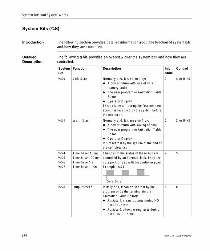
System Bits and System Words
System Bits (%S)
Introduction The following section provides detailed information about the function of system bits and how they are controlled.
Detailed Description
The following table provides an overview over the system bits and how they are controlled:
System Bit
Function Description Init State
Control
%S0 Cold Start Normally at 0. It is set to 1 by:l A power return with loss of data
(battery fault)l The user program or Animation Table
Editorl Operator DisplayThis bit is set to 1 during the first complete scan. It is reset to 0 by the system before the next scan.
0 S or U->S
%S1 Warm Start Normally at 0. It is reset to 1 by:l A power return with saving of datal The user program or Animation Table
Editorl Operator DisplayIt is reset to 0 by the system at the end of the complete scan.
0 S or U->S
%S4%S5%S6%S7
Time base: 10 msTime base 100 msTime base 1 sTime base 1 min
Changes in the status of these bits are controlled by an internal clock. They are not synchronized with the controller scan. Example: %S4
- S
%S8 Output freeze Initially at 1, it can be set to 0 by the program or by the terminal (in the Animation Table Editor):l At state 1, clears outputs during NO
CONFIG state.l At state 0, allows wiring tests during
NO CONFIG state.
1 U
5ms 5ms
318 TWD USE 10AE 05/2002

System Bits and Words
%S9 Reset outputs Normally not set. It can be set to 1 by the program or by the terminal (in the Animation Table Editor):l At state 1, outputs are forced to 0
when the controller is in RUN mode.l At state 0, outputs are updated
normally.
0 U
%S10 I/O fault Normally at 1. It is set to 0 by the system when a I/O fault is detected.
1 S
%S11 Watchdog overflow Normally at 0, it is set to 1 by the system when the program execution time (scan time) exceeds the maximum scan time (software watchdog). Watchdog overflow causes the controller to change to HALT.
0 S
%S12 Controller running This bit reflects the running state of the controller. The systems sets the bit to 1 when the controller is running, else 0 for stop, init, or any other state.
0 S
%S13 First scan Normally at 0, it is set to 1 by the system during the first scan after the controller has been changed to RUN.
1 S
%S17 Carry overflow Normally at 0, it is set to 1 by the system:l In the case of carry overflow during a
non-signed arithmetic operation (remainder)
l During a rotate or shift operation it indicates the output of a bit at 1. It must be tested by the user program after each operation where there is a risk of overflow, then reset to 0 by the user if an overflow occurs.
0 S->U
System Bit
Function Description Init State
Control
TWD USE 10AE 05/2002 319

System Bits and System Words
%S18 Arithmetic overflow or error
Normally at 0. It is set to 1 in the case of an overflow when a 16 bit operation is performed, that is:l A result greater than + 32767 or less
than - 32768l Division by 0l The square root of a negative numberl BTI or ITB conversion not significant:
BCD value out of limitsIt must be tested by the user program, after each operation where there is a risk of an overflow, then reset to 0 by the user if an overflow occurs.
0 S->U
%S19 Scan period overrun (periodic scan)
Normally at 0, this bit is set to 1 by the system in the event of a scan period overrun (scan time greater than the period defined by the user at configuration or programmed in %SW0).This bit is reset to 0 by the user.
0 S->U
%S20 Index overflow Normally at 0, it is set to 1 when the address of the indexed object becomes less than 0 or more than the maximum size of an object.It must be tested by the user program, after each operation where there is a risk of overflow, then reset to 0 if an overflow occurs.
0 S->U
%S21 GRAFCET initialization
Normally at 0. It is set to 1 by:l A cold restart, %S0=1l The user program, in the
preprocessing program part only, using a Set Instruction (S %S21) or a set coil -(S)- %S21.
l The terminal.At state 1, it causes GRAFCET initialization. Active steps are deactivated and initial steps are activated. It is reset to 0 by the system after GRAFCET initialization.
0 U->S
System Bit
Function Description Init State
Control
320 TWD USE 10AE 05/2002

System Bits and Words
%S22 GRAFCET RESET Normally at 0, it can only be set to 1 by the program in pre-processing.At state 1 it causes the active steps of the entire GRAFCET to be deactivated. It is reset to 0 by the system at the start of the execution of the sequential processing.
0 U->S
%S23 Preset and freeze GRAFCET
Normally at 0, it can only be set to 1 by the user program in the pre-processing program module.At state 1, it validates the presetting of the GRAFCET chart. Maintaining this bit at 1 freezes the GRAFCET (freezes the chart). It is reset to 0 by the system at the start of the execution of the sequential processing to ensure that the GRAFCET chart moves on from the frozen situation.
0 U->S
%S24 Operator Display Normally at 0, this bit can be set to 1 by the user.l At state 0, the Operator Display is
operating normally.l At state 1, the Operator Display is
frozen, stays on current display, blinking disabled, and input key processing stopped.
0 U->S
%S50 Updating the date and time using words %SW50 to 53
Normally at 0, this bit can be set to 1 or to 0 by the program or the Operator Display.l At state 0, the date and time can be
read.l At state 1, the date and time can be
updated.
0 U->S
System Bit
Function Description Init State
Control
TWD USE 10AE 05/2002 321

System Bits and System Words
%S51 Time-of-day clock status
Normally at 0, this bit can be set to 1 or to 0 by the program or the Operator Display.l At state 0, the date and time are set.l At state 1, the date and time must be
set by the user.When this bit is set to 1, the time of day clock data is not valid. The date and time may never have been configured, the battery may be low, or the controller correction constant may be invalid. State 1 transitioning to state 0 forces a write of the correction constant to the RTC.
0 U->S
%S59 Updating the date and time using word %SW59
Normally at 0, this bit can be set to 1 or to 0 by the program or the Operator Display.l At state 0, the date and time remain
unchanged.l At state 1, the date and time are
incremented or decremented according to the control bits set in %SW59.
0 U
%S69 User STAT LED display
At state 0, STAT LED is offAt state 1, STAT LED is on
0 U
%S70 Refreshing data on AS-i bus
This bit is set on 1 by the system at the end of each controller cycle or at the end of AS-i bus scanning cycle.On power-up, it indicates that all data has been refreshed at least once and it is thus significant.This bit is to be reset on 0 by the user.
0 S->U
%S73 Switching to protect mode on AS-i bus
Normally on 0, this bit is set on 1 by the user to switch to protected mode on the AS-i bus. Before this, the bit must have already been on 1. This bit will only be used in a wiring system test, and has no application within the controller.
0 S
System Bit
Function Description Init State
Control
322 TWD USE 10AE 05/2002

System Bits and Words
%S74 Saving configuration in AS-i bus
Normally on 0, this bit is set on 1 by the user to save the current configuration in the AS-i bus. This bit will only be used in a wiring system test, and has no application within the controller.
0 S
%S96 Backup program OK
This bit can be read at any time (either by the program or while adjusting), in particular after a cold start or a warm restart.l At state 0, the backup program is
invalid.l At state 1, the backup program is
valid.
0 S
%S97 Save %MW OK This bit can be read at any time (either by the program or while adjusting), in particular after a cold start or a warm restart.l At state 0, save %MW is not OK.l At state 1, save %MW is OK.
0 S
%S100 TwidoSoft communications cable connection
Shows whether the TwidoSoft communication cable is connected.l At state 1, TwidoSoft communications
cable is either not attached or TwidoSoft is connected.
l At state 0, TwidoSoft Remote Link cable is connected.
- S
%S110 Remote link exchanges
This bit is reset to 0 by the program or by the terminal.l At state 1 for a master, all remote link
exchanges (remote I/O only) are completed.
l At state 1 for a slave, exchange with master is completed.
0 S->U
System Bit
Function Description Init State
Control
TWD USE 10AE 05/2002 323

System Bits and System Words
Table Abbreviations Described
%S111 Single remote link exchange
l At state 0 for a master, a single remote link exchange is completed.
l At state 0 for a slave, single remote link exchange is detected.
l At state 1 for a master, single remote link exchange is active.
l At state 1 for a slave, single remote link exchange is detected.
0 S
%S112 Remote link connection
l At state 0 for a master, the remote link is disabled.
l At state 1 for a master, the remote link is enabled.
0 U
%S113 Remote link configuration/operation
l At state 0 for a master or slave, the remote link configuration/operation is OK.
l At state 1 for a master, the remote link configuration/operation has an error.
l At state 1 for a slave, the remote link configuration/operation has an error.
0 S->U
%S118 Remote I/O error Normally at 1, it is set to 0 when an I/O fault is detected on the remote link.
1 S
%S119 Local I/O error Normally at 1, it is set to 0 when an I/O fault is detected on the local I/O (base or expansion). %SW118 determines the nature of the fault. Resets to 1 when the fault disappears.
1 S
System Bit
Function Description Init State
Control
Abbreviation Description
S Controlled by the system
U Controlled by the user
U->S Set to 1 by the user, reset to 0 by the system
S->U Set to 1 by the system, reset to 0 by the user
324 TWD USE 10AE 05/2002

System Bits and Words
System Words (%SW)
Introduction The following section provides detailed information about the function of the system words and how they are controlled.
Detailed Description
The following table provides detailed information about the function of the system words and how they are controlled:
System Word
Function Description Control
%SW0 Controller scan period (periodic task)
Modifies controller scan period defined at configuration through the user program in the Animation Table Editor.
U
%SW6 Controller state
Controller state:0 = NO CONFIG2 = STOPPED3 = RUN4 = HALT
S
%SW7 Controller status
Bit [0] Backup/restore in progressBit [1] Controller configuration OKBit [3..2] EEPROM status bits:l 00 = No cartridgel 01 = 32 KB EEPROM cartridgel 10 = 64 KB EEPROM cartridgel 11 = Reserved for future useBit [4] Application in RAM different than EEPROM (1 = yes)Bit [5] Application in RAM different than cartridge (1 = yes)Bit [6] Some device tasks are in STOP modeBit [7] Controller reservedBit [8] Application in write protect modeBit [9] UnusedBit [10] Second serial port installedBit [11] Second serial port type (0 = EIA RS-232, 1 = EIA RS-485)Bit [12] Valid application in internal memory (1 = yes)Bit [13] Valid application in cartridge (1 = yes)Bit [14] Valid application in RAM (1 = yes)Bit [15] Ready to run
S
%SW11 Software watchdog time
Initializes to maximum watchdog time. The value (10 to 500 ms) is defined by the configuration.
U
TWD USE 10AE 05/2002 325

System Bits and System Words
%SW18-%SW19
100 ms absolute timer counter
100 ms absolute timer counter.%SW18 represents the least significant bytes and %SW19 represents the most significant bytes.
S and U
%SW30 Last scan time Shows execution time of the last controller scan cycle (in ms).Note: This time corresponds to the time elapsed between the start (acquisition of inputs) and the end (update of outputs) of a scan cycle.
S
%SW31 Max scan time Shows execution time of the longest controller scan cycle since the last cold start (in ms).Note: This time corresponds to the time elapsed between the start (acquisition of inputs) and the end (update of outputs) of a scan cycle.
S
%SW32 Min scan time Shows execution time of shortest controller scan cycle since the last cold start (in ms).Note: This time corresponds to the time elapsed between the start (acquisition of inputs) and the end (update of outputs) of a scan cycle.
S
System Word
Function Description Control
%SW49%SW50%SW51%SW52%SW53
Schedule block function
Schedule block (RTC) function: words containing current date and time values (in BCD):
S and U
%SW49 xN Day of the week (N=0 for Monday)
%SW50 00SS Seconds
%SW51 HHMM Hour and Minute
%SW52 MMDD Month and Day
%SW53 CCYY Century and Year
These words are controlled by the system when bit %S50 is at 0. These words can be written by the user program or by the terminal when bit %S50 is set to 1.
System Word
Function Description Control
326 TWD USE 10AE 05/2002

System Bits and Words
%SW54%SW55%SW56%SW57
Schedule block function
Schedule block (RTC) function.System words containing the date and time of the last power failure or controller stop (in BCD):
S
%SW54 SS Seconds
%SW55 HHMM Hour and minute
%SW56 MMDD Month and day
%SW57 CCYY Century and year
%SW58 Code of last stop
Displays code giving cause of last stop: S
1 = Run/Stop input edge
2 = Stop at software fault (controller scan overshoot)
3 = Stop command
4 = Power outage
5 = Stop at hardware fault
System Word
Function Description Control
%SW59 Adjust current date
Adjusts the current date.Contains two sets of 8 bits to adjust current date.The operation is always performed on rising edge of the bit. This word is enabled by bit %S59.
U
Increment Decrement Parameter
bit 0 bit 8 Day of the week
bit 1 bit 9 Seconds
bit 2 bit 10 Minutes
bit 3 bit 11 Hours
bit 4 bit 12 Days
bit 5 bit 13 Months
bit 6 bit 14 Years
bit 7 bit 15 Centuries
%SW60 RTC correction value
Real-Time Clock (RTC) correction value U
System Word
Function Description Control
TWD USE 10AE 05/2002 327

System Bits and System Words
%SW63 EXCH1 block error code
If an error occurs when using the EXCH block, output bits %MSG.D and %MSG.E change to 1. This system word contains the error code. The possible values are as follows:l 0: No error, exchange correctl 1: Transmission buffer too largel 2: Transmission buffer too smalll 3: Table too smalll 4: Receive table overflowl 5: Time - out elapsedl 6: Transmission errorl 7: Bad ASCII command (ASCII mode only)l 8: Selected port not configurable/availablel 9: Reception error (ASCII mode only)l 10: Table %KWi prohibitedl 11: Transmission offset larger than transmission
tablel 12: Reception offset larger than reception tablel 13: Controller stopped EXCH processingThis word is set to 0 every time the EXCH block is used.
S
%SW64 EXCH2 block error code
Same as %SW63 S
%SW67 Function and type of controller
Contains the following information:l Controller type bits [0 -11]l 8B0 = TWDLCAA10DRFl 8B1 = TWDLCAA16DRFl 8B2 = TWDLMDA20DUK/DTKl 8B3 = TWDLCAA24DRFl 8B4 = TWDLMDA40DUK/DTKl 8B6 = TWDLMDA20DRTl Bit 12 not used = 0l Remote link address bits [13-15]l 000 = master controllerl 001 - 111 = remote controller 1-7l 001 = address 1l 111 = address 7
S
System Word
Function Description Control
328 TWD USE 10AE 05/2002

System Bits and Words
System Word
Function Description Control
%SW76 to %SW79
Down counters 1-4
These 4 words serve as 1 ms timers. They are decremented individually by the system every ms if they have a positive value. This gives 4 down counters down counting in ms which is equal to an operating range of 1 ms to 32767 ms. Setting bit 15 to 1 can stop decrementing.
S and U
%SW96 Command and/or diagnostics for save/restore function of application program and %MW.
Bit [0] This bit is set by the User Logic to indicate that memory words, %MWi, need to be stored to EEPROM. The executive sets this bit back to 0 when the %MW store process has begun, not when it is finished.Bit [1] This bit is set by the firmware to indicate when the save is complete. This means that when the bit is 1, any save request to EEPROM has completed. This bit is set to zero upon the next save to EEPROM request.Bit [2] When set to 1, this indicates that an error has occurred during the last save or restore request. See bits 8, 9, 10, and 14 for additional information.Bit [6] Controller contains a valid application(1 = yes).Bit [8] Number of %MWs specified in %SW97 greater than the maximum number of memory words allowed by TwidoSoft (1 = yes).Bit [9] Number of %MWs specified in %SW97 is greater than the maximum number of memory words allowed by TwidoSoft (1 = yes)Bit [10] Difference between internal RAM and internal EEPROM (1 = yes).Bit [14] EEPROM write fault has occurred (1 = yes).
TWD USE 10AE 05/2002 329

System Bits and System Words
%SW97 Command or diagnostics for save/restore function
This value represents the physical number of memory words %MW to be saved to internal EEPROM only. It is not used in a restore of memory words.When this number is 0, memory words will not be stored. The user must set the user logic program, otherwise it will be set to 0 in the controller application except for in the following case:On cold start, this word is set on -1 if the internal Flash EEPROM has no saved memory word %MW file. In the case of a cold start where the internal Flash EEPROM contains a memory word %MW file, the value of the number of saved memory words in the file must be set in this system word %SW97.
U
System Word
Function Description Control
%SW111 Remote link status
Two bits for each remote controller(master only):x0-5:0 - remote controller 1-6 not present1- remote controller 1-6 presentx6:0 - remote controller 7 not present1 - remote controller 7 presentx8-13:0 - remote I/O detected at remote controller 1-61 - peer controller detected at remote controller 1-6x14:0 - remote I/O detected at remote controller 71 - peer controller detected at remote controller 7
S
%SW112 Remote link configuration/operation error code
0 - operations are successful1 - timeout detected (slave)2 - checksum error detected (slave)3 - configuration mismatch (slave)This is set by the system, and must be reset by the user.
S
System Word
Function Description Control
330 TWD USE 10AE 05/2002

System Bits and Words
%SW113 Remote link configuration
Two bits for each remote controller (master only):x0-5:0 - remote controller 1-6 not configured1 - remote controller 1-6 configuredx6:0 - remote controller 7 not configured1 - remote controller 7 configuredx8-13:0 - remote I/O configured as remote controller 1-61 - peer controller configured as remote controller 1-6x14:0 - remote I/O configured as remote controller 71 - peer controller configured as remote controller 7
S
%SW114 Enable schedule blocks (RTC)
Enables or disables operation of schedule blocks (RTC) by the user program or Operator Display.Bit 0: 1 = enables schedule block #0Bit 15: 1 = enables schedule block #15Initially all schedule blocks are enabled, initial state is 0. If no schedule blocks are configured then the default value is FFFF.
S and U
%SW118 Base controller status word
Shows faults detected on master controller.Bit 9: 0= external fault or comm. FaultBit 12: 0= RTC not installedBit 13: 0= configuration fault (I/O extension configured but absent or faulty).All the other bits of this word are set to 1 and are reserved. For a controller which has no fault, the value of this word is FFFFh.
S
%SW120 Expansion I/O module health
One bit per module.Address 0 = Bit 01 = Unhealthy0 = OK
S
System Word
Function Description Control
TWD USE 10AE 05/2002 331

System Bits and System Words
Table Abbreviations Described
Abbreviation Description
S Controlled by the system
U Controlled by the user
332 TWD USE 10AE 05/2002

Glossary
% Prefix that identifies internal memory addresses in the controller that are used to store the value of program variables, constants, I/O, and so on.
Addresses Internal registers in the controller used to store values for program variables, constants, I/O, and so on. Addresses are identified with a percentage symbol (%) prefix. For example, %I0.1 specifies an address within the controller RAM memory containing the value for input channel 1.
Analog Potentiometer
An applied voltage that can be adjusted and converter into a digital value for use by an application.
Analyze Program A command that compiles a program and checks for program errors: syntax and structure errors, symbols without corresponding addresses, resources used by the program that are not available, and if the program does not fit in available controller memory. Errors are displayed in the Program Errors Viewer.
Animation Table Table created within an language editor or an operating screen. When a PC is connected to the controller, provides a view of controller variables and allows values to be forced when debugging. Can be saved as a separate file with an extension of .tat.
!
A
TWD USE 10AE 05/2002 333

Glossary
Animation Tables Editor
A specialized window in the TwidoSoft application for viewing and creating Animation Tables.
Application A TwidoSoft application consists of a program, configuration data, symbols, and documentation.
Application Browser
A specialized window in the TwidoSoft that displays a graphical tree-like view of an application. Provides for convenient configuration and viewing of an application.
Application file Twido applications are stored as file type .twd.
ASCII American Standard Code for Information Interchange. A communication protocol that uses seven bits to represent alphanumeric characters including letters, numbers, and some graphical and control characters.
Auto Line Validate
When inserting or modifying List instructions, this optional setting allows for program lines to be validated as each is entered for errors and unresolved symbols. Each element must be corrected before you can exit the line. Selected using the Preferences dialog box.
Auto Load A feature that is always enabled and provides for the automatic transfer of an application from a backup cartridge to the controller RAM in case of a lost or corrupted application. At power up, the controller compares the application that is presently in the controller RAM to the application in the optional backup memory cartridge (if installed). If there is a difference, then the copy in the backup cartridge is copied to the controller and the internal EEPROM. If the backup cartridge is not installed, then the application in the internal EEPROM is copied to the controller.
Backup A command that copies the application in controller RAM into both the controller internal EEPROM and the optional backup memory cartridge (if installed).
Coil A ladder diagram element representing an output from the controller.
B
C
334 TWD USE 10AE 05/2002

Glossary
Cold Start or Restart
A start up by the controller with all data initialized to default values, and the program started from the beginning with all variables cleared. All software and hardware settings are initialized. A Cold Restart can be caused automatically by a power failure (Compact controllers only), or by loading a new application into controller RAM. All Compact controllers or any controller without battery backup always power up in Cold Start.
Comment Lines In List programs, comments can be entered on separate lines from instructions. Comments lines do not have line numbers, and must be inserted within parenthesis and asterisks such as: (*COMMENTS GO HERE*).
Comments Comments are text you enter to document the purpose of a program. For Ladder programs, enter up to three lines of text in the Rung Header to describe the purpose of the rung. Each line can consist of 1 to 64 characters. For List programs, enter text on n unnumbered program line. Comments must be inserted within parenthesis and asterisks such as: (*COMMENTS GO HERE*).
Compact Controller
Type of Twido controller that provides a simple, all-in-one configuration with limited expansion. Modular is the other type of Twido controller.
Configuration Editor
Specialized TwidoSoft window used to manage hardware and software configuration.
Constants A memory unit such as a bit or word whose contents cannot be modified by the program being executed.
Contact A ladder diagram element representing an input to the controller.
Controller Twido programmable controller. There are two types of controllers: Compact and Modular.
Counter A function block used to count events (up or down counting).
Cross References
Generation of a list of operands, symbols, line/rung numbers, and operators used in an application to simplify creating and managing applications.
Cross References Viewer
A specialized window in the TwidoSoft application for viewing cross references.
TWD USE 10AE 05/2002 335

Glossary
Data Variable See Variable.
Date/Clock Functions
Allow control of events by month, day of month, and time of day. See Schedule Blocks.
Drum Controller A function block that operates similar to an electromechanical drum controller with step changes associated with external events.
EEPROM Electrically Erasable Programmable Read-Only Memory. Twido has an internal EEPROM and an optional external EEPROM memory cartridge.
Erase This command deletes application storage and has two options: delete the contents of the controller RAM, the controller internal EEPROM, and an installed optional backup cartridge; or, only delete the content of an installed optional backup cartridge.
Executive Loader
A 32-Bit Windows application used for downloading a new Firmware Executive program to a Twido controller.
Expansion Bus Expansion I/O Modules connect to the base controller using this bus.
Expansion I/O Modules
Optional Expansion I/O Modules are available to add I/O points to a Twido controller. (Not all controller models allow expansion).
Fast Counters A function block that provides for faster up/down counting than available with the Counters function block. A Fast Counter can count up to a rate of 5 KHz.
FIFO First In, First Out. A function block used for queue operations.
D
E
F
336 TWD USE 10AE 05/2002

Glossary
Firmware Executive
The Firmware Executive is the operating system that executes your applications and manages controller operation.
Forcing Intentionally setting controller inputs and outputs to 0 or 1 values even if the actual values are different. Used for debugging while animating a program.
Function Block A program unit of inputs and variables organized to calculate values for outputs based on a defined function such as a timer or a counter.
Grafcet A program written in Grafcet language consists of steps containing a graphical and structured description of the operation of sequential automation. Simple graphic symbols are used to describe the sequence of steps.
Init A command that sets all data values to initial states. The controller must be in Stop or Error mode.
Initial State The operating state of TwidoSoft that is displayed on the Status Bar when TwidoSoft is started or does not have an open application.
Instance A unique object in a program that belongs to a specific type of function block. For example, in the timer format %TMi, i is a number representing the instance.
Instruction List Language
A program written in instruction list language (IL) is composed of a series of instructions executed sequentially by the controller. Each instruction is composed of a line number, an instruction code, and an operand.
Ladder Editor Specialized TwidoSoft window used to edit a Ladder program.
G
I
L
TWD USE 10AE 05/2002 337

Glossary
Ladder language A program written in Ladder language is composed of graphical representation of instructions of a controller program with symbols for contacts, coils, and blocks in a series of rungs executed sequentially by a controller.
Ladder List Rung Displays parts of a List program that are not reversible to Ladder language.
Latching input Incoming pulses are captured and recorded for later examination by the application.
LIFO Last In, First Out. A function block used for stack operations.
List Editor Simple program editor used to create and edit a List program.
Master Controller
A Twido controller configured to be the Master on a Remote Link network.
Memory Cartridge
Optional Backup Memory Cartridges that can be used to backup and restore an application (program and configuration data). Two sizes are available: 32K bytes and 64K bytes.
Memory Usage Indicator
A portion of the Status Bar in the TwidoSoft main window that displays a percentage of total controller memory used by an application. Provides a warning when memory is low.
Modbus A master-slave communications protocol that allows one single master to request responses from slaves.
Modular Controller
Type of Twido controller that offers flexible configuration with expansion capabilities. Compact is the other type of Twido controller.
Monitor State The operating state of TwidoSoft that is displayed on the Status Bar when a PC is connected to a controller in a non-write mode.
Offline Operation An operation mode of TwidoSoft when a PC is not connected to the controller and the application in PC memory is not the same as the application in controller memory. You create and develop an application in Offline operation.
M
O
338 TWD USE 10AE 05/2002

Glossary
Offline State The operating state of TwidoSoft that is displayed on the Status Bar when a PC is not connected to a controller.
Online Operation An operation mode of TwidoSoft when a PC is connected to the controller and the application in PC memory is the same as the application in controller memory. You debug and adjust an application in Online operation.
Online State The operating state of TwidoSoft that is displayed on the Status Bar when a PC is connected to the controller.
Operand A number, address, or symbol representing a value that a program can manipulate in an instruction.
Operating States Indicate the status of TwidoSoft and is displayed on the Status Bar. There are four operating states: Initial, Offline, Online, and Monitor.
Operator A symbol or code specifying the operation to be performed by an instruction.
PC Personal Computer.
Peer Controller A Twido controller configured as a slave on a Remote Link network. An application can be executed in the Peer Controller memory and the program can access both local and expansion I/O data, but I/O data can not be passed to the Master Controller. The program running in the Peer Controller passes information to the Master Controller by using network words (%INW and QNW).
PLS Pulse Generation. A function block that generates a square wave with a 50% on and 50% off duty cycle.
Preferences A dialog box with selectable options for setting up the List and Ladder program editors.
Program Errors Viewer
Specialized TwidoSoft window used to view program errors and warnings.
Programmable Controller
A Twido controller. There are two types of controllers: Compact and Modular.
P
TWD USE 10AE 05/2002 339

Glossary
Protection Refers to two different types of application protection: password protection which provides access control, and controller application protection which prevents unauthorized viewing and copying of an application.
PWM Pulse Width Modulation. A function block that generates a square wave with a variable duty cycle that can be set by a program.
RAM Random Access Memory. Twido applications are downloaded into internal volatile RAM to be executed.
Real-Time Clock An option that will keep the time even when the controller is not powered for a limited amount of time.
Reflex Output In a counting mode, the very fast counter’s current value (%VFC.V) is measured against its configured thresholds to determine the state of these dedicated outputs.
Registers Special registers internal to the controller dedicated to LIFO/FIFO function blocks.
Remote Controller
A Twido controller configured to communicate with a Master Controller on a Remote Link network.
Remote Link High-speed master/slave bus designed to communicate a small amount of data between a Master Controller and up to seven Remote Controllers (slaves). There are two types of Remote Controllers that can be configured to transfer data to a Master Controller: a Peer Controller that can transfer application data, or a Remote I/O Controller that can transfer I/O data. A Remote link network can consist of a mixture of both types.
Resource Manager
A component of TwidoSoft that monitors the memory requirements of an application during programming and configuring by tracking references to software objects made by an application. An object is considered to be referenced by the application if it is used as an operand in a list instruction or ladder rung. Displays status information about the percentage of total memory used, and provides a warning if memory is getting low. See Memory Usage Indicator.
Reversible Instructions
A method of programming that allows instructions to be viewed alternately as List instructions or Ladder rungs.
RTC See Real-Time Clock.
R
340 TWD USE 10AE 05/2002

Glossary
RTU Remote Terminal Unit. A protocol using eight bits that is used for communicating between a controller and a PC.
Run A command that causes the controller to run an application program.
Rung A rung is entered between two potential bars in a grid and is composed of a group of graphical elements joined to each other by horizontal or vertical links.The maximum dimensions of a rung are seven rows and eleven columns.
Rung Header A panel that appears directly over a Ladder rung and can be used to document the purpose of the rung.
Scan A controller scans a program and essentially performs three basic functions. First, it reads inputs and places these values in memory. Next, it executes the application program one instruction at a time and stores results in memory. Finally, it uses the results to update outputs.
Scan Mode Specifies how the controller scans a program. There are two types of scan modes: Normal (Cyclic), the controller scans continuously, or Periodic, the controller scans for a selected duration (range of 2 - 150 msec) before starting another scan.
Schedule Blocks A function block used to program Date and Time functions to control events. Requires Real-Time Clock option.
Step A Grafcet step designates a state of sequential operation of automation.
Stop A command that causes the controller to stop running an application program.
Symbol A symbol is a string of a maximum of 32 alphanumeric characters, of which the first character is alphabetic. It allows you to personalize a controller object to facilitate the maintainability of the application.
Symbol Table A table of the symbols used in an application. Displayed in the Symbol Editor.
S
TWD USE 10AE 05/2002 341

Glossary
Threshold Outputs
Coils that are controlled directly by the very fast counter (%VFC) according to the settings established during configuration.
Timer A function block used to select a time duration for controlling an event.
Twido A line of Schneider Electric controllers consisting of two types of controllers (Compact and Modular), Expansion Modules to add I/O points, and options such as Real-Time Clock, communications, operator display, and backup memory cartridges.
TwidoSoft A 32-Bit Windows, graphical development software for configuring and programming Twido controllers.
Unresolved Symbol
A symbol without a variable address.
Variable Memory unit that can be addressed and modified by a program.
Very Fast Counters
A function block that provides for faster counting than available with Counters and Fast Counters function blocks. A Very Fast Counter can count up to a rate of 20 KHz.
T
U
V
342 TWD USE 10AE 05/2002

Glossary
Warm Restart A power-up by the controller after a power loss without changing the application. Controller returns to the state which existed before the power loss and completes the scan which was in progress. All of the application data is preserved. This feature is only available on modular controllers.
W
TWD USE 10AE 05/2002 343

Glossary
344 TWD USE 10AE 05/2002

CBAIndex
Symbols%Ci, 218%DR, 277%FC, 283%INW, 33%MSG, 303%PLS, 274%QNW, 33%S, 318%S0, 318%S1, 318%S10, 319%S100, 323%S11, 319%S110, 323%S111, 324%S112, 324%S113, 324%S118, 324%S119, 324%S12, 319%S13, 319%S17, 319%S18, 320%S19, 320%S20, 320%S21, 53, 320%S22, 53, 321%S23, 53, 321%S24, 321%S4, 318%S5, 318
TWD USE 10AE 05/2002
%S50, 321%S51, 322%S59, 322%S6, 318%S69, 322%S7, 318%S70, 322%S73, 322%S74, 323%S8, 318%S9, 319%S96, 323%S97, 323%SW, 325%SW0, 325%SW11, 325%SW111, 330%SW112, 330%SW113, 331%SW114, 331%SW118, 331%SW120, 331%SW18, 326%SW19, 326%SW30, 326%SW31, 326%SW32, 326%SW49, 326%SW50, 326%SW51, 326%SW52, 326%SW53, 326
345

Index
%SW54, 327%SW55, 327%SW56, 327%SW57, 327%SW58, 327%SW59, 327%SW6, 325%SW60, 327%SW63, 328%SW64, 328%SW67, 328%SW7, 325%SW76, 329%SW77, 329%SW78, 329%SW79, 329%SW96, 329%SW97, 330%TMi, 215%VFC, 286
AAccumulator, 164Action Zone, 142add, 238Addressing
Indexed, 37Addressing analog I/O modules, 117Addressing I/O, 31Advanced function blocks
bit and word objects, 257Programming principles, 260
Analog Channel, 114Analog Module
Operating, 116Analog module
Example, 121Analog Modules
Configuring I/O, 119Analog modules
Addressing, 117AND instructions, 198Arithmetic Instructions, 238
346
ASCIICommunication, 64Communications, 79Configuring the port, 82Hardware configuration, 80Software configuration, 81
ASCII LinkExample, 87
Assignment instructionsnumerical, 232
BBasic function blocks, 206Bit objects, 257
Addressing, 29Overview, 25
Bit strings, 35BLK, 157Blocks
in Ladder diagrams, 144Boolean accumulator, 164Boolean instructions, 189
OR, 200Store, 196Understanding the format used in this manual, 192
CChecking scan time, 51Clock functions
Overview, 307Schedule blocks, 308Setting date and time, 313Time and date stamping, 311
Coils, 144graphic elements, 148
Cold start, 58Communication overview, 64Communications
ASCII, 79Modbus, 90Remote Link, 67
Communications cable connection, 65
TWD USE 10AE 05/2002

Index
Comparison blockgraphic element, 149
Comparison blocks, 146Comparison Instructions, 236Configuring
A port for ASCII, 82A port for Modbus, 93A transmit/receive buffer for ASCII, 82
Contacts, 144graphic element, 147
Control parametersASCII, 83Modbus, 94
ControllerInitialization, 60
Conversion instructions, 246Counters, 218
Programming and configuring, 222
Ddecrement, 238Direct addressing, 37divide, 238Documenting your program, 159Down connector, 147Drum controller function block, 277Drum controllers
Operation, 279Programming and configuring, 281
EEdge detection
Falling, 190Rising, 189
END Instructions, 249END_BLK, 157error, 240EXCH, 302EXCH instruction, 302Exchange function block, 303Exclusive OR instructions, 202
TWD USE 10AE 05/2002
FFast counter function block, 283FIFO
Introduction, 263Operation, 266
Function BlocksPWM, 270
Function blocksCounters, 218Drum controller, 277, 281graphic element, 149in programming grid, 145Overview of basic function blocks, 206Programming basic function blocks, 208Registers, 263Schedule blocks, 308Shift Bit Register (%SBR), 223Step counter (%SCi), 226Timers, 210, 215
GGrafcet
associated actions, 183examples, 178instructions, 176preprocessing, 180sequential processing, 181
Grafcet methods, 52Graphic elements
Ladder diagrams, 147
II/O
Addressing, 31increment, 238index overflow, 38Initializing a controller, 60
347

Index
InstructionsAND, 198arithmetic, 238conversion, 246JMP, 252Load, 194logic, 242NOT, 204XOR, 202
instructionscomparison, 236END, 249NOP, 251RET, 253SR, 253
JJMP, 252Jump Instructions, 252
LLadder diagrams
blocks, 144Graphic elements, 147Introduction, 140OPEN and SHORT, 150programming principles, 142
Ladder List Rung, 158Ladder program
reversing to List, 156Ladder rungs, 141LD, 194LDF, 190, 194LDN, 194LDR, 189, 194LIFO
Introduction, 263Operation, 265
Link elementsgraphic elements, 147
List instructions, 165List Language
overview, 162List Line Comments, 159
348
logic instructions, 242
MMaster task cycle, 51Memory
Structure, 41Memory bits, 25Memory words, 27Modbus
Communication, 64Communications, 90Configuring the port, 93Hardware configuration, 91Master, 64Slave, 64Software configuration, 92Standard requests, 106
Modbus LinkExample 1, 100Example 2, 103
MPP, 172MPS, 172MRD, 172multiply, 238
NNetwork
Addressing, 33Non-reversible programming, 260NOP, 251NOP Instruction, 251NOT instruction, 204Numerical instructions
Assignment, 232shift, 244
Numerical processingOverview, 231
OObject validation, 24
TWD USE 10AE 05/2002

Index
ObjectsBit objects, 25Function blocks, 34Structured, 35Words, 27
OPEN, 150Operands, 164Operate blocks, 146
graphic element, 149Operating modes, 52Operator Display
Controller ID and states, 127Overview, 124Real-Time correction, 136Serial port settings, 134System objects and variables, 129Time of day clock, 134
OR instruction, 200OUT_BLK, 157Overflow
index, 38overflow, 240
PParameters, 211Parentheses
modifiers, 170nesting, 170using in programs, 169
Pin outsCommunications cable female connector, 66Communications cable male connector, 66
Potentiometers, 112Power cut, 54Power restoration, 54Programming
Documenting your program, 159Programming advice, 151Programming grid, 142Programming languages
Overview, 19Programming Principles, 260Protocols, 64
TWD USE 10AE 05/2002
Pulse generation, 274Pulse width modulation, 270
QQueue, 263
RReal-Time correction factor, 136Receiving messages, 302Registers
FIFO, 266LIFO, 265Programming and configuring, 267
remainder, 238Remote Link
Communications, 67Example, 76Hardware configuration, 68Master controller configuration, 70Remote controller configuration, 70Remote controller scan synchronization, 71Remote I/O data access, 72Software configuration, 70
Remote linkCommunication, 64
RET, 253Reversibility
guidelines, 157introduction, 156
Reversible programming, 260RTC correction, 307Run/Stop bit, 55Rung Header, 143
comments, 160Rungs
Unconditional, 158
SScan time, 51
349

Index
ScanningCyclic, 46Periodic, 48
Shift bit register, 223Shift instructions, 244SHORT, 150Software watchdog, 51square root, 238SR, 253Stack, 263Stack instructions, 172Step counter, 226Store instructions, 196subroutine instructions, 253subtract, 238Symbolizing, 39System bits, 318System words, 325
TTest Zone, 142Timers, 211
introduction, 210Programming and configuring, 215Time base of 1 ms, 216TOF type, 212TON type, 213TP type, 214
TOF timer, 212TON timer, 213TP type timer, 214Transmitting messages, 302TwidoSoft
Introduction, 18
UUnconditional rungs, 158
VVertical short, 147Very fast counters function block, 286
350
WWarm restart, 56Word Objects, 257Word objects
Addressing, 30Overview, 27
Word tables, 35
XXOR, 202
TWD USE 10AE 05/2002