twin fan extract units direct driven range - puma products · tfe 550/3700 4.7** 23.5** 1500 87 88...
TRANSCRIPT

Innovation - Design - Quality
Galvanised Steel Tray Construction 25mm Double Skin Panels (DSK) option Airflows from 0.01m3/s up to 2.0m3/s Run & Standby or Duty Shared configuration Top or Bottom Access Panel Ideal for low ceiling void applications
Twin Fan Extract Units Direct Driven Range
Smart Air Handling for compliance with Part L Building Regulations
Single or Three phase, Direct Driven centrifugal fan. Fan Auto Changeover Facility available for Run and Standby configuration, either with controls wired integrally or via Remote Auto Changeover Panel. Backdraught flaps fitted to prevent short circuiting effect.
Fan Controls Package include:- On/Off Isolator, Electrical Termination Enclosure, Fan Fuse or Overload and Contactor, Fan Start Relay and Airflow Indication Switch with Volt Free Contacts.
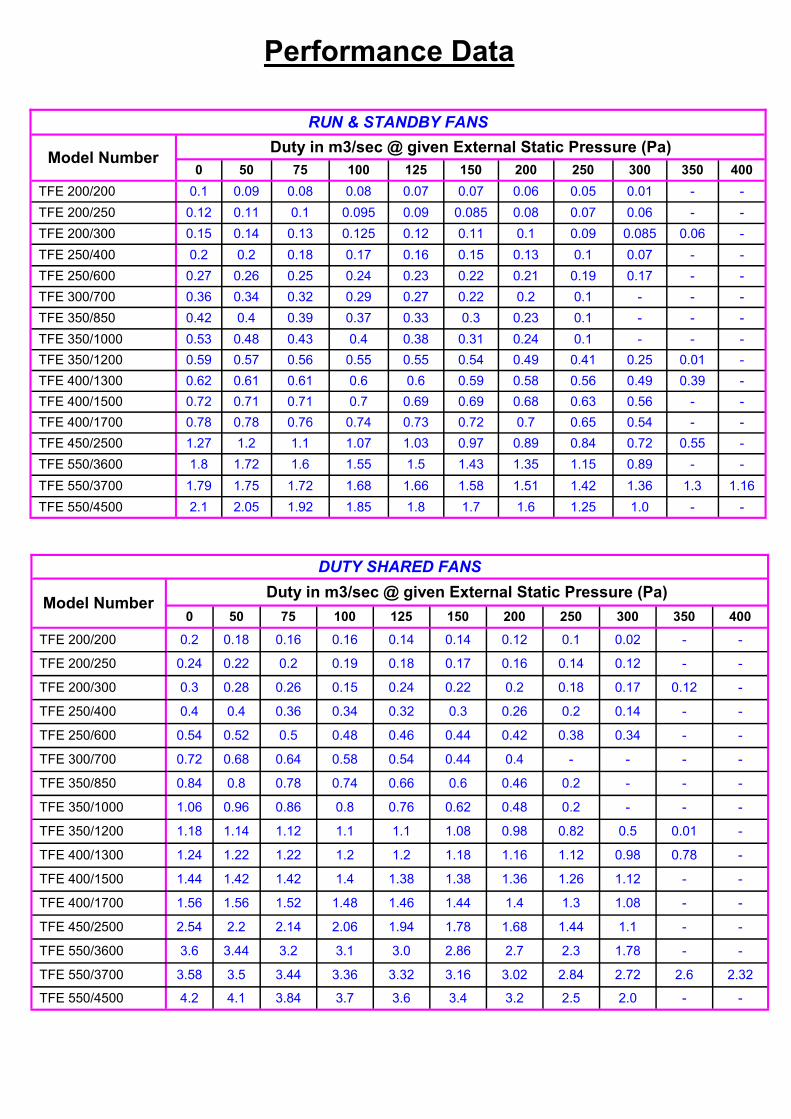
RUN & STANDBY FANS
Model Number Duty in m3/sec @ given External Static Pressure (Pa)
0 50 75 100 125 150 200 250 300 350 400
TFE 200/200 0.1 0.09 0.08 0.08 0.07 0.07 0.06 0.05 0.01 - -
TFE 200/250 0.12 0.11 0.1 0.095 0.09 0.085 0.08 0.07 0.06 - -
TFE 200/300 0.15 0.14 0.13 0.125 0.12 0.11 0.1 0.09 0.085 0.06 -
TFE 250/400 0.2 0.2 0.18 0.17 0.16 0.15 0.13 0.1 0.07 - -
TFE 250/600 0.27 0.26 0.25 0.24 0.23 0.22 0.21 0.19 0.17 - -
TFE 300/700 0.36 0.34 0.32 0.29 0.27 0.22 0.2 0.1 - - -
TFE 350/850 0.42 0.4 0.39 0.37 0.33 0.3 0.23 0.1 - - -
TFE 350/1000 0.53 0.48 0.43 0.4 0.38 0.31 0.24 0.1 - - -
TFE 350/1200 0.59 0.57 0.56 0.55 0.55 0.54 0.49 0.41 0.25 0.01 -
TFE 400/1300 0.62 0.61 0.61 0.6 0.6 0.59 0.58 0.56 0.49 0.39 -
TFE 400/1500 0.72 0.71 0.71 0.7 0.69 0.69 0.68 0.63 0.56 - -
TFE 400/1700 0.78 0.78 0.76 0.74 0.73 0.72 0.7 0.65 0.54 - -
TFE 450/2500 1.27 1.2 1.1 1.07 1.03 0.97 0.89 0.84 0.72 0.55 -
TFE 550/3600 1.8 1.72 1.6 1.55 1.5 1.43 1.35 1.15 0.89 - -
TFE 550/3700 1.79 1.75 1.72 1.68 1.66 1.58 1.51 1.42 1.36 1.3 1.16
TFE 550/4500 2.1 2.05 1.92 1.85 1.8 1.7 1.6 1.25 1.0 - -
Performance Data
DUTY SHARED FANS
Model Number Duty in m3/sec @ given External Static Pressure (Pa)
0 50 75 100 125 150 200 250 300 350 400
TFE 200/200 0.2 0.18 0.16 0.16 0.14 0.14 0.12 0.1 0.02 - -
TFE 200/250 0.24 0.22 0.2 0.19 0.18 0.17 0.16 0.14 0.12 - -
TFE 200/300 0.3 0.28 0.26 0.15 0.24 0.22 0.2 0.18 0.17 0.12 -
TFE 250/400 0.4 0.4 0.36 0.34 0.32 0.3 0.26 0.2 0.14 - -
TFE 250/600 0.54 0.52 0.5 0.48 0.46 0.44 0.42 0.38 0.34 - -
TFE 300/700 0.72 0.68 0.64 0.58 0.54 0.44 0.4 - - - -
TFE 350/850 0.84 0.8 0.78 0.74 0.66 0.6 0.46 0.2 - - -
TFE 350/1000 1.06 0.96 0.86 0.8 0.76 0.62 0.48 0.2 - - -
TFE 350/1200 1.18 1.14 1.12 1.1 1.1 1.08 0.98 0.82 0.5 0.01 -
TFE 400/1300 1.24 1.22 1.22 1.2 1.2 1.18 1.16 1.12 0.98 0.78 -
TFE 400/1500 1.44 1.42 1.42 1.4 1.38 1.38 1.36 1.26 1.12 - -
TFE 400/1700 1.56 1.56 1.52 1.48 1.46 1.44 1.4 1.3 1.08 - -
TFE 450/2500 2.54 2.2 2.14 2.06 1.94 1.78 1.68 1.44 1.1 - -
TFE 550/3600 3.6 3.44 3.2 3.1 3.0 2.86 2.7 2.3 1.78 - -
TFE 550/3700 3.58 3.5 3.44 3.36 3.32 3.16 3.02 2.84 2.72 2.6 2.32
TFE 550/4500 4.2 4.1 3.84 3.7 3.6 3.4 3.2 2.5 2.0 - -

Electrical and Sound Data
Model Number
Running Current per Fan Motor
(Amps)
Starting Current per Fan Motor
(Amps)
Power per Fan Motor
(Watts)
Induct Sound Power Levels dBW @ Octave Band Mid Frequency HZ
Noise Breakout Level dBA*
63 125 250 500 1K 2K 4K 8K SSK*** DSK***
TFE 200/200 0.3 0.75 67 32 34 46 55 56 54 51 50 40 25
TFE 200/250 0.44 1.1 99 25 29 38 43 39 40 34 26 36 21
TFE 200/300 0.8 2.0 105 63 57 55 54 54 47 41 32 44 29
TFE 250/400 0.8 2.0 190 40 44 46 52 52 50 45 41 41 26
TFE 250/600 1.2 3.0 273 68 62 61 61 59 54 47 37 48 33
TFE 300/700 1.5 3.75 92 79 77 70 68 65 61 53 46 49 34
TFE 350/850 1.9 4.75 184 67 69 70 69 66 62 59 54 44 29
TFE 350/1000 2.3 5.75 300 71 72 73 72 70 66 62 57 48 33
TFE 350/1200 4.3 10.75 350 75 72 67 63 61 60 58 45 50 35
TFE 400/1300 3.5 8.75 300 81 78 73 69 67 66 64 51 55 40
TFE 400/1500 4.4 11.0 420 72 70 62 60 56 53 46 37 46 31
TFE 400/1700 3.5 8.75 300 76 74 66 64 60 57 49 41 53 38
TFE 450/2500 6.8 17.5 550 80 78 70 68 64 61 53 45 61 46
TFE 550/3600 4.3** 21.5** 1100 87 84 82 81 79 75 67 55 64 49
TFE 550/3700 4.7** 23.5** 1500 87 88 89 88 86 82 78 73 71 56
TFE 550/4500 4.5** 22.5** 1100 79 76 74 72 67 64 58 48 62 47
* The dBA quoted is the mean ‘A’ weighted sound pressure level measured at a distance of 3m. It is included for comparative purposes only and the actual sound level experienced will depend on the acoustic characteristics of the area being served. Ductwork and Silencers also have a major influence on breakout noise and actual noise levels in the system. ** 380/415 V ac Three Phase Motor. *** To obtain sound levels for twin fans running together as duty shared, add 3dB to the sound figures above.
Typical Part Code:
W TFE 350 / 1200 - SC – R&S Weather proof Run & Standby Twin Fan Extract Speed Controller
Unit Size Twin Fan & Motor Size
Manual select switch for Fan 1 or Fan 2 operation. This can be used to balance the use of each fan to prolong their motor life.
Fan 1 and Fan 2 Run / Fail indication lamps.
Each fan fitted with Airflow micro switch as standard for fan run / fail indication to panel.
230Vac 1Ph mains supply required.
Deluxe Auto Changeover Panel
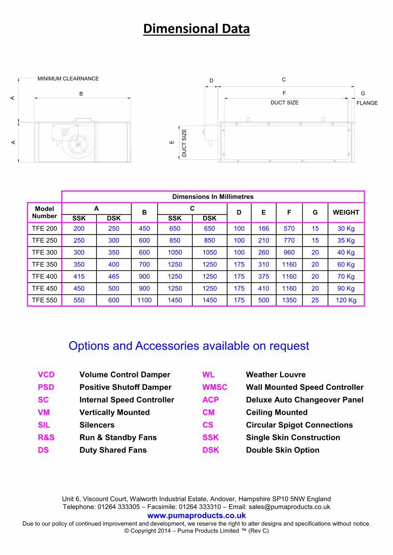
Dimensional Data
Dimensions In Millimetres
Model Number
A B
C D E F G WEIGHT
SSK DSK SSK DSK
TFE 200 200 250 450 650 650 100 166 570 15 30 Kg
TFE 250 250 300 600 850 850 100 210 770 15 35 Kg
TFE 300 300 350 600 1050 1050 100 260 960 20 40 Kg
TFE 350 350 400 700 1250 1250 175 310 1160 20 60 Kg
TFE 400 415 465 900 1250 1250 175 375 1160 20 70 Kg
TFE 450 450 500 900 1250 1250 175 410 1160 20 90 Kg
TFE 550 550 600 1100 1450 1450 175 500 1350 25 120 Kg
Options and Accessories available on request
VCD Volume Control Damper WL Weather Louvre
PSD Positive Shutoff Damper WMSC Wall Mounted Speed Controller
SC Internal Speed Controller ACP Deluxe Auto Changeover Panel
VM Vertically Mounted CM Ceiling Mounted
SIL Silencers CS Circular Spigot Connections
R&S Run & Standby Fans SSK Single Skin Construction
DS Duty Shared Fans DSK Double Skin Option
Unit 6, Viscount Court, Walworth Industrial Estate, Andover, Hampshire SP10 5NW England
Telephone: 01264 333305 – Facsimile: 01264 333310 – Email: [email protected] www.pumaproducts.co.uk
Due to our policy of continued improvement and development, we reserve the right to alter designs and specifications without notice.
© Copyright 2014 – Puma Products Limited ™ (Rev C)
MINIMUM CLEARNANCE
A
A B
D
E
F
C
G
FLANGE DUCT SIZE
DU
CT
SIZ
E