two-dimensional kinetic shape dynamics: verification...
TRANSCRIPT
Research ArticleTwo-Dimensional Kinetic Shape Dynamics:Verification and Application
Ismet Handzic,1 Haris Muratagic,2 and Kyle B. Reed2
1Tao Life Sciences, Greenville, SC, USA2The University of South Florida, Tampa, USA
Correspondence should be addressed to Kyle B. Reed; [email protected]
Received 4May 2016; Accepted 25 September 2016
Academic Editor:Thordur Runolfsson
Copyright © 2016 Ismet Handzic et al.This is an open access article distributed under the Creative Commons Attribution License,which permits unrestricted use, distribution, and reproduction in any medium, provided the original work is properly cited.
A kinetic shape (KS) is a smooth two- or three-dimensional shape that is defined by its predicted ground reaction forces as it ispressed onto a flat surface. A KS can be applied in anymechanical situation where position-dependent force redirection is required.Although previous work on KSs can predict static force reaction behavior, it does not describe the kinematic behavior of theseshapes. In this article, we derive the equations of motion for a rolling two-dimensional KS (or any other smooth curve) and validatethe model with physical experiments.The results of the physical experiments showed good agreement with the predicted dynamicKS model. In addition, we have modified these equations of motion to develop and verify the theory of a novel transportationdevice, the kinetic board, that is powered by an individual shifting their weight on top of a set of KSs.
1. Introduction
Throughout ancient and modern history, the mechanism ofrolling has been both useful and fascinating. The dynamicsof a circular object rolling down a slope is an elementaryand age-old mechanics concept and is often taught in earlymechanics courses.The equations of motion of a two dimen-sional circular object rolling down a slope is a commonphysics problem. However, a notion that has gained lessattention is the forced rolling of irregular objects or curves.The equations of motion that exactly dictate the rolling of ashape as a known force input is applied to its rotational axlehave not previously been developed.
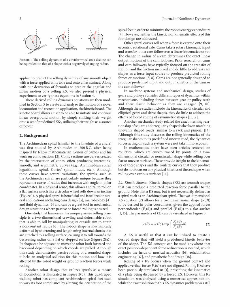
Dynamically, the behavior of such an asymmetric shapeunder forced conditions is similar to a circular shape rollingdown a ramp, as is shown in Figure 1. In all three instances,the rolling object is not in static equilibrium due to anunbalanced moment created by the applied force at the axlepoint.The rolling kinematics (!2"/!#2) of a circular wheel iscreated by a decreasing rolling surface height with distancetraveled (!$/!%), while the same rolling motion is createdfor a rounded object by a decreasing shape radius around the
object (relative to the axle point) (!&/!"). This generalizedcomparison is seen in!2"!#2 ∝ !$!% ∝ !&!" . (1)
Although we do have firm knowledge of how to exactlypredict the behavior of a wheel rolling down a ramp as a forceis applied to its axle (Lagrangian, Energy Method, etc.), thederivation of an arbitrary and asymmetric rolling curve in asimilar situation has largely been ignored.
The concept and approach of the kinetic shape (KS) [1]offer a way to analyze these types of dynamics problems.TheKS equation defines a smooth shape in static equilibriumthat can produce exact and predictable reaction forces whenforced onto a flat surface. The related concepts and back-ground of the KSs are discussed in Section 2.
Section 3 shows the derivations for the kinematic equa-tions that predict the angular kinematics of a two dimensionalKS rolling freely with a force applied to its axle. This sectionalso extends the KS concept from predicting a KS’s staticbehavior to deriving its dynamic behavior. Although thesederived equations of motion are used for KSs, they can be
Hindawi Publishing Corporation
Journal of Nonlinear Dynamics
Volume 2016, Article ID 8124015, 15 pages
http://dx.doi.org/10.1155/2016/8124015
2 Journal of Nonlinear Dynamics
FF F
==
Figure 1:The rolling dynamics of a circular wheel on a decline canbe equivalent to that of a shape with a negatively changing radius.
applied to predict the rolling dynamics of any smooth objectwith a force applied at its axle and onto a flat surface. Alongwith our derivation of formulas to predict the angular andlinear motion of a rolling KS, we also present a physicalexperiment to verify these equations in Section 4.
These derived rolling dynamics equations are then mod-ified in Section 5 to create and analyze the motion of a novellocomotion and recreation application, the kinetic board.Thekinetic board allows a user to be able to initiate and continuelinear overground motion by simply shifting their weightonto a set of predefined KSs, utilizing their weight as a sourceof power.
2. Background
The Archimedean spiral (similar to the involute of a circle)was first studied by Archimedes in 200B.C. after beinginspired by fellow mathematician Conon of Samos and hiswork on conic sections [2]. Conic sections are curves createdby the intersection of cones, often producing interesting,smooth, and asymmetric curves (e.g., Archimedean spiral,logarithmic spiral, Cortes’ spiral, lituus, etc.). Althoughthese curves have several variations, the spirals, such asthe Archimedes spiral, are particularly unique because theyrepresent a curve of radius that increases with angle in polarcoordinates. In a physical sense, this allows a spiral to roll ona flat surface much like a circular wheel rolls down an incline(Figure 1). A physical spiral is beneficial and is utilized in sev-eral applications including cam design [3], microbiology [4],and fluid dynamics [5] and can be a great tool in mechanicaldesign situations where passive or forced rolling is desired.
One study that harnesses this unique passive rolling prin-ciple is a two-dimensional crawling and deformable robotthat is able to roll by manipulating its outside rim to attaina nonconstant radius [6]. The robot’s shape is mechanicallydeformed by shortening and lengthening internal chords thatare attached to a rolling surface, causing it to roll towards thedecreasing radius on a flat or slopped surface (Figure 2(a)).Its shape can be adjusted to move the robot both forward andbackward depending on which chords are pulled. Althoughthis study demonstrates passive rolling of a rounded shape,it lacks an analytical solution for this motion and how it isaffected by the robot weight or ground reaction forces whilerolling.
Another robot design that utilizes spirals as a meansof locomotion is illustrated in Figure 2(b). This quadrupedwalking robot has compliant Archimedean spiral feet usedto vary its foot compliance by altering the orientation of the
spiral feet in order tominimize the robot’s energy expenditure[7]. However, neither the kinetic nor kinematic effects of thisfoot design are addressed.
Other spiral curves roll when a force is exerted onto theireccentric rotational axle. Cams take a rotary kinematic inputand transfer it to a cam follower as a linear kinematic output.The change in radius of a cam determines the exact linearoutput motions of the cam follower. Prior research on camsand cam followers have typically focused on the transfer ofmotion and the friction involved and do little to address camshapes as a force input source to produce predicted rollingforces or motions [3, 8]. Cams are not generally designed toproduce predefined input and output kinetics of the cam orthe cam follower.
In machine systems and mechanical design, studies ofgears and pulleys consider different types of dynamics withinmechanisms, including forces between gear or pulley teethand their elastic behavior as they are engaged [9, 10].Although these studies include the kinematics of circular andelliptical gears and drive shapes, they do little to address theeffects of forced rolling of asymmetric shapes [11, 12].
Another mechanics study related the exact meshing rela-tionship of square and irregularly shapedwheels onmatchingunevenly shaped roads (similar to a rack and pinion) [13].Although this study discusses the rolling kinematics of theirregular shapes to its predefined uneven road, the dynamicsforces acting on such a system were not taken into account.
In mathematics, there have been articles centered onroulettes, which are curves traced by points on a two-dimensional circular or noncircular shape while rolling overflat or uneven surfaces.These provide insight to the kinemat-ics of these shapes and the roulette curves that they producebut do not focus on any physical kinetics of these shapeswhenrolling over various surfaces [14].
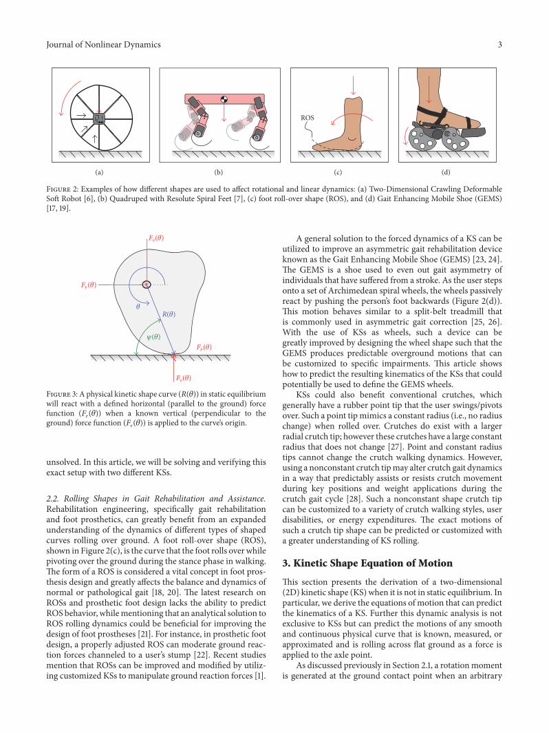
2.1. Kinetic Shapes. Kinetic shapes (KS) are smooth shapesthat can produce a predicted reaction force parallel to theground. Note that a KS may, but is not necessarily, defined asa spiral such as an Archimedean spiral.The two-dimensionalKS equation (2) allows for a two dimensional shape (&("))to be derived in polar coordinates, given the applied forcesperpendicular ((V(")) and parallel ((!(")) to a flat surface[1, 15].The parameters of (2) can be visualized in Figure 3& (") = & ("") exp∫ (V (")(! (")!". (2)
A KS is useful in that it can be utilized to create adesired shape that will yield a predefined kinetic behaviorof the shape. The KS concept can be used anywhere thatexact position-dependent force redirection is needed, whichincludes the fields of musical acoustics [16], rehabilitationengineering [17], and prosthetic foot design [18].
Rolling of a KS occurs when the ground contact andapplied vertical force ((V(")) are not aligned. RollingKSs havebeen previously simulated in [1], presenting the kinematicsof a plate being dispensed by a forced KS. However, this KSsimulation was analyzed using a numerical approximation,while the exact solution to this KS dynamics problemwas still
Journal of Nonlinear Dynamics 3
(a) (b)
ROS
(c) (d)
Figure 2: Examples of how different shapes are used to affect rotational and linear dynamics: (a) Two-Dimensional Crawling DeformableSoft Robot [6], (b) Quadruped with Resolute Spiral Feet [7], (c) foot roll-over shape (ROS), and (d) Gait Enhancing Mobile Shoe (GEMS)[17, 19].
Fr(!)
Fr(!)
!R(!)
Fv(!)
Fv(!)
"(!)
Figure 3: A physical kinetic shape curve (&(")) in static equilibriumwill react with a defined horizontal (parallel to the ground) forcefunction ((!(")) when a known vertical (perpendicular to theground) force function ((!(")) is applied to the curve’s origin.
unsolved. In this article, we will be solving and verifying thisexact setup with two different KSs.
2.2. Rolling Shapes in Gait Rehabilitation and Assistance.Rehabilitation engineering, specifically gait rehabilitationand foot prosthetics, can greatly benefit from an expandedunderstanding of the dynamics of different types of shapedcurves rolling over ground. A foot roll-over shape (ROS),shown in Figure 2(c), is the curve that the foot rolls over whilepivoting over the ground during the stance phase in walking.The form of a ROS is considered a vital concept in foot pros-thesis design and greatly affects the balance and dynamics ofnormal or pathological gait [18, 20]. The latest research onROSs and prosthetic foot design lacks the ability to predictROS behavior, whilementioning that an analytical solution toROS rolling dynamics could be beneficial for improving thedesign of foot prostheses [21]. For instance, in prosthetic footdesign, a properly adjusted ROS can moderate ground reac-tion forces channeled to a user’s stump [22]. Recent studiesmention that ROSs can be improved and modified by utiliz-ing customized KSs to manipulate ground reaction forces [1].
A general solution to the forced dynamics of a KS can beutilized to improve an asymmetric gait rehabilitation deviceknown as the Gait Enhancing Mobile Shoe (GEMS) [23, 24].The GEMS is a shoe used to even out gait asymmetry ofindividuals that have suffered from a stroke. As the user stepsonto a set of Archimedean spiral wheels, the wheels passivelyreact by pushing the person’s foot backwards (Figure 2(d)).This motion behaves similar to a split-belt treadmill thatis commonly used in asymmetric gait correction [25, 26].With the use of KSs as wheels, such a device can begreatly improved by designing the wheel shape such that theGEMS produces predictable overground motions that canbe customized to specific impairments. This article showshow to predict the resulting kinematics of the KSs that couldpotentially be used to define the GEMS wheels.
KSs could also benefit conventional crutches, whichgenerally have a rubber point tip that the user swings/pivotsover. Such a point tipmimics a constant radius (i.e., no radiuschange) when rolled over. Crutches do exist with a largerradial crutch tip; however these crutches have a large constantradius that does not change [27]. Point and constant radiustips cannot change the crutch walking dynamics. However,using a nonconstant crutch tipmay alter crutch gait dynamicsin a way that predictably assists or resists crutch movementduring key positions and weight applications during thecrutch gait cycle [28]. Such a nonconstant shape crutch tipcan be customized to a variety of crutch walking styles, userdisabilities, or energy expenditures. The exact motions ofsuch a crutch tip shape can be predicted or customized witha greater understanding of KS rolling.
3. Kinetic Shape Equation of Motion
This section presents the derivation of a two-dimensional(2D) kinetic shape (KS) when it is not in static equilibrium. Inparticular, we derive the equations of motion that can predictthe kinematics of a KS. Further this dynamic analysis is notexclusive to KSs but can predict the motions of any smoothand continuous physical curve that is known, measured, orapproximated and is rolling across flat ground as a force isapplied to the axle point.
As discussed previously in Section 2.1, a rotationmomentis generated at the ground contact point when an arbitrary
4 Journal of Nonlinear Dynamics
G
O
Fv(!)
Fv(!)
Fr(!)
Fr(!)
R(!)!
d2!dt2
"(!)
(a)
R()
dRd
()
(b)
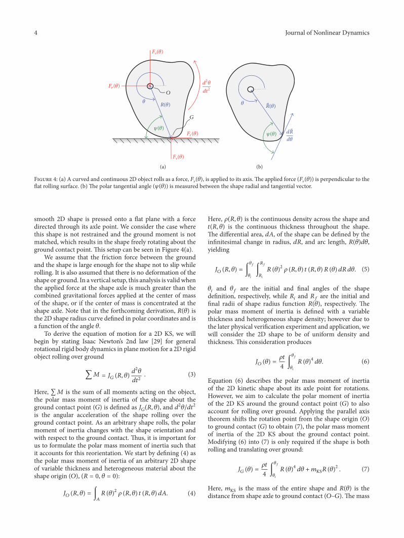
Figure 4: (a) A curved and continuous 2D object rolls as a force, (V("), is applied to its axis.The applied force ((V(")) is perpendicular to theflat rolling surface. (b)The polar tangential angle (,(")) is measured between the shape radial and tangential vector.
smooth 2D shape is pressed onto a flat plane with a forcedirected through its axle point. We consider the case wherethis shape is not restrained and the ground moment is notmatched, which results in the shape freely rotating about theground contact point.This setup can be seen in Figure 4(a).
We assume that the friction force between the groundand the shape is large enough for the shape not to slip whilerolling. It is also assumed that there is no deformation of theshape or ground. In a vertical setup, this analysis is validwhenthe applied force at the shape axle is much greater than thecombined gravitational forces applied at the center of massof the shape, or if the center of mass is concentrated at theshape axle. Note that in the forthcoming derivation, &(") isthe 2D shape radius curve defined in polar coordinates and isa function of the angle ".
To derive the equation of motion for a 2D KS, we willbegin by stating Isaac Newton’s 2nd law [29] for generalrotational rigid body dynamics in planemotion for a 2D rigidobject rolling over ground∑. = /# (&, ") !2"!#2 . (3)
Here, ∑. is the sum of all moments acting on the object,the polar mass moment of inertia of the shape about theground contact point (1) is defined as /#(&, "), and !2"/!#2is the angular acceleration of the shape rolling over theground contact point. As an arbitrary shape rolls, the polarmoment of inertia changes with the shape orientation andwith respect to the ground contact. Thus, it is important forus to formulate the polar mass moment of inertia such thatit accounts for this reorientation. We start by defining (4) asthe polar mass moment of inertia of an arbitrary 2D shapeof variable thickness and heterogeneous material about theshape origin (2), (& = 0, " = 0):/$ (&, ") = ∫% & (")2 3 (&, ") # (&, ") !4. (4)
Here, 3(&, ") is the continuous density across the shape and#(&, ") is the continuous thickness throughout the shape.The differential area, !4, of the shape can be defined by theinfinitesimal change in radius, !&, and arc length, &(")!",yielding/$ (&, ") = ∫&!&" ∫'!'" & (")2 3 (&, ") # (&, ")& (") !&!". (5)"" and "( are the initial and final angles of the shapedefinition, respectively, while &" and &( are the initial andfinal radii of shape radius function &("), respectively. Thepolar mass moment of inertia is defined with a variablethickness and heterogeneous shape density; however due tothe later physical verification experiment and application, wewill consider the 2D shape to be of uniform density andthickness.This consideration produces/$ (") = 3#4 ∫&!&" & (")4 !". (6)
Equation (6) describes the polar mass moment of inertiaof the 2D kinetic shape about its axle point for rotations.However, we aim to calculate the polar moment of inertiaof the 2D KS around the ground contact point (1) to alsoaccount for rolling over ground. Applying the parallel axistheorem shifts the rotation point from the shape origin (2)to ground contact (1) to obtain (7), the polar mass momentof inertia of the 2D KS about the ground contact point.Modifying (6) into (7) is only required if the shape is bothrolling and translating over ground:/# (") = 3#4 ∫&!&" & (")4 !" +5KS& (")2 . (7)
Here, 5KS is the mass of the entire shape and &(") is thedistance from shape axle to ground contact (2–1).The mass
Journal of Nonlinear Dynamics 5
of a 2D shape with a nonconstant density and thickness isdefined by 5KS = ∫% 3 (&, ") # (&, ") !4. (8)
Following similar steps and assumptions for a constant shapethickness and density, redefining the differential area !4,and integrating through the radial direction, the KS mass isredefined as 5KS = 3#2 ∫&2&1 & (")2 !". (9)
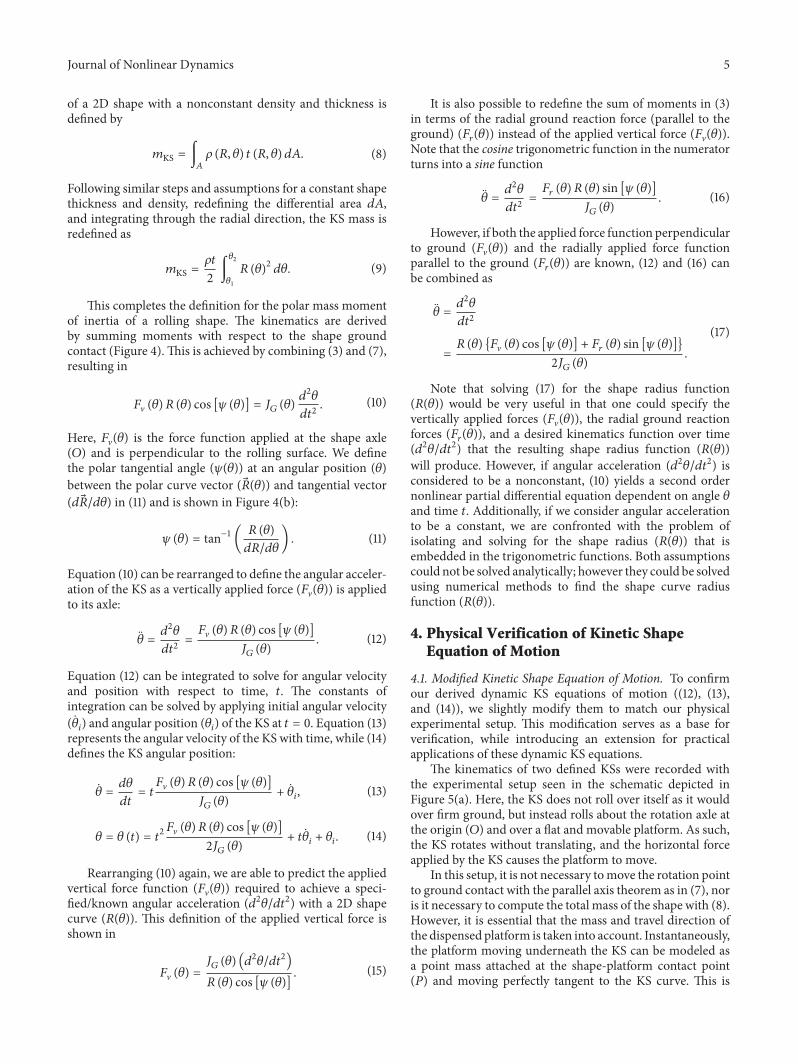
This completes the definition for the polar mass momentof inertia of a rolling shape. The kinematics are derivedby summing moments with respect to the shape groundcontact (Figure 4).This is achieved by combining (3) and (7),resulting in (V (")& (") cos [, (")] = /# (") !2"!#2 . (10)
Here, (V(") is the force function applied at the shape axle(2) and is perpendicular to the rolling surface. We definethe polar tangential angle (,(")) at an angular position (")between the polar curve vector (&(")) and tangential vector(!&/!") in (11) and is shown in Figure 4(b):, (") = tan−1 ( & (")!&/!") . (11)
Equation (10) can be rearranged to define the angular acceler-ation of the KS as a vertically applied force ((V(")) is appliedto its axle: " = !2"!#2 = (V (")& (") cos [, (")]/# (") . (12)
Equation (12) can be integrated to solve for angular velocityand position with respect to time, #. The constants ofintegration can be solved by applying initial angular velocity("") and angular position ("") of the KS at # = 0. Equation (13)represents the angular velocity of the KS with time, while (14)defines the KS angular position:" = !"!# = #(V (")& (") cos [, (")]/# (") + "", (13)
" = " (#) = #2(V (")& (") cos [, (")]2/# (") + #"" + "". (14)
Rearranging (10) again, we are able to predict the appliedvertical force function ((V(")) required to achieve a speci-fied/known angular acceleration (!2"/!#2) with a 2D shapecurve (&(")). This definition of the applied vertical force isshown in (V (") = /# (") (!2"/!#2)& (") cos [, (")] . (15)
It is also possible to redefine the sum of moments in (3)in terms of the radial ground reaction force (parallel to theground) ((!(")) instead of the applied vertical force ((V(")).Note that the cosine trigonometric function in the numeratorturns into a sine function" = !2"!#2 = (! (")& (") sin [, (")]/# (") . (16)
However, if both the applied force function perpendicularto ground ((V(")) and the radially applied force functionparallel to the ground ((!(")) are known, (12) and (16) canbe combined as" = !2"!#2= & (") {(V (") cos [, (")] + (! (") sin [, (")]}2/# (") . (17)
Note that solving (17) for the shape radius function(&(")) would be very useful in that one could specify thevertically applied forces ((V(")), the radial ground reactionforces ((!(")), and a desired kinematics function over time(!2"/!#2) that the resulting shape radius function (&("))will produce. However, if angular acceleration (!2"/!#2) isconsidered to be a nonconstant, (10) yields a second ordernonlinear partial differential equation dependent on angle "and time #. Additionally, if we consider angular accelerationto be a constant, we are confronted with the problem ofisolating and solving for the shape radius (&(")) that isembedded in the trigonometric functions. Both assumptionscould not be solved analytically; however they could be solvedusing numerical methods to find the shape curve radiusfunction (&(")).4. Physical Verification of Kinetic Shape
Equation of Motion
4.1. Modified Kinetic Shape Equation of Motion. To confirmour derived dynamic KS equations of motion ((12), (13),and (14)), we slightly modify them to match our physicalexperimental setup. This modification serves as a base forverification, while introducing an extension for practicalapplications of these dynamic KS equations.
The kinematics of two defined KSs were recorded withthe experimental setup seen in the schematic depicted inFigure 5(a). Here, the KS does not roll over itself as it wouldover firm ground, but instead rolls about the rotation axle atthe origin (2) and over a flat and movable platform. As such,the KS rotates without translating, and the horizontal forceapplied by the KS causes the platform to move.
In this setup, it is not necessary tomove the rotation pointto ground contact with the parallel axis theorem as in (7), noris it necessary to compute the total mass of the shape with (8).However, it is essential that the mass and travel direction ofthe dispensed platform is taken into account. Instantaneously,the platform moving underneath the KS can be modeled asa point mass attached at the shape-platform contact point(A) and moving perfectly tangent to the KS curve. This is
6 Journal of Nonlinear Dynamics
P
mApp
mPlat
g
(a)
O
Fr(!)
Fv(!)
d2!dt2
d2xdt2
R(!)
mPlat
F"(!) = mAppg
Ff(!, x)
#(!)
(b)
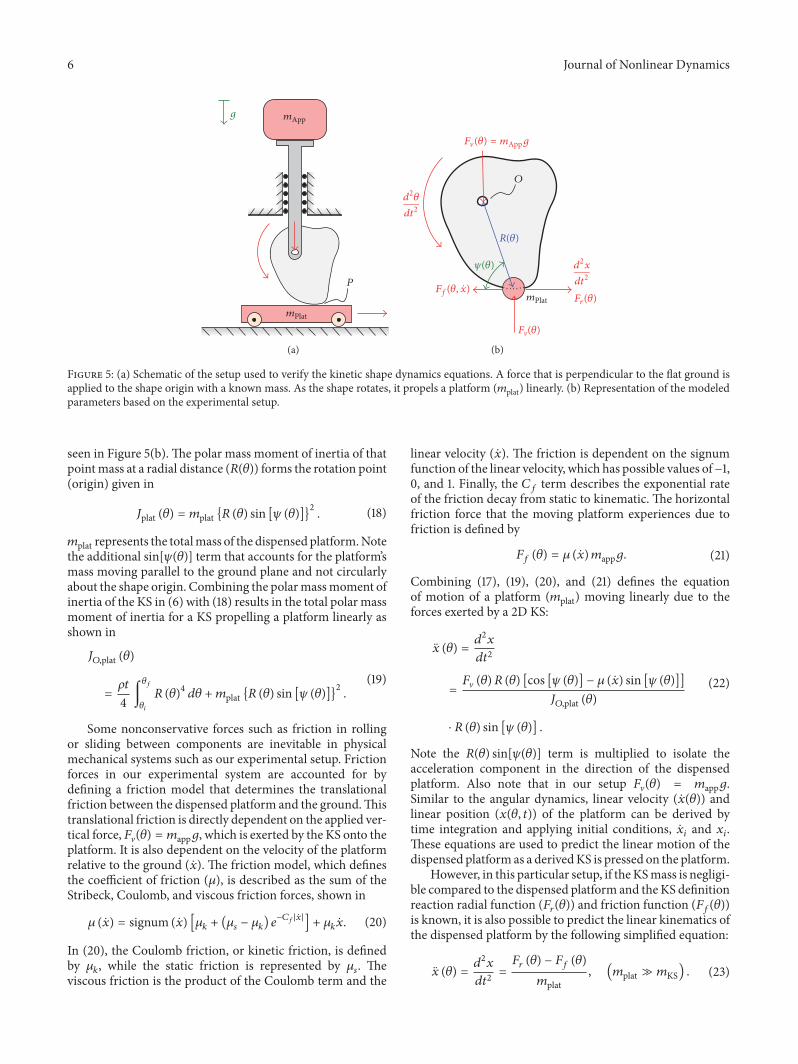
Figure 5: (a) Schematic of the setup used to verify the kinetic shape dynamics equations. A force that is perpendicular to the flat ground isapplied to the shape origin with a known mass. As the shape rotates, it propels a platform (5plat) linearly. (b) Representation of the modeledparameters based on the experimental setup.
seen in Figure 5(b).The polar mass moment of inertia of thatpointmass at a radial distance (&(")) forms the rotation point(origin) given in/plat (") = 5plat {& (") sin [, (")]}2 . (18)5plat represents the totalmass of the dispensed platform.Notethe additional sin[,(")] term that accounts for the platform’smass moving parallel to the ground plane and not circularlyabout the shape origin. Combining the polarmassmoment ofinertia of the KS in (6) with (18) results in the total polar massmoment of inertia for a KS propelling a platform linearly asshown in/$,plat (")= 3#4 ∫&!&" & (")4 !" +5plat {& (") sin [, (")]}2 . (19)
Some nonconservative forces such as friction in rollingor sliding between components are inevitable in physicalmechanical systems such as our experimental setup. Frictionforces in our experimental system are accounted for bydefining a friction model that determines the translationalfriction between the dispensed platform and the ground.Thistranslational friction is directly dependent on the applied ver-tical force,(V(") = 5appB, which is exerted by the KS onto theplatform. It is also dependent on the velocity of the platformrelative to the ground (%).The friction model, which definesthe coefficient of friction (C), is described as the sum of theStribeck, Coulomb, and viscous friction forces, shown inC (%) = signum (%) [C* + (C+ − C*) F−,!|.|] + C*%. (20)
In (20), the Coulomb friction, or kinetic friction, is definedby C*, while the static friction is represented by C+. Theviscous friction is the product of the Coulomb term and the
linear velocity (%). The friction is dependent on the signumfunction of the linear velocity, which has possible values of−1,0, and 1. Finally, the H( term describes the exponential rateof the friction decay from static to kinematic.The horizontalfriction force that the moving platform experiences due tofriction is defined by(( (") = C (%)5appB. (21)
Combining (17), (19), (20), and (21) defines the equationof motion of a platform (5plat) moving linearly due to theforces exerted by a 2D KS:% (") = !2%!#2= (V (")& (") [cos [, (")] − C (%) sin [, (")]]/$,plat (")⋅ & (") sin [, (")] .
(22)
Note the &(") sin[,(")] term is multiplied to isolate theacceleration component in the direction of the dispensedplatform. Also note that in our setup (V(") = 5appB.Similar to the angular dynamics, linear velocity (%(")) andlinear position (%(", #)) of the platform can be derived bytime integration and applying initial conditions, %" and %".These equations are used to predict the linear motion of thedispensed platform as a derivedKS is pressed on the platform.
However, in this particular setup, if theKSmass is negligi-ble compared to the dispensed platform and the KS definitionreaction radial function ((!(")) and friction function (((("))is known, it is also possible to predict the linear kinematics ofthe dispensed platform by the following simplified equation:% (") = !2%!#2 = (! (") − (( (")5plat , (5plat ≫ 5KS) . (23)
Journal of Nonlinear Dynamics 7
Kine
tic sh
ape 1
Forc
e (ne
wton
s)
Kine
tic sh
ape 2
Forc
e (ne
wton
s)
80
60
40
20
0100
50
0
−50
−100
Radial force function, Fr(!)
No reactionforce point
No reactionforce point
Angular position, ! (radians)
Release angular positionFinal angular position
0 %/2
%/2
%/2
%
%
%
3%/2
3%/2 3%/22%
2%
2%
!
!
Shape definition, R(!)
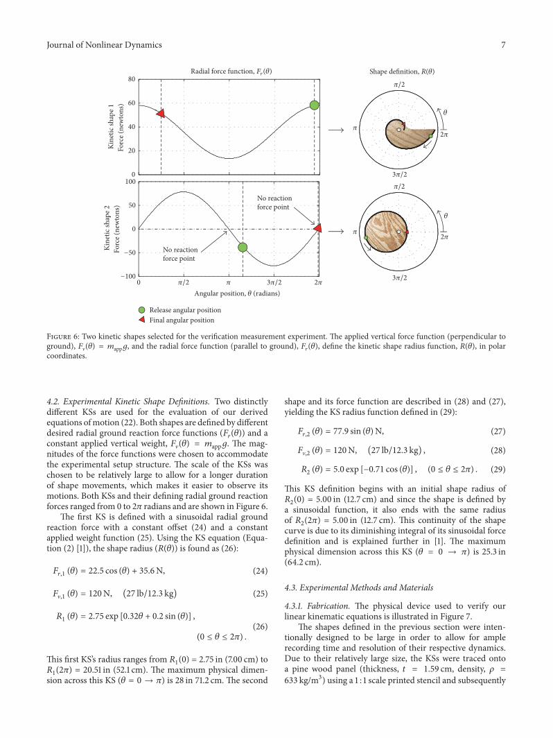
Figure 6: Two kinetic shapes selected for the verification measurement experiment. The applied vertical force function (perpendicular toground), (V(") = 5appB, and the radial force function (parallel to ground), (!("), define the kinetic shape radius function, &("), in polarcoordinates.
4.2. Experimental Kinetic Shape Definitions. Two distinctlydifferent KSs are used for the evaluation of our derivedequations ofmotion (22). Both shapes are defined by differentdesired radial ground reaction force functions ((!(")) and aconstant applied vertical weight, (V(") = 5appB. The mag-nitudes of the force functions were chosen to accommodatethe experimental setup structure. The scale of the KSs waschosen to be relatively large to allow for a longer durationof shape movements, which makes it easier to observe itsmotions. Both KSs and their defining radial ground reactionforces ranged from 0 to 2K radians and are shown in Figure 6.
The first KS is defined with a sinusoidal radial groundreaction force with a constant offset (24) and a constantapplied weight function (25). Using the KS equation (Equa-tion (2) [1]), the shape radius (&(")) is found as (26):(!,1 (") = 22.5 cos (") + 35.6N, (24)(V,1 (") = 120N, (27 lb/12.3 kg) (25)&1 (") = 2.75 exp [0.32" + 0.2 sin (")] , (0 ≤ " ≤ 2K) . (26)This first KS’s radius ranges from &1(0) = 2.75 in (7.00 cm) to&1(2K) = 20.51 in (52.1 cm). The maximum physical dimen-sion across this KS (" = 0 → K) is 28 in 71.2 cm.The second
shape and its force function are described in (28) and (27),yielding the KS radius function defined in (29):(!,2 (") = 77.9 sin (")N, (27)(V,2 (") = 120N, (27 lb/12.3 kg) , (28)&2 (") = 5.0 exp [−0.71 cos (")] , (0 ≤ " ≤ 2K) . (29)
This KS definition begins with an initial shape radius of&2(0) = 5.00 in (12.7 cm) and since the shape is defined bya sinusoidal function, it also ends with the same radiusof &2(2K) = 5.00 in (12.7 cm). This continuity of the shapecurve is due to its diminishing integral of its sinusoidal forcedefinition and is explained further in [1]. The maximumphysical dimension across this KS (" = 0 → K) is 25.3 in(64.2 cm).
4.3. Experimental Methods and Materials
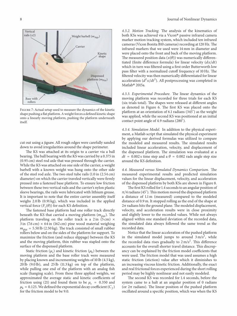
4.3.1. Fabrication. The physical device used to verify ourlinear kinematic equations is illustrated in Figure 7.
The shapes defined in the previous section were inten-tionally designed to be large in order to allow for amplerecording time and resolution of their respective dynamics.Due to their relatively large size, the KSs were traced ontoa pine wood panel (thickness, # = 1.59 cm, density, 3 =633 kg/m3) using a 1 : 1 scale printed stencil and subsequently
8 Journal of Nonlinear Dynamics
Verticalrails (x2) Weight barbell (mApp)
Carrier
Kineticshape
Dispensedplatform (mPlat)
Base withrollers
Figure 7: Actual setup used to measure the dynamics of the kineticshape pushing aflat platform.Aweight forces a defined kinetic shapeonto a linearly moving platform, pushing the platform underneathitself.
cut out using a jigsaw. All rough edges were carefully sandeddown to avoid irregularities around the shape perimeter.
The KS was attached at its origin to a carrier via a ballbearing.The ball bearingwith the KSwas carried by a 0.375 in(0.95 cm) steel rod axle that was pressed through the carrier.While the KS was attached on one side of the carrier, a weightbarbell with a known weight was hung onto the other sideof the steel rod axle.The two steel tube rails (1.0 in (2.54 cm)diameter) on which the carrier traveled vertically were firmlypressed into a fastened base platform. To ensure low frictionbetween these two vertical rails and the carrier’s nylon plasticsleeve bearings, the rails were lubricated with lithium grease.It is important to note that the entire carrier assembly itselfweighs 2.0 lb (0.91 kg), which was included in the appliedvertical force ((V(")) for each KS definition.
The fastened base platform had one roller track directlybeneath the KS that carried a moving platform (5plat). Theplatform traveling on the roller track is a 2 in (5 cm) ×3 in (7.6 cm) × 64 in (162 cm) pine wood material weighing5plat = 5.50 lb (2.50 kg). The track consisted of small rubberrollers below and on the sides of the platform for support. Tomaximize the friction (and reduce slippage) between the KSand the moving platform, thin rubber was stapled onto thesurface of the dispensed platform.
Static friction (C+) and kinetic friction (C*) between themoving platform and the base roller track were measuredby placing known and incrementing weights of 10 lb (4.5 kg),20 lb (9.0 lb), and 25 lb (11.3 kg) on top of the platform,while pulling one end of the platform with an analog fishscale (hanging scale). From these three applied weights, weapproximated the average static and kinetic coefficients offriction using (21) and found them to be C+ = 0.350 andC* = 0.125.We defined the exponential decay coefficient (H()for the friction model to be 9.0.
4.3.2. Motion Tracking. The analysis of the kinematics ofboth KSs was achieved via a Vicon! passive infrared cameramarker motion tracking system, which included ten infraredcameras (Vicon Bonita B10 cameras) recording at 120Hz.Theinfrared markers that we used were 14mm in diameter andwere placed onto the front and back of the moving platform.The measured position data (%(")) was numerically differen-tiated (finite difference formula) for linear velocity (!%/!#)which in turn was filtered using a first order Butterworth lowpass filter with a normalized cutoff frequency of 10Hz. Thefiltered velocity was then numerically differentiated for linearacceleration (!2%/!#2). All postprocessing was completed inMatlab! 2015a.
4.3.3. Experimental Procedure. The linear dynamics of themoving platform was recorded for three trials for each KS(six trials total). The shapes were released at different anglesas denoted in Figure 6. The first KS was placed onto theplatform at an orientation of 6.1 radians (345∘) as the weightwas applied, while the second KS was positioned at an initialcontact point angle of 4.9 radians (280∘).4.3.4. Simulation Model. In addition to the physical experi-ment, a Matlab script that simulated the physical experimentby applying our derived formulas was utilized to comparethe modeled and measured results. The simulated resultsincluded linear acceleration, velocity, and displacement ofthe dispensed platform. The simulation was evaluated at a!# = 0.002 s time step and a " = 0.002 rads angle step sizearound the KS definition.
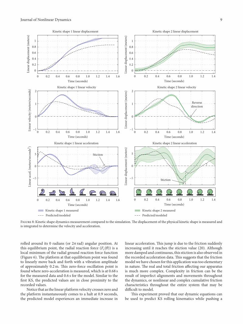
4.4. Measured versus Simulated Dynamics Comparison. Themeasured experimental results and predicted simulationvalues for the linear displacement, velocity, and accelerationof the dispensed platform by both KSs are shown in Figure 8.
The first KS rolled for 1.4 seconds to an angular position ofK/4 radians (45∘).This motionmoved the dispensed platforma distance of 1.1m (measured) compared to the modeleddistance of 0.9m. It stopped rolling as the end of the shape at2K radians hits the ground plane.The modeled displacement,velocity, and acceleration results were in close proximityand slightly lower to the recorded values. While not alwaysaligned within one standard deviation of the recorded data,the simulated data always followed the same trend as therecorded data.
Notice that the linear acceleration of the pushed platformin the simulated model jumps to around 3m/s2, whilethe recorded data rises gradually to 2m/s2. This differenceaccounts for the overall shorter travel distance.This discrep-ancy can be explained by the friction model coefficients thatwere used. The friction model that was used assumes a highstatic friction (stiction) value after which it diminishes toan increasing viscous kinetic friction. Additionally, the exactand real frictional forces experienced during the short rollingperiod may be highly nonlinear and not easily modeled.
The second KS was recorded for 1.4 seconds, before thesystem came to a halt at an angular position of 0 radians(or 2K radians). The linear position of the pushed platformoscillated around a specific position, which was when the KS
Journal of Nonlinear Dynamics 9
Line
ar d
isplac
emen
t (m
eter
s)
0
0.2
0.4
0.6
0.8
1
Kinetic shape 1 linear displacementLi
near
velo
city (
met
ers/s
econ
ds)
−1
0
1
2Kinetic shape 1 linear velocity
Time (seconds)
−5
0
5
Kinetic shape 1 linear acceleration
Line
ar d
isplac
emen
t (m
eter
s)
−5
0
5
Kinetic shape 2 linear acceleration
Line
ar d
isplac
emen
t (m
eter
s)−1
0
1
2Kinetic shape 2 linear velocity
Line
ar d
isplac
emen
t (m
eter
s)
0
0.2
0.4
0.6
0.8
1
Kinetic shape 2 linear displacementLi
near
acce
l. (m
eter
s/sec
onds
2 )
Stiction
Stiction
0 0.2 0.4 0.6 0.8 1.0 1.2 1.4Time (seconds)
0 0.2 0.4 0.6 0.8 1.0 1.2 1.4
Time (seconds)0 0.2 0.4 0.6 0.8 1.0 1.2 1.4
Time (seconds)0 0.2 0.4 0.6 0.8 1.0 1.2 1.4
1.6
Time (seconds)0 0.2 0.4 0.6 0.8 1.0 1.2 1.4 1.6
Time (seconds)0 0.2 0.4 0.6 0.8 1.0 1.2 1.4 1.6
Reversedirection
Kinetic shape 1 measured Kinetic shape 2 measuredPredicted/modeled Predicted/modeled
Figure 8: Kinetic shape dynamics measurement compared to the simulation.The displacement of the physical kinetic shape is measured andis integrated to determine the velocity and acceleration.
rolled around its 0 radians (or 2K rad) angular position. Atthis equilibrium point, the radial reaction force ((!(")) is alocal minimum of the radial ground reaction force function(Figure 6).The platform at that equilibrium point was foundto linearly move back and forth with a vibration amplitudeof approximately 0.2m. This zero-force oscillation point isfound where zero-acceleration is measured, which is at 0.68 sfor the measured data and 0.6 s for the model. Similar to thefirst KS, the predicted values are in close proximity to therecorded values.
Notice that as the linear platformvelocity crosses zero andthe platform instantaneously comes to a halt at 0.9 seconds,the predicted model experiences an immediate increase in
linear acceleration.This jump is due to the friction suddenlyincreasing until it reaches the stiction value (20). Althoughmore damped and continuous, this stiction is also observed inthe recorded acceleration data.This suggests that the frictionmodel we have chosen for this applicationwas too elementaryin nature. The real and total friction affecting our apparatusis much more complex. Complexity in friction can be theresult of imperfect alignments and movements throughoutthe dynamics, or nonlinear and complex cumulative frictioncharacteristics throughout the entire system that may bedifficult to model.
This experiment proved that our dynamic equations canbe used to predict KS rolling kinematics while pushing a
10 Journal of Nonlinear Dynamics
Back KS Rolls Front KS RollsfreelyfreelyBoost force, FrB(!) Boost force, FrF(!)
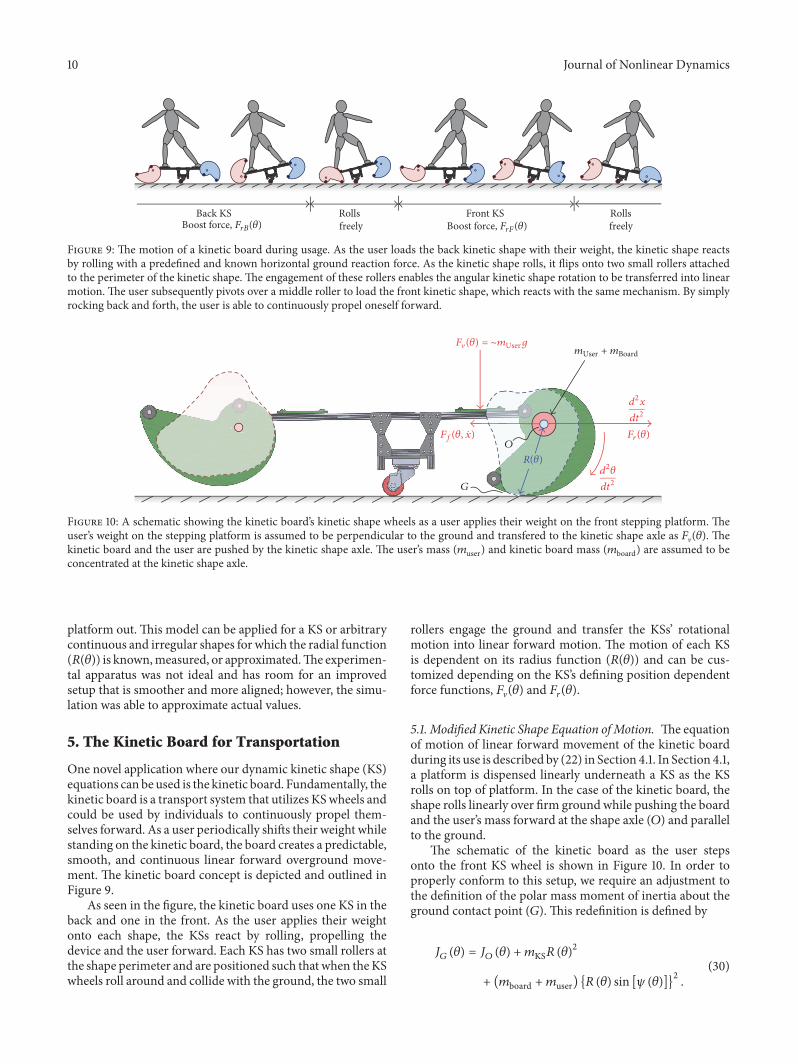
Figure 9: The motion of a kinetic board during usage. As the user loads the back kinetic shape with their weight, the kinetic shape reactsby rolling with a predefined and known horizontal ground reaction force. As the kinetic shape rolls, it flips onto two small rollers attachedto the perimeter of the kinetic shape.The engagement of these rollers enables the angular kinetic shape rotation to be transferred into linearmotion.The user subsequently pivots over a middle roller to load the front kinetic shape, which reacts with the same mechanism. By simplyrocking back and forth, the user is able to continuously propel oneself forward.
Ff(!, x)
d2!dt2
d2xdt2
Fr(!)O
G
F"(!) = ∼mUserg mUser + mBoard
R(!)
Figure 10: A schematic showing the kinetic board’s kinetic shape wheels as a user applies their weight on the front stepping platform. Theuser’s weight on the stepping platform is assumed to be perpendicular to the ground and transfered to the kinetic shape axle as (V("). Thekinetic board and the user are pushed by the kinetic shape axle. The user’s mass (5user) and kinetic board mass (5board) are assumed to beconcentrated at the kinetic shape axle.
platform out.This model can be applied for a KS or arbitrarycontinuous and irregular shapes for which the radial function(&(")) is known,measured, or approximated.The experimen-tal apparatus was not ideal and has room for an improvedsetup that is smoother and more aligned; however, the simu-lation was able to approximate actual values.
5. The Kinetic Board for Transportation
One novel application where our dynamic kinetic shape (KS)equations can be used is the kinetic board. Fundamentally, thekinetic board is a transport system that utilizes KSwheels andcould be used by individuals to continuously propel them-selves forward. As a user periodically shifts their weight whilestanding on the kinetic board, the board creates a predictable,smooth, and continuous linear forward overground move-ment. The kinetic board concept is depicted and outlined inFigure 9.
As seen in the figure, the kinetic board uses one KS in theback and one in the front. As the user applies their weightonto each shape, the KSs react by rolling, propelling thedevice and the user forward. Each KS has two small rollers atthe shape perimeter and are positioned such that when theKSwheels roll around and collide with the ground, the two small
rollers engage the ground and transfer the KSs’ rotationalmotion into linear forward motion. The motion of each KSis dependent on its radius function (&(")) and can be cus-tomized depending on the KS’s defining position dependentforce functions, (V(") and (!(").5.1. Modified Kinetic Shape Equation of Motion. The equationof motion of linear forward movement of the kinetic boardduring its use is described by (22) in Section 4.1. In Section 4.1,a platform is dispensed linearly underneath a KS as the KSrolls on top of platform. In the case of the kinetic board, theshape rolls linearly over firm ground while pushing the boardand the user’s mass forward at the shape axle (2) and parallelto the ground.
The schematic of the kinetic board as the user stepsonto the front KS wheel is shown in Figure 10. In order toproperly conform to this setup, we require an adjustment tothe definition of the polar mass moment of inertia about theground contact point (1).This redefinition is defined by
/# (") = /$ (") +5KS& (")2+ (5board +5user) {& (") sin [, (")]}2 . (30)
Journal of Nonlinear Dynamics 11
Back
KS w
heel
Forc
e (ne
wton
s)Fr
ont K
S whe
elFo
rce (
newt
ons)
300
200
100
0200
150
100
0
50
Radial force function, Fr(!)
Angular position, ! (radians)0 %/2
%/2
%/2
%
%
%
3%/2
3%/2
3%/2 2%
2%
2%
!
!
Shape definition, R(!)
Initial angular positionFinal angular position
Ground lineat roller strike
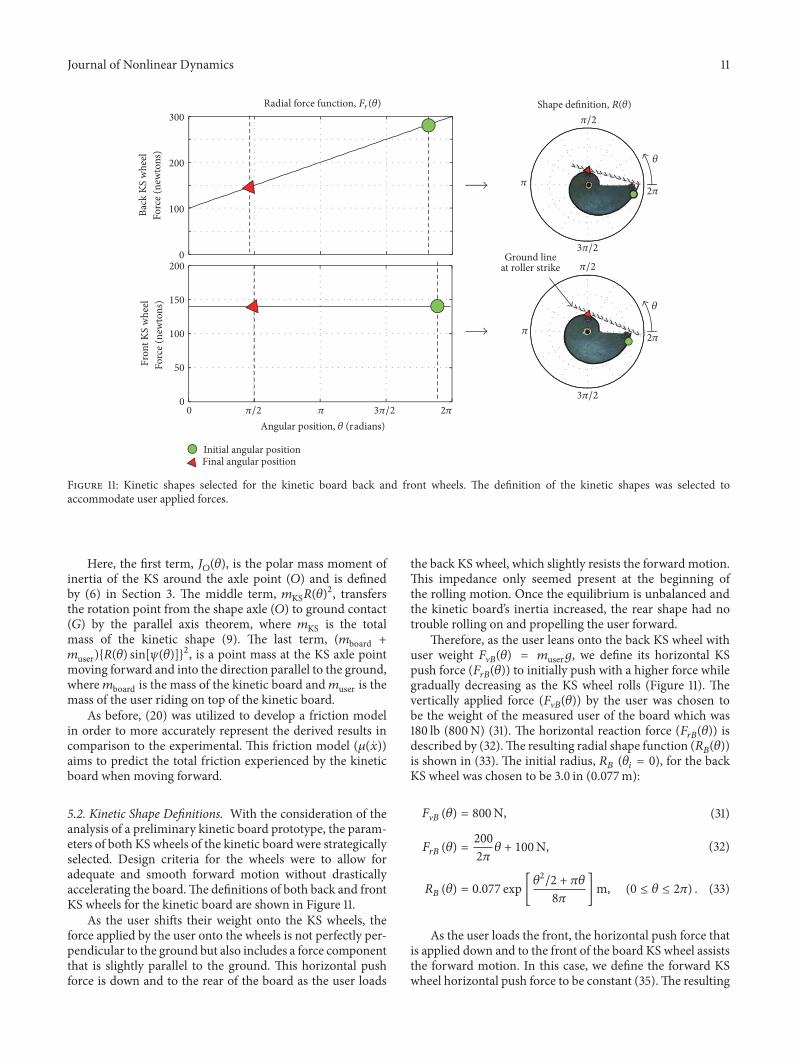
Figure 11: Kinetic shapes selected for the kinetic board back and front wheels. The definition of the kinetic shapes was selected toaccommodate user applied forces.
Here, the first term, /$("), is the polar mass moment ofinertia of the KS around the axle point (2) and is definedby (6) in Section 3. The middle term, 5KS&(")2, transfersthe rotation point from the shape axle (2) to ground contact(1) by the parallel axis theorem, where 5KS is the totalmass of the kinetic shape (9). The last term, (5board +5user){&(") sin[,(")]}2, is a point mass at the KS axle pointmoving forward and into the direction parallel to the ground,where5board is the mass of the kinetic board and5user is themass of the user riding on top of the kinetic board.
As before, (20) was utilized to develop a friction modelin order to more accurately represent the derived results incomparison to the experimental. This friction model (C(%))aims to predict the total friction experienced by the kineticboard when moving forward.
5.2. Kinetic Shape Definitions. With the consideration of theanalysis of a preliminary kinetic board prototype, the param-eters of both KS wheels of the kinetic board were strategicallyselected. Design criteria for the wheels were to allow foradequate and smooth forward motion without drasticallyaccelerating the board.The definitions of both back and frontKS wheels for the kinetic board are shown in Figure 11.
As the user shifts their weight onto the KS wheels, theforce applied by the user onto the wheels is not perfectly per-pendicular to the ground but also includes a force componentthat is slightly parallel to the ground. This horizontal pushforce is down and to the rear of the board as the user loads
the back KS wheel, which slightly resists the forward motion.This impedance only seemed present at the beginning ofthe rolling motion. Once the equilibrium is unbalanced andthe kinetic board’s inertia increased, the rear shape had notrouble rolling on and propelling the user forward.
Therefore, as the user leans onto the back KS wheel withuser weight (V0(") = 5userB, we define its horizontal KSpush force ((!0(")) to initially push with a higher force whilegradually decreasing as the KS wheel rolls (Figure 11). Thevertically applied force ((V0(")) by the user was chosen tobe the weight of the measured user of the board which was180 lb (800N) (31). The horizontal reaction force ((!0(")) isdescribed by (32).The resulting radial shape function (&0("))is shown in (33). The initial radius, &0 ("" = 0), for the backKS wheel was chosen to be 3.0 in (0.077m):(V0 (") = 800N, (31)(!0 (") = 2002K " + 100N, (32)
&0 (") = 0.077 exp["2/2 + K"8K ]m, (0 ≤ " ≤ 2K) . (33)
As the user loads the front, the horizontal push force thatis applied down and to the front of the board KS wheel assiststhe forward motion. In this case, we define the forward KSwheel horizontal push force to be constant (35).The resulting
12 Journal of Nonlinear Dynamics
Back KSwheel
Steppingsurface
Resetspring
Reset pulleywith stopper
KS rollerwheel
Pivot (middle)roller
Front KSwheel
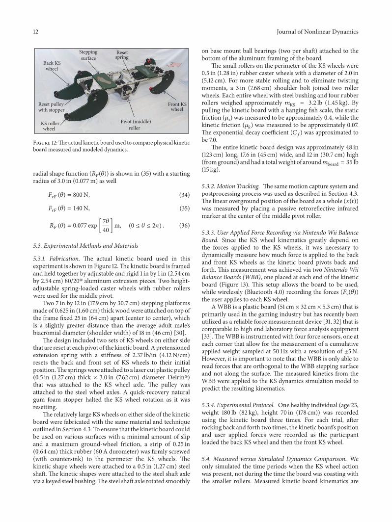
Figure 12:The actual kinetic board used to compare physical kineticboard measured and modeled dynamics.
radial shape function (&1(")) is shown in (35) with a startingradius of 3.0 in (0.077m) as well(V1 (") = 800N, (34)(!1 (") = 140N, (35)&1 (") = 0.077 exp [7"40]m, (0 ≤ " ≤ 2K) . (36)
5.3. Experimental Methods and Materials
5.3.1. Fabrication. The actual kinetic board used in thisexperiment is shown in Figure 12.The kinetic board is framedand held together by adjustable and rigid 1 in by 1 in (2.54 cmby 2.54 cm) 80/20! aluminum extrusion pieces. Two height-adjustable spring-loaded caster wheels with rubber rollerswere used for the middle pivot.
Two 7 in by 12 in (17.9 cm by 30.7 cm) stepping platformsmade of 0.625 in (1.60 cm) thickwoodwere attached on top ofthe frame fixed 25 in (64 cm) apart (center to center), whichis a slightly greater distance than the average adult male’sbiacromial diameter (shoulder width) of 18 in (46 cm) [30].
The design included two sets of KS wheels on either sidethat are reset at each pivot of the kinetic board.Apretensionedextension spring with a stiffness of 2.37 lb/in (4.12N/cm)resets the back and front set of KS wheels to their initialposition.The springswere attached to a laser cut plastic pulley(0.5 in (1.27 cm) thick × 3.0 in (7.62 cm) diameter Delrin!)that was attached to the KS wheel axle. The pulley wasattached to the steel wheel axles. A quick-recovery naturalgum foam stopper halted the KS wheel rotation as it wasresetting.
The relatively large KS wheels on either side of the kineticboard were fabricated with the same material and techniqueoutlined in Section 4.3. To ensure that the kinetic board couldbe used on various surfaces with a minimal amount of slipand a maximum ground-wheel friction, a strip of 0.25 in(0.64 cm) thick rubber (60A durometer) was firmly screwed(with countersink) to the perimeter the KS wheels. Thekinetic shape wheels were attached to a 0.5 in (1.27 cm) steelshaft. The kinetic shapes were attached to the steel shaft axlevia a keyed steel bushing.The steel shaft axle rotated smoothly
on base mount ball bearings (two per shaft) attached to thebottom of the aluminum framing of the board.
The small rollers on the perimeter of the KS wheels were0.5 in (1.28 in) rubber caster wheels with a diameter of 2.0 in(5.12 cm). For more stable rolling and to eliminate twistingmoments, a 3 in (7.68 cm) shoulder bolt joined two rollerwheels. Each entire wheel with steel bushing and four rubberrollers weighed approximately 5KS = 3.2 lb (1.45 kg). Bypulling the kinetic board with a hanging fish scale, the staticfriction (C+) was measured to be approximately 0.4, while thekinetic friction (C*) was measured to be approximately 0.07.The exponential decay coefficient (H() was approximated tobe 7.0.
The entire kinetic board design was approximately 48 in(123 cm) long, 17.6 in (45 cm) wide, and 12 in (30.7 cm) high(fromground) andhad a totalweight of around5board = 35 lb(15 kg).
5.3.2. Motion Tracking. The samemotion capture system andpostprocessing process was used as described in Section 4.3.The linear overground position of the board as a whole (%(#))was measured by placing a passive retroreflective infraredmarker at the center of the middle pivot roller.
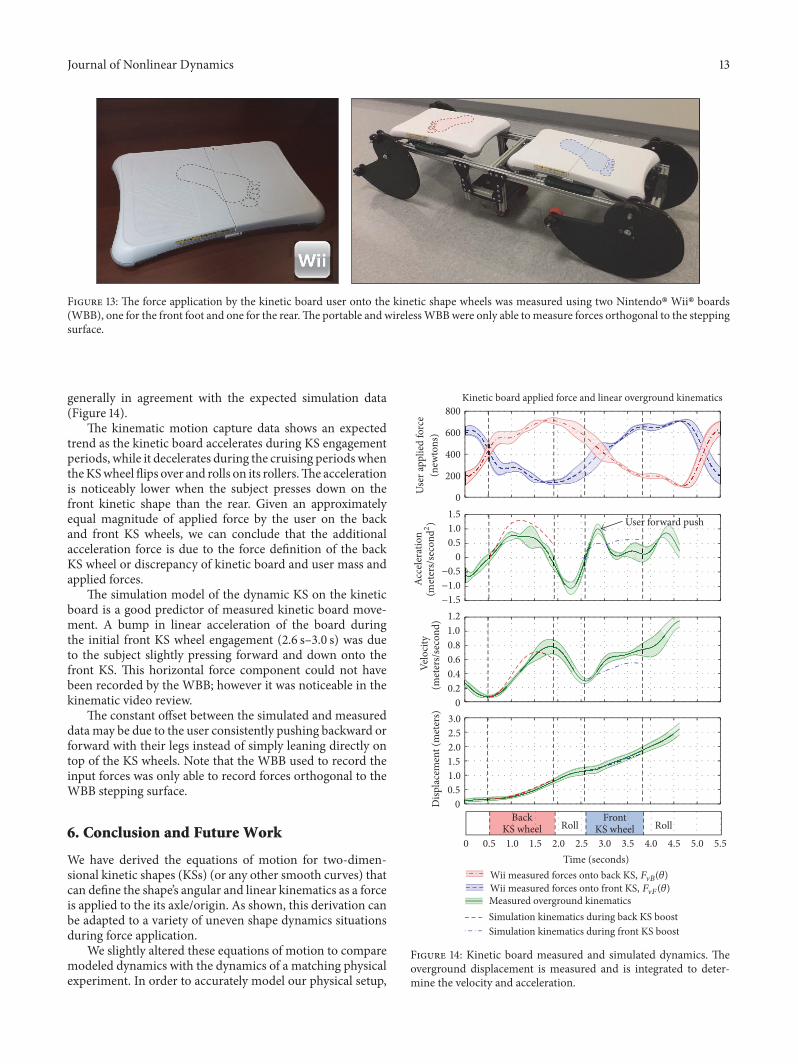
5.3.3. User Applied Force Recording via Nintendo Wii BalanceBoard. Since the KS wheel kinematics greatly depend onthe forces applied to the KS wheels, it was necessary todynamically measure how much force is applied to the backand front KS wheels as the kinetic board pivots back andforth.This measurement was achieved via two Nintendo WiiBalance Boards (WBB), one placed at each end of the kineticboard (Figure 13). This setup allows the board to be used,while wirelessly (Bluetooth 4.0) recording the forces ((V("))the user applies to each KS wheel.
A WBB is a plastic board (51 cm × 32 cm × 5.3 cm) that isprimarily used in the gaming industry but has recently beenutilized as a reliable force measurement device [31, 32] that iscomparable to high end laboratory force analysis equipment[33].TheWBB is instrumented with four force sensors, one ateach corner that allow for the measurement of a cumulativeapplied weight sampled at 50Hz with a resolution of ±5N.However, it is important to note that the WBB is only able toread forces that are orthogonal to the WBB stepping surfaceand not along the surface. The measured kinetics from theWBB were applied to the KS dynamics simulation model topredict the resulting kinematics.
5.3.4. Experimental Protocol. One healthy individual (age 23,weight 180 lb (82 kg), height 70 in (178 cm)) was recordedusing the kinetic board three times. For each trial, afterrocking back and forth two times, the kinetic board’s positionand user applied forces were recorded as the participantloaded the back KS wheel and then the front KS wheel.
5.4. Measured versus Simulated Dynamics Comparison. Weonly simulated the time periods when the KS wheel actionwas present, not during the time the board was coasting withthe smaller rollers. Measured kinetic board kinematics are
Journal of Nonlinear Dynamics 13
Figure 13: The force application by the kinetic board user onto the kinetic shape wheels was measured using two Nintendo! Wii! boards(WBB), one for the front foot and one for the rear.The portable and wirelessWBBwere only able tomeasure forces orthogonal to the steppingsurface.
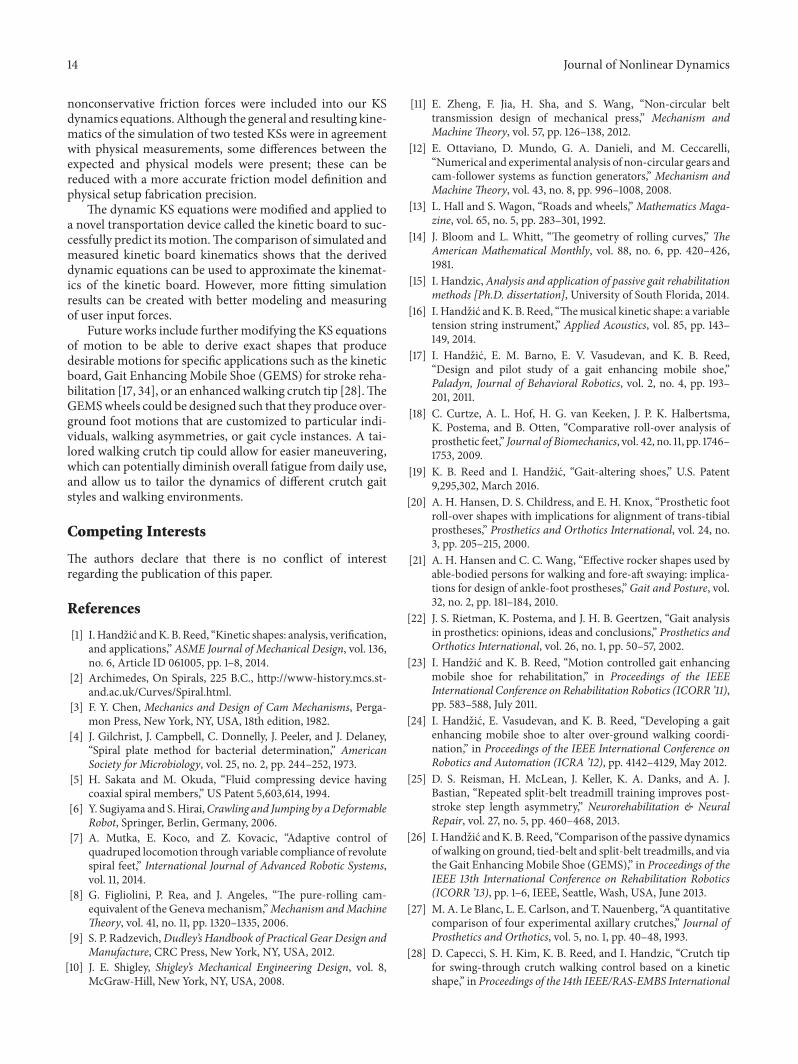
generally in agreement with the expected simulation data(Figure 14).
The kinematic motion capture data shows an expectedtrend as the kinetic board accelerates during KS engagementperiods, while it decelerates during the cruising periods whentheKSwheelflips over and rolls on its rollers.The accelerationis noticeably lower when the subject presses down on thefront kinetic shape than the rear. Given an approximatelyequal magnitude of applied force by the user on the backand front KS wheels, we can conclude that the additionalacceleration force is due to the force definition of the backKS wheel or discrepancy of kinetic board and user mass andapplied forces.
The simulation model of the dynamic KS on the kineticboard is a good predictor of measured kinetic board move-ment. A bump in linear acceleration of the board duringthe initial front KS wheel engagement (2.6 s–3.0 s) was dueto the subject slightly pressing forward and down onto thefront KS. This horizontal force component could not havebeen recorded by the WBB; however it was noticeable in thekinematic video review.
The constant offset between the simulated and measureddata may be due to the user consistently pushing backward orforward with their legs instead of simply leaning directly ontop of the KS wheels. Note that the WBB used to record theinput forces was only able to record forces orthogonal to theWBB stepping surface.
6. Conclusion and Future Work
We have derived the equations of motion for two-dimen-sional kinetic shapes (KSs) (or any other smooth curves) thatcan define the shape’s angular and linear kinematics as a forceis applied to the its axle/origin. As shown, this derivation canbe adapted to a variety of uneven shape dynamics situationsduring force application.
We slightly altered these equations of motion to comparemodeled dynamics with the dynamics of a matching physicalexperiment. In order to accurately model our physical setup,
0
200
400
600
800
−1.5−1.0−0.5
00.51.01.5
00.20.40.60.81.01.2
0 0.5 1.0 1.5 2.0 2.5 3.0 3.5 4.0 4.5 5.0 5.5
00.51.01.52.02.53.0
Time (seconds)
Roll RollFront
KS wheel
Disp
lacem
ent (
met
ers)
User
appl
ied fo
rce
(new
tons
)Ac
celer
atio
n(m
eter
s/se
cond
2 )Ve
locit
y(m
eter
s/sec
ond)
BackKS wheel
Wii measured forces onto back KS, F"B(!)Wii measured forces onto front KS, F"F(!)Measured overground kinematicsSimulation kinematics during back KS boostSimulation kinematics during front KS boost
Kinetic board applied force and linear overground kinematics
User forward push
Figure 14: Kinetic board measured and simulated dynamics. Theoverground displacement is measured and is integrated to deter-mine the velocity and acceleration.
14 Journal of Nonlinear Dynamics
nonconservative friction forces were included into our KSdynamics equations.Although the general and resulting kine-matics of the simulation of two tested KSs were in agreementwith physical measurements, some differences between theexpected and physical models were present; these can bereduced with a more accurate friction model definition andphysical setup fabrication precision.
The dynamic KS equations were modified and applied toa novel transportation device called the kinetic board to suc-cessfully predict itsmotion.The comparison of simulated andmeasured kinetic board kinematics shows that the deriveddynamic equations can be used to approximate the kinemat-ics of the kinetic board. However, more fitting simulationresults can be created with better modeling and measuringof user input forces.
Future works include furthermodifying the KS equationsof motion to be able to derive exact shapes that producedesirable motions for specific applications such as the kineticboard, Gait Enhancing Mobile Shoe (GEMS) for stroke reha-bilitation [17, 34], or an enhancedwalking crutch tip [28].TheGEMSwheels could be designed such that they produce over-ground foot motions that are customized to particular indi-viduals, walking asymmetries, or gait cycle instances. A tai-lored walking crutch tip could allow for easier maneuvering,which can potentially diminish overall fatigue from daily use,and allow us to tailor the dynamics of different crutch gaitstyles and walking environments.
Competing Interests
The authors declare that there is no conflict of interestregarding the publication of this paper.
References
[1] I.Handzic andK. B. Reed, “Kinetic shapes: analysis, verification,and applications,” ASME Journal of Mechanical Design, vol. 136,no. 6, Article ID 061005, pp. 1–8, 2014.
[2] Archimedes, On Spirals, 225 B.C., http://www-history.mcs.st-and.ac.uk/Curves/Spiral.html.
[3] F. Y. Chen, Mechanics and Design of Cam Mechanisms, Perga-mon Press, New York, NY, USA, 18th edition, 1982.
[4] J. Gilchrist, J. Campbell, C. Donnelly, J. Peeler, and J. Delaney,“Spiral plate method for bacterial determination,” AmericanSociety for Microbiology, vol. 25, no. 2, pp. 244–252, 1973.
[5] H. Sakata and M. Okuda, “Fluid compressing device havingcoaxial spiral members,” US Patent 5,603,614, 1994.
[6] Y. Sugiyama and S.Hirai,Crawling and Jumping by aDeformableRobot, Springer, Berlin, Germany, 2006.
[7] A. Mutka, E. Koco, and Z. Kovacic, “Adaptive control ofquadruped locomotion through variable compliance of revolutespiral feet,” International Journal of Advanced Robotic Systems,vol. 11, 2014.
[8] G. Figliolini, P. Rea, and J. Angeles, “The pure-rolling cam-equivalent of the Genevamechanism,”Mechanism andMachineTheory, vol. 41, no. 11, pp. 1320–1335, 2006.
[9] S. P. Radzevich,Dudley’s Handbook of Practical Gear Design andManufacture, CRC Press, New York, NY, USA, 2012.
[10] J. E. Shigley, Shigley’s Mechanical Engineering Design, vol. 8,McGraw-Hill, New York, NY, USA, 2008.
[11] E. Zheng, F. Jia, H. Sha, and S. Wang, “Non-circular belttransmission design of mechanical press,” Mechanism andMachineTheory, vol. 57, pp. 126–138, 2012.
[12] E. Ottaviano, D. Mundo, G. A. Danieli, and M. Ceccarelli,“Numerical and experimental analysis of non-circular gears andcam-follower systems as function generators,” Mechanism andMachineTheory, vol. 43, no. 8, pp. 996–1008, 2008.
[13] L. Hall and S. Wagon, “Roads and wheels,”Mathematics Maga-zine, vol. 65, no. 5, pp. 283–301, 1992.
[14] J. Bloom and L. Whitt, “The geometry of rolling curves,” TheAmerican Mathematical Monthly, vol. 88, no. 6, pp. 420–426,1981.
[15] I. Handzic,Analysis and application of passive gait rehabilitationmethods [Ph.D. dissertation], University of South Florida, 2014.
[16] I. Handzic andK. B. Reed, “Themusical kinetic shape: a variabletension string instrument,” Applied Acoustics, vol. 85, pp. 143–149, 2014.
[17] I. Handzic, E. M. Barno, E. V. Vasudevan, and K. B. Reed,“Design and pilot study of a gait enhancing mobile shoe,”Paladyn, Journal of Behavioral Robotics, vol. 2, no. 4, pp. 193–201, 2011.
[18] C. Curtze, A. L. Hof, H. G. van Keeken, J. P. K. Halbertsma,K. Postema, and B. Otten, “Comparative roll-over analysis ofprosthetic feet,” Journal of Biomechanics, vol. 42, no. 11, pp. 1746–1753, 2009.
[19] K. B. Reed and I. Handzic, “Gait-altering shoes,” U.S. Patent9,295,302, March 2016.
[20] A. H. Hansen, D. S. Childress, and E. H. Knox, “Prosthetic footroll-over shapes with implications for alignment of trans-tibialprostheses,” Prosthetics and Orthotics International, vol. 24, no.3, pp. 205–215, 2000.
[21] A. H. Hansen and C. C. Wang, “Effective rocker shapes used byable-bodied persons for walking and fore-aft swaying: implica-tions for design of ankle-foot prostheses,” Gait and Posture, vol.32, no. 2, pp. 181–184, 2010.
[22] J. S. Rietman, K. Postema, and J. H. B. Geertzen, “Gait analysisin prosthetics: opinions, ideas and conclusions,” Prosthetics andOrthotics International, vol. 26, no. 1, pp. 50–57, 2002.
[23] I. Handzic and K. B. Reed, “Motion controlled gait enhancingmobile shoe for rehabilitation,” in Proceedings of the IEEEInternational Conference on Rehabilitation Robotics (ICORR ’11),pp. 583–588, July 2011.
[24] I. Handzic, E. Vasudevan, and K. B. Reed, “Developing a gaitenhancing mobile shoe to alter over-ground walking coordi-nation,” in Proceedings of the IEEE International Conference onRobotics and Automation (ICRA ’12), pp. 4142–4129, May 2012.
[25] D. S. Reisman, H. McLean, J. Keller, K. A. Danks, and A. J.Bastian, “Repeated split-belt treadmill training improves post-stroke step length asymmetry,” Neurorehabilitation & NeuralRepair, vol. 27, no. 5, pp. 460–468, 2013.
[26] I.Handzic andK. B. Reed, “Comparison of the passive dynamicsof walking on ground, tied-belt and split-belt treadmills, and viathe Gait EnhancingMobile Shoe (GEMS),” in Proceedings of theIEEE 13th International Conference on Rehabilitation Robotics(ICORR ’13), pp. 1–6, IEEE, Seattle, Wash, USA, June 2013.
[27] M. A. Le Blanc, L. E. Carlson, and T. Nauenberg, “A quantitativecomparison of four experimental axillary crutches,” Journal ofProsthetics and Orthotics, vol. 5, no. 1, pp. 40–48, 1993.
[28] D. Capecci, S. H. Kim, K. B. Reed, and I. Handzic, “Crutch tipfor swing-through crutch walking control based on a kineticshape,” in Proceedings of the 14th IEEE/RAS-EMBS International
Journal of Nonlinear Dynamics 15
Conference on Rehabilitation Robotics (ICORR ’15), pp. 612–617,Singapore, August 2015.
[29] I. Newton, F. Cajori, R. T. Crawford, and A. Motte, Sir IsaacNewton’s Mathematical Principles of Natural Philosophy andHis System of the World, Edited by R. T. Crawford, Universityof California Press, Translated by M. Andrew in 1729, TheTranslations Revised and Supplied with an Historical andExplanatory Appendix by Florian Cajori, 1934.
[30] H. W. Stoudt, A. Damon, R. McFarland et al., Skinfolds,Body Girths, Biacromial Diameter, and Selected AnthropometricIndices of Adults, United States, 1960–1962, US Health Servicesand Mental Health Administration, 1970.
[31] D. J. Goble, B. L. Cone, and B. W. Fling, “Using the Wii Fitas a tool for balance assessment and neurorehabilitation: thefirst half decade of ‘wii-search’,” Journal of NeuroEngineering andRehabilitation, vol. 11, no. 1, article 12, 2014.
[32] I. Handzic and K. B. Reed, “Analysis of human stepping dynam-ics using a Wii balance board with a webcam: a comparisonstudy,” in Proceedings of the 8th ACM International Conferenceon Pervasive Technologies Related to Assistive Environments, p.52, Curfu, Greece, July 2015.
[33] A. Huurnink, D. P. Fransz, I. Kingma, and J. H. van Dieen,“Comparison of a laboratory grade force platform with a Nin-tendo Wii Balance Board on measurement of postural controlin single-leg stance balance tasks,” Journal of Biomechanics, vol.46, no. 7, pp. 1392–1395, 2013.
[34] S. H. Kim, I. Handzic, D. Huizenga et al., “Initial results of thegait enhancing mobile shoe on individuals with stroke,” in Pro-ceedings of the International Conference of the IEEE EngineeringinMedicine and Biology Society (EMBC ’16), Orlando, Fla, USA,2016.