two-dimensional orthotropic plate analysis for an integral
TRANSCRIPT

Two-Dimensional Orthotropic Plate Analysis for an IntegralThermal Protection System
Oscar Martinez,∗ Bhavani Sankar,† and Raphael Haftka‡
University of Florida, Gainesville, Florida 32611
and
Max L. Blosser§
NASA Langley Research Center, Hampton, Virginia 23681
DOI: 10.2514/1.J051172
This paper is concernedwith homogenization of a corrugated-core sandwich panel, which is a candidate structure
for integrated thermal protection systems for space vehicles. The focus is on determining the local stresses in an
integrated thermal protection system panel subjected to mechanical and thermal loads. A micromechanical method
is developed to homogenize the sandwich panel as an equivalent orthotropic plate.Mechanical and thermal loads are
applied to the equivalent thick plate, and the resulting plate deformations were obtained through a shear deformable
plate theory. The two-dimensional plate deformations are used to obtain local integrated thermal protection system
stresses through reverse homogenization. In addition, simple beam models are used to obtain local facesheet
deformations and stress. The local stresses and deflections computed using the analytical method were compared
with those from a detailed finite element analysis of the integrated thermal protection system. For the integrated
thermal protection system examples considered in this paper, the maximum error in stresses and deflections is less
than 5%. This was true for both mechanical and thermal loads acting on the integrated thermal protection system.
Nomenclature
a = integrated thermal protection system lengthb = integrated thermal protection system widthd = height of sandwich panel (centerline to centerline)�D = inverse bending stiffness matrixD� = reduced bending stiffness matrixE = Young’s modulusEI = equivalent flexural rigidityG = transverse shear modulusPz = pressure load acting on the two-dimensional
orthotropic panelfqg = displacement vectorQij = transformed lamina stiffness matrixQx, Qy = shear force on unit cell�Qij = transformed lamina stiffness matrix in the
nonprincipal coordinate systems = web lengthtBF = bottom facesheet thicknesstTF = top facesheet thicknesstw = web thickness�TD��e� = deformation transformation matrix of the ith
component of the corrugated coreU = unit-cell strain energyv = deflection of beamw = integrated thermal protection system panel deflection
�yf = local y axis of facesheet�yw = local y axis of web�zf = local z axis of facesheet�zw = local z axis of web"o = midplane strain� = angle of web inclination� = curvature� = roots of auxiliary equation� = Poisson’s ratio x, y = rotations of the plate’s cross section2p = unit-cell length
I. Introduction
T HE primary function of a thermal protection system (TPS) is toprotect the space vehicle from extreme aerodynamic heating
and to maintain the underlying structure within acceptable temper-ature and mechanical constraints [1]. The current state-of-the-artreusable TPS covers the outer surface of a vehicle with a layer thatdoes not carry significant loads but prevents the underlying load-bearing structure from exceeding acceptable temperature limits.
An intriguing alternative is to embed the relatively fragileinsulation in a structural load-bearing sandwich panel. A robust,structural facesheet would then form the outer surface of the vehicle,thereby potentially removing some vehicle operational constraints,e.g., flight through rain, and reducing required maintenance. Byusing the insulation thickness as a structural sandwich core, there is apotential to increase structural bending stiffness, save weight, andreduce overall thickness of the vehicle wall. There are significantchallenges in designing a structure to function simultaneously as anefficient aerospace load-bearing structure and a thermal insulator.The challenges include understanding the key thermal-structuralloads and requirements that drive the design, identifying materialsthat best perform in a thermal environment, and accommodatingthermal expansion mismatches, thermal stresses, and effects oftemperature-dependent properties inherent in these systems. Candi-date concepts comprising metallic foams and innovative corematerials, such as corrugated and truss cores, have been investigated.
The corrugated-core sandwich panel is composed of several unitcells placed adjacent to each other. The empty space in the corrugatedcorewill be filled with a non-load-bearing insulation such as Safill®.The TPS concept combines all three passive TPS concepts: heat sink,
Received 13 January 2011; revision received 29August 2011; accepted forpublication 31 August 2011. Copyright © 2011 by the American Institute ofAeronautics and Astronautics, Inc. Copies of this paper may be made forpersonal or internal use, on condition that the copier pay the $10.00 per-copyfee to the Copyright Clearance Center, Inc., 222 Rosewood Drive, Danvers,MA 01923; include the code 0001-1452/12 and $10.00 in correspondencewith the CCC.
∗Structural Analyst, Department of Mechanical and Aerospace Engineer-ing; Jacobs Engineering, Engineering Science Contract Group, Houston,Texas.
†Ebaugh Professor, Department of Mechanical and Aerospace Engineer-ing. Associate Fellow AIAA.
‡Distinguished Professor, Department of Mechanical and AerospaceEngineering. Fellow AIAA.
§Aerospace Technologist, Metals and Thermal Structures Branch,Structural Concepts and Mechanics Branch.
AIAA JOURNALVol. 50, No. 2, February 2012
387

hot structure, and insulated structure [2]. The sandwich structurewillreplace the structural skin and the insulation in the current thermalstructures. Since the sandwich construction is stiffer than single skinconstruction, the number of frames and stringers will be significantlyreduced. Furthermore, the insulation is protected from foreign objectimpact and requires less or no maintenance such as waterproofing.The integral TPS/structure [integrated thermal protection system(ITPS)] design (Fig. 1) can significantly reduce the overall weight ofthe vehicle as the TPS/structure performs the load-bearing function.The ITPS is expected to bemultifunctional (offer insulation aswell asload-bearing capability). Advantages of an ITPS concept have beenidentified by Martinez et al. [3].
The finite element method (FEM) is commonly used to performthree-dimensional (3-D) stress analysis of the ITPS structure. How-ever, a full-scale 3-D finite element (FE) stress analysis will beexpensive and time-consuming for a quick preliminary sizing anal-ysis of an ITPS. The same is true with design optimization, whichmay involve 1000s of analyses. An alternative is tomodel the ITPS asan equivalent orthotropic plate and perform a 2-D plate analysis toobtain the displacement and stress fields.
This paper is the third in the sequel of paperswritten by the authorson the subject of homogenization of the ITPS. The procedures aredepicted in Fig. 1a. The ITPS, which consists of repeating cells, ishomogenized as an equivalent orthotropic plate, and the ABDmatrices (stiffness matrices) of the equivalent plate are calculatedusing analytical methods. In the first paper [3], the authors describedthe homogenization procedures and verified the accuracy of theextensional �A�, bending �D�, and shear �C� stiffness matrices bycomparing with those calculated using FEMs. In the second paper[4], procedures for calculating equivalent thermal forces andmoments for a given through-the-thickness temperature distributionwere developed without considering shear deformations. In the
current paper, the equivalent orthotropic plate is analyzed using afirst-order shear deformable theory in which the transverse shearstresses are not neglected. Both pressure loads and thermal loads areconsidered. The plate analysis results include midplane strains f"0gand curvatures f�g at a given �x; y�. Then, a reverse homogenizationprocedure is used to calculate the detailed stress field from the f"0gand f�g obtained from the plate analysis. The stresses are comparedwith those obtained from a detailed 3-D analysis of the ITPS.
It is worth pointing out that, in the present work, analyticalmethods are used for every step of the procedures described above.Analytical methods are much faster than FE analysis and are suitablewhen 1000s of analyses have to be performed in the design opti-mization of the ITPS panel. Analytical methods will be extremelyuseful if one decides to use stochastic optimization rather than asafety-factor-based design approach.
Only a limited amount of work in micromechanical unit-cellanalyses of sandwich structures is available in the literature [5–12]; ithas been summarized in our previous works [3,4] and will not berepeated here. The aforementioned researchers used the force-distortion relationship, which involvedmechanics of materials equa-tions to determine average unit-cell stresses. In the current paper, weimprove on that by use of a first-order shear deformable plate theory(FSDT) [13] for the 2-D equivalent ITPS plate analysis, reversehomogenization, and simple beam models for the local ITPS stressanalysis. The higher-order theory that includes the effects oftransverse shear deformation is suitable for an ITPS because of thesignificant transverse shear loads that are carried by the corrugatedcore. Although such stresses can be postcomputed through 3-Delasticity equilibrium equations, they are not always accurate. Theclassical laminate plate theory (CLPT) [14] underpredicts deflectionsand overpredicts buckling loads with plate length-to-thickness ratiosless than 20. For this reason alone, it was necessary to use the
Fig. 1 ITPS: a) corrugated-core sandwich panels for use as an ITPS and b) flowchart depicting procedures in homogenization of the ITPS panel and
reverse homogenization to obtain the detailed displacements and stresses (TFS denotes top facesheet; BFS denotes bottom facesheet).
388 MARTINEZ ETAL.

first-order theory in the ITPS analysis of relatively thick plates. Theprimary objective and importance of using the FSDTwhen analyzingthe ITPS as a two-dimensional (2-D) homogenized platewas to bringout the effect of shear deformation on deflections and stresses.
The paper’s objective is to derive a satisfactory approximate platetheory of an ITPS panel homogenized as a 2-D plate using the FSDT.The solution of the plate equations gives all necessary information forcalculating stresses at any point of the thick plate. Local ITPS stressesof the facesheets and webs are derived by using the 2-D platedeflections w, rotations, x, y, reverse homogenization, and atransformation matrix. Reverse homogenization only captures themidplane strains and curvatures of the unit cell at the origin (seeFig. 2),which resulted in a uniform stress field in the facesheets and webs.Additional local analysis had to be done through one-dimensional (1-D) beammodels to capture the nonuniform stressfield of the facesheetand webs when subjected to mechanical and thermal loads. The ITPSpanel is subjected to a uniform pressure load and thermal edgemoments, and the resulting plate deflections and local ITPS stressesare compared with a detailed FE analysis of the ITPS.
II. Analysis
Consider a simplified geometry of an ITPS unit cell, shown inFig. 2. The z axis is in the thickness direction of the ITPS panel. Thestiffer longitudinal direction is parallel to the x axis, and the y axis isin the transverse direction. The unit cell consists of two inclinedwebsand two thin facesheets. The unit cell is symmetric with respect tothe yz plane. The upper faceplate thickness tTF can be different fromthe lower faceplate thickness tTB, as well as the web thickness tw.The unit cell can be identified by six geometric parameters�p; d; tTF; tBF; tw; �� (Fig. 2).
The equivalent stiffness of the orthotropic plate is obtained bycomparing the behavior of a unit cell of the corrugated-core sandwichpanel with that of an element of the idealized homogeneousorthotropic plate (Fig. 3).
The in-plane extensional and shear response and out-of-plane(transverse) shear response of the orthotropic panel are governed bythe following constitutive relations:
NQM
24
35� �A� �03� �03�
�03� �C� �03��03� �03� �D�
24
35("o�
�
)or fFg � �K�fqg (1)
In Eq. (1), "o and � are the in-plane and transverse shear strains,and � are the bending and twisting curvatures; fNg, fQg, and fMg, are
the in-plane forces, transverse shear forces, and bending and twistingmoments; and �A�, �C�, and �D� are the extensional, transverse shear,and bending stiffness. The equivalent orthotropic plate is assumed tobe symmetric about its midplane, leading to a negligible extension-bending coupling matrix �B�. The case of unsymmetric plates will bedealt with using approximate methods as discussed in this paper. Thedetailed homogenization procedures for determining the �A�, �B�, �C�,and �D� matrices for the corrugated-core sandwich panel werederived inMartinez et al. [15]. In the following sections, we describethe procedures for determining the response of the ITPS to pressureand thermal loads.
A. Uniform Pressure Loading
A simply supported orthotropic sandwich panel of width b (ydirection) and length a (x direction) was considered for a 2-D plateanalysis (Fig. 3). The simply supported boundary conditions aredescribed as
w�0; y� � 0; w�a; y� � 0 Mx�0; y� � 0
Mx�a; y� � 0 w�x; 0� � 0; w�x; b� � 0
My�x; 0� � 0; My�x; b� � 0 (2)
The panel is exposed to a uniform pressure load that can berepresented by the double Fourier sine series, as shown in Eq. (3):
PZ�x; y� � �X1m�1
X1n�1
Pmn sin
�m�x
a
�sin
�n�y
b
�(3)
In the above equation, Pmn � 16Po=�2mn for uniform pressure
loads [13], wherePo is the intensity of the uniformly distributed load.The ITPS panel is also assumed to have the following deformationsthat satisfy the simply supported boundary conditions:
w�x; y� �X1m�1
X1n�1
Amn sin
�m�x
a
�sin
�n�y
b
�(4a)
x�x; y� �X1m�1
X1n�1
Bmn cos
�m�x
a
�sin
�n�y
b
�(4b)
y�x; y� �X1m�1
X1n�1
Cmn sin
�m�x
a
�cos
�n�y
b
�(4c)
In the above equations, w�x; y� is the out-of-plane displacement,and x�x; y� and y�x; y� are the plate rotations.
The unknown constants Amn, Bmn, and Cmn were obtained bysubstituting the constitutive relations in the form of the assumeddeformations from Appendix A [Eqs. (A2) and (A3)] into thedifferential equation of equilibrium [Eq. (A1)]. This results in asystem of three linear equations for the unknown coefficients asshown:
Fig. 2 Dimensions of the unit cell.
Fig. 3 Equivalent orthotropic thick plate for the unit cell of the
corrugated-core sandwich panel.
Po
L2L1
A B CI II
III
y
z
D
Fig. 4 Half of the top face under the action of a uniform pressure
loading.
MARTINEZ ETAL. 389

�
D11
�m�a
�2
�D66
�n�b
�2
� kC55 �D12 �D66��mn�2
ab
�kC55
�m�a
�
�D12 �D66��mn�2
ab
�D22
�n�b
�2
�D66
�m�a
�2
� kC44 kC44
�n�b
�
kC55
�m�a
�kC44
�n�b
�kC55
�m�a
�2
� kC44
�n�b
�2
26666664
37777775(BmnCmnAmn
)�(
0
0
Pmn
)(5)
After solving for the unknown constants, the deflections wereobtained at a given �x; y� coordinate on the 2-D orthotropic sandwichpanel using Eq. (4). The results in the above series converged form� n� 23, resulting in a total of 529 terms in Eq. (4) [10]. It shouldbe mentioned that the shear correction factor k in Eq. (5) wasassumed to be unity, as C44 and C55 were directly predicted usingmicromechanics [3].
B. Top Facesheet Local Deflection
The top facesheet was directly exposed to a uniform pressureloading. The uniform pressure loading that acted on the thinfacesheet resulted in local deflections that were not captured by the2-D FSDT. The FSDT analysis resulted in midplane strains andcurvatures at the center of the unit cell. The facesheet local defor-mation vector due to the pressure requires additional analysis. A 1-Dbeam problemwas used to calculate the additional local deformationof the facesheet under uniform pressure load. Because of symmetry,only half of the top facesheet was analyzed (Fig. 4).
A matrix structural analysis method (FE) was used to determinethe deflection of the top facesheet. Half of the top facesheet wasmodeled using two beam elements. Displacement and rotationboundary conditions were imposed on the two ends of the facesheet.A torsional spring element with a rotation boundary condition wasused at themiddle node to capture the resistance to rotation offered bythe web connected to the facesheet. The elements are indicated byroman numerals in Fig. 4. Because of symmetry, �A and �c were zero.Because of the displacement constraint of the web and the facesheet,the deflection at junction Bwas set to zero, i.e., vB � 0. The clampedboundary condition at node D resulted in �D being zero. Theconsistent, or work, equivalent loads on each element due to theuniform pressure loading were computed using the beam elementshape functions [16] as shown below:
8>><>>:FiCiFjCj
9>>=>>;��
ZL
0
Po
8>>>>><>>>>>:
1 � 3�y2f
L2� 2�y3
f
L3
�yf �2�y2f
L� �y3
f
L2
3 �y2f
L2 �2�y3f
L3
� �y2f
L� �y3
f
L2
9>>>>>=>>>>>;d�yf (6)
In Eq. (6), i and j correspond to the left and right nodes of the beamand torsional elements, and L corresponds to the length of the beamelement. The element stiffness matrix for the beam and torsionalspring elements were assembled accordingly to obtain the globalstiffness matrix and global force vector:
EI
12L31
0 6L21
0 12L32
� 6L22
6L21
� 6L22
4
�1L1� 1
L2� 1
L3
�
266664
3777758>><>>:vA
vC
�B
9>>=>>;
�
8>><>>:� PoL1
2
� PoL2
2
PoL21
12� PoL
22
12
9>>=>>; �K�fqg � fFg (7)
In Eq. (7),L3 was the length of theweb. Equation (7) was solved toobtain the nodal displacements, which were substituted back in theinterpolation functions to obtain the transverse deflection of thefacesheet:
vI� �yf� ��1 �
3�y2fL2�
2�y3fL3
�vA �
��
�y2fL�
�y3fL2
��B (8)
vII� �yf� ���y �
2�y2fL�
�y3fL2
��B �
�3�y2fL2�2 �y3fL3
�vC (9)
The 1-D deflections fromEqs. (8) and (9) were superimposedwiththe plate deflection from Eq. (4a).
C. Stresses due to Pressure Loading
1. Stress Because of Midplane Strain and Curvature
The FSDTanalysis of the equivalent plate yields midplane strains,curvatures, and transverse shear strains at given �x; y� of theequivalent plate. These deformations are called the macro-deformations [3], and they are the deformations in the equivalentorthotropic plate. To calculate the stresses in the ITPS, we apply theaforementionedmacrodeformations to a unit cell situated at the samepoint. Then, using the transformation matrices defined by Martinezet al. [3], the (actual) deformations in the facesheets and thewebwerecalculated. From the constitutive relations of the facesheet and webmaterials (layup in the cases of laminates), the stresses are calculated.A flowchart (Fig. 5) outlines the stress calculation procedure. In theflowchart, the x and y locations correspond to the ITPS 2-Dequivalent plate, and �y and �z correspond the local location on eitherthe face or web; Fig. 6a. If e in Fig. 5 was equal to 3 or 4 (left or rightweb), then the micro-mid-plane strains and curvatures were a
Fig. 5 Local stress flowchart for an ITPS as a 2-D plate with transverse
shear force effects consideration.
390 MARTINEZ ETAL.
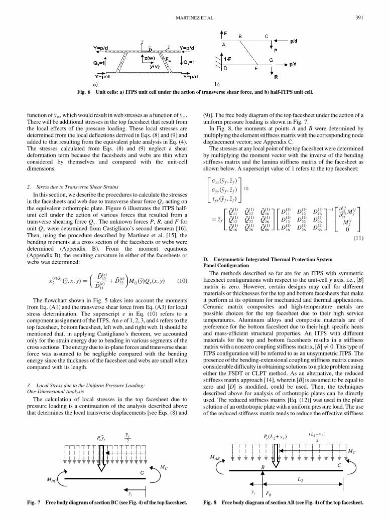
function of �yw, whichwould result inweb stresses as a function of �yw.There will be additional stresses in the top facesheet that result fromthe local effects of the pressure loading. These local stresses aredetermined from the local deflections derived in Eqs. (8) and (9) andadded to that resulting from the equivalent plate analysis in Eq. (4).The stresses calculated from Eqs. (8) and (9) neglect a sheardeformation term because the facesheets and webs are thin whenconsidered by themselves and compared with the unit-celldimensions.
2. Stress due to Transverse Shear Strains
In this section, we describe the procedures to calculate the stressesin the facesheets and web due to transverse shear forceQy acting onthe equivalent orthotropic plate. Figure 6 illustrates the ITPS half-unit cell under the action of various forces that resulted from atransverse shearing force Qy. The unknown forces P, R, and F forunit Qy were determined from Castigliano’s second theorem [16].Then, using the procedure described by Martinez et al. [15], thebending moments at a cross section of the facesheets or webs weredetermined (Appendix B). From the moment equations(Appendix B), the resulting curvature in either of the facesheets orwebs was determined:
��e�Qy�y � �y; x; y� �
�� �D�e�12�D�e�11� �D�e�22
�Mij� �y�Qy�x; y� (10)
The flowchart shown in Fig. 5 takes into account the momentsfrom Eq. (A1) and the transverse shear force from Eq. (A3) for localstress determination. The superscript e in Eq. (10) refers to acomponent assignment of the ITPS. An e of 1, 2, 3, and 4 refers to thetop facesheet, bottom facesheet, left web, and right web. It should bementioned that, in applying Castigliano’s theorem, we accountedonly for the strain energy due to bending in various segments of thecross sections. The energy due to in-plane forces and transverse shearforce was assumed to be negligible compared with the bendingenergy since the thickness of the facesheet and webs are small whencompared with its length.
3. Local Stress due to the Uniform Pressure Loading:
One-Dimensional Analysis
The calculation of local stresses in the top facesheet due topressure loading is a continuation of the analysis described abovethat determines the local transverse displacements [see Eqs. (8) and
(9)]. The free body diagram of the top facesheet under the action of auniform pressure loading is shown in Fig. 7.
In Fig. 8, the moments at points A and B were determined bymultiplying the element stiffnessmatrixwith the corresponding nodedisplacement vector; see Appendix C.
The stresses at any local point of the top facesheet were determinedby multiplying the moment vector with the inverse of the bendingstiffness matrix and the lamina stiffness matrix of the facesheet asshown below. A superscript value of 1 refers to the top facesheet:
�xx� �yf; �zf��yy� �yf; �zf��yy� �yf; �zf�
264
375 �1�
� �zf
�Q�1�11 �Q�1�12 �Q�1�16�Q�1�12 �Q�1�22 �Q�1�26�Q�1�16
�Q�1�26�Q�1�66
24
35 D�1�11 D�1�12 D�1�16
D�1�12 D�1�22 D�1�26D�1�16 D�1�26 D�1�66
24
35�1 D
�1�12
D�1�22
Mij�y
Mij�y
0
264
375
(11)
D. Unsymmetric Integrated Thermal Protection System
Panel Configuration
The methods described so far are for an ITPS with symmetricfacesheet configurations with respect to the unit-cell y axis, i.e., �B�matrix is zero. However, certain designs may call for differentmaterials or thicknesses for the top and bottom facesheets that makeit perform at its optimum for mechanical and thermal applications.Ceramic matrix composites and high-temperature metals arepossible choices for the top facesheet due to their high servicetemperatures. Aluminum alloys and composite materials are ofpreference for the bottom facesheet due to their high specific heatsand mass-efficient structural properties. An ITPS with differentmaterials for the top and bottom facesheets results in a stiffnessmatrixwith a nonzero coupling stiffnessmatrix, �B� ≠ 0. This type ofITPS configuration will be referred to as an unsymmetric ITPS. Thepresence of the bending-extensional coupling stiffness matrix causesconsiderable difficulty in obtaining solutions to a plate problemusingeither the FSDT or CLPT method. As an alternative, the reducedstiffness matrix approach [14], wherein �B� is assumed to be equal tozero and �D� is modified, could be used. Then, the techniquesdescribed above for analysis of orthotropic plates can be directlyused. The reduced stiffness matrix [Eq. (12)] was used in the platesolution of an orthotropic platewith a uniform pressure load. The useof the reduced stiffness matrix tends to reduce the effective stiffness
Fig. 6 Unit cells: a) ITPS unit cell under the action of transverse shear force, and b) half-ITPS unit cell.
CMBC
MC
2fy
fo yP
fy
Fig. 7 Free body diagram of section BC (see Fig. 4) of the top facesheet.
L2
B C
MAB
MC
FBfy
)( 2 fo yLP +2
)( 2 fyL +
Fig. 8 Free body diagram of section AB (see Fig. 4) of the top facesheet.
MARTINEZ ETAL. 391

of the plate, which results in increased bending deflections whilebuckling loads are decreased when compared with equivalentsymmetric orthotropic plates. The corresponding error in the out-of-plane plate displacement and local stresses was investigated andcompared with the FE results. The reduced bending stiffness matrix�D�� is given by [14]:
�D�� � �D� � �B��A��1�B� (12)
E. Thermal Stress Moment Resultants
The ITPS panel is exposed to extreme reentry temperatures thatresult in various temperature distributions through the ITPSthickness as a function of reentry time (transient heat transfer) [17].The temperature distribution causes the ITPS to deform due to theresulting thermal force and moments that were determined byMartinez et. al [18]. An analytical solution was derived to predict thethermal deflection of the ITPS panel when subjected to a through-the-thickness temperature distribution. A 2-D plate analysis wasneeded to determine the response of the ITPS when it was subjectedto thermal moments. Consider a rectangular plate simply supportedalong the nonloaded edges and bent by moments distributed alongthe edges x� �0; a� (Fig. 9).
The distributed moment in Fig. 9 is equal to the previouslycalculated thermal moment fromMartinez et al. [18]. Typical rangesof L=h for the ITPS will be from 10 to 20, which result innonnegligible shear effects. AnFSDTapproachwas implemented forthe deflection solution of the ITPS plate. The boundary conditions forthe thermal plate problem are as follows:
w� 0; x � 0 y� �0; b� w� 0; y � 0
x� �0; a� MTx ��D11 x;x x� �0; a� (13)
The deflections and rotations are assumed such that they satisfy alldisplacement boundary conditions along the edges y� 0 and y� b:
w�x; y� �XNn�1
An�x� sinn�y
b x�x; y� �
XNn�1
Bn�x� sinn�y
b
y�x; y� �XNn�1
Cn�x� cosn�y
b(14)
The deflection and curvature solutions of the plate are taken in theform of a series where An�x�, Bn�x�, and Cn�x� are all unknownfunctions of x only. It was assumed that the two unloaded edges aresimply supported; hence, each term of the series satisfies theboundary conditions w� 0 and x � 0 on these two sides. Itremains to determine An�x�, Bn�x�, and Cn�x� in such a form tosatisfy the boundary conditions on the sides x� 0 and x� a, and theequation of equilibrium [Eq. (A1)]. Taking the assumed deflectionand rotations in the form of a series and substituting them into theequilibrium equations results in three ordinary differential equations[Eq. (D1)].
We assume solutions to be of the form of an exponential seriesfunction; see Eq. (D2). Substituting the assumed solution fromEq. (D2) in the differential equations [Eq. (D1)] yields a set ofhomogeneous linear equations for the unknown coefficients,, and� as shown below:
det
�D11�2�D66�
2�A55 �D12�D66��� A55�
�D12�D66��� D66�2�D22�
2�A44 �A44�
A55� �A44� A55�2�A44�
2
264
375
8<:
�
9=;�
8<:0
0
0
9=; (15)
The lambdas were solved by setting the determinant of thecoefficient matrix to zero. The solution to Eq. (15) yielded sixsolutions ��; –�6�. The six roots yielded six terms in Eq. (D2), whichresulted in three equations with six unknowns per equation[Eqs. (D3–D5)]. Eighteen unknown constants resulted from theequations in Appendix D, which were not possible to solvewith onlysix boundary conditions. However, a relation was made between all18 constants (see Appendix D), which reduced the number ofindependent constants from 18 to 6. A unique solution to eachunknown constant was now available because of the equal number ofunknown constants and boundary conditions.
The moment distribution along the edges of the plate wasrepresented by the Fourier sine series as
Mx �XNn�1
Mn sinn�x
a(16)
For the case of a uniform distribution of the bending moments, thetermMn was represented asMn � 4MT
x =n�. A system of six linearequations was obtained by substituting Eq. (D2) into Eq. (14) andEq. (14) into Eq. (13):
8>>>>><>>>>>:
123456
9>>>>>=>>>>>;�
1 1 1 1 1 1
e�1b e�2b e�3b e�4b e�5b e�6b
�C1�C2
�C3�C4
�C5�C6
�C1e�1b �C2e
�2b �C3e�3b �C4e
�4b �C5e�5b �C6e
�6b
�D22�D1�1 �D22
�D2�2 �D22�D1�3 �D22
�D1�4 �D22�D1�5 �D22
�D1�6�D22
�D1�1e�1b �D22
�D1�1e�1b �D22
�D1�1e�1b �D22
�D1�1e�1b �D22
�D1�1e�1b �D22
�D1�1e�1b
26666664
37777775
�18>>>>>><>>>>>>:
0
0
0
04MT
y
m�4MT
y
m�
9>>>>>>=>>>>>>;
(17)
By solving the set of six linear equations, the assumed deflectionequations [Eq. (15)]were solved. Equations (D6) and (D7)were usedto obtain the solutions to the plate rotation in the x and y directions.The same procedure was applicable for uniformly distributed
TxM
x
L
ay
h
Fig. 9 ITPS orthotropic plate subjected to uniformly distributed
thermal end moments.
392 MARTINEZ ETAL.

bendingmoments along the y axis. In the case of simultaneous actionof couples along the entire boundary of the ITPS plate, the deflectionsand moments can be obtained by suitable superposition of the resultsobtained from the detailed discussion.
III. Results
A. Integrated Thermal Protection System Out-of-Plane
Displacement: Pressure Load
For verification of the accuracy in prediction of the deflection andstress results of an ITPS sandwich panel under the action of a uniformpressure loading, an ITPS panel with the following dimensions wasanalyzed:p� 50 mm,d� 100 mm, tTF � 1:5 mm, tBF � 1:5 mm,tw � 1:5 mm, �� 75,a� 1 m, andb� 1 m. An Inconel 617 alloywas used as an example to verify the analytical models for deter-mining local stresses in the ITPS sandwich panel (E� 202 GPa,�� 0:287). A 10-unit-cell ITPS sandwich panel wasmodeled for theanalysis (Fig. 10a). Because of symmetry of the ITPS panel, only aquarter of the plate was modeled. A 3-D FE analysis was conductedon the ITPS plate using the commercial ABAQUSTM version 6.4 FEprogram. Eight node shell elements were used to model thefacesheets and webs of the unit cell. The shell elements have thecapability to include multiple layers of different material propertiesand thicknesses that are needed to model a laminate. Three inte-gration points were used through the thickness of the shell elements.The FEM model consisted of 15,048 nodes and 5100 elements(Fig. 10b). The ITPS panel was subjected to a uniform pressureloading of 68,947 Pa (10 psi), and symmetric boundary conditionswere imposed at the edges of the ITPS plate. The bottom facesheethad an out-of-plane displacement constraint w�0; y��w�x; 0� � 0, while the top facesheet only had a rotation constraintin all three directions along x� 0 and y� 0 (Fig. 11). The FEmodelwas constrained with the appropriate boundary conditions fromEq. (2) and appropriate symmetric boundary conditions. The y-symmetric boundary conditions are
v�x; b=2� � Rx�x; b=2� � Rz�x; b=2� � 0
and the x-symmetric boundary conditions are
u�a=2; 0� � Rx�a=2; 0� � Rz�a=2; 0� � 0
TheFEMout-of-plane displacements of the ITPS panel at x� a=2were extracted and compared with the results obtained fromEqs. (4a), (8), and (9). The homogenized ITPS 2-D plate can
potentially have an unlimited number of fictitious unit cellsdepending on what x and y points are chosen. Since the FEM ITPSmodel contained 10 unit cells, for comparison, the homogenizedITPS 2-D plate was divided into a 10 10 grid. The accuracy wasverified through FE results and a convergence study. Each inter-section of the grid lines corresponded to an analytical ITPS unit cellthat corresponded to the center location of the FEM unit cell. Thecurvatures in the x and y directions at each analytical grid intersectionwere assumed to be constant for the entire unit cell; however, thecurvatures in the x and y directions from the 3-D FEM results werenot constantwithin each unit cell. The curvatures varied through eachunit cell. This stress gradient effect could not be captured by theanalytical homogenized plate model. The FEM out-of-planedisplacement contour of the ITPS is illustrated in Fig. 12. The FEMout-of-plane displacement results at x� a=2 were compared with
Fig. 10 FE a) model and b) mesh.
Fig. 11 FE boundary conditions for the ITPS plate.
Fig. 12 ITPS out-of-plane deformation.
0 0.05 0.1 0.15 0.2 0.25 0.3 0.35 0.4 0.45 0.5-1
-0.8
-0.6
-0.4
-0.2
0x 10-8
Length Along x=a/2 (m)
Out
-of-
Pla
ne
Dis
plac
emen
t (m
m/P
o)
FSDTCLPTFEM
0 0.05 0.1 0.15 0.2 0.25 0.3 0.35 0.4 0.45 0.5-8
-6
-4
-2
0
2x 10⁻⁹
Length Along x=a/2 (m)
Out
-of-
Pla
ne D
ispl
acem
ent (
mm
/Po)
FSDTFEMCLPT
Fig. 13 Out-of-plane displacement comparison between FEM and
analytical solution of the top and bottom facesheets.
0 0.1 0.2 0.3 0.4 0.5-1
-0.5
0 x 10-5
Length Along x = a / 2 (m)
0 0.1 0.2 0.3 0.4 0.5Length Along x = a / 2 (m)
Out
-of-
Pla
ne
Dis
plac
emen
t (m
m/P
o)
-8
-6
-4
-2
0x 10-6
Out
-of-
Pla
ne
Dis
plac
emen
t (m
m/P
o)
FEMAnalytical
FEMAnalytical
Fig. 14 Out-of-plane displacement comparison between FEM and
analytical solution of the top and bottom facesheets for an unsymmetric
ITPS.
MARTINEZ ETAL. 393

the analytical results (Fig. 13). As seen in Fig. 13, the analytical out-of-plane displacement results are within a 1–2% difference from theFEM results. There was greater percentage difference near theboundary of the ITPS because the boundary conditions createdlocalized effects that were not captured by the FSDTmethod and the1-D beam analysis. At the center of the ITPS plate, the structure actedmore like the homogenized 2-D plate because it was farther awayfrom the boundary. The superposition of the displacement resultsobtained from the FSDTmethod and the 1-D beam analysis resultedin a less than 5% difference and an accurate representation of the topfacesheet deflection response when subjected to a uniform pressureload. The bottom facesheet FE displacement results agreed well withthe displacement results obtained from the FSDT method. Thebottom facesheet deflection acted more like a 2-D plate because ofthe absence of local effects from the uniform pressure loading.
To verify the applicability of present methods to unsymmetricITPS, an ITPSwith a different bottom facesheet was considered. Thebottom facesheet was assumed to be of an aluminum alloy (E�72:519 GPa, �12 � 0:30). An ITPS panel with the same dimensionsas mentioned above was modeled and analyzed for investigation ofthe error in using the reduced stiffnessmatrix in the FSDTmethod foran unsymmetric ITPS panel. The FEM local stresses were extractedat x� a=2 and compared with the analytical stresses that resultedfrom the FSDT method by use of the reduced stiffness matrix. FromFig. 14, it can be noted that the plate displacement results were notaffected by using the reduced stiffness matrix in the FSDT plateanalysis. The largest difference between the FEM and analyticalresults was less than 5%.
B. Integrated Thermal Protection System Out-of-Plane
Displacement: Temperature Distribution
From the results obtained by Martinez [19] on the analysis of aplate under the action of thermal edge moments, confidence wasgained with the analytical procedure for a plate solution of anorthotropic thick plate under the action of uniformly distributed edgemoments. The next step was to apply that approach to analyticallypredict the out-of-plane displacement of an ITPS under the action ofthermal moments from an applied temperature distribution. Thetemperature distribution that was considered for the analysis was atthe 450 s reentry time of a space-shuttle-type vehicle, as described in[19] (Fig. 15). The ITPS was composed of Inconel 617, and theresulting thermal moments for Inconel 617 are calculated andcompared with the FE verification procedure discussed by Martinez[19]. The greatest percentage difference between the analytical andFEM comparison was less than 7% for MT
x . The thermal momentresults (Table 1) were used to determine the analytical out-of-planedisplacement of the ITPS panel. Table 1 consists of two moments.The aforementioned thermal plate analysis with edge moments onthe x and y axes can be used through suitable superposition (seeFig. 16).
The same ITPS panel that was modeled for the pressure loadexample was used for the temperature distribution example, exceptfor this case, the thickness of the faces and webs was increased from1.5mm (0.059 in.) to 2.0mm (0.07874 in.). The number of nodes andelements remained the same, as well as the boundary conditions. The450 s temperature distribution was included in the FEM input file,and the out-of-plane displacement of the ITPS was extracted atx� a=2 after analysis. There was no need to do any local out-of-plane displacement problem for this case because the temperatures ofthe top and bottom facesheetswere considered to be constant becauseof the thin faces when compared with the ITPS thickness. Therefore,the faces were only under the action of a thermal expansion.
The out-of-plane displacement FEM result of the ITPS panelunder the action of the fourth-order temperature distribution is shownin Fig. 16 alongwith the CLPT [19] and FSDTanalytical results. TheFSDT method for predicting out-of-plane displacement for an ITPSunder the action of uniformly distributed edge moments does notpredict accurate results for this particular ITPS panel. The FSDTmethod overpredicts the actual FE displacement by 50%, and theCLPT [20] method underpredicts the actual FE displacement by
-1
0
1
0 200 400 600 800Temperature (K)
No
rmal
ized
C
ore
Th
ickn
ess
450 s
Fig. 15 ITPS temperature distribution at 450 s reentry time.
Table 1 Thermal moments of Inconel 617 under
the 450 s reentry temperature distribution
Stiffness Mx, Nm=m My, Nm=m
Analytical 1:20E� 05 8:84E� 04FE 1:12E� 05 9:07E� 04% diff. 7.1 2.5
0
2
4
6
8
0 0.1 0.2 0.3 0.4 0.5Length Along x = a / 2 (m)
ITP
S O
ut-o
f-P
lane
D
ispl
acem
ent (
mm
)
CLPT
FSDT
TFS-FEM
BFS-FEM
a) b)
Fig. 16 ITPS a) out-of-plane thermal displacement and b) thermal displacement contour (TFS denotes top facesheet; BFS denotes bottom facesheet).
Table 2 Boundary conditions of the ITPS panel
Top facerotation
Top facedisplacement
Bottomface
rotation
Bottomface
displacement
Boundarycondition 1
X X X
Boundarycondition 2
X X
Boundarycondition 3
X X
394 MARTINEZ ETAL.

20%. The edge boundary conditions of the top and bottom facesheetsof the FEM model were modified in hopes of obtaining a goodcomparison between the FEM and analytical results. The set ofboundary conditions are listed in Table 2. An “X” represents aconstrained condition.
The ITPS out-of-plane displacement results for all differentboundary conditions are shown in Fig. 17 and compared with theCLPT and FSDT results. As seen from Fig. 17, the boundary con-dition does not affect the center plate out-of-plane displacement. Thedifferent boundary conditions had an effect on the out-of-planedisplacements that were near the edge boundary. The differentboundary conditions cause different boundary effects that affect theITPS out-of-plane displacement that cannot be captured by the FSDTor CLPTmethods. The change in boundary condition did not lead toa better comparison between the FEM and analytical results.
The thermal moments that resulted from the fourth-ordertemperature distribution caused the ITPS panel to bend due tothermal stresses. Since the ITPS plate had a low L=h value, thethermal moments acted on a short edge length of the ITPS, whichintroduced other local boundary effects into the results. These localITPS plate effects that resulted from the thermal moments were notfully captured by the FSDTand CLPTmethods when the plate had alowL=h ratio. TheL=h ratio of the ITPSwas increased to investigatewhat L=h ratio of an ITPS will result in a less than a 5% predictionerror of the FEM and analytical out-of-plane thermal displacementresults. The L=h ratio in the FEM model was increased by addingmore unit cells to the ITPS plate while keeping the ITPS thicknessconstant. For ITPS plates with largeL=h ratios, the thermal momentsnow acted on a long edge length, and all the local ITPS boundaryeffects were minimized. The ITPS panel was able to bend as a plate,and the bending behavior was captured by the FSDT that wasoutlined above. The resulting maximum out-of-plane displacementwas extracted from the FEMoutput after analysis and compared withthe maximum analytical plate displacement for various L=h ratios.The percentage error decreased from 50% for low L=h ratios to 2%for highL=h ratios (Fig. 18). The analytical and FEM results were ingood agreement for that particular L=h ratio, which resulted in a lessthan 5% prediction error of the ITPS out-of-plane displacement froma fourth-order temperature distribution (see Fig. 19). The FEM andanalytical stress results were plotted at x� a=2 for an ITPS panelwith an L=h� 18 (Figs. 20 and 21).
C. Integrated Thermal Protection System Local Stress
The FEM local stresses in the x and y directions were extractedfrom the FEM output after analysis at x� a=2. The analytical topfacesheet stresses were computed by superimposing the stressesresults from Fig. 5 and Eq. (17). The bottom facesheet and webstresses were computed from Fig. 5. All stress results were computedat �zf or w ��t=2, which was the bottom surface of each component.Similar to the out-of-plane displacement results, the percentagedifference between the FEM and analytical results was greater at theboundary of the ITPS; see Figs. 20–22. The percentage differencenear the boundary of the ITPS was 9%. The percentage difference
0
1
2
3
4
5
6
7
0 0.1 0.2 0.3 0.4 0.5
Length Along x = a / 2 (m)
ITP
S O
ut-o
f-P
lane
D
ispl
acem
ent (
mm
)TF1CLPTBF1TF2BF2TF3BF3FSDT
Fig. 17 ITPS out-of-plane displacement due to a fourth-ordertemperature distribution for various edge boundary conditions.
0
5
10
15
20
5 10 15 20
Length / Height (L / h)
ITP
S C
ente
r P
anel
D
ispl
acem
ent (
mm
)
0
10
20
30
40
50
60
70
Per
cent
age
Diff
eren
ce %
FEMFSDT% difference
Fig. 18 ITPS center panel displacement for various L=h values.
0 0.1 0.2 0.3 0.4 0.5-10
-5
0
5x 10⁻⁴
Length at x = a / 2 (m)
0 0.1 0.2 0.3 0.4 0.5Length at x = a / 2 (m)
σ xx
(MP
a/P
o)σ y
y (M
Pa/
Po)
-2
0
2x 10⁻³
FEMAnalytical
FEMAnalytical
Fig. 20 Top facesheet stress in the x and y directions of the ITPS panel.
0 0.1 0.2 0.3 0.4 0.5-1
0
1x 10⁻³
Length Along x = a / 2 (m)
0 0.1 0.2 0.3 0.4 0.5Length Along x = a / 2 (m)
σ xx
(MP
a/P
o)σ y
y (M
Pa/
Po)
-4
-2
0
2x 10⁻³
FEMAnalytical
FEMAnalytical
Fig. 21 Bottom facesheet stress in the x and y directions of the ITPS
panel.
0
5
10
15
0 0.2 0.4 0.6 0.8
Length Along x = a / 2 (m)
ITP
S O
ut-o
f-P
lane
Dis
plac
emen
t (m
m)
BF-FEMTF-FEMFSDT
Fig. 19 ITPS out-of-plane displacement due to a temperature
distribution for an ITPS with L=h� 18.
MARTINEZ ETAL. 395

was less than 2% for stress results near the center of the ITPS plate.The percentage difference for the web stress in the x direction wasless than 1% when compared with the FEM results. The percentagedifference for the web stresses in the y direction was less than 3% atthe center of the plate and greater than 5% near the boundary of theITPS panel. The analytical local stress of the right web in the �ywdirection was different than the FEM results because, near theboundary of the ITPS, therewas a large change in curvature due to thelocal boundary effect that was not captured by the analytical model.The curvaturewas changing through the length of the unit cell while,in the analytical model, the curvature was kept constant. The localstress prediction gets better when the local stresses are compared atthe center of the plate. There are less boundary effects, and thecurvature can be assumed constant for a unit cell.
For investigation of the penalty of using the reduced stiffnessmatrix in the FSDT method for an unsymmetric ITPS panel, anunsymmetric panel with the same dimensions as mentioned abovewasmodeled and analyzed. The difference in this newmodelwas thatthe top facesheet and webs were composed of Inconel 617, and thebottom facesheet was composed of an aluminum alloy (E�72:519 GPa, �12 � 0:3). The FEM local stresses were extracted atx� a=2 and compared with the analytical stresses that resulted fromthe FSDT method by use of the reduced stiffness matrix. Thecomparison between the FE results and the stress results obtainedfrom the FSDTmethod are illustrated in Figs. 22 and 23. The resultsindicated that there was a 20% difference between the analytical andFE results in the top facesheet when using the reduced stiffnessmatrix. The use of the reduced stiffness matrix in the FSDT methoddid not have any effect on the bottom facesheet and web stresseswhen compared with the FEM results. The difference was muchmore noticeable in the top facesheet because of the local effects thatresulted from the uniform pressure load.
IV. Conclusions
A2-D plate solution for determining out-of-plane displacement ofan orthotropic thick platewas established and verifiedwith FEM for auniform pressure load and uniform thermal edge moments.Additional local facesheet deformations and stress were super-imposed with the 2-D plate results to capture the local effects of thedistributed pressure load on the facesheets. Kirchhoff hypotheses andEuler–Bernoulli plate equationswere used for the local displacementand stress analysis of the facesheets and webs. The symmetric andunsymmetric plates resulted in a less than 5% prediction error in theplate’s out-of-plane displacements when compared with the FEM.The plate solution provided less than 5% prediction error results forITPS panels with L=h ratios greater than 18. An ITPS panel with alow L=h introduced local boundary effects that contributed to thepanel’s out-of-plane displacement. A 1-D beam analysis was done onthe top facesheet to account for the local bending of the top facesheetdue to its thin thickness. The local boundary effects that introducedlocal displacements and stresses were not fully captured with eitherthe FSDT method or the CLPT method.
Appendix A: Plate Equilibrium Equationsand Constitutive Relations
The plate equilibrium equations are
@Mx
@x�@Mxy
@y�Qx � 0
@Mxy
@x�@My
@y�Qy � 0
@Qx
@x�@Qy
@y� Pz � 0 (A1)
The plate constitutive relations are( Mx
My
Mxy
)�
D11 D12 0
D12 D22 0
0 0 D66
24
35( x;x
y;y x;y � y;x
)(A2)
�Qy
Qx
�� k C44 0
0 C55
� �� y �w;y x �w;x
�(A3)
Appendix B: Moments in the Half-Unit Cell
In this Appendix, we provide the expressions for bendingmoments in various parts of the unit cell due to unit transverse force[see Eq. (10)]. The detailed derivations can be found in [20]:
MAB� �y� � F �y 0 � �y � f (B1)
MBC� �y� � P �y 0 � �y � p � f (B2)
MDE� �y� � �1 � F� �y � �P� R�p � Jd 0 � �y � p � f (B3)
MEG� �y� � R �y 0 � �y � f (B4)
MBE� �y� � F�f� �y cos �� � P�p � f � �y cos �� �H �y sin �
0 � �y � s(B5)
Appendix C: Local Bending Stress in Facesheetsdue to a Uniform Pressure Loading
The moments in the equations shown below are the result of theuniform pressure loading acting on the top facesheet. The momentswere obtained from a 1-DFE analysis. Themoments weremultiplied
0 0.1 0.2 0.3 0.4 0.5-10
-5
0
5x 10⁻⁴
Length Along x = a / 2 (m)
0 0.1 0.2 0.3 0.4 0.5Length Along x = a / 2 (m)
σ xx
(MP
a/P
o)σ y
y (M
Pa/
Po)
-3
-2
-1
0
1x 10⁻³
FEMAnalytical
FEMAnalytical
Fig. 23 Bottom facesheet stress in the x and y directions of an
unsymmetric ITPS panel.
Fig. 22 Top facesheet stress in the x and y directions of an unsymmetric
ITPS panel.
396 MARTINEZ ETAL.
with the bending stiffness matrix of the facesheet to obtain facesheetstress:
MC �EI
L32
�2L22�B � 6L2vB� (C1)
MA �EI
L31
�6L1vA � 2L21�B� (C2)
The bending moment distribution in the top facesheet consists oftwo equations:
MBC�y � �y� �MC � Po
�y2
20 � �y � p � f (C3)
MAB�y � �y� � FB �y�MC � Po
�L2 � �y�22
0 � �y � f (C4)
Appendix D: Edge Moments
In this section, the assumed solutions to the plate deflection withedgemoments are provided. A relationship is alsomade to reduce thenumber of unknown constants from 18 to 6.
Ordinary differential equations to a 2-D plate with edge moments:
D11B00n�x� � �D66�
2 � C55�Bn�x� � �D12 �D66��C0n�x�� C55A
0n�x� � 0 (D1a)
D66C00n�x� � �D22�
2 � C44�Cn�x� � �D12 �D66��B0n�x�� C44�An�x� � 0 (D1b)
C55A00n�x� � C44�
2An�x� � C55B0n�x� � C44�Cn�x� � 0 (D1c)
An�x� �XNi�1
ie�ix (D2a)
Bn�x� �XNi�1
ie�ix (D2b)
Cn�x� �XNi�1
�ie�ix (D2c)
An�x� � 1e�1x � 2e�2x � 3e�3x � 4e�4x � 5e�5x � 6e�6x(D3)
Bn�x� � 1e�1x � 2e
�2x � 3e�3x � 4e
�4x � 5e�5x � 6e
�6x
(D4)
Cn�x� � �1e�1x � �2e�2x � �3e�3x � �4e�4x � �5e�5x � �6e�6x(D5)
i � i�ki12k
i23 � ki22ki13
ki22ki11 � ki12ki21
�� �Cii (D6)
�i � i�ki13k
i21 � ki23ki11
ki22ki11 � ki12ki21
�� �Dii (D7)
ki11 ��D11�2i �D66�
2 � C55 (D8)
ki22 �D66�2i �D22�
2 � C44 (D9)
ki21 � ki12 � �D12 �D66��i� (D10)
ki23 ��C44� (D11)
ki13 � C55�i (D12)
Acknowledgments
This research is sponsored by a NASA grant under theConstellation University Institutes Project. The program manager isClaudia Mayer at NASA John H. Glenn Research Center at LewisField.
References
[1] Zhu, H., “Design ofMetallic Foams as Insulation in Thermal ProtectionSystems,” Ph.D. Dissertation, Univ. of Florida, Gainesville, FL, 2004.
[2] Blosser, M. L., “Advanced Metallic Thermal Protection Systems forReusable Launch Vehicles,” Ph.D. Dissertation, Univ. of Virginia,Charlottesville, VA, 2000.
[3] Martinez, O., Sankar, B. V., Haftka, R., Blosser, M., and Bapanapalli,S. K., “Micromechanical Analysis of a Composite Corrugated-CoreSandwich Panel for Integral Thermal Protection Systems,” AIAA
Journal, Vol. 45, No. 9, 2007, pp. 2323–2336.doi:10.2514/1.26779
[4] Martinez, O., Sharma, A., Sankar, B. V., Haftka, R., and Blosser, M. L.,“Thermal Response Analysis of an Integrated Thermal ProtectionSystem for Future Space Vehicles,”AIAA Journal, Vol. 48, No. 1, 2010,pp. 119–128.doi:10.2514/1.40678
[5] Fung, T. C., Tan, K. H., and Lok, T. S., “Analysis of C-Core SandwichPlate Decking,” Proceedings of the 3rd International Offshore and
Polar Engineering Conference, Mountain View, CA, Vol. 4, 1993,pp. 244–249.
[6] Fung, T. C., Tan, K. H., and Lok, T. S., “Elastic Constants for Z-CoreSandwich Panels,” Journal of Structural Engineering, Vol. 120, No. 10,1994, pp. 3046–3065.doi:10.1061/(ASCE)0733-9445(1994)120:10(3046)
[7] Libove, C., and Hubka, R. E., “Elastic Constants for Corrugated CoreSandwich Plates,” NACATN-2289, 1951.
[8] Lok, T. S., Cheng,Q., andHeng, L., “Equivalent Stiffness Parameters ofTruss-Core Sandwich Panel,” Proceedings of the Ninth International
Offshore and Polar Engineering Conference, Vol. 4, International Soc.of Offshore and Polar Engineers, Brest, France, 1999, pp. 292–298.
[9] Valdevit, L., Hutchinson, J. W., and Evans, A. G., “StructurallyOptimized Sandwich Panels with Prismatic Cores,” International
Journal of Solids and Structures, Vol. 41, May 2004, pp. 5105–5124.doi:10.1016/j.ijsolstr.2004.04.027
[10] Lok, T. S., and Cheng, Q., “Elastic Stiffness Properties and Behavior ofTruss-Core Sandwich Panel,” Journal of Structural Engineering,Vol. 126, No. 5, May 2000, pp. 552–559.doi:10.1061/(ASCE)0733-9445(2000)126:5(552)
[11] Fung, T. C., Tan, K.H., and Lok, T. S., “Shear Stiffness DQy for C-CoreSandwich Panels,” Journal of Structural Engineering, Vol. 122, No. 8,1996, pp. 958–966.doi:10.1061/(ASCE)0733-9445(1996)122:8(958)
[12] Libove, C., and Batdorf, S. B., “AGeneral Small Deflection Theory forFlat Sandwich Plates,” NACATN-1526, 1948.
[13] Whitney, M., Structural Analysis of Laminated Anisotropic Plates,Technomic, Lancaster, PA, 1987, Chaps. 7–9.
MARTINEZ ETAL. 397

[14] Reddy, J. N., Mechanics of Laminated Composite Plates Theory and
Analysis, CRC Press, Boca Raton, 1997, Chaps. 5–6.[15] Martinez, O., Bapanapalli, S., Sankar, B. V., Haftka, R., and Blosser,
M., “Micromechanical Analysis of a Composite Truss Core SandwichPanel for Integral Thermal Protection Systems,” 47th AIAA/ASME/ASCE/AHS/ASC Structures, Structural Dynamics, and MaterialsConference, Newport, RI, AIAA Paper 2006-1876, May 2006.
[16] Sankar, B. V., and Kim, N. H., Introduction to Finite Element Analysisand Design, Wiley, NY, 2009, Chaps. 3–4.
[17] Bapanapalli, S. K., Martinez, O., Sankar, B. V., Haftka, R. T., andBlosser, M. L., “Analysis and Design of Corrugated-Core SandwichPanels for Thermal Protection Systems of Space Vehicles,” 47th AIAA/ASME/ASCE/AHS/ASC Structures, Structural Dynamics, andMaterials Conference, Newport, RI, AIAA Paper 2006-1942,
May 2006.[18] Martinez, O., Sankar, B. V., and Haftka, R. T., “Thermal Response
Analysis of an Integral Thermal Protection System for Future SpaceVehicles,” ASME International Mechanical Engineering Congress and
Exposition, Chicago, IL, American Soc. of Mechanical EngineersPaper 2006-14522, Fairfield, NJ, Nov. 2006.
[19] Martinez, O., “Micromechanical Analysis and Design of an IntegratedThermal Protection System for Future Space Vehicles,” Ph.D.Dissertation, Univ. of Florida, Gainesville, FL, 2007.
[20] Timoshenko, S., and Woinowsky-Kreiger, S., Theory of Plates and
Shells, Timoshenko, McGraw–Hill, New York, 1959, pp. 180–185.
R. OhayonAssociate Editor
398 MARTINEZ ETAL.