two-ports and power gain - university of california,...
TRANSCRIPT
Berkeley
Two-Ports and Power Gain
Prof. Ali M. Niknejad
U.C. BerkeleyCopyright c© 2016 by Ali M. Niknejad
September 28, 2017
1 / 26

Power Gain
2 / 26

Power Gain
+vs
!
YS
YL
!y11 y12
y21 y22
"
Pin PL
Pav,s Pav,l
We can define power gain in many different ways. The powergain Gp is defined as follows
Gp =PL
Pin= f (YL,Yij) 6= f (YS)
We note that this power gain is a function of the loadadmittance YL and the two-port parameters Yij .
3 / 26

Power Gain (cont)
The available power gain is defined as follows
Ga =Pav ,L
Pav ,S= f (YS ,Yij) 6= f (YL)
The available power from the two-port is denoted Pav ,L
whereas the power available from the source is Pav ,S .
Finally, the transducer gain is defined by
GT =PL
Pav ,S= f (YL,YS ,Yij)
This is a measure of the efficacy of the two-port as itcompares the power at the load to a simple conjugate match.
4 / 26

Derivation of Power Gain
The power gain is readily calculated from the inputadmittance and voltage gain
Pin =|V1|2
2<(Yin)
PL =|V2|2
2<(YL)
Gp =
∣∣∣∣V2
V1
∣∣∣∣2 <(YL)
<(Yin)
Gp =|Y21|2
|YL + Y22|2<(YL)
<(Yin)
5 / 26

Derivation of Available Gain
YSIS
!Y11 Y12
Y21 Y22
"YeqIeq
To derive the available power gain, consider a Nortonequivalent for the two-port where (short port 2)
Ieq = −I2 = Y21V1 =−Y21
Y11 + YSIS
The Norton equivalent admittance is simply the outputadmittance of the two-port
Yeq = Y22 −Y21Y12
Y11 + YS
6 / 26

Available Gain (cont)
The available power at the source and load are given by
Pav ,S =|IS |2
8<(YS)Pav ,L =
|Ieq|28<(Yeq)
Ga =
∣∣∣∣IeqIS
∣∣∣∣2 <(YS)
<(Yeq)
Ga =
∣∣∣∣Y21
Y11 + YS
∣∣∣∣2 <(YS)
<(Yeq)
7 / 26

Transducer Gain Derivation
The transducer gain is given by
GT =PL
Pav ,S=
12<(YL)|V2|2
|IS |28<(YS )
= 4<(YL)<(YS)
∣∣∣∣V2
IS
∣∣∣∣2
We need to find the output voltage in terms of the sourcecurrent. Using the voltage gain we have and input admittancewe have ∣∣∣∣
V2
V1
∣∣∣∣ =
∣∣∣∣Y21
YL + Y22
∣∣∣∣
IS = V1(YS + Yin)∣∣∣∣V2
IS
∣∣∣∣ =
∣∣∣∣Y21
YL + Y22
∣∣∣∣1
|YS + Yin|
8 / 26

Transducer Gain (cont)
|YS + Yin| =
∣∣∣∣YS + Y11 −Y12Y21
YL + Y22
∣∣∣∣
We can now express the output voltage as a function ofsource current as
∣∣∣∣V2
IS
∣∣∣∣2
=|Y21|2
|(YS + Y11)(YL + Y22)− Y12Y21|2
And thus the transducer gain
GT =4<(YL)<(YS)|Y21|2
|(YS + Y11)(YL + Y22)− Y12Y21|2
9 / 26

Maximum Power Gain and the Bi-Conjugate Match
10 / 26
Comparison of Power Gains
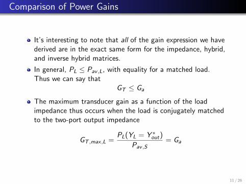
It’s interesting to note that all of the gain expression we havederived are in the exact same form for the impedance, hybrid,and inverse hybrid matrices.
In general, PL ≤ Pav ,L, with equality for a matched load.Thus we can say that
GT ≤ Ga
The maximum transducer gain as a function of the loadimpedance thus occurs when the load is conjugately matchedto the two-port output impedance
GT ,max ,L =PL(YL = Y ∗out)
Pav ,S= Ga
11 / 26

Comparison of Power Gains (cont)
Likewise, since Pin ≤ Pav ,S , again with equality when the thetwo-port is conjugately matched to the source, we have
GT ≤ Gp
The transducer gain is maximized with respect to the sourcewhen
GT ,max ,S = GT (Yin = Y ∗S ) = Gp
12 / 26

Bi-Conjugate Match
When the input and output are simultaneously conjugatelymatched, or a bi-conjugate match has been established, wefind that the transducer gain is maximized with respect to thesource and load impedance
GT ,max = Gp,max = Ga,max
This is thus the recipe for calculating the optimal source andload impedance in to maximize gain
Yin = Y11 −Y12Y21
YL + Y22= Y ∗S
Yout = Y22 −Y12Y21
YS + Y11= Y ∗L
Solution of the above four equations (real/imag) results in theoptimal YS ,opt and YL,opt .
13 / 26

Calculation of Optimal Source/Load
Another approach is to simply equate the partial derivatives ofGT with respect to the source/load admittance to find the
maximum point
∂GT
∂GS= 0
∂GT
∂BS= 0
∂GT
∂GL= 0
∂GT
∂BL= 0
Again we have four equations. But we should be smarterabout this and recall that the maximum gains are all equal.Since Ga and Gp are only a function of the source or load, wecan get away with only solving two equations.
14 / 26

Calculation of Optimal Source/Load
Working with available gain
∂Ga
∂GS= 0
∂Ga
∂BS= 0
This yields YS,opt and by setting YL = Y ∗out we can find theYL,opt .
Likewise we can also solve∂Gp
∂GL= 0
∂Gp
∂BL= 0
And now use YS ,opt = Y ∗in.
15 / 26

Optimal Power Gain Derivation
Let’s outline the procedure for the optimal power gain. We’lluse the power gain Gp and take partials with respect to theload. Let
Yjk = mjk + jnjk
YL = GL + jXL
Y12Y21 = P + jQ = Le jφ
Gp =|Y21|2D
GL
<(Y11 −
Y12Y21
YL + Y22
)= m11 −
<(Y12Y21(YL + Y22)∗)
|YL + Y22|2
D = m11|YL + Y22|2 − P(GL + m22)− Q(BL + n22)
∂Gp
∂BL= 0 = −|Y21|2GL
D2
∂D
∂BL
16 / 26

Optimal Load (cont)
Solving the above equation we arrive at the following solution
BL,opt =Q
2m11− n22
In a similar fashion, solving for the optimal load conductance
GL,opt =1
2m11
√(2m11m22 − P)2 − L2
If we substitute these values into the equation for Gp (lot’s ofalgebra ...), we arrive at
Gp,max =|Y21|2
2m11m22 − P +√
(2m11m22 − P)2 − L2
17 / 26

Final Solution
Notice that for the solution to exists, GL must be a realnumber. In other words
(2m11m22 − P)2 > L2
(2m11m22 − P) > L
K =2m11m22 − P
L> 1
This factor K plays an important role as we shall show that italso corresponds to an unconditionally stable two-port. Wecan recast all of the work up to here in terms of K
YS,opt = −j=(Y11)+Y12Y21 − 2<(Y11)<(Y22) + |Y12Y21|(K +
√K 2 − 1)
2<(Y22)
YL,opt = −j=(Y22)+Y12Y21 − 2<(Y11)<(Y22) + |Y12Y21|(K +
√K 2 − 1)
2<(Y11)
Gp,max = GT ,max = Ga,max =Y21
Y12
1
K +√K 2 − 1
18 / 26

Maximum Gain
The maximum gain is usually written in the followinginsightful form
Gmax =Y21
Y12(K −
√K 2 − 1)
For a reciprocal network, such as a passive element, Y12 = Y21
and thus the maximum gain is given by the second factor
Gr ,max = K −√K 2 − 1
Since K > 1, |Gr ,max | < 1. The reciprocal gain factor isknown as the efficiency of the reciprocal network.
The first factor, on the other hand, is a measure of thenon-reciprocity.
19 / 26

Unilateral Maximum Gain
For a unilateral network, the design for maximum gain istrivial. For a bi-conjugate match
YS = Y ∗11
YL = Y ∗22
GT ,max =|Y21|2
4m11m22
20 / 26

Stability of a Two-Port
21 / 26

Stability of a Two-Port
A two-port is unstable if the admittance of either port has anegative conductance for a passive termination on the secondport. Under such a condtion, the two-port can oscillate.Consider the input admittance
Yin = Gin + jBin = Y11 −Y12Y21
Y22 + YL
Using the following definitions
Y11 = g11 + jb11
Y22 = g22 + jb22
Y12Y21 = P + jQ = L∠φ
YL = GL + jBLNow substitute real/imag parts of the above quantities intoYin
Yin = g11 + jb11 −P + jQ
g22 + jb22 + GL + jBL
= g11 + jb11 −(P + jQ)(g22 + GL − j(b22 + BL))
(g22 + GL)2 + (b22 + BL)222 / 26

Input Conductance
Taking the real part, we have the input conductance
<(Yin) = Gin = g11 −P(g22 + GL) + Q(b22 + BL)
(g22 + GL)2 + (b22 + BL)2
=(g22 + GL)2 + (b22 + BL)2 − P
g11(g22 + GL)− Q
g11(b22 + BL)
D
Since D > 0 if g11 > 0, we can focus on the numerator. Notethat g11 > 0 is a requirement since otherwise oscillationswould occur for a short circuit at port 2.
The numerator can be factored into several positive terms
N = (g22 +GL)2 +(b22 +BL)2− P
g11(g22 +GL)− Q
g11(b22 +BL)
=
(GL +
(g22 −
P
2g11
))2
+
(BL +
(b22 −
Q
2g11
))2
−P2 + Q2
4g211
23 / 26

Input Conductance (cont)
Now note that the numerator can go negative only if the firsttwo terms are smaller than the last term. To minimize thefirst two terms, choose GL = 0 and BL = −
(b22 − Q
2g11
)
(reactive load)
Nmin =
(g22 −
P
2g11
)2
− P2 + Q2
4g211
And thus the above must remain positive, Nmin > 0, so
(g22 +
P
2g11
)2
− P2 + Q2
4g211
> 0
g11g22 >P + L
2=
L
2(1 + cosφ)
24 / 26

Linvill/Llewellyn Stability Factors
Using the above equation, we define the Linvill stability factor
L < 2g11g22 − P
C =L
2g11g22 − P< 1
The two-port is stable if 0 < C < 1.
25 / 26
Stability (cont)
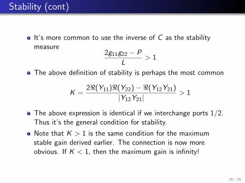
It’s more common to use the inverse of C as the stabilitymeasure
2g11g22 − P
L> 1
The above definition of stability is perhaps the most common
K =2<(Y11)<(Y22)−<(Y12Y21)
|Y12Y21|> 1
The above expression is identical if we interchange ports 1/2.Thus it’s the general condition for stability.
Note that K > 1 is the same condition for the maximumstable gain derived earlier. The connection is now moreobvious. If K < 1, then the maximum gain is infinity!
26 / 26