two sew .teiahole- ihteg-hati01...
TRANSCRIPT

Two new triangle-integration multipliers
Item Type text; Thesis-Reproduction (electronic)
Authors Hartmann, John P., 1935-
Publisher The University of Arizona.
Rights Copyright © is held by the author. Digital access to this materialis made possible by the University Libraries, University of Arizona.Further transmission, reproduction or presentation (such aspublic display or performance) of protected items is prohibitedexcept with permission of the author.
Download date 01/07/2018 04:06:53
Link to Item http://hdl.handle.net/10150/319288

TWO SEW. TEIAHOLE- IHTEG-HATI01 3EJI5IPBIEES;
' ' ' . by ■ -Jon P» Har-tmam
A Thesis Submitted to the Faculty of the' jDEPARTMEM1 . EhEOTRIGAL. ElCHlEEBlia
In.Partial Pulfillment of the Requirements . For the Degree of - -
; . 1AS1ER OF- SClEhJS ' V ^In the Graduate College
THE UNIVERSITY OF ARIZONA
I960

STATEMENT BY AUTHOR
This thesis has been submitted in partial fulfillment of requirements for an advanced degree at The University of Arizona and is deposited in The University Library to be made available to borrowers under rules of the Library.
Brief quotations from this thesis are allowable without special permission, provided that accurate acknowledgment of source is made. Requests for permission for extended quotation from or reproduction of this manuscript in whole or in part may be granted by the head of the major department or the Dean of the Graduate College when in their judgment the proposed use of the material is in the interests of scholarship. In all other instances, however, permission must be obtained from the author.
APPROVAL BY THESIS DIRECTOR This thesis has been approved on the date shown below:
______w c ft . iCirwy —_______________™ G. A. KORN
Professor of Electrical EngineeringDate
ill

C01TEOTS
CHAPTEB. I. IMTRODUCTIOM ' . ' ..’ 1=1 c Analog Multipliers and Subject of Thesis „ o <, 1
CHAPTER 11= THREE HEW TRIAHG-LE INTEGRATION MULTIPLIER CIRCUITS ,
2-le Discussion of Circuits » = = = = = = » = = = = if.2=2,, Factors 'Affecting Multiplication Accuracy" .. and Frequency Response = = , = = = = ' = = = = o = 8
. 2=3° Physical Realizability of Multipliers Basedon the Three Triangle=lntegration Multiplication Circuits » . = = » ® « = = = . = = = 9
CHAPTER III I. THE PRECISION FEEDBACK LIMITER AND HUDTIPLlER-lOc.1
The Precision:Feedback, LlBifer; 1 = = » = . = >. 103=2 o Application' of Precis ion Feedback Lliaiter ,
to Multiplier, No« 1 = ».; = = = = = = » = = = = 123=3? Perf ormance of Multiplier No = 1. = ...» :. = = = IS
CHAPTER IV o THE PRECISION DEAD= SPACE LIIilTEE AND. i ; ' m 2. : :. v";./ 'iq-lo The Precision Dead-Space Dimiter .» = „ = » » 16
. Ip-2 = Application of Precision ,Dead=Space Limiterto Multiplier; Noo 2 = . = = = » = =. = ® = = » 16
. 4'-3° Performance of Multiplier No0 2 20
CHAPTER Vo * OUTPUT.PIETERS AID TRIANGLE GENERATOR ' ■ Output Piltei’S «:T~2'<, Triangle Generator .
0 O O O O O O ■ » , ©• 'O © o o o-
o . 0 : 0. o e o o o . 9 o & o-
CHAPTER VI. • •PURTHER DEVELOPHENTS' AND’ ■'COIIPARISON WITH '■ , / OTHER ALL-ELECTRONIC MULTIPLIERS . '
O o o ©. ©6-ii.; Suggested Further Developments . ®6-2» Cpmparis on of Multipliers Ndo. • I and 2 With f Commereially Available A11=E1eetronic .:' - ; ':#uitipiierst o- . . . « ... ! - :.v.o;v „ . .p.;' . v. ■ y
BIBLIOGRAPHY „ . . . . . . . . . „ . . . . . . . « o =•
.22■ => 25 . .
c 26
. 28
ILLUSTRATIONS
2-10. Circuits For Implementing . tlie Three AmplitudeSeleetioxi i etziocts .o © © © © © © © © © © © © © © <
2-2© Voltage Waveforms For -the Three Amplitude'■ Selection Methods © © » . © © © . © © » '© ©. «;.© .3-=-la© Precision Feedback Limiter © © © © © © © » © © .
b© Conventional Series Limiter » o ©. , © © © © © © <c© Characteristics of the Two Limiters,...
Are Compare d © © ©,© © © © © © © © © © © © ©. © c3-2© Circuit of Multiplier lo©. 1 Incorporating
Precision Limiters ©; © © © © ©. © © © © © © .© © <. %-l© . Precision Dead-Space Limiter» © © ©■ «' ’©' » © » <li-2©. Circuit of Multiplier Ho<> 2 Incorporating
the Precision Dead-Space Limiter © © > © © © © <3-la© Filter Network Used With Multiplier So © 1 1. » © <
bo Filter Hetv/ork Used With Multiplier No© 2 © © © ©3-2© 3 kc Triangle Generator Circuit © © »;•'»: © © ©• ©: c
• 3© 6 © 11 © 11
© 11
o 13 © 17
o 19 . < :23. © 23 © 2%

; JbaBlog Editipll63?s^9^ and Subject of "Hiesis 0
• The function multipliers us eh with analog computers are either servo- driven potentibmeter types or all-eiectronie devices employing non-linear operations to achieve multiplication of two or more time-varying voltages o The servo m u l t i - . plier has a multiplication accuracy of better than O d per cent of full scale o.-' hut it contains el ec fro -me chani e al components which limit. its upper frequency response to below 3 to ij.0 cpso'- Al 1- elec t roni c multipliers on the other hand-.have excellent: frequency response3 out to lg000 ops for some models3; and are free from mechanical) wearg they are also the most accurate analog multipliers, availableg with static accuracies\ / better than) 0»01 per cent of full scale0 : ' " -■
; At the: present time.; the three most widely-us ed all- ..) electronic:'multipliers : are' the time-division multiplier, the ■ quarter-square diode multipliers and the triangle-integration multiplier0-: All three types are relatively complicated circuits
For a more, complete discussion of analog computer multi- ) pliers- 'refer to 5 ■ . -- -).;: ) '. ■. G-o Atf- and T0: K<s :Kotyi3 \ Electronic. Analog Computers0 2nd' Edo ■, McGraw-Hill, Book Co0 s Incog 195^7 Chapt 6=Go ho Johns0% Analog. Computer Techniques9 McGraw-Hill Book
Coo 9 Inco, 19^0g Chapt p° andT13T ~

i S S T B W
.Two . new analog multipliers, which us e the principle of triangle integration are described* Included is a discussion, of the principle of triangle' integration^ a description of the two nef''multipliers*. their - measured: .perf ormances the designs for an accurate 5 he triangle-war© generator and two’ lovr pass filters* and finally a discussion of the huproyements that can be made, in ' the two. multipliers and a :■ comparison of their cost and accuracy to comparable commercially available analog.muitipliers* ■ . ' , . . ■ :

wien elesigned to multiply with high accuracyo Some models incorporate as many as six operational; amplifiers, and the . mlnlmnm nsed yin any/ of the commercially available' Milti- 'pllefs: .is three#. - 11 would be desirable to develop an-.;-all=electronic multiplier of minimum circult complexity that;, ■: could be manufactured:at::;a ;cost" boiW'that of existing . ip eopaerQihliy : ayallahle: inuMipllersand yet have raultiplica- tion accuracy and frequency response comparable to thoseof;;existing modeis# : : i:;p: : p; ; fhis thesis describes two successful all=electronic "
:fQtir=qUadrant multipliers designed to meet the above re- . . ■ p. quirements c. Both multipliers Utilize the triangle-integration method of multiplication^ which was chosen because it can be implemented with .a minimum of circuit components0 ■SeyeralfeleOtronio; imalflpllers::fl including; at plea St...two-comp;, f mercially available raodels9 are based on this method; however all use three or more operational amplifiers 0* 3 $ 6 one ' ;of the multipliers described,in this, paper requires only 'two •operational amplifiers;' and the other uses three® In • ,
. A® layer;' and H® B®. DaviS c, n!rlangular-wave Analog ■Maltiplier®; 'EISCTMIGSS., Aug® 1956® ;
"Po Bo Pfeiffers "A Pour Quadrant Multiplier^; • IRAK'S® PGEO@;®ept 6.;;i 59:*|:..;: ; ■ ” ;p ; : : .; '1' ,a;p . '; t..- ■ ;^General Electric (Phoenix) s Advance. Bulletih• on G-E Analog.
Computing Modules 9 1959» - • ■ • , .i; , 'Co. A® Philbrick Researches^. Bostons, Masseg. Specifies-
,;tlon. Sheets .for and_.E5fl..lultiplier#®.., '

; ■■ ■ . ' ■ / 3additions both multiplier's, require an external phase-inrerting amplifier to supply push-pull input voltages* This additional : amplifier''is hdirevers usually available in the computer set .
.CHAPTER II THREE HEW TRIANGLE ■ IKTEORATIOH ■ ■ MULTIPLIER CIRCUITS ,
2‘~10 Discussion of the Circuits0 , r • -/
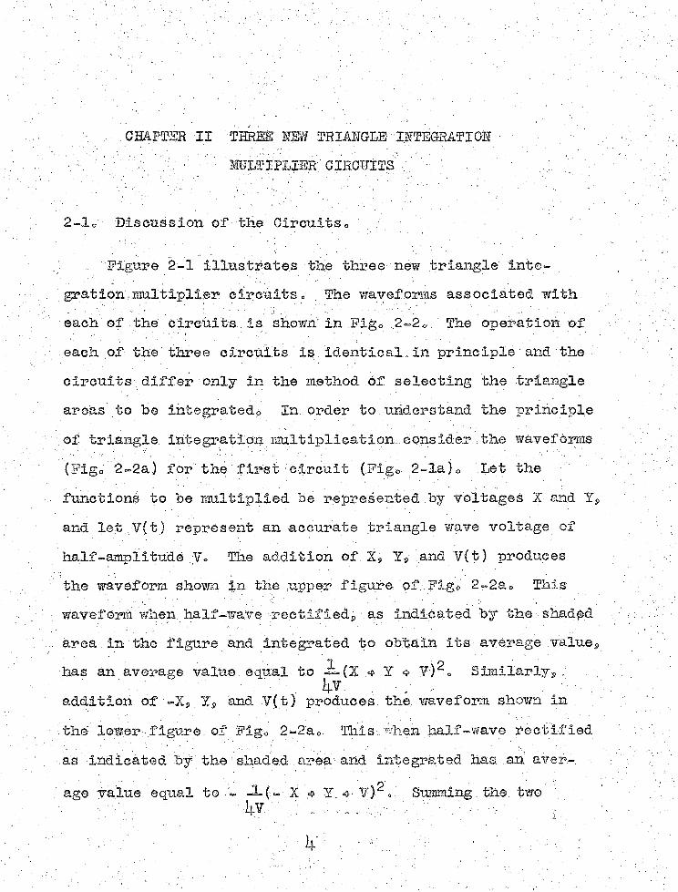
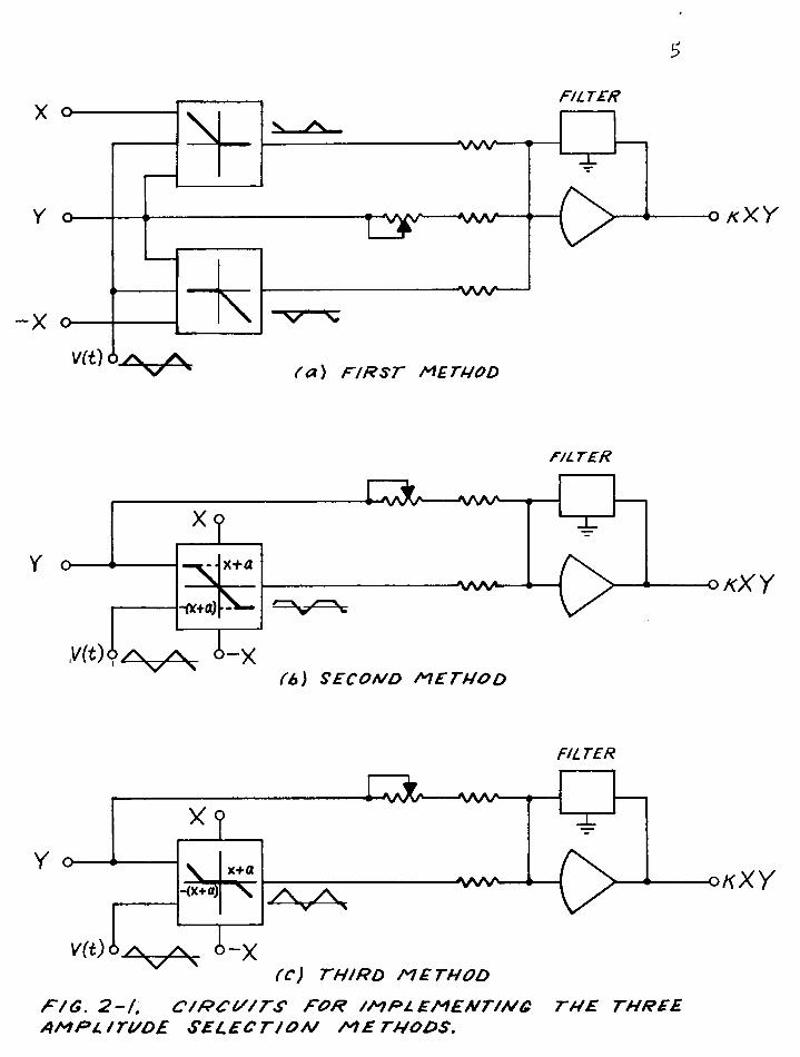
''Figure i2-l illustrates the three new triangle inte- grat ion - multiplier1 circuits , , Hie wavef orms associated with , each of the circuits is shown' in Figo 2=2, The operation of each of the three circuits Is Identical_in. principle ' and : the circuits. differ only in the method of selecting the triangle areas to be integrated^ In. order to understand, the principle of triangle,: Integration multiplication - consIder . the waveforms .
: (Figo 2-2a) for the first circuit (Fig*- 2=la)0 Let the functions to be multiplied be represented bj voltages X and Y, and let.¥(t} represent an accurate triangle wave voltage of half-amplitude Y, The addition of X, Y, and Y(t) produces the wavef orm shown, in the .upper f igure of ,Flg«: .2-2ao This waveform when: half-wave rectified;,; as indicated by the. shaded area.in the figure and integrated to obtain its average value^has an average value. equal. to. 4 Y «> V)^, Similarly5, .■
. ■ ■ . ■ ' ' ' ' .' . . # - - I '■ , :■ /addition of Y» and V(t) produces, the waveform shown inthe lower figure, of Figo 2-2a0. This., when half-wave rectifiedas indicated 'by the' shaded, area /and . Integrated has. an aver-. .age value equal to -2= ( - X 4 Y. V) = Summing ;, the. two '
5
FILTER
AAAA
~X o( a ) F I R S T M ETHOD
FILTER
Y O
A A A A — #X ?" X-Of+a)
5-X
■vw-
ZAJ S E C O N D M E T H O D
okXY
Y OX
■AAAA-
I\ x+a-(x+a) \
A - X
-VvAA-
rr; T H IR D M E T H O D
FILTER
O K X Y
F / G . 2 - t . C / R C U / T S F O R I M P L E M E N T I N G T H E THREE A M P L IT U D E S E L E C T I O N M E T H O D S .

(a) FIRST M ETHOD
X + a
-(K + a)
{b) S E C O N D M E T H O D
Y
(c) T H /R D M E TH O D
x + a
- ( x + a )
F / 0 . 2 - 2 . Y0LTAGE WAVEFORMS FOR THE THREE A M P L /T U D E S E L E C T /O A / M E T H O D S .
7
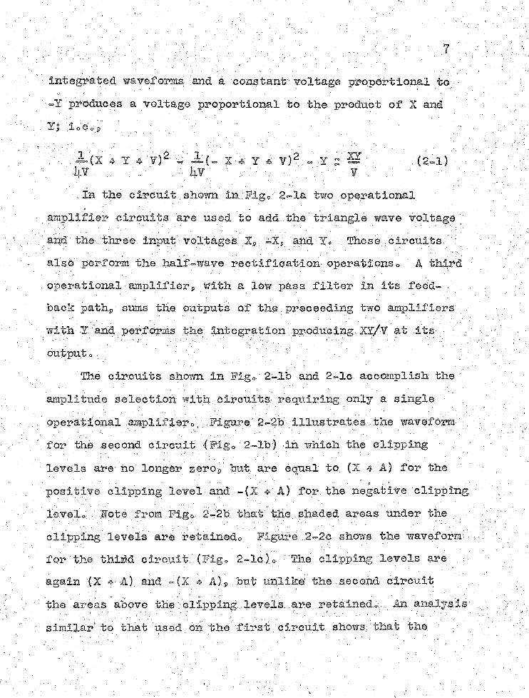
integrated waveforms and a constant voltage proportional to ~Y prodnees a voltage proportional to the product of X and
:;&(X 4 Y * Y)2 - X * Y *' Y)2 - Y S ’ , ■■ (2=1) r .
■; # . . t'/y 'y':-/ \ V / , : ' : : ■ . •.In the circnit. shown in: Fig »■ ,2-la tvsro operational
..amplifier cireuits are used to add...the triangle wave voltage ■' ■and the three input voltages X9 =X, and Y* These circuits ' also perform the half “Wave rectification-, operations o ' A third operational amplifierWith a low pass filter in its feedback pathp sums the outputs of the.preceeding two amplifiers with: Y'.' and: perfdrms; the Int egratlon: producing ■.^/Y at its- y;:
outputo - / y f ■ -i;.:' The circuits shown in Fig*.; 2-lb and 2-le accomplish the :
amplitude selection with circuits requiring only a single - operational amplifier», Figure 2=2b illustrates the waveform for the second circnit (Figo 2-lb) in which the clipping ; . : levels are no longer z e r o b u t are equal to (X 4 A) for the positive clipping levelyand .-(X # A) for the negative 'clipping. ■ leveley. 'Sote from Fig0 2-2b that; the., shaded, areas under the y ; ■. olipplng; levels, are retainedo Figure . 2-2c. shows the waveform - for the thind elreuit (Fig* 2-lc.)o The clipping levels are - again (X * A) and .~(X * A) g but unlike the second circuit the areas above the 'clipping..levels, .are retained*,. An analysis similar to that used on the first circuit . shows: that the •

average value of the shaded areas minus a voltage proportional to Y equals the product of X and Y times a scale factor that is inversely proportional to the half amplitude of the triangle waveo'
2-2« Factors Affecting Multiplication Accuracy and Frequency Responses ' ; - \'v ■ 1
The static multiplication accuracy depends on the accuracy of the triangle-voltage generator and on that of the amplitude-select ion circuits or The triangle must be symmetric about zero volts and have straight sides with sharp peaksc The amplitude-selection circuits must have accuracies in. the .' order of the multiplication accuracyr, although s©me errors tend to cancel in the push-pull circuits» .
The frequency res pons eP and hence the dynamic accuracy^ . depends on the frequency (?Icarrier11. frequency) of the triangle wave and the performance of the output filter» ideally the filter should be flat and have no phase shift, up to its cutoff frequency^ with Infinite attenuation, beyondo The filter :cut^@ff frequency should be adjusted to, • or slightly below, the first harmonic frequency of the triangle wave.* In general, the performance of diodes and amplifiers, deteriorates with increasing,carrier frequencyy hence a compromise must be made in static and dynamic accuracy, as in all modulation- type multipliers«
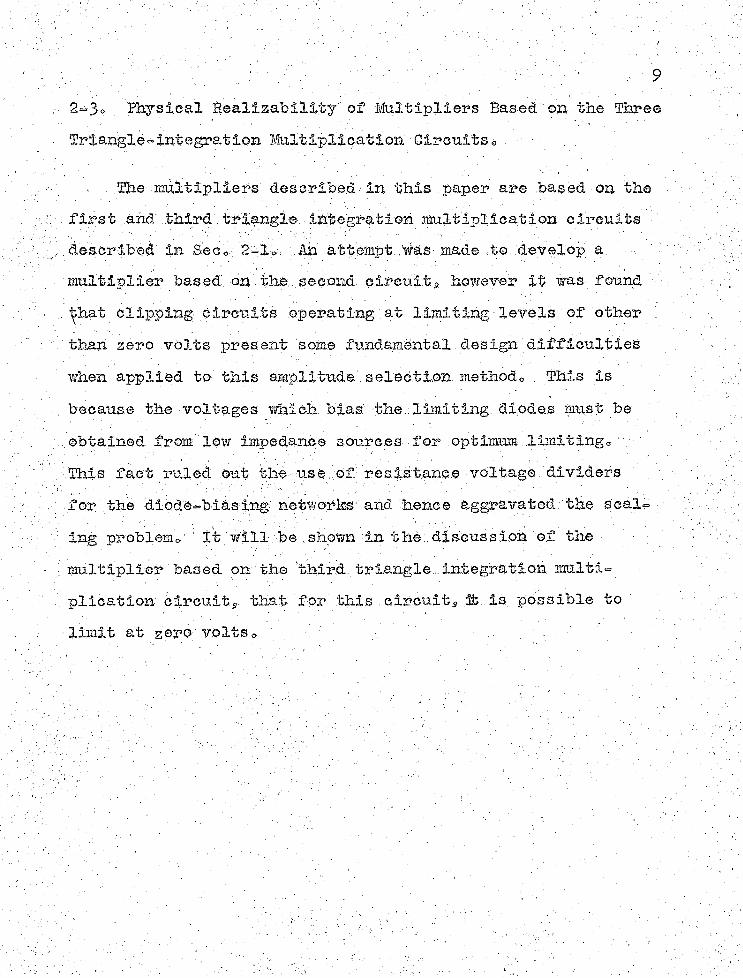
2~3o Physical Sealizablii^y-' of Multipliers Based, on the Three Triapglp-integratiba- Mhltiplicatioh CirctiitSe ■
, \ .The, multipliers' d.e3,crlheh - In this paper are based on the.. first.ahd: third .triangle ihtegfatioh multiplication circuits ' /described in Sec0 2-i0 • An attempt.',multiplier based., on the .second, circuits however it was found ■, . that clipping circuits operating at limiting levels of other !' than zero volts present some fundamental., design diffieulties, . when applied to this amplitude', seledti,oh method» . This is because the voltages which bias the.. limiting diodes' must be . obtained, from low impedance sources for optimum limltinge,This fact ruled out the use of resistance voltage dividers for the diodehbiasing networks and hence aggravated the seal- ing problemo.' '. It will'be shown' dn the.:.. discuS.s lorn.. of the . multiplier bas ed on the third., triangle . integration multi- plication' circuit,,, that for this .circuit» ,3fc .is possible to - limit at zero volts„ p ' ■ ...

CH&PTSB III THE PRECISIOH FEEDBACK LIMITER AID TOTIPLIEH 3fOo I,
3-l0 . Ih© Preex'sion Feedback .
• Figure 3-la Illustrates a limiter circuit employing voltage' feedback t© realise a.limiting characteristic that is a vast improvement over conventional shunt and series diode voltage limiters0 Figure 3-lo compares the actual transfer characteristics of both: a series limiter9 of the % type shown In Fig© 3«lbs and the precision feedback limitero It is observed that the precision limiter has a sharp break point that is independent of the characteristics of the diodes contained in the circuit»
$he operation of the feedback limiter is as follows=For positive: input voltage s.FD^ conducts s : and the c if cult acts like a,phase inverting operational amplifier of gain Diode forward resistance and contact potentials are effectively divided by the high loop gain of ,the feedback circuit©As the input voltage becomes negative9 begins to cut off©
D© Morrill and E© V© Batmis HDiode Limiters Simulate Mechanical Phenomena”P Electronics*.Nov© 19^29 p© 122©
Gr» A, • Korn and f © M© Korn* op» clt© s p© 292-293»^Ho Koerner and •(?,. A© Korn* 11 Function Generation.With
Operational Amplif iersn9 Electronics * Hov© 6S. 1939p p» 66=70.
. 10 ■ ' • ■

11/OOK WO K
H/CM- 6A//V D-C AMPL/F/ER
W O KA A A / V O — ZOOV
F / G . 3 - / a . P R E C /S /O M fETED BAC K J L /M tT E R .
100 K
F/G. 3 - / b C O H V E f i / r / O N A L S E P / E S L / M J T E R .
OUTPUT VOLTAGE
o.S VOLT - -
X . . /A/PUT VOLTAGE
PREC/S!O N FEEDBACK "" L/MJTERSER/ES L/M/TER
WITH 1/2 GALS - VACUUM D/ODE
F / G . 3 - / C " C H A R A C T E R / S T / C S O F T N E T W O L / M / T E R S A R E C O M P A R E D .

- ' . 12. This opens the feedback loop through Eg? o&using the high amplifier gain to cut off sharply bjr increasing' its cathode voltage 0 Diode Dg-limits the amplifier output voltage to some positive value| and feedback through keeps the summing point voltage^ hence the limiter output voltageff accurately at zeroo
3-2^ . Application of Precision Feedback limiter to MultiplierHOo 1 » ' ' • .■ ■ . . : . : ! ■
Figure 3-2 shows the circuit diagram of Multiplier Ho* 1®Two precision feedback limiters serve as amplitude selectors:' the upper limiter in Fig*;.3«-2 limits at voltages (referred to its; ' output) of less thah gerog a nd the lower at voltages greater than zero volts» Baiibrielc K2Z operational amplifiers s stabilized with Philbriek 22P chopper amplifiers to reduce d-c drift) are used in both limiters and in the output filtercA Details of the filter follow in See* 5-1*.' A self-contained triangle generator .(pot shown in Fig* 3^29, but described in Seco 5-2) that is mounted: on the multiplier chassis supplies a triangle wave with a p ke fundamental frequency»
The multiplier is amplitude scaled so that the output is 100 volts for inputs- of X - 100 volts and Y s 100 volts* in other . words the input-output relation is
'■*80 A0 Philbriek BesearcheSj, Bostonp Mass0? Specification . Sheets for E2X Operational. Amplifiers and 12P Chopper • Stabiliziiig Amplifiers* ' ~ ,

o R1 250K♦ — A A A A Z —
TRIANGLEINPUT
S-IZMNt
-H X O V X A A A
R 2 iM
V o
oTRiANGLE /NPUT
— w w - R3 i M
Ri' 250K — w w —
J-/2 XX/*— w w
/ A /
— W W - /?3y /M
R 4- 2 5 0 K -^VXAAA
3. /C/?5 lOO K A / V W -
- 30 7 K20 K WIRE q
W 0UNO POT.
R q * 2 5 0 K W X A A
/W V \ A - — /V W V V--------►
/28
vww%— / ? 5 / iOOK
+ 300V.
OUTPUT
ALL RES/STORS AR E ±JV . WIRE WOUND T Y P E SPA/R$: (RI, R !*) )(R R 2*) ifRS) R 3') iCR#) R 4*) AND(R5)R5') ARE MATCHED TO WITHIN ±0./%
EACH OTHER./ / , GALS VACUUM TUBE DIODES
F / G . 3 - 2 . C I R C U I T O F M U L T I P L I E R / INCORPORATING P R E C IS IO N L I M I T E R S .

HraiPBIER OUTFUT — (3-1)
Potentiometers are included in the filter amplifier to adjust the multiplier gain, hence accurately setting the condition given by Eqc 3=1? and to balance the Y input for minimum off set o ■ ;
The internal amplitude scale of the multiplier is a compromise between several conflicting factors<? The most important of these is that the sum or difference of X and Y, referred to the output of either limiter,, cannot exceed the ° half“amplitude of the triangle wave* The other'factors are:(1) the scaling must be kept sufficiently large to swamp out d=c offsets^ noise9 and 60 eps hums (2) the summing and feedback impedances must be kept within the driving limitations .of the:amplifiers contained within the multiplier, triangle generator? and external,function voltage sourcesf and (3) the amplitude scale must be kept Within the output voltage range of the limiter and filter amplifiers 0 The half-amplitude of the triangle wave generator used with this multiplier (see Seco 5-2 ) is 60 voltso Since., the multiplier is scaled for up to 100 volt, inputs? the X and Y inputs are reduced by a factor of ip in both limiters while the triangle input scale is unaffectedo Hence the triangle referred to the output of the limiters always exceeds "f he sum or ■difference of ,X and Y by at least 10 volts? and the sum of X9 Y? and the. triangle is never greater than 110 volts? which? with the load furnished

Toy■ the limiter feedback circuits and input Impedance of the output amplifier» is within the output-voltage swing capability of the Philbrick K2X= ' : ;
3-3o Performance of Multiplier Hoc 1»
, The performance of Multiplier IfOo 1 is summarized, below: Maximum D-G Offset at Output
—30 millivolts measured with either or both inputs grounded$ full amplitude on input that is not grounded©
Static AccuracyProduct accuracyg 0.0^^ of full scale inany one quadrant (full scale equals 200 voltss over range of -100 volts to 4 100 voltsK Product accuracy, 0=1^ of full scale in all four quadrants0 -
Dynamic Accuracy 3- /' . . /• Product .'.accuracyg 0,1^ of full scale for 1 cps $ 200 volt
peak-to-peak triangle wave times £ 100 volts»Ripple at Output
lol}: vOlts ‘peak-to-peak Measured with full amplitude on : both inputs©

CHAPTER IV'. THE PRECISIOH DEAD-SPACE LIMITER AHD'MULTIPLIER EOi 2 '
li.-lo The Precision Dead^Spaoe Limiter» '■ L
Figure Il-1 11 lustrates a' newly developed dead-space limiter circuit incorporating the 'deelrahle features of 'OtWr.- pre ': .c is ion. limiter circuits^ and having characteristics suitable ' for use as an amplitude' selector to implement / the. third aiirpli- tude selection m e t h o d U t i l i z i n g only a single, high 'gain •, dro amplifiers the circuit produces both- positive■and negative output voltages Xj and X2 ' limited at zero volts with, accuratej, Separately ad just able. breakpoint voltages ».; The breakpoints ;- are given by E^R/r^ and EgR/rp to within'0o05 volts at d-c provided that r^ and rg . exceed the, diode forward resistance ■ !by a factor of at least 29000 » . Actual. perf ormance'tests under - ,these conditions y using a chopper stabilized d-e amplifier * 1: confirm the 0o05 volt breakpoint accuracy at d-c.o ■ ' • ■
li.=.2 0 Appllcatipn. .of Precision Dea-d=space -Limiter - to Ivlulti- . . ,'plier .Hoo, 20 ,: -I \ ;■; . ' ' 't: -,’, g
. H«, iEoerher and .-.Hern9 . opd cit o' ' ! : ’■ V - ,Co " Ac,: Horny ."A Precision Dead-space Limiter for Triangle- -
'Integratibn Multipliersny ACL Memo Hoo" lljy Electrfcal Englheerihg- Dept & y: University of.: Arizonay Tucsony ' Arizona s Hov0 2959 * - . ' :

6 X
17
4^— x
Rz
150 KSOK///CU- 6A/M D-C A M PL/Ft ER
-E
O XX,
F / G . 4-/. P R E C / S / O A / D E A D - S P A C E L / M / T E R .

: / " ' :::: t x::'. - -- r": -: : ;..; '' ' : ' ; - -/:: -; '^8r. ' . Figure It-2 • gives the circuit of Multiplier No. 2 incor
porating the precision dead-space llpifero; The trianglegenerator designed. for Multiplier No«/:!'' is used ■ along with a -modified versioncf the.Multiplier No. 1 output filter.■■Low
; capacitance silicon diodes (Pacific Semiconductor type INol^)
and: a new operational, amplifier with'extended high frequency response'4- (UA/Model 1) are used in the dead-space limiter.
■ for optimum high speed, performance at the ^KG triangle fre- ,■ . quency. Performance test results are also given for the.
■■ slower Ehilhrlck :E2XV amfliflero • ’.As with Multlpiier■■ No.. 1» the limiter'' and output filter operatlqnal amplifiers are- , . stabilized with. Phllbfick K2P chopper amplifiers for minimum d-c drift. Potentiometers are included ■ in the-limiter to balance the. multiplier for minimum, d^c offsets and. adcurate,;
. i f our-quadrant mult ipli cat ion. ' .The amplitude scale of the input-output relation-and the ;
maximum input■ voltages are the same for Multiplier No. 1'as .■ for Multiplier No.- 2. Also, the factors influencing the internal amplitude scale are the same except where they■are modified by differences between the. amplitude selection methods
: - ^Pacific Bemiconduetor : Inc. 3 Culver Cityg California^ i: Data Sheets "for Pacific Semlconductor Fast Recovery Diodes.
. Eoerner s- 11 Plug-In Operational Amplif iers ' With Extended. High Frequency Response^^ ACL Memo No. 13, Electrical. Engineering Dept»$ IlBlVersity of Arizona, Tucson, Arizona, ■

R3 2S0KA A A A A
>e4 5<7A' A A A A Z ------
TR/ANGLEJNPUT
O
r °
+toov
3-/2 M M f
50K //£U POTRt wvw>
3 /O K r— WAA/'1 /rav
SK2P
/O K yS UBL/POT
v A A A A /'1 SOK HEL/POT
-100V -300 VnA A A A A
#3Z .25(7/C RQ-SO K
A l l RES/STORS SPOk/A/ A R £ * /% W/RE WOUND TYPES( R S ^ R S ' ) AND (R + t R + ' ) ARE M ATC H ED TO W /T H /N * 0 .1 * 7 * OF EACH OTHER.A IL D/ODES ARE PAC/F/C SEMICONDUCTOR TYPE /A/S43 SILICON FAST RECOVERY D/ODES.
OUTPU
/oo-O
VO
F /G . 4 - 2 C I R C U I T O F M U L T I P L I E R 2 /N C O R P E R A T /N G T H E P R E C IS IO N D EAD - SPACE L / M / T E R .

20used in eac."b. of the riinltiplierso The luterual. amplitude scale is chosen so that the T input is reduced by a factor of 1}. at the output of the dead=-space liinlter and the triangle input scale is unaffected* The »X and -X inputs are combined with >100 and -100 yolt reference voltages (obtained . from an analog computer reference supply) in the dead space limiter bridge biasing netvrorks to control the range of the . limiting levels in order to achieve four-quadrant multiplication* These biasing networks are adjusted so that .the break- . .. points range between 0 volts when the »X input is -100 volts and the -X input is *100 volts (refer to Fig* ij.-2)s and approximately 35 volts when the -g-X input is *100 volts and the -X input is -100 volts* Thus the limiting levels never exceed the difference, of.the Tinput'and triangle voltages| and near linear four-quadrant multiplication is achieved*
' Performance of Multiplier NoQ 2* '
Table 1 summarizes the performance of Multiplier Ho* 2 using both the- Philbrick K2X and University of Arizona UA/Model S operational amplifiers in the limiter* Test conditions are the same as those used'with Multiplier Ho* 1*: With the Phil- ■ brick K2X the output range is limited to between -50 volts and <50 volts since with the load condition placed on the amplifier by the limiter feedback circuits and input impedance ■ of the output' amplifierg the IC2X cannot deliver enough output

em?z,ent to allow operation over the *100, volt to -100 volt range. ■ : ' . ...
Table lo Stimmary of performance of Multiplier Eo0 2
TYPE OP OPERATIONAL AMPLIFIER USED 11 LIMITER
PHILBRICK K2X ■ UH1VERSITY OF ARIZONA
• MODEL 1• MAXIMUM' D-0 OFF
SET AT, OUTPUT ■ ' . 130 mv» ■ : 1^0 mv o. STATIC ACCURACY 0»2^ of
100 volts0,1^ of
200 voltsDY1AMIC ACCURACY WITH Ool eps TRIAHCLE WAVE
: TIMES :ilOO VOLTSGo 3^ of
100 volts0o2^ of
200 voltsDYIAMIC ACCURACY WITH 10 eps TRIANGLE WAVE '■
.. TIMES 2100 VOLTS. , .Ic4^ of
100 volts1<>3 of 200 volts
;RIPPLE AT OUTPUT . 1*$ volts ■ peak-to-pealc
loi> volts peak-to-peak ••

OMFEEE ? : OllfPW FILTERS AID TEIAliGLE GE1EMTOR
5-lo Output Filterso , .
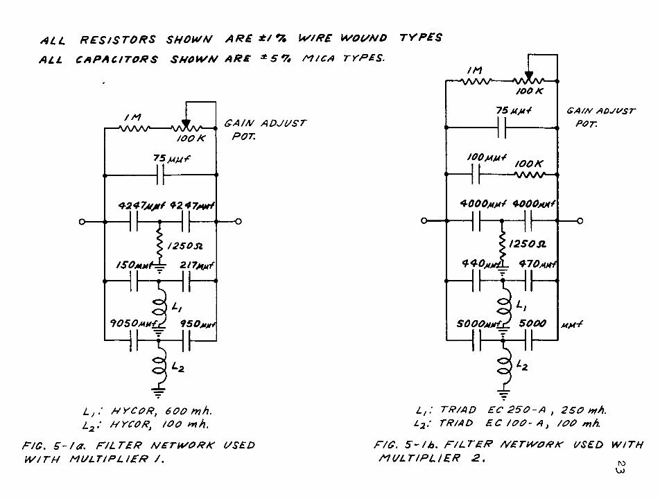
An attempt was made to employ modern network synthesis techniques for the design of the two filter networks used as . feedback impedances in the output amplifiers of/the multi- ' pliers* These circuits are shown in Fig* 5 ^ * Both filters have imaginary axis zeroes positioned at p and 10 kc to filter out the first and second harmonics of the £ kc triangle wave- fQrmg and have responses adjusted for minimum phase shift and peaking below 5 key with rolloffs of 6 db per octave beyond 10 kc* The inductor'Q8s and measured responses of, the. filters are:
A:* : Filter network used with Multiplier: 1 (Fig* 5'-la)» Inductor Q/s of approximately 75 with a response that is 62*5 db down at $ kc? £8 db down at 10 ke9. with a 1 db rise at kOO eps9 a nd a 9 db maximum
■: ■ - ; rise at 'ike*.. •Bo- Filter netwofk used with Blultipller 2 (Fig*. ^-lb) *
Inductor Qls of approximately li|.0 with a response that is 65 db down at 5 kca 60 db down at 10 kcs with a 1 db rise at 600 cpss and a lioY db maximum '
k - rise at I,! kc* . . ■
22
ALL R E S IS T O R S SHOWN A R E */ % W IR E WOUNO TY P E S
ALL CAPACITORS SHOW N ARE ± 5 % m C A TYPES.
G A IN A D JU S T POT.
75m m Y
4247M/t* +247/vH
< /250SI /50m u (-=: 2/7m m^
L j .' H Y C O R ) 6 0 0 iv h . l 2 : NYCORi / o o n H .
PIG. s - / a . F IL T E R NETW ORK USED W IT H M U L T IP L IE R /.
LOOK
GA/N ADJUST POT.
IOOK
+000/4M* Q-OOOma!
I2SOSL
SOOOMMtsL 5000
L t : TR /AD EC 2 5 0 - A } 2 SO mb.L2 : TRIAD E C I O O - A ) /OO mh.
FIG. S - t b . F IL T E R NETWORK USED W ITH M U L T IP L IE R 2 . M
w

V! I2AY.7 V2 6AN8
120 K
i50K / W/ S K
J0/4M* / w — •—vVWV-- °Z > / 24( ? / c ________
W W \ ^ —i "220 X 3-NE 2 NEOM BULBS
50K
68K<VIA
822.2 KJSK!W
270K 4 1KA M P L IT U D E
SOK'
ALL RESISTORS ARE ^ S 0?* TOLERANCE A M D ARE OF £ WATT RATING UNLESS INDICATED OTHERWISE O/ IS A SYLVANIA TYPE IA/39A GERMANIUM DIODE.
OUTPU O
IM
&
F IG . 5 - 2 . S KC T R IA N G L E G E N E R A T O R C IR C U IT .

5”20 Triangle Generator0 _ '
• The;triangle•generator designed for.the multipliers and • shoxm in Pig0 ^=2 consists of a Schmitt trigger with hysteresis driving a conventipna1 parallel-feedbaek integrator^ . The Schmift trigger functions as a voItage=aetuated switch that . switches he tween two stable output levels 0 This action when, incorporated between the input and output of an integrator ■ / ‘produces an analog to, a free=running multivibrators generating.
:ba squarewave voltage' at the input of the integrator and:-an h, .. •accurate 'triangle vhltage at the integrator , output 0 "
.: The performance specifications of the generator'are; ; .triangle repetition rate is p kc with a peak=to-peak voltage ;V;
' of 120 volts o Potent'lometers.' are Included in the circuit to adjust the triangle.amplitude^ symetry, and repetition rate.The output of the integrator is a-.c. coupled to remove: the
fd-c offset at the cathode of the cathode.follower that comt:-’ prises 'the . outputstage of the integrator. amplif iert •-• ' • - ' - . f
Millman and Ho- Taubs Pulse, and Digital Circuits,. McGraw-Hill Book- GOoS Incos pp7T6II~172s~To^~~
Ac Korn and Ts M0 Korns 0£o' c i t o . » pp» ITS-l^S-^Eo ho. Morrill and Rc V. Baum, op.» cito

GH4PEEB. ¥1 PtlBfHSE BEYE.BOPICSIPS AID OOIPABISOS WITE OTIIll i.LE~EEiOTRdElC. SIUEPIPEIERS ' .
6»X0 Snggested Farther' Developments =
. % \ development work carried out for the two multipliersdescribed in this paper was mainly directed at establishing the practical realizability and accuracy of minimum-circuitry multipliers based on the triangle-integratlon raetliodo The development work for the two multipliers is .not completes and there are several things that can be done to improve the performance and to further simplify the circuits of both of theme \
One thing that was established by the development work - was that - precis ipn l:lmiters.p when properly designed with high speed operational amplifiers and low capacity diodesg could be made to limit at rates greater than the kc rate used with Multipliers 1 and 2a Thus it appears" possible to Increase the triangle; frepuency .to. as; high as.. 10; kc and still, have adequate limiting action* ,. Increasing the triangle frequency would have two effects* Firsts it would improve the frequency response since the 11 carrier“ frequency would be further.separated from;the "modulating" frequencies; and second;, it would simplify the output filter because of the greater ease of filtering at higher frequencies* Further
=«

■ . ' . 2 7 /ref imement of the triangle generator can he made to Improvethe linearity of the triangle waveform*- The inevitable errors of the preeision-limiters will9 howevers limit the ultimate mnltiplieatipn accuracy so that triangle generator .improvements must be weighed against precision limiter errors o ■ ■ • ' ■ -
If the filter networks were incorporated in the output amplifier summing 'junctions^ then with a slight change in .circuit', configuratioh 'division .by implicit computation and generalized integration operations similar to those performed with time division multiplierss could be carried out by either multiplierHowevers since there are three, inputs to the output amplifier summing -junctions- in both, multipliers s a basic design problem exists in putting the filters in the summing junctions 6 y , - 1
, The existing filter networks, could stand some further refinement =' The phase shift below 100, ops should be made smaller and the. attenuation at the > and 10 kc triangle har» ' monic frequencies should be made greater» The attenuation, at these frequencies is limited by the.Q of the.indue tors s . hence in order to obtain greater attenuation^ higher Q, inductors, must be used*
•Q-c Ao. Korn9; n Interim Report On Two hew Electronic .Suitipl 1 ersw ACL Ifemo. Mo o' 8$ Electrical Engineering Dept 0 9 .University of Arizona^. Tuesons Arizona,, June, 1959°

In the final layout of the multiplier package it is possible for a single triangle generator to supply two or more multiplier channels^ fills would reduce the cost of several multipliers built into a single chassis unit* If this is done, howevers the maximum output-current limitations of the triangle generator should, be kept in mind and its output cathode follower redesigned for the increased load*
6-2Q Comparison of ffiultipiiers 'HOo 1 and 2 With Commercially Available All-Electronic; Multi'pllers »
The final Judgement of Multipliers Ho0 1 and 2 must be made by comparing them on a performance and cost basis with commercially available all-electronic multipliers with similar performances since if the designs were to be manufactured for commercial sale, then they would have to be competitive * One way of comparing the cost of all-electronic multipliers is to compare the relative circuit complexity and the number of operational ■amplifiers used in each multiplier channel* The quarter square types Reeves Model Cli.0li.-13 Diode Electronic
pMultiplier Console 2 and the triangle-integration types$ Phllbrick Models MU/D¥ Dupler Multiplier/Divider^ and
^Beeves Instrument Corp.» Carden Qlty, Eo BEAC Technical Bulletin 601* .Diode.Electronic Multiplier Console#^ o p i n r '19^K ~ . ■ ; : ~ ■
^Oeorge A* Philbrick. Besearchess Inc»9 Boston l6s Mass* # Specification Sheets for Phllbrick. Model Multiplier-Divider 9~~T9^9 ° ~

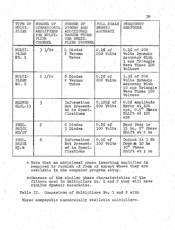
; . 2 9 : Multipl3.er=DIvider^" are two possible competitors in cost and' perf omanee* - Table II provides - a corap ar 5. si on of data from . 'the specifications of these three multipliers with data for'Multipliers Ho» 1 and '2= It is apparent that MultipliersHo, 1 and 2 are favorable designsf moreover that further, ref inement; of the designs to make them ' acceptable commerciallyis i worthwhile^ < . ■■ -- - : f-' ; -. .
■ , ^-George A 0. Philbrick Researches, Ihc o.9 Boston - 16s, Mass»$ Specification Sheets- for Philbrick Model. Multiplier-Divider^- 19^9 o~ *™ ■ ; .
30
' TYPE OF MULTIPLIER
HUMBER OF OPERATIOHAL AMPLIFIERS PER MULTIPLIER CHAHMEL
HUMBER OF DIODES AID ADDITIORAL VACUUM TUBES PER MULTIPLIER CHAHIEL
FULL SCALE STATIC ACCURACY '
FREQUEHCY . RESP0HSE
MULTIPLIEREOo 1
3 1/2* jp Diodes 2 Vacuum
TubesOol^.Of 200 Volts
Ool^ of 200 Volts-Dynamic Accuracy With 1 eps Triangle Wave Times 100 Volta**
MULTI#:. PLIESMOo 2
2 1/2* 6 Diodes 2 Vacuum
Tubeso w of 200 Volts
1*3% of 200 Volts .'Dynamic Accuracy With 10 ops Triangle Wave Times 100 Volts**
REEVES . 01i.01l=13
3 Information Hot Presented in Specifications
0ol23/ Of 200 VOlts0*5$ Amplitude Errdr at 100 eps s' 0o5° RMase Shift at 100 eps
PHIL-BRICKm / m
'■5 : 8 Diodes 3 Diodes
0*1# of" 100 Volts
Band' Pass is 15 kcs 5° Phase Shift at 2 kc
PHIL-BRICK
6 Information Hot Presented in Specifications
Qolfo of 100 Volts
Output is.3 db Down Ub 10 kc 10° Phase Shift at 1 kc
-i;- Eote that an additloiial pirns e Inverting' amplifier is required to furnish -X from 4X except'where: they are available in the computer program setup-
^Because’ of the similar phase characteristics of the .filters/used in Multipliers Ho0 1 and 2 they will have similar dynamic accuracies.
Table H o Comparison .of Multipliers Eoo .1 and. 2 with three comparable commercially available multipliers.

BIBLIOGRAPHY"
( Books) : - . ;. JoHnson9 Co L5 9 Analog Computer Teohnlqiies3 McGraw-Hill
Book Co.op Inc®p'HeiFlOnk Citys Ho Yop lp$6a .Kornp Go Ao■and To Mo 9 Electronic Analog Computers9 2nd
Edo $ McGraw-Hill Book Coo p. Inco p Hew York .Cltys .. Ho Hop 19560 ' .
Mlllkartp Jo- and Taub9 He »• - False and Digital Circuits 9 IcGraw-HIll. Book, OOo-p, Ineep Mew York City5 Mo Yep
... 2.956o
(Articles in a periodical)Eoernerp Ho and Kor% G0 A o s, ,lFunction'Generation With
Operational Am.plifiersf?9 . Electronics s Novo 6S 1959»Mayerg R, Ao and Davis $ IL B» nTrlangle-Ware Analog
■ . S®altIplier?:Is Electronic a> Augo 1956 oMorrillp Go Do; and Baum,-, He Vo 9 _,TDIode Limiters Simulate •
Mechanical Phenomenan 9 Electronics9 Move 69 1959» ■. Pfeiffer9 Be Eo g. nA Four Quadrant Multiplier" 9 Trans
actions of Professional Group on Electronic .Computers^ Institute Of Radio Engineersa Septic 1959°
(Documents) . ' ’ ;•General Electric Goeg Phoenix$ Arizona^ Advance Bulletin
2S §S Analog Computing, Modules» 1959 o ; =: ■Koerner5, Ho 9 11 Plug-In Operational Amplifiers With Extended
- High Freqo.ency .Response!il ACL Memo Ho0 13s Electrical .. Engineering Deptog University of Arizona9 Tucson, Arizona9. ®ehoS 1960o , - ; , .J;
31

.... : - : - . . .. : : : 32Eoriij, Go Ao 9 tfA Precision Dead-Spae© Limiter for Triangle^
Integration Multipliers |;S- ACL Memo ifOo ills Electrical Engineering Dept0 s UniTersity of Arizona,Incson^ Arizona, Not0 19$9°
Korn,' Go A», n Interim Report On Tw.o : Eew Electronic•- Multipliers^^ AGL Memo NOo 8g Electrical Engineering
Dept*, University ofr-ArizonaS) lacs on, Arizona,June, 19^9o
Pacific Semiconductor Inco, Oulver City,. California,Data 8h.eete for Pacific . Semic.oniuctor. Fast Recovery Diodes & "" ' ' " \
George Ao Philbrlck Researches, .inCo, .Boston 16,; Massachusettsg .Specification.Sheets for Phllbrlck Model aro/D¥ Duplex. MultlplierTDivider,
George A® Philbrlck Researches,. InCo $, Boston 16,Massachusetts, Specification. Sheets for Philbrlck
. Model Multipller-Divlder, 1939 qGeorge A. Philbrlck Researches, Incos Boston 16,
Massachusetts, Spec if Icatlon Sheets for. Philbrlck Model K2-X Operational Amplifi.e.r and K2-P Stabilizing Amplifier', 1959 ° „
Reeves Instrument Oorp*, Garden City, -Ho Yos REAP Technical Bulletin 601, Diode Electronic.Multiplier