two-way steel floor system using open-web joists · using open-web joists by john a. schaad, b.s. a...
TRANSCRIPT

Two-Way Steel Floor System
Using Open-Web Joists
by
John A. Schaad, B.S.
A Thesis submitted to the Faculty of the Graduate School,
Marquette University, in Partial Fulfillment of
the Requirements for the Degree of Master of Science
Milwaukee, Wisconsin August, 2005
i
Preface
Minimizing floor-to-floor heights in mid- to high-rise buildings is a concern held by both
engineers and architects. Many attempts have been made in steel construction to adopt
design philosophies that utilize structural floor members with high span/depth ratios.
These designs, however, have been limited to floor systems that predominantly span in
one direction. The primary objective of this thesis is to investigate the structural
feasibility of interlocking open-web steel joists to form a panelized two-way steel floor
system.
This thesis includes a detailed discussion of the fabrication of the proposed floor
system. A complete description of a proposed construction sequence is also presented.
Finally, the structural behavior of the floor system is demonstrated under static loading.
Conclusions were made discussing the benefits of this new system as well as
recommendations for the direction of further investigation.

ii
Acknowledgements
First and foremost, I would like to thank my advisor, Dr. Chris Foley, for his time,
guidance, and willingness to listen as my proposed floor system design evolved. I want
to extend my appreciation to my other thesis committee members: Dr. Stephen Heinrich
and Dr. Sriramulu Vinnakota. I am also extremely grateful for the guidance and
suggestions that I received from David Samuelson at Nucor.
In addition, I want to extend my gratitude to my parents, John and Annette
Schaad, for their continued support and encouragement during my pursuit of a graduate
degree in civil engineering. Finally, I offer heartfelt thanks to my fiancé, Erin Morin, for
her support and patience while I have been away in Milwaukee, Wisconsin.
iii
Table of Contents
List of Figures…………...……………………………………………………………….vi
List of Tables…………...……………………………………………………………...…x
Chapter 1: Introduction and Literature Review……………………...…….1
Section 1.1 Introduction…………………………………………………….….1
Section 1.2 Stub-Girder System………………………………………………..2
Section 1.3 Girder-Slab……….………………………………………………..6
Section 1.4 AISC Multi-Story Residential Construction Competition………...8
Section 1.4.1 Structural Steel/Autoclaved Aerated Concrete (AAC)
Composite Floor System…………………………..……....9
Section 1.4.2 Stiffened Plate Floor Deck……………………………….12
Section 1.5 Staggered-Truss………………………………………………….14
Section 1.6 Open-Web Steel Joist Construction………………………...........18
Section 1.6.1 Dry Floor Construction…………………………..............18
Section 1.6.2 Composite Steel Joists…………………………...............20
Section 1.6.3 Composite Girders….........................................................23
Section 1.7 Space Trusses….…………………………………………………24
Section 1.8 Synthesis of Past Literature and Direction for Present
Research…………………………………………………………28
Chapter 2: Proposed System Fabrication and Erection…....……..............30
Section 2.1 Introduction……………………………………………………....30
Section 2.2 Fabrication ……………………………..………………………..31
iv
Section 2.3 Erection Sequence……………….……………………………….35
Chapter 3: Structural Behavior……………………...……………..………41
Section 3.1 Introduction….………………...………………………………....41
Section 3.2 Plate Bending…………………………………………..………...41
Section 3.3 Two-Way Concrete Floor Systems...…………………………….45
Section 3.4 K-Series Joist Selection (One-Way System)…….………………47
Section 3.5 Structural Analysis……………………………………………….50
Section 3.5.1 FEA Element Types and Modeling Assumptions………..50
Section 3.5.2 Traditional Joist Analysis and Results…..……………….52
Section 3.5.3 Proposed System Panel Design…………………………..59
Section 3.5.4 Modeling the Proposed Design…………………………..64
Section 3.5.5 Connection Design ……..………………………………..73
Section 3.6 Girder Design ……..……………………………………………..80
Chapter 4: Composite Design………………………...……………..………85
Section 4.1 Introduction….………………...…………………………………85
Section 4.2 Proposed System’s Composite Capabilities………………….......86
Section 4.3 Composite Girders..……...………………………………………93
Chapter 5: Conclusions and Recommendations…...…..…………..………96
Section 5.1 Summary….………………...…………………………………....96
Section 5.2 Conclusions….………………...…………………………………97
Section 5.3 Recommendations for Future Research………………………...100
References…………………………………………………..…...…..…………..……..102
Appendices………………………………………………….…...…..…………..……..107

v
Appendix A: Results of Proposed System’s Member Sizes……………………107
Appendix B: Calculations for Non-Composite Girders…………………...……112
Appendix C: Calculations for Composite Girders…………………...……..…..118
vi
List of Figures
Figure 1.1 - Stub-Girder System (Chien 1993)................................................................... 2
Figure 1.2 - Conventional and Modified End Details (Ahmad 1992) ................................ 5
Figure 1.3 - Girder-Slab System (Girder-Slab 2005a)........................................................ 6
Figure 1.4 - “Gooseneck” Connection Detail (Girder-Slab 2005b).................................... 8
Figure 1.5 - Typical AAC Floor System Details (Itzler 2004) ........................................... 9
Figure 1.6 - Possible Composite AAC Assembly Details (Adapted From Original
Proposal Figures (Itzler 2004)) ......................................................................................... 11
Figure 1.7 - Stiffened Plate Floor Deck (Hassett 2004).................................................... 13
Figure 1.8 - End Connection (Hassett 2004) .................................................................... 13
Figure 1.9 - Connection of Modules (Hassett 2004)......................................................... 14
Figure 1.10 - Staggered-truss System (Scalzi 1971)......................................................... 15
Figure 1.11- Transfer of Lateral Loads to Trusses (Scalzi 1971) ..................................... 16
Figure 1.12 - Example of Dry Floor System (Adapted from (Newman 1966)) ............... 19
Figure 1.13 - Gypsum-Plank Details (Fang 1968)............................................................ 19
Figure 1.14 - Composite Steel Joist System (Samuelson 2002) ....................................... 20
Figure 1.15 - Composite Joist Flexural Model (Adapted From (Samuelson 2002)) ........ 21
Figure 1.16 - Composite Girder System with Open-Web Joist Framing (Rongoe 1984). 23
Figure 1.17 - Example of End Fittings and Node Complexity (El-Sheikh 1993)............. 25
Figure 1.18 - Top Joint Shown (Composite Option) and Member Shear Stud (El-Sheikh
2000) ................................................................................................................................. 26
Figure 1.19 - Layout of Catrus Truss Model (El-Sheikh 2000)........................................ 27
Figure 2.1 - Non-Dominant Joist ...................................................................................... 31
vii
Figure 2.2 - Dominant Joist .............................................................................................. 33
Figure 2.3 - Connection Elements .................................................................................... 34
Figure 2.4 - Connection Detail.......................................................................................... 34
Figure 2.5 - Phase 1 of General Erection Sequence.......................................................... 35
Figure 2.6 - Phase 2 of General Erection Sequence.......................................................... 36
Figure 2.7 - Phase 3 of General Erection Sequence.......................................................... 37
Figure 2.8 - Phase 4 of General Erection Sequence.......................................................... 38
Figure 2.9 - Phase 5 of General Erection Sequence.......................................................... 40
Figure 3.1 - Plate Geometry.............................................................................................. 42
Figure 3.2 - Moment Distribution in a Simply-Supported Square Plate........................... 45
Figure 3.3 - Variation of Positive Moment Across the Width of Critical Sections
Assumed in Two-Way Concrete Design (Adapted From (Nilson 1991)) ........................ 46
Figure 3.4 - Sample of Moment Coefficient Table (Adapted from (Nilson 1991)) ......... 47
Figure 3.5 - K-Series Joist Selection................................................................................. 48
Figure 3.6 - Joist Self-weight............................................................................................ 49
Figure 3.7 - Frame Element Internal Forces and Moments (Adapted from (CSI 2004)) . 51
Figure 3.8 - Axes about Which Buckling Can Occur ....................................................... 52
Figure 3.9 - Reduction of K Factor Due to Slab Presence................................................ 53
Figure 3.10 - Traditional Joist Model ............................................................................... 55
Figure 3.11 - Traditional 16K9 Member Numbering ....................................................... 56
Figure 3.12 - Axial Force Distribution in a the 16K9 Model ........................................... 56
Figure 3.13 - Moment Distribution in a the 16K9 Model................................................. 56
Figure 3.14 - Preliminary System Designs ....................................................................... 61
viii
Figure 3.15 - Preliminary Joist Intersections .................................................................... 62
Figure 3.16 - Plan View of Proposed Design ................................................................... 63
Figure 3.17 - Proposed System’s Joist Models................................................................. 64
Figure 3.18 - 3D View of SAP2000 Proposed System Model ......................................... 65
Figure 3.19 - String Action Axial Forces.......................................................................... 66
Figure 3.20 - Deformed Panel........................................................................................... 68
Figure 3.21 - Axial Force Distribution in Proposed System............................................. 68
Figure 3.22 - Spring Analogy for Non-Dominant Joists................................................... 70
Figure 3.23 - Moment Distribution in Proposed Model ................................................... 71
Figure 3.24 - Moment Distribution in a Dominant Joist with Additional Web Members
Removed ........................................................................................................................... 72
Figure 3.25 - Cruciform Connection................................................................................. 74
Figure 3.26 - Alternate (Welded) Connection .................................................................. 75
Figure 3.27 - Chosen Connection Detail........................................................................... 77
Figure 3.28 - Connection Loads........................................................................................ 77
Figure 3.29 - Bolt Location............................................................................................... 78
Figure 3.30 - Load Cases .................................................................................................. 81
Figure 3.31 - Variation in Maximum Moment ................................................................. 81
Figure 3.32 - Reactions from Proposed System................................................................ 82
Figure 4.1 - Partially Composite System .......................................................................... 87
Figure 4.2 - Fully Composite Two-Way Joist System...................................................... 88
Figure 4.3 - Fully Composite System Using Two-Way Steel Decking............................ 90
Figure 4.4 - Supporting Girder Moments ......................................................................... 91
ix
Figure 4.5 - Proposed FE Model....................................................................................... 93
Figure 4.6 - Composite Girder Details.............................................................................. 94
Figure A.1 - Joist Labeling ............................................................................................. 107
Figure B.1 - Traditional Girder Loading......................................................................... 113
Figure B.2 - Girder Supporting the Dominant Joists ...................................................... 114
Figure B.3 - Girder Supporting Non-Dominant Joists.................................................... 116
Figure B.4 - Moment Diagram of Girder Supporting Non-Dominant Joists .................. 117
Figure C.1 - Composite Section...................................................................................... 119
Figure C.2 - Girder Loads............................................................................................... 119
Figure C.3 - Loading on the Girder Supporting the Dominant Joists............................. 123
Figure C.4 - Loading on the Girder Supporting the Non-Dominant Joists..................... 128
x
List of Tables
Table 3.1 - Top Chord Results for a Traditional 16K9..................................................... 57
Table 3.2 - Bottom Chord Results for a Traditional 16K9 ............................................... 58
Table 3.3 - Web Tension Member Results for a Traditional 16K9 .................................. 58
Table 3.4 - Web Compression Member Results for a Traditional 16K9.......................... 58
Table 3.5 - Joist Self-weight ............................................................................................. 73
Table 3.6 - Girder Selection.............................................................................................. 84
Table 4.1 - Resulting Girder Sizes.................................................................................... 95
Table 5.1 - Summary of Final Floor Panel Configurations .............................................. 98
Table 5.2 - Comparison of System Self-weights .............................................................. 99
Table A.1 - Chord Member Design for Outer Non-Dominant Joists ............................. 108
Table A.2 - Chord Member Design for Outer Non-Dominant Joists ............................. 108
Table A.3 - Chord Member Design for Dominant Joists................................................ 109
Table A.4 -Top Chord Results for Dominant Joists (Double Angle) ............................. 109
Table A.5 - Web Tension Members (Outer Non-Dominant Joists)................................ 110
Table A.6 - Web Tension Members (Inner Non-Dominant Joists) ................................ 110
Table A.7 - Web Tension Members (Dominant Joists) .................................................. 110
Table A.8 - Web Compression Members (Outer Non-Dominant Joists)........................ 111
Table A.9 - Web Compression Members (Inner Non-Dominant Joists) ........................ 111
Table A.10 - Web Compression Members (Dominant Joists) ........................................ 111
Table C.1- Components of a Fully Composite Girder (Traditional System).................. 120
Table C.2 - Deflections Along Various Load Stages (Traditional System) ................... 121
Table C.3 - Plastic Section Components (Traditional System) ...................................... 122
xi
Table C.4 - Components of Fully Composite Girder (Supporting Dominant Joists) ..... 124
Table C.5 - Deflections Along Various Load Stages (Girder Supporting Dominant Joists)
......................................................................................................................................... 125
Table C.6 - Plastic Section Components (Girder Supporting Dominant Joists)............. 127
Table C.7 - Components of Fully Composite Girder (Supporting Non-Dominant Joists)
......................................................................................................................................... 129
Table C.8 - Deflections Along Various Load Stages (Girder Supporting Non-Dominant
Joists) .............................................................................................................................. 129
Table C.9 - Plastic Section Components (Girder Supporting Non-Dominant Joists)..... 131
1
Chapter 1 Introduction and Literature Review
Section 1.1 Introduction
When floors are being designed in commercial or residential settings, there has to be
consideration on the part of the designer to identify the impact that the design will have
on the entire building. The depth of floor design chosen may profoundly affect the
overall height of mid- to high-rise buildings. Therefore, a desire to minimize floor depths
in buildings, based on innovative floor assemblages, is present for both architects and
engineers.
The definition of the phrase “floor-to-floor” height is the distance from the top of
a floor to the top of the next floor. This height is made up of three main components: the
depth of the floor construction, the “sandwich,” and the distance from the top of the floor
to the top of the architectural ceiling. The “sandwich” area contains parts of the
electrical, communication, fire protection, HVAC (HVAC ductwork takes up the most
space), and plumbing systems. It should also be noted that the depth of construction
includes floor slab thickness and the depth of the supporting members. Designers should
attempt to individually minimize one of the three main components or allow them to
share functions in the same space (Kirmani 2000).
The structural methodologies that attempt to minimize floor-to-floor heights,
which are reviewed in this paper, will be limited to steel systems or systems compatible
with structural steel framing. The construction topics discussed include stub-girders,
Girder-Slab, two recent AISC competition proposals, staggered-truss, composite steel
joist, and space truss floor systems. While each system offers a unique set of advantages,
2
it is the author’s opinion that an additional design alternative should be investigated.
This new alternative is a two-way steel floor system using open-web joists.
Section 1.2 Stub-Girder System
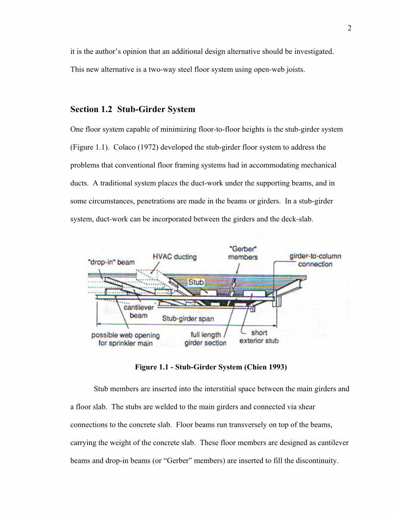
One floor system capable of minimizing floor-to-floor heights is the stub-girder system
(Figure 1.1). Colaco (1972) developed the stub-girder floor system to address the
problems that conventional floor framing systems had in accommodating mechanical
ducts. A traditional system places the duct-work under the supporting beams, and in
some circumstances, penetrations are made in the beams or girders. In a stub-girder
system, duct-work can be incorporated between the girders and the deck-slab.
Figure 1.1 - Stub-Girder System (Chien 1993)
Stub members are inserted into the interstitial space between the main girders and
a floor slab. The stubs are welded to the main girders and connected via shear
connections to the concrete slab. Floor beams run transversely on top of the beams,
carrying the weight of the concrete slab. These floor members are designed as cantilever
beams and drop-in beams (or “Gerber” members) are inserted to fill the discontinuity.
3
The stubs provide a relatively small addition of material that increases the
distance between the compressive concrete slab and the supporting girder. This increase
leads to a greater moment of inertia of the stub girder to resist bending (Wang 1995).
Interestingly, Chien (1993) notes that because tension and shear generally govern the
girder sizing, its required depth is not particularly span dependent (unlike conventional
systems).
Colaco (1972) concluded in his original paper that the advantages of the stub-
girder system when compared to a conventionally framed panel are:
1) A reduction in steel required in the girder due to the greater depth.
2) A reduced amount of steel in the floor beams due to continuity. There is also a
simplification of the end connection details of the floor beams due to lower shear
values.
3) An estimated 25 % reduction in the structural steel in the floor and approximately
15 % of the structural cost of the floor system.
4) A drop in total depth of approximately 8 in. between the top of the slab and the
ceiling. This results in a lower floor-to-floor height and additional material
savings in the exterior window wall system for the building.
Chien (1993) reflects upon several changes that have been made to the original
proposed stub-girder system, namely:
- Reduction in girder depth.
- Use of partial-height end plate stiffeners rather than full-height fitted stiffeners or
elimination of stub stiffening by using them only when required.
4
- Reduction in stub welding.
- Increased emphasis on slab reinforcement.
- The truncation of girder bottom chord to accommodate services near supports.
To gain perspective on typical system dimensions, Chien (1993) explains that in
Canadian construction, stub-girders span about 12 m (39.4 ft.), often from core to exterior
wall in conventional office buildings. The secondary floor beams would then span 8-12
m (26.2 – 39.4 ft.), with 9 m (29.5 ft.) being the most common span length. Floor beams
typically range in depth from about 0.3 to 0.5 m (12.2 to 18.1 in.), placed on 2.5 to 3.5 m
(8.2 to 11.5 ft.). This, of course, depends upon the structural module and deck span. A
typical deck-slab system consists of a 75 mm (3.0 in.) deep wide-rib profile deck with
approximately 75 mm (3.0 in.) of normal density (ND) concrete or 85 mm (~ 3.5 in.) of
semi-low density (SLD) concrete on top.
Two accepted methods of modeling a stub-girder include using either a finite-
element analysis or modeling the system as a Vierendeel Truss. In the Vierendeel truss
model, the deck-slab serves as a flexural-compression top-chord, while the full-length
steel girder acts like a flexural-tensile bottom-chord. The steel stubs, in turn, serve as the
shear stubs in the Vierendeel girder (Chien 1993). Refer to Wang (1995) for a
description of a nonlinear ultimate strength analyses, using both the vierendeel and finite
element methods.
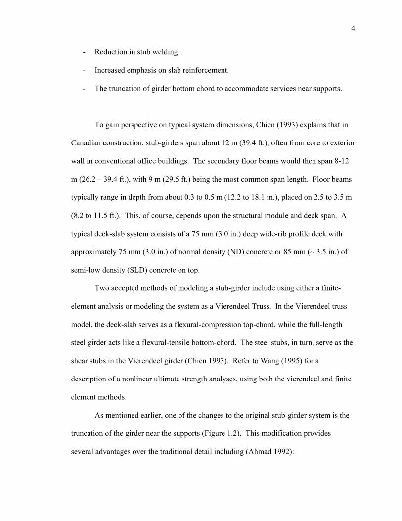
As mentioned earlier, one of the changes to the original stub-girder system is the
truncation of the girder near the supports (Figure 1.2). This modification provides
several advantages over the traditional detail including (Ahmad 1992):
5
1) Crack control of the concrete slab is provided near the column connection.
2) More room available for stud connection, eliminating an overcrowding of shear
studs.
3) A wider duct space is introduced below the end stub at the girder end. This
consequentially provides a bigger space for utility services such as fire sprinkler
mains.
4) An end detail offering an option of using a single-angle connection between the
column and deeper end stub, therefore eliminating any coping required in a
conventional end detail.
Figure 1.2 - Conventional and Modified End Details (Ahmad 1992)
Modifying the end detail creates some structural concerns. If the stub-girder
configuration is being designed for negative moment over the columns, the conventional
stub-girder detail would be more appropriate due to the drop in moment of inertia of the
modified stub-girder detail at the ends (Ahmad 1992). Another concern is the welded
connection between the bottom chord and the extended end stub. Stress concentration in
this area can lead to connection failure. Test results demonstrated that performance of
6
this connection was excellent during the ultimate load stage; however, the authors
cautioned that further finite-element analysis should be performed (Ahmad 1992).
Section 1.3 Girder-Slab
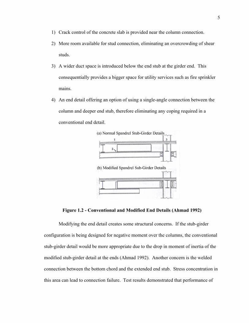
Girder-Slab is another relatively recent floor system in which engineers set out to
minimize floor-to-floor heights. The idea behind its development is to use a prestressed,
precast concrete plank and steel system (Figure 1.3) that could replace plank and bearing
wall construction (Naccarato 2000). More specifically, the technology creates a
monolithic structural assembly using precast hollow-core slabs with an integral steel
girder (Cross 2003).
Figure 1.3 - Girder-Slab System (Girder-Slab 2005a)
In 1993, there was a revision to the Building Officials and Code Administrators
(BOCA) Seismic Section that deterred the use of block bearing walls in low- to mid-rise
structures. In light of these changes, Constanza Contracting Company, Fisher Steel, and
O’Donnell & Naccarato Inc. joined together and created Girder-Slab Technologies, L.L.C
(Naccarato 1999). Initial testing of the Girder-Slab system used a dissymmetric cross-
7
section consisting of a lower tee cut from a W8x40 and an upper tee from an S3x7.5.
After testing, it was concluded that composite action was developed between this section,
the grout, and the precast slab. Formal independent testing followed at Drexel
University, where it was decided that by castellating a W-section (W10x49 in this case)
and welding a 1 in. x 3 in. continuous flat bar (serving as the upper flange), a
dissymmetric beam could be derived to serve as a more efficient steel bearing member
for precast slabs (Naccarato 2001).
Referring to Figure 1.3, the dissymmetric beam (known as the D-BeamTM Girder)
acts compositely with the concrete planks, enabling the floor to better support residential
live loads. The composite action is accomplished by first breaking small 8 in. sections
called “knockouts,” scribed at the end of each plank core. Next, debris from this action is
shoved back into the core to form a dam. Then, reinforcing bar is run through the open-
web of the D-Beam, placed into the hollow-core openings, and grouted into place (Cross
2003).
The resulting slab thickness of this structural arrangement is 8 in. An 8 in. slab is
supported by a DB-8TM girder while a DB-9TM girder is necessary if an additional 2 in.
concrete topping is added. Slab span lengths for this system are reported to span as much
as 28 ft. (Cross 2003). The steel girder spans are shorter, with lengths of up to 15 ft. If a
girder span increase is necessary due to the building layout, a “gooseneck” connection
detail can be introduced at the columns (Figure 1.4). By welding the connection to the
columns, a span increase of up to 20 ft. or 22 ft. is possible (Veitas 2002).
8
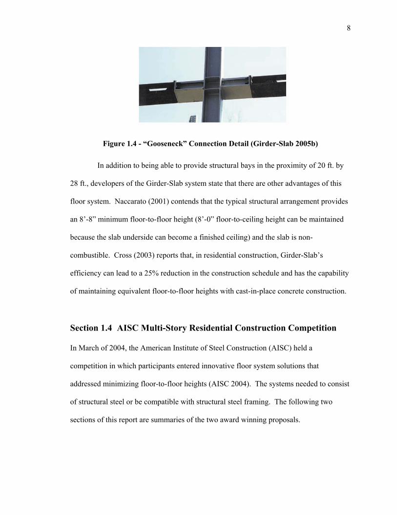
Figure 1.4 - “Gooseneck” Connection Detail (Girder-Slab 2005b)
In addition to being able to provide structural bays in the proximity of 20 ft. by
28 ft., developers of the Girder-Slab system state that there are other advantages of this
floor system. Naccarato (2001) contends that the typical structural arrangement provides
an 8’-8” minimum floor-to-floor height (8’-0” floor-to-ceiling height can be maintained
because the slab underside can become a finished ceiling) and the slab is non-
combustible. Cross (2003) reports that, in residential construction, Girder-Slab’s
efficiency can lead to a 25% reduction in the construction schedule and has the capability
of maintaining equivalent floor-to-floor heights with cast-in-place concrete construction.
Section 1.4 AISC Multi-Story Residential Construction Competition
In March of 2004, the American Institute of Steel Construction (AISC) held a
competition in which participants entered innovative floor system solutions that
addressed minimizing floor-to-floor heights (AISC 2004). The systems needed to consist
of structural steel or be compatible with structural steel framing. The following two
sections of this report are summaries of the two award winning proposals.
9
Section 1.4.1 Structural Steel/Autoclaved Aerated Concrete (AAC)
Composite Floor System
The first place prize recipient in the AISC competition was Itzler (2004). The idea of this
proposal is to develop a floor system where autoclaved aerated concrete (AAC) floor
panels and structural steel act compositely to provide a light weight solution to
minimizing floor-to-floor heights. Dr. Axel Eriksson, in Sweden, invented the building
material in 1924, while its introduction to the United States took place around the early
1990’s. AAC has been used in precast floor and roof panels for many years. However,
the idea of this material acting compositely with structural steel to achieve floor spans of
up to 40 ft. is a new concept.
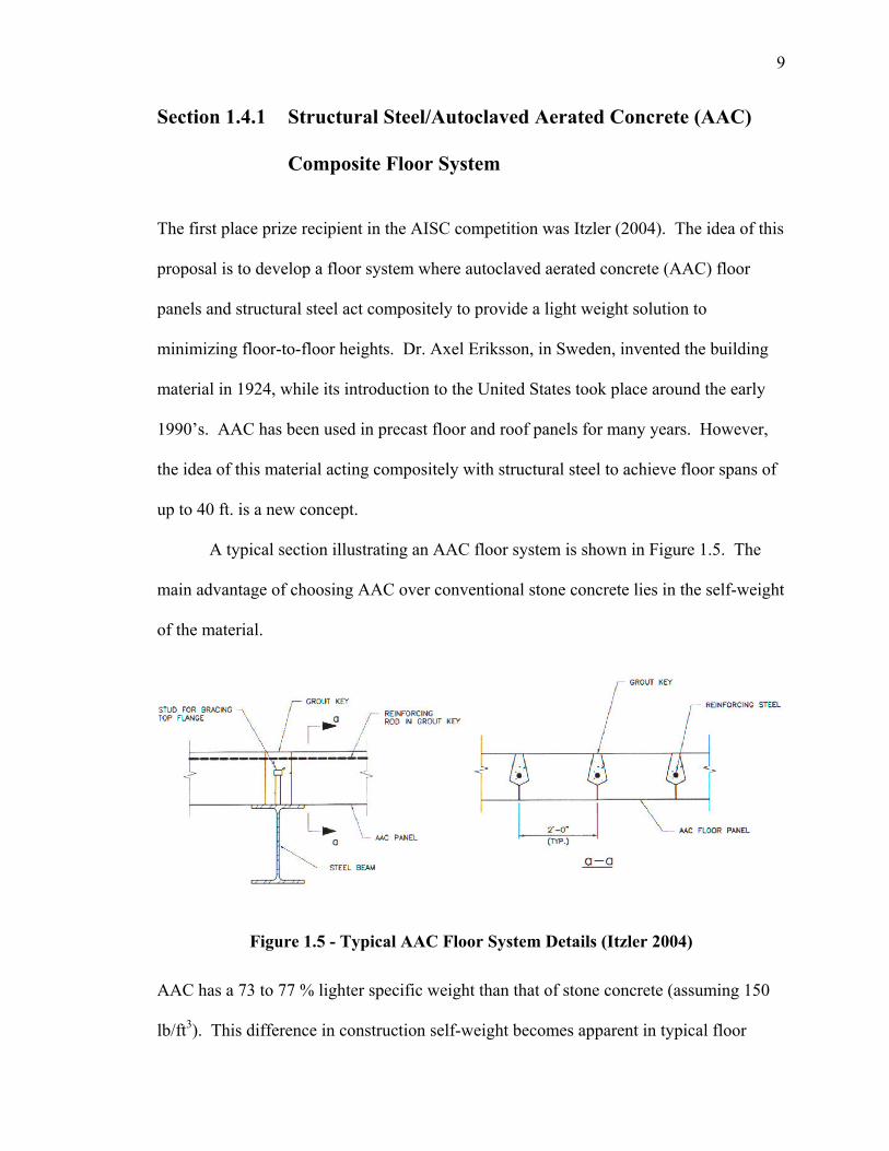
A typical section illustrating an AAC floor system is shown in Figure 1.5. The
main advantage of choosing AAC over conventional stone concrete lies in the self-weight
of the material.
Figure 1.5 - Typical AAC Floor System Details (Itzler 2004)
AAC has a 73 to 77 % lighter specific weight than that of stone concrete (assuming 150
lb/ft3). This difference in construction self-weight becomes apparent in typical floor
10
construction. An 8 in. precast hollow core slab weighs 70 psf, while an 8 in. AAC slab
weighs only 30 psf.
Schematic studies have demonstrated economical benefits of choosing AAC
construction over other residential building slab systems. For instance, the reduced dead
loads can create savings when sizing foundation members (e.g. piles or drilled piers),
transfer girders, and columns. Significant reduction in dead loads also inherently reduces
the seismic loading on the lateral load resisting system of a building. Additionally, AAC
construction can limit requirements for building insulation (in certain climatic conditions)
because the material’s “R” values are much higher than those describing normal weight
concrete.
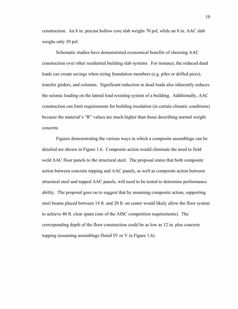
Figures demonstrating the various ways in which a composite assemblage can be
detailed are shown in Figure 1.6. Composite action would eliminate the need to field
weld AAC floor panels to the structural steel. The proposal states that both composite
action between concrete topping and AAC panels, as well as composite action between
structural steel and topped AAC panels, will need to be tested to determine performance
ability. The proposal goes on to suggest that by assuming composite action, supporting
steel beams placed between 14 ft. and 20 ft. on center would likely allow the floor system
to achieve 40 ft. clear spans (one of the AISC competition requirements). The
corresponding depth of the floor construction could be as low as 12 in. plus concrete
topping (assuming assemblage Detail IV or V in Figure 1.6).
11
Figure 1.6 - Possible Composite AAC Assembly Details (Adapted From Original
Proposal Figures (Itzler 2004))
Important characteristics of AAC in current construction that would also be
applicable to a composite system include, but are not limited to:
12
1) AAC panels are easy to set in place with small cranes or forklifts, and in some
cases, by hand.
2) Field modifications can easily be made by cutting, drilling, or routing with
wood tools. As an example, a 6 in. diameter hole can be cut or drilled in a two-
foot wide panel without the addition of special reinforcement.
3) AAC panels typically operate at relatively low stresses, reducing vibration
concerns. Adding concrete topping would further reduce the vibrations in the
proposed composite floor system.
4) Full-scale testing of an AAC Structure (at the University of Texas at Austin)
revealed that untopped AAC floors can provide adequate diaphragm strength
and stiffness in typical residential applications.
5) AAC has excellent sound insulation properties. Sound Test Reference (STC)
ratings as high as 51 for 8 in. thick AAC panels are comparable to systems
consisting of multiple layers of drywall and double stud construction.
6) AAC panels require no fire protection and can serve as finished ceilings once
visible joints are skim coat plastered. With a topping added in the proposed
system, a high quality, level floor can also be provided.
7) Mechanical, electrical, and plumbing (MEP) conduit can be placed in the grout
keys, or panels can be routed to accept the conduit.
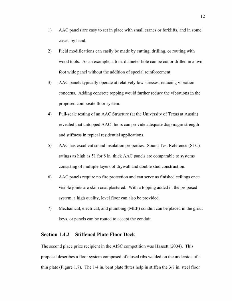
Section 1.4.2 Stiffened Plate Floor Deck
The second place prize recipient in the AISC competition was Hassett (2004). This
proposal describes a floor system composed of closed ribs welded on the underside of a
thin plate (Figure 1.7). The 1/4 in. bent plate flutes help in stiffen the 3/8 in. steel floor
13
deck. Shear flow stresses are low at the rib to plate junction, so the fillet or partial joint
penetration (PJP) welds could be a continuous or intermittent AISC minimum weld size.
The space between the ribs could accommodate electrical and plumbing conduit. The
total steel depth would be approximately 10 in. and the modules could be fabricated in 7’-
6” x 40’ units.
Figure 1.7 - Stiffened Plate Floor Deck (Hassett 2004)
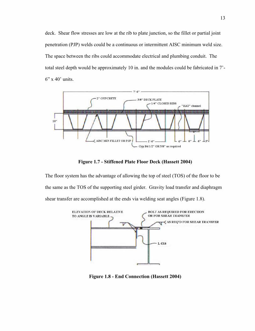
The floor system has the advantage of allowing the top of steel (TOS) of the floor to be
the same as the TOS of the supporting steel girder. Gravity load transfer and diaphragm
shear transfer are accomplished at the ends via welding seat angles (Figure 1.8).
Figure 1.8 - End Connection (Hassett 2004)
14
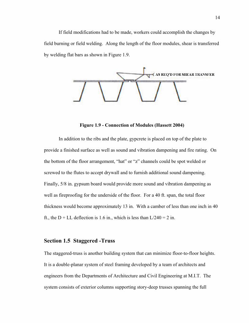
If field modifications had to be made, workers could accomplish the changes by
field burning or field welding. Along the length of the floor modules, shear is transferred
by welding flat bars as shown in Figure 1.9.
Figure 1.9 - Connection of Modules (Hassett 2004)
In addition to the ribs and the plate, gypcrete is placed on top of the plate to
provide a finished surface as well as sound and vibration dampening and fire rating. On
the bottom of the floor arrangement, “hat” or “z” channels could be spot welded or
screwed to the flutes to accept drywall and to furnish additional sound dampening.
Finally, 5/8 in. gypsum board would provide more sound and vibration dampening as
well as fireproofing for the underside of the floor. For a 40 ft. span, the total floor
thickness would become approximately 13 in. With a camber of less than one inch in 40
ft., the D + LL deflection is 1.6 in., which is less than L/240 = 2 in.
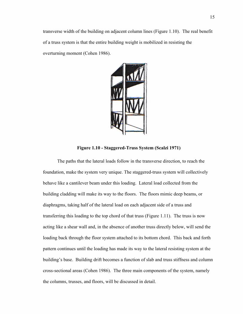
Section 1.5 Staggered -Truss
The staggered-truss is another building system that can minimize floor-to-floor heights.
It is a double-planar system of steel framing developed by a team of architects and
engineers from the Departments of Architecture and Civil Engineering at M.I.T. The
system consists of exterior columns supporting story-deep trusses spanning the full
15
transverse width of the building on adjacent column lines (Figure 1.10). The real benefit
of a truss system is that the entire building weight is mobilized in resisting the
overturning moment (Cohen 1986).
Figure 1.10 - Staggered-Truss System (Scalzi 1971)
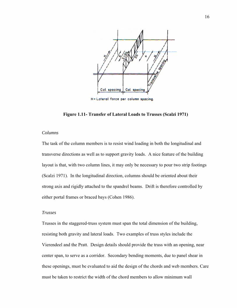
The paths that the lateral loads follow in the transverse direction, to reach the
foundation, make the system very unique. The staggered-truss system will collectively
behave like a cantilever beam under this loading. Lateral load collected from the
building cladding will make its way to the floors. The floors mimic deep beams, or
diaphragms, taking half of the lateral load on each adjacent side of a truss and
transferring this loading to the top chord of that truss (Figure 1.11). The truss is now
acting like a shear wall and, in the absence of another truss directly below, will send the
loading back through the floor system attached to its bottom chord. This back and forth
pattern continues until the loading has made its way to the lateral resisting system at the
building’s base. Building drift becomes a function of slab and truss stiffness and column
cross-sectional areas (Cohen 1986). The three main components of the system, namely
the columns, trusses, and floors, will be discussed in detail.
16
Figure 1.11- Transfer of Lateral Loads to Trusses (Scalzi 1971)
Columns
The task of the column members is to resist wind loading in both the longitudinal and
transverse directions as well as to support gravity loads. A nice feature of the building
layout is that, with two column lines, it may only be necessary to pour two strip footings
(Scalzi 1971). In the longitudinal direction, columns should be oriented about their
strong axis and rigidly attached to the spandrel beams. Drift is therefore controlled by
either portal frames or braced bays (Cohen 1986).
Trusses
Trusses in the staggered-truss system must span the total dimension of the building,
resisting both gravity and lateral loads. Two examples of truss styles include the
Vierendeel and the Pratt. Design details should provide the truss with an opening, near
center span, to serve as a corridor. Secondary bending moments, due to panel shear in
these openings, must be evaluated to aid the design of the chords and web members. Care
must be taken to restrict the width of the chord members to allow minimum wall
17
dimensions while still providing adequate bearing for the floor construction. It should be
noted that, in a simplistic sense, all truss members are subjected to axial forces only,
allowing designers to take advantage of using high strength steel members (Scalzi 1971).
In the field, the trusses are connected at both chords, thus local bending (at the
bottom chord connection) occurs in the columns. However, research has shown that this
bending is usually negligible; however, a computer analysis should verify that decision
(Scalzi 1971). Posts and hangers placed on the panel points of trusses can provide
additional loading when locations in the building prohibit the placement of a truss in the
typical staggered arrangement (Scalzi 1971).
Floors
The floor systems can consist of steel deck with infill concrete, steel joists with concrete
topping, concrete slabs, or concrete planks, provided that the system can adequately
handle the gravity and lateral loads from wind. In terms of gravity loading, the floor
systems can be modeled series of continuous spans or simple spans over two column
spacings. Code requirements may allow a reduction in the design live load because large,
clear spans are typically present.
Floor panels are also subjected to lateral loads and must exhibit enough in-plane
diaphragm strength and stiffness to transfer these lateral loads to the trusses. Direct
welding (if a steel deck is used) or welded shear plates (if concrete slabs or planks are
used) are used as shear connections to transfer the in-plane shear. In some instances, the
height of the building may be limited by the shear capacity of the floor. Mechanical
requirements may also dictate the type of floor system to be used. However, floor depths
18
can be minimized because the floor spans may be short bay lengths, providing two
column bay spacings for room arrangements (Scalzi 1971).
Section 1.6 Open-Web Steel Joist Construction
The first open-web steel joist, fabricated in 1923, was a Warren truss configuration. The
top and bottom chords were round bars with the web of the joist formed from a
continuous, bent bar. In 1928, the first specifications were adopted, and in the following
year, the first load table was introduced (SJI 2005).
Section 1.6.1 Dry Floor Construction
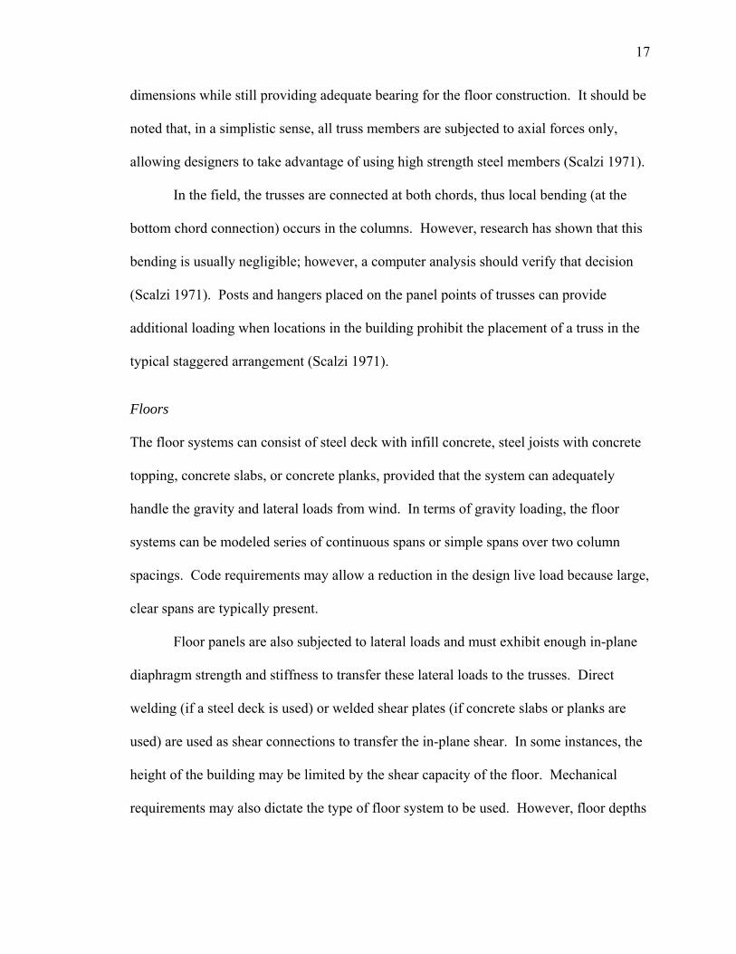
An early attempt to develop an innovative steel floor system, using open-web steel joist
to compete with flat plate concrete slab construction, was the Dry Floor system (Figure
1.12). A Dry Floor system was proposed to address problems in high-rise apartment
construction including: structural borne sound, noise transmission, impact noise, interior
partition cracking, seasonal limitations, labor-material balance, and economics. For a
quantitative description on the performance of the Dry Floor system in these categories,
refer to Newman (1966).
The steel bar joists were capable of acting compositely with the steel-edged,
gypsum planks to obtain sufficient diaphragm strength to resist lateral loads. Full scale
testing of a two-bay portion of floor area (between two column lines), in a typical
apartment building, was conducted at the U.S. Steel Applied Research Laboratory
19
Figure 1.12 - Example of Dry Floor System (Adapted from Newman (1966))
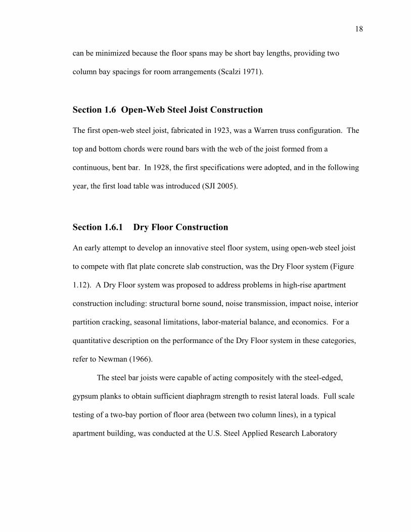
(Fang 1968). The gypsum planks used were precast units 2 in. thick, 15 in. wide, and 10
ft. long. The edges of the planks were reinforced with 22 ga. galvanized-steel tongue-
and-groove edges to form mating joints (Figure 1.13). The results of the testing
concluded that a very small magnitude of deflections resulted from the testing of the
gypsum planks in place. Furthermore, it was apparent that the gypsum deck provided
nearly all of the resistance to horizontal movement with very little shear contributed by
the stiffness of the frame (Fang 1968).
Figure 1.13 - Gypsum-Plank Details (Fang 1968)
20
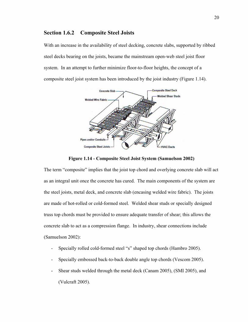
Section 1.6.2 Composite Steel Joists
With an increase in the availability of steel decking, concrete slabs, supported by ribbed
steel decks bearing on the joists, became the mainstream open-web steel joist floor
system. In an attempt to further minimize floor-to-floor heights, the concept of a
composite steel joist system has been introduced by the joist industry (Figure 1.14).
Figure 1.14 - Composite Steel Joist System (Samuelson 2002)
The term “composite” implies that the joist top chord and overlying concrete slab will act
as an integral unit once the concrete has cured. The main components of the system are
the steel joists, metal deck, and concrete slab (encasing welded wire fabric). The joists
are made of hot-rolled or cold-formed steel. Welded shear studs or specially designed
truss top chords must be provided to ensure adequate transfer of shear; this allows the
concrete slab to act as a compression flange. In industry, shear connections include
(Samuelson 2002):
- Specially rolled cold-formed steel “s” shaped top chords (Hambro 2005).
- Specially embossed back-to-back double angle top chords (Vescom 2005).
- Shear studs welded through the metal deck (Canam 2005), (SMI 2005), and
(Vulcraft 2005).
21
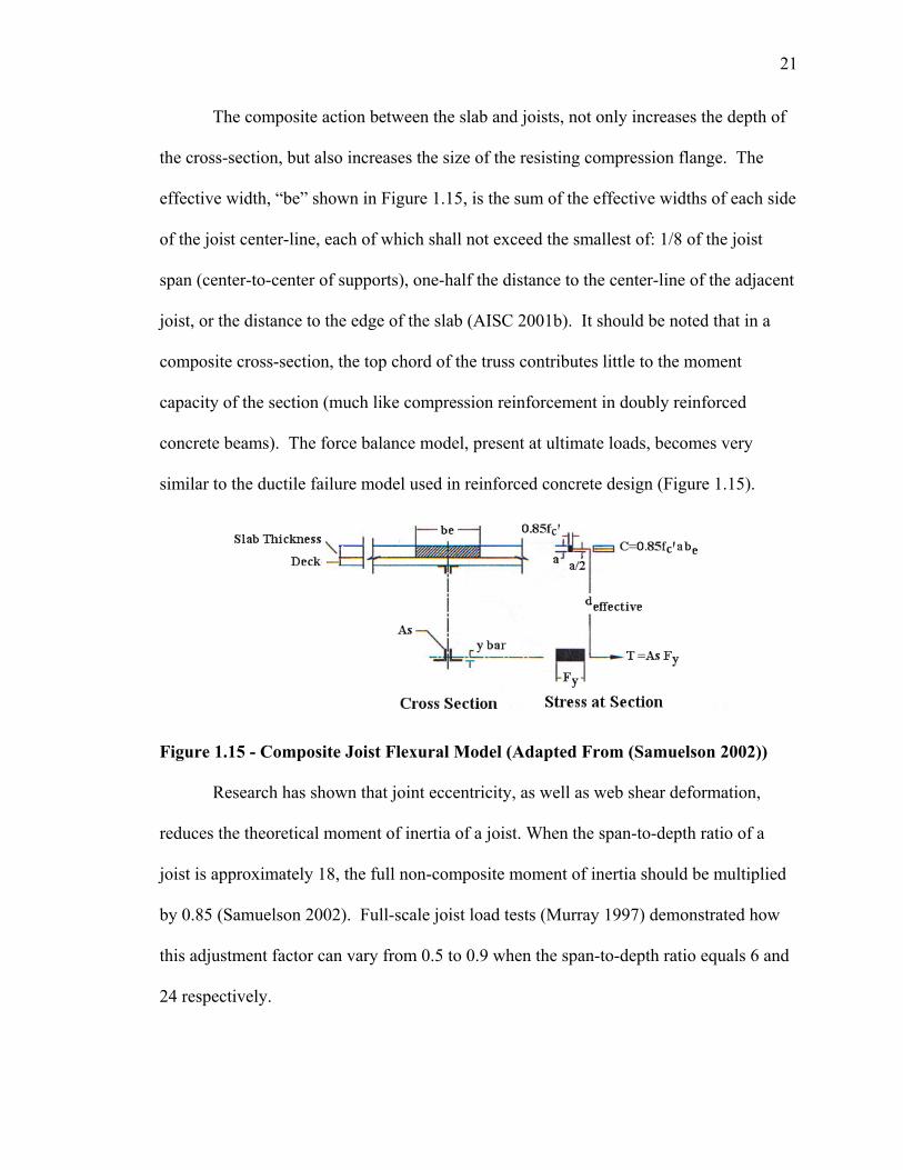
The composite action between the slab and joists, not only increases the depth of
the cross-section, but also increases the size of the resisting compression flange. The
effective width, “be” shown in Figure 1.15, is the sum of the effective widths of each side
of the joist center-line, each of which shall not exceed the smallest of: 1/8 of the joist
span (center-to-center of supports), one-half the distance to the center-line of the adjacent
joist, or the distance to the edge of the slab (AISC 2001b). It should be noted that in a
composite cross-section, the top chord of the truss contributes little to the moment
capacity of the section (much like compression reinforcement in doubly reinforced
concrete beams). The force balance model, present at ultimate loads, becomes very
similar to the ductile failure model used in reinforced concrete design (Figure 1.15).
Figure 1.15 - Composite Joist Flexural Model (Adapted From (Samuelson 2002))
Research has shown that joint eccentricity, as well as web shear deformation,
reduces the theoretical moment of inertia of a joist. When the span-to-depth ratio of a
joist is approximately 18, the full non-composite moment of inertia should be multiplied
by 0.85 (Samuelson 2002). Full-scale joist load tests (Murray 1997) demonstrated how
this adjustment factor can vary from 0.5 to 0.9 when the span-to-depth ratio equals 6 and
24 respectively.
22
Since the mid 1960’s, many research efforts have been made in testing composite
joists (Samuelson 2002). Among this list of testing includes the work of: Lembeck
(1965), Galambos (1970), Atkinson (1972), Atkinson (1972), Azmi (1972), Robinson
(1978), Leon (1987), Curry (1988), and Brattland (1992).
Quantifying the benefits of composite joists in a standardized manner is a
relatively recent task. In 1996, the ASCE Task Committee on Design Criteria for
Composite Structures in Steel and Concrete published a “Proposed Specification and
Commentary for Composite Joists and Composite Trusses (ASCE 1996).” Design topics
in this proposal include: the design of the top chord, bottom chord, web elements, and
shear connections as well as flexural capacity calculations and serviceability criteria
(Samuelson 2002). Finally, an inaugural Steel Joist Institute specification publication
date is anticipated to occur in the near future.
Depending on the type of project, benefits from choosing composite over non-
composite joists may include (Samuelson 2003):
- A more efficient and stiffer composite design makes it possible to support a given
load with a shallower joist.
- Weight savings from the joist design reduces building costs.
- Simplified erection, faster connections, and minimal crane lifts occur. With fewer
and simpler connections, ironworkers don’t have to align a large number of bolt
holes.
- Large column-free areas give tenants maximum flexibility on floor layouts.
Composite joists have been used successfully in floors with spans exceeding 100’.
23
- Customized composite joist designs can be created for any given loading and
serviceability requirements.
The two main advantages of composite construction are the high speed of
construction and the economy of composite joists at long spans. Samuelson (2003)
explained that using composite joists for spans around 35 ft. to 45 ft. or longer definitely
demonstrate economical construction.
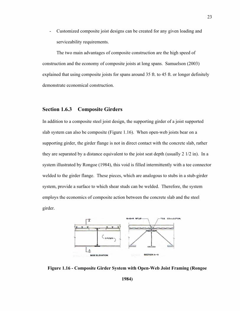
Section 1.6.3 Composite Girders
In addition to a composite steel joist design, the supporting girder of a joist supported
slab system can also be composite (Figure 1.16). When open-web joists bear on a
supporting girder, the girder flange is not in direct contact with the concrete slab, rather
they are separated by a distance equivalent to the joist seat depth (usually 2 1/2 in). In a
system illustrated by Rongoe (1984), this void is filled intermittently with a tee connector
welded to the girder flange. These pieces, which are analogous to stubs in a stub-girder
system, provide a surface to which shear studs can be welded. Therefore, the system
employs the economics of composite action between the concrete slab and the steel
girder.
Figure 1.16 - Composite Girder System with Open-Web Joist Framing (Rongoe
1984)
24
Based upon a full-scale load test load test performed at the Berlin Construction
Company, Rongoe (1984) concluded that:
- Lower floor-to-floor heights are achieved by dropping the girder depths on the
order of 4 to 6 in. for girders spans of 20-35 ft.
- Girder weights are lowered by replacing non-composite girders with composite
girders (aW18 x 35 was reduced to a W14 x 22 in this test).
- Composite action created a stiffer floor system, diminishing floor vibrations.
- A cost analysis comparing three different 30 ft. girders configurations confirmed
that a cheaper installation cost is obtained.
- Special fittings, techniques, and training workmen are not required.
- Several combinations of connectors and studs are possible to meet material,
equipment, labor, and local regulations requirements.
Section 1.7 Space Trusses
Space trusses can serve as floor systems, consisting of highly indeterminate three-
dimensional lattice networks. This type of floor system relies upon disciplined member
repetition and geometric modularity in order to span long distances in two directions.
Therefore, this system, though not as common as the other floor systems mentioned in
this report, offers a designer the opportunity to create a steel floor system that spans in
two directions.
Generally speaking, problems have become apparent with these types of
structures. In non-composite trusses, there is the possibility of brittle failure caused by
the successive buckling of a series of critical compression-chord members. A
25
progressive collapse mode of failure can be attributed to residual forces that are a result
of member lack-of-fit, experimental scatter in peak loads of compression, and the
stiffness of the member-node joints (El-Sheikh 1993). A study conducted by El-Sheikh
(1993) concluded that forming a composite concrete top chord was more effective than
providing overstrengthened top chord members in order to improve failure behavior.
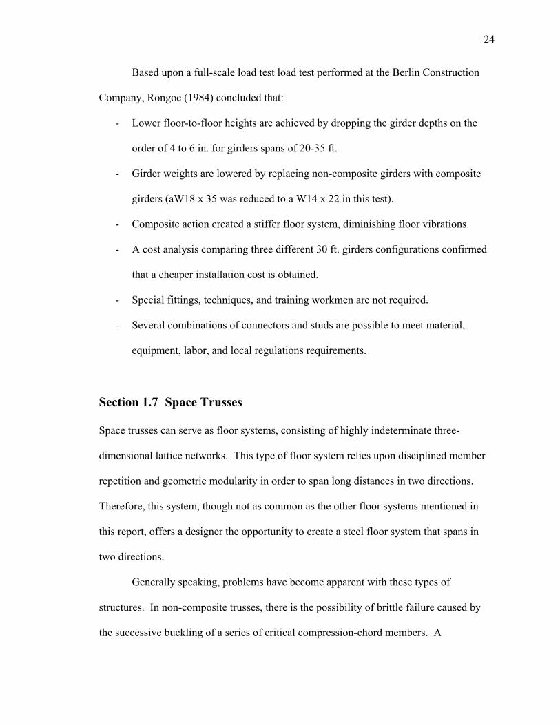
Another problem with space structures is the high cost, that results from often using
contributed by the often complicated node connectors and member end fittings in
assemblage (El-Sheikh 2000). An example of such a connection, used in the testing done
by El-Sheikh (1993), is shown in Figure 1.17.
Figure 1.17 - Example of End Fittings and Node Complexity (El-Sheikh 1993)
An innovative space truss system proposed to provide low cost and sound
structural behavior is the Catrus Space Truss (El-Sheikh 2000). Three main features of
the system’s jointing arrangement include:
- Continuous top and bottom chord members are located across the joints.
- Single bolts are used to directly bolt together the members (eliminating the use of
node connectors).
26
- Diagonal and chord members are stacked above each other, thus producing joint
eccentricity, but allowing chord member continuity.
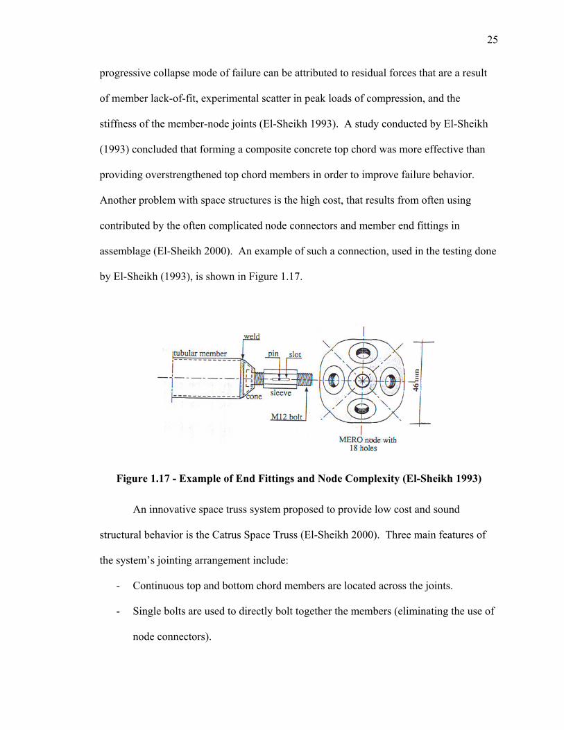
Member sections include rectangular hollow sections (top chords), flat bars (bottom
chords), and circular hollow sections (diagonal members). As shown in Figure 1.18, the
composite option has a top nut and bolt that combine to serve as a shear stud encased in a
concrete deck. Not shown is the non-composite top joint detail and an alternative deck
detail using timber boards. Benefits of this system over traditional space trusses include:
- Simple jointing using direct bolting instead of complicated node connectors
leading to an easy fabrication and erection process.
- High strength/weight and stiffness/weight ratios.
- Ductile failure.
- Adequate ability to cover areas with different sizes with flexibility of support
locations.
- Easy attachment of cladding and false ceilings.
Figure 1.18 - Top Joint Shown (Composite Option) and Member Shear Stud (El-
Sheikh 2000)
27
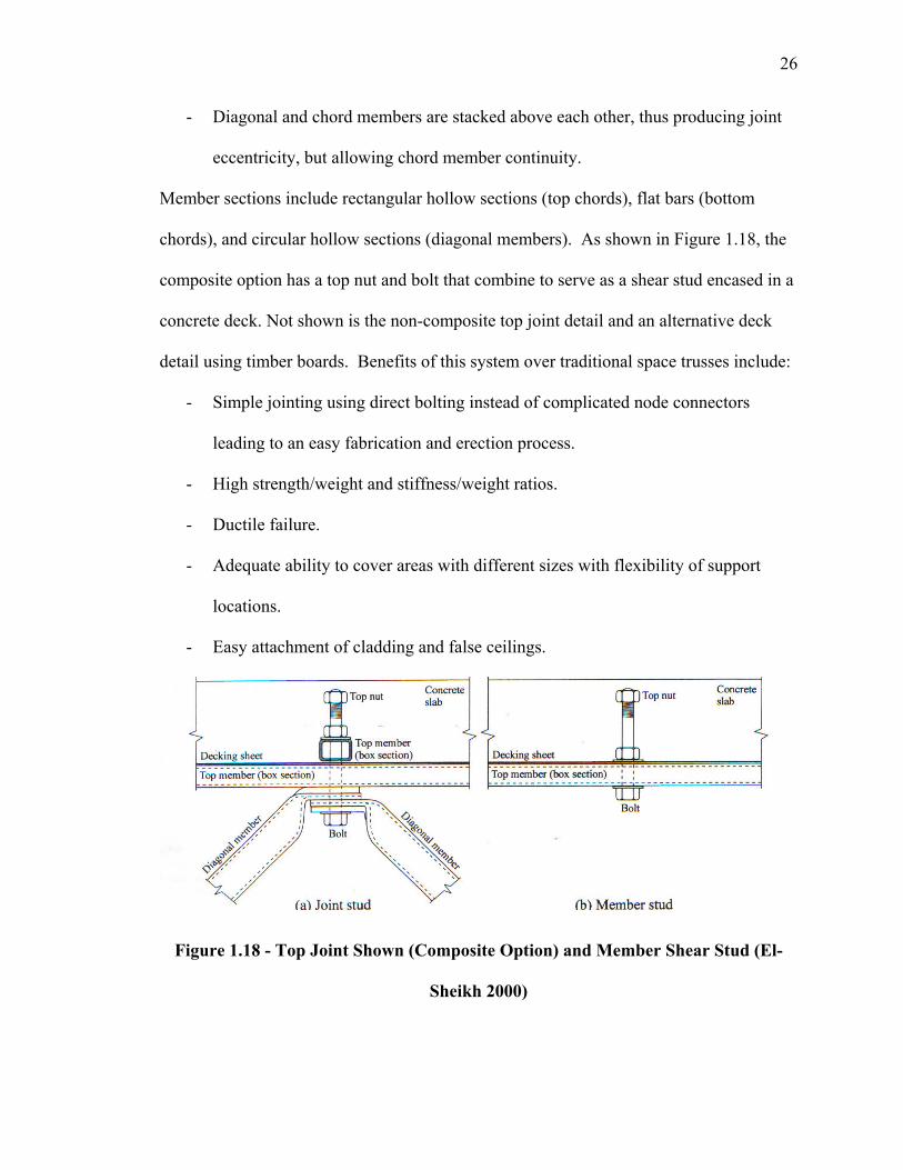
An experimental program conducted between 1994 and 1996, assessed five
different models of the Catrus system (El-Sheikh 2000). Truss models with overall
dimensions of 4 x 4 x 0.6 m were used, as shown in Figure 1.19. The results
demonstrated that the system distributed the forces away from affected areas
exceptionally well while retaining good joint stability. Noticeable sagging and top chord
deformations supplied clear, ample warning of failure in all tests. Furthermore, benefits
of composite action included higher strength and stiffness with better overall ductility.
The composite action also provided economical savings in truss top chord members,
while preventing buckling of these top members.
Figure 1.19 - Layout of Catrus Truss Model (El-Sheikh 2000)
28
Section 1.8 Synthesis of Past Literature and Direction for Present
Research
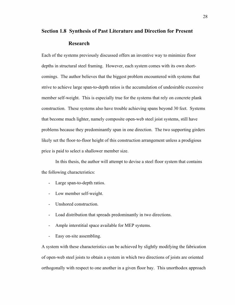
Each of the systems previously discussed offers an inventive way to minimize floor
depths in structural steel framing. However, each system comes with its own short-
comings. The author believes that the biggest problem encountered with systems that
strive to achieve large span-to-depth ratios is the accumulation of undesirable excessive
member self-weight. This is especially true for the systems that rely on concrete plank
construction. These systems also have trouble achieving spans beyond 30 feet. Systems
that become much lighter, namely composite open-web steel joist systems, still have
problems because they predominantly span in one direction. The two supporting girders
likely set the floor-to-floor height of this construction arrangement unless a prodigious
price is paid to select a shallower member size.
In this thesis, the author will attempt to devise a steel floor system that contains
the following characteristics:
- Large span-to-depth ratios.
- Low member self-weight.
- Unshored construction.
- Load distribution that spreads predominantly in two directions.
- Ample interstitial space available for MEP systems.
- Easy on-site assembling.
A system with these characteristics can be achieved by slightly modifying the fabrication
of open-web steel joists to obtain a system in which two directions of joists are oriented
orthogonally with respect to one another in a given floor bay. This unorthodox approach

29
of using steel joists results in structural behavior that allows a reduction in supporting
girder depths, which in turn reduces the floor-to-floor heights of a given story. This
thesis will show a detailed construction sequence as well the structural feasibility of the
proposed system.
30
Chapter 2 Proposed System Fabrication and Erection
Section 2.1 Introduction
Fabricating open-web steel joists is a labor-intensive assembly line process, but is
necessary to create a system in which each individual member is efficiently used. This is
especially true for the web members (round bar or crimped angles). The reduction in a
joist’s web material, compared to the amount of web material present in a rolled W-
section, for example, is significant, but comes with the price of individually welding each
web diagonal to the chord “flange” members. Through years of experience,
manufacturers have created assembly processes that have evolved, using techniques that
efficiently assemble joists. As a result, less effort is needed in the field to install joists.
The author’s goal is to continue this fabrication philosophy and take joist efficiency into a
new phase of two-way design.
The design floor bay investigated in this thesis is 30 ft. x 30 ft. with 55 psf DL
and 65 psf LL (typical office loadings). A 4 in. thick slab using 1.5 VL steel decking
(Vulcraft 2005) was selected to pass standard fire rating standards outlined in the current
steel manual (AISC 2001a). Minimizing the depth of construction within the panel was
the driving force used to select a joist configuration with an overall depth of 16 in. The
proposed system utilizes non-composite joist construction, but has promising composite
action capabilities (see chapter 4). A total of eight joists (four in each direction) are used
in the study. All joist chord members are double angles taken from cold-formed steel
shapes. The rationale behind these decisions is discussed in Chapter 3.
31
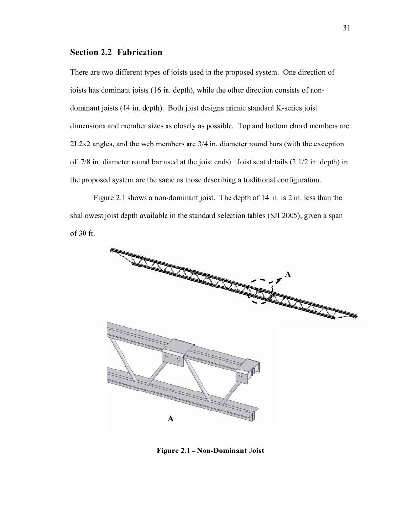
Section 2.2 Fabrication
There are two different types of joists used in the proposed system. One direction of
joists has dominant joists (16 in. depth), while the other direction consists of non-
dominant joists (14 in. depth). Both joist designs mimic standard K-series joist
dimensions and member sizes as closely as possible. Top and bottom chord members are
2L2x2 angles, and the web members are 3/4 in. diameter round bars (with the exception
of 7/8 in. diameter round bar used at the joist ends). Joist seat details (2 1/2 in. depth) in
the proposed system are the same as those describing a traditional configuration.
Figure 2.1 shows a non-dominant joist. The depth of 14 in. is 2 in. less than the
shallowest joist depth available in the standard selection tables (SJI 2005), given a span
of 30 ft.
Figure 2.1 - Non-Dominant Joist
A
A
32
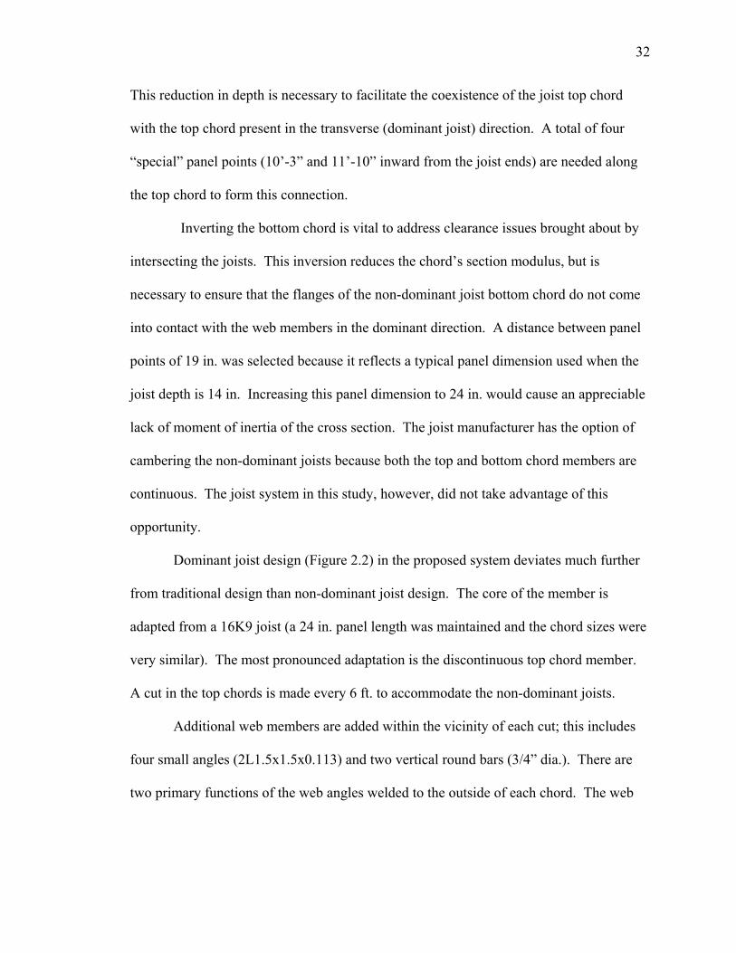
This reduction in depth is necessary to facilitate the coexistence of the joist top chord
with the top chord present in the transverse (dominant joist) direction. A total of four
“special” panel points (10’-3” and 11’-10” inward from the joist ends) are needed along
the top chord to form this connection.
Inverting the bottom chord is vital to address clearance issues brought about by
intersecting the joists. This inversion reduces the chord’s section modulus, but is
necessary to ensure that the flanges of the non-dominant joist bottom chord do not come
into contact with the web members in the dominant direction. A distance between panel
points of 19 in. was selected because it reflects a typical panel dimension used when the
joist depth is 14 in. Increasing this panel dimension to 24 in. would cause an appreciable
lack of moment of inertia of the cross section. The joist manufacturer has the option of
cambering the non-dominant joists because both the top and bottom chord members are
continuous. The joist system in this study, however, did not take advantage of this
opportunity.
Dominant joist design (Figure 2.2) in the proposed system deviates much further
from traditional design than non-dominant joist design. The core of the member is
adapted from a 16K9 joist (a 24 in. panel length was maintained and the chord sizes were
very similar). The most pronounced adaptation is the discontinuous top chord member.
A cut in the top chords is made every 6 ft. to accommodate the non-dominant joists.
Additional web members are added within the vicinity of each cut; this includes
four small angles (2L1.5x1.5x0.113) and two vertical round bars (3/4” dia.). There are
two primary functions of the web angles welded to the outside of each chord. The web
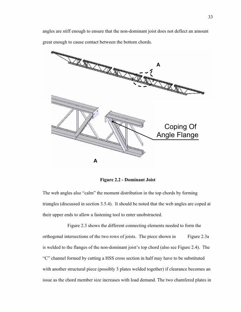
33
angles are stiff enough to ensure that the non-dominant joist does not deflect an amount
great enough to cause contact between the bottom chords.
Figure 2.2 - Dominant Joist
The web angles also “calm” the moment distribution in the top chords by forming
triangles (discussed in section 3.5.4). It should be noted that the web angles are coped at
their upper ends to allow a fastening tool to enter unobstructed.
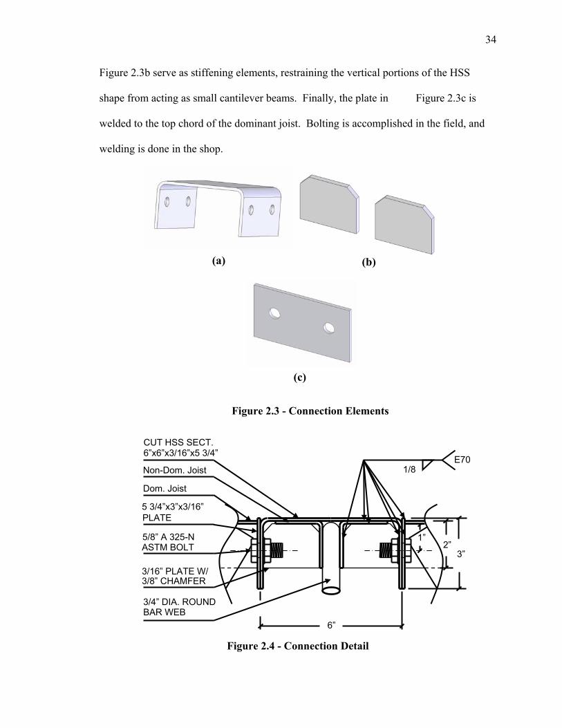
Figure 2.3 shows the different connecting elements needed to form the
orthogonal intersections of the two rows of joists. The piece shown in Figure 2.3a
is welded to the flanges of the non-dominant joist’s top chord (also see Figure 2.4). The
“C” channel formed by cutting a HSS cross section in half may have to be substituted
with another structural piece (possibly 3 plates welded together) if clearance becomes an
issue as the chord member size increases with load demand. The two chamfered plates in
A
A
Coping Of Angle Flange
34
Figure 2.3b serve as stiffening elements, restraining the vertical portions of the HSS
shape from acting as small cantilever beams. Finally, the plate in Figure 2.3c is
welded to the top chord of the dominant joist. Bolting is accomplished in the field, and
welding is done in the shop.
Figure 2.3 - Connection Elements
Figure 2.4 - Connection Detail
(a) (b)
(c)
6”
2”
CUT HSS SECT. 6”x6”x3/16”x5 3/4”
PLATE 5/8” A 325-N ASTM BOLT
3/16” PLATE W/ 3/8” CHAMFER 3/4” DIA. ROUND BAR WEB
3”
1”
E701/8
5 3/4”x3”x3/16”
Non-Dom. Joist
Dom. Joist
35
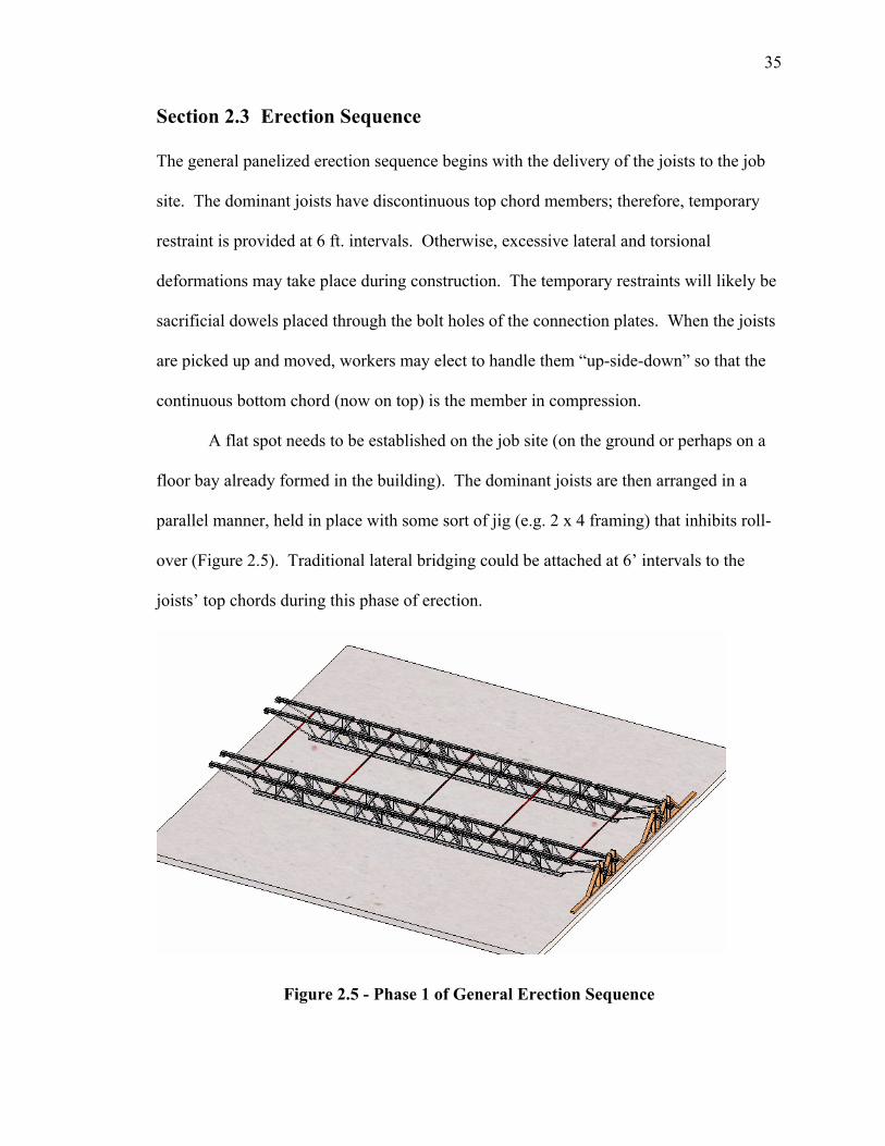
Section 2.3 Erection Sequence
The general panelized erection sequence begins with the delivery of the joists to the job
site. The dominant joists have discontinuous top chord members; therefore, temporary
restraint is provided at 6 ft. intervals. Otherwise, excessive lateral and torsional
deformations may take place during construction. The temporary restraints will likely be
sacrificial dowels placed through the bolt holes of the connection plates. When the joists
are picked up and moved, workers may elect to handle them “up-side-down” so that the
continuous bottom chord (now on top) is the member in compression.
A flat spot needs to be established on the job site (on the ground or perhaps on a
floor bay already formed in the building). The dominant joists are then arranged in a
parallel manner, held in place with some sort of jig (e.g. 2 x 4 framing) that inhibits roll-
over (Figure 2.5). Traditional lateral bridging could be attached at 6’ intervals to the
joists’ top chords during this phase of erection.
Figure 2.5 - Phase 1 of General Erection Sequence
36
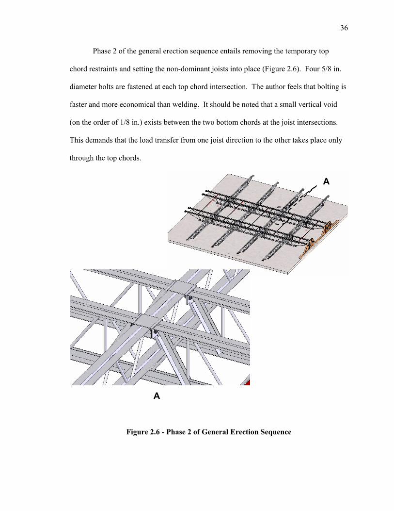
Phase 2 of the general erection sequence entails removing the temporary top
chord restraints and setting the non-dominant joists into place (Figure 2.6). Four 5/8 in.
diameter bolts are fastened at each top chord intersection. The author feels that bolting is
faster and more economical than welding. It should be noted that a small vertical void
(on the order of 1/8 in.) exists between the two bottom chords at the joist intersections.
This demands that the load transfer from one joist direction to the other takes place only
through the top chords.
Figure 2.6 - Phase 2 of General Erection Sequence
A
A
37
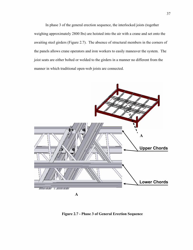
In phase 3 of the general erection sequence, the interlocked joists (together
weighing approximately 2800 lbs) are hoisted into the air with a crane and set onto the
awaiting steel girders (Figure 2.7). The absence of structural members in the corners of
the panels allows crane operators and iron workers to easily maneuver the system. The
joist seats are either bolted or welded to the girders in a manner no different from the
manner in which traditional open-web joists are connected.
Figure 2.7 - Phase 3 of General Erection Sequence
A
A
Upper Chords
Lower Chords
38
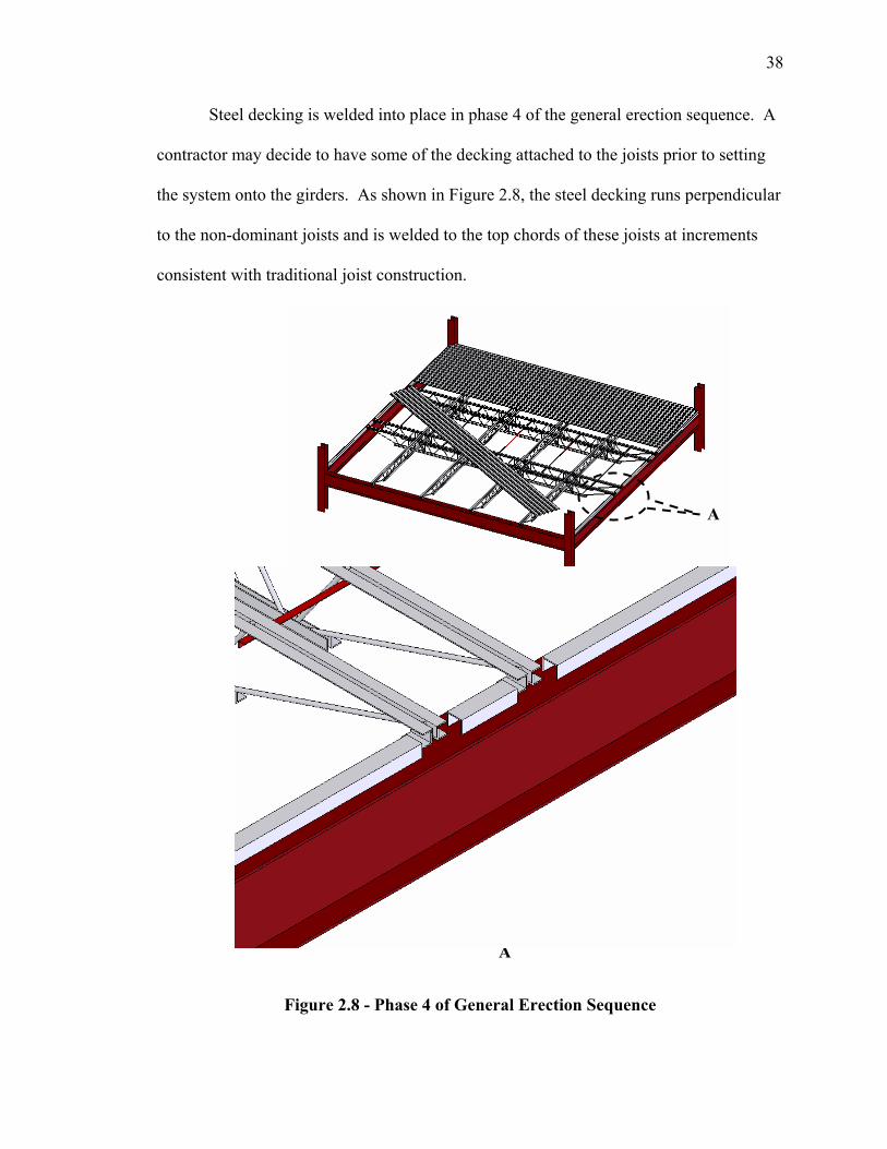
Steel decking is welded into place in phase 4 of the general erection sequence. A
contractor may decide to have some of the decking attached to the joists prior to setting
the system onto the girders. As shown in Figure 2.8, the steel decking runs perpendicular
to the non-dominant joists and is welded to the top chords of these joists at increments
consistent with traditional joist construction.
Figure 2.8 - Phase 4 of General Erection Sequence
A
A
39
The decking will “bubble-up” a small amount in the vertical direction at the joist
intersections due to the presence of the connection elements. This misalignment,
equivalent to the thickness of the HSS piece (3/16 in.), is assumed to be negligible in the
design.
Direct contact is assumed to be non-existent between the dominant joists and the
decking. In other words, the dominant joists only receive loading via the top chord
connections to the non-dominant joists. Note that the steel decking in Figure 2.8 is
shown to be terminated at the girders. The figure is illustrated in this manner for clarity.
In actuality, the deck is continuous over the girders because the panel is located in an
interior bay.
The proposed system uses the girders (which run parallel to the non-dominant
joists) to directly carry some of the decking. In other words, each of these girders will
have point loads from dominant joist reactions as well as uniform line loading from a 6 ft.
tributary width of deck (assuming that a symmetrical adjacent bay is present). To
facilitate the bearing of the deck, a small steel shape with a depth of 2 1/2 in. (to match
the depth of the joist seat) needs to be welded to the top of the girder. A cold-formed
steel channel is shown in Figure 2.8, but a variety of options are available depending on
the contractor’s preference. The type of detail used depends on whether or not the girders
are designed for composite construction. If composite construction is desired, using a
structural tee (Rongoe 1984) may be preferred to provide a more direct load path
(through the stem of the tee) from the shear stud to the girder flange.
Similar to a traditional system, the girders occupying the orthogonal column line
do not directly carry the steel decking. Due to the load distribution of the system, these
40
girders (running parallel to the dominant joists) will be smaller than the girders in the
other direction. If a member is needed to fill the void between the girder flange and the
deck (such would be the case if a bearing wall was placed directly over the girder), a
concrete pour stop detail could be used (detailed no differently than a traditional system).
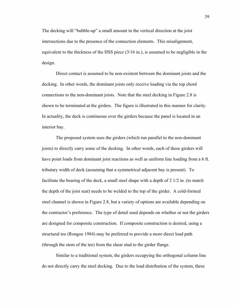
The final phase of the general construction sequence is shown in Figure 2.9. A
mat of welded wire fabric is set into place and a 4 in. concrete slab is poured over the
decking. Normal-weight concrete was assumed in the design of the proposed system.
Figure 2.9 - Phase 5 of General Erection Sequence
A
A
41
Chapter 3 Structural Behavior Section 3.1 Introduction
This chapter begins with an overview of concepts drawn from basic plate theory, and
later sections compare and contrast the behavior of the proposed two-way floor system
with the structural behavior of a two-way plate and a traditional one-way joist system.
The reader is then guided through the detailed process of arriving at the final proposed
floor system. This entails sifting through preliminary panel configurations, creating a FE
model, sizing joist members using the current specification (SJI 2005), and producing a
sufficient connection design. The influence of the joist arrangement on the supporting
steel girders is also illustrated.
Section 3.2 Plate Bending
In order to gain an understanding of the load distribution in a two-way steel floor system,
a brief derivation, accompanied by a numerical example, using classical thin-plate theory
is provided. In effect, a plate is a two-dimensional beam having bending about two in-
plane axes with twisting moment. The plate analysis provided uses expressions
consistent with Kirchoff’s plate theory of bending for isotropic, homogeneous, thin
plates. Fenster (2003) outlines the assumptions as follows:
1) The deflection of the midsurface is small in comparison with the thickness of the
plate. The slope of the deflected surface is much less than unity.
2) Straight lines initially normal to the midsurface remain straight and normal to that
surface subsequent to bending. Therefore, deflection is associated only with
42
normal bending strains.
3) No midsurface straining, in-plane straining, stretching, or contracting occurs as a
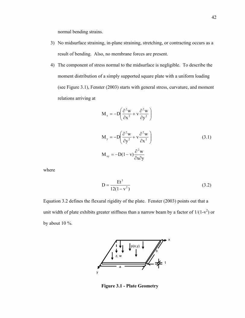
result of bending. Also, no membrane forces are present.
4) The component of stress normal to the midsurface is negligible. To describe the
moment distribution of a simply supported square plate with a uniform loading
(see Figure 3.1), Fenster (2003) starts with general stress, curvature, and moment
relations arriving at
⎟⎟⎠
⎞⎜⎜⎝
⎛∂∂
+∂∂
−= 2
2
2
2
x ywv
xwDM
⎟⎟⎠
⎞⎜⎜⎝
⎛∂∂
+∂∂
−= 2
2
2
2
y xwv
ywDM (3.1)
yxwv)D(1M
2
xy ∂∂∂
−−=
where
)v12(1EtD 2
3
−= (3.2)
Equation 3.2 defines the flexural rigidity of the plate. Fenster (2003) points out that a
unit width of plate exhibits greater stiffness than a narrow beam by a factor of 1/(1-v2) or
by about 10 %.
Figure 3.1 - Plate Geometry
a
bz, w
y
x
p(x,y)
t
43
After further tedious mathematical derivations, Fenster (2003) goes on to provide an
equation for the deflection of the plate’s surface described as
[ ] bynsin
axmsin
)/((m/a)
pπ
1w1m 1n
222
mn4
ππ∑∑∞
=
∞
= +=
bnD (3.3)
where
dydxb
ynπsina
xmπy)sinp(x,ab4p
b
0
a
0mn ∫ ∫= (3.4)
However, for a uniform load po, equation 3.4 reduces to
otherwise.,0p
odd;nm,,mnπ
16pp
mn
2o
mn
=
= (3.5)
Substituting this expression into equation Eq. 3.3, and realizing that pmn = 0 for even
values of m and n, gives the deflection
[ ]∑∑∞ ∞
=+
=m n
2226o 1,3,5,...nm,
(n/b)(m/a)mn
y/b)x/a)sin(nπsin(mπDπ
16pw (3.6)
Finally, expressions for the moments Mx and My can be formulated by substituting Eq.
3.6 into 3.1 resulting in
[ ] byn
axm
bnammnbnvamp
Mm n
ox
πππ
sinsin)/()/()/()/(16
222
22
4 ∑∑∞ ∞
+
+=
[ ] byn
axm
bnammnbnamvp
Mm n
oy
πππ
sinsin)/()/()/()/(16
222
22
4 ∑∑∞ ∞
+
+= (3.7)
1,3,5,...nm,for =
It should be noted that Eq. 3.6 will converge more rapidly than Eq. 3.7. Fenster
(2003) notes that after only four terms, the maximum deflection (located at midspan of
the plate) is wmax = 0.0443 po(a4/Et3). Another author (Boresi 1993) tabulates the
44
coefficient of this equation as C = 0.047. Boresi (1993) comments that this coefficient is
reduced to C = 0.016 when the edge restraints are clamped (i.e. the deflection of the
center of a clamped plate is about one third of the value found for a plate with simply
supported edges). In terms of moment at midspan, Boresi (1993) shows a Mclamped value
≈ 40% less than that of a simply supported plate.
In order to gain a feel for how the moment distribution varies over a slice of
simply supported square plate, consider the following input for a steel plate.
a = 360 in b = 360 in
v = .3 E = 29,000,000 psi t = 6 in
po = 2.5347 psi (sum of 120 psf super-imposed loading and 245 psf self-weight)
Using Eq. 3.7, allowing x to vary from 0 to 360 in. while holding y constant at 180 in.,
the distribution of Mx is show in Figure 3.2. The solution was obtained after truncating
the series at m and n equal to 11 (recall that only the odd terms are used) resulting in a
percent difference of 0.6% when compared to mid-span moment with m and n equal to 9.
The maximum moment is determined to be 0.0479 poa2 which, when taken over a unit
width, is notably less than the Mmax = 1/8 (w/2)l2 = 0.0625wl2 if only bending were
present. This illustrates that the twisting moments relieve the orthogonal axis bending
moments by approximately 25% (Nilson 1991). Upon studying the distribution in Figure
3.2, it becomes apparent that the majority of the moment resistance supplied by the plate
comes from the middle half of the plate. The moment only drops by 19% within this
middle portion. The remaining half of the plate (the two outer portions) carries less of
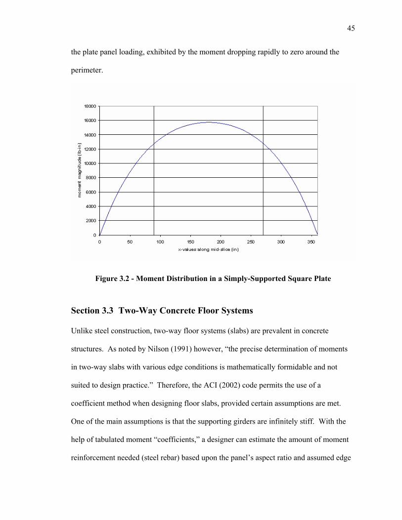
45
the plate panel loading, exhibited by the moment dropping rapidly to zero around the
perimeter.
Figure 3.2 - Moment Distribution in a Simply-Supported Square Plate
Section 3.3 Two-Way Concrete Floor Systems
Unlike steel construction, two-way floor systems (slabs) are prevalent in concrete
structures. As noted by Nilson (1991) however, “the precise determination of moments
in two-way slabs with various edge conditions is mathematically formidable and not
suited to design practice.” Therefore, the ACI (2002) code permits the use of a
coefficient method when designing floor slabs, provided certain assumptions are met.
One of the main assumptions is that the supporting girders are infinitely stiff. With the
help of tabulated moment “coefficients,” a designer can estimate the amount of moment
reinforcement needed (steel rebar) based upon the panel’s aspect ratio and assumed edge
46
restraints. The coefficients are based on elastic analysis, but also account for inelastic
redistribution (Nilson 1991). Therefore, the design moment is smaller than the elastic
maximum moment (by an appropriate amount) in a given direction. For example, in the
case of a simply supported square slab, the method allows a design moment of 0.036wl2.
That’s 25% less than the actual theoretical elastic maximum moment discussed earlier.
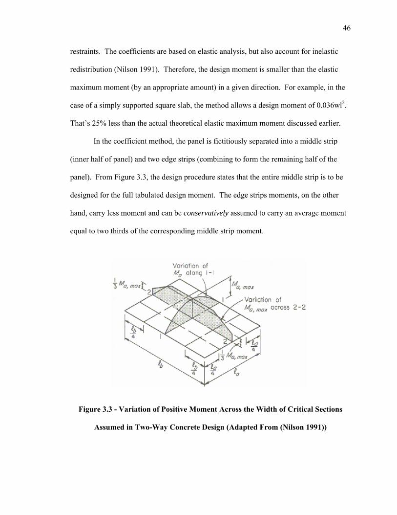
In the coefficient method, the panel is fictitiously separated into a middle strip
(inner half of panel) and two edge strips (combining to form the remaining half of the
panel). From Figure 3.3, the design procedure states that the entire middle strip is to be
designed for the full tabulated design moment. The edge strips moments, on the other
hand, carry less moment and can be conservatively assumed to carry an average moment
equal to two thirds of the corresponding middle strip moment.
Figure 3.3 - Variation of Positive Moment Across the Width of Critical Sections
Assumed in Two-Way Concrete Design (Adapted From (Nilson 1991))
47
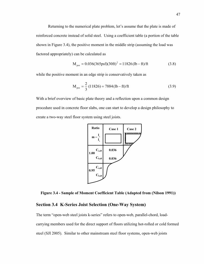
Returning to the numerical plate problem, let’s assume that the plate is made of
reinforced concrete instead of solid steel. Using a coefficient table (a portion of the table
shown in Figure 3.4), the positive moment in the middle strip (assuming the load was
factored appropriately) can be calculated as
ft)/ft(lb11826sf)(30ft)0.036(365pM 2pos −== (3.8)
while the positive moment in an edge strip is conservatively taken as
ft)/ft(lb788411826)(32M pos −== (3.9)
With a brief overview of basic plate theory and a reflection upon a common design
procedure used in concrete floor slabs, one can start to develop a design philosophy to
create a two-way steel floor system using steel joists.
Figure 3.4 - Sample of Moment Coefficient Table (Adapted from (Nilson 1991))
Section 3.4 K-Series Joist Selection (One-Way System)
The term “open-web steel joists k-series” refers to open-web, parallel-chord, load-
carrying members used for the direct support of floors utilizing hot-rolled or cold formed
steel (SJI 2005). Similar to other mainstream steel floor systems, open-web joists
Ratio
b
a
llm =
Case 1 Case 2
1.00 Ca,dl Cb,dl
0.036
0.036
0.95 Ca,dl Cb,dl
48
predominantly span in one direction. The selection of appropriate member sizes is a
process that has been highly refined by joist manufactures. For example, manufactures
can pick from a group of cold-formed angles varying in increments on the order of 1/64
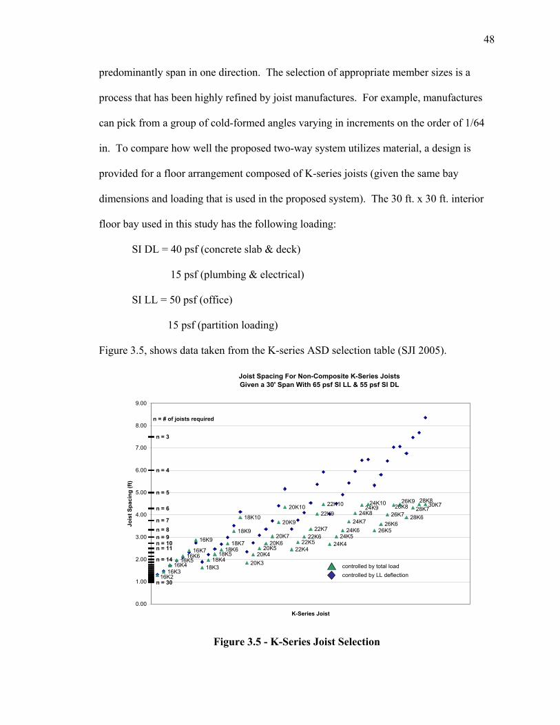
in. To compare how well the proposed two-way system utilizes material, a design is
provided for a floor arrangement composed of K-series joists (given the same bay
dimensions and loading that is used in the proposed system). The 30 ft. x 30 ft. interior
floor bay used in this study has the following loading:
SI DL = 40 psf (concrete slab & deck)
15 psf (plumbing & electrical)
SI LL = 50 psf (office)
15 psf (partition loading)
Figure 3.5, shows data taken from the K-series ASD selection table (SJI 2005).
Joist Spacing For Non-Composite K-Series JoistsGiven a 30' Span With 65 psf SI LL & 55 psf SI DL
16K316K4
16K616K7
16K9
18K318K4
18K518K6
18K7
18K9
18K10
20K320K4
20K520K6
20K7
20K9
20K10
22K422K5
22K622K7
22K9
22K10
24K424K5
24K624K7
24K8
26K526K6
26K7 28K6
n = 14
n = 11n = 10n = 9n = 8n = 7
n = 6
n = 5
n = 4
n = 3
n = 30
30K724K1024K9 26K8
26K928K7
28K8
16K2
16K5
0.00
1.00
2.00
3.00
4.00
5.00
6.00
7.00
8.00
9.00
K-Series Joist
Jois
t Spa
cing
(ft)
n = # of joists required
controlled by total loadcontrolled by LL deflection
Figure 3.5 - K-Series Joist Selection
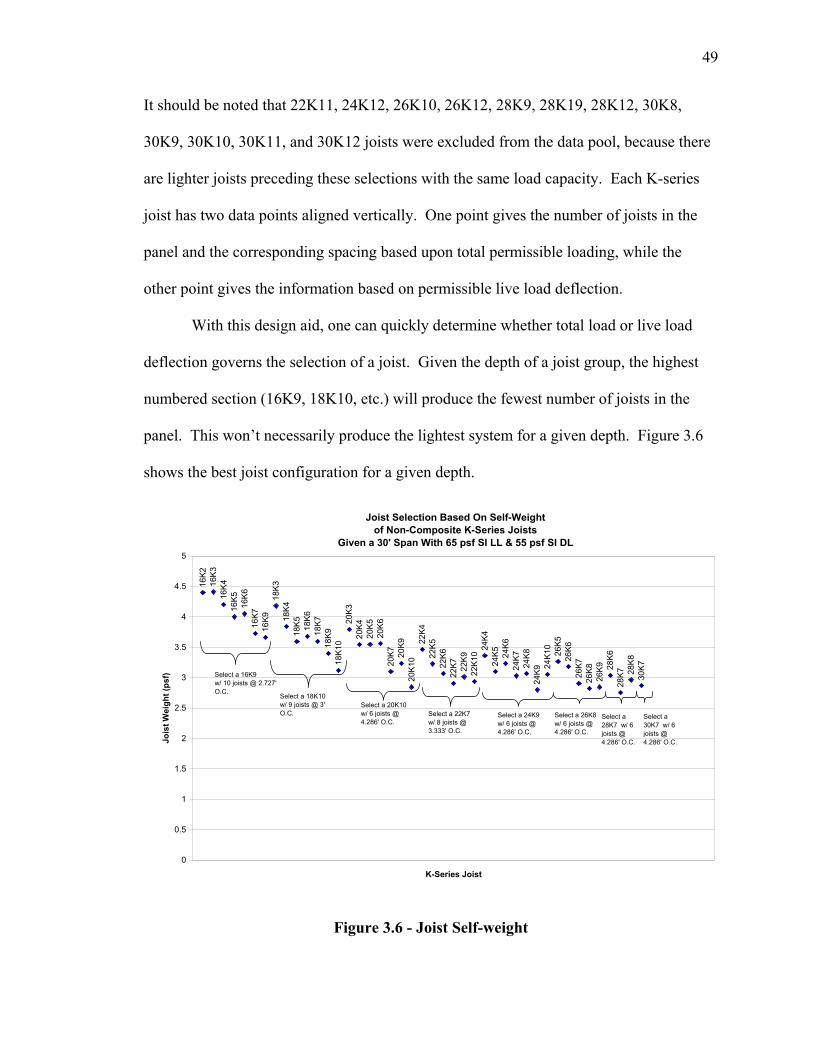
49
It should be noted that 22K11, 24K12, 26K10, 26K12, 28K9, 28K19, 28K12, 30K8,
30K9, 30K10, 30K11, and 30K12 joists were excluded from the data pool, because there
are lighter joists preceding these selections with the same load capacity. Each K-series
joist has two data points aligned vertically. One point gives the number of joists in the
panel and the corresponding spacing based upon total permissible loading, while the
other point gives the information based on permissible live load deflection.
With this design aid, one can quickly determine whether total load or live load
deflection governs the selection of a joist. Given the depth of a joist group, the highest
numbered section (16K9, 18K10, etc.) will produce the fewest number of joists in the
panel. This won’t necessarily produce the lightest system for a given depth. Figure 3.6
shows the best joist configuration for a given depth.
Joist Selection Based On Self-Weightof Non-Composite K-Series Joists
Given a 30' Span With 65 psf SI LL & 55 psf SI DL
16K2
16K
316
K416
K516
K616
K716
K918
K3
18K4
18K5 18
K618
K7
18K9
18K1
020
K320
K420
K5
20K
620
K7 20K9
20K1
022
K422
K522
K622
K7 22K9
22K1
024
K424
K5 24K6
24K7
24K8
24K9
24K1
026
K526
K626
K726
K826
K9 28K
628
K7 28K
830
K7
0
0.5
1
1.5
2
2.5
3
3.5
4
4.5
5
K-Series Joist
Jois
t Wei
ght (
psf) Select a 16K9
w/ 10 joists @ 2.727' O.C.
Select a 18K10w/ 9 joists @ 3' O.C.
Select a 20K10w/ 6 joists @ 4.286' O.C.
Select a 22K7 w/ 8 joists @ 3.333' O.C.
Select a 24K9 w/ 6 joists @ 4.286' O.C.
Select a 26K8 w/ 6 joists @ 4.286' O.C.
Select a 28K7 w/ 6 joists @ 4.286' O.C.
Select a 30K7 w/ 6 joists @ 4.286' O.C.
Figure 3.6 - Joist Self-weight
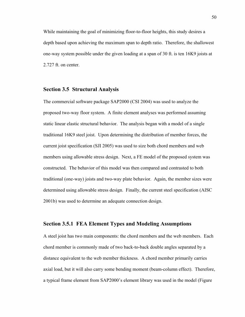
50
While maintaining the goal of minimizing floor-to-floor heights, this study desires a
depth based upon achieving the maximum span to depth ratio. Therefore, the shallowest
one-way system possible under the given loading at a span of 30 ft. is ten 16K9 joists at
2.727 ft. on center.
Section 3.5 Structural Analysis
The commercial software package SAP2000 (CSI 2004) was used to analyze the
proposed two-way floor system. A finite element analyses was performed assuming
static linear elastic structural behavior. The analysis began with a model of a single
traditional 16K9 steel joist. Upon determining the distribution of member forces, the
current joist specification (SJI 2005) was used to size both chord members and web
members using allowable stress design. Next, a FE model of the proposed system was
constructed. The behavior of this model was then compared and contrasted to both
traditional (one-way) joists and two-way plate behavior. Again, the member sizes were
determined using allowable stress design. Finally, the current steel specification (AISC
2001b) was used to determine an adequate connection design.
Section 3.5.1 FEA Element Types and Modeling Assumptions
A steel joist has two main components: the chord members and the web members. Each
chord member is commonly made of two back-to-back double angles separated by a
distance equivalent to the web member thickness. A chord member primarily carries
axial load, but it will also carry some bending moment (beam-column effect). Therefore,
a typical frame element from SAP2000’s element library was used in the model (Figure
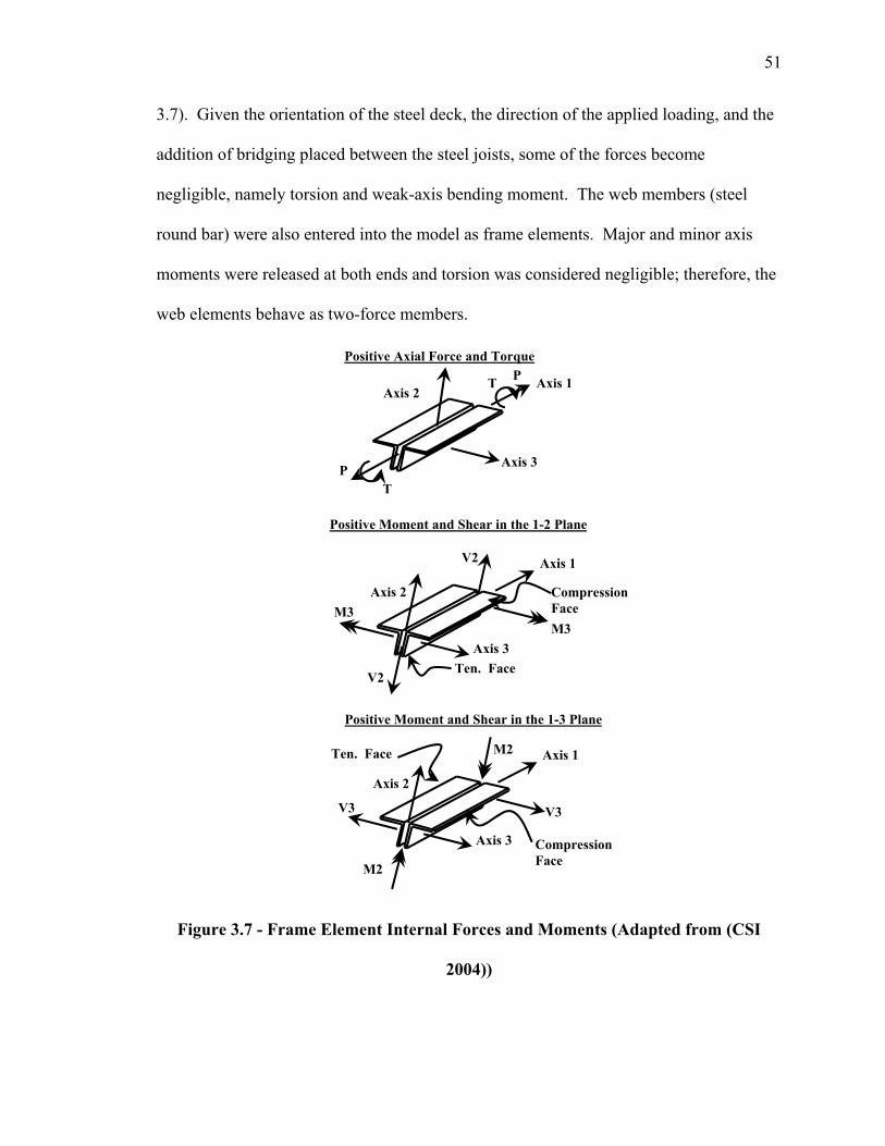
51
3.7). Given the orientation of the steel deck, the direction of the applied loading, and the
addition of bridging placed between the steel joists, some of the forces become
negligible, namely torsion and weak-axis bending moment. The web members (steel
round bar) were also entered into the model as frame elements. Major and minor axis
moments were released at both ends and torsion was considered negligible; therefore, the
web elements behave as two-force members.
Figure 3.7 - Frame Element Internal Forces and Moments (Adapted from (CSI
2004))
Positive Moment and Shear in the 1-3 Plane
Positive Axial Force and Torque
Axis 2
Axis 3
Axis 1 P T
T P
Axis 2
V2 Axis 1
Compression Face M3
Axis 3
V2
M3
Ten. Face
Positive Moment and Shear in the 1-2 Plane
Axis 2
M2 Axis 1
Compression Face
V3
Axis 3
M2
V3
Ten. Face
52
As with any finite element model, consideration of the discretization of a system
needs to be addressed. For convenience, all elements between panel points in the models
were further divided by the same amount. The author believes that dividing the chord
members between panel points into 16 elements (equating to 1.5 in. and 2.125 in.
elements for 24 in. and 34 in. panel lengths respectively) is sufficient to capture the
appropriate distribution of bending moment. Further effort in studying the accuracy of
the convergence of a more refined mesh is unwarranted because of other assumptions
built into the model. Web members, carrying only axial load, were comprised of only
one element.
Section 3.5.2 Traditional Joist Analysis and Results
Open-web joist design makes use of very slender angles; therefore, acknowledging
different buckling modes of the top chord becomes important. There are three possible
axes about which a single angle can buckle (Figure 3.8).
Figure 3.8 - Axes about Which Buckling Can Occur
The attachment of the deck to the joist’s top chord plays a critical role in determining
which buckling mode will control. The current joist specification (SJI 2005) section 5.8e
states that the spacing for deck attachments along the top chord shall not exceed 36 in. In
Xbar
Ybar
Z
Z
X X
Y
Y
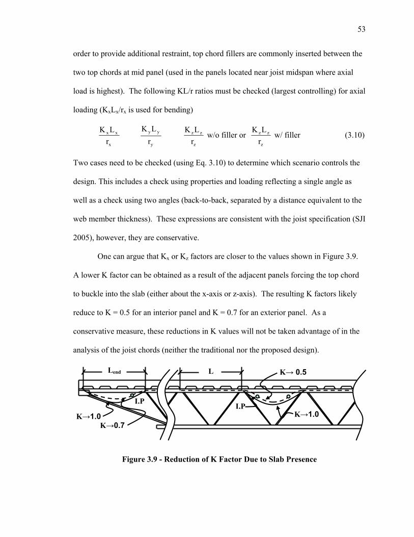
53
order to provide additional restraint, top chord fillers are commonly inserted between the
two top chords at mid panel (used in the panels located near joist midspan where axial
load is highest). The following KL/r ratios must be checked (largest controlling) for axial
loading (KxLx/rx is used for bending)
x
xx
rLK
y
yy
rLK
z
zz
rLK w/o filler or
z
zz
rLK w/ filler (3.10)
Two cases need to be checked (using Eq. 3.10) to determine which scenario controls the
design. This includes a check using properties and loading reflecting a single angle as
well as a check using two angles (back-to-back, separated by a distance equivalent to the
web member thickness). These expressions are consistent with the joist specification (SJI
2005), however, they are conservative.
One can argue that Kx or Kz factors are closer to the values shown in Figure 3.9.
A lower K factor can be obtained as a result of the adjacent panels forcing the top chord
to buckle into the slab (either about the x-axis or z-axis). The resulting K factors likely
reduce to K = 0.5 for an interior panel and K = 0.7 for an exterior panel. As a
conservative measure, these reductions in K values will not be taken advantage of in the
analysis of the joist chords (neither the traditional nor the proposed design).
Figure 3.9 - Reduction of K Factor Due to Slab Presence
K→1.0
L
K→1.0
K→ 0.5
I.P I.P
Lend
K→0.7
54
Following the specification (SJI 2005), the following ASD equations were used to
determine the adequacy of the web members. It should be noted that these equations
were designed for hot rolled steel shapes. However, most joist manufactures make use of
cold-formed shapes because the member thickness increments are smaller. To avoid
deviating into all the design idiosyncrasies that come from cold-formed steel design, it is
assumed that the chord member design (though using member sizes reflecting cold-
formed steel shapes) can be accomplished by using “hot-rolled” equations.
The ASD equations governing axial loading are as follows:
fa ≤ Fa = 0.6 Fy (Tension Members) (3.11)
yF
QF
aa F0.6580.6QFf e
y
⎥⎥
⎦
⎤
⎢⎢
⎣
⎡=≤
⎟⎟⎠
⎞⎜⎜⎝
⎛
(Comp. Members) (3.12)
where
fa = applied axial stress
Fa = allowable axial stress
Fy = yield stress (50 ksi)
Q = form factor (= 1 for round bar)
Fe = elastic buckling stress 2
2
rKL
Eπ
⎟⎟⎠
⎞⎜⎜⎝
⎛
The ASD equations for the chord members (beam columns) become
at the panel point: fa + fb ≤ 0.6 Fy (3.13)
at the mid panel for (fa/Fa ≥ 0.2) :
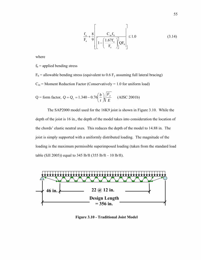
55
1.0QF
F1.67f
1
fC98
Ff
be
a
bm
a
a ≤
⎥⎥⎥⎥⎥
⎦
⎤
⎢⎢⎢⎢⎢
⎣
⎡
⎥⎦
⎤⎢⎣
⎡⎟⎟⎠
⎞⎜⎜⎝
⎛−
+ (3.14)
where
fb = applied bending stress
Fb = allowable bending stress (equivalent to 0.6 Fy assuming full lateral bracing)
Cm = Moment Reduction Factor (Conservatively = 1.0 for uniform load)
Q = form factor, EF
tbQQ y
s ⎟⎠⎞
⎜⎝⎛−== 76.0340.1 (AISC 2001b)
The SAP2000 model used for the 16K9 joist is shown in Figure 3.10. While the
depth of the joist is 16 in., the depth of the model takes into consideration the location of
the chords’ elastic neutral axes. This reduces the depth of the model to 14.88 in. The
joist is simply supported with a uniformly distributed loading. The magnitude of the
loading is the maximum permissible superimposed loading (taken from the standard load
table (SJI 2005)) equal to 345 lb/ft (355 lb/ft – 10 lb/ft).
Figure 3.10 - Traditional Joist Model
Design Length = 356 in.
22 @ 12 in. 46 in.
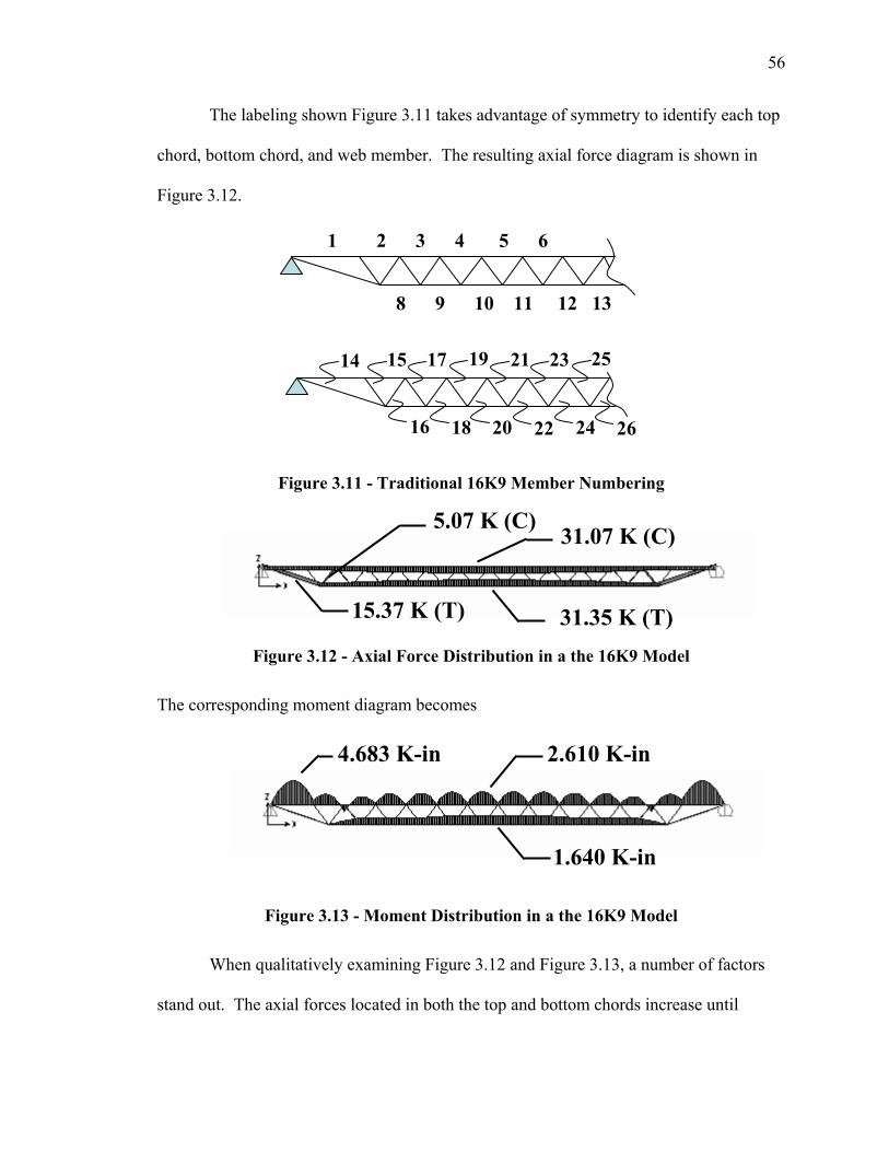
56
The labeling shown Figure 3.11 takes advantage of symmetry to identify each top
chord, bottom chord, and web member. The resulting axial force diagram is shown in
Figure 3.12.
Figure 3.11 - Traditional 16K9 Member Numbering
Figure 3.12 - Axial Force Distribution in a the 16K9 Model
The corresponding moment diagram becomes
Figure 3.13 - Moment Distribution in a the 16K9 Model
When qualitatively examining Figure 3.12 and Figure 3.13, a number of factors
stand out. The axial forces located in both the top and bottom chords increase until
1 2 3 4 5 6
8 9 10 11 12 13
14 15
16
17 19
18
21 23 25
20 22 24 26
4.683 K-in 2.610 K-in
1.640 K-in
31.07 K (C)
31.35 K (T) 15.37 K (T)
5.07 K (C)
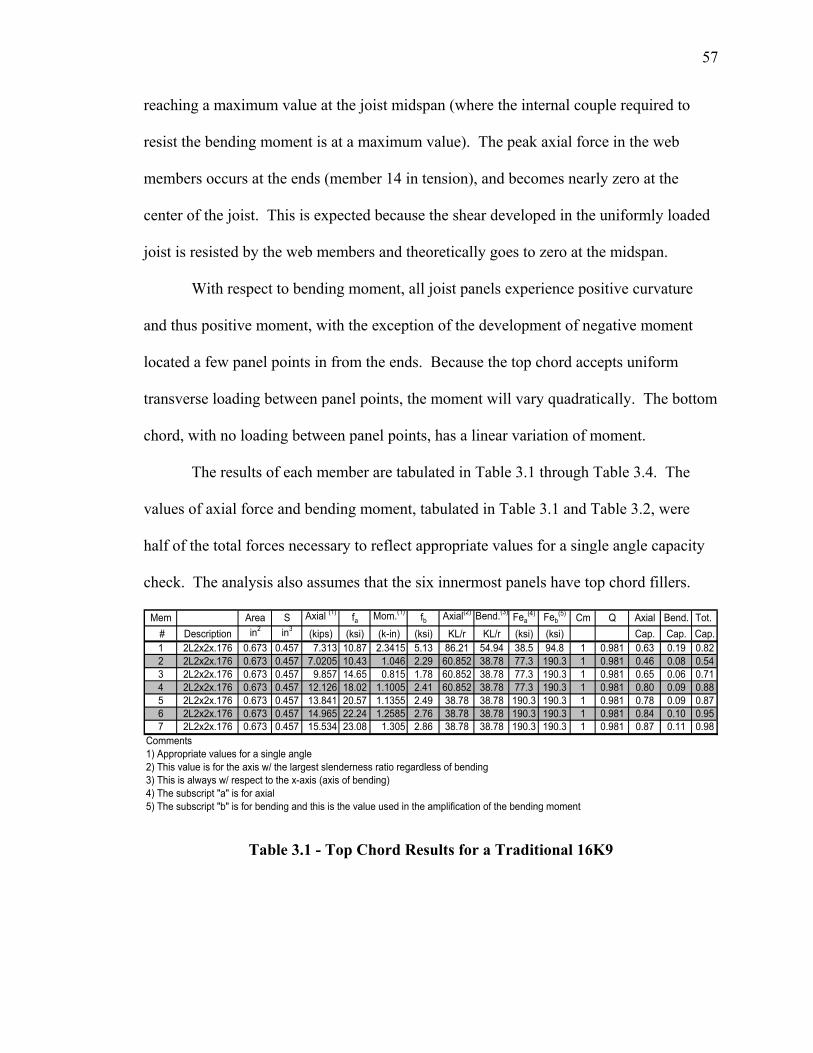
57
reaching a maximum value at the joist midspan (where the internal couple required to
resist the bending moment is at a maximum value). The peak axial force in the web
members occurs at the ends (member 14 in tension), and becomes nearly zero at the
center of the joist. This is expected because the shear developed in the uniformly loaded
joist is resisted by the web members and theoretically goes to zero at the midspan.
With respect to bending moment, all joist panels experience positive curvature
and thus positive moment, with the exception of the development of negative moment
located a few panel points in from the ends. Because the top chord accepts uniform
transverse loading between panel points, the moment will vary quadratically. The bottom
chord, with no loading between panel points, has a linear variation of moment.
The results of each member are tabulated in Table 3.1 through Table 3.4. The
values of axial force and bending moment, tabulated in Table 3.1 and Table 3.2, were
half of the total forces necessary to reflect appropriate values for a single angle capacity
check. The analysis also assumes that the six innermost panels have top chord fillers.
Mem Area S Axial (1) fa Mom.(1) fb Axial(2) Bend.(3) Fea(4) Feb
(5) Cm Q Axial Bend. Tot. # Description in2 in3 (kips) (ksi) (k-in) (ksi) KL/r KL/r (ksi) (ksi) Cap. Cap. Cap.1 2L2x2x.176 0.673 0.457 7.313 10.87 2.3415 5.13 86.21 54.94 38.5 94.8 1 0.981 0.63 0.19 0.822 2L2x2x.176 0.673 0.457 7.0205 10.43 1.046 2.29 60.852 38.78 77.3 190.3 1 0.981 0.46 0.08 0.543 2L2x2x.176 0.673 0.457 9.857 14.65 0.815 1.78 60.852 38.78 77.3 190.3 1 0.981 0.65 0.06 0.714 2L2x2x.176 0.673 0.457 12.126 18.02 1.1005 2.41 60.852 38.78 77.3 190.3 1 0.981 0.80 0.09 0.885 2L2x2x.176 0.673 0.457 13.841 20.57 1.1355 2.49 38.78 38.78 190.3 190.3 1 0.981 0.78 0.09 0.876 2L2x2x.176 0.673 0.457 14.965 22.24 1.2585 2.76 38.78 38.78 190.3 190.3 1 0.981 0.84 0.10 0.957 2L2x2x.176 0.673 0.457 15.534 23.08 1.305 2.86 38.78 38.78 190.3 190.3 1 0.981 0.87 0.11 0.98
Comments1) Appropriate values for a single angle2) This value is for the axis w/ the largest slenderness ratio regardless of bending3) This is always w/ respect to the x-axis (axis of bending)4) The subscript "a" is for axial5) The subscript "b" is for bending and this is the value used in the amplification of the bending moment
Table 3.1 - Top Chord Results for a Traditional 16K9
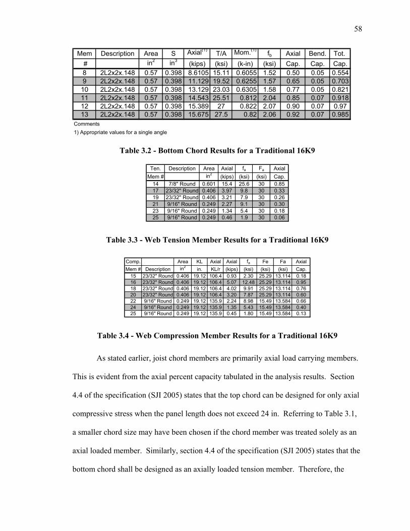
58
Mem Description Area S Axial(1)T/A Mom.(1) fb Axial Bend. Tot.
# in2 in3 (kips) (ksi) (k-in) (ksi) Cap. Cap. Cap.8 2L2x2x.148 0.57 0.398 8.6105 15.11 0.6055 1.52 0.50 0.05 0.5549 2L2x2x.148 0.57 0.398 11.129 19.52 0.6255 1.57 0.65 0.05 0.703
10 2L2x2x.148 0.57 0.398 13.129 23.03 0.6305 1.58 0.77 0.05 0.82111 2L2x2x.148 0.57 0.398 14.543 25.51 0.812 2.04 0.85 0.07 0.91812 2L2x2x.148 0.57 0.398 15.389 27 0.822 2.07 0.90 0.07 0.9713 2L2x2x.148 0.57 0.398 15.675 27.5 0.82 2.06 0.92 0.07 0.985
Comments1) Appropriate values for a single angle
Table 3.2 - Bottom Chord Results for a Traditional 16K9
Ten. Description Area Axial fa Fa AxialMem # in2 (kips) (ksi) (ksi) Cap.
14 7/8" Round 0.601 15.4 25.6 30 0.8517 23/32" Round 0.406 3.97 9.8 30 0.3319 23/32" Round 0.406 3.21 7.9 30 0.2621 9/16" Round 0.249 2.27 9.1 30 0.3023 9/16" Round 0.249 1.34 5.4 30 0.1825 9/16" Round 0.249 0.46 1.9 30 0.06
Table 3.3 - Web Tension Member Results for a Traditional 16K9
Comp. Area KL Axial Axial fa Fe Fa AxialMem # Description in2 in. KL/r (kips) (ksi) (ksi) (ksi) Cap.
15 23/32" Round 0.406 19.12 106.4 0.93 2.30 25.29 13.114 0.1816 23/32" Round 0.406 19.12 106.4 5.07 12.48 25.29 13.114 0.9518 23/32" Round 0.406 19.12 106.4 4.02 9.91 25.29 13.114 0.7620 23/32" Round 0.406 19.12 106.4 3.20 7.87 25.29 13.114 0.6022 9/16" Round 0.249 19.12 135.9 2.24 8.98 15.49 13.584 0.6624 9/16" Round 0.249 19.12 135.9 1.35 5.43 15.49 13.584 0.4025 9/16" Round 0.249 19.12 135.9 0.45 1.80 15.49 13.584 0.13
Table 3.4 - Web Compression Member Results for a Traditional 16K9
As stated earlier, joist chord members are primarily axial load carrying members.
This is evident from the axial percent capacity tabulated in the analysis results. Section
4.4 of the specification (SJI 2005) states that the top chord can be designed for only axial
compressive stress when the panel length does not exceed 24 in. Referring to Table 3.1,
a smaller chord size may have been chosen if the chord member was treated solely as an
axial loaded member. Similarly, section 4.4 of the specification (SJI 2005) states that the
bottom chord shall be designed as an axially loaded tension member. Therefore, the
59
bottom chord member size in Table 3.2 could also have been lowered, neglecting the
presence of bending moment.
Section 3.5.3 Proposed System Panel Design
Joist location is critical in the panel design because it mandates the load path of the
system. The load starts over a tributary width, located above a joist included in the group
of joists carrying the slab. These joists in turn “hang” on the joists running in the
perpendicular direction which do not directly carry the slab. Therefore, the loading will
inherently redistribute itself, attempting to mimic basic two-way plate behavior through
deformation compatibility. Unlike a plate however, the proposed system lacks the
material and, in turn, stiffness to carry a twisting moment (Mxy in the previous plate
example) across the floor bay.
Many preliminary designs were investigated, each considering a different manner
in which the joists could be arranged and spaced in a 30 ft. x 30 ft. interior bay. The
author designed a two-way joist arrangement that would use less than 10 joists (the
number of K-series joists needed in a traditional design), while utilizing chord sizes that
deviate little from the sizes used in the 16K9 joist design. This will establish a fair
comparison of how much steel is needed in each system to carry the prescribed loading.
It should be noted that the girders running perpendicular to the direction of the deck are
assumed to directly carry a portion of the deck, i.e. half the tributary width to the first
deck-supporting joist. Another critical assumption is that symmetrical adjacent floor
bays are present on all four sides of the “interior” design bay. Preliminary designs were
discarded on the basis of providing poor joist efficiency, fabrication problems, or
60
inefficient distribution of the loading to the supporting girders. Recall from Chapter 2
that the deeper joists are labeled dominant joists, while the shallower joists are considered
non-dominant joists.
The amount in which a joist can shift horizontally is restricted by the panel length
of the joists positioned in the orthogonal direction. This enables dominant joists to move
in 19 in. increments while non-dominant joists move in 24 in. increments. Another
restriction is the system’s inability to contain an odd number of non-dominant joists
(while keeping a symmetrical arrangement of these joists), which is prohibited by the
alignment of the panel points in the dominant joists.
Figure 3.14a shows the first configuration considered for the proposed design, in
which the joist spacing was divided evenly across each supporting girder. The biggest
problem with this design is its inefficiency. The load distribution will mimic that of a
two-way plate (i.e. the load is channeled towards the center of the bay in both directions).
Therefore, each joist would have to be designed individually, with the joists near the
edges being the smallest and increasing to a maximum size at the center of the panel.
Figure 3.14b places the joists near the center of the panel in an attempt to increase
joist efficiency without varying the joist’s chord sizes from one joist to the next. This
design is sufficient for the dominant joists because they don’t “directly” carry the deck.
The non-dominant joists, however, start developing unfavorable, and essentially
unreliable, loading because the slab over the middle joists experiences uplift.
The idea of using the configuration shown in Figure 3.14c was eliminated because
of limitations with the decking material. On a positive note, the design eliminated uplift,
and the joists are placed in the center of the slab where most of the load is channeled.
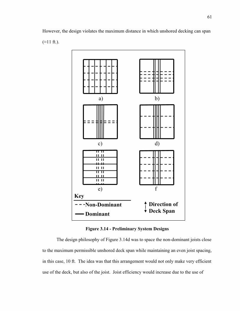
61
However, the design violates the maximum distance in which unshored decking can span
(≈11 ft.).
Figure 3.14 - Preliminary System Designs
The design philosophy of Figure 3.14d was to space the non-dominant joists close
to the maximum permissible unshored deck span while maintaining an even joist spacing,
in this case, 10 ft. The idea was that this arrangement would not only make very efficient
use of the deck, but also of the joist. Joist efficiency would increase due to the use of
Key Non-Dominant Dominant
Direction of Deck Span
a) b)
c) d)
e) f
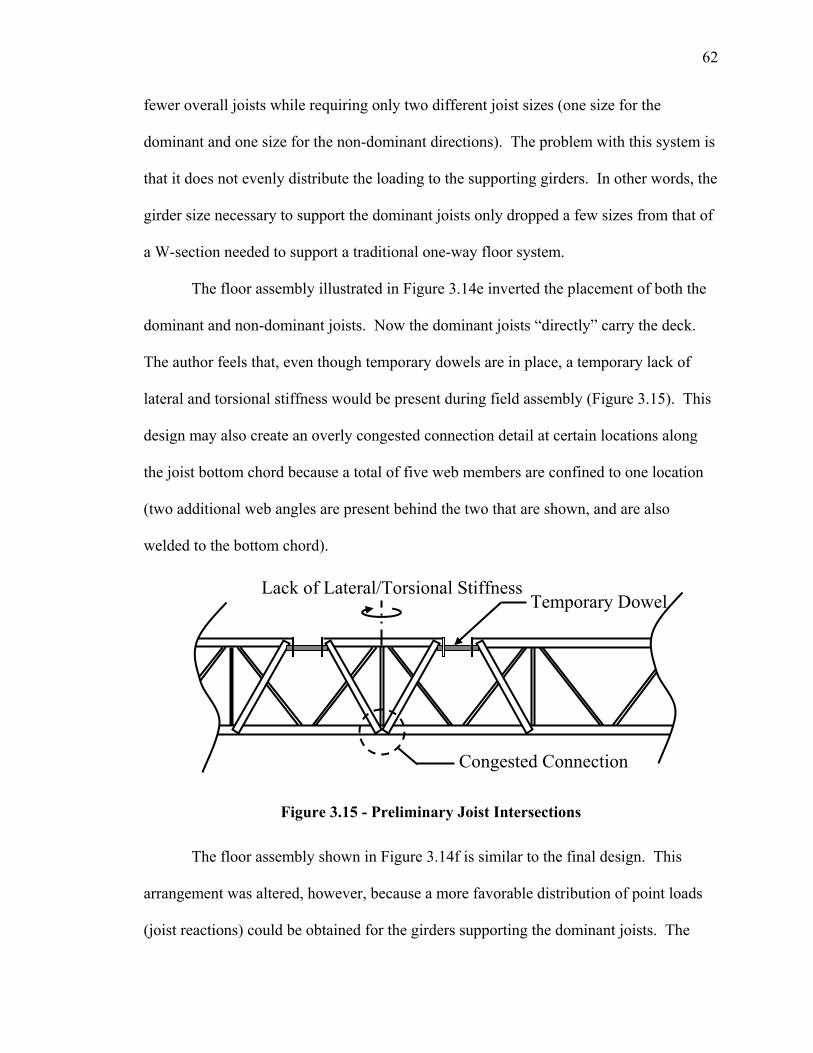
62
fewer overall joists while requiring only two different joist sizes (one size for the
dominant and one size for the non-dominant directions). The problem with this system is
that it does not evenly distribute the loading to the supporting girders. In other words, the
girder size necessary to support the dominant joists only dropped a few sizes from that of
a W-section needed to support a traditional one-way floor system.
The floor assembly illustrated in Figure 3.14e inverted the placement of both the
dominant and non-dominant joists. Now the dominant joists “directly” carry the deck.
The author feels that, even though temporary dowels are in place, a temporary lack of
lateral and torsional stiffness would be present during field assembly (Figure 3.15). This
design may also create an overly congested connection detail at certain locations along
the joist bottom chord because a total of five web members are confined to one location
(two additional web angles are present behind the two that are shown, and are also
welded to the bottom chord).
Figure 3.15 - Preliminary Joist Intersections
The floor assembly shown in Figure 3.14f is similar to the final design. This
arrangement was altered, however, because a more favorable distribution of point loads
(joist reactions) could be obtained for the girders supporting the dominant joists. The
Congested Connection
Lack of Lateral/Torsional Stiffness Temporary Dowel
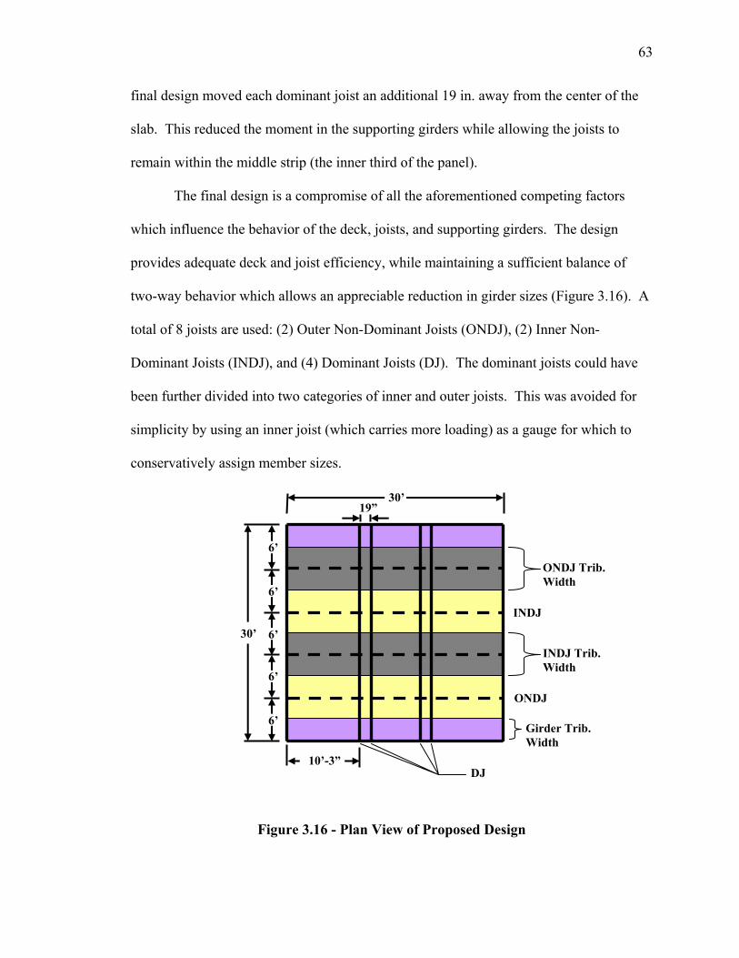
63
final design moved each dominant joist an additional 19 in. away from the center of the
slab. This reduced the moment in the supporting girders while allowing the joists to
remain within the middle strip (the inner third of the panel).
The final design is a compromise of all the aforementioned competing factors
which influence the behavior of the deck, joists, and supporting girders. The design
provides adequate deck and joist efficiency, while maintaining a sufficient balance of
two-way behavior which allows an appreciable reduction in girder sizes (Figure 3.16). A
total of 8 joists are used: (2) Outer Non-Dominant Joists (ONDJ), (2) Inner Non-
Dominant Joists (INDJ), and (4) Dominant Joists (DJ). The dominant joists could have
been further divided into two categories of inner and outer joists. This was avoided for
simplicity by using an inner joist (which carries more loading) as a gauge for which to
conservatively assign member sizes.
Figure 3.16 - Plan View of Proposed Design
ONDJ
INDJ
ONDJ Trib. Width
DJ
Girder Trib. Width
INDJ Trib. Width
6’
6’
6’
6’
6’
30’
30’
10’-3”
19”
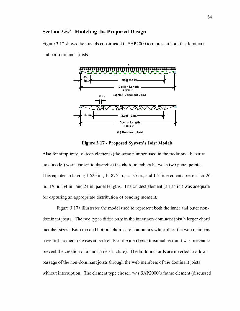
64
Section 3.5.4 Modeling the Proposed Design
Figure 3.17 shows the models constructed in SAP2000 to represent both the dominant
and non-dominant joists.
Figure 3.17 - Proposed System’s Joist Models
Also for simplicity, sixteen elements (the same number used in the traditional K-series
joist model) were chosen to discretize the chord members between two panel points.
This equates to having 1.625 in., 1.1875 in., 2.125 in., and 1.5 in. elements present for 26
in., 19 in., 34 in., and 24 in. panel lengths. The crudest element (2.125 in.) was adequate
for capturing an appropriate distribution of bending moment.
Figure 3.17a illustrates the model used to represent both the inner and outer non-
dominant joists. The two types differ only in the inner non-dominant joist’s larger chord
member sizes. Both top and bottom chords are continuous while all of the web members
have full moment releases at both ends of the members (torsional restraint was present to
prevent the creation of an unstable structure). The bottom chords are inverted to allow
passage of the non-dominant joists through the web members of the dominant joists
without interruption. The element type chosen was SAP2000’s frame element (discussed
(a) Non-Dominant Joist
Design Length = 356 in.
30 @ 9.5 in.35.5 in.
Design Length = 356 in.
22 @ 12 in.46 in.
6 in.
q
(b) Dominant Joist
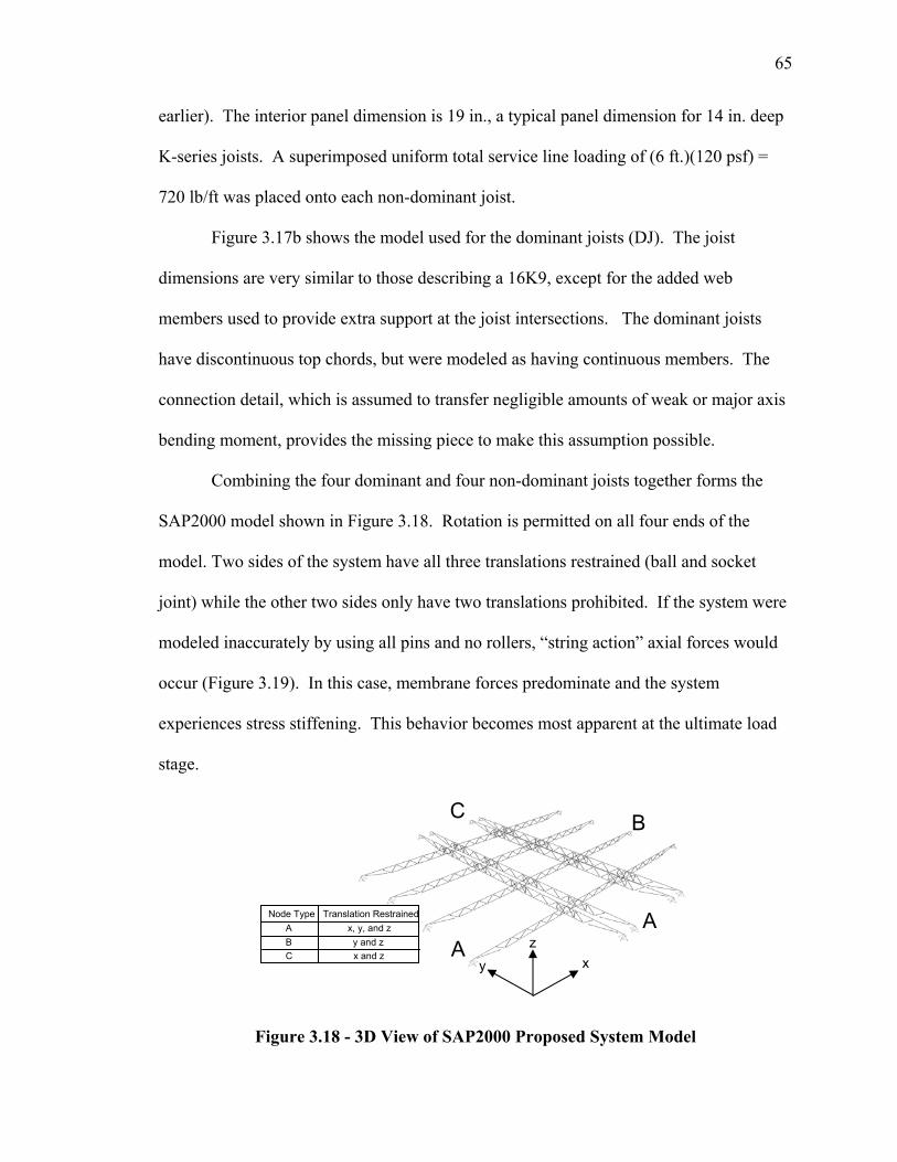
65
earlier). The interior panel dimension is 19 in., a typical panel dimension for 14 in. deep
K-series joists. A superimposed uniform total service line loading of (6 ft.)(120 psf) =
720 lb/ft was placed onto each non-dominant joist.
Figure 3.17b shows the model used for the dominant joists (DJ). The joist
dimensions are very similar to those describing a 16K9, except for the added web
members used to provide extra support at the joist intersections. The dominant joists
have discontinuous top chords, but were modeled as having continuous members. The
connection detail, which is assumed to transfer negligible amounts of weak or major axis
bending moment, provides the missing piece to make this assumption possible.
Combining the four dominant and four non-dominant joists together forms the
SAP2000 model shown in Figure 3.18. Rotation is permitted on all four ends of the
model. Two sides of the system have all three translations restrained (ball and socket
joint) while the other two sides only have two translations prohibited. If the system were
modeled inaccurately by using all pins and no rollers, “string action” axial forces would
occur (Figure 3.19). In this case, membrane forces predominate and the system
experiences stress stiffening. This behavior becomes most apparent at the ultimate load
stage.
Figure 3.18 - 3D View of SAP2000 Proposed System Model
AA
B C
x y z
A x, y, and z Node Type Translation Restrained
B y and z C x and z
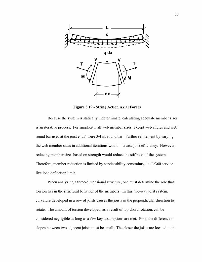
66
Figure 3.19 - String Action Axial Forces
Because the system is statically indeterminate, calculating adequate member sizes
is an iterative process. For simplicity, all web member sizes (except web angles and web
round bar used at the joist ends) were 3/4 in. round bar. Further refinement by varying
the web member sizes in additional iterations would increase joist efficiency. However,
reducing member sizes based on strength would reduce the stiffness of the system.
Therefore, member reduction is limited by serviceability constraints, i.e. L/360 service
live load deflection limit.
When analyzing a three-dimensional structure, one must determine the role that
torsion has in the structural behavior of the members. In this two-way joist system,
curvature developed in a row of joists causes the joists in the perpendicular direction to
rotate. The amount of torsion developed, as a result of top chord rotation, can be
considered negligible as long as a few key assumptions are met. First, the difference in
slopes between two adjacent joists must be small. The closer the joists are located to the
q dx
T T
M
V V
M
L q
dx
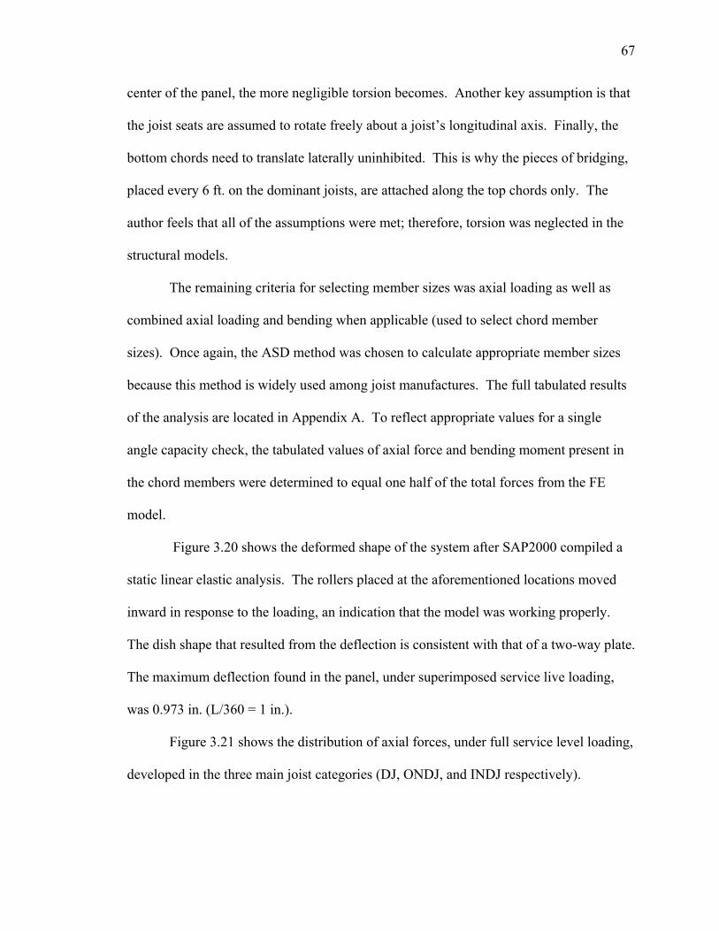
67
center of the panel, the more negligible torsion becomes. Another key assumption is that
the joist seats are assumed to rotate freely about a joist’s longitudinal axis. Finally, the
bottom chords need to translate laterally uninhibited. This is why the pieces of bridging,
placed every 6 ft. on the dominant joists, are attached along the top chords only. The
author feels that all of the assumptions were met; therefore, torsion was neglected in the
structural models.
The remaining criteria for selecting member sizes was axial loading as well as
combined axial loading and bending when applicable (used to select chord member
sizes). Once again, the ASD method was chosen to calculate appropriate member sizes
because this method is widely used among joist manufactures. The full tabulated results
of the analysis are located in Appendix A. To reflect appropriate values for a single
angle capacity check, the tabulated values of axial force and bending moment present in
the chord members were determined to equal one half of the total forces from the FE
model.
Figure 3.20 shows the deformed shape of the system after SAP2000 compiled a
static linear elastic analysis. The rollers placed at the aforementioned locations moved
inward in response to the loading, an indication that the model was working properly.
The dish shape that resulted from the deflection is consistent with that of a two-way plate.
The maximum deflection found in the panel, under superimposed service live loading,
was 0.973 in. (L/360 = 1 in.).
Figure 3.21 shows the distribution of axial forces, under full service level loading,
developed in the three main joist categories (DJ, ONDJ, and INDJ respectively).
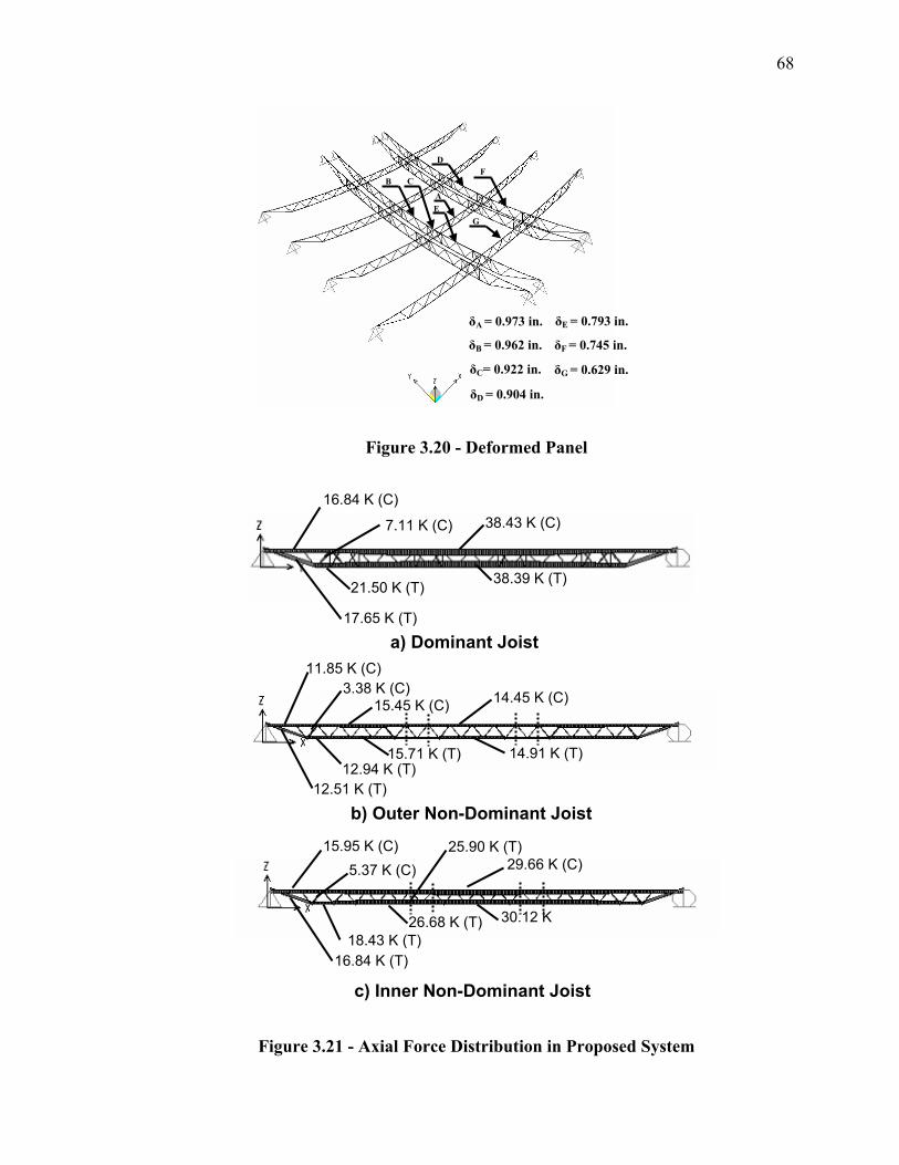
68
Figure 3.20 - Deformed Panel
Figure 3.21 - Axial Force Distribution in Proposed System
16.84 K (C)
7.11 K (C)
17.65 K (T)
38.43 K (C)
38.39 K (T)
11.85 K (C)
15.45 K (C) 14.45 K (C)
14.91 K (T) 15.71 K (T)
12.51 K (T)
3.38 K (C)
15.95 K (C) 29.66 K (C)
30.12 K
16.84 K (T)
5.37 K (C)
a) Dominant Joist
b) Outer Non-Dominant Joist
18.43 K (T)
12.94 K (T)
21.50 K (T)
25.90 K (T)
26.68 K (T)
A
C
E
F B
G
δA = 0.973 in.
δB = 0.962 in.
δD = 0.904 in.
δC= 0.922 in. δG = 0.629 in.
δE = 0.793 in.
δF = 0.745 in.
D
c) Inner Non-Dominant Joist
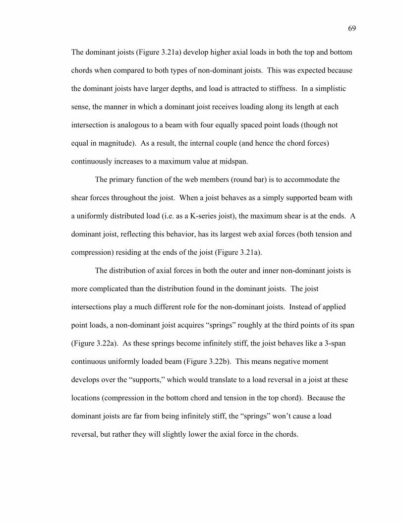
69
The dominant joists (Figure 3.21a) develop higher axial loads in both the top and bottom
chords when compared to both types of non-dominant joists. This was expected because
the dominant joists have larger depths, and load is attracted to stiffness. In a simplistic
sense, the manner in which a dominant joist receives loading along its length at each
intersection is analogous to a beam with four equally spaced point loads (though not
equal in magnitude). As a result, the internal couple (and hence the chord forces)
continuously increases to a maximum value at midspan.
The primary function of the web members (round bar) is to accommodate the
shear forces throughout the joist. When a joist behaves as a simply supported beam with
a uniformly distributed load (i.e. as a K-series joist), the maximum shear is at the ends. A
dominant joist, reflecting this behavior, has its largest web axial forces (both tension and
compression) residing at the ends of the joist (Figure 3.21a).
The distribution of axial forces in both the outer and inner non-dominant joists is
more complicated than the distribution found in the dominant joists. The joist
intersections play a much different role for the non-dominant joists. Instead of applied
point loads, a non-dominant joist acquires “springs” roughly at the third points of its span
(Figure 3.22a). As these springs become infinitely stiff, the joist behaves like a 3-span
continuous uniformly loaded beam (Figure 3.22b). This means negative moment
develops over the “supports,” which would translate to a load reversal in a joist at these
locations (compression in the bottom chord and tension in the top chord). Because the
dominant joists are far from being infinitely stiff, the “springs” won’t cause a load
reversal, but rather they will slightly lower the axial force in the chords.

70
Figure 3.22 - Spring Analogy for Non-Dominant Joists
This “spring” effect is most pronounced in the outer non-dominant joists. Axial
forces in both the top and bottom chords are reduced at the joist intersections (shown as
dashed lines in Figure 3.21b). In fact, the axial forces run out of room to recover
(moving left to right) and the maximum chord forces no longer occur at joist midspan.
Because the inner non-dominant joists are closer to the center of the panel, the “spring”
stiffness provided by the dominant joists will be lower. This is why the axial forces,
though still reduced by a small amount at the joist intersections, recover afterwards and
are hightest at the joist midspan (Figure 3.21).
Figure 3.23 shows the major-axis moment distributions, under full service level
loading, developed in the three main joist categories. It should be noted that because all
the loading received from the panel is in the vertical direction only, minor-axis bending
(though included in the model) was considered negligible. The dominant joist does not
have uniform loading between panel points. Therefore, the highest order moment present
in either the top or bottom chord is linear (Figure 3.23a).
b)
K1 K2 K1 & K2 inf.
a)
K1 K2
Compression
Tension
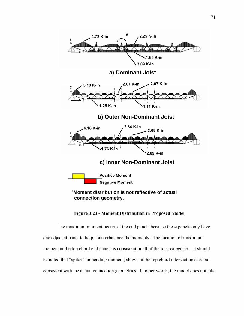
71
Figure 3.23 - Moment Distribution in Proposed Model
The maximum moment occurs at the end panels because these panels only have
one adjacent panel to help counterbalance the moments. The location of maximum
moment at the top chord end panels is consistent in all of the joist categories. It should
be noted that “spikes” in bending moment, shown at the top chord intersections, are not
consistent with the actual connection geometries. In other words, the model does not take
4.72 K-in 2.25 K-in
1.65 K-in 3.09 K-in
5.13 K-in 2.07 K-in
1.11 K-in 1.25 K-in
6.18 K-in
1.76 K-in
3.09 K-in
2.09 K-in
*
*Moment distribution is not reflective of actual connection geometry.
a) Dominant Joist
b) Outer Non-Dominant Joist
c) Inner Non-Dominant Joist
Positive Moment Negative Moment
2.07 K-in
2.34 K-in
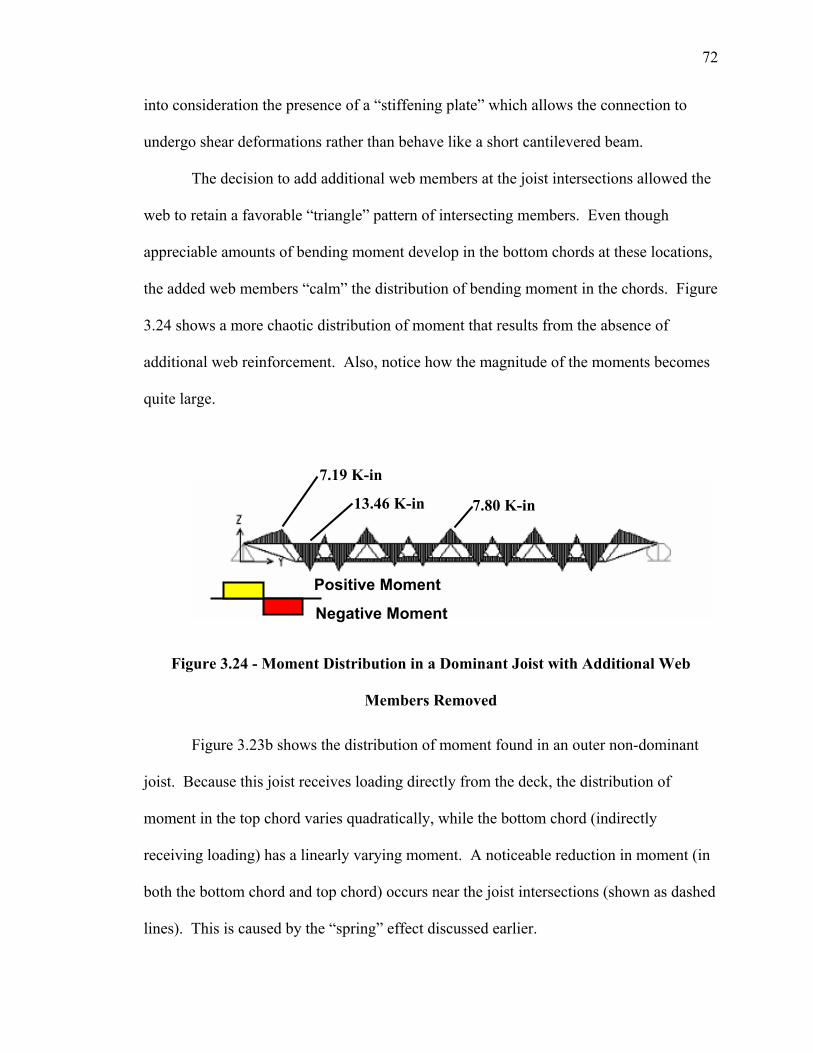
72
into consideration the presence of a “stiffening plate” which allows the connection to
undergo shear deformations rather than behave like a short cantilevered beam.
The decision to add additional web members at the joist intersections allowed the
web to retain a favorable “triangle” pattern of intersecting members. Even though
appreciable amounts of bending moment develop in the bottom chords at these locations,
the added web members “calm” the distribution of bending moment in the chords. Figure
3.24 shows a more chaotic distribution of moment that results from the absence of
additional web reinforcement. Also, notice how the magnitude of the moments becomes
quite large.
Figure 3.24 - Moment Distribution in a Dominant Joist with Additional Web
Members Removed
Figure 3.23b shows the distribution of moment found in an outer non-dominant
joist. Because this joist receives loading directly from the deck, the distribution of
moment in the top chord varies quadratically, while the bottom chord (indirectly
receiving loading) has a linearly varying moment. A noticeable reduction in moment (in
both the bottom chord and top chord) occurs near the joist intersections (shown as dashed
lines). This is caused by the “spring” effect discussed earlier.
7.19 K-in
13.46 K-in 7.80 K-in
Positive Moment
Negative Moment
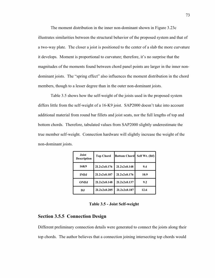
73
The moment distribution in the inner non-dominant shown in Figure 3.23c
illustrates similarities between the structural behavior of the proposed system and that of
a two-way plate. The closer a joist is positioned to the center of a slab the more curvature
it develops. Moment is proportional to curvature; therefore, it’s no surprise that the
magnitudes of the moments found between chord panel points are larger in the inner non-
dominant joists. The “spring effect” also influences the moment distribution in the chord
members, though to a lesser degree than in the outer non-dominant joists.
Table 3.5 shows how the self-weight of the joists used in the proposed system
differs little from the self-weight of a 16-K9 joist. SAP2000 doesn’t take into account
additional material from round bar fillets and joist seats, nor the full lengths of top and
bottom chords. Therefore, tabulated values from SAP2000 slightly underestimate the
true member self-weight. Connection hardware will slightly increase the weight of the
non-dominant joists.
Table 3.5 - Joist Self-weight
Section 3.5.5 Connection Design
Different preliminary connection details were generated to connect the joists along their
top chords. The author believes that a connection joining intersecting top chords would
Top Chord Bottom Chord Self Wt. (lbf)
2L2x2x0.176 2L2x2x0.148 9.4 16K9
Joist Description
INDJ
ONDJ
DJ
2L2x2x0.187 2L2x2x0.176 10.9
2L2x2x0.148 2L2x2x0.137 9.2
2L2x2x0.205 2L2x2x0.187 12.6
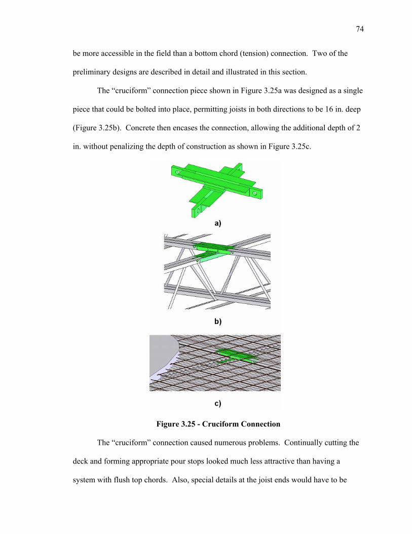
74
be more accessible in the field than a bottom chord (tension) connection. Two of the
preliminary designs are described in detail and illustrated in this section.
The “cruciform” connection piece shown in Figure 3.25a was designed as a single
piece that could be bolted into place, permitting joists in both directions to be 16 in. deep
(Figure 3.25b). Concrete then encases the connection, allowing the additional depth of 2
in. without penalizing the depth of construction as shown in Figure 3.25c.
Figure 3.25 - Cruciform Connection
The “cruciform” connection caused numerous problems. Continually cutting the
deck and forming appropriate pour stops looked much less attractive than having a
system with flush top chords. Also, special details at the joist ends would have to be
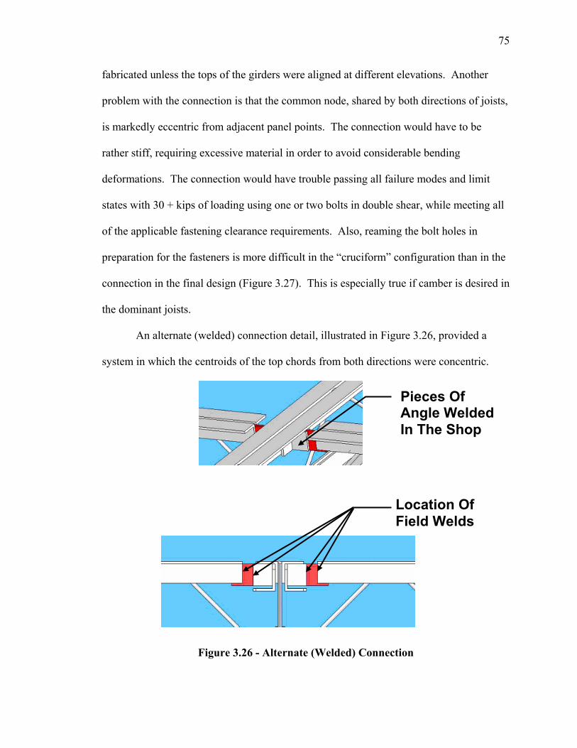
75
fabricated unless the tops of the girders were aligned at different elevations. Another
problem with the connection is that the common node, shared by both directions of joists,
is markedly eccentric from adjacent panel points. The connection would have to be
rather stiff, requiring excessive material in order to avoid considerable bending
deformations. The connection would have trouble passing all failure modes and limit
states with 30 + kips of loading using one or two bolts in double shear, while meeting all
of the applicable fastening clearance requirements. Also, reaming the bolt holes in
preparation for the fasteners is more difficult in the “cruciform” configuration than in the
connection in the final design (Figure 3.27). This is especially true if camber is desired in
the dominant joists.
An alternate (welded) connection detail, illustrated in Figure 3.26, provided a
system in which the centroids of the top chords from both directions were concentric.
Figure 3.26 - Alternate (Welded) Connection
Location Of Field Welds
Pieces Of Angle Welded In The Shop
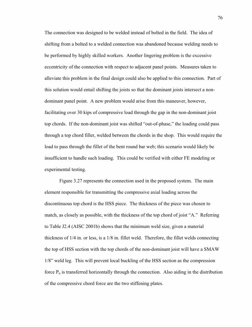
76
The connection was designed to be welded instead of bolted in the field. The idea of
shifting from a bolted to a welded connection was abandoned because welding needs to
be performed by highly skilled workers. Another lingering problem is the excessive
eccentricity of the connection with respect to adjacent panel points. Measures taken to
alleviate this problem in the final design could also be applied to this connection. Part of
this solution would entail shifting the joists so that the dominant joists intersect a non-
dominant panel point. A new problem would arise from this maneuver, however,
facilitating over 30 kips of compressive load through the gap in the non-dominant joist
top chords. If the non-dominant joist was shifted “out-of-phase,” the loading could pass
through a top chord filler, welded between the chords in the shop. This would require the
load to pass through the fillet of the bent round bar web; this scenario would likely be
insufficient to handle such loading. This could be verified with either FE modeling or
experimental testing.
Figure 3.27 represents the connection used in the proposed system. The main
element responsible for transmitting the compressive axial loading across the
discontinuous top chord is the HSS piece. The thickness of the piece was chosen to
match, as closely as possible, with the thickness of the top chord of joist “A.” Referring
to Table J2.4 (AISC 2001b) shows that the minimum weld size, given a material
thickness of 1/4 in. or less, is a 1/8 in. fillet weld. Therefore, the fillet welds connecting
the top of HSS section with the top chords of the non-dominant joist will have a SMAW
1/8” weld leg. This will prevent local buckling of the HSS section as the compression
force Pu is transferred horizontally through the connection. Also aiding in the distribution
of the compressive chord force are the two stiffening plates.
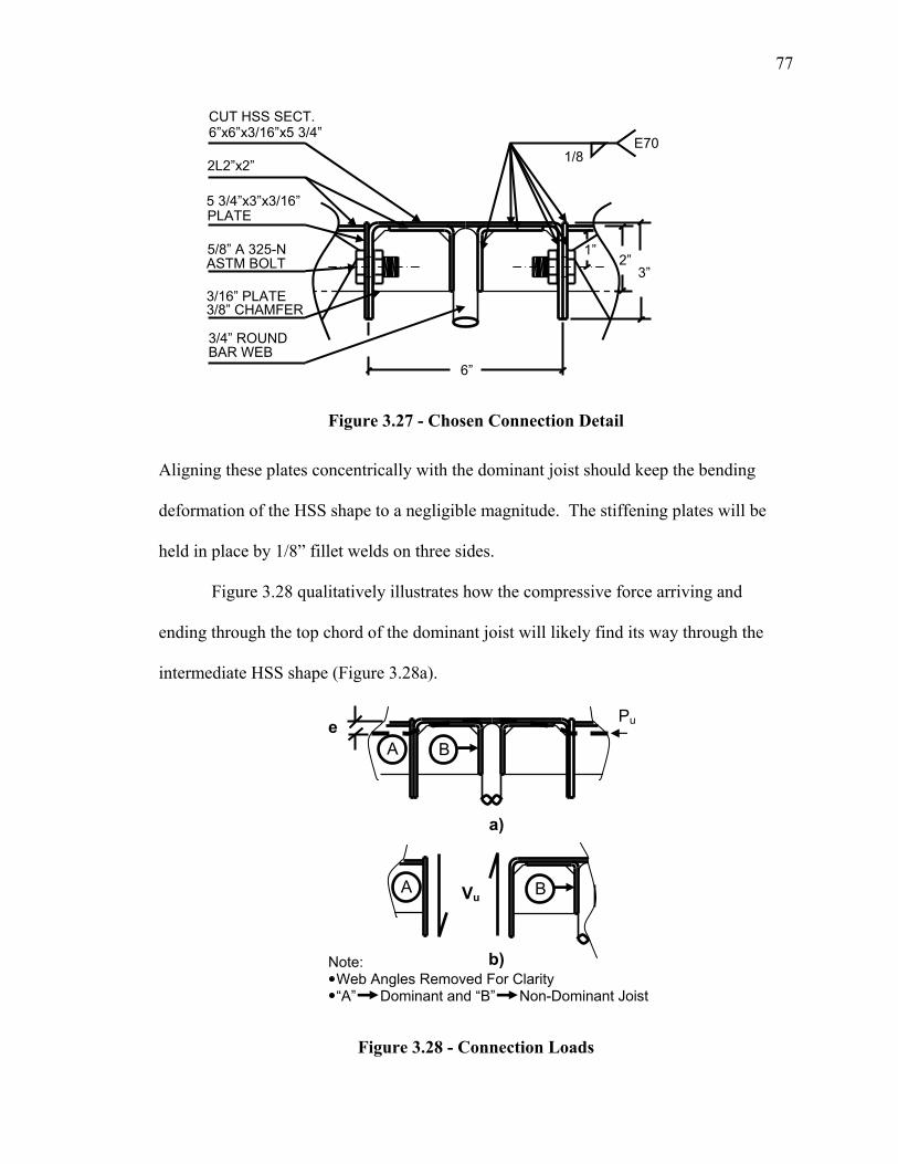
77
Figure 3.27 - Chosen Connection Detail
Aligning these plates concentrically with the dominant joist should keep the bending
deformation of the HSS shape to a negligible magnitude. The stiffening plates will be
held in place by 1/8” fillet welds on three sides.
Figure 3.28 qualitatively illustrates how the compressive force arriving and
ending through the top chord of the dominant joist will likely find its way through the
intermediate HSS shape (Figure 3.28a).
Figure 3.28 - Connection Loads
BA
Pu
Vu B A
e
a)
b) Note: Web Angles Removed For Clarity “A” Dominant and “B” Non-Dominant Joist
6”
2”
CUT HSS SECT. 6”x6”x3/16”x5 3/4”
2L2”x2”
PLATE
5/8” A 325-N ASTM BOLT
3/16” PLATE 3/8” CHAMFER
3/4” ROUND BAR WEB
3” 1”
E70 1/8
5 3/4”x3”x3/16”
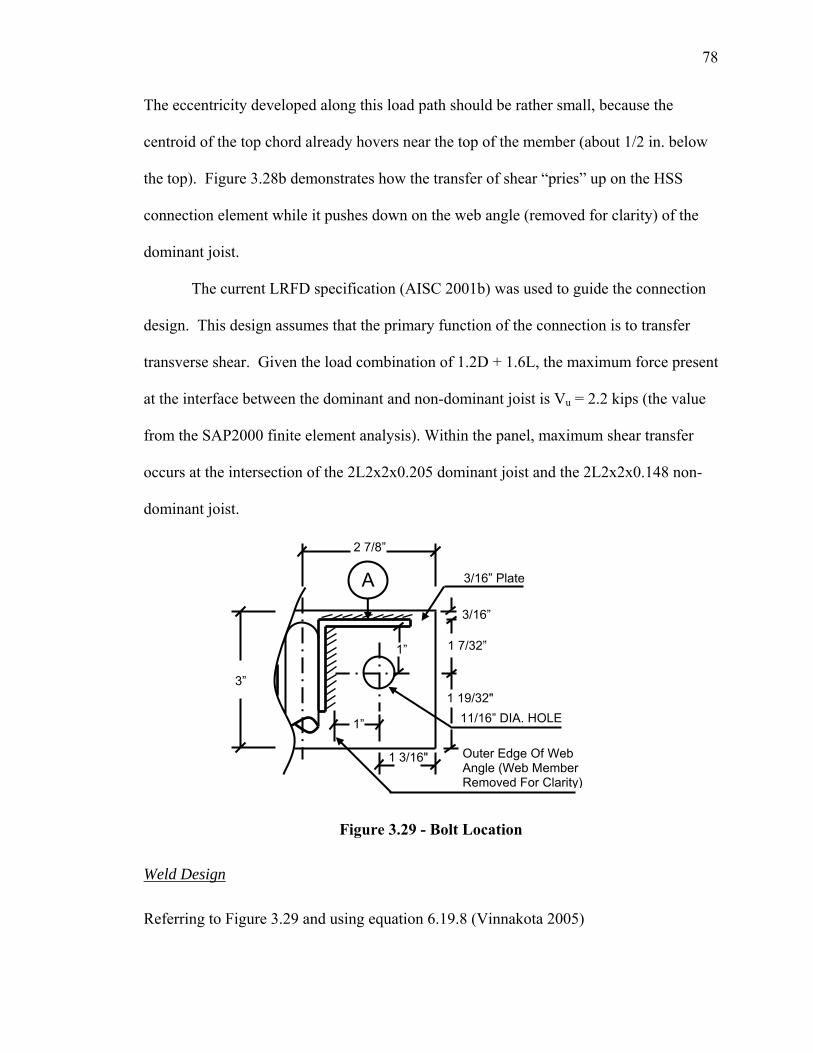
78
The eccentricity developed along this load path should be rather small, because the
centroid of the top chord already hovers near the top of the member (about 1/2 in. below
the top). Figure 3.28b demonstrates how the transfer of shear “pries” up on the HSS
connection element while it pushes down on the web angle (removed for clarity) of the
dominant joist.
The current LRFD specification (AISC 2001b) was used to guide the connection
design. This design assumes that the primary function of the connection is to transfer
transverse shear. Given the load combination of 1.2D + 1.6L, the maximum force present
at the interface between the dominant and non-dominant joist is Vu = 2.2 kips (the value
from the SAP2000 finite element analysis). Within the panel, maximum shear transfer
occurs at the intersection of the 2L2x2x0.205 dominant joist and the 2L2x2x0.148 non-
dominant joist.
Figure 3.29 - Bolt Location
Weld Design
Referring to Figure 3.29 and using equation 6.19.8 (Vinnakota 2005)
1 7/32”
1 19/32"
1”
1” 11/16” DIA. HOLE
A 3/16” Plate
2 7/8”
Outer Edge Of Web Angle (Web Member Removed For Clarity)
1 3/16"
3/16”
3”
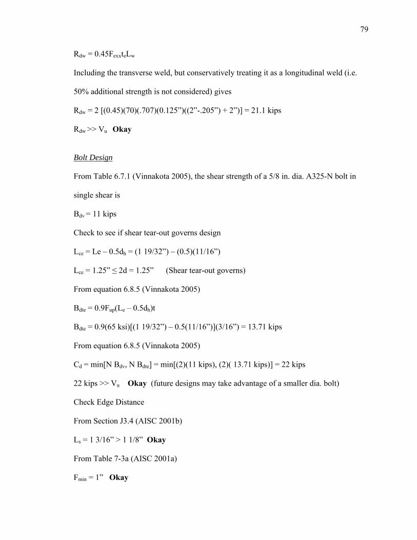
79
Rdw = 0.45FexxteLw
Including the transverse weld, but conservatively treating it as a longitudinal weld (i.e.
50% additional strength is not considered) gives
Rdw = 2 [(0.45)(70)(.707)(0.125”)((2”-.205”) + 2”)] = 21.1 kips
Rdw >> Vu Okay
Bolt Design
From Table 6.7.1 (Vinnakota 2005), the shear strength of a 5/8 in. dia. A325-N bolt in
single shear is
Bdv = 11 kips
Check to see if shear tear-out governs design
Lce = Le – 0.5dh = (1 19/32”) – (0.5)(11/16”)
Lce = 1.25” ≤ 2d = 1.25” (Shear tear-out governs)
From equation 6.8.5 (Vinnakota 2005)
Bdte = 0.9Fup(Le – 0.5dh)t
Bdte = 0.9(65 ksi)[(1 19/32”) – 0.5(11/16”)](3/16”) = 13.71 kips
From equation 6.8.5 (Vinnakota 2005)
Cd = min[N Bdv, N Bdte] = min[(2)(11 kips), (2)( 13.71 kips)] = 22 kips
22 kips >> Vu Okay (future designs may take advantage of a smaller dia. bolt)
Check Edge Distance
From Section J3.4 (AISC 2001b)
Ls = 1 3/16” > 1 1/8” Okay
From Table 7-3a (AISC 2001a)
Fmin = 1” Okay
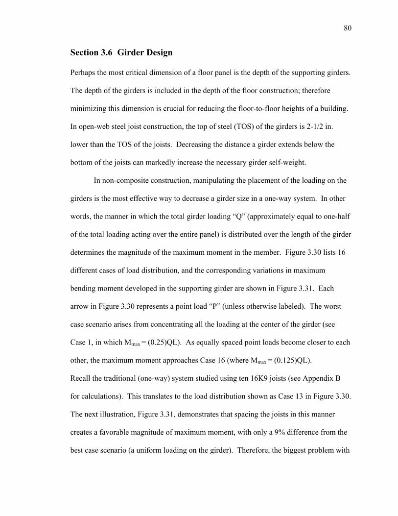
80
Section 3.6 Girder Design
Perhaps the most critical dimension of a floor panel is the depth of the supporting girders.
The depth of the girders is included in the depth of the floor construction; therefore
minimizing this dimension is crucial for reducing the floor-to-floor heights of a building.
In open-web steel joist construction, the top of steel (TOS) of the girders is 2-1/2 in.
lower than the TOS of the joists. Decreasing the distance a girder extends below the
bottom of the joists can markedly increase the necessary girder self-weight.
In non-composite construction, manipulating the placement of the loading on the
girders is the most effective way to decrease a girder size in a one-way system. In other
words, the manner in which the total girder loading “Q” (approximately equal to one-half
of the total loading acting over the entire panel) is distributed over the length of the girder
determines the magnitude of the maximum moment in the member. Figure 3.30 lists 16
different cases of load distribution, and the corresponding variations in maximum
bending moment developed in the supporting girder are shown in Figure 3.31. Each
arrow in Figure 3.30 represents a point load “P” (unless otherwise labeled). The worst
case scenario arises from concentrating all the loading at the center of the girder (see
Case 1, in which Mmax = (0.25)QL). As equally spaced point loads become closer to each
other, the maximum moment approaches Case 16 (where Mmax = (0.125)QL).
Recall the traditional (one-way) system studied using ten 16K9 joists (see Appendix B
for calculations). This translates to the load distribution shown as Case 13 in Figure 3.30.
The next illustration, Figure 3.31, demonstrates that spacing the joists in this manner
creates a favorable magnitude of maximum moment, with only a 9% difference from the
best case scenario (a uniform loading on the girder). Therefore, the biggest problem with
81
this joist configuration doesn’t reside with the way the joist reactions are dispersed along
the girder, but rather in the way in which the load arrives there in the first place, i.e. one-
way action.
Figure 3.30 - Load Cases
0
0.05
0.1
0.15
0.2
0.25
0.3
0 1 2 3 4 5 6 7 8 9 10 11 12 13 14 15 16 17
Case #
QL
coef
ficie
nt
Figure 3.31 - Variation in Maximum Moment
Case 1
Case 2
Case 3
Case 4
Case 5
Case 6
Case 7
Case 8
Case 9
Case 10
Case 11
Case 12
Case 13
Case 14
Case 15
Case 16
¾ P ¾ P P P
P
q
L
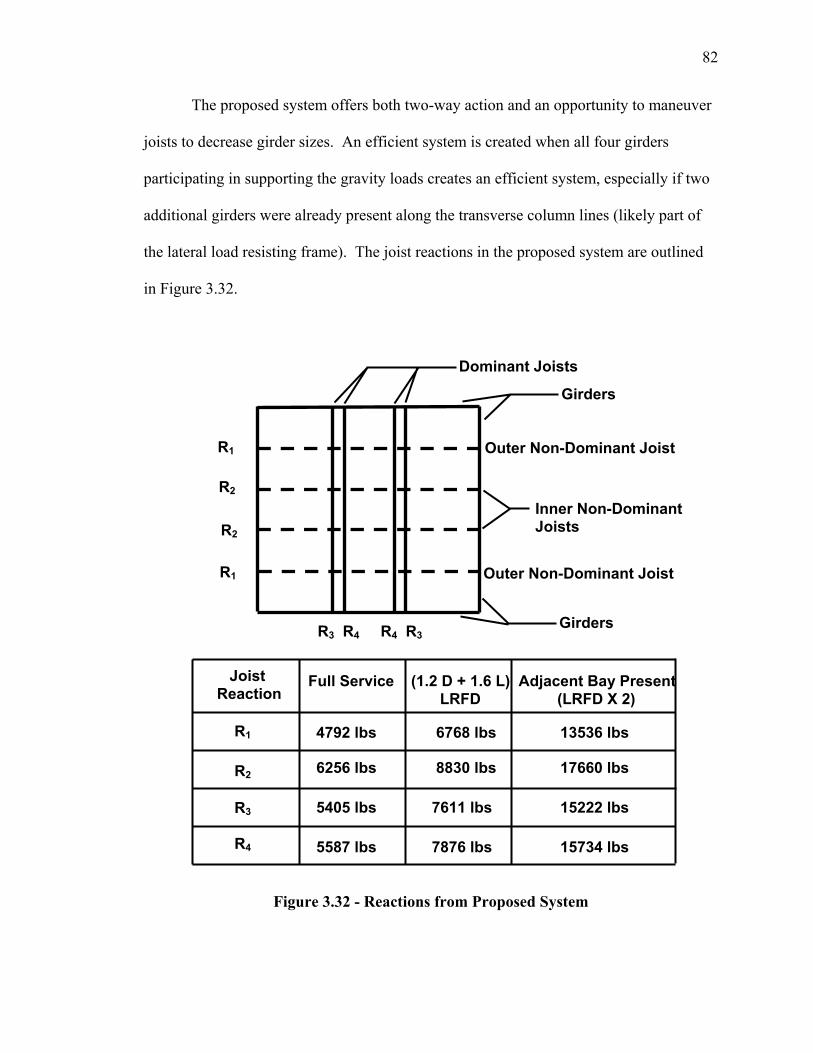
82
The proposed system offers both two-way action and an opportunity to maneuver
joists to decrease girder sizes. An efficient system is created when all four girders
participating in supporting the gravity loads creates an efficient system, especially if two
additional girders were already present along the transverse column lines (likely part of
the lateral load resisting frame). The joist reactions in the proposed system are outlined
in Figure 3.32.
Figure 3.32 - Reactions from Proposed System
Outer Non-Dominant Joist
Inner Non-Dominant Joists
Outer Non-Dominant Joist
Dominant Joists
Girders R3 R4 R4 R3
R1
R2
R2
R1
Girders
Full Service (1.2 D + 1.6 L) Adjacent Bay Present LRFD (LRFD X 2)
4792 lbs 6768 lbs 13536 lbs 6256 lbs 8830 lbs 17660 lbs
5405 lbs 7611 lbs 15222 lbs
5587 lbs 7876 lbs 15734 lbs
R1
Joist Reaction
R2 R3 R4
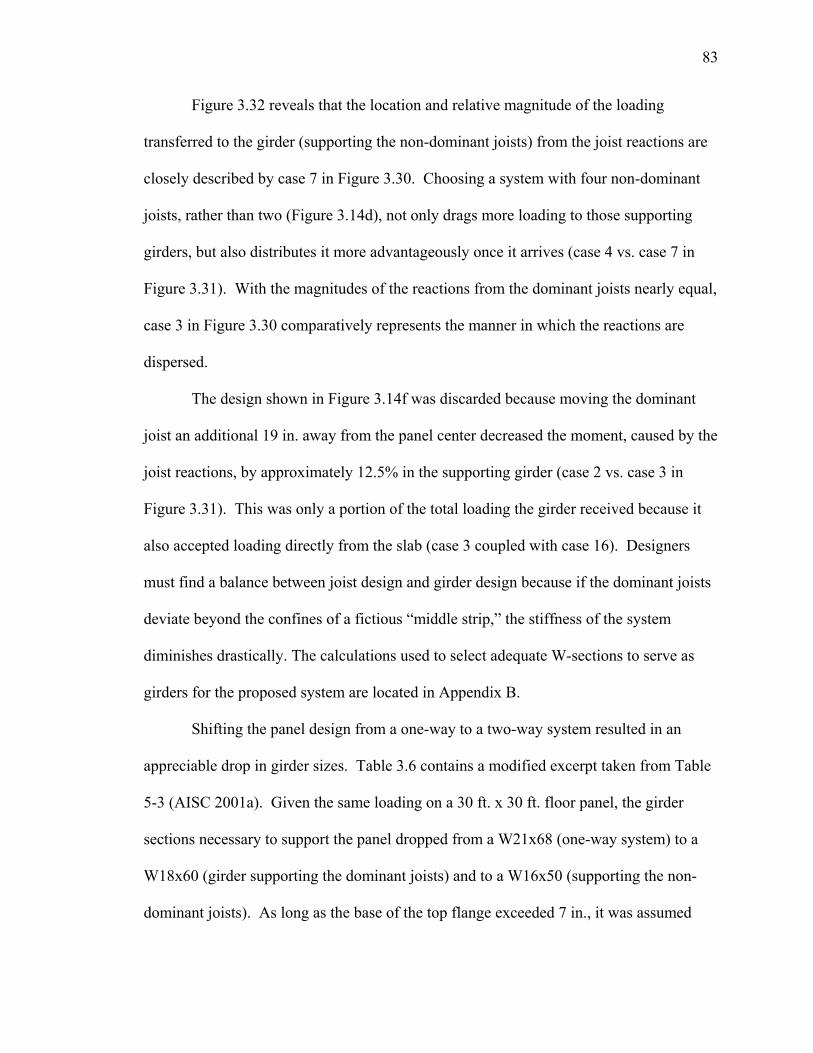
83
Figure 3.32 reveals that the location and relative magnitude of the loading
transferred to the girder (supporting the non-dominant joists) from the joist reactions are
closely described by case 7 in Figure 3.30. Choosing a system with four non-dominant
joists, rather than two (Figure 3.14d), not only drags more loading to those supporting
girders, but also distributes it more advantageously once it arrives (case 4 vs. case 7 in
Figure 3.31). With the magnitudes of the reactions from the dominant joists nearly equal,
case 3 in Figure 3.30 comparatively represents the manner in which the reactions are
dispersed.
The design shown in Figure 3.14f was discarded because moving the dominant
joist an additional 19 in. away from the panel center decreased the moment, caused by the
joist reactions, by approximately 12.5% in the supporting girder (case 2 vs. case 3 in
Figure 3.31). This was only a portion of the total loading the girder received because it
also accepted loading directly from the slab (case 3 coupled with case 16). Designers
must find a balance between joist design and girder design because if the dominant joists
deviate beyond the confines of a fictious “middle strip,” the stiffness of the system
diminishes drastically. The calculations used to select adequate W-sections to serve as
girders for the proposed system are located in Appendix B.
Shifting the panel design from a one-way to a two-way system resulted in an
appreciable drop in girder sizes. Table 3.6 contains a modified excerpt taken from Table
5-3 (AISC 2001a). Given the same loading on a 30 ft. x 30 ft. floor panel, the girder
sections necessary to support the panel dropped from a W21x68 (one-way system) to a
W18x60 (girder supporting the dominant joists) and to a W16x50 (supporting the non-
dominant joists). As long as the base of the top flange exceeded 7 in., it was assumed
84
that two joist seats (typically 4 inches long) could be accommodated with only slight
modification to the end detail. Selected girders passed all strength and live load
deflection requirements.
Table 3.6 - Girder Selection
Shape Zx (in3) Ix (in
4) bf (in)W24x68 177 1830 8.97W16x89 176 1310 10.4
W14x99†† 173 1110 14.6W21x73 172 1600 8.3W12x106 164 933 12.2W18x76 163 1330 11
W21x68 160 1480 8.27W14x90†† 157 999 14.5
W24x62 154 1560 7.04W16x77 151 1120 10.3W12x96 147 833 12.2W10x112 147 716 10.4W18x71 146 1170 7.64
W21x62 144 1330 8.24W14x82 139 882 10.1
W24x55 135 1360 7.01W18x65 133 1070 7.59W12x87 132 740 12.1W16x67 131 963 10.2W10x100 130 623 10.3W21x57 129 1170 6.56
W21x55 126 1140 8.22W14x74 126 796 10.1W18x60 123 984 7.56W12x79 119 662 12.1W14x68 115 722 10W10x88 113 534 10.3
W18x55 112 890 7.53
W21x50 111 989 6.53W12x72 108 597 12
W21x48†† 107 959 8.14W16x57 105 758 7.12W14x61 102 640 9.99W18x50 101 800 7.5W10x77 97.6 455 10.2
W12x65†† 96.8 533 12
W21x44 95.8 847 6.5W16x50 92 659 7.07W18x46 90.7 712 6.06W14x53 87.1 541 8.06W12x58 86.4 475 10W10x68 85.3 394 10.1W16x45 82.3 586 7.04
W18x40 78.4 612 6.02W14x48 78.4 485 8.03W12x53 77.9 425 9.99W10x60 74.6 341 10.1
One-Way System
Two-Way System (Supporting DJ)
Two-Way System (Supporting NDJ)
85
Chapter 4 Composite Design
Section 4.1 Introduction
Taking advantage of composite action, when designing one-way open-web steel joist
floor systems, has become increasingly popular in recent decades. Composite
construction is attractive because it allows shallower floor depths, consequently reducing
the costs of fireproofing, foundations, etc. A designer has the option of making either the
open-web joists or the supporting girders composite (or both composite). Joist members
are designed to be “fully composite” but it is usually more economical, in the case of
using wide-flange steel sections, to design the girders as “partially composite” members.
The proposed two-way steel floor system was designed as a non-composite
system but can also offer composite capabilities to the designer. This chapter discusses
three different ways in which the joists and steel decking can be combined to achieve
composite action. Also included is a discussion on how the load distribution of the
system could be impacted by developing steel decking to force the slab to predominantly
span in two directions. This is followed by a suggestion explaining how one can
construct an FE model to predict the composite behavior of the proposed system. Finally,
composite girder options are investigated and the results of a composite design are
summarized to illustrate how the member sizes differ from those of non-composite
construction.
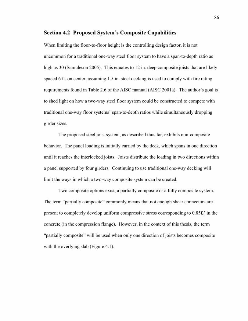
86
Section 4.2 Proposed System’s Composite Capabilities
When limiting the floor-to-floor height is the controlling design factor, it is not
uncommon for a traditional one-way steel floor system to have a span-to-depth ratio as
high as 30 (Samuleson 2005). This equates to 12 in. deep composite joists that are likely
spaced 6 ft. on center, assuming 1.5 in. steel decking is used to comply with fire rating
requirements found in Table 2.6 of the AISC manual (AISC 2001a). The author’s goal is
to shed light on how a two-way steel floor system could be constructed to compete with
traditional one-way floor systems’ span-to-depth ratios while simultaneously dropping
girder sizes.
The proposed steel joist system, as described thus far, exhibits non-composite
behavior. The panel loading is initially carried by the deck, which spans in one direction
until it reaches the interlocked joists. Joists distribute the loading in two directions within
a panel supported by four girders. Continuing to use traditional one-way decking will
limit the ways in which a two-way composite system can be created.
Two composite options exist, a partially composite or a fully composite system.
The term “partially composite” commonly means that not enough shear connectors are
present to completely develop uniform compressive stress corresponding to 0.85fc’ in the
concrete (in the compression flange). However, in the context of this thesis, the term
“partially composite” will be used when only one direction of joists becomes composite
with the overlying slab (Figure 4.1).
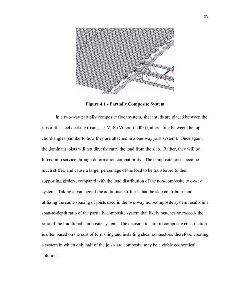
87
Figure 4.1 - Partially Composite System
In a two-way partially composite floor system, shear studs are placed between the
ribs of the steel decking (using 1.5 VLR (Vulcraft 2005)), alternating between the top
chord angles (similar to how they are attached in a one-way joist system). Once again,
the dominant joists will not directly carry the load from the slab. Rather, they will be
forced into service through deformation compatibility. The composite joists become
much stiffer, and cause a larger percentage of the load to be transferred to their
supporting girders, compared with the load distribution of the non-composite two-way
system. Taking advantage of the additional stiffness that the slab contributes and
utilizing the same spacing of joists used in the two-way non-composite system results in a
span-to-depth ratio of the partially composite system that likely matches or exceeds the
ratio of the traditional composite system. The decision to shift to composite construction
is often based on the cost of furnishing and installing shear connectors; therefore, creating
a system in which only half of the joists are composite may be a viable economical
solution.
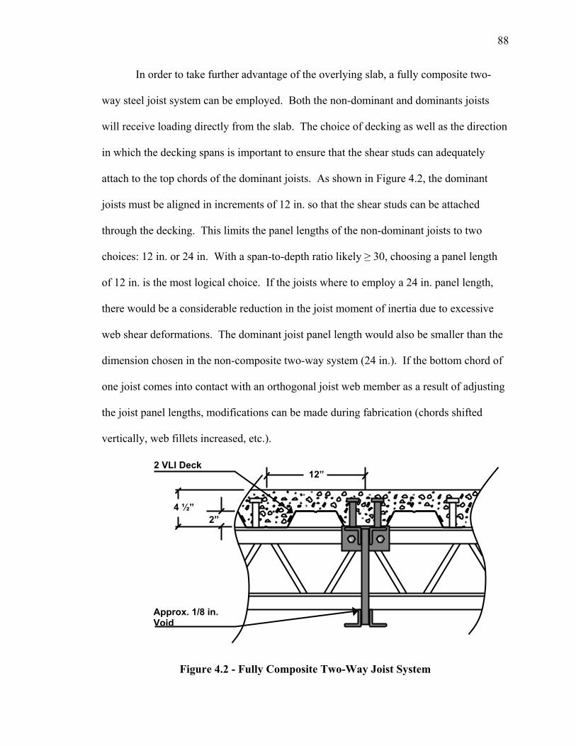
88
In order to take further advantage of the overlying slab, a fully composite two-
way steel joist system can be employed. Both the non-dominant and dominants joists
will receive loading directly from the slab. The choice of decking as well as the direction
in which the decking spans is important to ensure that the shear studs can adequately
attach to the top chords of the dominant joists. As shown in Figure 4.2, the dominant
joists must be aligned in increments of 12 in. so that the shear studs can be attached
through the decking. This limits the panel lengths of the non-dominant joists to two
choices: 12 in. or 24 in. With a span-to-depth ratio likely ≥ 30, choosing a panel length
of 12 in. is the most logical choice. If the joists where to employ a 24 in. panel length,
there would be a considerable reduction in the joist moment of inertia due to excessive
web shear deformations. The dominant joist panel length would also be smaller than the
dimension chosen in the non-composite two-way system (24 in.). If the bottom chord of
one joist comes into contact with an orthogonal joist web member as a result of adjusting
the joist panel lengths, modifications can be made during fabrication (chords shifted
vertically, web fillets increased, etc.).
Figure 4.2 - Fully Composite Two-Way Joist System
4 ½”
2 VLI Deck 12”
2”
Approx. 1/8 in. Void
89
The manner in which loading is distributed throughout a composite system
completely changes when joists spanning in both directions carry the slab. A major
complication arises when trying to quantify the magnitude of loading that each joist
receives from the concrete slab. When carrying wet concrete, the slab will predominantly
span in one direction (parallel to the deck flutes). When the concrete cures the slab will
try to span in two directions depending on the internal reinforcement configuration. The
degree to which it spans in each direction is difficult to quantify in the absence of
experimental testing and significant analytical effort. If the load distribution cannot be
computed within a reasonable degree of certainty, the spacing and sizing of the joists
cannot be determined.
One possible solution to this dilemma is to employ the use of two-way steel
decking. The design philosophy is simple: create steel decking that has ribs aligned
orthogonally so that the deck has ample stiffness and strength in two orthogonal
directions. Overcoming the difficulty of the fabrication of this type of product has yet to
occur. If and when the Steel Deck Institute (SDI) develops two-way decking, a
composite-two-way steel joist system can easily make use of the new technology.
Figure 4.3 shows a plan view of a possible layout of two-way steel decking
overlying a fully composite two-way steel joist system. This configuration assumes that
the two-way steel decking can span 10 ft. in both directions by using unshored
construction. The load distribution is markedly different from the rectangular tributary
areas assumed in a four joist, one-way joist system. The joists in the two-way system
directly carry 66% of the total panel loading, while the joists of a traditional carry 80% of
the panel loading.
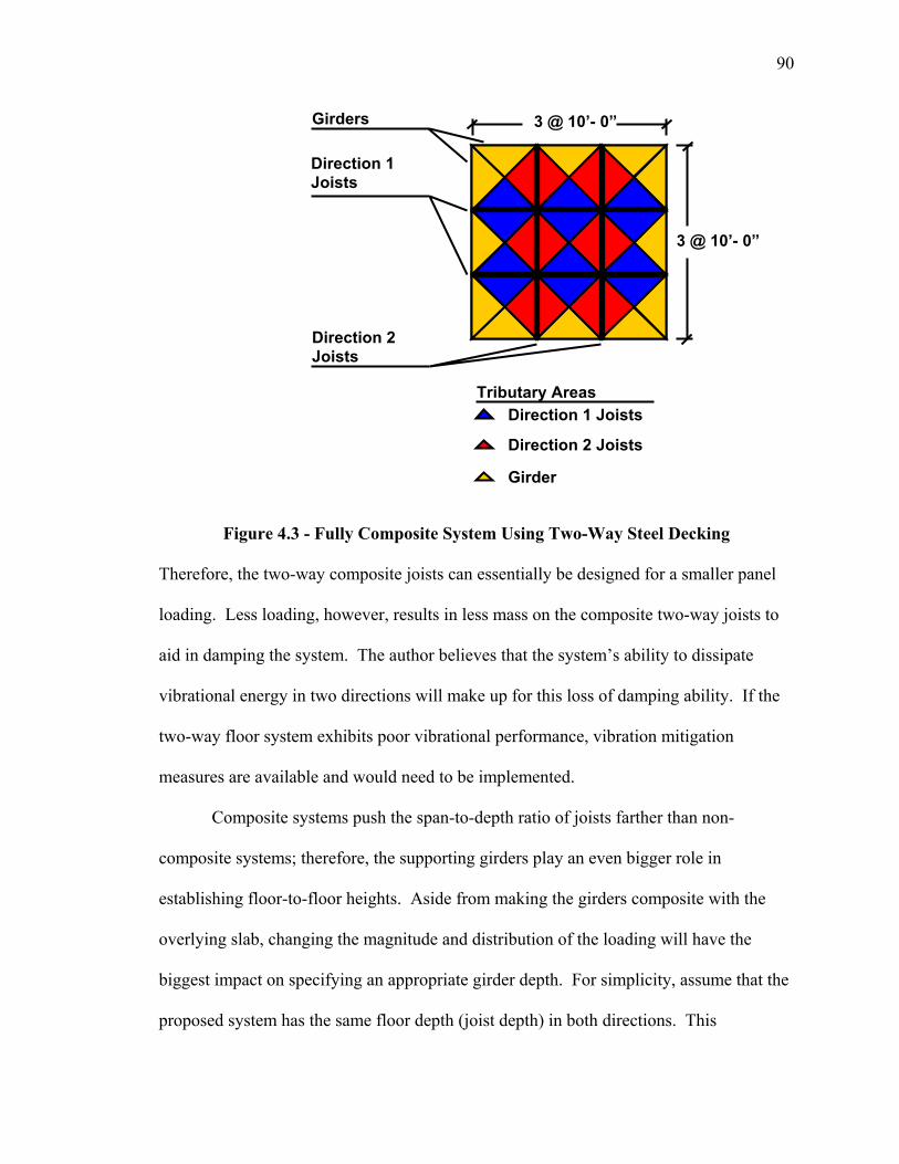
90
Figure 4.3 - Fully Composite System Using Two-Way Steel Decking
Therefore, the two-way composite joists can essentially be designed for a smaller panel
loading. Less loading, however, results in less mass on the composite two-way joists to
aid in damping the system. The author believes that the system’s ability to dissipate
vibrational energy in two directions will make up for this loss of damping ability. If the
two-way floor system exhibits poor vibrational performance, vibration mitigation
measures are available and would need to be implemented.
Composite systems push the span-to-depth ratio of joists farther than non-
composite systems; therefore, the supporting girders play an even bigger role in
establishing floor-to-floor heights. Aside from making the girders composite with the
overlying slab, changing the magnitude and distribution of the loading will have the
biggest impact on specifying an appropriate girder depth. For simplicity, assume that the
proposed system has the same floor depth (joist depth) in both directions. This
Direction 1 Joists
Direction 2 Joists
Girder
Tributary Areas
3 @ 10’- 0”
3 @ 10’- 0”
Direction 1 Joists
Direction 2 Joists
Girders
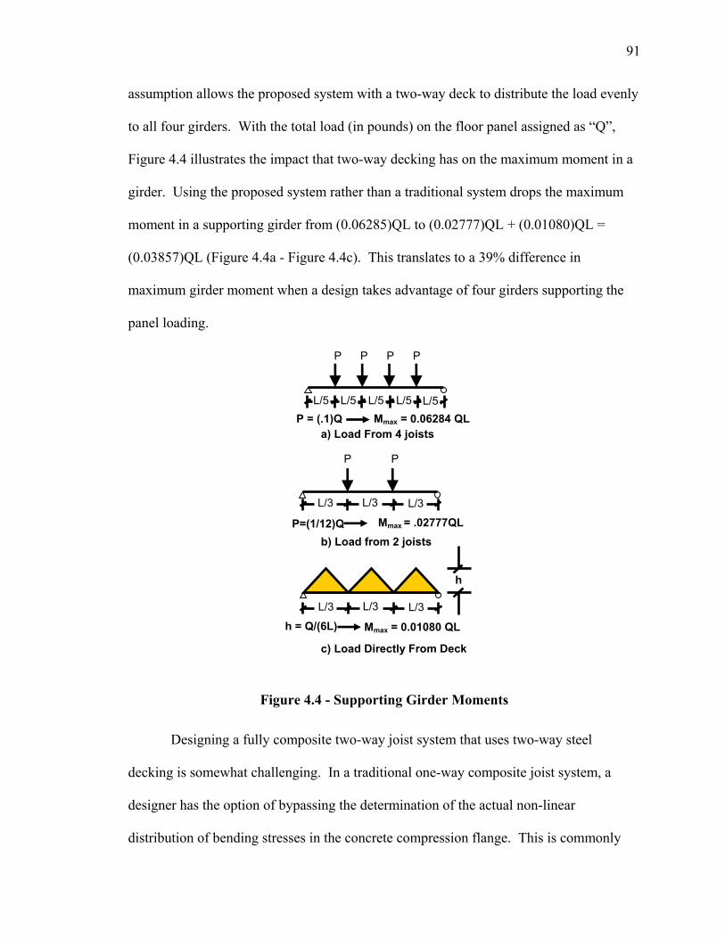
91
assumption allows the proposed system with a two-way deck to distribute the load evenly
to all four girders. With the total load (in pounds) on the floor panel assigned as “Q”,
Figure 4.4 illustrates the impact that two-way decking has on the maximum moment in a
girder. Using the proposed system rather than a traditional system drops the maximum
moment in a supporting girder from (0.06285)QL to (0.02777)QL + (0.01080)QL =
(0.03857)QL (Figure 4.4a - Figure 4.4c). This translates to a 39% difference in
maximum girder moment when a design takes advantage of four girders supporting the
panel loading.
Figure 4.4 - Supporting Girder Moments
Designing a fully composite two-way joist system that uses two-way steel
decking is somewhat challenging. In a traditional one-way composite joist system, a
designer has the option of bypassing the determination of the actual non-linear
distribution of bending stresses in the concrete compression flange. This is commonly
P P
P P P P
h
L/3 L/3 L/3
L/5 L/5 L/5 L/5 L/5
L/3 L/3 L/3
P=(1/12)Q Mmax = .02777QL
P = (.1)Q Mmax = 0.06284 QL
h = Q/(6L) Mmax = 0.01080 QL
b) Load from 2 joists
a) Load From 4 joists
c) Load Directly From Deck
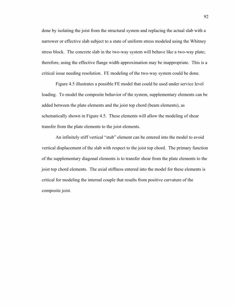
92
done by isolating the joist from the structural system and replacing the actual slab with a
narrower or effective slab subject to a state of uniform stress modeled using the Whitney
stress block. The concrete slab in the two-way system will behave like a two-way plate;
therefore, using the effective flange width approximation may be inappropriate. This is a
critical issue needing resolution. FE modeling of the two-way system could be done.
Figure 4.5 illustrates a possible FE model that could be used under service level
loading. To model the composite behavior of the system, supplementary elements can be
added between the plate elements and the joist top chord (beam elements), as
schematically shown in Figure 4.5. These elements will allow the modeling of shear
transfer from the plate elements to the joist elements.
An infinitely stiff vertical “stub” element can be entered into the model to avoid
vertical displacement of the slab with respect to the joist top chord. The primary function
of the supplementary diagonal elements is to transfer shear from the plate elements to the
joist top chord elements. The axial stiffness entered into the model for these elements is
critical for modeling the internal couple that results from positive curvature of the
composite joist.
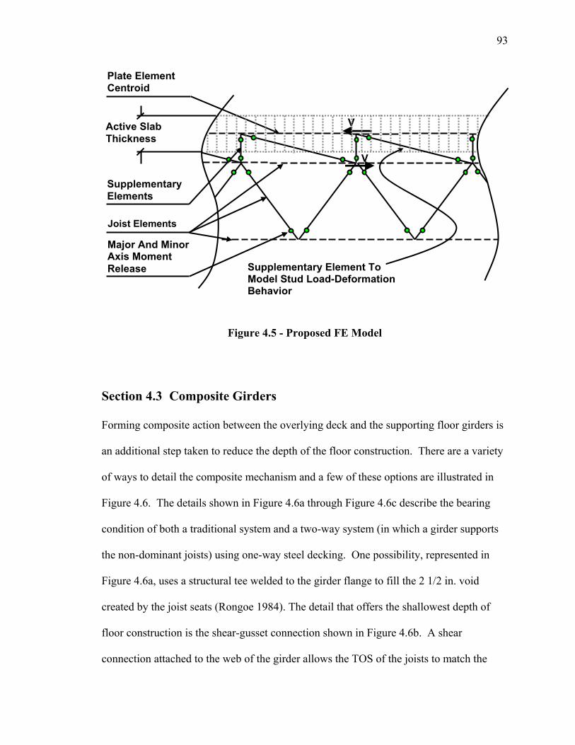
93
Figure 4.5 - Proposed FE Model
Section 4.3 Composite Girders
Forming composite action between the overlying deck and the supporting floor girders is
an additional step taken to reduce the depth of the floor construction. There are a variety
of ways to detail the composite mechanism and a few of these options are illustrated in
Figure 4.6. The details shown in Figure 4.6a through Figure 4.6c describe the bearing
condition of both a traditional system and a two-way system (in which a girder supports
the non-dominant joists) using one-way steel decking. One possibility, represented in
Figure 4.6a, uses a structural tee welded to the girder flange to fill the 2 1/2 in. void
created by the joist seats (Rongoe 1984). The detail that offers the shallowest depth of
floor construction is the shear-gusset connection shown in Figure 4.6b. A shear
connection attached to the web of the girder allows the TOS of the joists to match the
Active Slab Thickness
Supplementary Elements
Plate Element Centroid
V
V
Major And Minor Axis Moment Release Supplementary Element To
Model Stud Load-DeformationBehavior
Joist Elements
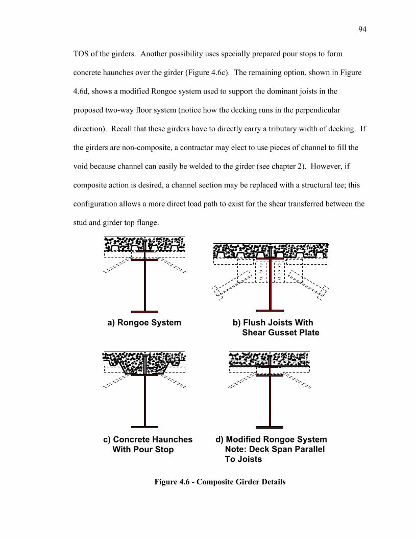
94
TOS of the girders. Another possibility uses specially prepared pour stops to form
concrete haunches over the girder (Figure 4.6c). The remaining option, shown in Figure
4.6d, shows a modified Rongoe system used to support the dominant joists in the
proposed two-way floor system (notice how the decking runs in the perpendicular
direction). Recall that these girders have to directly carry a tributary width of decking. If
the girders are non-composite, a contractor may elect to use pieces of channel to fill the
void because channel can easily be welded to the girder (see chapter 2). However, if
composite action is desired, a channel section may be replaced with a structural tee; this
configuration allows a more direct load path to exist for the shear transferred between the
stud and girder top flange.
Figure 4.6 - Composite Girder Details
a) Rongoe System
c) Concrete Haunches With Pour Stop
d) Modified Rongoe System Note: Deck Span Parallel To Joists
b) Flush Joists With Shear Gusset Plate
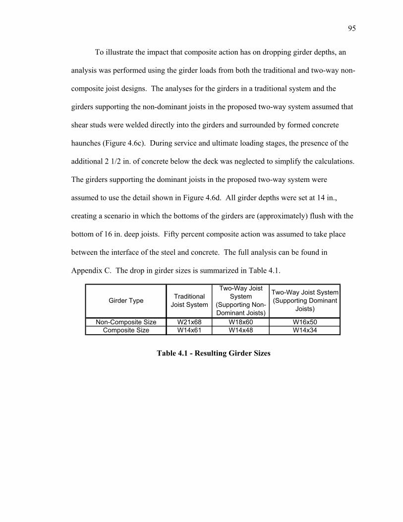
95
To illustrate the impact that composite action has on dropping girder depths, an
analysis was performed using the girder loads from both the traditional and two-way non-
composite joist designs. The analyses for the girders in a traditional system and the
girders supporting the non-dominant joists in the proposed two-way system assumed that
shear studs were welded directly into the girders and surrounded by formed concrete
haunches (Figure 4.6c). During service and ultimate loading stages, the presence of the
additional 2 1/2 in. of concrete below the deck was neglected to simplify the calculations.
The girders supporting the dominant joists in the proposed two-way system were
assumed to use the detail shown in Figure 4.6d. All girder depths were set at 14 in.,
creating a scenario in which the bottoms of the girders are (approximately) flush with the
bottom of 16 in. deep joists. Fifty percent composite action was assumed to take place
between the interface of the steel and concrete. The full analysis can be found in
Appendix C. The drop in girder sizes is summarized in Table 4.1.
Non-Composite Size W21x68 W18x60 W16x50
Composite Size W14x61 W14x48 W14x34
Two-Way Joist System (Supporting Dominant
Joists)Girder Type Traditional
Joist System
Two-Way Joist System
(Supporting Non-Dominant Joists)
Table 4.1 - Resulting Girder Sizes
96
Chapter 5 Conclusions and Recommendations
Section 5.1 Summary
The literature review allowed the reader to reflect upon the more common ways in which
engineers and architects have set out to minimize floor-to-floor heights in commercial
and residential structural steel buildings. In particular, the AISC competition drew
attention to the reality that steel fabricators, erectors, and designers are looking for floor
systems that are shallower and, at the same time, can be categorized as light and easily
able to accommodate MEP conduits. The information in the literature review helped to
mold some of the design concepts used to design the proposed two-way steel joist
system.
A description of the proposed system began with outlining some of the fabrication
issues as well as a general erection sequence that a non-composite two-way floor system
will undertake. Two categories of joists used by this system were defined: dominant
(deeper) and non-dominant (shallower). Three-dimensional solid models of the system
were presented, enabling the reader to quickly survey the critical constituent elements of
the two-way floor system. The author contends that the more simplistic a floor
assembling process becomes (especially in the case of connections), the more willingly
fabricators and erectors will adapt to significant changes in steel floor construction.
The quintessence of the study was examining the structural behavior of the
proposed system, starting with basic plate theory and arriving at the structural behavior of
a non-composite two-way floor system. This chapter outlined the modeling and design
efforts used to select the joist chord and web members, interlocking connections, and
97
supporting girders. The chapter also explained the rationale behind discarding
preliminary system configurations.
The chapter on composite design explained the proposed system must be capable
of becoming composite with the overlying concrete slab in order to emerge as a more
economical alternative to current steel floor construction systems. Three different
composite designs were discussed: partially composite, fully-composite, and fully-
composite with two-way steel decking. Composite girder design was addressed and
accompanied with results illustrating the change in girder depth that occurs when
composite action is used.
Section 5.2 Conclusions
Current joist construction, both composite and non-composite, makes efficient use of
each individual member. Composite construction, in particular, gives a designer the
opportunity to achieve large span-to-depth ratios without developing excessive member
self-weight. The supporting girders in a traditional system, however, can benefit by
changing the manner in which they receive loading, namely, changing the panel from
predominantly spanning in one direction to spanning in two directions. This change is
important because the depth of a girder is included within the depth of the floor
construction.
This study verified that it is structurally feasible to interlock open-web steel joists,
arranged orthogonally within a floor panel, to form a floor system that predominantly
spans in two directions. The system exhibited some structural behavior analogous to
traditional steel joists, while other behavior reflected a uniformly loaded two-way simply
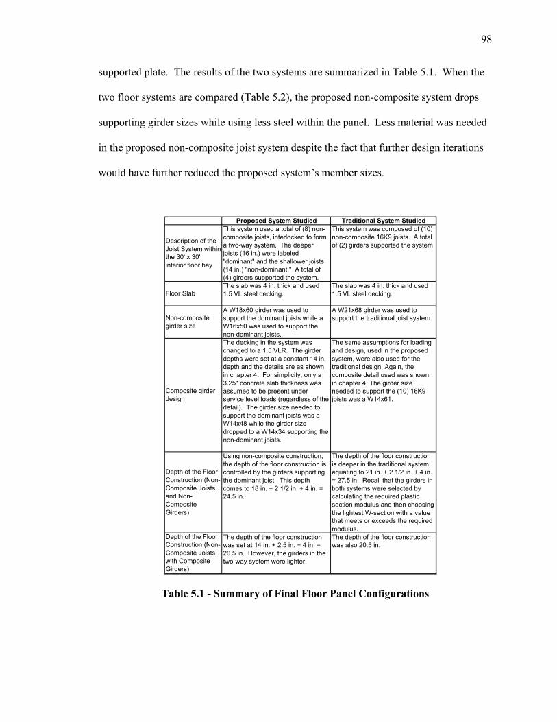
98
supported plate. The results of the two systems are summarized in Table 5.1. When the
two floor systems are compared (Table 5.2), the proposed non-composite system drops
supporting girder sizes while using less steel within the panel. Less material was needed
in the proposed non-composite joist system despite the fact that further design iterations
would have further reduced the proposed system’s member sizes.
Proposed System Studied Traditional System Studied
Depth of the Floor Construction (Non-Composite Joists with Composite Girders)
The depth of the floor construction was set at 14 in. + 2.5 in. + 4 in. = 20.5 in. However, the girders in the two-way system were lighter.
The depth of the floor construction was also 20.5 in.
The depth of the floor construction is deeper in the traditional system, equating to 21 in. + 2 1/2 in. + 4 in. = 27.5 in. Recall that the girders in both systems were selected by calculating the required plastic section modulus and then choosing the lightest W-section with a value that meets or exceeds the required modulus.
Using non-composite construction, the depth of the floor construction is controlled by the girders supporting the dominant joist. This depth comes to 18 in. + 2 1/2 in. + 4 in. = 24.5 in.
Depth of the Floor Construction (Non-Composite Joists and Non-Composite Girders)
A W18x60 girder was used to support the dominant joists while a W16x50 was used to support the non-dominant joists.
A W21x68 girder was used to support the traditional joist system.
The decking in the system was changed to a 1.5 VLR. The girder depths were set at a constant 14 in. depth and the details are as shown in chapter 4. For simplicity, only a 3.25" concrete slab thickness was assumed to be present under service level loads (regardless of the detail). The girder size needed to support the dominant joists was a W14x48 while the girder size dropped to a W14x34 supporting the non-dominant joists.
Composite girder design
The same assumptions for loading and design, used in the proposed system, were also used for the traditional design. Again, the composite detail used was shown in chapter 4. The girder size needed to support the (10) 16K9 joists was a W14x61.
Non-composite girder size
The slab was 4 in. thick and used 1.5 VL steel decking.Floor Slab
The slab was 4 in. thick and used 1.5 VL steel decking.
Description of the Joist System within the 30' x 30' interior floor bay
This system used a total of (8) non-composite joists, interlocked to form a two-way system. The deeper joists (16 in.) were labeled "dominant" and the shallower joists (14 in.) "non-dominant." A total of (4) girders supported the system.
This system was composed of (10) non-composite 16K9 joists. A total of (2) girders supported the system
Table 5.1 - Summary of Final Floor Panel Configurations
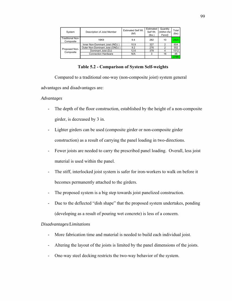
99
Table 5.2 - Comparison of System Self-weights
Compared to a traditional one-way (non-composite joist) system general
advantages and disadvantages are:
Advantages
- The depth of the floor construction, established by the height of a non-composite
girder, is decreased by 3 in.
- Lighter girders can be used (composite girder or non-composite girder
construction) as a result of carrying the panel loading in two-directions.
- Fewer joists are needed to carry the prescribed panel loading. Overall, less joist
material is used within the panel.
- The stiff, interlocked joist system is safer for iron-workers to walk on before it
becomes permanently attached to the girders.
- The proposed system is a big step towards joist panelized construction.
- Due to the deflected “dish shape” that the proposed system undertakes, ponding
(developing as a result of pouring wet concrete) is less of a concern.
Disadvantages/Limitations
- More fabrication time and material is needed to build each individual joist.
- Altering the layout of the joists is limited by the panel dimensions of the joists.
- One-way steel decking restricts the two-way behavior of the system.
Inner Non-Dominant Joist (INDJ ) 10.9 327 2 654Outer Non-Dominant Joist (ONDJ ) 9.2 276 2 552
Dominant Joist (DJ) 12.6 378 4 1512Connection Hardware N/A 3 16 48
2766
Traditional Non-Composite
Proposed Non-Composite
Total (lbs)
16K9 9.4 282 10 2820
Description of Joist MemberSystem Estimated Self Wt. (lbf)
Estimated Self Wt.
(lbs.)
Quantity (Within the
Panel)
100
Section 5.3 Recommendations for Future Research
This study is a first step in a new direction for steel joist floor construction. The focus of
this study was to investigate the structural feasibility of slightly modifying the fabrication
of open-web joists to produce a steel floor system capable of spanning in two directions.
Many additional studies can be undertaken to further verify the practicality of this new
design philosophy.
This study examined a 30’x 30’ ( 1LL
αshort
long == ) floor bay under typical office
loadings. Further studies could provide insight into how varying α from 1≤ α ≤ 2
influences the behavior of the system. Different floor loadings, panel locations (exterior
bay, corner bay, etc.), and floor openings can be investigated to determine the impact of
varying these design parameters.
To act upon the discussion set forth in chapter 4, additional finite element analysis
and experimentation is needed to evaluate composite design. Composite design is likely
to have a significant influence on the behavior of the floor system and the floor system
depth. FE analysis could be used to study load distribution, vibration characteristics,
connection design, and deflections. Experimental work is needed to validate all
analytical efforts. This could involve testing the bolted connection components or going
as far as testing the entire system at full-scale.
A floor system must exhibit satisfactory vibrational performance in order to gain
acceptance among architects and contractors. This study examined only the static
structural characteristics of the proposed system. Further analysis is required to
determine whether or not the system would meet vibrational performance standards under
dynamic loading.

101
Finally, and perhaps most importantly, the results of an economical evaluation are
necessary for the development of this system. This evaluation should not only include
comparisons with open-web steel joist, but also with other floor framing systems
(including concrete floor systems). Once the design of a two-way steel floor system
using open-web steel joists becomes established, computer algorithms could be
developed to determine the most effective joist configurations.
102
References
ACI. (2002). Building Code Requirements for Structural Concrete (ACI 318-02) and
Commentary (ACI 318R-02), American Concrete Institute, Farmington Hills, MI.
Ahmad, M., Chien, E. Y. L., and Hosain, M. U. (1992). "Modified Stub-Girder Floor
System: Full-Scale Tests." Journal of Structural Engineering, 118(11), 3222-
3236.
AISC. (2001a). 3rd Edition LRFD Manual of Steel Construction, American Institute of
Steel Construction, Chicago, IL.
AISC. (2001b). Load and Resistance Factor Design Specifications for Structural Steel
Buildings, American Institute of Steel Construction, Chicago, IL.
AISC (2004) AISC Multi-Story Residential Competition,
http://www.aisc.org/Template.cfm?Section=Press_Releases1&template=/PressRel
ease/PressReleaseDisplay.cfm&PressReleaseID=50119&PressReleaseCategoryID
=1&ShowArchives=0, Last Accessed in June, 2005.
ASCE. (1996). "Proposed Specification and Commentary for Composite Joists and
Composite Trusses." Journal of Structural Engineering(April), 350-358.
Atkinson, A. H., Cran, J. A. "The Design and Economics of Composite Open-Web Steel
Joists." Canadian Structural Engineering Conference.
Azmi, M. H. (1972). "Composite Open-Web Trusses with Metal Cellular Floor," A
Master of Engineering Thesis, McMaster University, Hamilton, Ontario.
Boresi, A. P., Schmidt, R. J., Sidebottom, O. M. (1993). Advanced Mechanics of
Materials, John Wiley & Sons.
103
Brattland, A., Kennedy, D. J. L. (1992). "Flexural Tests of Two Full-Scale Composite
Trusses." Canadian Journal of Civil Engineering, 19(2), 279-295.
Canam (2005) Canam Group, Inc., http://www.canamsteel.com, Last Accessed in June,
2005.
Chien, E. Y. L., Ritchie, J. K. (1993). "Composite Floor Systems-A Mature Design
Option." Journal of Constructural Steel Research, 25(1-2), 107-139.
Cohen, M. P. (1986). "Design Solutions Utilizing the Staggered-steel Truss System."
AISC Engineering Journal(3rd Quarter), 97-106.
Colaco, J. P. (1972). "A Stub-Girder System for High-Rise Buildings." AISC Engineering
Journal, 89-95.
Cross, J. (2003). "Coordinated Construction." Modern Steel Construction(July).
CSI. (2004). SAP2000 Linear and Nonlinear Static and Dynamic Analysis and Design of
Three - Dimensional Structures, Computers & Structures, Inc., Berkeley, CA.
Curry, J. H. (1988). "Full Scale Tests on Two Long-Span Composite Open-Web Steel
Joists," Masters Thesis, University of Minnesota, MN.
El-Sheikh, A. (2000). "New SpaceTruss System -From Concept to Implementation."
Engineering Structures, 22, 1070-1085.
El-Sheikh, A., McConnel R. E. (1993). "Experimental Study of Behavior of Composite
Space Trusses." Journal of Structural Engineering, 119(3), 747-766.
Fang, P. J. (1968). "Test on Diaphragm Behavior of Dry-Floor System with Steel-Edged
Gypsum Planks." AISC Engineering Journal(January).
Fenster, S. K., Ugural, A. C. (2003). Advanced Strength and Applied Elasticity, Prentice
Hall Professional Technical Reference.
104
Galambos, T. V., Tide, R. H. R. (1970). "Composite Open-Web Steel Joists." AISC
Engineering Journal(January).
Girder-Slab (2005a) Girder-Slab System, http://www.girder-
slab.com/diagram/system_diagram.asp, Last Accessed in 2005.
Girder-Slab (2005b) Gooseneck Connection, http://www.girder-
slab.com/Modern_Steel_Construction_May_2002.pdf, Last Accessed in 2005.
Hambro (2005) Canam Group, Inc., http://www.hambrosystems.com, Last Accessed in
June, 2005.
Hassett, P. (2004). "Stiffened Plate Floor Deck." Hassett Engineering, Inc., Castor
Valley.
Itzler, K. (2004). "Structural Steel/ Autoclaved Aerated Concrete (AAC) Composite
Floor Systems." Dewbery-Goodkind, Inc., New York.
Kirmani, M. (2000). "Achieving Low Floor-to-Floor Heights." Modern Steel
Construction.
Lembeck, H. G. (1965). "Composite Design of Open-web Steel Joists," M.Sc.,
Washington University, St. Louis MO.
Leon, R. T., Curry, J. "Behavior of Long Span Composite Joists." ASCE Structures
Congress Proceedings, Florida, 390-403.
Murray, T. M., Allen, D., and Ungar, E. (1997). "Floor Vibrations Due to Human
Activity." Steel Design Guide Series 11, AISC, Chicago, IL.
Naccarato, P. A. (1999). "New Alternative to Flat Plate Construction." Modern Steel
Construction.
105
Naccarato, P. A. (2000). "Superstructure Completed in Just Eight Weeks." Modern Steel
Construction(Sept.), 40-44.
Naccarato, P. A. (2001). "Steel & Precast Slab Construction System for Mid and High-
Rise Residential Buildings." Modern Steel Construction.
Newman, J. H. (1966). "The Dry Floor - A New Approach to High Rise Apartment
Buildings." AISC Engineering Journal.
Nilson, A. H., Winter, G. (1991). Design of Concrete Structures, McGraw - Hill.
Robinson, H., Fahmy, E. H. (1978). "The Design of Partially Connected Composite
Open-Web Joists." Canadian Journal of Civil Engineering, 5, 611-614.
Rongoe, J. (1984). "A Composite Girder System for Joist Supported Slabs." AISC
Engineering Journal(3rd Quarter), 155-160.
Samuelson, D. (2002). "Composite Steel Joists." AISC Engineering Journal(Third
Quarter), 111-120.
Samuelson, D. (2003). "Composite Joist Advantage." Modern Steel Construction,
September.
Samuleson (2005) Personal Communication with J. Schaad.
Scalzi, J. B. (1971). "The Staggered-truss System - Structural Considerations." AISC
Engineering Journal, 138-143.
SJI. (2005). Standard Specifications Load Tables and Weight Tables For Steel Joist and
Joist Girders.
SMI (2005) SMI Steel Products, http://www.smijoist.com/, Last Accessed in June, 2005.
Veitas, R. (2002). "Slab Solution." Modern Steel Construction.
106
Vescom (2005) Vescom Structures, Inc., http://www.vescomstructures.com/, Last
Accessed in June, 2005.
Vinnakota, S. (2005). Steel Structures: Behavior and LRFD, McGraw - Hill.
Vulcraft (2005) Vulcraft - Division of NUCOR, http://www.vulcraft.com, Last Accessed
in June, 2005.
Wang, C. M., Padmanaban, K., and Shanmugam, N. E. (1995). "Ultimate Strength
Analysis of Stub Girders." Journal of Structural Engineering, 1259-1264.

107
Appendix A
The following tables and figures illustrate the joist member sizes chosen for the proposed
two-way joist system that uses allowable stress design. Taking advantage of symmetry,
the labeling scheme is shown in Figure A.1. The numbering shown in Figure A.1a takes
advantage of symmetry to identify each top chord, bottom chord, and web member in the
proposed system. Even though the design distinguishes between two types of non-
dominant joists (outer non-dominant joists and inner non-dominant joists), Figure A.1b is
valid for both types. The equations used were outlined in Chapter 3.
Figure A.1 - Joist Labeling
1 2 3 4 5 6 7 8 9
10 11 12 13 14 15 16 17 18 19
20 21 22
23
24
25 26
27
28
29 30 31 32
33
34
35 36
37
38
39 40
1 2 3 4 5 6 7 8 9
10 11 12 13 14 15 16 17
19 18 21 23 25 27 29 31 33
20 22 24 26 28 30 32 34
a) Dominant Joist
b) Non-Dominant Joist
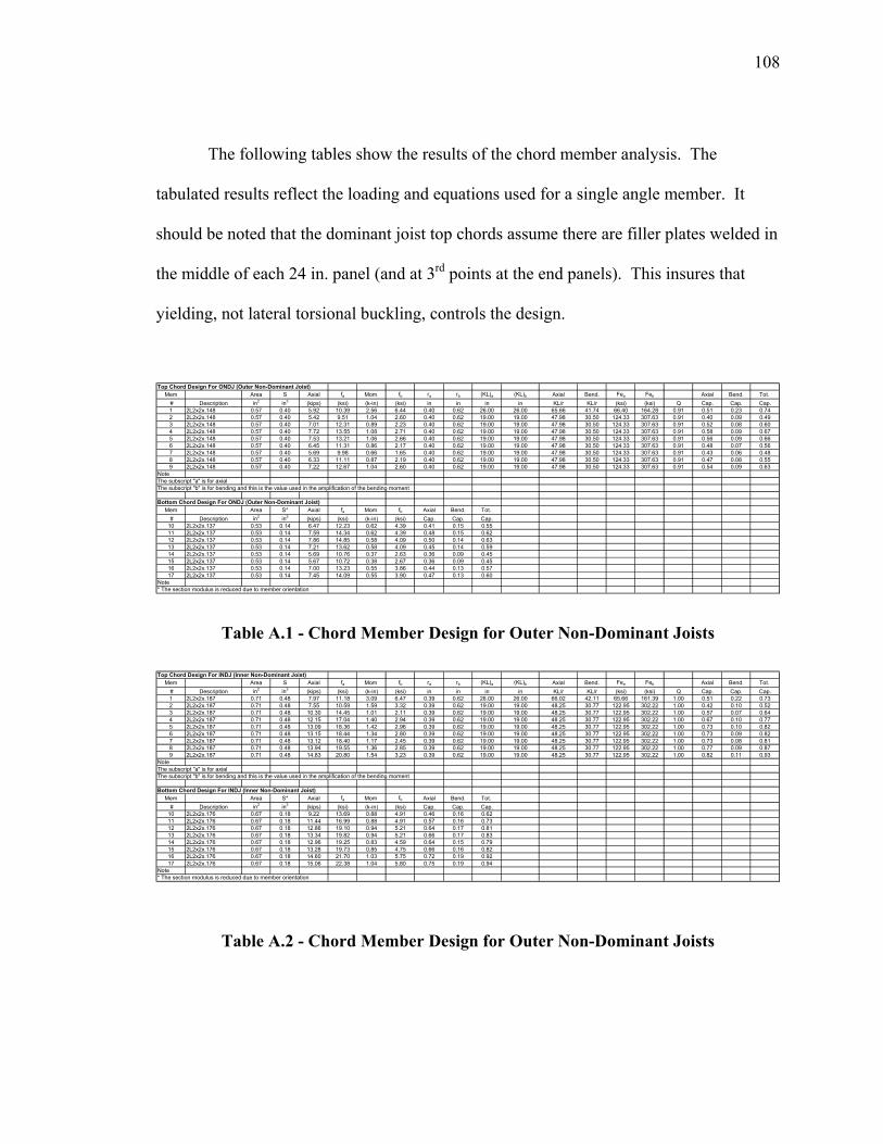
108
The following tables show the results of the chord member analysis. The
tabulated results reflect the loading and equations used for a single angle member. It
should be noted that the dominant joist top chords assume there are filler plates welded in
the middle of each 24 in. panel (and at 3rd points at the end panels). This insures that
yielding, not lateral torsional buckling, controls the design.
Top Chord Design For ONDJ (Outer Non-Dominant Joist)Mem Area S Axial fa Mom fb ra rb (KL)a (KL)b Axial Bend. Fea Feb Axial Bend. Tot.
# Description in2 in3 (kips) (ksi) (k-in) (ksi) in in in in KL/r KL/r (ksi) (ksi) Q Cap. Cap. Cap.1 2L2x2x.148 0.57 0.40 5.92 10.39 2.56 6.44 0.40 0.62 26.00 26.00 65.66 41.74 66.40 164.28 0.91 0.51 0.23 0.742 2L2x2x.148 0.57 0.40 5.42 9.51 1.04 2.60 0.40 0.62 19.00 19.00 47.98 30.50 124.33 307.63 0.91 0.40 0.09 0.493 2L2x2x.148 0.57 0.40 7.01 12.31 0.89 2.23 0.40 0.62 19.00 19.00 47.98 30.50 124.33 307.63 0.91 0.52 0.08 0.604 2L2x2x.148 0.57 0.40 7.72 13.55 1.08 2.71 0.40 0.62 19.00 19.00 47.98 30.50 124.33 307.63 0.91 0.58 0.09 0.675 2L2x2x.148 0.57 0.40 7.53 13.21 1.06 2.66 0.40 0.62 19.00 19.00 47.98 30.50 124.33 307.63 0.91 0.56 0.09 0.666 2L2x2x.148 0.57 0.40 6.45 11.31 0.86 2.17 0.40 0.62 19.00 19.00 47.98 30.50 124.33 307.63 0.91 0.48 0.07 0.567 2L2x2x.148 0.57 0.40 5.69 9.98 0.66 1.65 0.40 0.62 19.00 19.00 47.98 30.50 124.33 307.63 0.91 0.43 0.06 0.488 2L2x2x.148 0.57 0.40 6.33 11.11 0.87 2.19 0.40 0.62 19.00 19.00 47.98 30.50 124.33 307.63 0.91 0.47 0.08 0.559 2L2x2x.148 0.57 0.40 7.22 12.67 1.04 2.60 0.40 0.62 19.00 19.00 47.98 30.50 124.33 307.63 0.91 0.54 0.09 0.63
NoteThe subscript "a" is for axialThe subscript "b" is for bending and this is the value used in the amplification of the bending moment
Bottom Chord Design For ONDJ (Outer Non-Dominant Joist)Mem Area S* Axial fa Mom fb Axial Bend. Tot.
# Description in2 in3 (kips) (ksi) (k-in) (ksi) Cap. Cap. Cap.10 2L2x2x.137 0.53 0.14 6.47 12.23 0.62 4.39 0.41 0.15 0.5511 2L2x2x.137 0.53 0.14 7.59 14.34 0.62 4.39 0.48 0.15 0.6212 2L2x2x.137 0.53 0.14 7.86 14.85 0.58 4.09 0.50 0.14 0.6313 2L2x2x.137 0.53 0.14 7.21 13.62 0.58 4.09 0.45 0.14 0.5914 2L2x2x.137 0.53 0.14 5.69 10.76 0.37 2.63 0.36 0.09 0.4515 2L2x2x.137 0.53 0.14 5.67 10.72 0.38 2.67 0.36 0.09 0.4516 2L2x2x.137 0.53 0.14 7.00 13.23 0.55 3.86 0.44 0.13 0.5717 2L2x2x.137 0.53 0.14 7.45 14.09 0.55 3.90 0.47 0.13 0.60
Note* The section modulus is reduced due to member orientation
Table A.1 - Chord Member Design for Outer Non-Dominant Joists Top Chord Design For INDJ (Inner Non-Dominant Joist)
Mem Area S Axial fa Mom fb ra rb (KL)a (KL)b Axial Bend. Fea Feb Axial Bend. Tot. # Description in2 in3 (kips) (ksi) (k-in) (ksi) in in in in KL/r KL/r (ksi) (ksi) Q Cap. Cap. Cap.1 2L2x2x.187 0.71 0.48 7.97 11.18 3.09 6.47 0.39 0.62 26.00 26.00 66.02 42.11 65.66 161.39 1.00 0.51 0.22 0.732 2L2x2x.187 0.71 0.48 7.55 10.59 1.59 3.32 0.39 0.62 19.00 19.00 48.25 30.77 122.95 302.22 1.00 0.42 0.10 0.523 2L2x2x.187 0.71 0.48 10.30 14.45 1.01 2.11 0.39 0.62 19.00 19.00 48.25 30.77 122.95 302.22 1.00 0.57 0.07 0.644 2L2x2x.187 0.71 0.48 12.15 17.04 1.40 2.94 0.39 0.62 19.00 19.00 48.25 30.77 122.95 302.22 1.00 0.67 0.10 0.775 2L2x2x.187 0.71 0.48 13.09 18.36 1.42 2.96 0.39 0.62 19.00 19.00 48.25 30.77 122.95 302.22 1.00 0.73 0.10 0.826 2L2x2x.187 0.71 0.48 13.15 18.44 1.34 2.80 0.39 0.62 19.00 19.00 48.25 30.77 122.95 302.22 1.00 0.73 0.09 0.827 2L2x2x.187 0.71 0.48 13.12 18.40 1.17 2.45 0.39 0.62 19.00 19.00 48.25 30.77 122.95 302.22 1.00 0.73 0.08 0.818 2L2x2x.187 0.71 0.48 13.94 19.55 1.36 2.85 0.39 0.62 19.00 19.00 48.25 30.77 122.95 302.22 1.00 0.77 0.09 0.879 2L2x2x.187 0.71 0.48 14.83 20.80 1.54 3.23 0.39 0.62 19.00 19.00 48.25 30.77 122.95 302.22 1.00 0.82 0.11 0.93
NoteThe subscript "a" is for axialThe subscript "b" is for bending and this is the value used in the amplification of the bending moment
Bottom Chord Design For INDJ (Inner Non-Dominant Joist)Mem Area S* Axial fa Mom fb Axial Bend. Tot.
# Description in2 in3 (kips) (ksi) (k-in) (ksi) Cap. Cap. Cap.10 2L2x2x.176 0.67 0.18 9.22 13.69 0.88 4.91 0.46 0.16 0.6211 2L2x2x.176 0.67 0.18 11.44 16.99 0.88 4.91 0.57 0.16 0.7312 2L2x2x.176 0.67 0.18 12.86 19.10 0.94 5.21 0.64 0.17 0.8113 2L2x2x.176 0.67 0.18 13.34 19.82 0.94 5.21 0.66 0.17 0.8314 2L2x2x.176 0.67 0.18 12.96 19.25 0.83 4.59 0.64 0.15 0.7915 2L2x2x.176 0.67 0.18 13.28 19.73 0.85 4.75 0.66 0.16 0.8216 2L2x2x.176 0.67 0.18 14.60 21.70 1.03 5.75 0.72 0.19 0.9217 2L2x2x.176 0.67 0.18 15.06 22.38 1.04 5.80 0.75 0.19 0.94
Note* The section modulus is reduced due to member orientation
Table A.2 - Chord Member Design for Outer Non-Dominant Joists
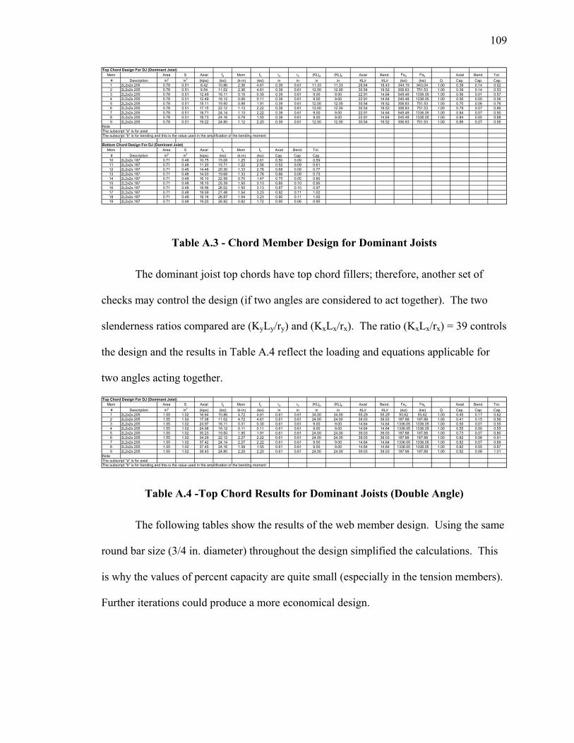
109
Top Chord Design For DJ (Dominant Joist)Mem Area S Axial fa Mom fb ra rb (KL)a (KL)b Axial Bend. Fea Feb Axial Bend. Tot.
# Description in2 in3 (kips) (ksi) (k-in) (ksi) in in in in KL/r KL/r (ksi) (ksi) Q Cap. Cap. Cap.1 2L2x2x.205 0.78 0.51 8.42 10.86 2.36 4.61 0.39 0.61 11.33 11.33 28.84 18.43 344.19 843.04 1.00 0.38 0.14 0.522 2L2x2x.205 0.78 0.51 8.54 11.02 2.36 4.61 0.39 0.61 12.00 12.00 30.54 19.52 306.83 751.53 1.00 0.39 0.14 0.533 2L2x2x.205 0.78 0.51 12.49 16.11 0.15 0.30 0.39 0.61 9.00 9.00 22.91 14.64 545.48 1336.05 1.00 0.56 0.01 0.574 2L2x2x.205 0.78 0.51 12.49 16.12 0.06 0.11 0.39 0.61 9.00 9.00 22.91 14.64 545.48 1336.05 1.00 0.56 0.00 0.565 2L2x2x.205 0.78 0.51 15.11 19.50 0.98 1.91 0.39 0.61 12.00 12.00 30.54 19.52 306.83 751.53 1.00 0.70 0.06 0.766 2L2x2x.205 0.78 0.51 17.15 22.12 1.13 2.22 0.39 0.61 12.00 12.00 30.54 19.52 306.83 751.53 1.00 0.79 0.07 0.867 2L2x2x.205 0.78 0.51 18.71 24.14 1.13 2.22 0.39 0.61 9.00 9.00 22.91 14.64 545.48 1336.05 1.00 0.84 0.07 0.908 2L2x2x.205 0.78 0.51 18.73 24.16 0.79 1.55 0.39 0.61 9.00 9.00 22.91 14.64 545.48 1336.05 1.00 0.84 0.05 0.889 2L2x2x.205 0.78 0.51 19.22 24.80 1.12 2.20 0.39 0.61 12.00 12.00 30.54 19.52 306.83 751.53 1.00 0.88 0.07 0.95
NoteThe subscript "a" is for axialThe subscript "b" is for bending and this is the value used in the amplification of the bending moment
Bottom Chord Design For DJ (Dominant Joist)Mem Area S Axial fa Mom fb Axial Bend. Tot.
# Description in2 in3 (kips) (ksi) (k-in) (ksi) Cap. Cap. Cap.10 2L2x2x.187 0.71 0.48 10.75 15.08 1.25 2.61 0.50 0.09 0.5911 2L2x2x.187 0.71 0.48 11.20 15.71 1.22 2.56 0.52 0.09 0.6112 2L2x2x.187 0.71 0.48 14.48 20.30 1.33 2.78 0.68 0.09 0.7713 2L2x2x.187 0.71 0.48 14.03 19.68 1.33 2.78 0.66 0.09 0.7514 2L2x2x.187 0.71 0.48 16.10 22.58 0.70 1.47 0.75 0.05 0.8015 2L2x2x.187 0.71 0.48 18.10 25.39 1.50 3.13 0.85 0.10 0.9516 2L2x2x.187 0.71 0.48 18.56 26.02 1.50 3.13 0.87 0.10 0.9717 2L2x2x.187 0.71 0.48 19.59 27.48 1.54 3.23 0.92 0.11 1.0218 2L2x2x.187 0.71 0.48 19.16 26.87 1.54 3.23 0.90 0.11 1.0019 2L2x2x.187 0.71 0.48 19.20 26.92 0.82 1.72 0.90 0.06 0.95
Table A.3 - Chord Member Design for Dominant Joists
The dominant joist top chords have top chord fillers; therefore, another set of
checks may control the design (if two angles are considered to act together). The two
slenderness ratios compared are (KyLy/ry) and (KxLx/rx). The ratio (KxLx/rx) = 39 controls
the design and the results in Table A.4 reflect the loading and equations applicable for
two angles acting together.
Top Chord Design For DJ (Dominant Joist)Mem Area S Axial fa Mom fb ra rb (KL)a (KL)b Axial Bend. Fea Feb Axial Bend. Tot.
# Description in2 in3 (kips) (ksi) (k-in) (ksi) in in in in KL/r KL/r (ksi) (ksi) Q Cap. Cap. Cap.1 2L2x2x.205 1.55 1.02 16.84 10.86 4.72 4.61 0.61 0.61 34.00 34.00 55.29 55.29 93.62 93.62 1.00 0.45 0.17 0.622 2L2x2x.205 1.55 1.02 17.08 11.02 4.72 4.61 0.61 0.61 24.00 24.00 39.03 39.03 187.88 187.88 1.00 0.41 0.15 0.563 2L2x2x.205 1.55 1.02 24.97 16.11 0.31 0.30 0.61 0.61 9.00 9.00 14.64 14.64 1336.05 1336.05 1.00 0.55 0.01 0.554 2L2x2x.205 1.55 1.02 24.98 16.12 0.11 0.11 0.61 0.61 9.00 9.00 14.64 14.64 1336.05 1336.05 1.00 0.55 0.00 0.555 2L2x2x.205 1.55 1.02 30.23 19.50 1.95 1.91 0.61 0.61 24.00 24.00 39.03 39.03 187.88 187.88 1.00 0.73 0.07 0.806 2L2x2x.205 1.55 1.02 34.29 22.12 2.27 2.22 0.61 0.61 24.00 24.00 39.03 39.03 187.88 187.88 1.00 0.82 0.08 0.917 2L2x2x.205 1.55 1.02 37.42 24.14 2.27 2.22 0.61 0.61 9.00 9.00 14.64 14.64 1336.05 1336.05 1.00 0.82 0.07 0.898 2L2x2x.205 1.55 1.02 37.45 24.16 1.59 1.55 0.61 0.61 9.00 9.00 14.64 14.64 1336.05 1336.05 1.00 0.82 0.05 0.879 2L2x2x.205 1.55 1.02 38.43 24.80 2.25 2.20 0.61 0.61 24.00 24.00 39.03 39.03 187.88 187.88 1.00 0.92 0.08 1.01
NoteThe subscript "a" is for axialThe subscript "b" is for bending and this is the value used in the amplification of the bending moment
Table A.4 -Top Chord Results for Dominant Joists (Double Angle)
The following tables show the results of the web member design. Using the same
round bar size (3/4 in. diameter) throughout the design simplified the calculations. This
is why the values of percent capacity are quite small (especially in the tension members).
Further iterations could produce a more economical design.
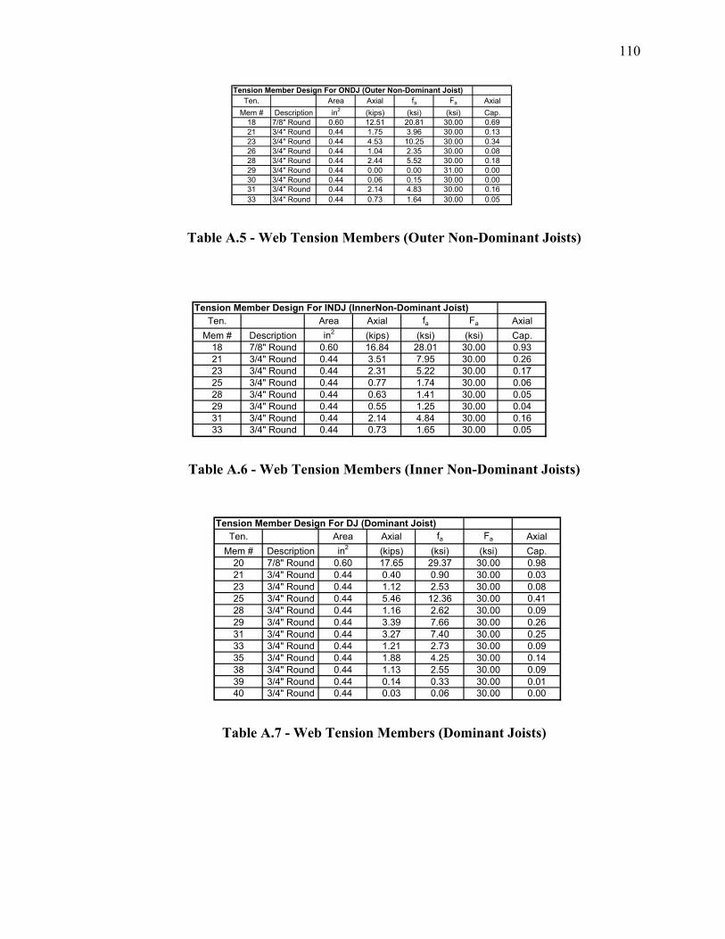
110
Tension Member Design For ONDJ (Outer Non-Dominant Joist)Ten. Area Axial fa Fa Axial
Mem # Description in2 (kips) (ksi) (ksi) Cap.18 7/8" Round 0.60 12.51 20.81 30.00 0.6921 3/4" Round 0.44 1.75 3.96 30.00 0.1323 3/4" Round 0.44 4.53 10.25 30.00 0.3426 3/4" Round 0.44 1.04 2.35 30.00 0.0828 3/4" Round 0.44 2.44 5.52 30.00 0.1829 3/4" Round 0.44 0.00 0.00 31.00 0.0030 3/4" Round 0.44 0.06 0.15 30.00 0.0031 3/4" Round 0.44 2.14 4.83 30.00 0.1633 3/4" Round 0.44 0.73 1.64 30.00 0.05
Table A.5 - Web Tension Members (Outer Non-Dominant Joists)
Tension Member Design For INDJ (InnerNon-Dominant Joist)Ten. Area Axial fa Fa Axial
Mem # Description in2 (kips) (ksi) (ksi) Cap.18 7/8" Round 0.60 16.84 28.01 30.00 0.9321 3/4" Round 0.44 3.51 7.95 30.00 0.2623 3/4" Round 0.44 2.31 5.22 30.00 0.1725 3/4" Round 0.44 0.77 1.74 30.00 0.0628 3/4" Round 0.44 0.63 1.41 30.00 0.0529 3/4" Round 0.44 0.55 1.25 30.00 0.0431 3/4" Round 0.44 2.14 4.84 30.00 0.1633 3/4" Round 0.44 0.73 1.65 30.00 0.05
Table A.6 - Web Tension Members (Inner Non-Dominant Joists)
Tension Member Design For DJ (Dominant Joist)Ten. Area Axial fa Fa Axial
Mem # Description in2 (kips) (ksi) (ksi) Cap.20 7/8" Round 0.60 17.65 29.37 30.00 0.9821 3/4" Round 0.44 0.40 0.90 30.00 0.0323 3/4" Round 0.44 1.12 2.53 30.00 0.0825 3/4" Round 0.44 5.46 12.36 30.00 0.4128 3/4" Round 0.44 1.16 2.62 30.00 0.0929 3/4" Round 0.44 3.39 7.66 30.00 0.2631 3/4" Round 0.44 3.27 7.40 30.00 0.2533 3/4" Round 0.44 1.21 2.73 30.00 0.0935 3/4" Round 0.44 1.88 4.25 30.00 0.1438 3/4" Round 0.44 1.13 2.55 30.00 0.0939 3/4" Round 0.44 0.14 0.33 30.00 0.0140 3/4" Round 0.44 0.03 0.06 30.00 0.00
Table A.7 - Web Tension Members (Dominant Joists)
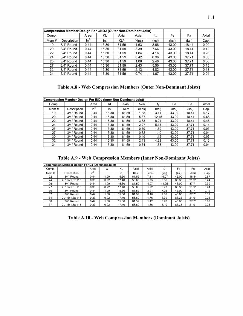
111
Compression Member Design For ONDJ (Outer Non-Dominant Joist)Comp. Area KL Axial Axial fa Fe Fa AxialMem # Description in2 in. KL/r (kips) (ksi) (ksi) (ksi) Cap.
19 3/4" Round 0.44 15.30 81.59 1.63 3.68 43.00 18.44 0.2020 3/4" Round 0.44 15.30 81.59 3.39 7.66 43.00 18.44 0.4222 3/4" Round 0.44 15.30 81.59 1.84 4.16 43.00 18.44 0.2324 3/4" Round 0.44 15.30 81.59 0.42 0.96 43.00 37.71 0.0325 3/4" Round 0.44 15.30 81.59 1.06 2.40 43.00 37.71 0.0627 3/4" Round 0.44 15.30 81.59 2.43 5.50 43.00 37.71 0.1532 3/4" Round 0.44 15.30 81.59 2.13 4.82 43.00 37.71 0.1334 3/4" Round 0.44 15.30 81.59 0.74 1.67 43.00 37.71 0.04
Table A.8 - Web Compression Members (Outer Non-Dominant Joists)
Compression Member Design For INDJ (Inner Non-Dominant Joist)Comp. Area KL Axial Axial fa Fe Fa AxialMem # Description in2 in. KL/r (kips) (ksi) (ksi) (ksi) Cap.
19 3/4" Round 0.44 15.30 81.59 1.38 3.11 43.00 18.44 0.1720 3/4" Round 0.44 15.30 81.59 5.37 12.15 43.00 18.44 0.6622 3/4" Round 0.44 15.30 81.59 3.63 8.21 43.00 18.44 0.4524 3/4" Round 0.44 15.30 81.59 2.27 5.13 43.00 37.71 0.1426 3/4" Round 0.44 15.30 81.59 0.79 1.79 43.00 37.71 0.0527 3/4" Round 0.44 15.30 81.59 0.62 1.40 43.00 37.71 0.0430 3/4" Round 0.44 15.30 81.59 0.49 1.12 43.00 37.71 0.0332 3/4" Round 0.44 15.30 81.59 2.13 4.82 43.00 37.71 0.1334 3/4" Round 0.44 15.30 81.59 0.74 1.68 43.00 37.71 0.04
Table A.9 - Web Compression Members (Inner Non-Dominant Joists) Compression Member Design For DJ (Dominant Joist)
Comp. Area Q KL Axial Axial fa Fe Fa AxialMem # Description in2 in. KL/r (kips) (ksi) (ksi) (ksi) Cap.
22 3/4" Round 0.44 1.00 15.30 81.59 7.11 16.07 43.00 18.44 0.8724 2L1.5x1.5x.113 0.33 0.92 17.40 58.60 1.75 5.36 83.35 21.91 0.2426 3/4" Round 0.44 1.00 15.30 81.59 4.97 11.25 43.00 37.71 0.3027 2L1.5x1.5x.113 0.33 0.92 17.40 58.60 1.72 5.27 83.35 21.91 0.2430 3/4" Round 0.44 1.00 15.30 81.59 3.21 7.26 43.00 37.71 0.1932 3/4" Round 0.44 1.00 15.30 81.59 3.10 7.02 43.00 37.71 0.1934 2L1.5x1.5x.113 0.33 0.92 17.40 58.60 1.76 5.39 83.35 21.91 0.2536 3/4" Round 0.44 1.00 15.30 81.59 1.42 3.20 43.00 37.71 0.0837 2L1.5x1.5x.113 0.33 0.92 17.40 58.60 1.66 5.10 83.35 21.91 0.23
Table A.10 - Web Compression Members (Dominant Joists)
112
Appendix B The following calculations are for a joist and non-composite girder design of a 30 ft. x 30
ft. traditional interior floor bay panel.
Description:
The girder supports reactions from two adjacent floors bays composed of (10) 16 K9 non-
composite joists. The panel has a 4 in. concrete (4 ksi) floor slab. All girders are grade
50 steel.
Loadings:
SI DL = 40 psf (4 in. slab using 1.5 VLI composite decking (Vulcraft 2005))
15 psf (plumbing, electrical, and ceiling)
SI LL = 50 psf (office)
15 psf (partition loading)
Assumptions:
- At the ultimate load stage (girder design), the load combination 1.2 D + 1.6 LL
governs the design.
- The LL deflection limit is L/360 (1 in.).
Joist Design:
Assuming minimum depth governs the floor joist design, (10) 16K9’s were considered @
2.727 ft. O.C.
(120 psf)(2.727 ft.) = 327.24 lb/ft
From Standard Joist Load Table (SJI 2005)
TLallow = 355 lb/ft
327.24 lb/ft + 10 lb/ft = 337.2 lb/ft < 355 lb/ft okay
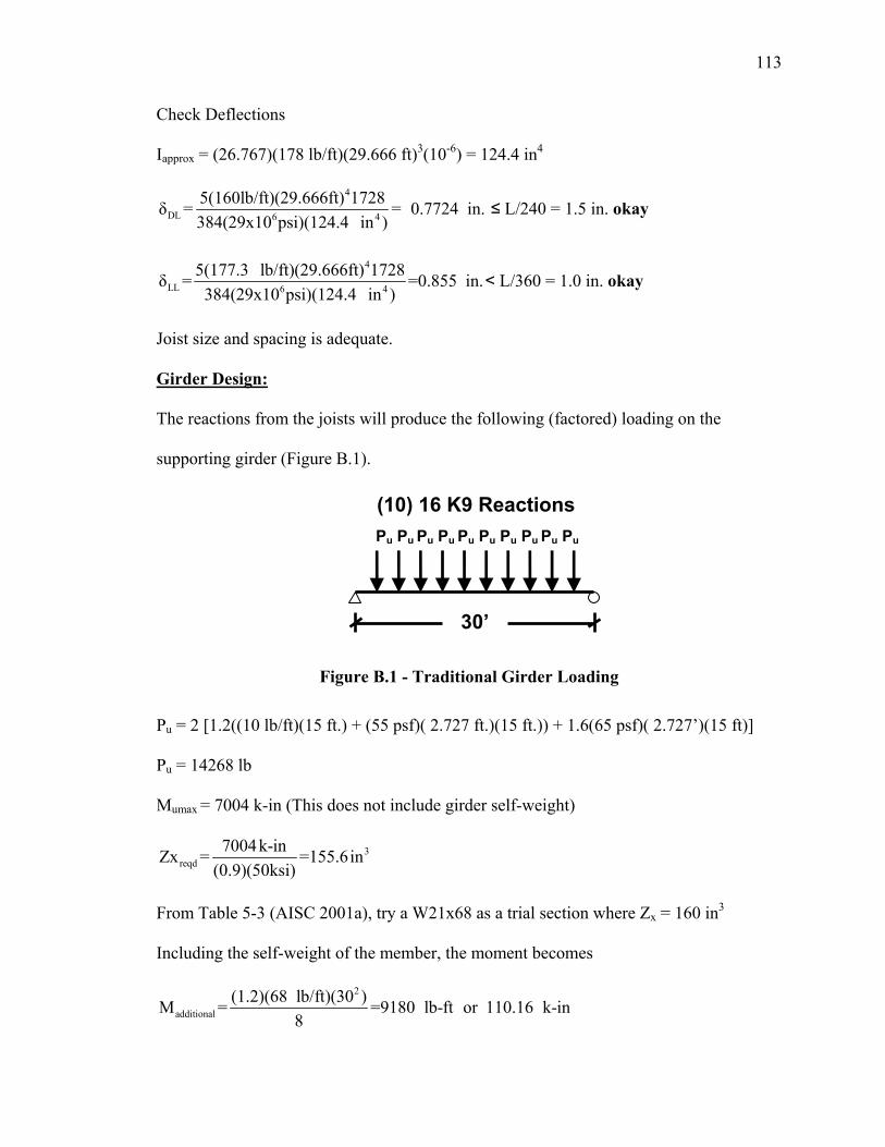
113
Check Deflections
Iapprox = (26.767)(178 lb/ft)(29.666 ft)3(10-6) = 124.4 in4
4
DL 6 4
5(160lb/ft)(29.666ft) 1728δ = = 0.7724 in.384(29x10 psi)(124.4 in )
≤ L/240 = 1.5 in. okay
4
LL 6 4
5(177.3 lb/ft)(29.666ft) 1728δ = =0.855 in.384(29x10 psi)(124.4 in )
< L/360 = 1.0 in. okay
Joist size and spacing is adequate.
Girder Design:
The reactions from the joists will produce the following (factored) loading on the
supporting girder (Figure B.1).
Figure B.1 - Traditional Girder Loading
Pu = 2 [1.2((10 lb/ft)(15 ft.) + (55 psf)( 2.727 ft.)(15 ft.)) + 1.6(65 psf)( 2.727’)(15 ft)]
Pu = 14268 lb
Mumax = 7004 k-in (This does not include girder self-weight)
3reqd
7004k-inZx = =155.6in(0.9)(50ksi)
From Table 5-3 (AISC 2001a), try a W21x68 as a trial section where Zx = 160 in3
Including the self-weight of the member, the moment becomes
2
additional(1.2)(68 lb/ft)(30 )M = =9180 lb-ft or 110.16 k-in
8
(10) 16 K9 Reactions
30’
Pu Pu Pu Pu Pu Pu Pu Pu Pu Pu
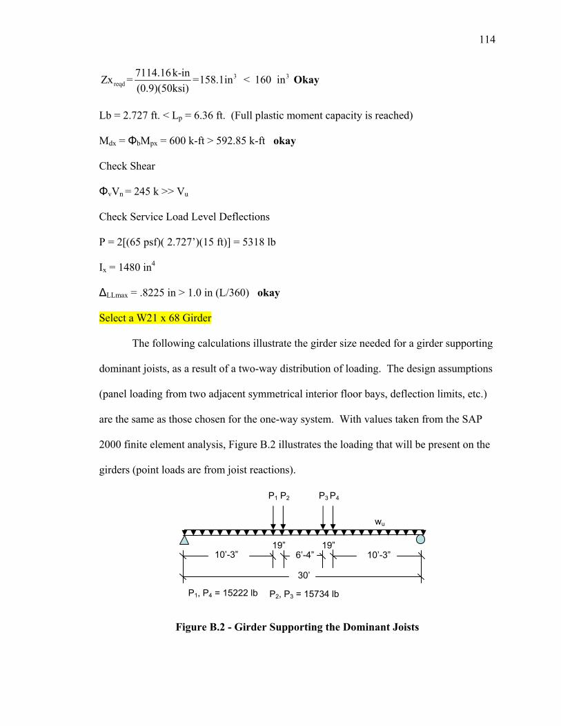
114
3 3reqd
7114.16k-inZx = =158.1in < 160 in(0.9)(50ksi)
Okay
Lb = 2.727 ft. < Lp = 6.36 ft. (Full plastic moment capacity is reached) Mdx = ΦbMpx = 600 k-ft > 592.85 k-ft okay
Check Shear
ΦvVn = 245 k >> Vu
Check Service Load Level Deflections
P = 2[(65 psf)( 2.727’)(15 ft)] = 5318 lb
Ix = 1480 in4
ΔLLmax = .8225 in > 1.0 in (L/360) okay
Select a W21 x 68 Girder
The following calculations illustrate the girder size needed for a girder supporting
dominant joists, as a result of a two-way distribution of loading. The design assumptions
(panel loading from two adjacent symmetrical interior floor bays, deflection limits, etc.)
are the same as those chosen for the one-way system. With values taken from the SAP
2000 finite element analysis, Figure B.2 illustrates the loading that will be present on the
girders (point loads are from joist reactions).
Figure B.2 - Girder Supporting the Dominant Joists
19”
30’
10’-3”
wu
P1 P2 P3 P4
P1, P4 = 15222 lb P2, P3 = 15734 lb
6’-4” 10’-3”19”
115
The girder shown in Figure B.2 will also support a uniform loading directly from the slab
equivalent to
wu = 1.2(55 psf)(6 ft.) + 1.6(65 psf)(6 ft.) = 1020 lb/ft
Girder Member Sizing
From the loading in Figure B.2
Mumax = 5483 k-in (girder self-weight not included)
3reqd
5483 k-inZx = =121.8 in(0.9)(50ksi)
From Table 5-3 in the steel manual (AISC 2001a), try a W18x60 as a trial section where
Zx = 123 in3. The girder is braced by the floor slab and joists; therefore, it will reach its
full plastic moment capacity. Including the self-wt of the member, additional uniform
loading becomes
1.2(65 k/ft) = 72 lb/ft
This results in a maximum moment of
Mu = 465 k-ft
because
Mdx = ΦbMpx = 461 k-ft ≈ 465 k-ft
the moment strength is deemed adequate.
Check Shear
ΦvVn = 204 k >> Vu
Check Service Load Level Deflections
Live load loading becomes
wserv = (65 psf)(6 ft.) = 390 lb/ft
P1 = P4 = 5628 lb and P2 = P3 = 5812 lb
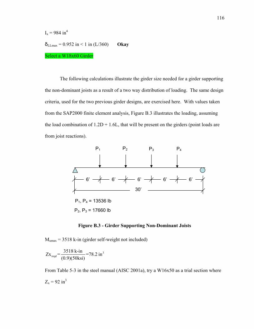
116
Ix = 984 in4
δLLmax = 0.952 in < 1 in (L/360) Okay
Select a W18x60 Girder
The following calculations illustrate the girder size needed for a girder supporting
the non-dominant joists as a result of a two way distribution of loading. The same design
criteria, used for the two previous girder designs, are exercised here. With values taken
from the SAP2000 finite element analysis, Figure B.3 illustrates the loading, assuming
the load combination of 1.2D + 1.6L, that will be present on the girders (point loads are
from joist reactions).
Figure B.3 - Girder Supporting Non-Dominant Joists
Mumax = 3518 k-in (girder self-weight not included)
3reqd
3518 k-inZx = =78.2 in(0.9)(50ksi)
From Table 5-3 in the steel manual (AISC 2001a), try a W16x50 as a trial section where
Zx = 92 in3
P1, P4 = 13536 lb
P2, P3 = 17660 lb
30’
P1 P2 P3 P4
6’ 6’ 6’ 6’ 6’
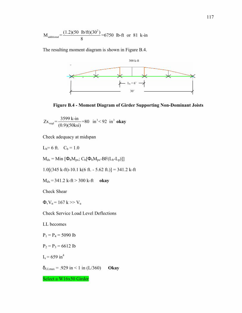
117
2
additional(1.2)(50 lb/ft)(30 )M = =6750 lb-ft or 81 k-in
8
The resulting moment diagram is shown in Figure B.4.
Figure B.4 - Moment Diagram of Girder Supporting Non-Dominant Joists
3 3reqd
3599 k-inZx = =80 in < 92 in(0.9)(50ksi)
okay
Check adequacy at midspan
Lb= 6 ft. Cb = 1.0
Mdx = Min [ΦbMpx; Cb[ΦbMpx-BF(Lb-Lp)]]
1.0[(345 k-ft)-10.1 k(6 ft. - 5.62 ft.)] = 341.2 k-ft
Mdx = 341.2 k-ft > 300 k-ft okay
Check Shear
ΦvVn = 167 k >> Vu
Check Service Load Level Deflections
LL becomes
P1 = P4 = 5090 lb
P2 = P3 = 6612 lb
Ix = 659 in4
δLLmax = .929 in < 1 in (L/360) Okay
Select a W16x50 Girder
Lb = 6’
30’
300 k-ft
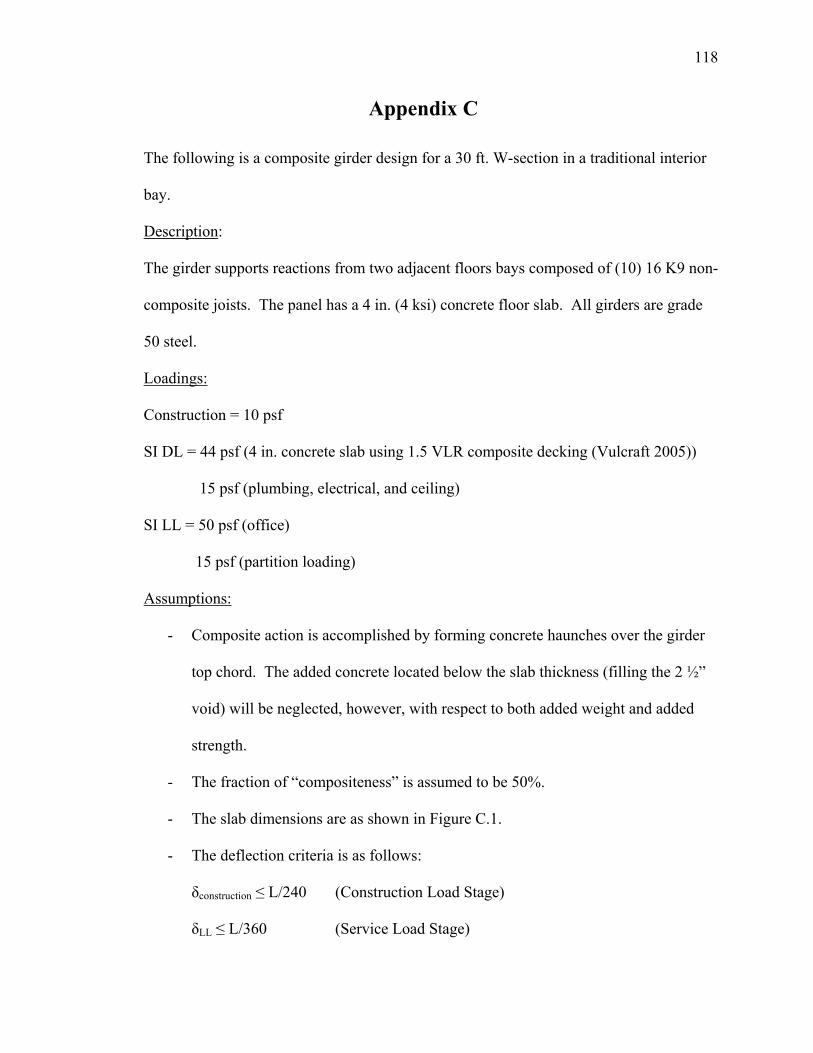
118
Appendix C
The following is a composite girder design for a 30 ft. W-section in a traditional interior
bay.
Description:
The girder supports reactions from two adjacent floors bays composed of (10) 16 K9 non-
composite joists. The panel has a 4 in. (4 ksi) concrete floor slab. All girders are grade
50 steel.
Loadings:
Construction = 10 psf
SI DL = 44 psf (4 in. concrete slab using 1.5 VLR composite decking (Vulcraft 2005))
15 psf (plumbing, electrical, and ceiling)
SI LL = 50 psf (office)
15 psf (partition loading)
Assumptions:
- Composite action is accomplished by forming concrete haunches over the girder
top chord. The added concrete located below the slab thickness (filling the 2 ½”
void) will be neglected, however, with respect to both added weight and added
strength.
- The fraction of “compositeness” is assumed to be 50%.
- The slab dimensions are as shown in Figure C.1.
- The deflection criteria is as follows:
δconstruction ≤ L/240 (Construction Load Stage)
δLL ≤ L/360 (Service Load Stage)
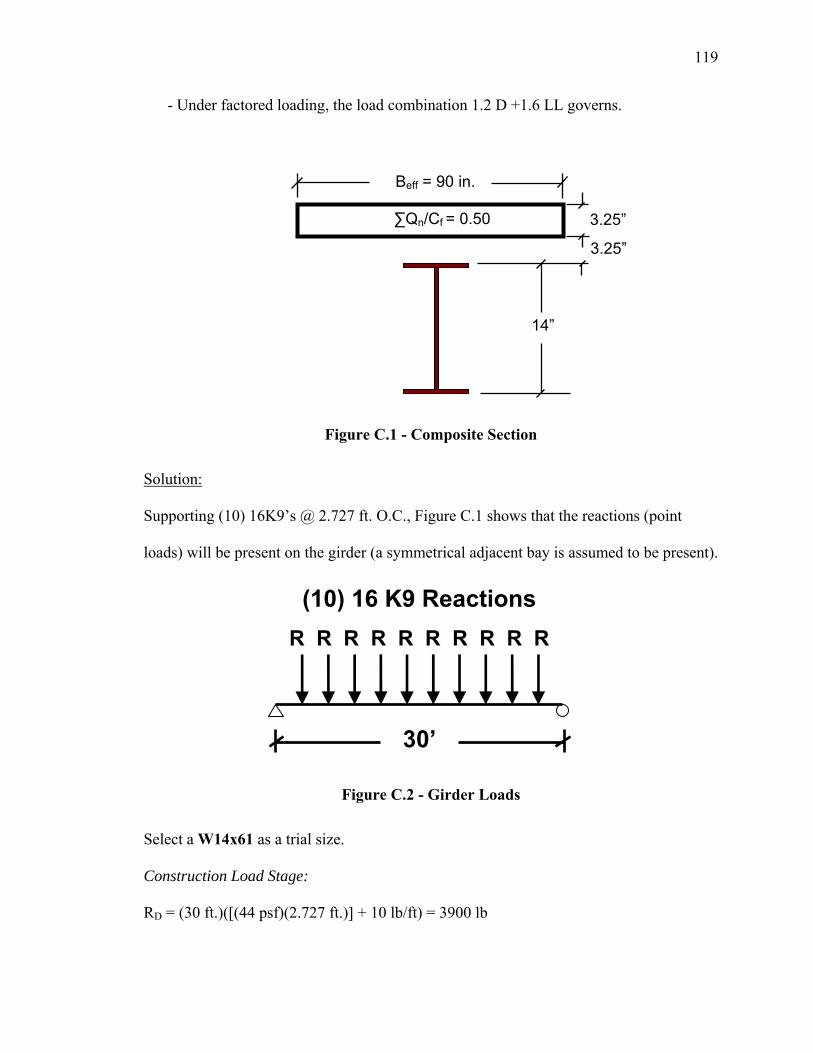
119
- Under factored loading, the load combination 1.2 D +1.6 LL governs.
Figure C.1 - Composite Section
Solution:
Supporting (10) 16K9’s @ 2.727 ft. O.C., Figure C.1 shows that the reactions (point
loads) will be present on the girder (a symmetrical adjacent bay is assumed to be present).
Figure C.2 - Girder Loads
Select a W14x61 as a trial size.
Construction Load Stage:
RD = (30 ft.)([(44 psf)(2.727 ft.)] + 10 lb/ft) = 3900 lb
Beff = 90 in.
14”
3.25”
3.25”
∑Qn/Cf = 0.50
(10) 16 K9 Reactions
30’
R R R R R R R R R R
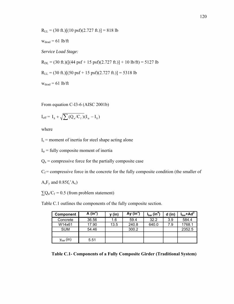
120
RLL = (30 ft.)[(10 psf)(2.727 ft.)] = 818 lb
wdead = 61 lb/ft
Service Load Stage:
RDL = (30 ft.)([(44 psf + 15 psf)(2.727 ft.)] + 10 lb/ft) = 5127 lb
RLL = (30 ft.)[(50 psf + 15 psf)(2.727 ft.)] = 5318 lb
wdead = 61 lb/ft
From equation C-I3-6 (AISC 2001b)
Ieff = )I(I)/C(QI StrfnS −+ ∑
where
Is = moment of inertia for steel shape acting alone
Itr = fully composite moment of inertia
Qn = compressive force for the partially composite case
Cf = compressive force in the concrete for the fully composite condition (the smaller of
AsFy and 0.85fc’Ac)
∑Qn/Cf = 0.5 (from problem statement)
Table C.1 outlines the components of the fully composite section.
Component A (in2) y (in) Ay (in3) Ibar (in4) d (in) Ibar+Ad2
Concrete 36.56 1.6 59.4 32.2 3.9 584.4W14x61 17.90 13.5 240.8 640.0 7.9 1768.1
SUM 54.46 300.2 2352.5
ybar (in) 5.51
Table C.1- Components of a Fully Composite Girder (Traditional System)
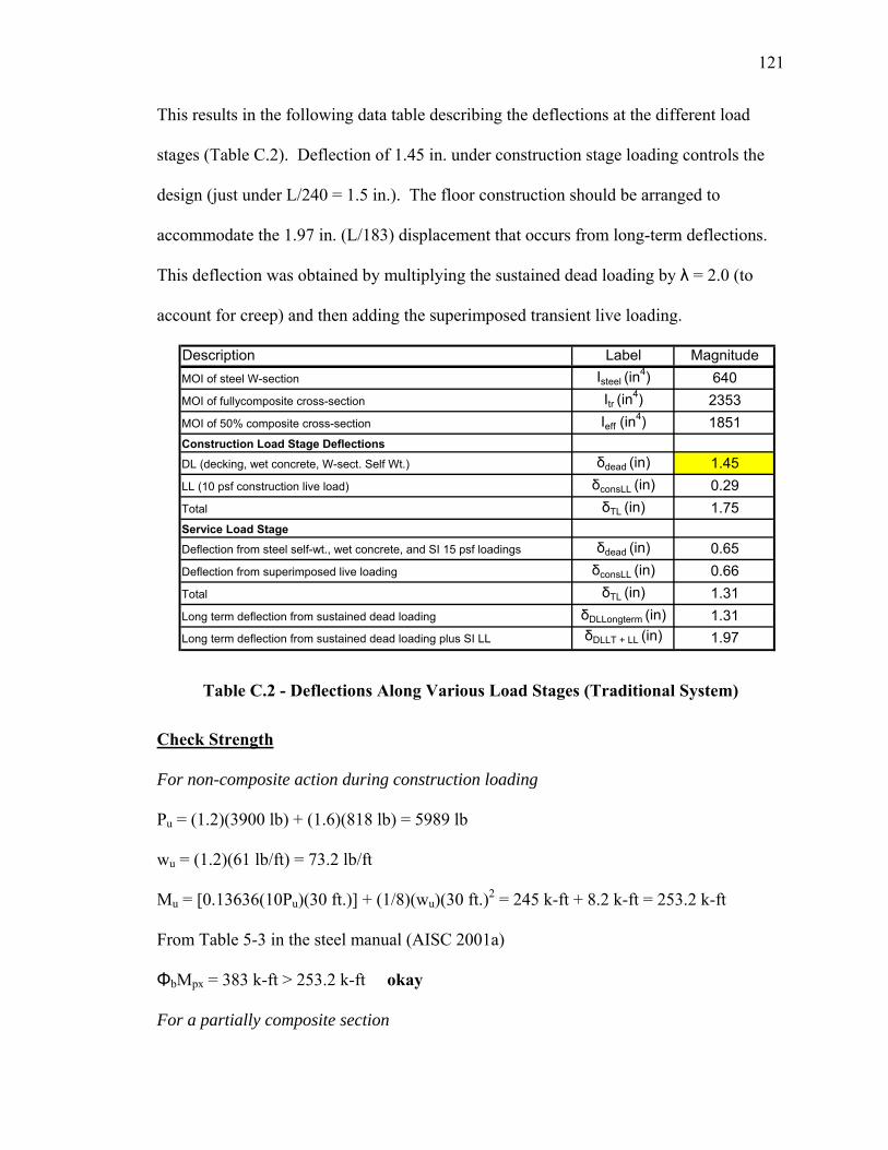
121
This results in the following data table describing the deflections at the different load
stages (Table C.2). Deflection of 1.45 in. under construction stage loading controls the
design (just under L/240 = 1.5 in.). The floor construction should be arranged to
accommodate the 1.97 in. (L/183) displacement that occurs from long-term deflections.
This deflection was obtained by multiplying the sustained dead loading by λ = 2.0 (to
account for creep) and then adding the superimposed transient live loading.
Description Label MagnitudeMOI of steel W-section Isteel (in
4) 640MOI of fullycomposite cross-section Itr (in
4) 2353MOI of 50% composite cross-section Ieff (in
4) 1851Construction Load Stage Deflections
DL (decking, wet concrete, W-sect. Self Wt.) δdead (in) 1.45LL (10 psf construction live load) δconsLL (in) 0.29Total δTL (in) 1.75Service Load Stage
Deflection from steel self-wt., wet concrete, and SI 15 psf loadings δdead (in) 0.65Deflection from superimposed live loading δconsLL (in) 0.66Total δTL (in) 1.31Long term deflection from sustained dead loading δDLLongterm (in) 1.31Long term deflection from sustained dead loading plus SI LL δDLLT + LL (in) 1.97
Table C.2 - Deflections Along Various Load Stages (Traditional System)
Check Strength
For non-composite action during construction loading
Pu = (1.2)(3900 lb) + (1.6)(818 lb) = 5989 lb
wu = (1.2)(61 lb/ft) = 73.2 lb/ft
Mu = [0.13636(10Pu)(30 ft.)] + (1/8)(wu)(30 ft.)2 = 245 k-ft + 8.2 k-ft = 253.2 k-ft
From Table 5-3 in the steel manual (AISC 2001a)
ΦbMpx = 383 k-ft > 253.2 k-ft okay
For a partially composite section
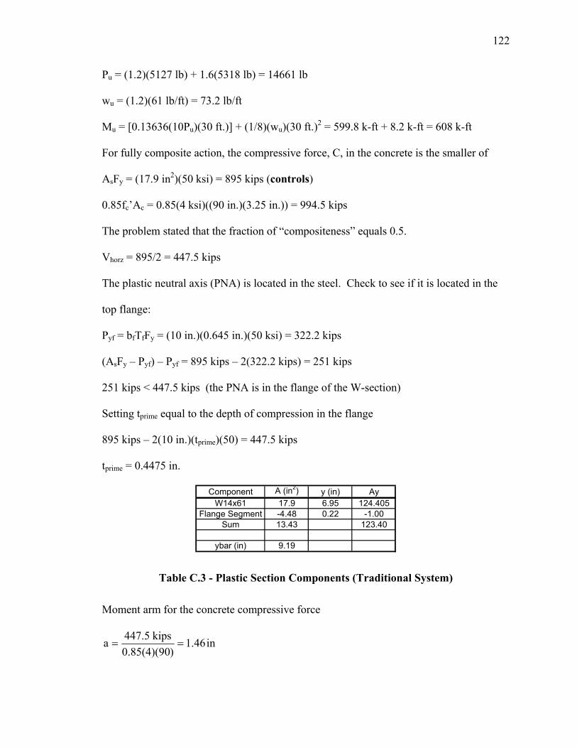
122
Pu = (1.2)(5127 lb) + 1.6(5318 lb) = 14661 lb
wu = (1.2)(61 lb/ft) = 73.2 lb/ft
Mu = [0.13636(10Pu)(30 ft.)] + (1/8)(wu)(30 ft.)2 = 599.8 k-ft + 8.2 k-ft = 608 k-ft
For fully composite action, the compressive force, C, in the concrete is the smaller of
AsFy = (17.9 in2)(50 ksi) = 895 kips (controls)
0.85fc’Ac = 0.85(4 ksi)((90 in.)(3.25 in.)) = 994.5 kips
The problem stated that the fraction of “compositeness” equals 0.5.
Vhorz = 895/2 = 447.5 kips
The plastic neutral axis (PNA) is located in the steel. Check to see if it is located in the
top flange:
Pyf = bfTfFy = (10 in.)(0.645 in.)(50 ksi) = 322.2 kips
(AsFy – Pyf) – Pyf = 895 kips – 2(322.2 kips) = 251 kips
251 kips < 447.5 kips (the PNA is in the flange of the W-section)
Setting tprime equal to the depth of compression in the flange
895 kips – 2(10 in.)(tprime)(50) = 447.5 kips
tprime = 0.4475 in.
Component A (in2) y (in) AyW14x61 17.9 6.95 124.405
Flange Segment -4.48 0.22 -1.00Sum 13.43 123.40
ybar (in) 9.19
Table C.3 - Plastic Section Components (Traditional System)
Moment arm for the concrete compressive force
in1.46)0.85(4)(90
kips447.5a ==
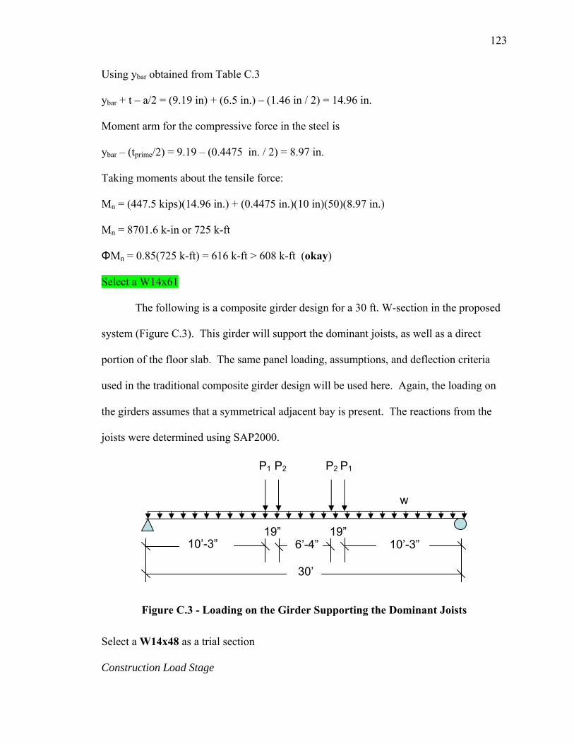
123
Using ybar obtained from Table C.3
ybar + t – a/2 = (9.19 in) + (6.5 in.) – (1.46 in / 2) = 14.96 in.
Moment arm for the compressive force in the steel is
ybar – (tprime/2) = 9.19 – (0.4475 in. / 2) = 8.97 in.
Taking moments about the tensile force:
Mn = (447.5 kips)(14.96 in.) + (0.4475 in.)(10 in)(50)(8.97 in.)
Mn = 8701.6 k-in or 725 k-ft
ΦMn = 0.85(725 k-ft) = 616 k-ft > 608 k-ft (okay)
Select a W14x61
The following is a composite girder design for a 30 ft. W-section in the proposed
system (Figure C.3). This girder will support the dominant joists, as well as a direct
portion of the floor slab. The same panel loading, assumptions, and deflection criteria
used in the traditional composite girder design will be used here. Again, the loading on
the girders assumes that a symmetrical adjacent bay is present. The reactions from the
joists were determined using SAP2000.
Figure C.3 - Loading on the Girder Supporting the Dominant Joists
Select a W14x48 as a trial section
Construction Load Stage
19”
30’
10’-3”
w
P1 P2 P2 P1
6’-4” 10’-3” 19”
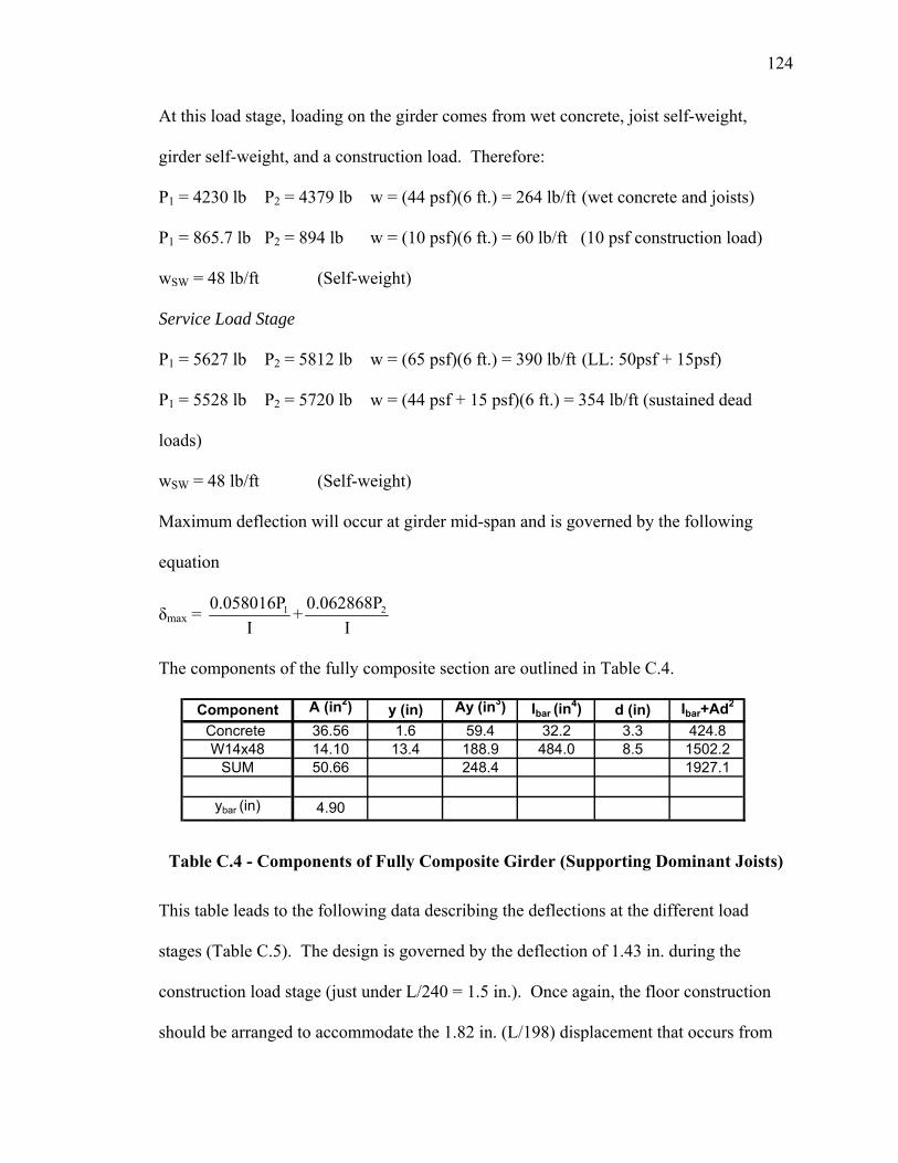
124
At this load stage, loading on the girder comes from wet concrete, joist self-weight,
girder self-weight, and a construction load. Therefore:
P1 = 4230 lb P2 = 4379 lb w = (44 psf)(6 ft.) = 264 lb/ft (wet concrete and joists)
P1 = 865.7 lb P2 = 894 lb w = (10 psf)(6 ft.) = 60 lb/ft (10 psf construction load)
wSW = 48 lb/ft (Self-weight)
Service Load Stage
P1 = 5627 lb P2 = 5812 lb w = (65 psf)(6 ft.) = 390 lb/ft (LL: 50psf + 15psf)
P1 = 5528 lb P2 = 5720 lb w = (44 psf + 15 psf)(6 ft.) = 354 lb/ft (sustained dead
loads)
wSW = 48 lb/ft (Self-weight)
Maximum deflection will occur at girder mid-span and is governed by the following
equation
δmax = 1 20.058016P 0.062868P+I I
The components of the fully composite section are outlined in Table C.4.
Component A (in2) y (in) Ay (in3) Ibar (in4) d (in) Ibar+Ad2
Concrete 36.56 1.6 59.4 32.2 3.3 424.8W14x48 14.10 13.4 188.9 484.0 8.5 1502.2
SUM 50.66 248.4 1927.1
ybar (in) 4.90
Table C.4 - Components of Fully Composite Girder (Supporting Dominant Joists)
This table leads to the following data describing the deflections at the different load
stages (Table C.5). The design is governed by the deflection of 1.43 in. during the
construction load stage (just under L/240 = 1.5 in.). Once again, the floor construction
should be arranged to accommodate the 1.82 in. (L/198) displacement that occurs from
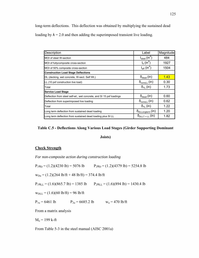
125
long-term deflections. This deflection was obtained by multiplying the sustained dead
loading by λ = 2.0 and then adding the superimposed transient live loading.
Description Label MagnitudeMOI of steel W-section Isteel (in
4) 484MOI of fullycomposite cross-section Itr (in
4) 1927MOI of 50% composite cross-section Ieff (in
4) 1504Construction Load Stage Deflections
DL (decking, wet concrete, W-sect. Self Wt.) δdead (in) 1.43LL (10 psf construction live load) δconsLL (in) 0.30Total δTL (in) 1.73Service Load Stage
Deflection from steel self-wt., wet concrete, and SI 15 psf loadings δdead (in) 0.60Deflection from superimposed live loading δconsLL (in) 0.62Total δTL (in) 1.22Long term deflection from sustained dead loading δDLLongterm (in) 1.20Long term deflection from sustained dead loading plus SI LL δDLLT + LL (in) 1.82
Table C.5 - Deflections Along Various Load Stages (Girder Supporting Dominant
Joists)
Check Strength
For non-composite action during construction loading
P1uD = (1.2)(4230 lb) = 5076 lb P2uD = (1.2)(4379 lb) = 5254.8 lb
wDu = (1.2)(264 lb/ft + 48 lb/ft) = 374.4 lb/ft
P1uLL = (1.6)(865.7 lb) = 1385 lb P2uLL = (1.6)(894 lb) = 1430.4 lb
wDLL = (1.6)(60 lb/ft) = 96 lb/ft
P1u = 6461 lb P2u = 6685.2 lb wu = 470 lb/ft
From a matrix analysis
Mu = 199 k-ft
From Table 5-3 in the steel manual (AISC 2001a)
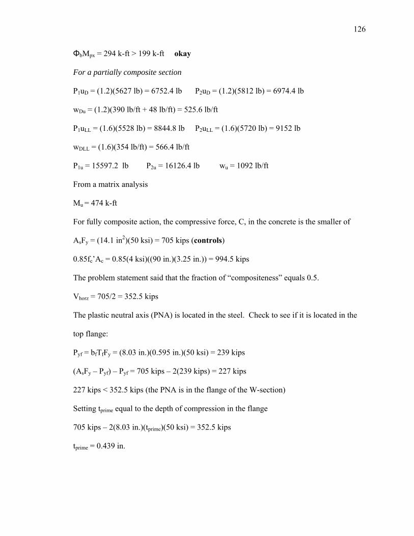
126
ΦbMpx = 294 k-ft > 199 k-ft okay
For a partially composite section
P1uD = (1.2)(5627 lb) = 6752.4 lb P2uD = (1.2)(5812 lb) = 6974.4 lb
wDu = (1.2)(390 lb/ft + 48 lb/ft) = 525.6 lb/ft
P1uLL = (1.6)(5528 lb) = 8844.8 lb P2uLL = (1.6)(5720 lb) = 9152 lb
wDLL = (1.6)(354 lb/ft) = 566.4 lb/ft
P1u = 15597.2 lb P2u = 16126.4 lb wu = 1092 lb/ft
From a matrix analysis
Mu = 474 k-ft
For fully composite action, the compressive force, C, in the concrete is the smaller of
AsFy = (14.1 in2)(50 ksi) = 705 kips (controls)
0.85fc’Ac = 0.85(4 ksi)((90 in.)(3.25 in.)) = 994.5 kips
The problem statement said that the fraction of “compositeness” equals 0.5.
Vhorz = 705/2 = 352.5 kips
The plastic neutral axis (PNA) is located in the steel. Check to see if it is located in the
top flange:
Pyf = bfTfFy = (8.03 in.)(0.595 in.)(50 ksi) = 239 kips
(AsFy – Pyf) – Pyf = 705 kips – 2(239 kips) = 227 kips
227 kips < 352.5 kips (the PNA is in the flange of the W-section)
Setting tprime equal to the depth of compression in the flange
705 kips – 2(8.03 in.)(tprime)(50 ksi) = 352.5 kips
tprime = 0.439 in.
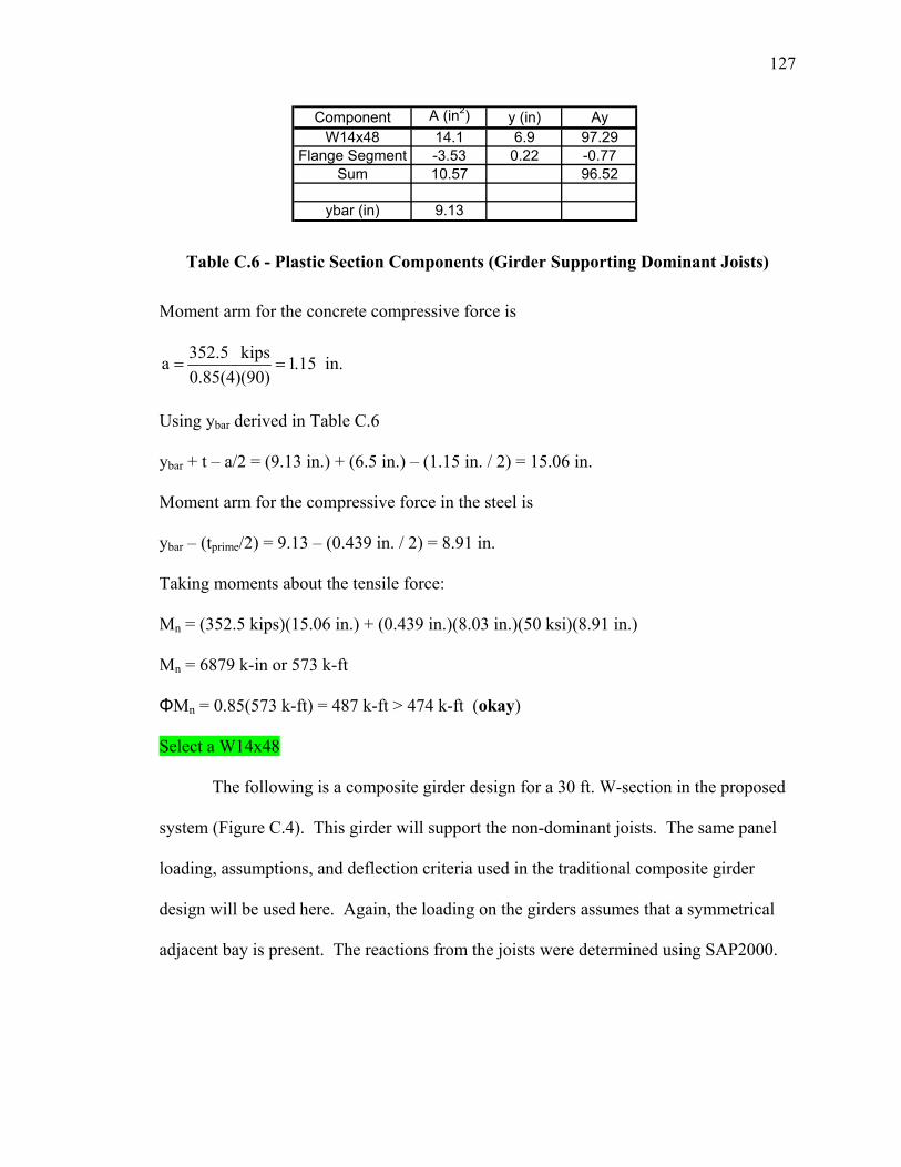
127
Component A (in2) y (in) AyW14x48 14.1 6.9 97.29
Flange Segment -3.53 0.22 -0.77Sum 10.57 96.52
ybar (in) 9.13
Table C.6 - Plastic Section Components (Girder Supporting Dominant Joists)
Moment arm for the concrete compressive force is
352.5 kipsa 1.15 in.0.85(4)(90)
= =
Using ybar derived in Table C.6
ybar + t – a/2 = (9.13 in.) + (6.5 in.) – (1.15 in. / 2) = 15.06 in.
Moment arm for the compressive force in the steel is
ybar – (tprime/2) = 9.13 – (0.439 in. / 2) = 8.91 in.
Taking moments about the tensile force:
Mn = (352.5 kips)(15.06 in.) + (0.439 in.)(8.03 in.)(50 ksi)(8.91 in.)
Mn = 6879 k-in or 573 k-ft
ΦMn = 0.85(573 k-ft) = 487 k-ft > 474 k-ft (okay)
Select a W14x48
The following is a composite girder design for a 30 ft. W-section in the proposed
system (Figure C.4). This girder will support the non-dominant joists. The same panel
loading, assumptions, and deflection criteria used in the traditional composite girder
design will be used here. Again, the loading on the girders assumes that a symmetrical
adjacent bay is present. The reactions from the joists were determined using SAP2000.
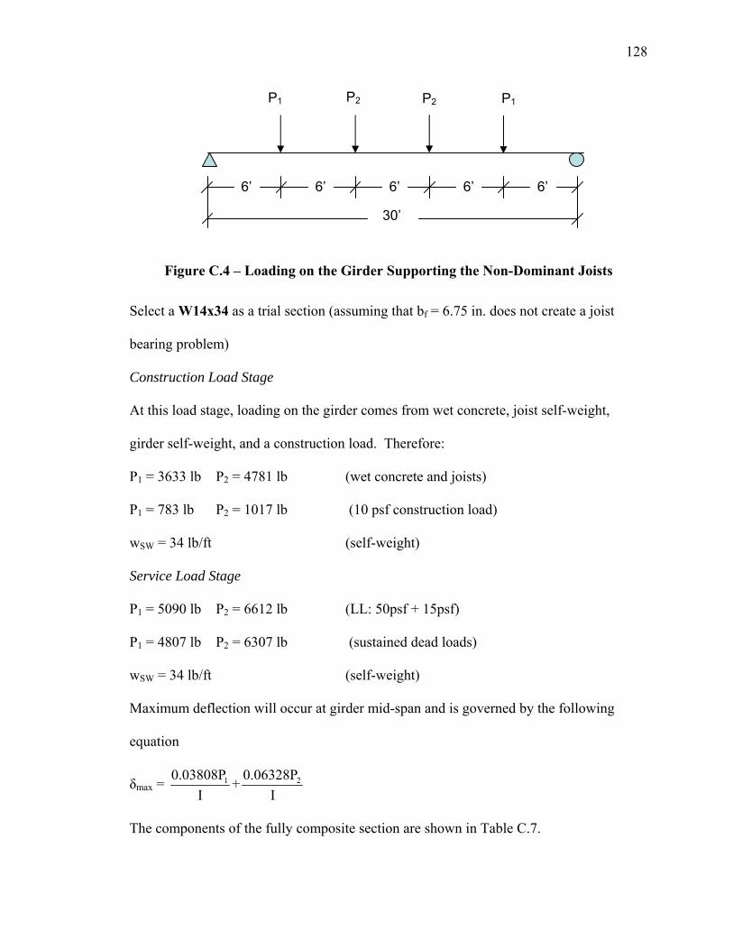
128
Figure C.4 – Loading on the Girder Supporting the Non-Dominant Joists
Select a W14x34 as a trial section (assuming that bf = 6.75 in. does not create a joist
bearing problem)
Construction Load Stage
At this load stage, loading on the girder comes from wet concrete, joist self-weight,
girder self-weight, and a construction load. Therefore:
P1 = 3633 lb P2 = 4781 lb (wet concrete and joists)
P1 = 783 lb P2 = 1017 lb (10 psf construction load)
wSW = 34 lb/ft (self-weight)
Service Load Stage
P1 = 5090 lb P2 = 6612 lb (LL: 50psf + 15psf)
P1 = 4807 lb P2 = 6307 lb (sustained dead loads)
wSW = 34 lb/ft (self-weight)
Maximum deflection will occur at girder mid-span and is governed by the following
equation
δmax = 1 20.03808P 0.06328P+I I
The components of the fully composite section are shown in Table C.7.
30’
P1 P2 P2 P1
6’ 6’ 6’ 6’ 6’
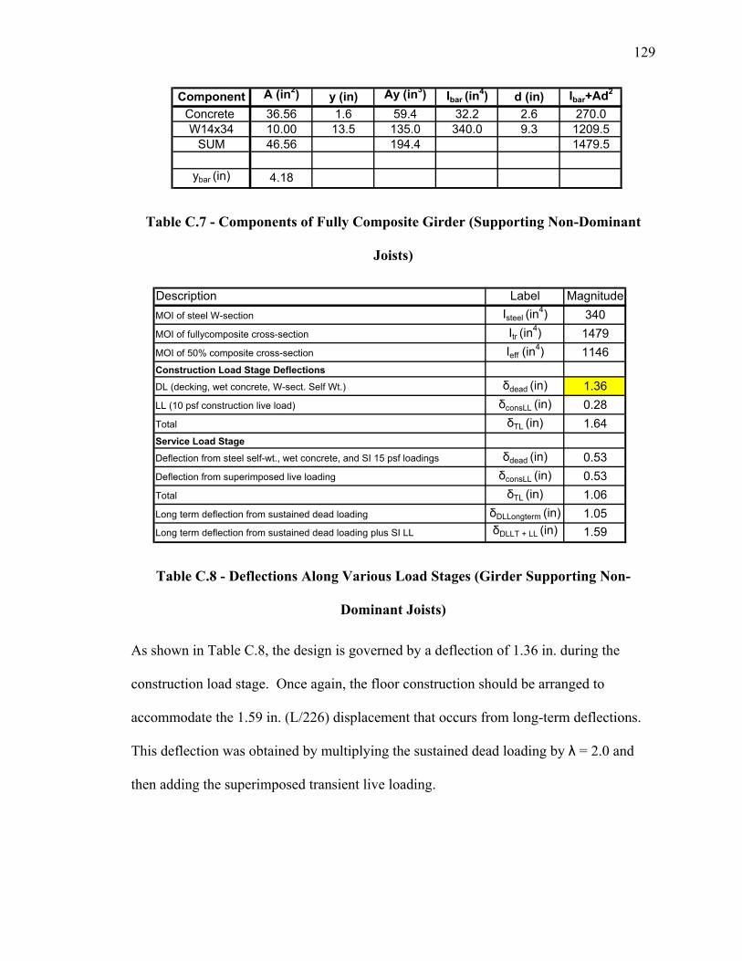
129
Component A (in2) y (in) Ay (in3) Ibar (in4) d (in) Ibar+Ad2
Concrete 36.56 1.6 59.4 32.2 2.6 270.0W14x34 10.00 13.5 135.0 340.0 9.3 1209.5
SUM 46.56 194.4 1479.5
ybar (in) 4.18
Table C.7 - Components of Fully Composite Girder (Supporting Non-Dominant
Joists)
Description Label MagnitudeMOI of steel W-section Isteel (in
4) 340MOI of fullycomposite cross-section Itr (in
4) 1479MOI of 50% composite cross-section Ieff (in
4) 1146Construction Load Stage Deflections
DL (decking, wet concrete, W-sect. Self Wt.) δdead (in) 1.36LL (10 psf construction live load) δconsLL (in) 0.28Total δTL (in) 1.64Service Load Stage
Deflection from steel self-wt., wet concrete, and SI 15 psf loadings δdead (in) 0.53Deflection from superimposed live loading δconsLL (in) 0.53Total δTL (in) 1.06Long term deflection from sustained dead loading δDLLongterm (in) 1.05Long term deflection from sustained dead loading plus SI LL δDLLT + LL (in) 1.59
Table C.8 - Deflections Along Various Load Stages (Girder Supporting Non-
Dominant Joists)
As shown in Table C.8, the design is governed by a deflection of 1.36 in. during the
construction load stage. Once again, the floor construction should be arranged to
accommodate the 1.59 in. (L/226) displacement that occurs from long-term deflections.
This deflection was obtained by multiplying the sustained dead loading by λ = 2.0 and
then adding the superimposed transient live loading.

130
Check Strength
For non-composite action during construction loading
P1uD = (1.2)(3633 lb) = 4360 lb P2uD = (1.2)(4781 lb) = 5737 lb
wDu = (1.2)(34 lb/ft) = 40.8 lb/ft
P1625eun825uLL = (1.6)(783 lb) = 1253 lb P2uLL = (1.6)(1017 lb) = 1627 lb
P1u = 5613 lb P2u = 7364 lb wu = 40.8 lb/ft
From a matrix analysis
Mu = 127 k-ft
From (AISC 2001a) table 5-3
ΦbMpx = 203 k-ft > 127 k-ft okay
For a partially composite section
P1uD = (1.2)(4807 lb) = 5769 lb P2uD = (1.2)(6307 lb) = 7568 lb
wDu = (1.2)(34 lb/ft) = 40.8 lb/ft
P1uLL = (1.6)(5090 lb) = 8144 lb P2uLL = (1.6)(6612 lb) = 10580 lb
P1u = 13913 lb P2u = 18148 lb wu = 40.8 lb/ft
From a matrix analysis
Mu = 306 k-ft
For fully composite action, the compressive force, C, in the concrete is the smaller of
AsFy = (10.0 in2)(50 ksi) = 500 kips (controls)
0.85fc’Ac = 0.85(4 ksi)((90 in.)(3.25 in.)) = 994.5 kips
The problem stated that the fraction of “compositeness” equals 0.5.
Vhorz = 500/2 = 250 kips
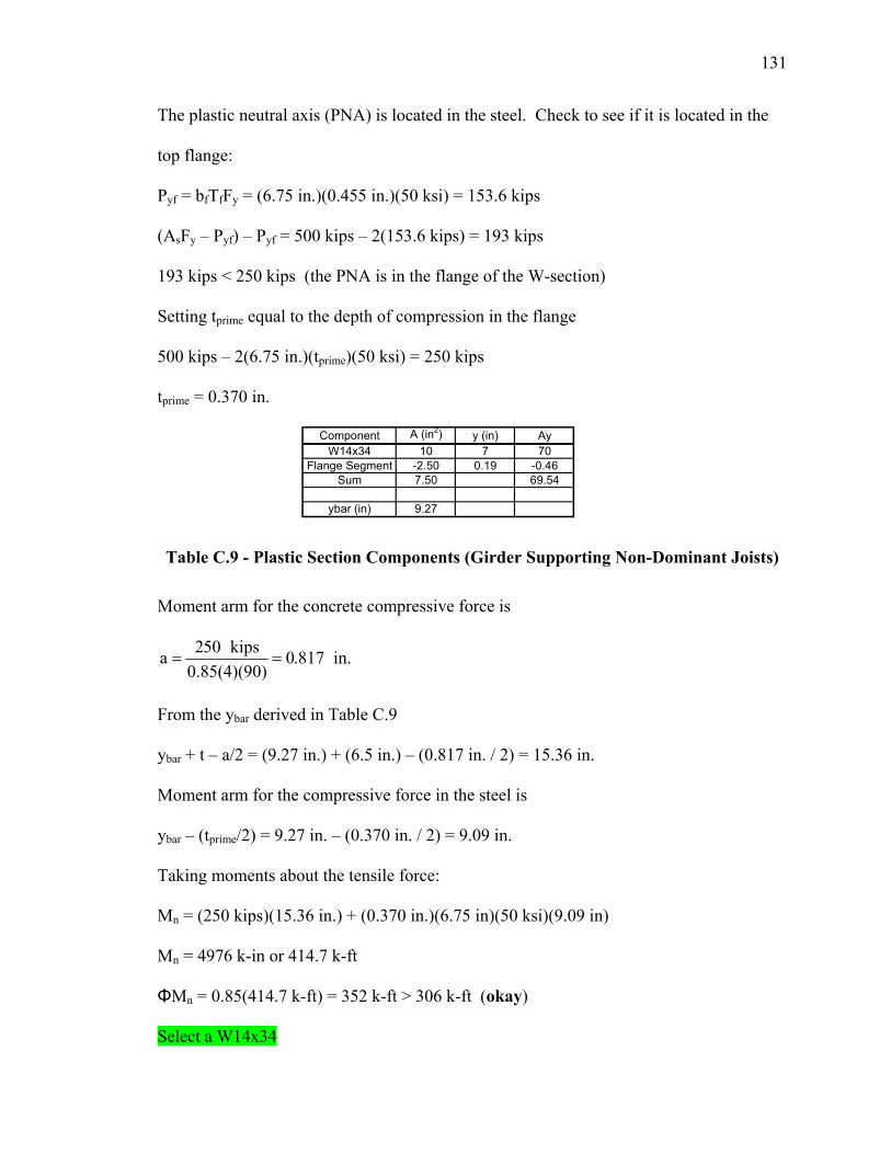
131
The plastic neutral axis (PNA) is located in the steel. Check to see if it is located in the
top flange:
Pyf = bfTfFy = (6.75 in.)(0.455 in.)(50 ksi) = 153.6 kips
(AsFy – Pyf) – Pyf = 500 kips – 2(153.6 kips) = 193 kips
193 kips < 250 kips (the PNA is in the flange of the W-section)
Setting tprime equal to the depth of compression in the flange
500 kips – 2(6.75 in.)(tprime)(50 ksi) = 250 kips
tprime = 0.370 in.
Component A (in2) y (in) AyW14x34 10 7 70
Flange Segment -2.50 0.19 -0.46Sum 7.50 69.54
ybar (in) 9.27
Table C.9 - Plastic Section Components (Girder Supporting Non-Dominant Joists)
Moment arm for the concrete compressive force is
250 kipsa 0.817 in.0.85(4)(90)
= =
From the ybar derived in Table C.9
ybar + t – a/2 = (9.27 in.) + (6.5 in.) – (0.817 in. / 2) = 15.36 in.
Moment arm for the compressive force in the steel is
ybar – (tprime/2) = 9.27 in. – (0.370 in. / 2) = 9.09 in.
Taking moments about the tensile force:
Mn = (250 kips)(15.36 in.) + (0.370 in.)(6.75 in)(50 ksi)(9.09 in)
Mn = 4976 k-in or 414.7 k-ft
ΦMn = 0.85(414.7 k-ft) = 352 k-ft > 306 k-ft (okay)
Select a W14x34