twopage monochrome monitor
DESCRIPTION
Apple Service Manual for the Two Page Monochrome MonitorTRANSCRIPT
Service Source
K
Apple Two-Page MonoMonitor
Service Source
K
Basics
Two-Page Monochrome Monitor
Basics Monitor Distortion - 1
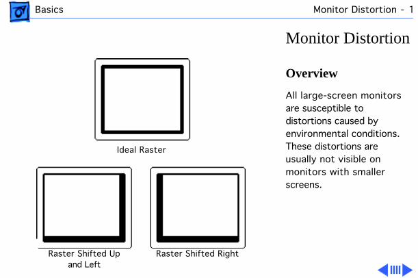
Monitor Distortion
Overview
All large-screen monitors are susceptible to distortions caused by environmental conditions. These distortions are usually not visible on monitors with smaller screens.
Ideal Raster
Raster Shifted Upand Left
Raster Shifted Right
Basics Monitor Distortion - 2
Important:
Even monitors set to factory specifications may appear distorted when set up in a new environment.
Common environmentally-caused distortions are shown on this and the following cards. Always check first for environmental causes before attempting to repair or adjust a monitor with a distorted raster.
Basics Monitor Distortion - 3
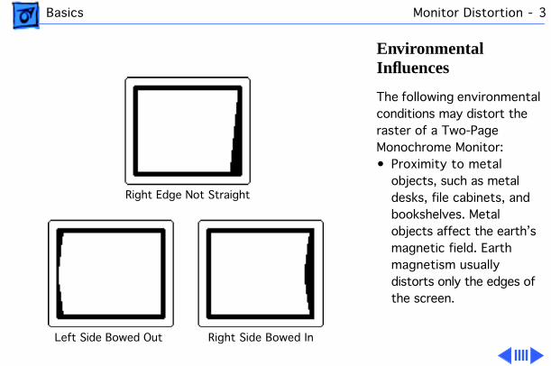
Environmental Influences
The following environmental conditions may distort the raster of a Two-Page Monochrome Monitor:• Proximity to metal
objects, such as metal desks, file cabinets, and bookshelves. Metal objects affect the earth’s magnetic field. Earth magnetism usually distorts only the edges of the screen.
Right Edge Not Straight
Left Side Bowed Out Right Side Bowed In
Basics Monitor Distortion - 4
• Fluorescent lights, other monitors, or electronic appliances such as coffee makers and copy machines. These objects cause dynamic raster distortion, that is, movement or jitter of the image.
Basics Monitor Distortion - 5
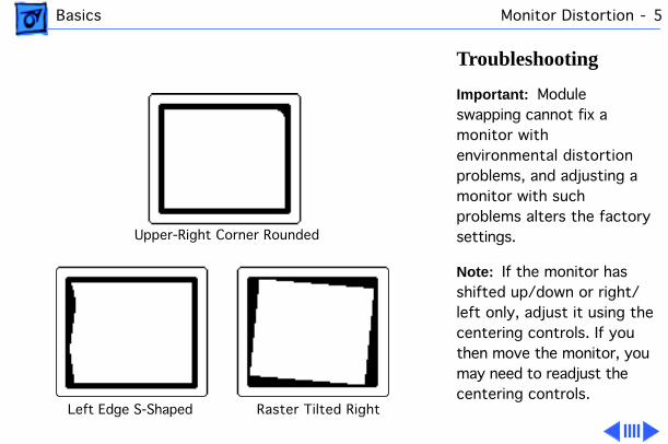
Troubleshooting
Important:
Module swapping cannot fix a monitor with environmental distortion problems, and adjusting a monitor with such problems alters the factory settings.
Note:
If the monitor has shifted up/down or right/left only, adjust it using the centering controls. If you then move the monitor, you may need to readjust the centering controls.
Upper-Right Corner Rounded
Left Edge S-Shaped Raster Tilted Right
Basics Monitor Distortion - 6
Before adjusting a monitor with a distorted raster, try the following:• Swivel or move the
monitor, or• Remove the monitor from
the building and recheck it in another location.
If the display changes (for better or worse) when you move it to another location, the environment is the source of the problem. Relocate the monitor or remove the distortion-causing object.
Basics Monitor Distortion - 7
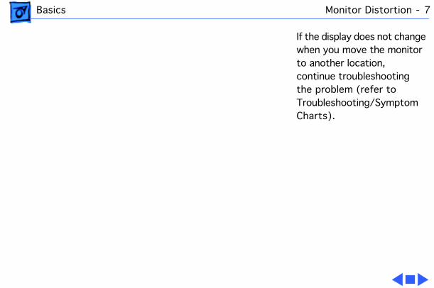
If the display does not change when you move the monitor to another location, continue troubleshooting the problem (refer to Troubleshooting/Symptom Charts).
Service Source
K
Specifications
Apple Two-Page MonochromeMonitor
Specifications Characteristics - 2
Characteristics
Picture Tube
21-in. diagonal screen (20-in. viewable image)Phosphor EIA Type P4 (white)Flat, square, high-contrast, antiglare surface
Screen Resolution
1,152 x 870 lines; 77 dpiDisplays up to 16 grays with 512K of video RAM
Scan Rates
Vertical refresh rate: 75 HzHorizontal scan rate: 68.7 kHzDot clock: 100 MHz
Specifications Characteristics - 3
Active Video Display Area
15 in. by 11.3 in.(381 mm by 287 mm)
Input Signal
Video: analog; RS–343 standard
Specifications Controls - 4
Controls
User Controls
Rear panel: power switchRight side: brightness and contrast controls
Specifications Physical and Electrical - 5
Physical and Electrical
Power Supply
Universal power supplyVoltage: 90–270 VAC, self-configuringFrequency: 47–63 HzPower: 95 W maximum
Size and Weight
Height: 15.7 in. (399 mm)—add 3.2 in. (81 mm) for integrated stand
Width: 19.5 in. (495 mm)Depth: 17.4 in. (442 mm)Weight: 55 lb. (25 kg)
Monitor Stand
Integrated, tilt-and-swivel stand
Specifications Operating Environment - 6
Operating Environment
Temperature
50°F–95°F (10°C–35°C)
Humidity
90% maximum, noncondensing
Altitude
10,000 ft. (3,048 m) maximum
Service Source
K
Troubleshooting
Apple Two-Page MonochromeMonitor
Troubleshooting General/ - 1
General
The Symptom Charts included in this chapter will help you diagnose specific symptoms related to your product. Because cures are listed on the charts in the order of most likely solution, try the first cure first. Verify whether or not the product continues to exhibit the symptom. If the symptom persists, try the next cure. (Note: If you have replaced a module, reinstall the original module before you proceed to the next cure.)
If you are not sure what the problem is, or if the Symptom Charts do not resolve the problem, refer to the Flowchart for the product family.
For additional assistance, contact Apple Technical Support.
Troubleshooting Symptom Charts/No Raster - 2
Symptom Charts
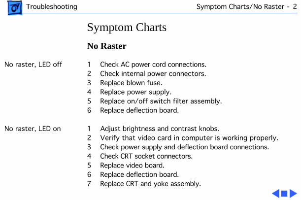
No Raster
No raster, LED off 1 Check AC power cord connections.2 Check internal power connectors.3 Replace blown fuse.4 Replace power supply.5 Replace on/off switch filter assembly.6 Replace deflection board.
No raster, LED on 1 Adjust brightness and contrast knobs.2 Verify that video card in computer is working properly.3 Check power supply and deflection board connections.4 Check CRT socket connectors.5 Replace video board.6 Replace deflection board.7 Replace CRT and yoke assembly.
Troubleshooting Symptom Charts/Geometry - 3
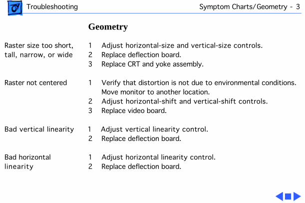
Geometry
Raster size too short, tall, narrow, or wide
1 Adjust horizontal-size and vertical-size controls.2 Replace deflection board.3 Replace CRT and yoke assembly.
Raster not centered 1 Verify that distortion is not due to environmental conditions. Move monitor to another location.
2 Adjust horizontal-shift and vertical-shift controls.3 Replace video board.
Bad vertical linearity 1 Adjust vertical linearity control.2 Replace deflection board.
Bad horizontal linearity
1 Adjust horizontal linearity control.2 Replace deflection board.
Troubleshooting Symptom Charts/Synchronization - 4
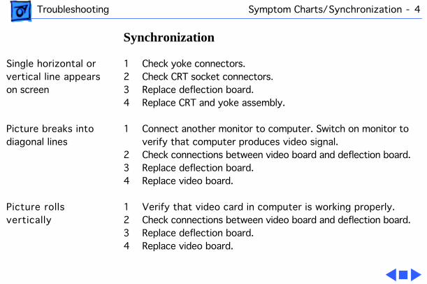
Synchronization
Single horizontal or vertical line appears on screen
1 Check yoke connectors.2 Check CRT socket connectors.3 Replace deflection board.4 Replace CRT and yoke assembly.
Picture breaks into diagonal lines
1 Connect another monitor to computer. Switch on monitor to verify that computer produces video signal.
2 Check connections between video board and deflection board.3 Replace deflection board.4 Replace video board.
Picture rolls vertically
1 Verify that video card in computer is working properly.2 Check connections between video board and deflection board.3 Replace deflection board.4 Replace video board.
Troubleshooting Symptom Charts/Video - 5
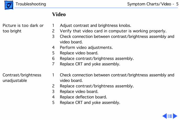
Video
Picture is too dark or too bright
1 Adjust contrast and brightness knobs.2 Verify that video card in computer is working properly.3 Check connection between contrast/brightness assembly and
video board.4 Perform video adjustments.5 Replace video board.6 Replace contrast/brightness assembly.7 Replace CRT and yoke assembly.
Contrast/brightness unadjustable
1 Check connection between contrast/brightness assembly and video board.
2 Replace contrast/brightness assembly.3 Replace video board.4 Replace deflection board.5 Replace CRT and yoke assembly.
Troubleshooting Symptom Charts/
(Continued)
- 6
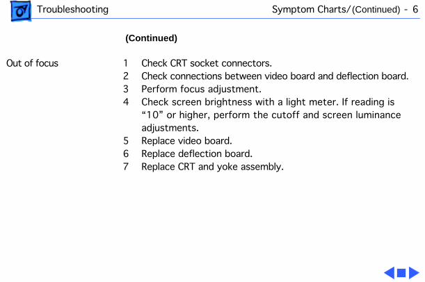
(Continued)
Out of focus 1 Check CRT socket connectors.2 Check connections between video board and deflection board.3 Perform focus adjustment.4 Check screen brightness with a light meter. If reading is
“10” or higher, perform the cutoff and screen luminance adjustments.
5 Replace video board.6 Replace deflection board.7 Replace CRT and yoke assembly.
Troubleshooting Symptom Charts/Miscellaneous - 7
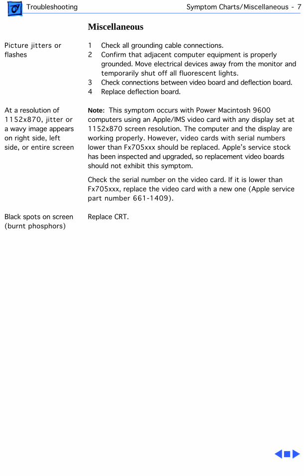
Miscellaneous
Picture jitters or flashes
1 Check all grounding cable connections.2 Confirm that adjacent computer equipment is properly
grounded. Move electrical devices away from the monitor and temporarily shut off all fluorescent lights.
3 Check connections between video board and deflection board.4 Replace deflection board.
At a resolution of 1152x870, jitter or a wavy image appears on right side, left side, or entire screen
Note:
This symptom occurs with Power Macintosh 9600 computers using an Apple/IMS video card with any display set at 1152x870 screen resolution. The computer and the display are working properly. However, video cards with serial numbers lower than Fx705xxx should be replaced. Apple’s service stock has been inspected and upgraded, so replacement video boards should not exhibit this symptom.
Check the serial number on the video card. If it is lower than Fx705xxx, replace the video card with a new one (Apple service part number 661-1409).
Black spots on screen (burnt phosphors)
Replace CRT.
Troubleshooting Symptom Charts/Monitor Stand - 8
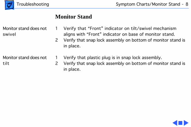
Monitor Stand
Monitor stand does not swivel
1 Verify that “Front” indicator on tilt/swivel mechanism aligns with “Front” indicator on base of monitor stand.
2 Verify that snap lock assembly on bottom of monitor stand is in place.
Monitor stand does not tilt
1 Verify that plastic plug is in snap lock assembly.2 Verify that snap lock assembly on bottom of monitor stand is
in place.
Service Source
K
Take Apart
Apple Two-Page MonochromeMonitor
Take Apart Swivel Stand - 1
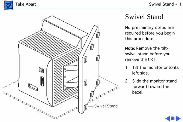
Swivel Stand
No preliminary steps are required before you begin this procedure.
Note:
Remove the tilt-swivel stand before you remove the CRT.
1 Tilt the monitor onto its left side.
2 Slide the monitor stand forward toward the bezel.
Swivel Stand
Take Apart Swivel Stand - 2
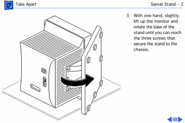
3 With one hand, slightly lift up the monitor and rotate the base of the stand until you can reach the three screws that secure the stand to the chassis.
Take Apart Swivel Stand - 3
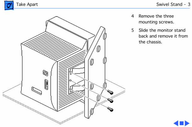
4 Remove the three mounting screws.
5 Slide the monitor stand back and remove it from the chassis.
Take Apart Rear Cover - 4
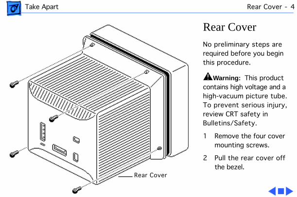
Rear Cover
No preliminary steps are required before you begin this procedure.
±
Warning:
This product contains high voltage and a high-vacuum picture tube. To prevent serious injury, review CRT safety in Bulletins/Safety.
1 Remove the four cover mounting screws.
2 Pull the rear cover off the bezel.
Rear Cover
Take Apart Access Cover - 5
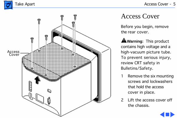
Access Cover
Before you begin, remove the rear cover.
±
Warning:
This product contains high voltage and a high-vacuum picture tube. To prevent serious injury, review CRT safety in Bulletins/Safety.
1 Remove the six mounting screws and lockwashers that hold the access cover in place.
2 Lift the access cover off the chassis.
AccessCover
Take Apart Video Board - 6
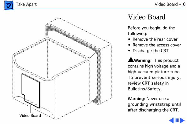
Video Board
Before you begin, do the following:• Remove the rear cover• Remove the access cover• Discharge the CRT
±
Warning:
This product contains high voltage and a high-vacuum picture tube. To prevent serious injury, review CRT safety in Bulletins/Safety.
Warning:
Never use a grounding wriststrap until after discharging the CRT.
Video Board
Take Apart Video Board - 7
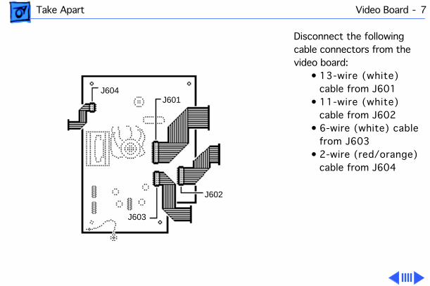
Disconnect the following cable connectors from the video board:
• 13-wire (white) cable from J601
• 11-wire (white) cable from J602
• 6-wire (white) cable from J603
• 2-wire (red/orange) cable from J604
J604
J603
J602
J601
Take Apart Video Board - 8
Caution:
Do not remove the connectors by pulling on the connector cables. If the connectors are difficult to disconnect, slip a jeweler’s screwdriver between the two halves of the connector and carefully pry the halves apart.
Take Apart Video Board - 9
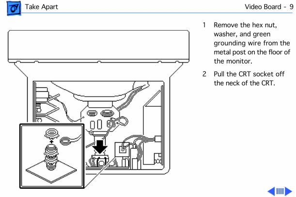
1 Remove the hex nut, washer, and green grounding wire from the metal post on the floor of the monitor.
2 Pull the CRT socket off the neck of the CRT.
Take Apart Video Board - 10
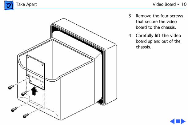
3 Remove the four screws that secure the video board to the chassis.
4 Carefully lift the video board up and out of the chassis.
Take Apart Deflection Board - 11
Deflection Board
Before you begin, do the following:• Remove the rear cover• Remove the access cover• Discharge the CRT• Remove the anode cap
±
Warning:
This product contains high voltage and a high-vacuum picture tube. To prevent serious injury, review CRT safety in Bulletins/Safety.
Take Apart Deflection Board - 12
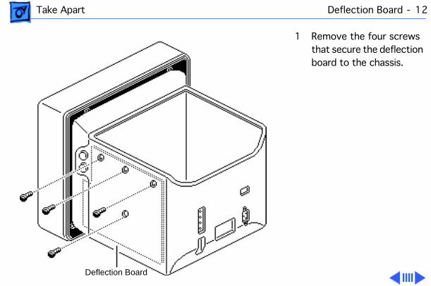
1 Remove the four screws that secure the deflection board to the chassis.
Deflection Board
Take Apart Deflection Board - 13
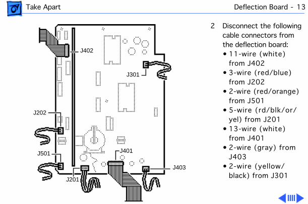
2 Disconnect the following cable connectors from the deflection board:• 11-wire (white)
from J402• 3-wire (red/blue)
from J202• 2-wire (red/orange)
from J501• 5-wire (rd/blk/or/
yel) from J201• 13-wire (white)
from J401• 2-wire (gray) from
J403• 2-wire (yellow/
black) from J301
J402
J301
J401
J202
J501
J201
J403
Take Apart Deflection Board - 14
Caution:
Do not remove the connectors by pulling on the connector cables. If the connectors are difficult to disconnect, slip a jeweler’s screwdriver between the two halves of the connector and carefully pry the halves apart.
Take Apart Deflection Board - 15
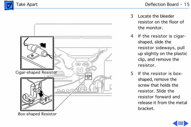
3 Locate the bleeder resistor on the floor of the monitor.
4 If the resistor is cigar- shaped, slide the resistor sideways, pull up slightly on the plastic clip, and remove the resistor.
5 If the resistor is box- shaped, remove the screw that holds the resistor. Slide the resistor forward and release it from the metal bracket.
Cigar-shaped Resistor
Box-shaped Resistor
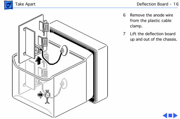
Take Apart Deflection Board - 16
6 Remove the anode wire from the plastic cable clamp.
7 Lift the deflection board up and out of the chassis.
Take Apart Power Supply - 17
Power Supply
Before you begin, do the following:• Remove the rear cover• Remove the access cover• Discharge the CRT
±
Warning:
This product contains high voltage and a high-vacuum picture tube. To prevent serious injury, review CRT safety in Bulletins/Safety.
Take Apart Power Supply - 18
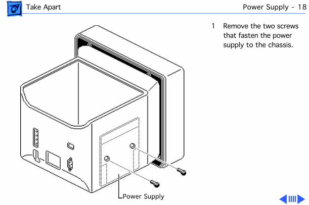
1 Remove the two screws that fasten the power supply to the chassis.
Power SupplyPower Supply
Take Apart Power Supply - 19
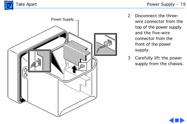
2 Disconnect the three-wire connector from the top of the power supply and the five-wire connector from the front of the power supply.
3 Carefully lift the power supply from the chassis.
Power Supply
Take Apart Fuse - 20
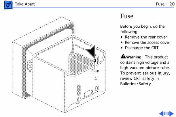
Fuse
Before you begin, do the following:• Remove the rear cover• Remove the access cover• Discharge the CRT
±
Warning:
This product contains high voltage and a high-vacuum picture tube. To prevent serious injury, review CRT safety in Bulletins/Safety.
Fuse
Take Apart Fuse - 21
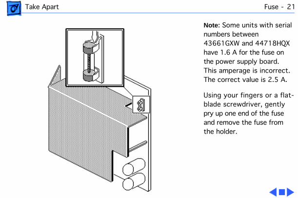
Note
: Some units with serial numbers between 43661GXW and 44718HQX have 1.6 A for the fuse on the power supply board. This amperage is incorrect. The correct value is 2.5 A.
Using your fingers or a flat-blade screwdriver, gently pry up one end of the fuse and remove the fuse from the holder.
Take Apart On/Off Switch - 22
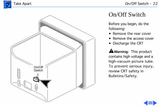
On/Off Switch
Before you begin, do the following:• Remove the rear cover• Remove the access cover• Discharge the CRT
±
Warning:
This product contains high voltage and a high-vacuum picture tube. To prevent serious injury, review CRT safety in Bulletins/Safety.
On/OffSwitch
Take Apart On/Off Switch - 23
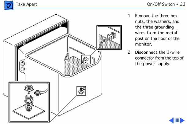
1 Remove the three hex nuts, the washers, and the three grounding wires from the metal post on the floor of the monitor.
2 Disconnect the 3-wire connector from the top of the power supply.
Take Apart On/Off Switch - 24
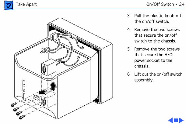
3 Pull the plastic knob off the on/off switch.
4 Remove the two screws that secure the on/off switch to the chassis.
5 Remove the two screws that secure the A/C power socket to the chassis.
6 Lift out the on/off switch assembly.
Take Apart Contrast/Brightness Assembly - 25
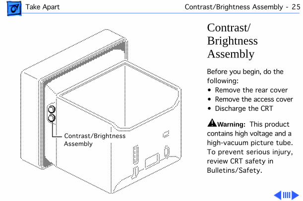
Contrast/Brightness Assembly
Before you begin, do the following:• Remove the rear cover• Remove the access cover• Discharge the CRT
±
Warning:
This product contains high voltage and a high-vacuum picture tube. To prevent serious injury, review CRT safety in Bulletins/Safety.
Contrast/Brightness Assembly
Take Apart Contrast/Brightness Assembly - 26
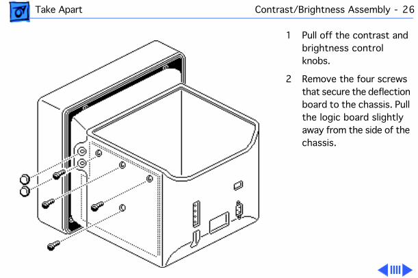
1 Pull off the contrast and brightness control knobs.
2 Remove the four screws that secure the deflection board to the chassis. Pull the logic board slightly away from the side of the chassis.
Take Apart Contrast/Brightness Assembly - 27
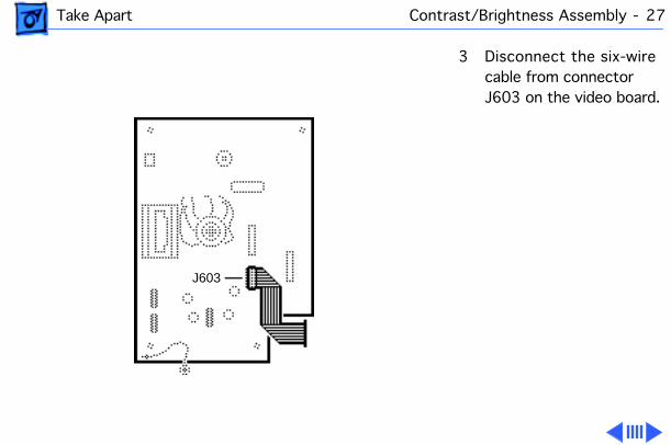
3 Disconnect the six-wire cable from connector J603 on the video board.
J603
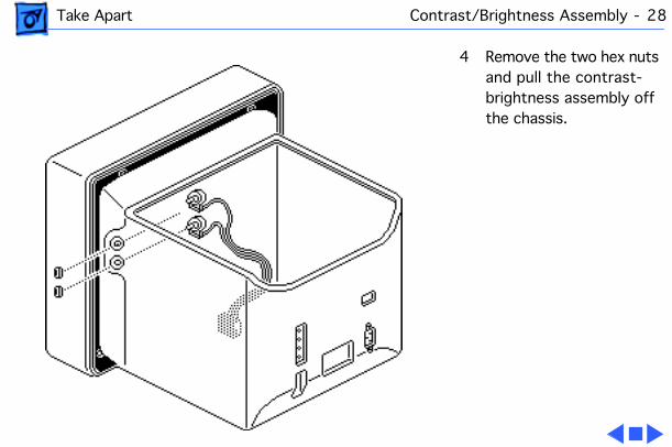
Take Apart Contrast/Brightness Assembly - 28
4 Remove the two hex nuts and pull the contrast-brightness assembly off the chassis.
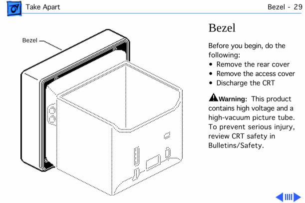
Take Apart Bezel - 29
Bezel
Before you begin, do the following:• Remove the rear cover• Remove the access cover• Discharge the CRT
±
Warning:
This product contains high voltage and a high-vacuum picture tube. To prevent serious injury, review CRT safety in Bulletins/Safety.
Bezel
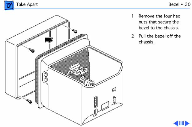
Take Apart Bezel - 30
1 Remove the four hex nuts that secure the bezel to the chassis.
2 Pull the bezel off the chassis.
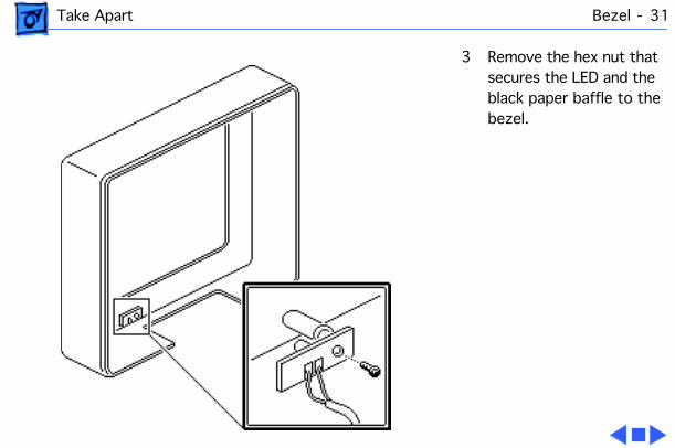
Take Apart Bezel - 31
3 Remove the hex nut that secures the LED and the black paper baffle to the bezel.
Take Apart CRT - 32
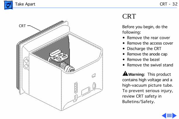
CRT
Before you begin, do the following:• Remove the rear cover• Remove the access cover• Discharge the CRT• Remove the anode cap• Remove the bezel• Remove the swivel stand
±
Warning:
This product contains high voltage and a high-vacuum picture tube. To prevent serious injury, review CRT safety in Bulletins/Safety.
CRT
Take Apart CRT - 33
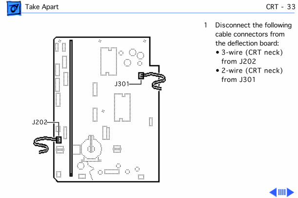
1 Disconnect the following cable connectors from the deflection board:• 3-wire (CRT neck)
from J202• 2-wire (CRT neck)
from J301
J202
J301
Take Apart CRT - 34
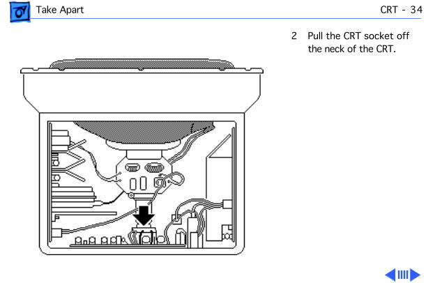
2 Pull the CRT socket off the neck of the CRT.
Take Apart CRT - 35
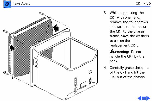
3 While supporting the CRT with one hand, remove the four screws and washers that secure the CRT to the chassis frame. Save the washers to use on the replacement CRT.
±
Warning:
Do not handle the CRT by the neck!
4 Carefully grasp the sides of the CRT and lift the CRT out of the chassis.
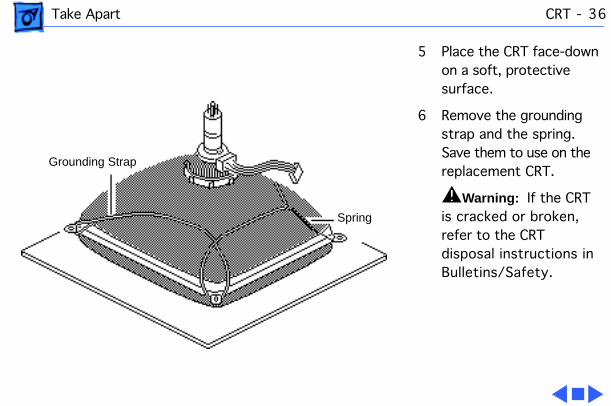
Take Apart CRT - 36
5 Place the CRT face-down on a soft, protective surface.
6 Remove the grounding strap and the spring. Save them to use on the replacement CRT.
±
Warning:
If the CRT is cracked or broken, refer to the CRT disposal instructions in Bulletins/Safety.
Grounding Strap
Spring
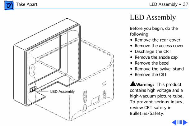
Take Apart LED Assembly - 37
LED Assembly
Before you begin, do the following:• Remove the rear cover• Remove the access cover• Discharge the CRT• Remove the anode cap• Remove the bezel• Remove the swivel stand• Remove the CRT
±
Warning:
This product contains high voltage and a high-vacuum picture tube. To prevent serious injury, review CRT safety in Bulletins/Safety.
LED Assembly
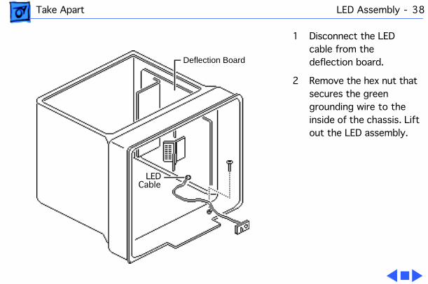
Take Apart LED Assembly - 38
1 Disconnect the LED cable from the deflection board.
2 Remove the hex nut that secures the green grounding wire to the inside of the chassis. Lift out the LED assembly.
Deflection Board
LEDCable
Service Source
K
Adjustments
Apple Two-Page MonochromeMonitor
Adjustments Geometry - 1
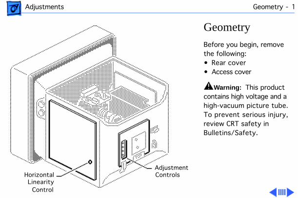
Geometry
Before you begin, remove the following:• Rear cover• Access cover
±
Warning:
This product contains high voltage and a high-vacuum picture tube. To prevent serious injury, review CRT safety in Bulletins/Safety.
HorizontalAdjustment
Control Linearity
Controls
Adjustments Geometry - 2
Warning:
Because you must make the adjustments from the rear of the computer, position a mirror to view the computer screen. Do not reach around the computer to adjust the controls.
Note:
Geometry adjustments should always be performed whenever you replace the CRT, deflection board, or video board.
Adjustments Geometry - 3
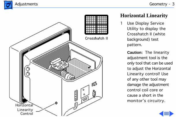
Horizontal Linearity
1 Use Display Service Utility to display the Crosshatch II (white background) test pattern.
Caution:
The linearity adjustment tool is the only tool that can be used to adjust the Horizontal Linearity control! Use of any other tool may damage the adjustment control coil core or cause a short in the monitor’s circuitry.
LinearityHorizontal
Control
Adjustments Geometry - 4
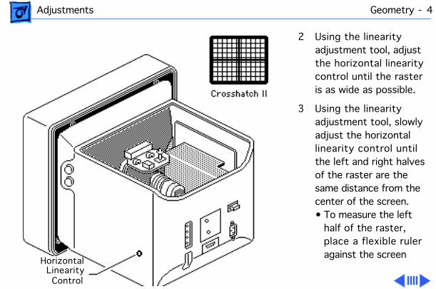
2 Using the linearity adjustment tool, adjust the horizontal linearity control until the raster is as wide as possible.
3 Using the linearity adjustment tool, slowly adjust the horizontal linearity control until the left and right halves of the raster are the same distance from the center of the screen.• To measure the left
half of the raster, place a flexible ruler against the screen
Horizontal Linearity
Control
Adjustments Geometry - 5
directly over the black horizontal line. Align the zero mark of the ruler with the left edge of the raster. Note the measurement at the point where the two black lines intersect.
• To measure the right half of the raster, align the zero mark of the ruler where the two black lines intersect. Note the measurement at the right edge of the raster.
Adjustments Geometry - 6
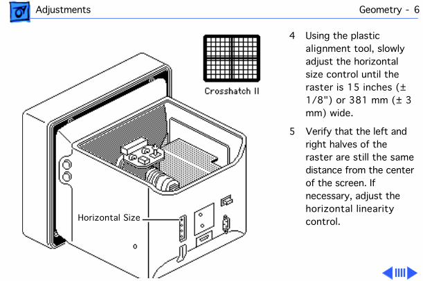
4 Using the plastic alignment tool, slowly adjust the horizontal size control until the raster is 15 inches (± 1/8") or 381 mm (± 3 mm) wide.
5 Verify that the left and right halves of the raster are still the same distance from the center of the screen. If necessary, adjust the horizontal linearity control.Horizontal Size
Adjustments Geometry - 7
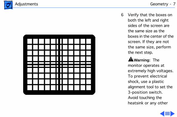
6 Verify that the boxes on both the left and right sides of the screen are the same size as the boxes in the center of the screen. If they are not the same size, perform the next step.
±
Warning:
The monitor operates at extremely high voltages. To prevent electrical shock, use a plastic alignment tool to set the 3-position switch. Avoid touching the heatsink or any other
Adjustments Geometry - 8
part of the monitor.
±
Warning:
If you do not use a plastic alignment tool, turn off the power before reaching inside the chassis and adjusting the switch. Then turn on the power and view the monitor screen.
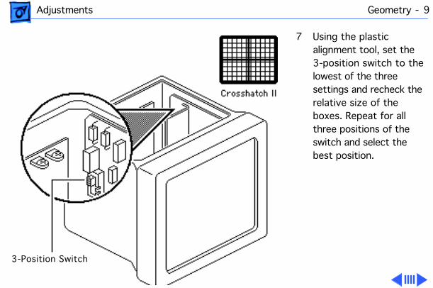
Adjustments Geometry - 9
7 Using the plastic alignment tool, set the 3-position switch to the lowest of the three settings and recheck the relative size of the boxes. Repeat for all three positions of the switch and select the best position.
3-Position Switch

Adjustments Geometry - 10
8 Using the plastic alignment tool, slowly adjust the horizontal size control until the raster is 15 inches (± 1/8") or 381 mm (± 3 mm) wide.
9 Verify that the raster is centered on the screen. If necessary, adjust the horizontal shift control.
Horizontal Size
Horizontal Shift
Adjustments Geometry - 11
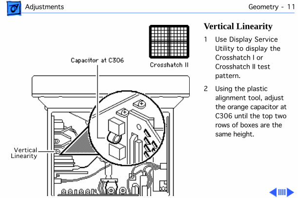
Vertical Linearity
1 Use Display Service Utility to display the Crosshatch I or Crosshatch II test pattern.
2 Using the plastic alignment tool, adjust the orange capacitor at C306 until the top two rows of boxes are the same height.
Vertical Linearity
Adjustments Geometry - 12
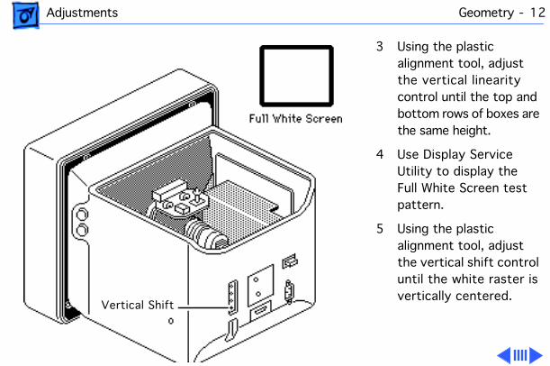
3 Using the plastic alignment tool, adjust the vertical linearity control until the top and bottom rows of boxes are the same height.
4 Use Display Service Utility to display the Full White Screen test pattern.
5 Using the plastic alignment tool, adjust the vertical shift control until the white raster is vertically centered.
Vertical Shift

Adjustments Geometry - 13
6 Use Display Service Utility to display the All-White Screen test pattern.
7 Using a plastic alignment tool, adjust the vertical size control until the white raster is 11 5/16 inches (± 1/8”) or 287.3 mm (± 3 mm) high.
Vertical Size
All-White Screen
Adjustments Geometry - 14
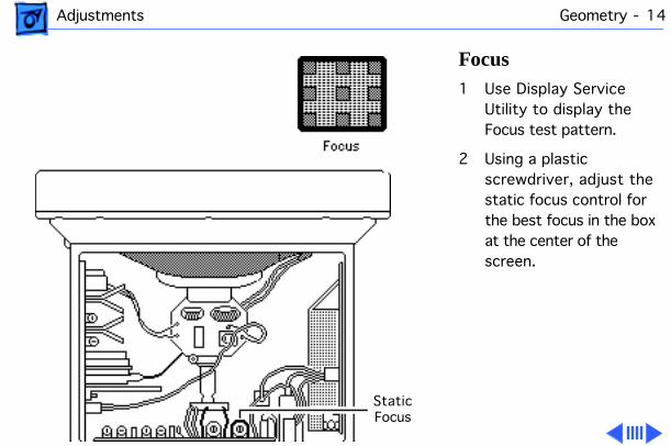
Focus
1 Use Display Service Utility to display the Focus test pattern.
2 Using a plastic screwdriver, adjust the static focus control for the best focus in the box at the center of the screen.
Static Focus
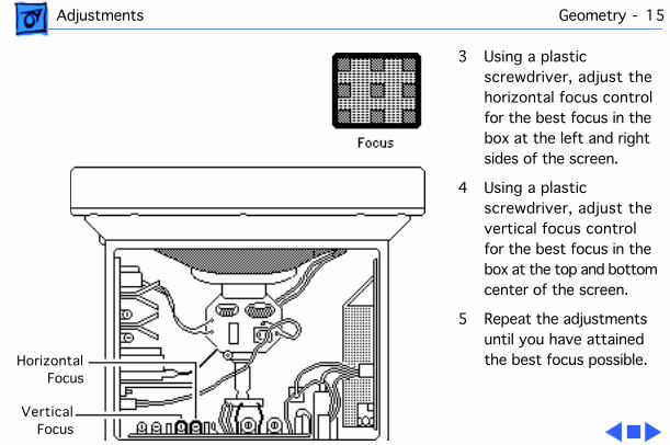
Adjustments Geometry - 15
3 Using a plastic screwdriver, adjust the horizontal focus control for the best focus in the box at the left and right sides of the screen.
4 Using a plastic screwdriver, adjust the vertical focus control for the best focus in the box at the top and bottom center of the screen.
5 Repeat the adjustments until you have attained the best focus possible.Horizontal
Focus
VerticalFocus
Adjustments Video - 16
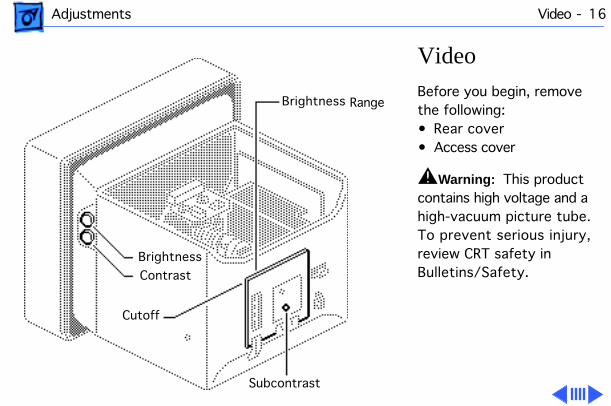
Video
Before you begin, remove the following:• Rear cover• Access cover
±
Warning:
This product contains high voltage and a high-vacuum picture tube. To prevent serious injury, review CRT safety in Bulletins/Safety.
Brightness
Brightness
Subcontrast
Cutoff
Contrast
Range
Adjustments Video - 17
Warning:
Because you must make adjustments from the rear of the computer, position a mirror to view the computer screen. Do not reach around the computer to adjust the controls.
Note:
Video adjustments should always be performed whenever you replace the CRT, deflection board, or video board.

Adjustments Video - 18
1 Switch off the power and remove the video cable from the back of the monitor.
2 Set the external (user) contrast knob to maximum (turn fully clockwise) and the brightness knob to the center (detent) position.
Brightness
Contrast
All-White Screen
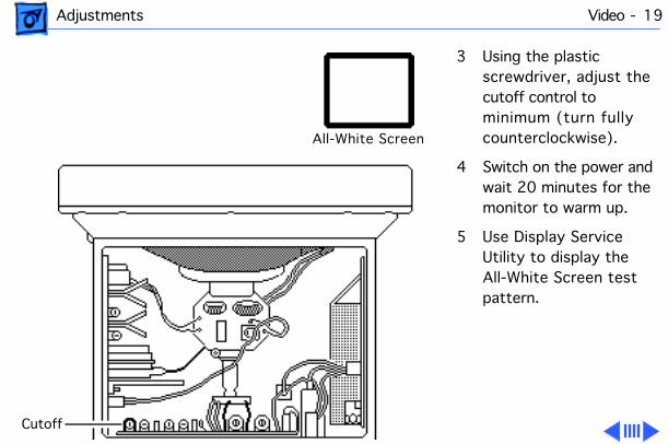
Adjustments Video - 19
3 Using the plastic screwdriver, adjust the cutoff control to minimum (turn fully counterclockwise).
4 Switch on the power and wait 20 minutes for the monitor to warm up.
5 Use Display Service Utility to display the All-White Screen test pattern.
Cutoff
All-White Screen
Adjustments Video - 20
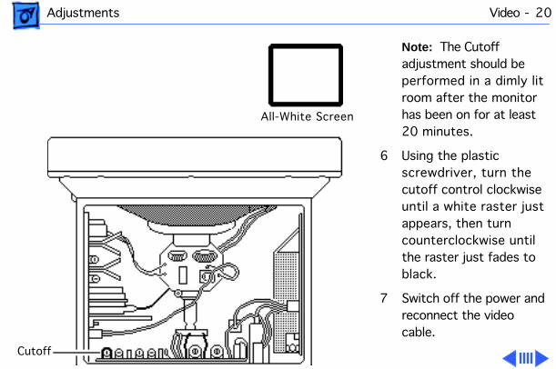
Note:
The Cutoff adjustment should be performed in a dimly lit room after the monitor has been on for at least 20 minutes.
6 Using the plastic screwdriver, turn the cutoff control clockwise until a white raster just appears, then turn counterclockwise until the raster just fades to black.
7 Switch off the power and reconnect the video cable.
All-White Screen
Cutoff
Adjustments Video - 21
8 Switch on the power.
Note:
If the power is turned off for more than a few seconds, you must wait for another 20 minutes for the monitor to warm up.
Adjustments Video - 22
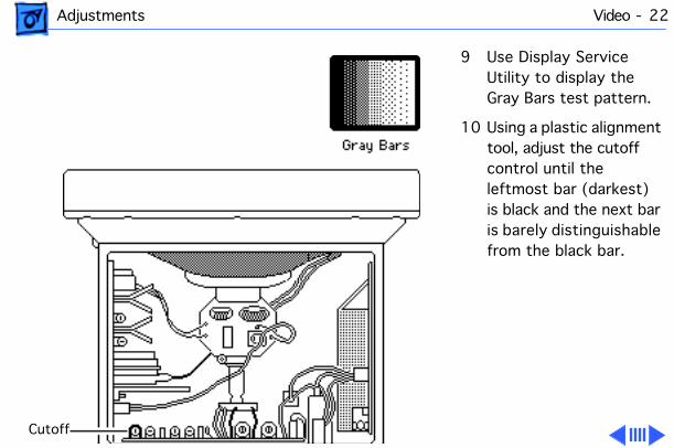
9 Use Display Service Utility to display the Gray Bars test pattern.
10 Using a plastic alignment tool, adjust the cutoff control until the leftmost bar (darkest) is black and the next bar is barely distinguishable from the black bar.
Cutoff
Adjustments Video - 23
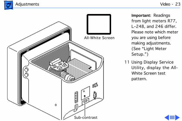
Important:
Readings from light meters R77, L–248, and 246 differ. Please note which meter you are using before making adjustments. (See “Light Meter Setup.”)
11 Using Display Service Utility, display the All-White Screen test pattern.
All-White Screen
Sub-contrast
Adjustments Video - 24
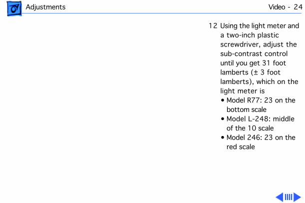
12 Using the light meter and a two-inch plastic screwdriver, adjust the sub-contrast control until you get 31 foot lamberts (± 3 foot lamberts), which on the light meter is• Model R77: 23 on the
bottom scale• Model L-248: middle
of the 10 scale• Model 246: 23 on the
red scale
Adjustments Video - 25
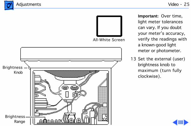
Important:
Over time, light meter tolerances can vary. If you doubt your meter’s accuracy, verify the readings with a known-good light meter or photometer.
13 Set the external (user) brightness knob to maximum (turn fully clockwise).
All-White Screen
Brightness
Brightness
Knob
Range
Adjustments Video - 26
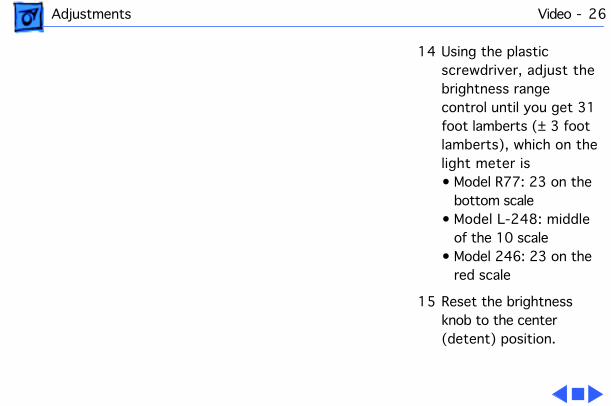
14 Using the plastic screwdriver, adjust the brightness range control until you get 31 foot lamberts (± 3 foot lamberts), which on the light meter is• Model R77: 23 on the
bottom scale• Model L-248: middle
of the 10 scale• Model 246: 23 on the
red scale
15 Reset the brightness knob to the center (detent) position.
Adjustments Light Meter Setup - 27
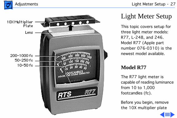
Light Meter Setup
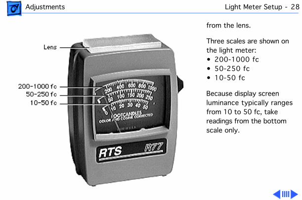
This topic covers setup for three light meter models: R77, L-248, and 246. Model R77 (Apple part number 076-0310) is the newest model available.
Model R77
The R77 light meter is capable of reading luminance from 10 to 1,000 footcandles (fc).
Before you begin, remove the 10X multiplier plate
Adjustments Light Meter Setup - 28
from the lens.
Three scales are shown on the light meter:• 200-1000 fc• 50-250 fc• 10-50 fc
Because display screen luminance typically ranges from 10 to 50 fc, take readings from the bottom scale only.
Adjustments Light Meter Setup - 29
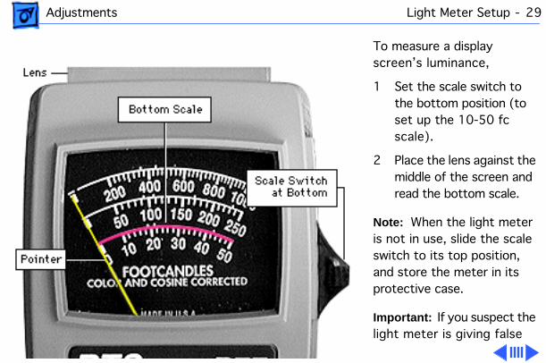
To measure a display screen’s luminance,
1 Set the scale switch to the bottom position (to set up the 10-50 fc scale).
2 Place the lens against the middle of the screen and read the bottom scale.
Note:
When the light meter is not in use, slide the scale switch to its top position, and store the meter in its protective case.
Important:
If you suspect the light meter is giving false
Adjustments Light Meter Setup - 30
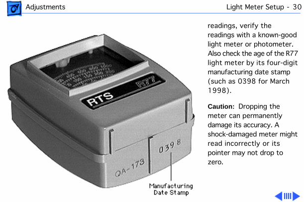
readings, verify the readings with a known-good light meter or photometer. Also check the age of the R77 light meter by its four-digit manufacturing date stamp (such as 0398 for March 1998).
Caution:
Dropping the meter can permanently damage its accuracy. A shock-damaged meter might read incorrectly or its pointer may not drop to zero.
Adjustments Light Meter Setup - 31
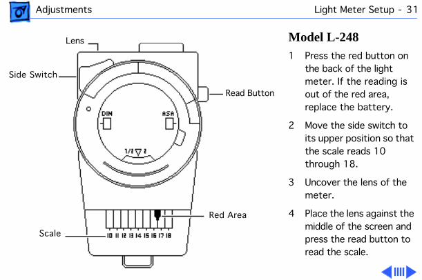
Model L-248
1 Press the red button on the back of the light meter. If the reading is out of the red area, replace the battery.
2 Move the side switch to its upper position so that the scale reads 10 through 18.
3 Uncover the lens of the meter.
4 Place the lens against the middle of the screen and press the read button to read the scale.
Read Button
Lens
Side Switch
Scale
Red Area
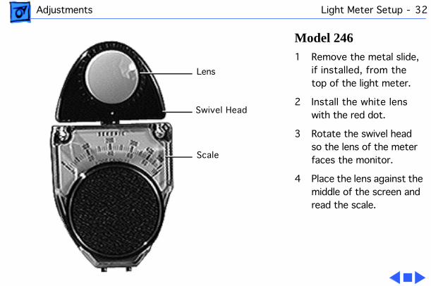
Adjustments Light Meter Setup - 32
Model 246
1 Remove the metal slide, if installed, from the top of the light meter.
2 Install the white lens with the red dot.
3 Rotate the swivel head so the lens of the meter faces the monitor.
4 Place the lens against the middle of the screen and read the scale.
Lens
Swivel Head
Scale
Service Source
K
Exploded View
Apple Two-Page MonochromeMonitor
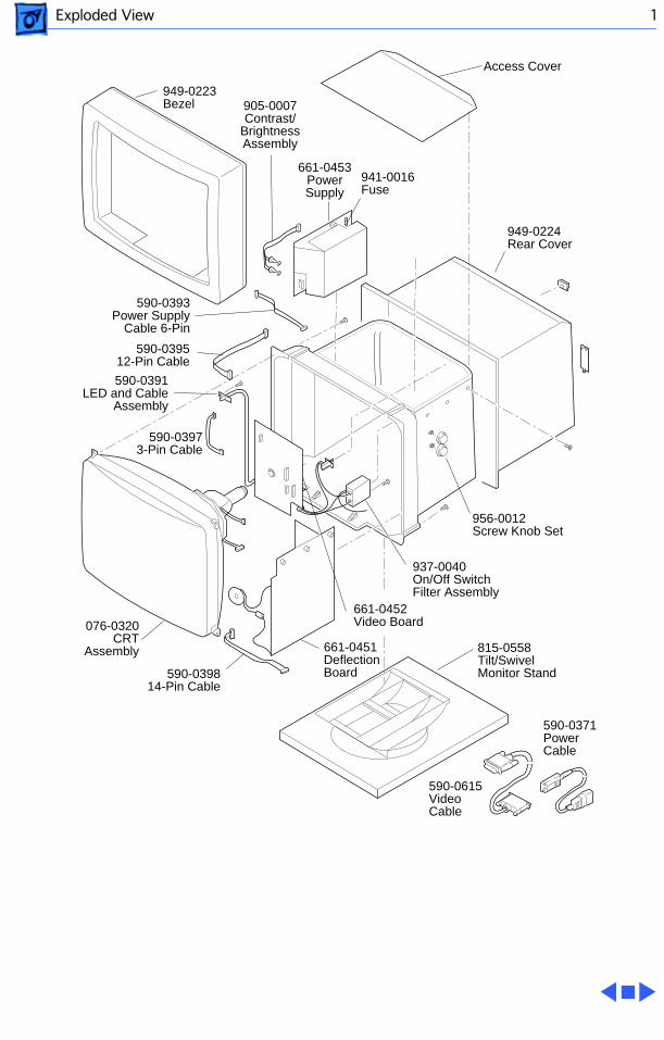
Exploded View 1
956-0012Screw Knob Set
949-0224Rear Cover
590-0371PowerCable
815-0558 Tilt/SwivelMonitor Stand
590-0615VideoCable
937-0040On/Off SwitchFilter Assembly
590-0393Power Supply
Cable 6-Pin
661-0451Deflection Board
590-03973-Pin Cable
590-039814-Pin Cable
076-0320CRT
Assembly
590-0391LED and Cable
Assembly
590-039512-Pin Cable
949-0223Bezel
661-0453PowerSupply
941-0016Fuse
905-0007Contrast/
BrightnessAssembly
661-0452Video Board
Access Cover