type 1612-al r-f capacitance meter in th is issu e · pdf file · 2017-05-27type...
TRANSCRIPT
� .... :z::
TYPE 1612-AL R-F CAPACI TANCE ME TE R
I N TH IS ISSU E Page
R IlERT F. FIELD RETm.E ......... . 6
SEE 8 AT THE
e IT IS P R 0 BA BL E that not many read
ers of the Gen ral Radio E. ·perimenter are
ver keenl aware of the standar liza ion
a ti vi tie of the RTMA (Ra li -'1' 1 \'i ion
1\1:anufactur"'rs A ocia ion), nor of the
many probl m which are posed to th ac
tive · mmitteemen as they dev 1 p th
tandards. I.R. . HOW . . . . . . A good c ·ampl f th un xpe ·ted rami
fication · of the andanlization procef:ls can
b found in the electron-tube- ocket tandar<lization work which ha.
·o fur procluce<l Standard TR-111 in the Tran mitt r 1 tion an<l will
in th n ar futur , produc a H eceivcr Se ·tion , o l· , tandard. Even
b for TR-111 actually \Ya. i . u d and \\ hil it wa · o·oing through he
u TC ive tep requir d for tandardization ·ommittee work wa. going
forward on e.·t n i n and revi 10n of 'IR-111 t keep the tandard
ali ,, and brea t of th times.
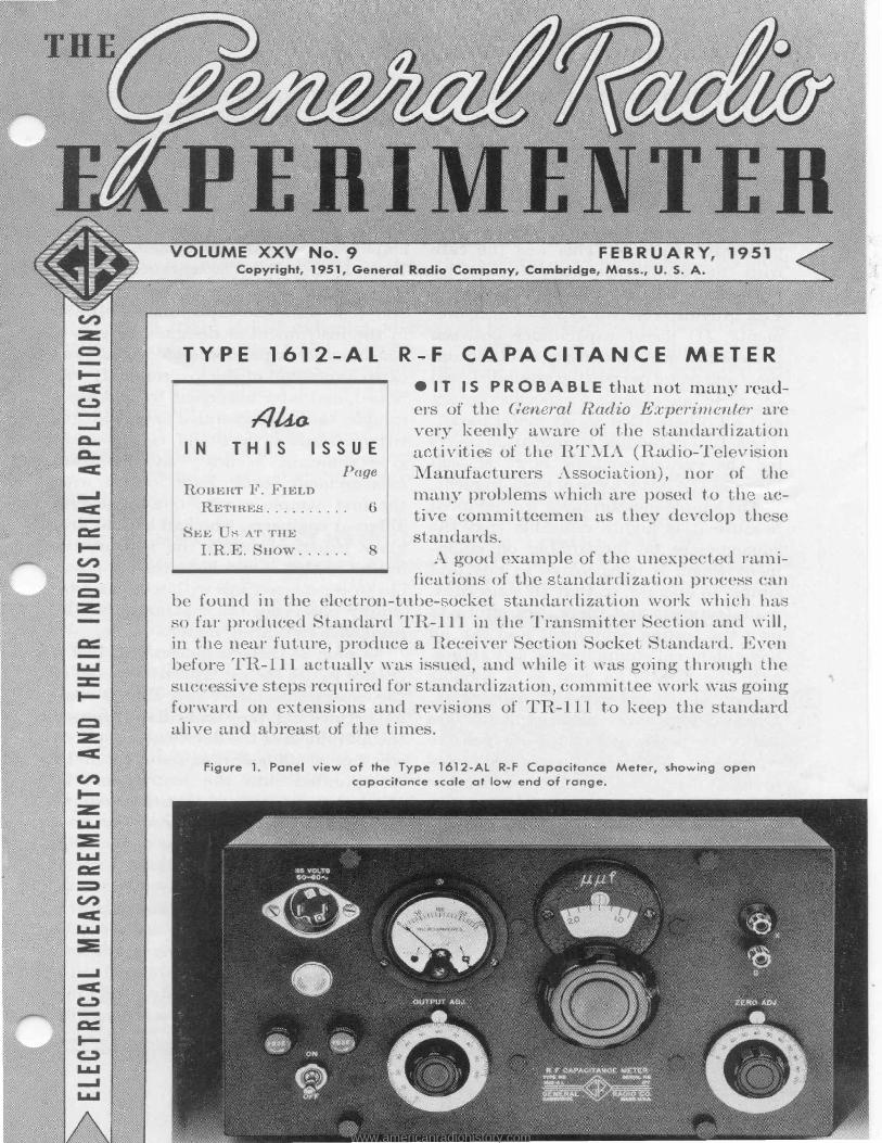
Figure l. Panel view of the Type 1612-AL R·F Capacitance Meter, showing open capacitance scale at low end of range .
www.americanradiohistory.com

GENERAL RADIO EXPERIMENTER
TEST EQUI PMENT NEEDED
ft ntime in the d velopnien o a andard i will b , b c mmon on ent,
de m d e ential to make a certain typ
of test on th i em being standardized.
Frequ n 1 the p cifi ation may re
quir te ing quipmen which i not
pre ·ently available. This wa .the ca
with the apa itance tests required by
Paragraph 4.32 of TR-111. Paragraph
4.32 provid s for two t pes of mea ure
m nt"': (1) direct capacitance between two pe ifi o ket contacts, all other con
tact and me al parts b ing grounded; and (2) capacitance betv een a spe ific contact
and all others (tied to all metal parts). The actual individual specification sheets
for the various sockets, however call
for only the latter type of measurement. The imple measurement was adopted
b ·au it is highly desirable that the
capa itance be measurable on equipment ' hich is inexpensive to buy and ·imple o operate, so that all concerned,
manufacturers and users, can afford to
own the testing equipment and can all have identical equipment so as to elimi
nate the measuring gear as a po sible
source of controversy in inspection.
Direct-capacitance measurement are -ri ky to make and require exp nsive
equipment. A simple capacitance mea -ur men from one contact to all other
me al parts, of he order of 1 µµf, is easil mad ' i h simple and inexpen iv q iip
ment. For hi reason, theref r th
individual specification h ets of TR-111 · ntain only capacitance requirements
from one contact to "all", and standardization now in proce will reduc h number of the €' mea ur m nts from tw o one.
TEST EQUI P MENT SELECTED
The capacitance values for variou
. ·o<"k t arc all f the ord r of 1 µµf. Th
2
ar ·h for th ·impl inex qu1p-m nt with which to a. fr -qu n •y of 1 c, a capacitan · f th order of 1 µµft an accurac of 0.1 µµfor
bett r wa delegated to a small t· k
group b. l e TR o ket ub •01n
mitte . � ventually it was decid d o
m loy a modifi.ca ion of G neral adi 's 'I'YPE 1612-A R-F apacitance Met r1• The TYPE 1612- has ranges of 0 µµf
and 1200 µµ f . Th capacitance network
in the in rumen t i designed to give a consid rably expanded scale at the low
capacitanc end of the low rang . It wa
hop d, and lat r borne out by making a sample, that the expanded or quasi-logarithmi scale of a 10-µµf range woul l give sufficient urac at th l-µµf
mea urem nt level. xperiment ' ith
th first sampl carried out by v ral
different engin ers, who had had no pre
vious e perienc with the instrument, indicated hat it would be readily possi
ble to repeat settings within 0.02 µµf b simply observing the maximum on th resonance-indicating meter.
As soon as these engineers had had a hance o use the experimental model of
he capacitance meter at a TR 9. com
mittee meeting, they immediately sensed
th u fulness of the d vi e and inquir d
wh ther a 100-µµf range could no be incorporat d in o th ins rument. In eff ct, the were a kino- that th m difi l
·apaci anc meter hav r ughl on -
tenth h maximum range of h nginal TYPE 1612-A. Thi wa not at all
difficult o do, and a ec nd exp rimental model ' a pr pared, embodyino- thi
added f ature. As in th case of th T PE 161 2-A, h hiftincr fr m on range o th h r i a compli hed aut -ma i all a th dial i rotated from on
half of it al ov r to the other, wi h
1 W. F. Byers," ompaC't Radio-Frcqu ncy, ap:1citan<'<'M asuring Instrum nt," reneral Rtirho E:i:r>rrit1icnl<'r,
OV rnb r, 194 .
www.americanradiohistory.com

3
no extra pan 1 witching operations. n
the 10-µµf range, the first 1 µµf occupies almost one-half of he scale length, and . ·eLting an be made to 0.02 µµf.
METHOD OF MEASUREMENT
In use he capacitance meter i prepared for a series of mea urement by
(1) setting the main dial to one or th other of the two z ro points, (2) set ing the meter for maximum by use of the zero adjust (front-righ -hand) dial, and (3) by e ting the meter to full scale by the oscillator output (lower-left-hand) dial. If now a capacitance is to be measured, it should be attached to the unknown or X terminals. The main dial 1 r tuned for maximum m t r r ading and the capacitance i indi at d directly by
the dial setting.
SOCKET MEASUREMENT METHOD
Ho, do we go about m a uring the · pacitance of a socket? The ocket, b aragraph 4.32 of TR-111, hall be
mounted on a round met 1 plate Hs" hick and 4" in diameter. Ob i u 1 h re mu be ome , ort of an adap or
i nt rposed between the binding po t of th TYPE 1()12-AL in trument and the so ket. Thi ad· ptor mu t imulate in it. proj cting c nn cting part a uh ba with whi h th so ket i Lo be u ed .
.,.n]e ad quat hi lding i pro\-rid d b r
the adap or, wo unde irable condition
will exi t: (1) mainly one of incon ni n e, in which hand capa ity bet\\'e n main or zero-adjust tuning controls and the high unknown binding post will either m I e m asur ment difficult or ':itiate it accura y; and (2), the tray
Figure 2. View showing the three s ocket adaptors, one attached to the X terminals of the capacitance meter. Internal view of adaptor at top right shows terminals, one of which is a lead for clamping in a binding post and the other a cap-
tive nut which replaces the binding-post cap.
l=EBRUARY, 1951
·apacitance between the large grounded metal plate and the high unknown binding post, of an unknown magnitude, ' ill impair the accuracy of measurem n .
For hese rea ons ea h adaptor i mad u ing an aluminum shield can as a cha -si , whi h, incidentally, provides a ready means for hiding, n.s well as containing the moun ing and wiring gear a ociated
wi h the tube base. An adaptor is attach d to the in ru
ment by screwing it on to the tud of he ground unknmvn binding post after removing the binding-post top, hrough th means of a female-threaded part
n n from the top by a screwdriver lot. urrently there are three adaptors
available, as f llow : l. 1612-Pl, for 7-pin miniatur ocl�
t , to mea ure " ..... o. contact to all. '
2. 1612-P2, for octal ock , to m a -ure ' o. 4 on act to all."
3. 16 2-P3, for 9-pin miniature nova! o ket, to mea ure":\l"o . . ') contac to all."
REDUCTIO N OF ERRORS
If you have b en con erned, a many o her working on the proj ct were, with
www.americanradiohistory.com
GENERAL RADIO EXPERIMENTER
th malln f h capa itance being
1nca ured and h con quent import
an of pr bablc rror in m a ur in nt
<lu to trav. or oth r cau c. probabl. b. now ready to a l� a qu
How ·an '""' m a ur a urat I h a
pacihtnc f a ocke thi way'? 'I h L dapt r ha an air apa i anc between
in th ca f th noYal, ay pin fiv and
all f h oth r igh , which apa itance
is 0limina eel when h o k t i plurrg d on. The o k t apa itance indica · b
the in trum nt "·ill be le. han th true
s eket capa itance by h amoun f thi · air ea:Jacitan e betw0en aclap or
pin ·. In ord r to m a ur thi capac1-tan c valu experimentally, pin were
progr i\·ely hort0n d un il th y ju
n1.ad con ta ·t with h ocke pring
1 bu reducinO' a far a po ible th air eapa ·itanc b twe n pin . Th differ nc
in mca ur ments urned out to b nl n or wo hundr dth. of a niicromi ro
f arad whic-h could appropriat ly b
neglected. , inc the ca pa i tance value
Ii. ted on th individual pecifi a ion
, h d t rmin d "vith thi fac or
L ken into a 'Coun only ariation. in
t hi. correction are pert in nt. RT:YL\ tc ndardizati n will not f r
oln iou rea. on. require th u. e of on
par i ·ular pr prietary te ting d vice.
m ndm nt t R-111 now in th RT:!YI mill howe\ r, tate ha h
1: YPI1J 1 1 2- L R- apa itan e Meter
\Yith appropriat adaptor· ha been
found to be a ati.·fa ·tor mean for
making h c· pa i anc m a urem nt
rC'quir d 1 y TR-1 11. nd th ad ntage. are obviou. in havino· all in p c-
1 or: man uf ad nr .r ' or u employ
the idC'ni ieal tC'. 1 ing C'quipmC'nt.
ZERO ADJ.
4
LOSS INDICATIO N
The 1:YrE 1 612- L pr ,·id . n ad di
ional f atur no r quir d by TR-111 namely a rouo·h indi a ion f i he los. C'. in th- ocke diel c ric.
In g-n ral, the maximum m r r ad
ing will om som "·hat b low full al .
The amoun b 'Yhi h th r '-<lino· fails o attain full cal dep nd. upon he
I in h capa ·:itan ing mea urecl. In tl ca 0 of ub o k for :in anc·0,
a little xperi n ,,·ould indi a \Yhat
would be appr priat f r di le tric . T
ver. mall am un for a r c o-la -bond d i a
1nore for a mi a-fill d
blacl
DIRECT CA PACITANCE
MEASUREMENTS
It ·hould he men ioned tha ' hil
direct or thr -t rminal apacitan ·e
m a urem nt an b 1nad w1 h th'"' capa ·i anc met r, ich me • ur men
ar n v ry conv nien n r ac urnt
'I'hre tw -terminal mea urement inn, t
be mad and the unknown cal ·ulntNl
from the r ul ino· thre equation
OTHER USES
TYPE 1 12- \L R-F "'pacitanc
no m an limited lo m a nre
ket . � umberle oth r cail. be
m n at 1 � c and ·onYeni n ·e of opcrn
ion including apacit nc rC'·1d ino· on one dial ar imp rtan .
l. 1any ramie capacitors arC' to h foun i in the rang f 0 t 100 µµf (or in
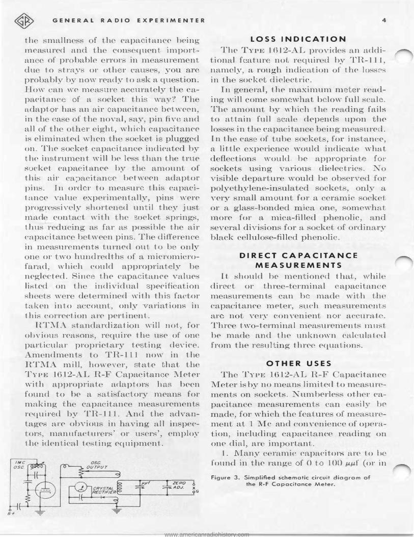
Figu..-e 3. Simplifled schematic ci..-cuit diagram of the R-F Capacitance Meter.
www.americanradiohistory.com

s
th of 0 0 JOO µµf, :if a 'IYPE 1 1 2- 1 aYailabl- a \Yell a a TYP l ( ) L.- L). Th e would in lud parat
tuhular th in ula · d nd un-
ram1 ·
tub ·oeket .
and ·he le tron-
itor ,
n
fre-
:2. , mall molded mica fix cl capa
of either foil-mi a r ilver-mi a
. tru ·tion, ean b m a ur d a a
quenc. much near r that of u han
1 kc or GO cycle w uld b .
3. Small varial l nmrn r can he aecura ly m a ur d mum and m i nimum value, r ev n for <'UlTC f capacitance rsu rotation. Thi. would apply to variable mica trim
m r. ''ariable plc. t -t p air trimm r ,
n1riablc multiple-cup-type air trimmer ,
Yariable ceramic trimmer and the an-
u, pi ton- yp '? riablC' trimmer h ,T_ ing g1a · dielec ri .
Pr caution mu t he taken, of ·our e, in providing a produ ion-typ m a urino- jig, to make , ure that no error ln m a ur men· ar introdu d by th JW it. lf or a a re ult of it con tru tion or . h.iel Ling cleficicnci0,. 'I he e tr ca
pacitance errors bceome more importan p re01 t· g wi e a i:;mall r e p.:: cite nee. ar0 being n1ea urcd.
An ther eonv nicnt u. e f r th c in
Ktrumcnt... i.· :in th a.\·c. �ment or identi-
FEBRUARY, 1951
ficat ion of in ulatino· m t ri l . · m1 1 . G n be mea ured b \Y n fl.a plate , and
an approxima Yalu of di l ri n-
tant can b c I '.Ulat d from th mea -
ured capaci ance and dimen ion of th
plat and th ample. Th dep rt urc of
th m· x1mum r adino· of th r onc.I1. c meter from f 111-� al cl fl c ion (af r of cour c prop r initial , etting) i a good
indi ·ation f th lo . . e. in th di le tric.
P ROCESS SA MP LING
'I h. R-F apa itance _ 'I te1· ha· al. o b en u ed in amplinO', f r c ntrol purP e th concentration of inoTedi nts in
ch mi al pr c ing. \.Vh r lielcet ri c pr p rti pa1· -icularly di 1 ·t ri · c< n
e u. cl a indi at r of eon
pcrio lie · mpari._on. of pr e
G mples wi h a anda1· l . ampl can
be made on th capaeitance meter. For
· hi appli ation a uiL. ble t ._ t e 11 c n
be d vised by the u er to me t hi. par-
icular requirement .
CONC LUSION
In . hort th 1 12-A and - L R-F ar Yer. a.tile> and u nd ar cxtcncht.blc in th0ir ntilit. , alrno.·t without 1imii by
the ima<>'inati< n of thE"ir owners and
u ... ·crs.
- p. J �. � (' -1 L ROY
S P ECIFICATIONS
Capacitance Range: TYPE 1 >12-A, 0 to 1200 µµf in t\Yo band.· - 0 to 0 µµf and 0 to 1200 µµf; TYPB l 612-AL, 0 to 100 µµf in tv1ro band. - 0 to 10 µµ[ and 0 to 100 µµ[. Ranges tlre. ,,·itch cl autonrnJ.icaIJ. · as ca.pacit.n,1u·c li�d ii,; rotated.
Capacitance Accuracy:
Type 1612-A
T,ow Rnngp - ±0.5 µµf h low l 0 µµ[ ±5 / h 1 ween l 0 and 0 µµ[
ITigh Ranp;P - ±5 µµf helow 100 µµf ±.5 /� lwt.wc ,n ] 00 and 1200 µµf
Type 1612-A L
Lo"· Range - ±0.05 µµf b loVI· 1 µµf ±5 Yc between 1 and 10 µµ f
High R� g - ±0.5 µµ[ b 1 \V 10 µµf ±5 hetw en 10 and 100 µµf
Capacitance Scale: ca} i;· . pr a l OU a low end of dial and near] linear at high nd. , or TYPE 1()12-A, small st division i · 1 µµf fot· th e low 1·:1.ng and 10 µµf for h high rang . F r TYPI•} l612-AL,. mall .'t sc·nl divi.�ion. ar one-tenth h ::i a1ues. Min.imUin n-1ei un hl capa<'it.ance
is influen<'ed by :-:;harpnes. of r .�onance as w 11 :•s S<'ttle distrihut.ion :1-nd is ahout. one-ha.If ilw sm:tllPst di i�ion.
www.americanradiohistory.com

GENERAL RADIO EXPERIMENTER
Dielectric losses: Relative meter indications with different dielectric samples give a comparative measure of dielectric loss.
O scillator F;equency: 1 megacycle ± 1 % adj u ted at factory. Frequency can be readjusted if ne essary by means of a movable dust core.
Resonance Indicator: A 1 N34 crystal rectifier is used with a microammeter to indicate re ·onance.
Type
6
Tube: A 117N7-GT tube i used in the oscillator circuit, and is supplied.
Power S upply: 115 volt , 50 to 60 cycles ac, or de.
Power Input: 12 watt , t 115 volt ac; 11 watts at 115 volts de. Dimensions: (Length) 12 x (height) 6% x (d pth) 7 72 inche , overall. Net Weight: 11 pound , 10 un e-.
ode W or<l P1·ic
16 12-A 16 12-AL
R-F Capc:1citance Meter ........... . ........... , R-F Cc:1pc:1citance Meter . . . . . . . . . . . . . . . . . . . . . . . .
AFTEH A<lA.1,"
$170.00 170.00
Li<'eno<e<l undC'r patent or the Radio Corporation or :\nwrir:t.
Type
1612-Pl 161 2-P2 1612-PJ
SOCKET ADAP TORS FOR USE WITH TYPE 1 6 1 2-AL ode Word Price
Adaptor for 7-pin miniature ................... . HEP'l'A 0 TAL
OVAL I $9.00
9.00 9.00
Adaptor for octal . . . . . . . . . . . . . . . . . . . . . . . . . . . . .
Adaptor for 9-pin min iat ure noval . ... ......... .
ROBERT F. FIELD RETIRES
On De b r 2 1 Ro rt F. Field
f ormall retired from the Engineering
D part1nen of he General Radio Com
pany fter 21 year of rvi e. ctually, he will b in and ou of our laboratorie for omc tim working on var10u
p r. ·onal inv tigation he ha tart d. 'I o any regular reader of the Experi
menter, Mr. Field' nam i certainly a familiar one. His contact with the engineering profe ion began long before hi a o iation vvith en ral Radio b -
after o-radua ino- from Brown i in 1906 and r · 1vmg <l
:;.\1a ter' degre th r he followino-
ar h taugh phy. i and el ctri ·al ngineerino· a Brown for a numb0r of
y ar . Then in 1 1 - h left, to take ad\'anc d work at Harv· rd �ni\'Cr::-1ity.
r iving a l\1a ·ter clegre in 19 1 t>. From 191 until h j in d th A nend Radio staff, he wa \.. i tant Profes or of ppli d Ph i · at arvard, teachin°· courses in communi ation engin ering
and pecializing in electrical measure
m nts. Mr. Field had b en with ;i nernl
Radio only thre month when the J anuary, 1930, Experimenter carried the fir of a long line of hi arti le on bridg i:; and a ociat cl ubje ·t . Thi arti ·1
Robert F. Field
www.americanradiohistory.com

7
('11 i l <l. "An Equal-Ann iapa ·itan ·
B1·idg , 'analyzed ub itution m a ur m nt with the no w v n rahl TYPE 21
During the n x - f w y ar v ral bridg
w re de ign d by Mr. Field and put into pr du tion in luding th bridcr - p
fr quen y m r, T PE 434, the 716 Capacitan ·e Bridge, th TYPE 544
l VI egohm Bridge, and probably the mo t f amou of them all - the fir t model of
th TYPE 65 -A Imp dance Bridcre -
which w s oon to become a laboratory fixture along wi h the soldering iron and
slide rule. Work with bridge circuits soon
brought him to the study of impedan e ·tandards, the measurem nt of all typ s
of impedances, and the probl ms caused
hy residual impedance in tandards and eomponents. ne impor an contribution to the art made a r sult of some of
this work was the paper pre ent d jointl. with D. B. inclair at the IRE-UR I
me ting in pril, 1 35. It wa enti led "A M thod for Determining the Resid-
ml Inductance and Resistanc of a Variable Air Conden er at adio Freq uencie " and was publi h d in h"Proceeding of the I.R.E." the follow-
1ng year. It i n t n e sary to mention all of
h in t.rument developed b t1r. Fi Id to indicate his ver atility and v r-pre -
<'nt de irn t improv mea uring techniqu , our ]'nowledcre of impedanc ·tnd the materials from which h
· n tru ed. Furthermore, the in i-
ga tion of u h cl tails a " onnection � rrors in apacitance l\II a urements"
(Januar 193 , Experimenter) k p pac witl hi 1n r t in circuit and in trum nt d ign. B-for- Ion anyon who
lidn know about th impor an e of
interfacial polarization to th elec rical eno-in er ju t hadn t come lo e to Mr.
� i ld. Th r ult of omc of hi work
FEBRUARY, 1951
ncerning polarization and it ff ·L
on the propertie o di le nc app ar l in his paper, "Th Ba i for tl N n-
De ructive Te ting f In ulation, '
whi h ' as pres nted the A IEE con-
ven ion in Toron o June 1941, and publi bed in he IEE Tran a · ion in
September 1941.
The study of insula ion and. di 1 ·tri ·
ma rials in general sub qu n ly o ·u
pied mu h of Mr. Field's time. His paper
"Th Behavior of Diel rics over Wide Ranges of Frequency, Temperature, and
Humidity" (published by eneral Radio), wa presented to many groups anxious to learn more about the mech
ani m of dielectrics and its relation to
the testing of various exi ting type of insulation. The problem of humidity
and its eff cts also was the subject of
several Experimenter articles of much interest to hos working in humid
umrner climates. And in th Ma , 1 G,
Journal of Applied Physics h pre ente l his paper on "The Formation of Ionized Water Films on Dielectrics nder on
di tions of High Humidit . "
Although many of hes tudies indicat d Mr. Fi Id's interest in capacitors
and capacitance mea urement , induc
t r were not lef ou completely, and hey ame under his scrutin . In 1ar h,
1942, with P. J(. Mc" lroy, l\1r. Field
asked in the Exp rimenter, "I-low G o 1 i an Iron- ored oil?" His Jatest contribution was presen ed to th ympo i
u1n on Improved Quality El ctr mc Component at Washington, D. 111
Ma 1950, on 'Reduction of Los. n1
ir- ored oil " I summar , however brief of :.\I 1·.
Field' contribution to t hni al lit n� -ture, should omit ref r nee o his cla i ·
pap r, " n Engineering Approach lo Trout Fishing,' which app ared in th Exp rimenler for .January, 1046.
www.americanradiohistory.com

GENERAL RADIO EXPERIMENTER
� v 'ral of ::\1.r. Fi 1 l ' colleagu . ar"
now arrang1ng o •arry on variou, a�
peel. of hi a<'ti,·e cngineerino- proor m.
::.\1r. I \'an •. Ea on will continue work
he h as 101 with Mr. Field in the ·tucl.\'
of el cc tri al in. ·ula ting ma erial. and
l riclo·e rn.ea �urement and will a um:
th o\·cr-all direction of th prooT., rn, and ::.\Ir. Ilorati \\ . Lam· n wh ha·
al.·o done considerable work in th fi ld
of in luct o r cl ign
and d v lop men t
Fi kl ha art l inclnC' or .
will carry on res2ar ·h
I rojeet which � tir.
·peciall on air-cored
S EE US AT THE
New York City
I. R. E.
BOOTHS S HOW
92 AND 93
March 19-22 1951
Plan to ,-i. it th General Radio booth
a the forthl'oming Radio Engin 'ring
Sho\Y l\Ic.tr ·h 19-22, a (Arand entrul
Pah.cc ...- ". Yorl-. ::.\Iany of th n w in ·trument an
nounced in th E. ·perirnenler durin ff th
pa. t y ar will b on di ·play-u-h-f mea -
uring quipm nt cillator bri le)'
•. ·io·nal o·enerator , v-t vol meter · d cade
irn_p <lane unit , many other·.
8
Horatio W. Lo mson Ivon G. Easton
complete \\'Orkino· di play of 'rYPE
74 axjal El m nt will b e up. u
·an how mca ur m I t of impedance
voltage, and power can b mad a u
rately and em;il. with th1 ompl t Iv
int Tated lin of 1 ment .
Man in run nt' ,,-ill ha\' tl eir
cabinet removed to d ·m n · r·tte h
high-quality l'ompon nt. · an<l con truC'-
ion in th cl u 1 in n ral Radie
quipment - the feature that give long
lif and dependable service.
H. pr ntati v f our
d partm n \Yill b n han l your q ue ti on · and di · us wi
th perf ormanc and applicati
nng
a.n w r
h you
n · f
U n ral Radi pr i n-built t t qmp-
m nL.
Plan now to ·ec thi.· di play 'f t.h '
1no. t om pl t lin of hio·h-quality te. ·t.
equipmcn · availabl t day.
GENERAL RADIO COMPANY 275 MASSACHUSETTS AVENUE
CAMBRIDGE 39 MASSACHUSETTS TELEP H 0 NE : TR owbridge 6 - 4 4 0 0
B R A N C H E N G. I N E E R I N G 0 F F I C E S NEW YORK 6, NEW YORK
90 WEST STREET
TEL.-WOrlh 2·5837
L OS ANGELES 38, CALIFORNIA
1000 NORTH SEWARD STREET
TE L.-H 0 I lywood 9-6201
CHICAGO 5, ILLINOIS
920 SOUTH MICHIGAN AVENUE
TEL. WAbash 2-3820
www.americanradiohistory.com