type 2be18b/v portable pump 2be18b/v … 2be18b/v portable pump 2be18b/v disassembly for overhaul...
TRANSCRIPT

Prepared By: EAP 60.6 Rev. # 4
Approved By: TED Date: 3/1/04
1200003
TYPE 2BE18B/V PORTABLE PUMP
2BE18B/V DISASSEMBLY FOR OVERHAUL Refer to drawing DBC0301
1. Disconnect primer tubing at the primer suction fitting (81).
2. Remove four 3/8" NC (14) nuts and remove the discharge head (19) assembly and gasket (44) from
pump casing (23).
3. Remove eight 3/8" NC nuts. Remove pump casing (23) from inboard head (43). Discard pump casing
gasket (24).
4. If necessary to replace, remove seal ring (26) from pump casing (44).
5. Remove cotter key (29), impeller nut (30), and impeller washer (28) from impeller shaft (31).
6. Pry impeller (25) from impeller shaft (31), Use two flat bars or large screwdrivers on opposite
sides of impeller. Bear against impeller where vanes provide support.
7. Remove four 3/8” NC nuts and slide inboard head (43) away from engine. Impeller shaft (31) should
stay with inboard head. Keep inboard head square with engine to avoid damage to parts.
8. Loosen packing gland nut (52).
9. Models since September 1989 have a bearing retainer ring (82) which must be removed from inboard
head (43).
10. Tap impeller shaft (31) out of inboard head (43).
11. Press bearing (37) off of impeller shaft (31).
12. Pull oil seal (40) out of inboard head (42) with a hooked seal puller.
13. If necessary y to replace, press stuffing box (42) out of inboard head (43).
PARTS INSPECTION AND MEASUREMENT
1. Clean all parts and examine carefully for wear or deterioration. Replace any questionable parts.
2. Measure the impeller seal rings and seal ring for wear. Use the following table for comparison.
Impeller Seal Ring O.D. ............................................................................... 3.304 - 3.302"
Seal Ring I.D. ............................................................................................... 3.316 - 3.314"
Clearance - original ...................................................................................... 0.010 - 0.014"
3. If clearance exceeds 0.025" on diameter, impeller seal rings can be restored to original size by soldering
a ring over trued surface which retains at least 0.090” wall thickness. Stationary seal rings should also
be replaced.

Prepared By: EAP 60.7 Rev. # 4
Approved By: TED Date: 3/1/04
1200003
4. Measure impeller shaft and stuffing box for wear. Use the following table for comparison.
Impeller Shaft diameter at packing area 1.124 - 1.125" Stuffing Box bore - new 1.130 - 1.131" Stuffing Box bore - maximum 1.136" Clearance - original 0.005 - 0.007" Clearance - maximum allowable 0.012"
5. Measure bearing housing bores for proper size. Use the following table for comparison. If any bore
exceeds the high limit by 0.0005”, the part should be replaced.
PART REP NO. ORIGINAL BORE DIA.
Inboard Head 43 3.5433 - 3.5442"
6. Measure shaft bearing journals for proper size. Use the following table for comparison. The low limit
under bearing is required to insure a press fit with inner bearing race.
PART REP NO. ORIGINAL JOURNAL DIA.
Impeller Shaft 31 2.1655 - 2.1660"
7. The original impeller shaft diameter under the impeller is 0.8740 - 0.8745”. The original impeller bore
is 0.8750 - 0.8755” providing 0.0005 - 0.0015” clearance. The parts are still serviceable up to 0.0020”
clearance.
ASSEMBLY OF TYPE 2BE18B PORTABLE PUMP
Refer to drawing DBC0301
NOTE: Apply Loctite 243 or equivalent Thread locker to all pump related threaded fasteners.
1. Apply a thin coat of Loctite 609 or equivalent to the outer surface of the stuffing box (42). Align
packing hole in stuffing box with packing hole in inboard head (43) and press stuffing box into inboard
head until seated.
2. Press oil seal (40) into inboard head (43) with lip spring of seal facing bearing. Fill grease cavity with
grease and lubricate shaft shoulder.
3. Apply a light coating of grease to bore of bearing (37) and press bearing onto impeller shaft (31) until
bearing is tight against shaft shoulder.
4. Apply grease to bearing bore of inboard head (43).
5. Slide impeller shaft (31) into inboard head (43) until bearing is seated in its pocket.
6. Models since September 1989 have a bearing retainer ring (82) which must be installed in inboard
head (43). Retainer ring must be tight in groove. Replace if loose.
7. Apply a light coating of oil to engine shaft. Place impeller shaft key (39) in engine shaft keyway. Align
keyslot in impeller shaft (31) with key and engage inboard head with studs on engine as you slide
impeller shaft over engine shaft.
8. Attach inboard head (43) to engine with four 3/8” NC nuts and lock washers on studs.

Prepared By: EAP 60.8 Rev. # 4
Approved By: TED Date: 3/1/04
1200003
9. Apply a light coating of oil to impeller shaft (31). Place impeller key (27) in impeller shaft keyway.
Align key slot in impeller (25) with impeller key, and press impeller onto impeller shaft until impeller is
tight against shaft shoulder.
10. Place impeller washer (28) onto impeller shaft (31), round side out.
11. Clean and dry shaft thread and impeller nut (30), removing dirt, grease and oil. (Loctite Klean N’
Prime, Part No. 2556, can be used to clean parts and shorten cure time of Thread locker.)
12. Apply Loctite 243 or equivalent Thread locker to shaft and nut threads.
13. Tighten impeller nut (30) until it contacts impeller washer (28), then turn to the next cotter key hole.
14. Install a 3/32" x 3/4" STAINLESS STEEL cotter key (29) into impeller shaft cotter key hole.
15. Press seal ring into pump casing (8) until seated.
16. Place casing gasket (24) into position on inboard head (43).
17. Slide pump casing (44) into position on inboard head (43). Attach to inboard head with sixteen 3/8” NC
nuts on studs.
18. Attach discharge head (19) assembly and discharge head gasket (23) to pump casing (44) with four 3/8"
NC nuts on studs.
19. Connect primer tubing at primer shut off valve.
IF FURTHER INFORMATION IS NEEDED, CALL W.S. DARLEY & CO. AT
CHIPPEWA FALLS, WI. AT 800-634-7812 or 715-726-2650


Prepared By: EAP 60.11 Rev. # 4 Approved By: TED Date: 3/1/04 1200003
PARTS LIST FOR 2BE18B/S PORTABLE PUMP
DRAWING DBC0300
Rep. Rep. No. Name of Part No. Name of Part 17 Valve Stem Packing 44 Pump Casing 18 Stuffing Box Washer Gasket 45 Check Valve Seat 19 Discharge Head 46 Check Valve Gasket 20 Check Valve Stem 47 Hex Head Cap Screws 21 Check Valve Plate 48 Valve Stem 22 Check Valve Diffuser 49 Gland Nut 23 Discharge Head Gasket 50 Stuffing Box Washer 24 Pump Casing Gasket 51 Hand wheel 25 Impeller 80 ¼ Turn Valve 26 Seal Ring 81 Primer Suction Fitting 27 Impeller Key 82 Pipe Nipple 28 Impeller Washer 83 Close Nipple 29 Cotter Key 84 Check Valve 30 Impeller Nut 85 Straight Compression Fitting 31 Impeller Shaft 86 Copper Tubing 32 Packing Cylinder 87 Gasket 33 Drain Cock 89 Exhaust Valve Body 34 Gland Nut 90 Primer Jet 35 Packing Screw 91 Spring Pin 36 Gland Stud 92 Disc Adjustment Screw 37 Bearing 93 Jam Nut 38 Pump Packing 94 Exhaust Valve Disc 39 Impeller Shaft Key 95 Primer Throat 40 Oil Seal 96 Exhaust Valve Lever 41 Grease Zerk 97 Crossover Muffler 42 Packing Box 98 Gasket 43 Inboard Head 101 90 Compression Fitting

Prepared by: TED Rev. #: 3 Approved by: MCR 1 Date: 10June2003 Revised by: AAN 1200504
W. S. DARLEY & CO. DARLEY INJECTION TYPE STUFFING BOX ADJUSTMENT
Prop 65 Warning: This product contains lead, a chemical known to the State of California to cause cancer, birth defects, and other reproductive harm. Wash hands after handling.
Caution: Do not attempt to use anything but Darley injection packing. Using the wrong packing material in your pump may cause catastrophic failure of the pump shaft sealing components.
Only use W.S. Darley & Co.’s plastallic injection packing material. It is made of a special composition of shredded fibers, and a special bonding and lubricating compound.
It is important that the stuffing box is completely filled solid with packing and compressed firm during adjustment to prevent formation of voids and excessive leakage.
To pack the stuffing box when empty and assembled in the pump, remove the packing screw and nut assembly, and insert pellet form packing into the packing plunger guide. Replace the packing screw assembly and use a hand speed wrench to force the pellets into the gland. DO NOT USE A POWER TOOL! Repeat pellet additions while turning the impeller shaft by hand until resistance to turning is felt when the stuffing box is almost full. Continue turning packing screw by hand using a standard 6" long 9/16" end wrench until 4 lb. of force is felt at the end of the wrench. This is equivalent to 2 ft-lb or 24 in-lb torque. Continue turning until a few flakes of packing are extruded out the opening between the impeller shaft and the stuffing box hole. The gland is now ready for pressure testing or pumping.
After priming the pump with water, start the pump and raise the discharge pressure to 50 psi. Tighten the packing screw using a 6" long 9/16" end wrench until 4 lb. force is felt at the end of the wrench (24 in-lb torque). Continue operating the pump at 50 psi for 5 minutes to dissipate packing pressure against the shaft and permit cooling water to flow between the shaft and stuffing box hole. Make sure that water actually does come through before operating pump at any higher pressure. The normal drip rate may vary between 5 and 60 drops per minute.

Prepared by: TED Rev. #: 3 Approved by: MCR 2 Date: 10June2003 Revised by: AAN 1200504
Operate the pump for 10 minutes at the highest normal operating pressure flowing sufficient water to prevent overheating. Do not run the pump blocked tight. Lower discharge pressure to 50 psi and repeat the packing screw tightening procedure outlined above.
The pump may now be operated for any time period required within its rated capacity. However, the drip rate should be monitored more frequently during the first few hours, and adjusted if necessary to achieve a stable flow rate. Several more adjustments may be required.
For a list of approximate quantity of packing pellets required by model (completely repacked), see below:
Model Approximate # Packing Pellets
A ………………………………………………………… 6 2BE ………………………………………………………… 6 EM ………………………………………………………… 15 H ………………………………………………………… 8
JM ………………………………………………………… 8 KD ………………………………………………………… 10 KS ………………………………………………………… 8 LD ………………………………………………………… 15 LS ………………………………………………………… 9 P ………………………………………………………… 10
U2 ………………………………………………………… 5 U4 ………………………………………………………… 10
If further information is needed, call W.S. DARLEY & CO.
at Chippewa Falls, WI. at 800-634-7812 or 715-726-2650

Prepared by: DWS Rev.: 0 Approved by: MCR 1 Date:09/25/2001 1200583
Mechanical Shaft Seal This pump assembly incorporates high quality mechanical shaft seal(s) separating the pump housing components from atmosphere. Depending on the pump design, there may be one or two seals on each impeller shaft.
The seal size, design type, component materials, and housing configuration have been specifically designed for this pump application and rated operating parameters.
Mechanical Seal Basics A mechanical seal is a device that houses two highly polished components (known as faces). One face rotates, the other is stationary. A secondary elastomer bellows seals the primary ring to the shaft. An o-ring or cup seal seals the mating ring in the housing. The polished seal faces of the primary and mating rings are pressed together by a spring mechanism to provide adequate force to affect a seal. The force acting between the seal faces increases in direct proportion to product pressure.
The elastomer bellows seal utilized in this pump has the following design features:
• Mechanical drive of the primary seal ring. The drive band’s notch design eliminates overstressing the elastomer sealing bellows.
• Bellows design provides automatic compensation for shaft endplay, run out, and primary ring wear.
• Seal face contact pressure is controlled by a single, non-clogging coil spring. This coil spring has been custom welded per Darley specifications to eliminate high-speed spring distortion.
The seal housing is designed and ported to provide optimal water flow and pressure assuring proper cooling and flushing of the seal components.
MATING RING WITH O-RING SEAL
PRIMARY RING WITH BELLOWS SEAL
SEAL COIL SPRING
WATER FLUSH PORT
IMPELLER
SEAL HOUSING

Prepared by: DWS Rev.: 0 Approved by: MCR 2 Date:09/25/2001 1200583
Operation and Maintenance When operated within rated operating conditions of this pump, these seals will provide trouble free service for extended periods.
Properly selected and applied mechanical shaft seals are leak free and require no adjustment. Should the seal area develop a leak, investigate the cause as soon as possible. Seal failure, leakage, may be the result of; worn seal faces, leaking bellows, or damaged o-rings. These failures may be attributed to bearing failure, impeller blockage, impeller imbalance, seal housing contamination, operating beyond pump design rating, or dry running,
Mechanical shaft seal design relies on the sealed media, in this case, water, to cool and lubricate the sealing surfaces. Therefore, extended dry operation may cause overheating and scoring or damage to the sealing surfaces, resulting in excessive leakage or a much shortened seal life.
To maximize seal life, minimize operation at pump pressures higher than pump rating. While operating at pressures beyond rating will not immediately damage the seal, it will increase sealing surface wear rate.
CAUTION: DO NOT RUN THE PUMP DRY EXCEPT MOMENTARILY AND AT LOW SPEEDS
CAUTION: DO NOT USE THIS PUMP FOR HOSE TESTING

Prepared by: AAN Rev.: B Approved by: TED 15-1 Date: 11/6/09 Revised by: TED (19July2010) 1201040
DARLEY
INSTALLATION OF MECHANICAL FACE SEAL WITH O’RING SPECIAL HANDLING Study the engineering layout before installing the seal. This shaft seal is a precision product and should be handled and treated with care. Take special care to prevent scratches on the lapped faces of the primary and mating ring. Provide a very clean work area where the assembly will take place. Clean hands prior to assembly. INSTRUCTION STEPS: Instructions for Installing a Mechanical Shaft Seal 1. Inspect mating ring pocket in seal housing ensuring it is clean, free of chips, and nick free, to provide a proper
sealing surface. Isopropyl alcohol may be used to clean the surfaces if required.
2. Inspect the pump shaft surface under the bellows, ensuring it is clean and nick free to provide a proper sealing
surface. Isopropyl alcohol may be used to clean surface if required.
3. Lightly lubricate the o-ring on the mating ring with a single drop of P-80 water soluble rubber lubricant (do
not over lubricate) and push it into the cavity using the recommended installation tool or other suitable plastic tube free of contaminants, firmly seating the mating ring square. Note: The polished face of the mating ring must face out – away from the pump’s gear case. Try to not touch the polished sealing face with your fingers; the oils from your fingerprint can cause the seal to leak. Remove any P-80 from the sealing face after installation.
4. Clean the mating ring surface with isopropyl alcohol to remove any fingerprints and any other contaminants left on mating ring.
The approximate size of a drop should be between the sizes of these two circles.

Prepared by: AAN Rev.: B Approved by: TED 15-2 Date: 11/6/09 Revised by: TED (19July2010) 1201040
Note: Steps 5 – 9 need to all be completed with in 15 minutes or less.
5. Apply a small drop of P-80 rubber lubricant or water-soluble lubricant (not soapy water) to the inside diameter of the bellows assembly allowing it to be pushed easily into position.
6. Clean the polished sealing face of the primary ring with a clean lint free rag with isopropyl alcohol to remove all fingerprints and other contaminants.
7. Slide a seal save, similar to X6550, over the shaft splines to ensure that the seal is not damaged during installation. Place the primary ring and lubricated bellows assembly (without the spring) on the shaft, using a proper pusher - push the assembly into position so that the seal surfaces are in contact. Remove the seal save from the shaft.
8. Put the spring in place, seated tight against the spring retainer on the primary ring.
Note: Some springs may be slightly tapered, so one end fits the seal better than the other. The end of the spring that best fits the seal should go towards the seal to ensure even spring pressure all the way around.
9. Slide impeller onto impeller shaft, engage the spring into the groove of the impeller hub and install impeller washer, impeller nut, and stainless steel cotter key.
** Reference pump configuration for individual mechanical seal instructions. ** Reference pump assembly drawings and pump assembly tips for further assembly. Note: If the seal leaks slightly after assembly, it may be necessary to run the pump for approximately 30 minutes at 50-60 psi to rinse out excess lubricant and other contaminants. Once a mechanical seal has been installed, it is recommended that it not be reused.
If further information is needed, call DARLEY in Chippewa Falls, WI. at 800-634-7812 or 715-726-2650
The approximate size of a drop should be between the sizes of these two circles.

Prepared by: TED Rev.#: 0 Approved by: TED 20.1 Date: 1-13-98 1200001
W. S. DARLEY & CO.
SOME CARE AND HANDLING INSTRUCTIONS
1. DO NOT USE THIS PUMP FOR HOSE TESTING!
2. Avoid unnecessary force and rough handling of parts during disassembly and reassembly.
3. Clean parts thoroughly and maintain free from abrasive foreign matter.
4. Keep bearings in original containers until ready to install.
5. Work with clean tools in clean surroundings during reassembly.
6. Do not bump or abrade machined surfaces, giving special care to wearing surfaces, shaft shoulders, gear and impeller hub faces, gear teeth, etc.
7. Use an arbor press for forcing press fits whenever possible. If necessary to use a hammer, use one having soft plastic heads.
8. Use suitable machined and fitted sleeves or bars for forcing or pressing ball bearings and other parts having press fits.
9. Do not press a ball bearing onto a shaft by forcing against the outer race. Heavy pressure or impact against bearing balls will damage the bearing and cause premature failure.
10. If necessary to remove a ball bearing from a shaft by forcing against the outer race, the bearing should be discarded and replaced.
11. When forcing or pressing a bearing or other part onto a tight fitting shaft, the part must be started square with the shaft and forced on squarely all the way.
12. Clean and oil bearing seats and other parts having press fits to prevent galling.
13. Keep loose parts marked or otherwise identified to avoid errors in assembly.
14. When filling the gearcase with oil, fill it with SAE80W/90 gear lube oil to the bottom of the oil level plug located on the gear case.
15. Maintain the gearcase oil level every 25 hours, or every 3 months which ever comes first, and change the oil every 50 hours, or every 6 months, which ever comes first.
IF FURTHER INFORMATION IS NEEDED, CALL W.S. DARLEY & CO. AT
CHIPPEWA FALLS, WI. AT 800-634-7812 or 715-726-2650

Prepared by: DLH 1 of 29 Rev.#: 6Approved by: Engineering Date: 4/19/05Revised by: WAH 1205529.doc
Rev Date: 16 Dec, 2015 ECO 11241
DARLEYBASIC ASSEMBLING TECHNIQUES
Work with clean tools in clean surroundings during assembly. Clean parts thoroughly and keep free from nicks and abrasions. Keep loose parts marked otherwise identified to avoid error in assembly. Bearings: Keep bearings in original containers until ready to install. Bearings/Press fits: Clean and oil bearing seats and other parts having press fits to
prevent galling. Bearings: When pressing a bearing onto a shaft, the bearing must be started
perpendicular (square) to the shaft.
Bearings: When pressing bearings onto a shaft all forces applied to the bearing need tobe applied to the inner race.
Bearings: When pressing bearings into a pocket all forces applied to the bearing need tobe applied to the outer race.
Bearings: When installing a bearing with one shield, the open side goes toward the oilcavity/gear case. Typically the single shield will be next to an oil seal.
OPEN SIDEOF BEARING

Prepared by: DLH 2 of 29 Rev.#: 6Approved by: Engineering Date: 4/19/05Revised by: WAH 1205529.doc
Rev Date: 16 Dec, 2015 ECO 11241
Bearings: When pressing a bearing onto a shaft, lightly lube the bore of the bearing andthe shaft journal for the bearing with oil. Also when installing bearings into bearingpockets, lightly lube the OD of the bearing and the bore of the bearing pocket with oil.
Bearings: If necessary to remove a ball bearing from a shaft by forcing against the outerrace, the bearing should be discarded and replaced.
Press fits: Use suitable machined pushers (The end faces of the pusher should be flat,parallel and burr free) for pressing operations.
Press fits: When pressing a part into housing (ex. Stuffing box, seal ring, etc.), the partneeds to be started perpendicular to the housing.
SUITABLEPUSHERS

Prepared by: DLH 3 of 29 Rev.#: 6Approved by: Engineering Date: 4/19/05Revised by: WAH 1205529.doc
Rev Date: 16 Dec, 2015 ECO 11241
Press fits: Use a press for forcing press fits whenever possible. If necessary to use ahammer, use one having soft plastic heads. Do not use brass or lead hammers, for theface of the hammer may easily chip or flake, contaminating the assembly, which cancause severe damage to bearings and other precision components.
Impeller Nuts: When installing impeller nuts, DO NOT use an impact wrench. Use ofimpact wrenches has proven to damage the impeller washers, impellers, and impellershafts. Proper tightening procedure is to bring it snug tight, and then tighten it to the nextavailable cotter pin hole in shaft and notch in the castle nut. Then install stainless steelcotter pin.
COTTER PIN HOLELINED UP WITHNOTCH IN CASTLENUT
STAINLESS STEELCOTTER PIN

Prepared by: DLH 4 of 29 Rev.#: 6Approved by: Engineering Date: 4/19/05Revised by: WAH 1205529.doc
Rev Date: 16 Dec, 2015 ECO 11241
Lock Washer/Lock Nut: Secure shaft so that it doesn’t rotate when tightening lock nut.Line up tab on lock washer with keyway slot in shaft and slide washer onto shaft. Screwlock nut onto shaft until snug, then turn until a tab and slot line up. Using a punch, taptab from lock washer into slot on lock nut.
PROPERFIXTURE TOHOLD SHAFT
TAB IN KEYWAYSLOT
TAB INSLOT ONLOCK NUT

Prepared by: DLH 5 of 29 Rev.#: 6Approved by: Engineering Date: 4/19/05Revised by: WAH 1205529.doc
Rev Date: 16 Dec, 2015 ECO 11241
Loctite/thread locker: When applying Loctite/thread lockers, only use one small dropper hole, unless explicitly told differently by engineering, a WI, or assembly/repairinstruction or assembly supervisor.
Loctite/thread locker: When applying Loctite/thread lockers to lock fasteners going intocaptive holes (a hole that is only open on one end), apply the thread locker to the threadsof the hole.
Loctite/thread locker: When applying Loctite/thread lockers, to lock fasteners that aregoing to be installed with a pneumatic/power wrench, apply the thread locker to thefemale threads.
Transmission Threads: Use only lock washers on captive holes. The only exception isif it is an aluminum gear case, then use Loctite 243, or equivalent, and no lock washers.
Transmission Threads: Use lock washers and Loctite 243, or equivalent, if holes aretapped thru.
Inspection Plate Fasteners: Use Loctite 243, or equivalent, on the fasteners that hold therectangular inspection plate to the side of the transmissions gear case. When installingthese fasteners, install all of the fasteners to finger tight, then torque them to a finaltorque of 72 in.-lbs. in an alternating crossover pattern.
Fastener Lock Washers and Aluminum: Do not use lock washers against aluminum.Use the appropriate thread locker instead.
Start here
Finish here
Start here
Finish here

Prepared by: DLH 6 of 29 Rev.#: 6Approved by: Engineering Date: 4/19/05Revised by: WAH 1205529.doc
Rev Date: 16 Dec, 2015 ECO 11241
O-rings/Quad rings: When installing o-rings and quad rings LIGHTLY lube with oil orsilicon grease (Dow Corning 111). Be careful not to apply too thick of a film of lubricantwhen using the silicone grease because over application of the grease can cause the o-ring/quad ring to bridge and leak.
Gear Lube: When filling the gear case with oil, fill with SAE80W/90 gear lube oil tothe bottom of the oil level plug on the gear case, or the oil level mark on the dipstick.Maintain the gear case oil level every 25 hours or 3 months, which ever comes first, andchange the oil every 50 hours or 6 months.
Oil Seal lubrication: When lubricating oil seals prior to installation, apply a minimalamount of SAE 80/W90 oil on the outside diameter of the seal and the sealing lip on theinside diameter of the seal. Do not use any lubricant other than SAE 80W/90 oil unless aDarley document dated after February 14, 2012 specifically calls it out.

Prepared by: DLH 7 of 29 Rev.#: 6Approved by: Engineering Date: 4/19/05Revised by: WAH 1205529.doc
Rev Date: 16 Dec, 2015 ECO 11241
Yoke nut installation torque for PUC and PUC-3G pumps: Torque PUC andPUC-3G yoke nuts to 300-350 ft-lb. After the yoke nut has been torqued down, check tomake sure the yoke nut engages the yoke face it bumps up against.
PUC and PUC-3G yoke nuts are tightened to 300-350 lb-ft.

Prepared by: DLH 8 of 29 Rev.#: 6Approved by: Engineering Date: 4/19/05Revised by: WAH 1205529.doc
Rev Date: 16 Dec, 2015 ECO 11241
Yoke nut torque for 1.75-12 thread, 1.25-12 thread and 7/8-14 thread yokenuts: Unless otherwise specified, torque 1.75-12 interference threaded yoke nutsto 150-200 ft-lb. Unless otherwise specified, torque all 1.25-12 thread yoke nutsto 150-200 ft-lb. Unless otherwise specified, torque all 7/8-14 interferencethreaded yoke nuts to 125 ft-lb. After the yoke nut has been torqued down, checkto make sure the yoke nut engages the yoke face it bumps up against.
1.75-12 thread yoke nuts are typically used on Midship pump.1.25-12 thread yoke nuts are typically used on ZSD & ZSP pumps.
7/8-14 thread yoke nuts are used on PTO pumps.
1.75-12 thread yoke nutPart number 4814600 shownNeeds a 2-1/4” socket to tightenTighten to 150-200 ft-lb
1.25-12 thread yoke nutPart number 4822300 shownNeeds a 1-7/8” socket to tightenTighten to 150-200 ft-lb
7/8-14 thread yoke nutPart number 4814501 shownNeeds a 1-5/16” socket to tightenTighten to 125 ft-lb

Prepared by: DLH 9 of 29 Rev.#: 6Approved by: Engineering Date: 4/19/05Revised by: WAH 1205529.doc
Rev Date: 16 Dec, 2015 ECO 11241
All 1.75-12 interference threaded yoke nuts are torqued to 150-200 ft-lb.

Prepared by: DLH 10 of 29 Rev.#: 6Approved by: Engineering Date: 4/19/05Revised by: WAH 1205529.doc
Rev Date: 16 Dec, 2015 ECO 11241
All 1.25-12 threaded yoke nuts are torqued to 150-200 ft-lb.

Prepared by: DLH 11 of 29 Rev.#: 6Approved by: Engineering Date: 4/19/05Revised by: WAH 1205529.doc
Rev Date: 16 Dec, 2015 ECO 11241
All 7/8-14 interference thread yoke nuts are tightened to 125 ft-lb.

Prepared by: DLH 12 of 29 Rev.#: 6Approved by: Engineering Date: 4/19/05Revised by: WAH 1205529.doc
Rev Date: 16 Dec, 2015 ECO 11241
After torqueing the yoke nut down, check to make sure there is not a gap between theyoke nut and the yoke.
No gaps here

Prepared by: DLH 13 of 29 Rev.#: 6Approved by: Engineering Date: 4/19/05Revised by: WAH 1205529.doc
Rev Date: 16 Dec, 2015 ECO 11241
To help with the yoke nut torqueing on midship pumps, shift the transmission into roadmode. Put a bar thru the yoke that is not being torqued down to stop the driveline from
rotating. Then the driveline will not rotate as the yoke nut is being torqued.
To help with tightening yoke nuts on PTO pumps use the tool shown in the abovepicture.

Prepared by: DLH 14 of 29 Rev.#: 6Approved by: Engineering Date: 4/19/05Revised by: WAH 1205529.doc
Rev Date: 16 Dec, 2015 ECO 11241
Place the tool over the companion flange as shown above. Make sure to finger tighten anut on one of the tool’s fasteners to secure the tool to the yoke.
Now let the tool bump up against a rigid surface and use the torque wrench to tightenthe yoke nut as shown above.

Prepared by: DLH 15 of 29 Rev.#: 6Approved by: Engineering Date: 4/19/05Revised by: WAH 1205529.doc
Rev Date: 16 Dec, 2015 ECO 11241
Recommended fastener tightening torque unless otherwise specified: The followingtables will give recommended tightening torques depending upon the fasteners material and ifa Loctite type product was used. Use these recommended tightening torques if you are notconfident torqueing a fastener. For fasteners that had a Loctite type product applied to theirthreads, use the K = .20 (Clean non-plated bolt) recommended tightening torque even if eitherthe nut or bolt was zinc electroplated.
Best practice is to; use an SAE Grade 8 bolt with an SAE Grade 8 nut, use an SAE Grade 5bolt with and SAE Grade 5 nut, use an SAE Grade 2 bolt with an SAE Grade 2 nut and usethe same bolt material as what the nut is made from.
Fastener Size Recommended tightening torque Clamp load#6 – 32 Grade 8 18 to 27 in-lb 654 to 981 lb#6 – 40 Grade 8 20 to 30 in-lb 730 to 1,095 lb#8 – 32 Grade 8 33 to 50 in-lb 1,009 to 1,513 lb#8 – 36 Grade 8 35 to 52 in-lb 1,060 to 1,591 lb
#10 – 24 Grade 8 48 to 72 in-lb 1,262 to 1,893 lb#10 – 32 Grade 8 55 to 82 in-lb 1,440 to 2,159 lb¼ - 20 Grade 8 115 to 172 in-lb 2,291 to 3,437 lb¼ - 28 Grade 8 131 to 196 in-lb 2,619 to 3,928 lb
5/16 – 18 Grade 8 20 to 29 ft-lb 3,775 to 5,662 lb5/16 – 24 Grade 8 22 to 33 ft-lb 4,181 to 6,271 lb3/8 – 16 Grade 8 35 to 52 ft-lb 5,579 to 8,369 lb3/8 – 24 Grade 8 40 to 59 ft-lb 6,324 to 9,485 lb
7/16 – 14 Grade 8 56 to 84 ft-lb 7,654 to 11,481 lb7/16 – 20 Grade 8 62 to 93 ft-lb 8,548 to 12,821 lb
½ - 13 Grade 8 85 to 128 ft-lb 10,217 to 15,325 lb½ - 20 Grade 8 96 to 144 ft-lb 11,517 to 17,275 lb
5/8 – 11 Grade 8 170 to 254 ft-lb 16,272 to 24,408 lb5/8 – 18 Grade 8 192 to 288 ft-lb 18,429 to 27,643 lb¾ - 10 Grade 8 301 to 452 ft-lb 24,081 to 36,122 lb¾ - 16 Grade 8 336 to 503 ft-lb 26,853 to 40,280 lb7/8 – 9 Grade 8 485 to 727 ft-lb 33,245 to 49,867 lb
7/8 – 14 Grade 8 535 to 802 ft-lb 36,682 to 55,023 lb1 – 8 Grade 8 727 to 1,090 ft-lb 43,614 to 65,421 lb
1 – 12 Grade 8 796 to 1,193 ft-lb 47,739 to 71,608 lbThe above table is for SAE Grade 8 fasteners, K = .20 (Clean non-plated fasteners or
Loctited zinc electroplated fasteners)
Prepared by: DLH 16 of 29 Rev.#: 6Approved by: Engineering Date: 4/19/05Revised by: WAH 1205529.doc
Rev Date: 16 Dec, 2015 ECO 11241
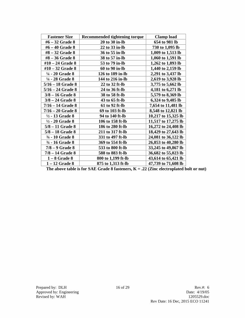
Fastener Size Recommended tightening torque Clamp load#6 – 32 Grade 8 20 to 30 in-lb 654 to 981 lb#6 – 40 Grade 8 22 to 33 in-lb 730 to 1,095 lb#8 – 32 Grade 8 36 to 55 in-lb 1,009 to 1,513 lb#8 – 36 Grade 8 38 to 57 in-lb 1,060 to 1,591 lb
#10 – 24 Grade 8 53 to 79 in-lb 1,262 to 1,893 lb#10 – 32 Grade 8 60 to 90 in-lb 1,440 to 2,159 lb¼ - 20 Grade 8 126 to 189 in-lb 2,291 to 3,437 lb¼ - 28 Grade 8 144 to 216 in-lb 2,619 to 3,928 lb
5/16 – 18 Grade 8 22 to 32 ft-lb 3,775 to 5,662 lb5/16 – 24 Grade 8 24 to 36 ft-lb 4,181 to 6,271 lb3/8 – 16 Grade 8 38 to 58 ft-lb 5,579 to 8,369 lb3/8 – 24 Grade 8 43 to 65 ft-lb 6,324 to 9,485 lb
7/16 – 14 Grade 8 61 to 92 ft-lb 7,654 to 11,481 lb7/16 – 20 Grade 8 69 to 103 ft-lb 8,548 to 12,821 lb
½ - 13 Grade 8 94 to 140 ft-lb 10,217 to 15,325 lb½ - 20 Grade 8 106 to 158 ft-lb 11,517 to 17,275 lb
5/8 – 11 Grade 8 186 to 280 ft-lb 16,272 to 24,408 lb5/8 – 18 Grade 8 211 to 317 ft-lb 18,429 to 27,643 lb¾ - 10 Grade 8 331 to 497 ft-lb 24,081 to 36,122 lb¾ - 16 Grade 8 369 to 554 ft-lb 26,853 to 40,280 lb7/8 – 9 Grade 8 533 to 800 ft-lb 33,245 to 49,867 lb
7/8 – 14 Grade 8 588 to 883 ft-lb 36,682 to 55,023 lb1 – 8 Grade 8 800 to 1,199 ft-lb 43,614 to 65,421 lb
1 – 12 Grade 8 875 to 1,313 ft-lb 47,739 to 71,608 lbThe above table is for SAE Grade 8 fasteners, K = .22 (Zinc electroplated bolt or nut)

Prepared by: DLH 17 of 29 Rev.#: 6Approved by: Engineering Date: 4/19/05Revised by: WAH 1205529.doc
Rev Date: 16 Dec, 2015 ECO 11241
Fastener Size Recommended tightening torque Clamp load#6 – 32 Grade 5 16 to 24 in-lb 589 to 883 lb#6 – 40 Grade 5 18 to 27 in-lb 657 to 986 lb#8 – 32 Grade 5 30 to 45 in-lb 908 to 1,362 lb#8 – 36 Grade 5 31 to 47 in-lb 954 to 1,432 lb
#10 – 24 Grade 5 43 to 65 in-lb 1,136 to 1,704 lb#10 – 32 Grade 5 49 to 74 in-lb 1,296 to 1,943 lb¼ - 20 Grade 5 81 to 122 in-lb 1,623 to 2,434 lb¼ - 28 Grade 5 93 to 139 in-lb 1,855 to 2,783 lb
5/16 – 18 Grade 5 14 to 21 ft-lb 2,674 to 4,011 lb5/16 – 24 Grade 5 15 to 23 ft-lb 2,961 to 4,442 lb3/8 – 16 Grade 5 25 to 37 ft-lb 3,952 to 5,928 lb3/8 – 24 Grade 5 28 to 42 ft-lb 4,479 to 6,719 lb
7/16 – 14 Grade 5 40 to 59 ft-lb 5,422 to 8,133 lb7/16 – 20 Grade 5 44 to 66 ft-lb 6,055 to 9,082 lb
½ - 13 Grade 5 60 to 90 ft-lb 7,237 to 10,855 lb½ - 20 Grade 5 68 to 102 ft-lb 8,158 to 12,236 lb
5/8 – 11 Grade 5 120 to 180 ft-lb 11,526 to 17,289 lb5/8 – 18 Grade 5 136 to 204 ft-lb 13,054 to 19,581 lb¾ - 10 Grade 5 213 to 320 ft-lb 17,057 to 25,586 lb¾ - 16 Grade 5 238 to 357 ft-lb 19,021 to 28,532 lb7/8 – 9 Grade 5 343 to 515 ft-lb 23,548 to 35,323 lb
7/8 – 14 Grade 5 379 to 568 ft-lb 25,983 to 38,975 lb1 – 8 Grade 5 515 to 772 ft-lb 30,893 to 46,340 lb
1 – 12 Grade 5 564 to 845 ft-lb 33,815 to 50,723 lbThe above table is for SAE Grade 5 fasteners, K = .20 (Clean non-plated fasteners or
Loctited zinc electroplated fasteners)

Prepared by: DLH 18 of 29 Rev.#: 6Approved by: Engineering Date: 4/19/05Revised by: WAH 1205529.doc
Rev Date: 16 Dec, 2015 ECO 11241
Fastener Size Recommended tightening torque Clamp load#6 – 32 Grade 5 18 to 27 in-lb 589 to 883 lb#6 – 40 Grade 5 20 to 30 in-lb 657 to 986 lb#8 – 32 Grade 5 33 to 49 in-lb 908 to 1,362 lb#8 – 36 Grade 5 34 to 52 in-lb 954 to 1,432 lb
#10 – 24 Grade 5 47 to 71 in-lb 1,136 to 1,704 lb#10 – 32 Grade 5 54 to 81 in-lb 1,296 to 1,943 lb¼ - 20 Grade 5 89 to 134 in-lb 1,623 to 2,434 lb¼ - 28 Grade 5 102 to 153 in-lb 1,855 to 2,783 lb
5/16 – 18 Grade 5 15 to 23 ft-lb 2,674 to 4,011 lb5/16 – 24 Grade 5 17 to 25 ft-lb 2,961 to 4,442 lb3/8 – 16 Grade 5 27 to 41 ft-lb 3,952 to 5,928 lb3/8 – 24 Grade 5 31 to 46 ft-lb 4,479 to 6,719 lb
7/16 – 14 Grade 5 43 to 65 ft-lb 5,422 to 8,133 lb7/16 – 20 Grade 5 49 to 73 ft-lb 6,055 to 9,082 lb
½ - 13 Grade 5 66 to 100 ft-lb 7,237 to 10,855 lb½ - 20 Grade 5 75 to 112 ft-lb 8,158 to 12,236 lb
5/8 – 11 Grade 5 132 to 198 ft-lb 11,526 to 17,289 lb5/8 – 18 Grade 5 150 to 224 ft-lb 13,054 to 19,581 lb¾ - 10 Grade 5 235 to 352 ft-lb 17,057 to 25,586 lb¾ - 16 Grade 5 262 to 392 ft-lb 19,021 to 28,532 lb7/8 – 9 Grade 5 378 to 567 ft-lb 23,548 to 35,323 lb
7/8 – 14 Grade 5 417 to 625 ft-lb 25,983 to 38,975 lb1 – 8 Grade 5 566 to 850 ft-lb 30,893 to 46,340 lb
1 – 12 Grade 5 620 to 930 ft-lb 33,815 to 50,723 lbThe above table is for SAE Grade 5 fasteners, K = .22 (Zinc electroplated bolt or nut)

Prepared by: DLH 19 of 29 Rev.#: 6Approved by: Engineering Date: 4/19/05Revised by: WAH 1205529.doc
Rev Date: 16 Dec, 2015 ECO 11241
Fastener Size Recommended tightening torque Clamp load#6 – 32 Grade 2 8 to 12 in-lb 300 to 450 lb#6 – 40 Grade 2 9 to 14 in-lb 335 to 502 lb#8 – 32 Grade 2 15 to 23 in-lb 462 to 693 lb#8 – 36 Grade 2 16 to 24 in-lb 486 to 729 lb
#10 – 24 Grade 2 22 to 33 in-lb 579 to 868 lb#10 – 32 Grade 2 25 to 38 in-lb 660 to 990 lb¼ - 20 Grade 2 53 to 79 in-lb 1,050 to 1,575 lb¼ - 28 Grade 2 60 to 90 in-lb 1,200 to 1,801 lb
5/16 – 18 Grade 2 108 to 162 in-lb 1,730 to 2,595 lb5/16 – 24 Grade 2 120 to 180 in-lb 1,916 to 2,874 lb3/8 – 16 Grade 2 16 to 24 ft-lb 2,557 to 3,836 lb3/8 – 24 Grade 2 18 to 27 ft-lb 2,898 to 4,347 lb
7/16 – 14 Grade 2 26 to 38 ft-lb 3,508 to 5,262 lb7/16 – 20 Grade 2 29 to 43 ft-lb 3,918 to 5,876 lb
½ - 13 Grade 2 39 to 59 ft-lb 4,683 to 7,024 lb½ - 20 Grade 2 44 to 66 ft-lb 5,278 to 7,918 lb
5/8 – 11 Grade 2 78 to 117 ft-lb 7,458 to 11,187 lb5/8 – 18 Grade 2 88 to 132 ft-lb 8,447 to 12,670 lb¾ - 10 Grade 2 138 to 207 ft-lb 11,037 to 16,556 lb¾ - 16 Grade 2 154 to 231 ft-lb 12,308 to 18,462 lb7/8 – 9 Grade 2 133 to 200 ft-lb 9,142 to 13,714 lb
7/8 – 14 Grade 2 147 to 221 ft-lb 10,088 to 15,131 lb1 – 8 Grade 2 200 to 300 ft-lb 11,994 to 17,991 lb
1 – 12 Grade 2 219 to 328 ft-lb 13,128 to 19,692 lbThe above table is for SAE Grade 2 fasteners, K = .20 (Clean non-plated fasteners or
Loctited zinc electroplated fasteners)

Prepared by: DLH 20 of 29 Rev.#: 6Approved by: Engineering Date: 4/19/05Revised by: WAH 1205529.doc
Rev Date: 16 Dec, 2015 ECO 11241
Fastener Size Recommended tightening torque Clamp load#6 – 32 Grade 2 9 to 14 in-lb 300 to 450 lb#6 – 40 Grade 2 10 to 15 in-lb 335 to 502 lb#8 – 32 Grade 2 17 to 25 in-lb 462 to 693 lb#8 – 36 Grade 2 18 to 26 in-lb 486 to 729 lb
#10 – 24 Grade 2 24 to 36 in-lb 579 to 868 lb#10 – 32 Grade 2 28 to 41 in-lb 660 to 990 lb¼ - 20 Grade 2 58 to 87 in-lb 1,050 to 1,575 lb¼ - 28 Grade 2 66 to 99 in-lb 1,200 to 1,801 lb
5/16 – 18 Grade 2 119 to 178 in-lb 1,730 to 2,595 lb5/16 – 24 Grade 2 132 to 198 in-lb 1,916 to 2,874 lb3/8 – 16 Grade 2 18 to 26 ft-lb 2,557 to 3,836 lb3/8 – 24 Grade 2 20 to 30 ft-lb 2,898 to 4,347 lb
7/16 – 14 Grade 2 28 to 42 ft-lb 3,508 to 5,262 lb7/16 – 20 Grade 2 31 to 47 ft-lb 3,918 to 5,876 lb
½ - 13 Grade 2 43 to 64 ft-lb 4,683 to 7,024 lb½ - 20 Grade 2 48 to 73 ft-lb 5,278 to 7,918 lb
5/8 – 11 Grade 2 85 to 128 ft-lb 7,458 to 11,187 lb5/8 – 18 Grade 2 97 to 145 ft-lb 8,447 to 12,670 lb¾ - 10 Grade 2 152 to 228 ft-lb 11,037 to 16,556 lb¾ - 16 Grade 2 169 to 254 ft-lb 12,308 to 18,462 lb7/8 – 9 Grade 2 147 to 220 ft-lb 9,142 to 13,714 lb
7/8 – 14 Grade 2 162 to 243 ft-lb 10,088 to 15,131 lb1 – 8 Grade 2 220 to 330 ft-lb 11,994 to 17,991 lb
1 – 12 Grade 2 241 to 361 ft-lb 13,128 to 19,692 lbThe above table is for SAE Grade 2 fasteners, K = .22 (Zinc electroplated nut or bolt)

Prepared by: DLH 21 of 29 Rev.#: 6Approved by: Engineering Date: 4/19/05Revised by: WAH 1205529.doc
Rev Date: 16 Dec, 2015 ECO 11241
Fastener Size Recommended tightening torque Clamp load#6 – 32 3 to 5 in-lb 125 to 188 lb#6 – 40 4 to 6 in-lb 140 to 210 lb#8 – 32 6 to 10 in-lb 193 to 290 lb#8 – 36 7 to 10 in-lb 203 to 305 lb
#10 – 24 9 to 14 in-lb 242 to 363 lb#10 – 32 10 to 16 in-lb 276 to 414 lb¼ - 20 22 to 33 in-lb 439 to 659 lb¼ - 28 25 to 38 in-lb 502 to 753 lb
5/16 – 18 45 to 68 in-lb 724 to 1,085 lb5/16 – 24 50 to 75 in-lb 801 to 1,202 lb3/8 – 16 80 to 120 in-lb 1,069 to 1,604 lb3/8 – 24 91 to 136 in-lb 1,212 to 1,818 lb
7/16 – 14 128 to 193 in-lb 1,467 to 2,201 lb7/16 – 20 143 to 215 in-lb 1,638 to 2,457 lb
½ - 13 16 to 24 ft-lb 1,958 to 2,937 lb½ - 20 18 to 28 ft-lb 2,207 to 3,311 lb
5/8 – 11 32 to 49 ft-lb 3,119 to 4,678 lb5/8 – 18 37 to 55 ft-lb 3,532 to 5,298 lb¾ - 10 58 to 87 ft-lb 4,616 to 6,923 lb¾ - 16 64 to 97 ft-lb 5,147 to 7,720 lb7/8 – 9 93 to 139 ft-lb 6,372 to 9,558 lb
7/8 – 14 103 to 154 ft-lb 7,031 to 10,546 lb1 – 8 139 to 209 ft-lb 8,359 to 12,539 lb
1 – 12 152 to 229 ft-lb 9,150 to 13,725 lbThe above table is for Stainless Steel, Bronze or Aluminum fasteners. By fasteners weare implying nuts or bolts – not stationary components in the clamped joint. K = .20(Clean non-plated fasteners with or without a Loctite type product)
Socket set screw size Minimum tightening torque foralloy steel socket set screws
Minimum tightening torquefor stainless socket set screws
#6 10 in-lb 7 in-lb#8 19 in-lb 16 in-lb
#10 34 in-lb 26 in-lb¼ 78 in-lb 70 in-lb
5/16 156 in-lb 130 in-lb3/8 23 ft-lb 230 in-lb
7/16 36 ft-lb 28 ft-lb1/2 51 ft-lb 42 ft-lb5/8 110 ft-lb 82 ft-lb3/4 179 ft-lb 142 ft-lb7/8 428 ft-lb 333 ft-lb1 584 ft-lb 467 ft-lb
The above table is the recommended minimum tightening torque for alloy steel andstainless socket set screws. Please note the recommended tightening torque is the samefor both fine threaded and coarse threaded set screws

Prepared by: DLH 22 of 29 Rev.#: 6Approved by: Engineering Date: 4/19/05Revised by: WAH 1205529.doc
Rev Date: 16 Dec, 2015 ECO 11241
For reference, Recommended tightening torque is found by the following equation;
T = KDP
T = Tightening torque in units of inch-pound.K = Nut factor and it is unit less.D = Nominal bolt diameter in units of inch.P = Clamp load in units of pounds.
Nut factor = K = .20 or .22 in these tables. K = .20 for clean non-plated bolts. K = .25 for zincelectroplated bolts. See IFI handbook 6th edition on page M-64 for more details.Our recommended tightening torques is intended to maintain a clamp load of 60% to 90% of the bolt’sproof load. See Mechanical Engineering Design ISBN 0-07-056888-X page 382 for more details.We assumed a Grade 8 proof load of 120,000 psi for all fasteners sizes.We assumed a Grade 5 proof load of 85,000 psi for fasteners ¼” in bolt diameter up to 1” in boltdiameter. We assumed a Grade 5 proof load of 108,000 psi for fasteners #6 up to #10 in bolt diameter.We assumed a Grade 2 proof load of 33,000 psi for fasteners larger than 3/4” in bolt diameter up to 1-1/2” in bolt diameter. We assumed a Grade 2 proof load of 55,000 psi for fasteners #6 in bolt diameterup to 5/8” in bolt diameter.We assumed a proof load of 23,000 psi for all Stainless Steel, Bronze and Aluminum materialfasteners. Sand cast 356.0-T6 aluminum has a yield strength of 24,000 psi listed in the ASMSpecialty Handbook Aluminum and Aluminum Alloys on page 720.Fastener
SizeNominal
boltdiameter
(in)
Tensilestress area
(squareinch)
Stainless,Brass, Bronzeor Aluminumproof load (lb)
SAEGrade 2
proofload (lb)
SAEGrade 5
proofload (lb)
SAEGrade 8
proofload (lb)
#6 – 32 .1380 .00909 209 500 981 1,090#6 – 40 .1380 .01015 233 558 1,095 1,217#8 – 32 .1640 .0140 322 770 1,513 1,681#8 – 36 .1640 .01474 339 810 1,591 1,767
#10 – 24 .1900 .0175 403 964 1,893 2,104#10 – 32 .1900 .0200 460 1,100 2,159 2,399¼ - 20 .250 .0318 732 1,750 2,705 3,819¼ - 28 .250 .0364 837 2,001 3,092 4,365
5/16 – 18 .3125 .0524 1,206 2,884 4,457 6,2925/16 – 24 .3125 .0580 1,336 3,194 4,936 6,9683/8 – 16 .375 .0775 1,782 4,262 6,587 9,2993/8 – 24 .375 .0878 2,020 4,831 7,465 10,539
7/16 – 14 .4375 .1063 2,445 5,847 9,036 12,7577/16 – 20 .4375 .1187 2,730 6,529 10,091 14,246
½ - 13 .500 .1419 3,264 7,804 12,061 17,028½ - 20 .500 .1599 3,679 8,797 13,596 19,194
5/8 – 11 .625 .226 5,198 12,430 19,210 27,1205/8 – 18 .625 .256 5,887 14,078 21,759 30,715¾ - 10 .750 .334 7,693 18,395 28,429 40,135¾ - 16 .750 .373 8,578 20,513 31,702 44,7557/8 – 9 .875 .462 10,620 15,237 39,247 55,4087/8 – 14 .875 .509 11,718 16,813 43,305 61,137
1 – 8 1.000 .606 13,932 19,990 51,488 72,6891 – 12 1.000 .663 15,250 21,880 56,359 79,565

Prepared by: DLH 23 of 29 Rev.#: 6Approved by: Engineering Date: 4/19/05Revised by: WAH 1205529.doc
Rev Date: 16 Dec, 2015 ECO 11241
The above image shows how SAE Grade 8 hex head bolts can be identified.
The above image shows how SAE Grade 8 hex nuts can be identified.
The above image shows how SAE Grade 5 hex head bolts can be identified.
The above image shows how SAE Grade 5 hex nuts can be identified.
The above image shows how SAE Grade 2 hex head bolts can be identified.

Prepared by: DLH 24 of 29 Rev.#: 6Approved by: Engineering Date: 4/19/05Revised by: WAH 1205529.doc
Rev Date: 16 Dec, 2015 ECO 11241
The above image shows how SAE Grade 2 hex nuts can be identified.

Prepared by: DLH 25 of 29 Rev.#: 6Approved by: Engineering Date: 4/19/05Revised by: WAH 1205529.doc
Rev Date: 16 Dec, 2015 ECO 11241
The above images show different types of zinc electroplated fasteners.
Prepared by: DLH 26 of 29 Rev.#: 6Approved by: Engineering Date: 4/19/05Revised by: WAH 1205529.doc
Rev Date: 16 Dec, 2015 ECO 11241
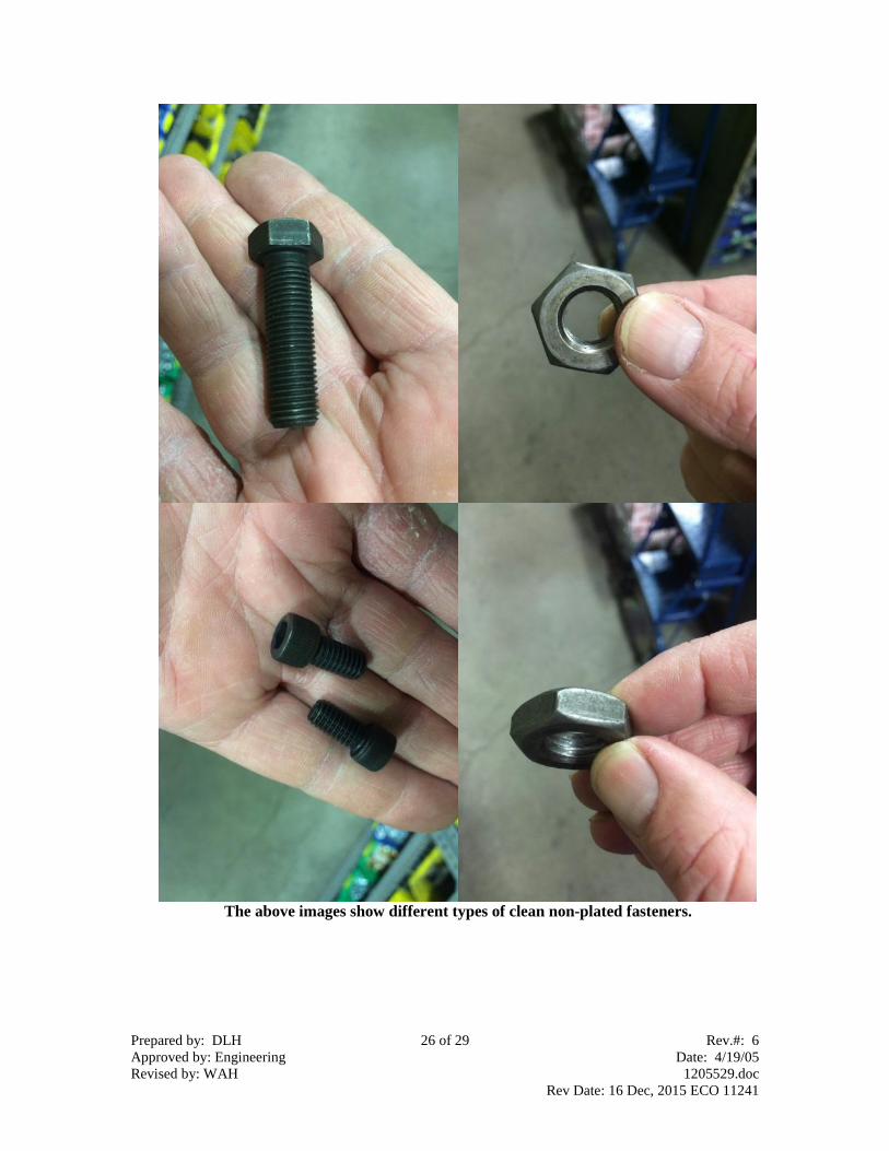
The above images show different types of clean non-plated fasteners.

Prepared by: DLH 27 of 29 Rev.#: 6Approved by: Engineering Date: 4/19/05Revised by: WAH 1205529.doc
Rev Date: 16 Dec, 2015 ECO 11241
The bolt on the left is zinc electroplated.The bolt on the right is stainless steel.
The above image is a brass machine screw and brass hex nut.
Zinc electroplated
Stainless

Prepared by: DLH 28 of 29 Rev.#: 6Approved by: Engineering Date: 4/19/05Revised by: WAH 1205529.doc
Rev Date: 16 Dec, 2015 ECO 11241
All alloy steel socket head cap screws are have an 180,000 psi tensile strength for ½” andsmaller bolts and 170,000 psi tensile strength for 5/8” and larger bolts. Use the SAE
Grade 8 recommended tightening torque tables for socket head cap screws.
All alloy steel socket flat countersunk head cap screws have a 150,000 psi minimumtensile strength. Use the SAE Grade 8 recommended tightening torque tables for alloy
steel socket flat countersunk head cap screws.

Prepared by: DLH 29 of 29 Rev.#: 6Approved by: Engineering Date: 4/19/05Revised by: WAH 1205529.doc
Rev Date: 16 Dec, 2015 ECO 11241
All alloy steel socket button head cap screws have a 137,000 psi minimum tensilestrength. Use the SAE Grade 5 recommended tightening torque tables for alloy steel
socket button head cap screws.
.
The fasteners on the left are alloy steel socket set screws. The fasteners on the right arestainless socket set screws.
If further information is needed, call Darley atChippewa Falls, WI. - 800-634-7812 or 715-726-2650
Alloy Steel
Stainless