type 92 - kerem.com.au€¦ · web viewthe information herein is confidential and the property of...
TRANSCRIPT
TYPE 92ALARM AND POWER DISTRIBUTION PANEL
(TYPE 92 APDP)
(TELSTRA S/I 353/538)
INSTALLATION / OPERATION AND MAINTENANCE HANDBOOK
090439
TELSTRA S/I 353/540
The information herein is confidential and the property of Siemens and is supplied without liability for errors and omissions. No part may be reproduced, disclosed or used except as authorised by contract or other written permission. The copyright and foregoing restriction on reproduction and use extend to all media in which the information may be embodied.
To re-order copies of this manual, the identity S48703-L3070-H1-#-76D1 should be used:
Copies may be obtained by placing an order to the following address:
Telecom Business UnitSiemens Limited885 Mountain HighwayBAYSWATER VIC 3153
Siemens LtdACN 004 347 880
S48703-L3070-H1-1-76D1

HANDBOOK REGISTRATION FORM
HANDBOOK NO S/I
HANDBOOK TITLE
ISSUE NO DATE
EQUIPMENT INSTALLED AT
USER’S NAME TEL NO
TITLE FAX NO
DIVISION/BRANCH
ADDRESS
POSTCODE
USER’S COMMENTS, PRESENTATION, CONTENTS, DELETION OR CHANGES ETC.
FOLD AND POST TO:
PRODUCT MANAGER (SERIAL 353)TRANSMISSION, PLANNING & PRODUCTS14/242 EXHIBITION STREETMELBOURNE VIC 3000
RECORDED BY:
TRANSMISSION SUPPORT BRANCH:
NETWORK OPERATIONS
SEQUENCE NO:
S48703-L3070-HI-I-76DI

S48703-L3070-HI-I-76DI
TABLE OF CONTENTS
1. GENERAL
1.1. Scope1.2. List of Abbreviations1.3. Manufacturing Label1.4. Siemens Ltd - Numbering System1.5. Symbols1.6. Status Sensitive Devices - Handling Procedures
1.6.1. Labelling1.6.2. Packaging1.6.3. Handling Precautions1.6.4. Explanation
1.7. Warranty And Repair Information1.7.1. Warranty Period1.7.2. Procedure for Handling Faulty Equipment
2. EQUIPMENT DESCRIPTION AND SPECIFICATION
2.1. Equipment Description2.1.1. Equipment Mounting2.1.2. Supply Inputs2.1.3. Supply Input Monitoring2.1.4. Subrack Feeds2.1.5. APDP Alarm Field2.1.6. Alarm Circuit Power Supply2.1.7. Subrack Alarm Power Supply2.1.8. Circuit Breakers2.1.9. Circuit Breaker Operation (Refer Figure 5)2.1.10. Circuit Breaker Alarms2.1.11. Subrack U, NU Alarms2.1.12. Alarm Receiving Attention (ARA) Indication2.1.13. Outputs to Remote Station Alarms2.1.14. Front Panel Alarm Display2.1.15. Front Panel Assembly
2.2. Specifications2.2.1. Electrical2.2.2. Connections2.2.3. Operating Temperature Range2.2.4. Mechanical
3. INSTALLATION AND TESTING
3.1. Safety Precautions3.2. Rack Mounting3.3. Cables and Terminations3.4. Switch Settings3.5. Recording on Labels
S48703-L3070-HI-I-76DI 1

4. FUNCTIONAL TESTING AND COMMISSIONING
4.1. Circuit Breakers and Alarm Priority Switching Test4.2. Alarm Input Test4.3. Remote Station Alarm4.4. Equipment Feeds
5. CIRCUIT DESCRIPTION AND MAINTENANCE PROCEDURE
5.1. Circuit Description5.1.1. Supply Distribution5.1.2. Origin and Display of Alarm Conditions5.1.3. Voltage Monitoring (Refer Figure 10).5.1.4. U, NU, ARA Alarm Monitoring5.1.5. Alarm Display
5.2. Maintenance Procedure5.2.1. Localising Faults5.2.2. Removing Alarm / LED Boards5.2.3. Reliability of Motherboard5.2.4. Repair Under Warranty
6. PARTS LIST
001647 APDP TYPE 92 S353/538022383 PBA MOTHERBOARD APDP TYPE 92022384 PBA ALARM BOARD APDP TYPE 92022384 PBA ALARM BOARD APDP TYPE 92022385 PBA LED BOARD APDP TYPE 92022420 PBA SCREEN TRM ASSY022428 HSNG ASSY APDP TYPE 92022434 CVR FNT ASSY APDP TYPE 92022435 PWR TRM ASSY APDP TYPE 92
7. DRAWINGS
Figure 1: List of AbbreviationsFigure 2: Type 92 APDP General ViewFigure 3: Type 92 APDP DimensionsFigure 4: Cover Front and Rear ViewFigure 5: Circuit Breaker OperationFigure 6: Type 92 APDP Alarm FieldFigure 7: Circuit Breaker Trip TimeFigure 8: Battery Input Cable TerminationFigure 9: Type 92 APDP Motherboard SchematicFigure 10: Type 92 APDP Alarm Board SchematicFigure 11: Type 92 APDP LED Board SchematicFigure 12: Type 92 APDP Motherboard Assembly
S48703-L3070-HI-I-76DI 2

1 GENERAL
1.1 Scope
This handbook contains information for the Type 92 Alarm and Power Distribution Panels (Telstra S/I 353/538) in respect of:-
· equipment description and specification.· installation.· operation.· circuit description and maintenance procedures.· warranty and repair information.
Separate handbooks, such as Operator Handbook, Repair Handbook, and Operation and Maintenance Guide are NOT provided for the Type 92 Alarm and Power Distribution Panel.
1.2 List of Abbreviations
A list of the abbreviations used in this handbook is provided in Figure 1.
1.3 Manufacturing Label
The manufacturing label is located at the left hand side panel of the T92 APDP (Figure 2 ref D2). The label provides the following information:
· The name of the manufacturer.· The month and year of manufacture.· Telstra serial number and item number.· Bar code identification label for the T92 APDP.
A sample of the manufacturing labels are shown below:
S48703-L3070-H1-1-76D1 1

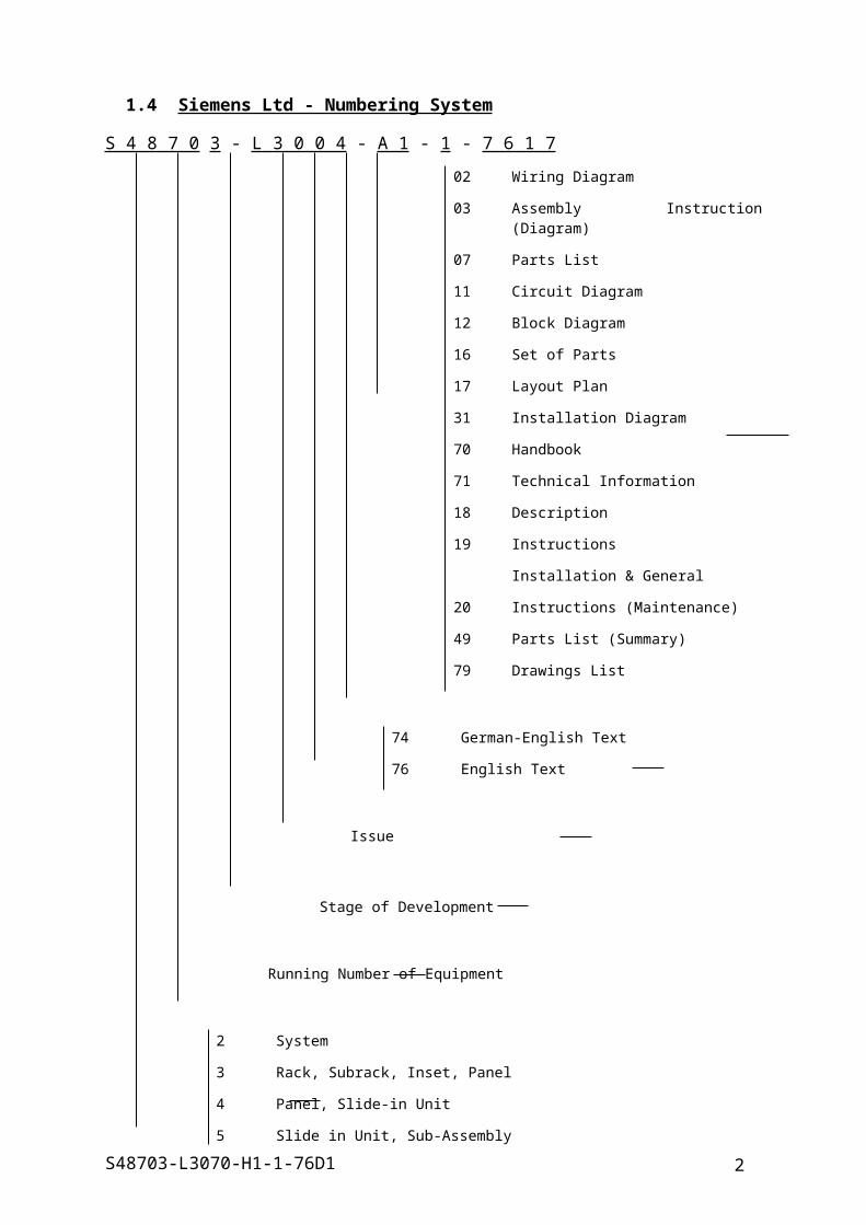
1.4 Siemens Ltd - Numbering System
S 4 8 7 0 3 - L 3 0 0 4 - A 1 - 1 - 7 6 1 7
02 Wiring Diagram
03 Assembly Instruction (Diagram)
07 Parts List
11 Circuit Diagram
12 Block Diagram
16 Set of Parts
17 Layout Plan
31 Installation Diagram
70 Handbook
71 Technical Information
18 Description
19 Instructions
Installation & General
20 Instructions (Maintenance)
49 Parts List (Summary)
79 Drawings List
74 German-English Text
76 English Text
Issue
Stage of Development
Running Number of Equipment
2 System
3 Rack, Subrack, Inset, Panel
4 Panel, Slide-in Unit
5 Slide in Unit, Sub-Assembly
6 Small Sub-Assembly
S.I.L. Works Design Code
S48703-L3070-H1-1-76D1 2

1.5
S48703-L3070-H1-1-76D1 3
1.6 Symbols
S48703-L3070-H1-1-76D1 4

1.7 Status Sensitive Devices - Handling Procedures
1.7.1 Labelling
a. Packing boxes or cartons used for the delivery of equipment units which contain static sensitive devices are labelled as followed, in yellow or orange:
b. Slide-in units which contain static sensitive devices are delivered in a special bag labelled as follows or in an antistatic container marked as in 1.6.1.a above.
c. Slide-in units which contain static sensitive devices are labelled with the following symbol (shown enlarged for clarity when dimensions and actual size):
S48703-L3070-H1-1-76D1 5

1.7.2 Packaging
Equipment containing static sensitive devices is delivered from the factory packaged as indicated below. Bearing in mind that it may be necessary to transfer this equipment to another location or return units to the factory for repair, arrangements should be made to retain as much of the packaging materials as may be needed.
For transportation within a station, units should be enclosed in their special bags or containers.
For transportation outside a station, the special bags should be used and packed in their appropriate cartons or boxes.
1.7.3 Handling Precautions
Generally when handling equipment with units containing static sensitive devices, avoid contact with the components or connectors.
When inserting or removing units, discharge static from the person by touching panel or other earthed metalwork eg: rack.
DO NOT place units on non-conducting surfaces, eg: plastic bench tops.
DO NOT use a brush or air jet to remove foreign matter eg: dust etc, from within the unit.
1.7.4 Explanation
Static Sensitive Devices generally are integrated circuits which operate on very low power. The junctions to which leads may be connected have very low capacitance (a few pF), but extremely high leakage resistances (the time constant may be measured in days!). To achieve these characteristics it is unavoidable that they have low breakdown voltages, eg: 20V. Internal protection is provided by means of isolation resistors in series with the pins and diodes connected to the supply rails. This ensures the security of the device in well designed circuits. The real danger in practice comes from the ability of high quality insulating, furnishing and dress materials to generate and store high voltage charges through friction and the transfer of these charges through the human body which has a capacitance of about 300pF. For example, in dry conditions walking on a plastic floor or nylon carpet, or rubbing nylon clothing on a laminated bench, can generate static voltages as high as 15kV. Because the body capacitance is so large compared with the junction capacitance, there is very little loss of voltage in transferring charge to the junction from the body and this can result in failure.
S48703-L3070-H1-1-76D1 6

1.8 Warranty And Repair Information
1.8.1 Warranty Period
Warranty for the T92 APDP is 19 months from the date of manufacture. As a guide the month of delivery is indicated on the left hand side panel.
For example: equipment manufactured in June 1995 stamped with : AU 0695.
1.8.2 Procedure for Handling Faulty Equipment
All faulty equipment including Printed Board Assemblies (PBAs) must be returned to:-
Siemens Limited885 Mountain HighwayBAYSWATER VIC 3153Att: Repair Centre Building II
Each faulty equipment and / or PBA must be accompanied by a detailed fault report.
Faulty equipment detected during installation should also be returned to the above address. The fault report should state that the fault was detected during installation / commissioning.
S48703-L3070-H1-1-76D1 7

2 EQUIPMENT DESCRIPTION AND SPECIFICATION
2.1 Equipment Description
The Type 92 Alarm and Power Distribution Panel (T92 APDP) provides the following functions:
· Distribution of power from the exchange secondary distribution system, via suitably rated circuit breaker protected outputs to the subrack equipment mounted in Type 92, Type 84, 19 inch or ETSI racks.
· Alarm distribution and interface facilities from the subracks to the Exchange Alarm Scheme and to the Alarm Management Systems.
· Protection of subrack equipment.· Visual indication of urgent alarm, non-urgent alarm, alarm receiving attention, and
power supply normal status.· Subrack alarm power supply protected by a 1 ampere circuit breaker for powering
subrack alarm circuits.· Provision for different values of circuit breaker - from 1 ampere up to 16 ampere, to
be used in the same circuit breaker socket for special applications.
A general view of the T92 APDP is shown in Figure 2.
2.1.1 Equipment Mounting
The Type 92 APDP incorporates reversible mounting brackets and is suitable for mounting in Type 92, Type 84, 19 inch or ETSI rack.
Refer Figure 3 for overall and mounting dimensions.
2.1.2 Supply Inputs
Two pairs of 48V power input terminals (Figure 2 grid L7) are provided for two separate power input sources: Rack Feed No 1 (RF1), and Rack Feed No 2 (RF2). See also Figure 8 for battery input cable terminations.
2.1.3 Supply Input Monitoring
The T92 APDP monitors the input supply voltages of RF1 and RF2 and generates the alarms shown in the following table for input voltages outside the normal operating range of 38.5V to 65.0V, when the voltage sense switch SW3 (Figure 2 grid F13) on the Alarm Board is set to ON.
When supply input monitoring is not required (eg: when RF2 is not used), set the appropriate SW3 switch to OFF.

Supply Input
U NML Station Urgent Alarm Alarm BOARD LED
RF1 RF2 LED LED STA(U) RF1/UV RF1/OV
RF2/UV RF2/OV
N N OFF ON OFF OFF OFF OFF OFF
L N ON OFF ON (If enabled) ON OFF OFF OFF
N L ON OFF ON (If enabled) OFF OFF ON OFF
L L ON * OFF ON (If enabled) ON * OFF ON * OFF
H N ON OFF ON (If enabled) OFF ON OFF OFF
N H ON OFF ON (If enabled) OFF OFF OFF ON
H H ON OFF ON (If enabled) OFF ON OFF ON
L H ON OFF ON (If enabled) ON OFF OFF ON
H L ON OFF ON (If enabled) OFF ON ON OFF
Note: N: Normal Supply input between 38.5V and 65.0V.L: Low or OFF. Supply input below 38.5V.H: High. Supply input above 65.0V.*: LED ON is subject to supply input voltage.
2.1.4 Subrack Feeds
Eight protected subrack feeds (-48V and 0V) are available for each of the two rack feeds RF1 and RF2 (16 in total). Each subrack feed is protected by a suitably rated plug in circuit breaker. The subrack feed terminals are located on the Motherboard (Refer Figure 2 grid F2-F5 and Figure 12 grid C3-C9).
2.1.5 APDP Alarm Field
The APDP Alarm Field is located on the right hand side of the Motherboard (Refer Figure 12, area covered by grid C, D, E and 11-14). It comprises twenty-four 4 pole insulation displacement connectors arranged in 3 rows by 8 columns, providing a total of 96 terminals. The terminals are identified by a 12 row (A to M) by 8 column (1 to 8) matrix. Connections associated with the terminals are shown in Figure 6. For example;
CBA1: Circuit breaker alarm from circuit breaker 1 is connected to terminal identified by row E and column 1.

2.1.6 Alarm Circuit Power Supply
The alarm circuit in the T92 APDP is powered via a diode wired-or circuit from both RF1 and RF2. The power supply is protected by a 1 ampere circuit breaker (labelled CB17). With dual power feeding from RF1 and RF2, the alarm circuit continues to operate if only one rack feed fails.
2.1.7 Subrack Alarm Power Supply
The alarm circuit power supply in section 2.1.6 is extended to the S- and S+ terminals of the APDP Alarm Field (refer section 2.1.5). The power supply can be used to power external subrack alarm circuits. Connections to the power supply are:
-48V: S- (1 to 4) at IDT A1 to D1 (blue marked terminals). Refer Figure 12 grid C11.
Earth (+VE): S+ (1 to 4), at IDT A2 to D2. Refer Figure 12 grid C12.
2.1.8 Circuit Breakers
The T92 APDP is designed to operate with ETA series 3600 thermal magnetic circuit breakers in accordance with customer (Telstra) requirements, to protect the subrack feeds and alarm circuit power supply. Circuit breakers with current ratings up to 16 amperes can be purchased separately and installed in circuit breaker socket positions CB1 to CB16. (CAUTION: Maximum current rating per rack feed is 48 amperes). The alarm circuit breaker in socket position CB17 shall always be 1 ampere.
2.1.9 Circuit Breaker Operation (Refer Figure 5)
The circuit breaker is equipped with two buttons:
· a three position black mode of operation button for “OFF” “ARA” and “ON”.· a red reset button.
CAUTION: Avoid reset of circuit breakers (by accidental contact with the reset button) during installation or maintenance.
a. “OFF” (black button fully extended)
· when circuit breaker is tripped due to overload condition or :· manually tripped by pushing the reset button.
In the “OFF” position.
· subrack feed is disconnected.· circuit breaker alarm (CBA) is extended to the APDP Alarm Field.· alarm receiving attention (ARA) contact is disconnected.

b. ARA (black button depressed to intermediate position)
· subrack feed is disconnected.· CBA contact is disconnected.· ARA contact is connected to the Alarm Board.
c. ON (black button fully depressed)
· subrack feed is connected.· CBA contact is disconnected.· ARA contact is disconnected.
d. Reset (red button fully depressed)
· circuit breaker is in the “OFF” position.
CAUTION: Avoid accidental reset as subrack feed is disconnected in the reset state.
NOTE: If a circuit breaker position is not to be used, the circuit breaker must be removed to avoid generation of ARA or CBA alarms.
2.1.10 Circuit Breaker Alarms
When a circuit breaker trips (OFF position), a circuit breaker alarm (CBA) is extended to the APDP Alarm Field. A CBA can have its priority defined as Urgent (U) or Non-Urgent (NU) by setting the corresponding circuit breaker switch of SW1 and SW2 (Figure 2 grid G6, also Figure 12 grid C10 and D10) to the left (for U) or to the right (for NU).
For circuit breaker alarm 1 to 16 (CBA1-16):
· U or NU LED on the T92 APDP front panel turns ON.· An Earth is extended to the rack common alarm [RCA(U) or RCA(NU)] and
station alarm [STA(U) or STA(NU)] terminals of the APDP Alarm Field.
For circuit breaker alarm 17 (CBA17: Alarm for Alarm Circuit power supply):
· All LEDs on the T92 APDP turns OFF.· An Earth is extended to the under-voltage alarm (UVA) terminal, RCA(U) terminal
and STA(U) terminals of the APDP Alarm Field. (Refer Figure 6).

2.1.11 Subrack U, NU Alarms
Urgent (U) and Non-Urgent (NU) alarm inputs from the equipment subracks can be terminated on the U1-U16 and NU1-NU16 terminals of the APDP Alarm Field (Refer Figure 6).
For subrack alarms U1-U16, NU1- NU16:
· U or NU LED on the T92 APDP front panel turns ON.· An Earth is extended to the RCA(U) or RCA(NU) terminal, and STA(U) or
STA(NU) terminal of the APDP Alarm Field.
2.1.12 Alarm Receiving Attention (ARA) Indication
An ARA is raised by either:
· Setting the circuit breaker to the ARA (intermediate) position after the circuit breaker is tripped (Refer Section 2.1.9) or:
· Earthing an ARA input terminal (ARA1 -ARA16) of the APDP Alarm Field (Refer Figure 6).
An ARA allows the technician to indicate to the remote monitoring centre that action is being taken on an alarm condition.
When an ARA is raised:
· The green bar ARA LED on the front panel alarm display turns ON, and· An Earth is extended to the RCA(ARA) and STA(ARA) terminals of the APDP
Alarm Field (Refer Figure 6).
2.1.13 Outputs to Remote Station Alarms
Remote U, NU and ARA alarms are activated by extending an Earth via the STA(U), STA(NU) and STA(ARA) terminals (or RCA(U), RCA(NU) and RCA(ARA) terminals) of the APDP Alarm Field. (Refer Figure 6).

2.1.14 Front Panel Alarm Display
Indicator Status MeaningGreen NML (Normal) Rack Feed input(s) are between -38.5V and 65V.Amber NU (Non Urgent) a. Circuit breaker classed Non Urgent has tripped.
orb: A Non-Urgent alarm input has been received
from the subrack being fed.Red U (Urgent) a. One of the supply inputs has failed or is below -
38.5V or above -65V (LEDs on the Alarm Board will indicate which input).or
b. Circuit breaker classed Urgent has tripped.or
c. An Urgent alarm input has been received from the subrack being fed.
Green Bar ARA (Alarm Receiving Attention) activated by technician Earthing an ARA input.
Remote alarm (if enabled) will show corrective action is in progress.
All Indicators
OFF
a. Both rack feed inputs have failed. orb. Circuit breaker CB17 has tripped.NOTE: In both cases, an Under-voltage Alarm (UVA) will be generated, as well as urgent station alarms RCA(U) and STA(U).
2.1.15 Front Panel Assembly
The front panel assembly is attached to the T92 APDP by two plastic fasteners (Refer Figure 3 grid F3, F11). Pull the plastic fasteners to release the front panel assembly from the T92 APDP. (CAUTION: Do not bend the plastic fasteners). Remove the front cover to gain access to the switches (SW1-SW4), the APDP Alarm Field and the subrack power cable terminals.
An operation label is attached to the inside of the front cover assembly (Refer Figure 4, Cover Rear View). Record details of SW1 and SW2 switch settings, and rack and station cabling to the panel on this label. (Refer example of “Alarm Termination and Recording” on the label).
A circuit breaker label is attached to the front of the panel (Refer Figure 4 grid C1-C7). Record the rack number and the subracks associated with the circuit breakers on this label.

2.2 Specifications
2.2.1 Electrical
· Supply source:
Two supply sources (RF1, RF2): -48Vdc nominal.
Current (maximum each supply source): 48 amperes, 8 protected circuits (96 amperes, 16 protected circuits total).
· Circuit Protection: Plug in Thermal and Magnetic trip circuit breaker: ETA series 3600-P10-ZR-Si5-XA where X demotes circuit breaker current rating.
Main Contact: 65Vdc 1A to 16A (select circuit breaker rating to suit application).
Auxiliary Contact: 65Vdc 1A.
Trip Time: Refer Figure 7
Reset method: Manual
· Alarm Circuit
Low Battery voltage alarm threshold
Nominal Voltage: -38.5VGuarantee no alarm level: -41.0VGuarantee alarm on level: -36.0V
High Battery voltage alarm threshold
Nominal Voltage: -65.0VGuarantee no alarm level: -61.5VGuarantee alarm on level: -68.5V.
Output to remote alarm Alarm Condition: 0 to -1.2V (Earth)Normal Condition : Open circuit.
Circuit breaker rating 1 Ampere
Panel indication U (Urgent) - Red LEDNU (Non Urgent) - Amber LEDNML (Power Supply Normal) - Green LED.ARA (Alarm Receiving attention) - Green Bar LED

2.2.2 Connections
· Power Supply Inputs (-48V)
Terminates at power input terminal block located at bottom rear of the T92 APDP. (Figure 2 grid L7). Terminal accepts solid or stranded wire up to 16mm2 . Strip length for cable: 12mm.
Terminate power supply input cables and associated cable ties prior to mounting the T92 APDP on the rack.
· Alarm Indication Input / Output.
Krone insulation displacement terminals are provided to terminate 0.4mm to 0.65mm bare copper wire. Maximum of two wires can be terminated in a terminal provided the two wires are the same diameter.
· Power Supply Outputs
WAGO cage clamp terminals are provided to terminate 2.5mm2 conductor cables. Strip length for cable: 5 - 6mm. If screened power cable is used, the screen may be terminated on the WAGO cage clamp terminals labelled “RF1 SHIELD” and “RF2 SHIELD” located on the top panel of the T92 APDP (Figure 2 grid B2 to B5).
2.2.3 Operating Temperature Range
-10°C to + 60°C.
2.2.4 Mechanical
The dimensions of the APDP are as follows:
Height: 110mm
Width T92:
T84 & 19 inch:
535mm
482mm
Depth: 223mm
Weight with all (17) circuit breakers plugged in:
4.2kg

3 INSTALLATION AND TESTING
3.1 Safety Precautions
Note: Before connecting any cable to the T92 APDP, the following measures should be read and understood.
1. Input cables from Battery supplies.
Check physically and by measuring with a voltmeter or test lamp that the battery supply is disconnected before connecting or removing input cables from the input terminal block. These cables are capable of delivering a large current. If this precaution is ignored, there is a risk of burns, eye damage or fire.
2. Wiring to Subrack Equipment.
Before connecting or removing wiring, ensure that the associated circuit breaker is in the open circuit (OFF) position. (Refer Figure 4 grid J6, or Figure 5 for circuit breaker operation). Alternatively, remove the circuit breaker from its socket.
3. Relevant Safety Requirements and Standards.
Refer to Austel Technical Standard TS001 and Australian / New Zealand Standard AS3260 SELV classification.
3.2 Rack Mounting
Note: It is recommended to terminate battery input cables (section 3.3) prior to mounting the T92 APDP in the rack. Use the T92 or T84 work shelf to support the T92 APDP while connecting battery input cables.
The T92 APDP should be fitted to the top section of a Type 92 or Type 84 rack. For Type 92 racks, the T92 APDP mounting brackets should be fitted to the front of the side panels. For type 84 racks, the mounting brackets should be fitted to the rear of the side panels. Remove and refit the mounting brackets if required. (Refer Figure 3 for detail).
3.3 Cables and Terminations
· Battery Input Cables
Terminal Location and Terminations. (Refer Figure 2 grid L7 and Figure 8):
Klippon screw type terminals are located at the bottom of the T92 APDP. Terminate 0V on beige terminal marked( ). Terminate -48V on blue terminal marked ( ).
Cable Type: 16mm2 building grade cable, or 10mm2 HOD cable.
Cable Entry From right side of rack.Strip Length: 12mmTerminating Tool: 4mm blade torque screwdriver, torque setting
2Nm.
S48703-L3070-H1-1-76D1 1

Note: These terminals may be changed in the future to WAGO cage clamp terminals for long term reliability and ease of termination.
Use 4-6mm flat blade screwdriver for cage clamp terminals (Torque setting screwdriver is not required).
Consult Telstra Installation Standard for further detail.
After terminating the cables, secure the cable pairs to the T92 APDP at cable tie locations CT6 and CT7 using the cable ties provided. (Refer Figure 2 grid L8), then proceed to mount the T92 APDP into the rack (refer section 3.2).
·· Output Supply Wiring to Subrack Equipment.
Terminal Location and Termination
Earth (+VE): X1, X3 beige terminals on Motherboard labelled “+” (Refer Figure 11 grid C3-C9).
-48V: X1, X3 blue terminals on Motherboard labelled “-” (Refer Figure 12 grid C3 - C9).
Screen: X1, X2 of Screen Terminal Assembly labelled “RF1 SHIELD” and “RF2 SHIELD”. (Refer Figure 2 grid B2-B5).
Wire type T92: 2.5mm2 cable T84 0.75mm2 cableStrip length: 5-6mmCable Exit: From right side of rack.
·Route cables along cable tie locations “CT1, CT2, CT3, CT4” (Refer Figure 2 Top View). After terminating the cables, secure the cables to the T92 APDP top panel at these cable tie locations using the cable ties provided.
· Wiring for Alarm Signals
Terminal Location: APDP Alarm Field on right side of Motherboard. (Refer Section 2.15).
Wire: Conductor diameter 0.4mm to 0.65mm insulation / colour as required.
Note: Wire sizes shall not be mixed in the same Krone connector. Maximum 2 wires per Krone connector.
Cable Entry / Exit: From right side of rack, secured at cable tie location CT5 (Refer Figure 2 Top View), through wiring comb to APDP Alarm Field.
Terminating Tool: Krone LSA - PLUS connection tool S350/370.
S48703-L3070-H1-1-76D1 2

· Rack Earthing
Chassis Earth: T92 APDP metal chassis is connected to two orange cage clamp terminals labelled “RACK EARTH” (on right side of terminal block X3 on Motherboard). (Refer Figure 12 grid C9).
Battery Earth (+VE): The battery Earth (+VE) of the two rack feeds are connected together on the Motherboard of the T92 APDP, but are not connected to either the chassis Earth or the floating screen Earth. A spare beige cage clamp battery Earth terminal labelled “+” is available on terminal block X3 on Motherboard, adjacent to the two orange chassis Earth terminals. (Refer Figure 12 grid C9).
Floating Screen Earth: 18 green cage clamp terminals labelled “RF1 SHIELD” and “RF2 SHIELD” are provided on the Screen Terminal Assembly on the top panel of the T92 APDP (Refer Figure 2 Top View). The terminals are for terminating the screen of the power output cables (if used), for terminating the external rack Earth cable, and for strapping to the chassis Earth using 2.5mm2 wire if required.
3.4 Switch Settings
SW1, SW2: Circuit breaker alarm switches located on Motherboard. (Figure 2 grid G6 ). The switch selects an Urgent (U) or Non-Urgent (NU) alarm to be raised when the corresponding circuit breaker trips on overload.
SW3: Voltage sense enable/disable switches located on Alarm Board (Figure 2, grid F13) for each of the power inputs RF1 and RF2, the under-voltage and over voltage monitoring functions may be enabled (ON) or disabled (OFF) by this switch.
SW4: Station alarm switches located on Alarm Board (Figure 2 grid G13). Enable (ON) or disable (OFF) Urgent (U), Non-Urgent (NU) or ARA alarm extension to remote monitoring centre.
Factory setting:
SW1 & SW2SW3SW4
Set to USet to ONSet to ON
S48703-L3070-H1-1-76D1 3

3.5 Recording on Labels
Record details of circuit breaker alarm switch settings (SW1 and SW2), and rack and station cabling to the T92 APDP on the operation label inside the front cover (Refer Figure 4: Cover [Rear View]).
Record the rack number and the subracks associated with the circuit breakers on the circuit breaker label on the front cover. (Refer Figure 4 grid C1-C7).
S48703-L3070-H1-1-76D1 4

4 FUNCTIONAL TESTING AND COMMISSIONINGThe following procedures check for the proper operation of the T92 APDP. The procedures can be used for commissioning the T92 APDP after its installation.
Remove the Front Panel Assembly (Refer section 2.1.15) to gain access to circuit breakers and switches for the following tests.
4.1 Circuit Breakers and Alarm Priority Switching Test
Note: Supply input to the panel shall be between -41.0V and -60.0V for this test.
Action Result
Set SW4 Station Alarm switches to OFF.
Set all circuit breakers to ON (FULLY IN) position.
Set all SW1 and SW2 switches to U position. Green NML LED is ON (and remains on).
a. Press CB1 red reset button to set circuit breaker to OFF (FULLY OUT).
Red U LED is ON.
b. Set SW1 - CB1 to NU position Red U LED is OFF. Amber NU LED is ON.
c. Press CB1 black button to middle (ARA) position.
Amber NU LED is OFF. Green Bar ARA LED is ON. Earth (+VE) extends to CBA 1 terminal on APDP Alarm Field.
d. Press CB1 black button to FULLY IN (ON) position
Green Bar ARA LED is OFF. Earth (+VE) removed from CBA 1 terminal on APDP Alarm Field.
e. Repeat steps a, b, c, d for remaining circuit breakers.
f. Reset SW1, SW2 and SW4 switches to the desired positions.
g. (i).
(ii).
Set unused circuit breakers to the middle (ARA) position, or
remove unused circuit breakers from sockets.
CAUTION: ARA alarm will be raised in (i).

4.2 Alarm Input Test
Action Result
Set SW4 station alarm switches to OFF.
Set all circuit breakers to ON (FULLY IN) position.
Check input supply is between -41.0V and -60.0V. Green NML LED is ON (and remains ON).
h. Connect each U input on APDP Alarm Field to Earth (+VE) in turn.
Red U LED is ON.
i. Connect each NU input on APDP Alarm Field to Earth (+VE) in turn.
Amber NU LED is ON.
j. Connect each ARA input on APDP Alarm Field to Earth (+VE) in turn.
Green bar ARA LED is ON.
k. Set SW4 station alarm switches to the desired positions.
4.3 Remote Station Alarm
This test must be done by arrangement with the monitoring centre, as follows:
· Set SW4 station alarm switches to ON.· Connect Earth (+VE) to any one of the U, NU and ARA alarm inputs to activate the
appropriate alarm.· Press the RED reset button on CB17 to activate the RCA (U) and STA (U) alarms.
4.4 Equipment Feeds
Using voltmeter or test lamp, check that battery supply is present at equipment in the rack.

5 CIRCUIT DESCRIPTION AND MAINTENANCE PROCEDURE
5.1 Circuit Description
Refer Figure 9: Motherboard Schematic and Figure 10: Alarm Board Schematic.
5.1.1 Supply Distribution
-48V input power to the panel may be from one or two sources: RF1 and/or RF2. RF1 feeds circuit breakers CB1 to CB8, RF2 feeds circuit breakers CB9 to CB16. When one power source is used and dual rack feeds are required, run two power feeds from the power source to RF1 and RF2. Do not attempt to bridge the power input terminals.
Circuits 1-16 are protected by suitably rated ETA Series 3600 plug in circuit breakers. For each rack feed, any combination of circuit breaker current ratings may be used, as long as the maximum current rating of the circuit breaker does not exceed 16 amperes, and the sum of the total current ratings does not exceed 48 amperes.
Circuit breaker CB17 supplies power from RF1 or RF2 via 0Red diodes V72, V73 to the Alarm Board and external alarm powering circuits via terminals S- and S+ of the APDP Alarm Field. Circuit breaker CB17 is rated at 1 ampere. DO NOT replace CB17 with different current rating circuit breaker.
5.1.2 Origin and Display of Alarm Conditions
l. From Circuit Breakers. (Refer Figure 5: Circuit Breaker Operation).
Circuit breakers have an auxiliary contact which connects an Earth (+VE) from pin 7 to pin 4 of the circuit breaker when the breaker is tripped or released (OFF position), and connects an Earth (+VE) from pin 7 to pin 6 when the breaker is set to the middle (ARA position).
For circuit breaker CB1 in the OFF position:
Main contact pin 1 to pin 2 is open. An Earth extends from pin 7 to pin 4 of the circuit breaker, via isolating diode V74 (Refer Figure 9) to the pole of its associated priority select DIP switch SW1 pin 2. An urgent alarm is extended to the Alarm Board when the switch is set to the left and non urgent alarm is extended to the Alarm Board when the switch is set to the right. An Earth (+VE) also extends from pin 7 to pin 4 of the circuit breaker via isolating diode V49 to the circuit breaker alarm output terminal (CBA1) of the APDP Alarm Field.
For circuit breaker CB1 in the ARA position:
Main contact pin 1 to pin 2 is open. An Earth (+VE) extends from pin 7 to pin 6 of the circuit breaker via isolating diode V90 to the ARA input of the Alarm Board.

For circuit breaker CB1 in the ON position:
Earth (+VE) is disconnected from pin 4 and pin 6 of the circuit breaker.RF1- (-48V) is extended from pin 2 to pin 1 of the circuit breaker, and to the power output terminal PWR1.
Operation of circuit breakers CB2 to CB16 is similar.
For circuit breaker CB17, RF1- and RF2- are fed via diodes V72 and V73 to pin 2 through main contact to pin 1 to provide power for the Alarm Board, and the S- terminals of the APDP Alarm Field.
m. From Alarm Inputs.
Urgent (U) and Non-Urgent (NU) Alarm inputs, and Alarm Receiving Attention (ARA) signals from external equipment are connected to the appropriate U, NU and ARA terminals of the APDP Alarm Field.
All these categories together with U, NU and ARA alarms from the circuit breakers are connected to the U, NU and ARA inputs of the Alarm Board. The Alarm Board extends the appropriate alarms to the station alarm outputs and the appropriate front panel alarm display. During local testing, DIP switch SW4 on the Alarm Board may be used to turn off outputs to remote alarms.
n. Alarms from the Voltage Monitoring Circuit.
The input voltage at which Normal and Urgent alarms turn on and off is determined by voltage comparator circuits on the Alarm Board. When both input voltages are within the normal operating range (-38.5V to -65.0V), the power supply normal “NML” LED is ON. When either, or combination of, under-voltage and over-voltage conditions exist:
· The “NML” LED is OFF.· The Urgent “U” LED is ON (input voltage permitting).· An Earth is extended to the appropriate under-voltage or over-voltage
terminals (UVA, OVA) of the APDP Alarm Field.· An Earth is extended to the remote monitoring centre via terminals RCA (U)
and STA(U) of the APDP Alarm Field.· LEDs on the Alarm Board indicate the alarm status of each input voltage.
The LEDs can be viewed upon removing the front cover.
Switch SW3 may be used to disable the voltage monitoring function.
The voltage monitoring circuit will be described in the following section.

5.1.3 Voltage Monitoring (Refer Figure 10).
The input voltages RF1 and RF2 are monitored by voltage comparator circuits for under-voltage and over-voltage conditions.
The circuit associated with RF1 will be described. Conditions are identical for the RF2 input.
Note: R1 and R2 on the Motherboard form part of the voltage dividers for the comparator inputs. If the Alarm Board is tested separately, 33K resistors must be connected in series with inputs to connector X2 of the Alarm Board.
o. Under-Voltage Alarm Monitor.
The non inverting input (pin 7) of comparator N8B is connected to a reference voltage Vref of nominally -12V, derived from zener diode V68.
R17, R16, R34 on the Alarm Board, plus R1 on the Motherboard divide the input voltage by 3.2 at the inverting input (pin 6) of comparator N8B.
The comparator output will go low when the divided input voltage falls below (ie: more positive than) Vref. If SW3 is ON, V48 turns ON via R20 and UV indication LED V10B. V51 turns OFF, releasing relay K66.
Release of K66 turns OFF the Normal (NML) indicator by contact K66B, and extends an Earth via K66A, V57, R69 to turn ON V71 which in turn energises relay K79 and the Urgent (U) indicator via R77. An Earth also extends via K66A, V59 to the under-voltage alarm (UVA) terminal, and via K66A, V61 and SW4 to the RCA(U) and STA(U) terminals of the APDP Alarm Field.
· Switching Levels
Assuming Vref is exactly -12V:
Under-voltage detection threshold is -12V x 3.2 = 38.4V.Input of -41V/3.2 = 12.8V = No alarm.Input of -36V / 3.2 = -11.25V = Alarm ON.
Resistor and zener diode tolerances have been chosen to meet the above input vs alarm conditions.
· Hysteresis
R35, R15 and V14B provide hysteresis in the comparator action. When the comparator output goes low, current flows from R35, R15, V14B to the comparator output, the reference voltage on the non-inverting input (pin 7) of comparator N8B is effectively raised by the amount:
(12-0.6)V x R35 / (R35 + R15) = 1.22V.
so that restoration of the NORMAL condition occurs at a higher lever when the input voltage is rising from below the ALARM ON level.
p. Over-voltage Alarm Monitor

The inverting input (pin 4) of comparator N8A is connected to a reference voltage Vref of nominally -12V, derived from zener diode V68.
R17, R16, R34 on the Alarm Board, plus R1 on the Motherboard divide the input voltage by 5.43 at the non-inverting input (pin 5) of comparator N8A.
The comparator output will go low when the divided input voltage rises above (ie: more negative than) Vref. If SW3 is ON, V43 turns ON via R12 and OV indication LED V10A. Relay K64 energises via SW3, V43, V46A, and R63.
· Energising relay K64 turns OFF the Normal (NML) alarm indicator by contact K64B, and extends an Earth (+VE) via K64A, V56, R69 to turn ON V71, which in turn energises relay K79 and the urgent (U) indicator via R77. An Earth (+VE) also extends via K64A, V60 to the over-voltage alarm (OVA) terminal of the APDP Alarm Field.
· Switching Levels
Assuming Vref is exactly -12V:
Over-voltage detection threshold is -12V x 5.43 = 65.1VInput of -61.5V / 5.43 = -11.3V = No alarm.Input of -68.5V / 5.43 = -12.6V = Alarm.
Resistor and zener diode tolerance have been chosen to meet the above input alarm conditions.
· Hysteresis
R13 and V14A provide hysteresis in the comparator action. When the comparator output goes low, additional current flows through R17 via R13 and V14A to the comparator output, effectively raising the input voltage to the non-inverting input of the comparator from -12V before the comparator output goes low, to -12.9V after the comparator output goes low, so that restoration of the NORMAL condition occurs at a lower level when the input voltage is falling from above the ALARM ON level.
5.1.4 U, NU, ARA Alarm Monitoring
The alarm inputs: U, NU, ARA are monitored by comparator circuits for valid alarm conditions.
The circuits associated with the U, NU and ARA inputs are identical. The circuits associated with the U input will be described.
When no alarm condition exists, the voltage at the U input of the Alarm Board is open circuit or -48V nominal. The gate of the programmable uni-junction transistor (PUT) V31 is connected to a reference voltage of nominally 12V above the Alarm Board power supply, derived from zener diode V67. The PUT (V31) is turned OFF, and so does V71 and relay K79.
When an urgent alarm input is raised, an Earth (+VE) is extended to the U input of the Alarm Board. Current flows from the U input (X2-10) through R1 and R7 to the -48V (nominal) alarm circuit power supply. The anode voltage of the PUT V31 is dependent on the current which flows through R7. At the threshold current of 21mA, the anode voltage is 12.6V with respect to the -48V power input. When the anode voltage exceeds the gate voltage by more than 0.6V, the PUT V31 turns ON and remains ON until the current flowing through the PUT falls below its sustaining current. Current through R1, V31, V75, R70 turns ON V71, which in turn energises relay K79 and turns on the urgent (U) alarm indicator.
Hysteresis action is provided by zener diode V75. When the current flowing through R7 falls below 17mA the voltage derived at the anode can no longer sustain the forward bias voltages of V31, V75 and V71, and V31 and V71 turn OFF.
5.1.5 Alarm Display
Activation of front panel indicators is arranged as follows:-
Indication Colour Switched By Signal
URGENT ON Red (Round) V71 Earth at X2-10. UV or OV detected
NON URGENT ON Amber (Round) V72 Earth at X2-11
ARA ON Green (Bar) V73 Earth at X2-12
NORMAL ON Green (Round) Relays K64 & K66
Operated
NORMAL OFF Green (Round) Relay K64 or K66
Released
5.2 Maintenance Procedure
5.2.1 Localising Faults
A fault indication when the supply is more negative than -41V and no Earth (+VE) is present at the connector terminal X2-10, X2-11 or X2-12 of the Alarm Board indicates that the Alarm Board or LED Board is faulty. Conversely, no fault indication when the supply input is more positive than -36V or the supply input is more negative than -68.5V, and the voltage sense switch SW3 is set to ON, also indicates that the Alarm Board or LED Board is faulty.
It is recommended that a spare Alarm Board is made available to service personnel, as substitution of this Board will localise the fault. Either the Alarm Board or the LED Board may be changed without affecting supply feeds to rack equipment.
The functional testing and commissioning procedures in section 4 can also be used for localising faults.
5.2.2 Removing Alarm / LED Boards
To remove the Alarm Board, remove two 3mm screws. Pulling the board to the left will disengage it from the mounted connector pins on the Motherboard and LED Board. When the Alarm Board is freed from the connectors, the LED Board may be removed (2 screws).
This permits repair of boards at a service centre while the panel remains in-service using a spare board.
Note: Remote station alarms and rack common alarms will not operate when Alarm Board is removed.
5.2.3 Reliability of Motherboard
Reliability of this PBA is very high, and the board should not require replacement throughout its service life.
Failure of any diodes or resistors is readily detected by simple fault finding techniques.
Failure of circuit breakers (open circuit) is evident (in most cases) by receipt of an alarm from the fed equipment.
Circuit breakers failing to trip at the specified current are considered to be an unlikely occurrence because of the breaker design. In any event, a circuit breaker may be replaced readily as it is plugged in to its socket.
5.2.4 Repair Under Warranty
Refer to Section 1.7 for warranty details and information on returning equipment for repair.

6 PARTS LIST
001647 APDP TYPE 92 S353/538 ISS C
PART NUMBER DESCRIPTION / REMARKS QUANTITY
022383 PBA MOTHER APDP TYPE 92 1
022384 PBA ALARM CARD APDP TYPE 92 1
022385 PBA LED MTG ASSY APDP TYPE 92 1
022420 PBA SCREEN TRM ASSY 1
022428 HSNG ASSY APDP TYPE 92 1
022434 CVR FNT ASSY APDP TYPE 92 1
520815 LBL TELSTRA APDP TYPE 92 1
910194 SCW PNX TT M3 MS 6 ZN 20
520790 LBL SCHED & S/I NO APDP TYPE 92 1
550155 TIE CBL 188 13
070701 CBL ASSY RF1 POS RED 1
070702 CBL ASSY RF1 NEG BLACK 1
070703 CBL ASSY RF2 POS WHITE 1
070704 CBL ASSY RF2 NEG GREY 1
121307 BSH APDP TYPE 92 4
910914 WSH CR M6 SPS TIN PLATED 4
910915 NUT HEX M6 MS TIN PLATED 4
910906 WSH PL M4 MS TIN 4
910913 WSH SPNG M4 SPS TIN PLATED 4
022435 PWR TRM ASSY 1
360217 CCT BREAKER 8 AMP S353/539 8
360210 CCT BREAKER 1 AMP S353/670 1

022383 PBA MOTHERBOARD APDP TYPE 92 ISS. B
PART NUMBER DESCRIPTION / REMARKS QUANTITY
410640 PWB MOTHER APDP TYPE 92 1
381184 TRM WAGO 16 WAYX1
1
360206 SWCH DIP 4-8SW1, SW2
2
381183 HDR PIN R/A 12 WAYX4
1
380955 CONN KRONE 4 POLE 6048 1 001-04 23
910644 SCW PNX M3.5 MS 8 ZN 5
300009 DIODE SM 4004 88
260020 RES SM 1206 1% 33K,R1, R2
2
381185 TRM WAGO 19 WAYX3
1
381169 SCKT PCB CIRCUIT BREAKER 17
040706 BUSBAR 2 ASSY 2
040707 BUSBAR 3 ASSY 1
040708 BUSBAR 4 ASSY 1
300041 DIODE SMBYT03-400V72, V73
2
381215 CONN KRONE 4 POLE BLUE MARKING X25
1

022384 PBA ALARM BOARD APDP TYPE 92 ISS. C
PART NUMBER DESCRIPTION / REMARKS QUANTITY
410641 PWB ALM CARD APDP TYPE 92 0.167
380956 SCKT 5 WAYX1
1
381195 SCKT 12 WAYX2
1
300009 DIODE SM4004V52, V55, V56, V57, V59, V60, V61
7
300004 DIODE SM BAS28V14, V32, V33, V46, V49, V50
6
270202 DIODE IN4749AV9
1
370085 REL DPDT 24V OMRON G6H-2-100-DC24VK64, K66
2
300042 DIODE SM BZX84B12VV67, V68
2
300028 DIODE SM BZX84C5V6 ZENER SOT 23V22, V74, V75
3
350044 TRST SM PMBT5551 SOT23V23, V71, V72
3
350045 TRST SM PMBT5401 SOT23V43, V44, V45, V48, V51
5
280144 TRST 2N6027V24, V29, V31
3
320203 IC SM LM339N8
1
270363 DIODE LED HER DBL HIGH 3mmV10, V11
2
200454 CAPR SM 1206 Z5U 20% 100NF 50VC61, C62
2
200461 CAPR SM TANT ELEC 20% 1 UF 35VC26
1
370086 REL SPDT 24V OMRON G6E-134P-ST-US-DC24VK79, K82, K86
3
241507 RES FILM .8 5% 1K5 2WR4
1
241414 RES FILM .8 5% 2K2 2WR6
1
260100 RES SM 1206 1% 100KR15, R38
2
260139 RES SM 1206 1% 12KR12, R18-R21, R35, R37, R70, R73
9

022384 PBA ALARM BOARD APDP TYPE 92 ISS. C
241510 RES FILM 2W 1% 604RR5, R7, R8
3
260022 RES SM 1206 1% 47KR36, R54, R69, R76
4
260210 RES SM 1206 1% 41K2R16, R40
2
260226 RES SM 1206 1% 59KR17, R42
2
260227 RES SM 1206 1% 590KR13, R41
2
241511 RES FILM 2W 1% 1K1R1, R2, R3
3
260228 RES SM 1206 1% 187KR34, R39
2
260163 RES SM 1206 1% 5K1R25, R27, R30
3
240171 RES FILM .5 5% 2K7R63, R65
2
241512 RES FILM 1W 5% 3K3R78, R81, R84
3
241513 RES FILM 1W 5% 680RR77, R80, R83
3
360013 SWCH DIP 1-2SW3
1
360014 SWCH DIP 1-3SW4
1

022385 PBA LED BOARD APDP TYPE 92 ISS A
PART NUMBER DESCRIPTION / REMARKS QUANTITY
410639 PWB LED MTG APDP TYPE 92 0.083
270304 LED 20mm R LTJ811HRH1
1
270305 LED 20mm Y LTJ811YH2
1
270306 LED 20mm G LTJ811GH3
1
270314 LED LIGHT BAR GREEN HLMP 2550H4
1
380958 HDR PIN R/A 5 WAYX1
1

022420 PBA SCREEN TRM ASSY ISS B
PART NUMBER DESCRIPTION / REMARKS QUANTITY
410662 PWB SCREEN TRM ASSY 1
551053 TRM BLK 9 POLE GREEN
X1, X2
2

022428 HSNG ASSY APDP TYPE 92 ISS C
PART NUMBER DESCRIPTION / REMARKS QUANTITY
121288 PNL BTM APDP TYPE 92 1
121285 PNL RH SIDE APDP TYPE 92 1
121286 PNL LH SIDE APDP TYPE 92 1
121287 PNL TOP APDP TYPE 92 1
121309 BKT MTG FR/RR APDP TYPE 92 1
121310 BKT MTG FL/RL APDP TYPE 92 1
121316 BKT ALM & LED BRD MTG APDP TYPE 92 1
910509 RVT CSK AVDEL 1132-0406 12
910904 SCW PNX M4 HS 8 ZNC 4
040711 COMB APDP TYPE 92 1
910541 RVT BRIV AVDEL 1821-0406 8
121319 BKT MTG PWR TRM APDP TYPE 92 1
910917 WSH CR M4 SPS ZN 4

022434 CVR FNT ASSY APDP TYPE 92 ISS A
PART NUMBER DESCRIPTION / REMARKS QUANTITY
040704 CVR FNT APDP TYPE 92 1
520813 LBL INSIDE FNT CVR APDP TYPE 92 1
550519 GROMMET TYPE 2000-B-0-140-02 2
550518 PLUNGER TYPE 2008-B-0-001-02 2
910771 WSH NYL 7.16 I/D X 9.95 O/D 2
520789 LBL CCT BREAKER 1
022435 PWR TRM ASSY APDP TYPE 92 ISS A
PART NUMBER DESCRIPTION / REMARKS QUANTITY
381209 TRM KLPN TYPE WDU10 BLUE(ALT. SAK10/35 BLUE)
2
381210 TRM KLPN TYPE WDU10 BEIGE(ALT. SAK 10/35 BEIGE)
2
381211 PARTITION KLPN TYPE WIW2.5/10 BLUE(ALT. TW4 BLUE)
2
381212 PARTITION KLPN TYPE WTW2.5/10 BEIGE (ALT. TW4 BEIGE)
2
130554 MARKING KLPN ( ) DEK 5GW 0.08
130553 MARKING KLPN ( ) DEK 5GW 0.08
121317 TRM MTG BKT APDP TYPE 92 1
121320 CARRIER RAIL APDP TYPE 92 1
910541 RVT BRIV AVDEL 1821-0406 2

7 DRAWINGS


Figure 1 - List of Abbreviations
APDP Alarm And Power Distribution Panel
ARA Alarm Receiving Attention
CB Circuit Breaker
CBA Circuit Breaker Alarm
CT1-7 Cable Tie Locations 1 To 7 In Figure 2
DIP Dual In-Line Package
IDT Insulation Displacement Terminal
LED Light Emitting Diode
NML Normal Rack Feed Voltage(s) is within the range of 38.5V and 65.0V
NU Non-Urgent
OVA Over-Voltage Alarm
PBA Printed Board Assembly
RCA Rack Common Alarm
RF1 Rack Feed No. 1 Power Supply
RF1- Negative (-48V) Lead of RF1
RF1+ Battery Earth (+VE) Lead of RF1
RF2 Rack Feed No. 2 Power Supply
RF2- Negative (-48V) Lead of RF2
RF2+ Battery Earth (+VE) Lead of RF2
STA Station Alarm
SW1 An 8 pole change-over switch for defining circuit breaker 1 to 8 alarm priority as Urgent (U), or Non-Urgent (NU). Located on motherboard (Figure 2 Grid G1)
SW2 An 8 pole change-over switch for defining circuit breaker 9 to 16 alarm priority as Urgent (U), or Non-Urgent (NU).
SW3 Two pole Voltage Sense switch for disabling (OFF) or enabling (ON) the under-voltage and over-voltage sensing of RF1 and RF2. Located on Alarm Board (Figure 2 grid G16).
SW4 Three pole Station Alarm switch for disabling (OFF) or enabling (ON) the U, NU and ARA Station Alarms to be extended to remote monitoring centre.
T92 APDP Type 92 Alarm and Power Distribution Panel.
U Urgent
UVA Under-voltage Alarm.
S48703-L3070-H1-1-76D1 FIGURE 1
S48703-L3070-H1-1-76D1 FIGURE 1