type-certificate data sheet tcds e.070... · see applicable operation manual. 9. aircraft accessory...
TRANSCRIPT

TCDS No.: E.070 Issue: 08 GE M601/H80 series turboprop engines Date: 12 September 2017
TE.CERT.00052-001 © European Aviation Safety Agency, 2017. All rights reserved. ISO9001 Certified. Page 1 of 15 Proprietary document. Copies are not controlled. Confirm revision status through the EASA-Internet/Intranet.
An agency of the European Union
TYPE-CERTIFICATE DATA SHEET
No. E.070
for M601/H80 series engines
Type Certificate Holder
GE Aviation Czech s.r.o.
Beranových 65
199 02 Praha 9 – Letňany Czech Republic
(formerly WALTER ENGINES a.s.)
For Models:
M601D H80
M601D-1 H80-100
M601D-2 H80-200
M601D-11 H75-100
M601D-11NZ H75-200
M601E H85-100
M601E-11 H85-200
M601E-11A
M601E-11AS
M601E-11S
M601E-21
M601F
M601FS
M601F-11
M601F-22
M601F-32
M601T
M601Z

TE.CERT.00052-001 © European Aviation Safety Agency, 2017. All rights reserved. ISO9001 Certified. Page 2 of 15 Proprietary document. Copies are not controlled. Confirm revision status through the EASA-Internet/Intranet.
An agency of the European Union
Intentionally left blank

TCDS No.: E.070 Issue: 08 GE M601/H80 series turboprop engines Date: 12 September 2017
TE.CERT.00052-001 © European Aviation Safety Agency, 2017. All rights reserved. ISO9001 Certified. Page 3 of 15 Proprietary document. Copies are not controlled. Confirm revision status through the EASA-Internet/Intranet.
An agency of the European Union
TABLE OF CONTENTS I. General............................................................................................................................................4
1. Type/ Model/ Variants ...............................................................................................................4 2. Type Certificate Holder ..............................................................................................................4 3. Manufacturer .............................................................................................................................4 4. Date of Application ....................................................................................................................4 5. EASA Type Certification Date .....................................................................................................5
II. Certification Basis ...........................................................................................................................5 1. EASA Certification Basis .............................................................................................................5
1.1. Airworthiness Standards .......................................................................................................... 5 1.2. Special Conditions (SC) ............................................................................................................ 5 1.3. Equivalent Safety Findings (ESF) .............................................................................................. 6 1.4. Deviations ................................................................................................................................ 6 1.5. Environmental Protection........................................................................................................ 6
III. Technical Characteristics ...............................................................................................................6 1. Type Design Definition ...............................................................................................................6 2. Description .................................................................................................................................6 3. Equipment ..................................................................................................................................6 4. Dimensions (mm) .......................................................................................................................7 5. Dry Weight (kg) ..........................................................................................................................7 6. Ratings (kW) ...............................................................................................................................7 7. Control System ...........................................................................................................................8 8. Fluids (Fuel, Oil, Coolant, Additives) ...........................................................................................8 9. Aircraft Accessory Drives ............................................................................................................8 10. Maximum Permissible Air Bleed Extraction .............................................................................9
IV. Operating Limitations ...................................................................................................................9 1. Temperature Limits ................................................................................................................9
1.1 Maximum Interturbine Temperature [°C]: ............................................................................... 9 1.2 Oil Inlet Temperature Range [°C]:........................................................................................... 10 1.3 Fuel Inlet Temperature Range [°C]: ........................................................................................ 10
2. Speed Limits ............................................................................................................................. 10 2.1 Maximum Permissible Rotor Speeds: ..................................................................................... 10
3. Torque Limits ........................................................................................................................... 11 4. Pressure Limits ......................................................................................................................... 11
4.1 Fuel Pump Inlet Pressure [kPa] ............................................................................................... 11 4.2 Oil Pressure [kPa] .................................................................................................................... 11
5. Oil capacity, consumption limit ................................................................................................ 12 6. Installation Assumptions .......................................................................................................... 12
V. Operating and Service Instructions .............................................................................................. 12 VI. Notes .......................................................................................................................................... 13 SECTION: ADMINISTRATIVE.............................................................................................................. 14
I. Acronyms and Abbreviations .................................................................................................... 15 II. Type Certificate Holder Record ................................................................................................ 15 III. Change Record ........................................................................................................................ 15
TCDS No.: E.070 Issue: 08 GE M601/H80 series turboprop engines Date: 12 September 2017
TE.CERT.00052-001 © European Aviation Safety Agency, 2017. All rights reserved. ISO9001 Certified. Page 4 of 15 Proprietary document. Copies are not controlled. Confirm revision status through the EASA-Internet/Intranet.
An agency of the European Union
I. General
1. Type/ Model/ Variants
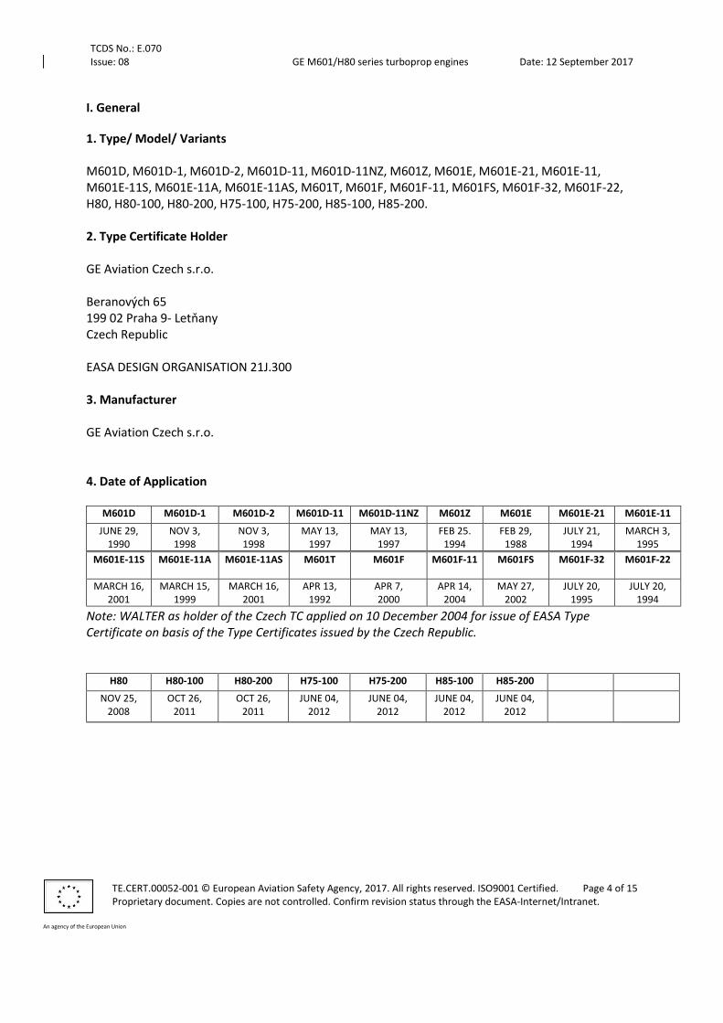
M601D, M601D-1, M601D-2, M601D-11, M601D-11NZ, M601Z, M601E, M601E-21, M601E-11, M601E-11S, M601E-11A, M601E-11AS, M601T, M601F, M601F-11, M601FS, M601F-32, M601F-22, H80, H80-100, H80-200, H75-100, H75-200, H85-100, H85-200. 2. Type Certificate Holder GE Aviation Czech s.r.o. Beranových 65 199 02 Praha 9- Letňany Czech Republic EASA DESIGN ORGANISATION 21J.300 3. Manufacturer GE Aviation Czech s.r.o. 4. Date of Application
Note: WALTER as holder of the Czech TC applied on 10 December 2004 for issue of EASA Type Certificate on basis of the Type Certificates issued by the Czech Republic.
M601D M601D-1 M601D-2 M601D-11 M601D-11NZ M601Z M601E M601E-21 M601E-11
JUNE 29, 1990
NOV 3, 1998
NOV 3, 1998
MAY 13, 1997
MAY 13, 1997
FEB 25. 1994
FEB 29, 1988
JULY 21, 1994
MARCH 3, 1995
M601E-11S M601E-11A M601E-11AS M601T M601F M601F-11 M601FS M601F-32 M601F-22
MARCH 16, 2001
MARCH 15, 1999
MARCH 16, 2001
APR 13, 1992
APR 7, 2000
APR 14, 2004
MAY 27, 2002
JULY 20, 1995
JULY 20, 1994
H80 H80-100 H80-200 H75-100 H75-200 H85-100 H85-200
NOV 25, 2008
OCT 26, 2011
OCT 26, 2011
JUNE 04, 2012
JUNE 04, 2012
JUNE 04, 2012
JUNE 04, 2012
TCDS No.: E.070 Issue: 08 GE M601/H80 series turboprop engines Date: 12 September 2017
TE.CERT.00052-001 © European Aviation Safety Agency, 2017. All rights reserved. ISO9001 Certified. Page 5 of 15 Proprietary document. Copies are not controlled. Confirm revision status through the EASA-Internet/Intranet.
An agency of the European Union
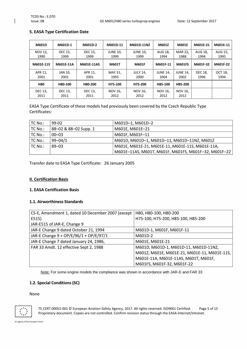
5. EASA Type Certification Date
M601D M601D-1 M601D-2 M601D-11 M601D-11NZ M601Z M601E M601E-21 M601E-11
NOV 12, 1990
DEC 15, 1999
DEC 15, 1999
JUNE 10, 1999
JUNE 10, 1999
AUG 18, 1994
MAR 22, 1988
AUG 18, 1994
AUG 15, 1995
M601E-11S M601E-11A M601E-11AS M601T M601F M601F-11 M601FS M601F-32 M601F-22
APR 11, 2001
JAN 10, 2001
APR 11, 2001
MAY 31, 1993
JULY 14, 2000
JUNE 14, 2004
JUNE 14, 2002
DEC 18, 1996
OCT 18, 1994
H80 H80-100 H80-200 H75-100 H75-200 H85-100 H85-200
DEC 13, 2011
DEC 13, 2011
DEC 13, 2011
NOV 16, 2012
NOV 16, 2012
NOV 16, 2012
NOV 16, 2012
EASA Type Certificate of these models had previously been covered by the Czech Republic Type Certificates:
TC No.: 99-02 M601D–1, M601D–2
TC No.: 88–02 & 88–02 Supp. 1 M601E, M601E–21
TC No.: 00–03 M601F, M601F–11
TC No.: 99–04/1 M601D, M601D–1, M601D–11, M601D–11NZ, M601Z
TC No.: 89–03 M601E, M601E-21, M601E-11, M601E-11S, M601E-11A, M601E–11AS, M601T, M601F, M601FS, M601F–32, M601F–22
Transfer date to EASA Type Certificate: 26 January 2005
II. Certification Basis
1. EASA Certification Basis
1.1. Airworthiness Standards
CS-E, Amendment 1, dated 10 December 2007 (except E515) JAR-E515 of JAR-E, Change 9
H80, H80-100, H80-200 H75-100, H75-200, H85-100, H85-200
JAR-E Change 9 dated October 21, 1994 M601D-1, M601F, M601F-11
JAR-E Change 9 + OP/E/96/1 + OP/E/97/1 M601D-2
JAR-E Change 7 dated January 24, 1986, M601E, M601E-21
FAR 33 Amdt. 12 effective Sept 2, 1988 M601D, M601D-1, M601D-11, M601D-11NZ, M601Z, M601E, M601E-21, M601E-11, M601E-11S, M601E-11A, M601E-11AS, M601T, M601F, M601FS, M601F-32, M601F-22
Note: For some engine models the compliance was shown in accordance with JAR-E and FAR 33
1.2. Special Conditions (SC)
None
TCDS No.: E.070 Issue: 08 GE M601/H80 series turboprop engines Date: 12 September 2017
TE.CERT.00052-001 © European Aviation Safety Agency, 2017. All rights reserved. ISO9001 Certified. Page 6 of 15 Proprietary document. Copies are not controlled. Confirm revision status through the EASA-Internet/Intranet.
An agency of the European Union
1.3. Equivalent Safety Findings (ESF)
JAR-E 570(a) and FAR 31.71 (b)(6) - Oil filter warning means indicating to the pilot impending its blockage
JAR-E 560(d) and FAR 33.67 (b) - Fuel filter
JAR-E 530(e) - Fire Precautions None for H80, H80-100, H80-200, H75-100, H75-200, H85-100, H85-200 1.4. Deviations
None
1.5. Environmental Protection Fuel Venting: CS-34.1
III. Technical Characteristics
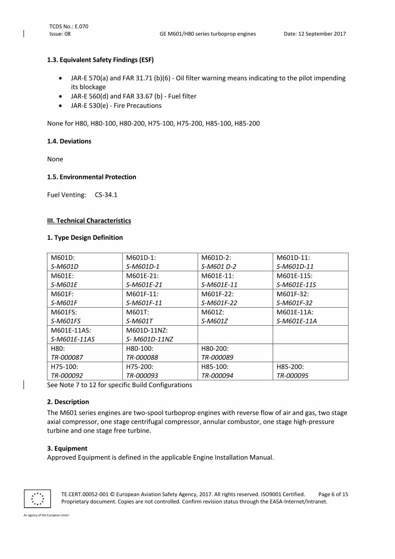
1. Type Design Definition
M601D: S-M601D
M601D-1: S-M601D-1
M601D-2: S-M601 D-2
M601D-11: S-M601D-11
M601E: S-M601E
M601E-21: S-M601E-21
M601E-11: S-M601E-11
M601E-11S: S-M601E-11S
M601F: S-M601F
M601F-11: S-M601F-11
M601F-22: S-M601F-22
M601F-32: S-M601F-32
M601FS: S-M601FS
M601T: S-M601T
M601Z: S-M601Z
M601E-11A: S-M601E-11A
M601E-11AS: S-M601E-11AS
M601D-11NZ: S- M601D-11NZ
H80: TR-000087
H80-100: TR-000088
H80-200: TR-000089
H75-100: TR-000092
H75-200: TR-000093
H85-100: TR-000094
H85-200: TR-000095
See Note 7 to 12 for specific Build Configurations
2. Description
The M601 series engines are two-spool turboprop engines with reverse flow of air and gas, two stage axial compressor, one stage centrifugal compressor, annular combustor, one stage high-pressure turbine and one stage free turbine. 3. Equipment Approved Equipment is defined in the applicable Engine Installation Manual.

TCDS No.: E.070 Issue: 08 GE M601/H80 series turboprop engines Date: 12 September 2017
TE.CERT.00052-001 © European Aviation Safety Agency, 2017. All rights reserved. ISO9001 Certified. Page 7 of 15 Proprietary document. Copies are not controlled. Confirm revision status through the EASA-Internet/Intranet.
An agency of the European Union
4. Dimensions (mm)
Overall Length 1675
Overall Width 590
Overall Height 650
5. Dry Weight (kg)
H80-100, H75-100, H85-100 200
H80, H80-200, H75-200, H85-200 202
M601D, M601D-1, M601D-2 197
M601E, M601E-21, M601E-11, M601E-11A, M601F, M601F-11, M601F-22, M601F-32, M601T
207
M601D-11, M601D-11NZ 204
M601Z 201
M601E-11S, 212
M601E-11AS, M601FS
6. Ratings (kW)
Maximum Continuous at sea level
Take-off (5 min) at sea level
Take-off with water injection (5 min) at sea level
Max. Contingency (10 min) at
sea level
Intermediate Contingency at sea level
M601D-1 490 540 - - -
M601D-2 400 450 - - -
M601E 490 560
595
560 M601E-21
M601F 500 580 580
M601F-11
M601D 490 540
M601D-11 450 -
M610D-11NZ 320 410 -
M601Z 245 382 -
M601E-11A 485 526
-
M601E-11AS -
M601T 490 560 -
M601FS 500 580 580
M601F-32 490 560
-
M601F-22 -
TCDS No.: E.070 Issue: 08 GE M601/H80 series turboprop engines Date: 12 September 2017
TE.CERT.00052-001 © European Aviation Safety Agency, 2017. All rights reserved. ISO9001 Certified. Page 8 of 15 Proprietary document. Copies are not controlled. Confirm revision status through the EASA-Internet/Intranet.
An agency of the European Union
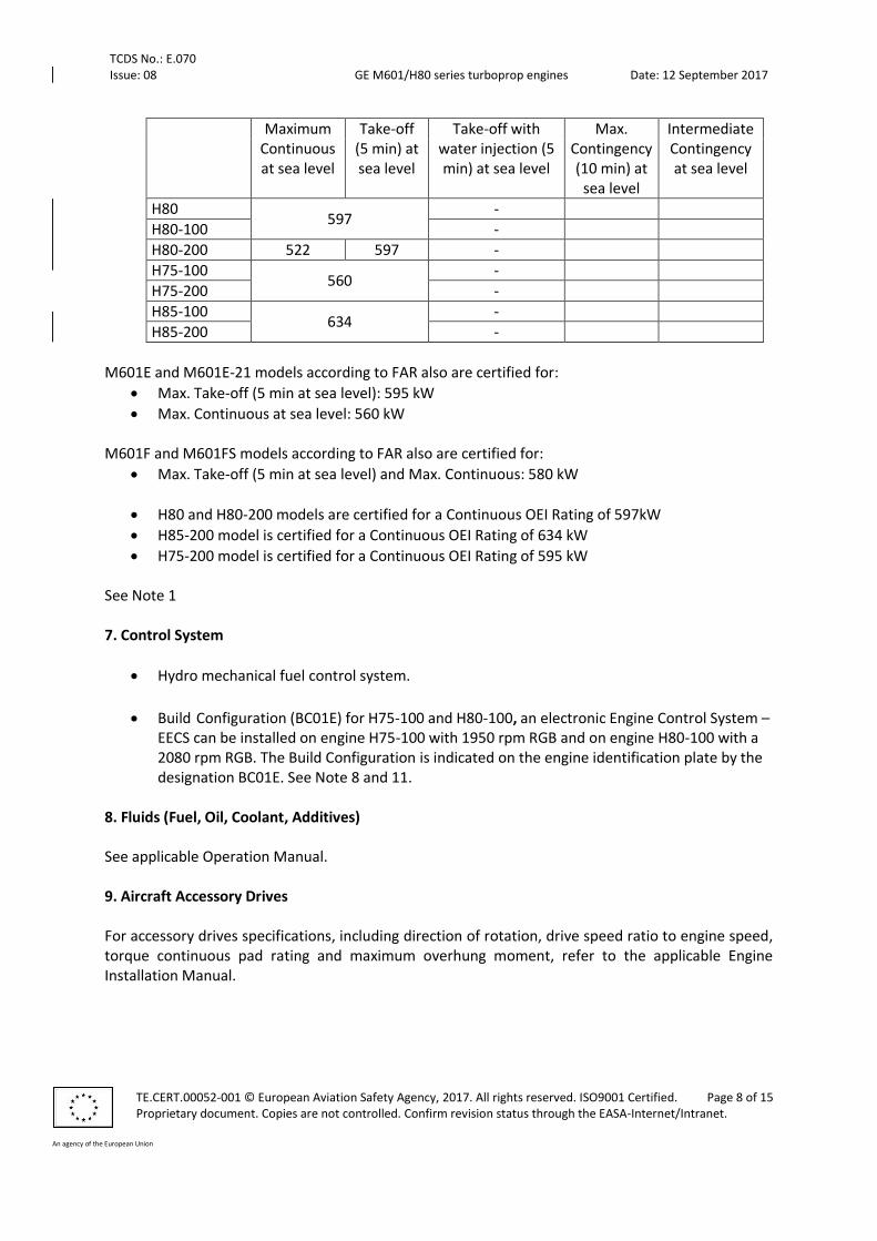
Maximum Continuous at sea level
Take-off (5 min) at sea level
Take-off with water injection (5 min) at sea level
Max. Contingency (10 min) at
sea level
Intermediate Contingency at sea level
H80 597
-
H80-100 -
H80-200 522 597 -
H75-100 560
-
H75-200 -
H85-100 634
-
H85-200 -
M601E and M601E-21 models according to FAR also are certified for:
Max. Take-off (5 min at sea level): 595 kW
Max. Continuous at sea level: 560 kW M601F and M601FS models according to FAR also are certified for:
Max. Take-off (5 min at sea level) and Max. Continuous: 580 kW
H80 and H80-200 models are certified for a Continuous OEI Rating of 597kW
H85-200 model is certified for a Continuous OEI Rating of 634 kW
H75-200 model is certified for a Continuous OEI Rating of 595 kW See Note 1 7. Control System
Hydro mechanical fuel control system.
Build Configuration (BC01E) for H75-100 and H80-100, an electronic Engine Control System – EECS can be installed on engine H75-100 with 1950 rpm RGB and on engine H80-100 with a 2080 rpm RGB. The Build Configuration is indicated on the engine identification plate by the designation BC01E. See Note 8 and 11.
8. Fluids (Fuel, Oil, Coolant, Additives) See applicable Operation Manual. 9. Aircraft Accessory Drives For accessory drives specifications, including direction of rotation, drive speed ratio to engine speed, torque continuous pad rating and maximum overhung moment, refer to the applicable Engine Installation Manual.
TCDS No.: E.070 Issue: 08 GE M601/H80 series turboprop engines Date: 12 September 2017
TE.CERT.00052-001 © European Aviation Safety Agency, 2017. All rights reserved. ISO9001 Certified. Page 9 of 15 Proprietary document. Copies are not controlled. Confirm revision status through the EASA-Internet/Intranet.
An agency of the European Union
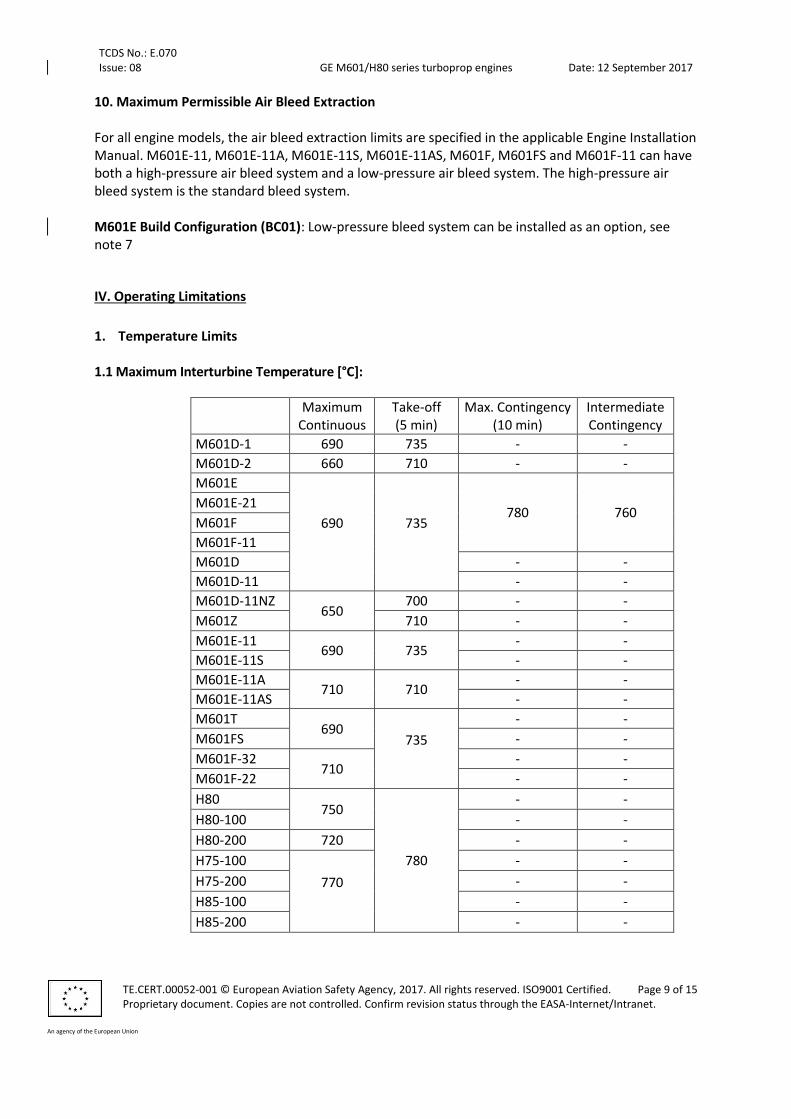
10. Maximum Permissible Air Bleed Extraction For all engine models, the air bleed extraction limits are specified in the applicable Engine Installation Manual. M601E-11, M601E-11A, M601E-11S, M601E-11AS, M601F, M601FS and M601F-11 can have both a high-pressure air bleed system and a low-pressure air bleed system. The high-pressure air bleed system is the standard bleed system. M601E Build Configuration (BC01): Low-pressure bleed system can be installed as an option, see note 7
IV. Operating Limitations
1. Temperature Limits
1.1 Maximum Interturbine Temperature [°C]:
Maximum Continuous
Take-off (5 min)
Max. Contingency (10 min)
Intermediate Contingency
M601D-1 690 735 - -
M601D-2 660 710 - -
M601E
690
735
780 760 M601E-21
M601F
M601F-11
M601D - -
M601D-11 - -
M601D-11NZ 650
700 - -
M601Z 710 - -
M601E-11 690 735
- -
M601E-11S - -
M601E-11A 710 710
- -
M601E-11AS - -
M601T 690
735
- -
M601FS - -
M601F-32 710
- -
M601F-22 - -
H80 750
780
- -
H80-100 - -
H80-200 720 - -
H75-100
770
- -
H75-200 - -
H85-100 - -
H85-200 - -

TCDS No.: E.070 Issue: 08 GE M601/H80 series turboprop engines Date: 12 September 2017
TE.CERT.00052-001 © European Aviation Safety Agency, 2017. All rights reserved. ISO9001 Certified. Page 10 of 15 Proprietary document. Copies are not controlled. Confirm revision status through the EASA-Internet/Intranet.
An agency of the European Union
Models M601E, M601E-21, M601F and M601FS have also been certified in accordance with FAR 33 for Maximum Interturbine Temperature of: 780°C at Max. Continuous
1.2 Oil Inlet Temperature Range [°C]:
Maximum: 85 Minimum: -20
1.3 Fuel Inlet Temperature Range [°C]:
Maximum: 60 Minimum: -50
2. Speed Limits
2.1 Maximum Permissible Rotor Speeds:
Rating Engine Model Gas Generator
Rotor [%]
Propeller Shaft [min-1]
Take-off M601D, M601D-1 101,5 2080
M601D-2, M601D-11NZ 99 1950
M601D-11
100 M601E, M601E-11, M601E-21, M601E-11S, M601F, M601FS, M601F-11, M601F-22, M601F-32, M601T
2080
M601Z 99 1900
M601E-11A, M601E-11AS 98,5 2080
H80, H80-100, H80-200
101,5 H75-100, H75-200, H85-100
H85-200 1950
Max. Continuous M601D, M601D-1 99 2080
M601D-2 96 1950
M601D-11 98,5
M601E, M601E-11, M601E-11S,
M601E-21, M601F, M601FS, M601F-11,
M601F-22, M601F-32, M601T
97 2080
M601E-11A, M601E-11AS 98,5
M601D-11NZ 95 1950
M601Z 94 1800
H80, H80-100 100,1
2080 H80-200 98,4
H75-100, H75-200 101,1
H85-100 101,2
H85-200 1950
Max. Contingency (10 min)
M601E, M601E-21, M601F, M601F-11, M601FS
102
2080 Intermediate Contingency
M601E, M601E-21, M601F, M601F-11, M601FS
100.5
TCDS No.: E.070 Issue: 08 GE M601/H80 series turboprop engines Date: 12 September 2017
TE.CERT.00052-001 © European Aviation Safety Agency, 2017. All rights reserved. ISO9001 Certified. Page 11 of 15 Proprietary document. Copies are not controlled. Confirm revision status through the EASA-Internet/Intranet.
An agency of the European Union
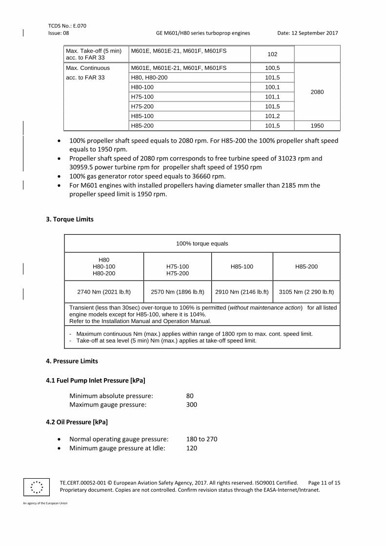
Max. Take-off (5 min) acc. to FAR 33
M601E, M601E-21, M601F, M601FS 102
Max. Continuous M601E, M601E-21, M601F, M601FS 100,5
2080
acc. to FAR 33 H80, H80-200 101,5
H80-100 100,1
H75-100 101,1
H75-200 101,5
H85-100 101,2
H85-200 101,5 1950
100% propeller shaft speed equals to 2080 rpm. For H85-200 the 100% propeller shaft speed equals to 1950 rpm.
Propeller shaft speed of 2080 rpm corresponds to free turbine speed of 31023 rpm and 30959.5 power turbine rpm for propeller shaft speed of 1950 rpm
100% gas generator rotor speed equals to 36660 rpm.
For M601 engines with installed propellers having diameter smaller than 2185 mm the propeller speed limit is 1950 rpm.
3. Torque Limits
100% torque equals
H80 H80-100 H80-200
H75-100 H75-200
H85-100 H85-200
2740 Nm (2021 lb.ft) 2570 Nm (1896 lb.ft) 2910 Nm (2146 lb.ft) 3105 Nm (2 290 lb.ft)
Transient (less than 30sec) over-torque to 106% is permitted (without maintenance action) for all listed engine models except for H85-100, where it is 104%. Refer to the Installation Manual and Operation Manual.
- Maximum continuous Nm (max.) applies within range of 1800 rpm to max. cont. speed limit. - Take-off at sea level (5 min) Nm (max.) applies at take-off speed limit.
4. Pressure Limits
4.1 Fuel Pump Inlet Pressure [kPa]
Minimum absolute pressure: 80 Maximum gauge pressure: 300
4.2 Oil Pressure [kPa]
Normal operating gauge pressure: 180 to 270
Minimum gauge pressure at Idle: 120
TCDS No.: E.070 Issue: 08 GE M601/H80 series turboprop engines Date: 12 September 2017
TE.CERT.00052-001 © European Aviation Safety Agency, 2017. All rights reserved. ISO9001 Certified. Page 12 of 15 Proprietary document. Copies are not controlled. Confirm revision status through the EASA-Internet/Intranet.
An agency of the European Union
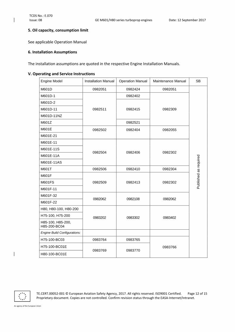
5. Oil capacity, consumption limit
See applicable Operation Manual
6. Installation Assumptions
The installation assumptions are quoted in the respective Engine Installation Manuals.
V. Operating and Service Instructions
Engine Model Installation Manual Operation Manual Maintenance Manual SB
M601D 0982051 0982424 0982051
Pu
blis
hed
as r
equ
ire
d
M601D-1
0982511
0982402
0982309
M601D-2
0982415 M601D-11
M601D-11NZ
M601Z 0982521
M601E 0982502
0982404
0982055
M601E-21
M601E-11
0982504 0982406 0982302 M601E-11S
M601E-11A
M601E-11AS
M601T 0982506 0982410 0982304
M601F
0982509 0982413 0982302 M601FS
M601F-11
M601F-32 0982062 0982108 0982062
M601F-22
H80, H80-100, H80-200
0983202 0983302 0983402 H75-100, H75-200
H85-100, H85-200, H85-200-BC04
Engine Build Configurations:
H75-100-BC03 0983764 0983765
0983766 H75-100-BC01E 0983769 0983770
H80-100-BC01E
TCDS No.: E.070 Issue: 08 GE M601/H80 series turboprop engines Date: 12 September 2017
TE.CERT.00052-001 © European Aviation Safety Agency, 2017. All rights reserved. ISO9001 Certified. Page 13 of 15 Proprietary document. Copies are not controlled. Confirm revision status through the EASA-Internet/Intranet.
An agency of the European Union
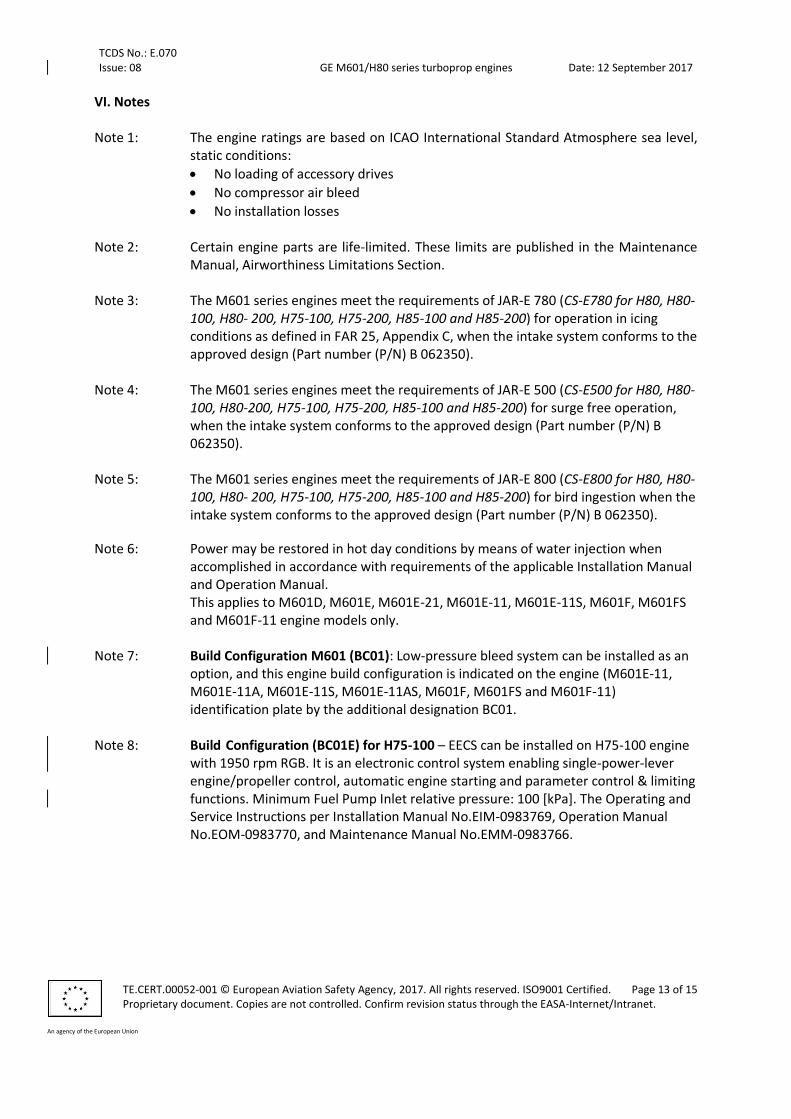
VI. Notes Note 1: The engine ratings are based on ICAO International Standard Atmosphere sea level,
static conditions:
No loading of accessory drives
No compressor air bleed
No installation losses Note 2: Certain engine parts are life-limited. These limits are published in the Maintenance
Manual, Airworthiness Limitations Section. Note 3: The M601 series engines meet the requirements of JAR-E 780 (CS-E780 for H80, H80-
100, H80- 200, H75-100, H75-200, H85-100 and H85-200) for operation in icing conditions as defined in FAR 25, Appendix C, when the intake system conforms to the approved design (Part number (P/N) B 062350).
Note 4: The M601 series engines meet the requirements of JAR-E 500 (CS-E500 for H80, H80-
100, H80-200, H75-100, H75-200, H85-100 and H85-200) for surge free operation, when the intake system conforms to the approved design (Part number (P/N) B 062350).
Note 5: The M601 series engines meet the requirements of JAR-E 800 (CS-E800 for H80, H80-
100, H80- 200, H75-100, H75-200, H85-100 and H85-200) for bird ingestion when the intake system conforms to the approved design (Part number (P/N) B 062350).
Note 6: Power may be restored in hot day conditions by means of water injection when accomplished in accordance with requirements of the applicable Installation Manual and Operation Manual. This applies to M601D, M601E, M601E-21, M601E-11, M601E-11S, M601F, M601FS and M601F-11 engine models only.
Note 7: Build Configuration M601 (BC01): Low-pressure bleed system can be installed as an
option, and this engine build configuration is indicated on the engine (M601E-11, M601E-11A, M601E-11S, M601E-11AS, M601F, M601FS and M601F-11) identification plate by the additional designation BC01.
Note 8: Build Configuration (BC01E) for H75-100 – EECS can be installed on H75-100 engine
with 1950 rpm RGB. It is an electronic control system enabling single-power-lever engine/propeller control, automatic engine starting and parameter control & limiting functions. Minimum Fuel Pump Inlet relative pressure: 100 [kPa]. The Operating and Service Instructions per Installation Manual No.EIM-0983769, Operation Manual No.EOM-0983770, and Maintenance Manual No.EMM-0983766.
TCDS No.: E.070 Issue: 08 GE M601/H80 series turboprop engines Date: 12 September 2017
TE.CERT.00052-001 © European Aviation Safety Agency, 2017. All rights reserved. ISO9001 Certified. Page 14 of 15 Proprietary document. Copies are not controlled. Confirm revision status through the EASA-Internet/Intranet.
An agency of the European Union
Note 9 Build Configuration (BC02) for M601 - Engines with 4000 flight cycles. Number of equivalent flight cycles within TBO is extended up 4000 while hourly TBO limit is observed for the following engine models with the additional designation BC02 on the engine plate: M601D, M601E, M601E-11.
Note 10: Build Configuration (BC03) for H75-100 - Low rpm speed reduction gearbox can be
installed as an option on H75-100 and this engine build configuration is indicated on the engine identification plate by the additional designation BC03. The engine ratings and operational limits, dimensions, weight unchanged while the max permissible Propeller Shaft speed 1900 rpm and torque limitation 2815 Nm (2076 lb.ft). The Operating and Service Instructions per Installation Manual No. 0983764, Operation Manual No. 0983765, and Maintenance Manual No. 0983766
Note 11: Build Configuration (BC01E) for H80-100 – EECS can be installed on H80-100 engine
with 2080 rpm RGB. The Build Configuration is indicated on the engine identification plate by the designation BC01E. It is an electronic control system enabling single-power-lever engine/propeller control, automatic engine starting and parameter control & limiting functions. Minimum Fuel Pump Inlet relative pressure: 100 [kPa]. The Operating and Service Instructions per Installation Manual No.EIM-0983769, Operation Manual No.EOM-0983770, and Maintenance Manual No.EMM-0983766.
Note 12: Build Configuration (BC04) for H85-200 - Reduction gearbox with 1950 rpm is
installed on H85-200 and this engine build configuration is indicated on the engine identification plate by the additional designation BC04. The engine ratings and operational limits, dimensions, weight unchanged while the max permissible Propeller Shaft speed 1950 rpm and torque limitation 3105 Nm (2290 lb.ft). The Operating and Service Instructions per Installation Manual No. 0983202, Operation Manual No. 0983302, and Maintenance Manual No. 0983402. This engine build configuration replaces the previous H85-200 engine model baseline.
TCDS No.: E.070 Issue: 08 GE M601/H80 series turboprop engines Date: 12 September 2017
TE.CERT.00052-001 © European Aviation Safety Agency, 2017. All rights reserved. ISO9001 Certified. Page 15 of 15 Proprietary document. Copies are not controlled. Confirm revision status through the EASA-Internet/Intranet.
An agency of the European Union
SECTION: ADMINISTRATIVE
I. Acronyms and Abbreviations
BC Build Configuration
CS-E Certification Specifications for engines
FAR 33 Federal Aviation Regulation – Part 33 – Airworthiness standards: Aircraft engines
ICAO International Civil Aviation Organization
JAR-E Joint Aviation Requirements – Engines
OEI One Engine Inoperative
P/N Part Number
TBO Time Between Overhauls
SB Service Bulletin
II. Type Certificate Holder Record
None
III. Change Record
Issue Date Changes TC issue
Issue 01 26 January 2005
Initial Issue - Transfer to EASA Type Certificate Initial Issue, 26 January 2005
Issue 02 26 April 2005 Change of TC Holder from Walter to Walter Engines a.s. 26 April 2005
Issue 03 25 August 2008 New TC Holder GE Aviation Czech 25 August 2008
Issue 04 13 December 2011
added H80, H80-100 and H80-200 engine models 13 December 2011
Issue 05 16 November 2012
added H75-100, H75-200, H85-100 and H85-200 engine models
16 November 2012
Issue 06 05 September 2016
Torque limits, BC03 added – new formatting
Issue 07 30 November 2016
Build Configuration BC01E added as per Major Change M601H-NZ 300, implementation of Engine Electronic Control Unit. Approval No. 10060218
Issue 08 12 September 2017
Implementation of Build Configuration BC01E for H80-100 engine model added as per Major Change DCP- 01450, implementation of Engine Electronic Control Unit. Approval No. 10062865. Implementation of Build Configuration BC04 for H85-200 engine model added as Major Change NZ-3123 introducing a propeller reduction gearbox with shaft speed to 1950 rpm. Approval No. 10063105.
-END-