type co overcurrent relay class 1e application … · 41-100.1c co overcurrent relay, class 1e 2...
TRANSCRIPT
Instruction Leaflet
All possible contingencies which may arise during installation, operation or maintenance, and all details andvariations of this equipment do not purport to be covered by these instructions. If further information isdesired by purchaser regarding this particular installation, operation or maintenance of this equipment, thelocal ABB representative should be contacted.
ABB 41-100.1C
( ) Denotes Change Since Previous Issue
CONTENTS
This instruction leaflet applies to the followingtypes of relays:
Type CO-2 Short Time RelayType CO-5 Long Time RelayType CO-6 Definite Minimum Time RelayType CO-7 Moderately Inverse Time RelayType CO-8 Inverse Time RelayType CO-9 Very Inverse Time RelayType CO-11 Extremely Inverse Relay
CAUTION!Before putting relays into service, remove allblocking which may have been inserted for thepurpose of securing the parts during shipment,make sure that all moving parts operate freely,inspect the contacts to see that they are cleanand close properly, and operate the relay tocheck the settings and electrical connections.
1.0 APPLICATION
These relays have been specially designed andtested to establish their suitability for Class 1E appli-cations in accordance with the ABB Relay Divisionprogram for Class 1E Qualification Testing asdetailed in the ABB bulletin STR-1.
“Class 1E” is the safety classification of the electricequipment and systems in nuclear power generatingstations that are essential to emergency shutdown of
the reactor, containment isolation, cooling of thereactor, and heat removal from the containment andreactor, or otherwise are essential in preventing sig-nificant release of radioactive material to the environ-ment.
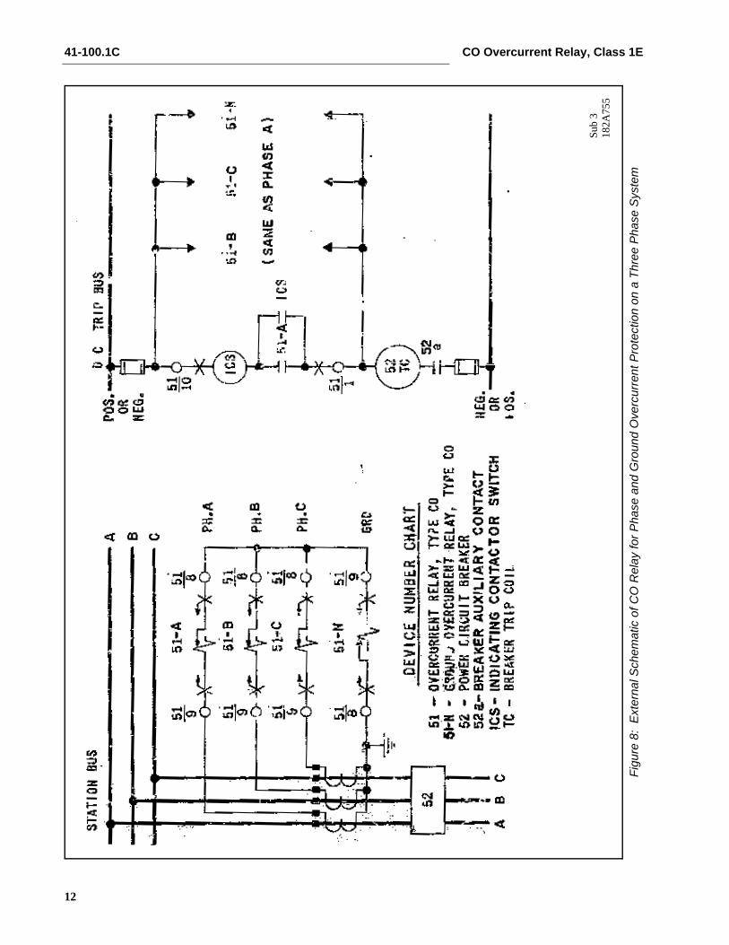
These induction overcurrent relays are used to dis-connect circuits or apparatus when the current inthem exceeds a given value. Where a station battery(48 volts or over) is available, the circuit closing typerelays are normally used to trip the circuit breaker.
2.0 CONSTRUCTION AND OPERATION
The Type CO relays consists of an overcurrent unit(CO), an indicating contactor switch (ICS), and anindicating instantaneous trip unit (IIT) when required.
2.1 ELECTROMAGNET
The electromagnets for the Types CO-5, CO-6, CO-7, CO-8 and CO-9 relays have a main tapped coillocated on the center leg of an “E” type laminatedstructure that produces a flux which divides andreturns through the outer legs. A shading coil causesthe flux through the left leg to lag the main pole flux.The out-of-phase fluxes thus produced in the air gapcause a contact closing torque. A torque controlledCO has the lag coil connections of the electromagnetbrought out to separate terminals. This permits con-trol of the closing torque such that only when theseterminals are connected together will the unit oper-ate.
Effective: May 2009
Supersedes I.L. 41-100.1B, Dated November 1999
Type COOvercurrent RelayClass 1E Application
41-100.1C CO Overcurrent Relay, Class 1E
2
The electromagnets for the Types CO-2 and CO-11relays have a main coil consisting of a tapped pri-mary winding and a secondary winding. Two identi-cal coils on the outer legs of the lamination structureare connected to the main coil secondary in a man-ner so that the combination of all the fluxes producedby the electromagnet result in out-of-phase fluxes inthe air gap. The out-of-phase air gap fluxes producedcause a contact closing torque.
2.2 INDICATING CONTACTOR SWITCH UNIT (ICS)
The dc indicating contactor switch is a small clappertype device. A magnetic armature, to which leaf-spring mounted contacts are attached, is attracted tothe magnetic core upon energization of the switch.When the switch closes, the moving contacts bridgetwo stationary contacts, completing the trip circuit.For double circuit closing contacts, the moving con-tacts bridge three stationary contacts. Also duringthis operation two fingers on the armature deflect aspring located on the front of the switch, which allowsthe operation indicator target to drop.
The front spring, in addition to holding the target, pro-vides restraint for the armature and thus controls thepickup value of the switch.
2.3 INDICATING INSTANTANEOUS TRIP UNIT (IIT)
The instantaneous trip unit is a small ac operatedclapper type device. A magnetic armature, to whichleaf-spring mounted contacts are attached, isattracted to the magnetic core upon energization ofthe switch. When the switch closes, the moving con-tacts bridge two stationary contacts completing thetrip circuit. For double circuit closing contacts, themoving contacts bridge three stationary contacts.Also, during the operation, two fingers on the arma-ture deflect a spring located on the front of the switchwhich allows the operation indictor target to drop.
A core screw accessible from the top of the switchand taps on the coil provides the adjustable pickuprange.
3.0 CHARACTERISTIC
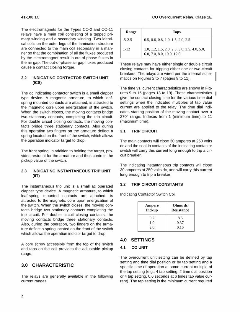
The relays are generally available in the followingcurrent ranges:
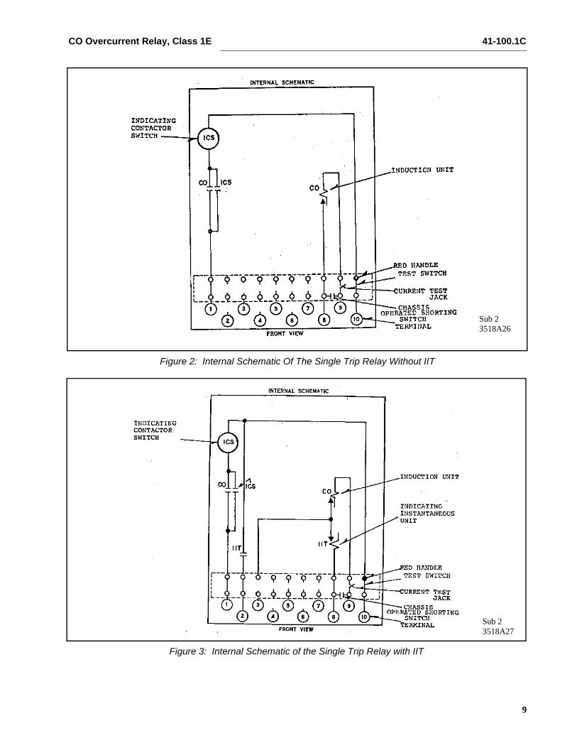
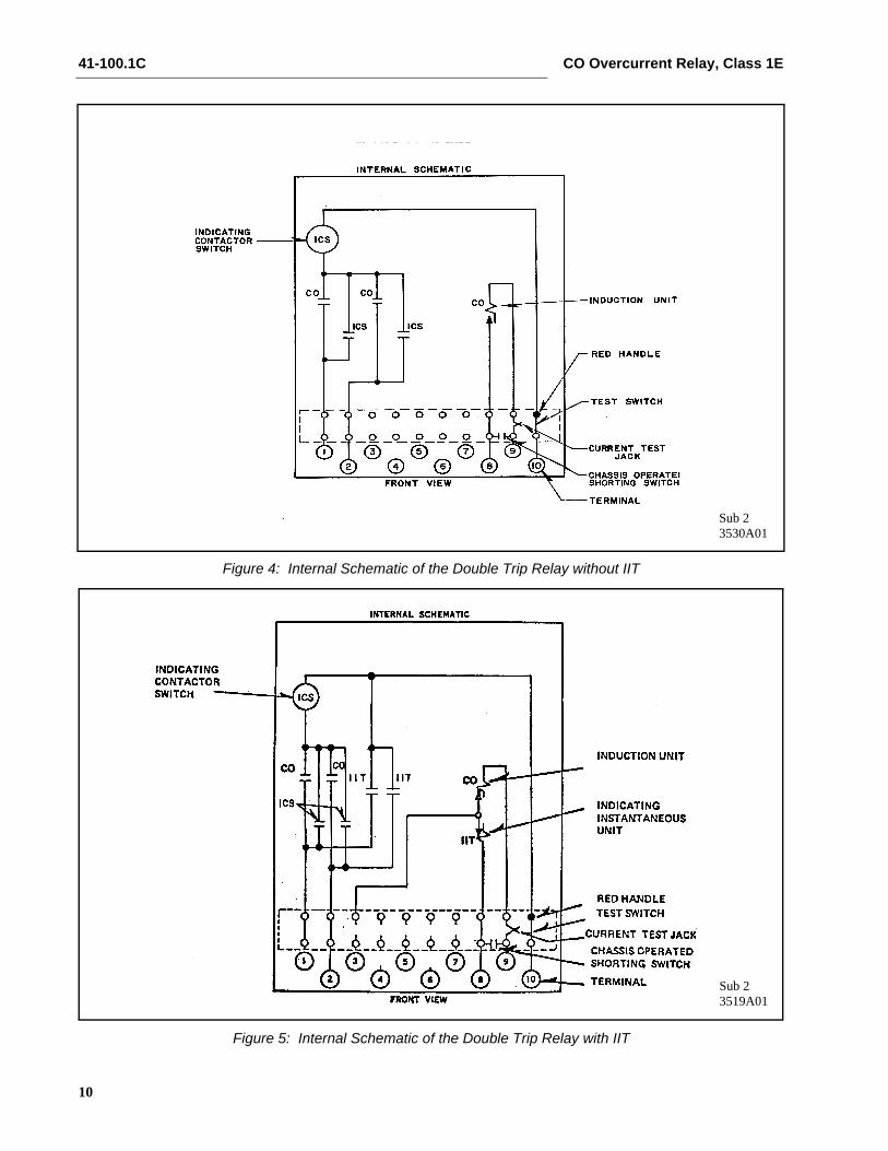
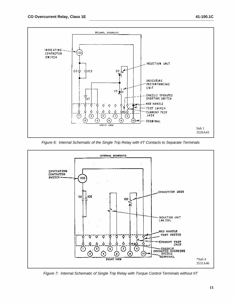
These relays may have either single or double circuitclosing contacts for tripping either one or two circuitbreakers. The relays are wired per the internal sche-matics on Figures 2 to 7 (pages 9 to 11).
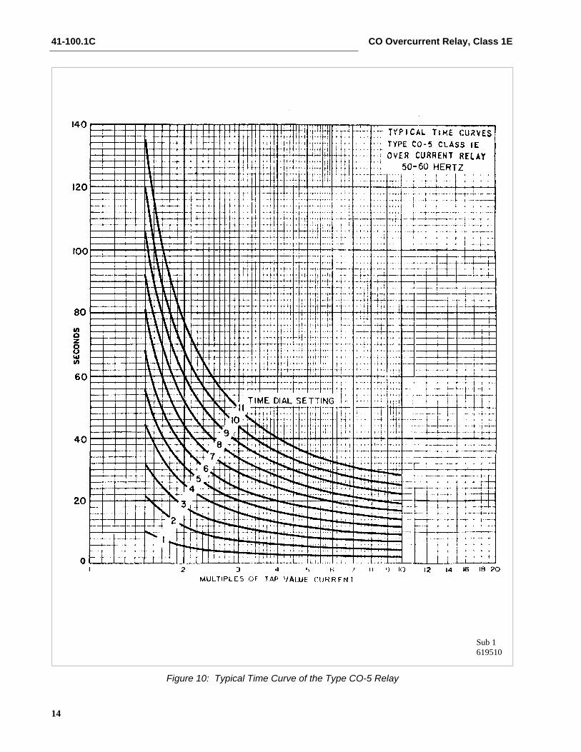
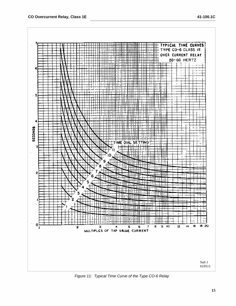
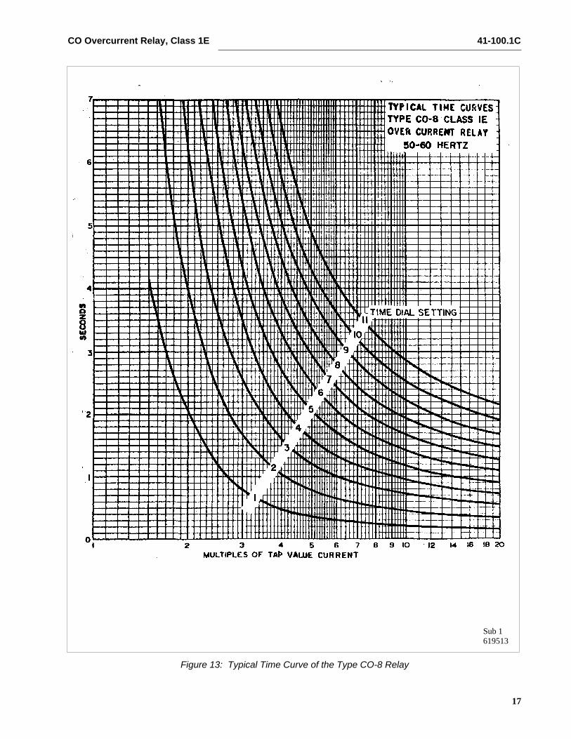
The time vs. current characteristics are shown in Fig-ures 9 to 15 (pages 13 to 19). These characteristicsgive the contact closing time for the various time dialsettings when the indicated multiples of tap valuecurrent are applied to the relay. The time dial indi-cates starting position of the moving contact over a270° range. Indexes from 1 (minimum time) to 11(maximum time).
3.1 TRIP CIRCUIT
The main contacts will close 30 amperes at 250 voltsdc and the seal-in contacts of the indicating contactorswitch will carry this current long enough to trip a cir-cuit breaker.
The indicating instantaneous trip contacts will close30 amperes at 250 volts dc, and will carry this currentlong enough to trip a breaker.
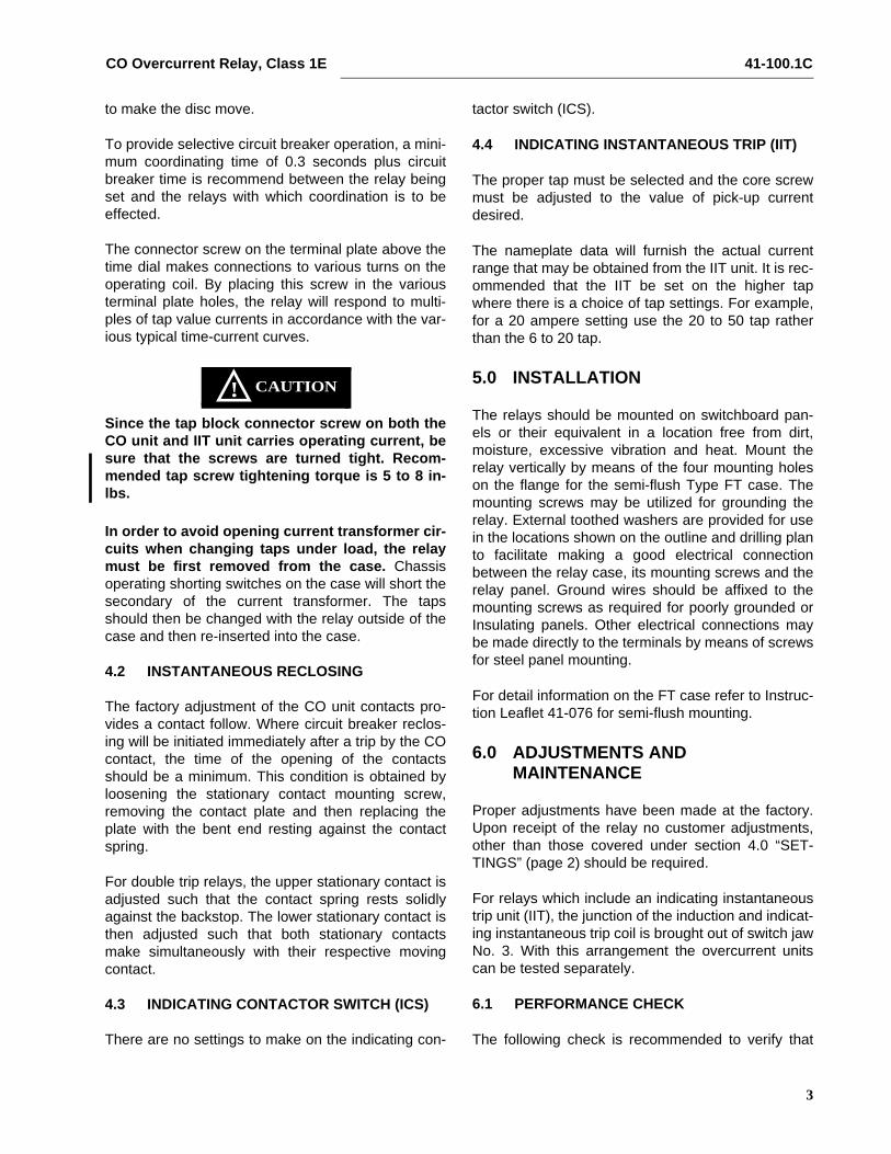
3.2 TRIP CIRCUIT CONSTANTS
Indicating Contactor Switch Coil
4.0 SETTINGS4.1 CO UNIT
The overcurrent unit setting can be defined by tapsetting and time dial position or by tap setting and aspecific time of operation at some current multiple ofthe tap setting (e.g., 4 tap setting, 2 time dial positionor 4 tap setting, 0.6 seconds at 6 times tap value cur-rent). The tap setting is the minimum current required
Range Taps
.5-2.5
1-12
0.5, 0.6, 0.8, 1.0, 1.5, 2.0, 2.5
1.0, 1.2, 1.5, 2.0, 2.5, 3.0, 3.5, 4.0, 5.0, 6.0, 7.0, 8.0, 10.0, 12.0
Ampere Pickup
Ohms dc Resistance
0.21.02.0
8.50.370.10
CO Overcurrent Relay, Class 1E 41-100.1C
3
to make the disc move.
To provide selective circuit breaker operation, a mini-mum coordinating time of 0.3 seconds plus circuitbreaker time is recommend between the relay beingset and the relays with which coordination is to beeffected.
The connector screw on the terminal plate above thetime dial makes connections to various turns on theoperating coil. By placing this screw in the variousterminal plate holes, the relay will respond to multi-ples of tap value currents in accordance with the var-ious typical time-current curves.
CAUTION!Since the tap block connector screw on both theCO unit and IIT unit carries operating current, besure that the screws are turned tight. Recom-mended tap screw tightening torque is 5 to 8 in-lbs.
In order to avoid opening current transformer cir-cuits when changing taps under load, the relaymust be first removed from the case. Chassisoperating shorting switches on the case will short thesecondary of the current transformer. The tapsshould then be changed with the relay outside of thecase and then re-inserted into the case.
4.2 INSTANTANEOUS RECLOSING
The factory adjustment of the CO unit contacts pro-vides a contact follow. Where circuit breaker reclos-ing will be initiated immediately after a trip by the COcontact, the time of the opening of the contactsshould be a minimum. This condition is obtained byloosening the stationary contact mounting screw,removing the contact plate and then replacing theplate with the bent end resting against the contactspring.
For double trip relays, the upper stationary contact isadjusted such that the contact spring rests solidlyagainst the backstop. The lower stationary contact isthen adjusted such that both stationary contactsmake simultaneously with their respective movingcontact.
4.3 INDICATING CONTACTOR SWITCH (ICS)
There are no settings to make on the indicating con-
tactor switch (ICS).
4.4 INDICATING INSTANTANEOUS TRIP (IIT)
The proper tap must be selected and the core screwmust be adjusted to the value of pick-up currentdesired.
The nameplate data will furnish the actual currentrange that may be obtained from the IIT unit. It is rec-ommended that the IIT be set on the higher tapwhere there is a choice of tap settings. For example,for a 20 ampere setting use the 20 to 50 tap ratherthan the 6 to 20 tap.
5.0 INSTALLATION
The relays should be mounted on switchboard pan-els or their equivalent in a location free from dirt,moisture, excessive vibration and heat. Mount therelay vertically by means of the four mounting holeson the flange for the semi-flush Type FT case. Themounting screws may be utilized for grounding therelay. External toothed washers are provided for usein the locations shown on the outline and drilling planto facilitate making a good electrical connectionbetween the relay case, its mounting screws and therelay panel. Ground wires should be affixed to themounting screws as required for poorly grounded orInsulating panels. Other electrical connections maybe made directly to the terminals by means of screwsfor steel panel mounting.
For detail information on the FT case refer to Instruc-tion Leaflet 41-076 for semi-flush mounting.
6.0 ADJUSTMENTS AND MAINTENANCE
Proper adjustments have been made at the factory.Upon receipt of the relay no customer adjustments,other than those covered under section 4.0 “SET-TINGS” (page 2) should be required.
For relays which include an indicating instantaneoustrip unit (IIT), the junction of the induction and indicat-ing instantaneous trip coil is brought out of switch jawNo. 3. With this arrangement the overcurrent unitscan be tested separately.
6.1 PERFORMANCE CHECK
The following check is recommended to verify that
41-100.1C CO Overcurrent Relay, Class 1E
4
the relay is in proper working order.
6.1.1 CO UNIT
Contact
The index mark on the movement frame will coincidewith the “0” mark on the time dial when the stationarycontact has moved through approximately one-half ofits normal deflection. Therefore, with the stationarycontact resting against the backstop, the index markis offset to the right of the “0” mark by approximately.020”. The placement of the various time dial posi-tions in line with the index mark will give operatingtimes as shown on the respective current curves.
Settings – Overcurrent Unit
The 0.5 - 2.5 ampere range CO Relay should be seton the lowest tap for these tests. The 1 to 12 amp.range CO relay should be set on the 2 amp tap withthe exception of the 1 - 12 ampere range CO-2 whichshould be set on the 1 ampere tap.
Minimum Trip Current
Set the time dial to position 6 using the lowest tapsetting, alternately apply tap value current plus 3%and tap value current minus 3%. The moving contactshould leave the backstop at tap value current plus3% and should return to the backstop at tap valuecurrent minus 3%.
time Curve
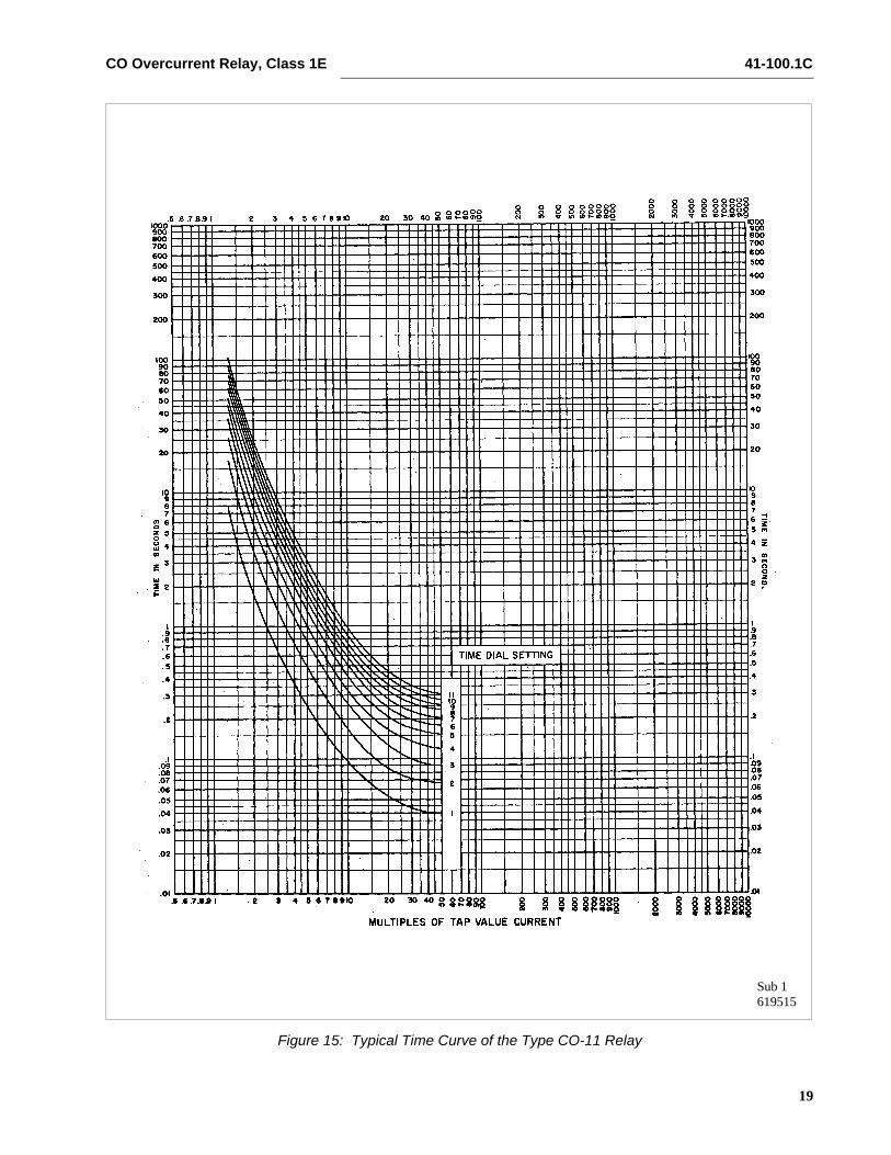
For Type CO-11 relay only, the 1.30 times tap valueoperating time from the number 6 time dial position is54.9 ±5% seconds and should be checked first. It isimportant that the 1.30 times tap value current bemaintained accurately. The maintaining of this cur-rent accurately is necessary because of the steep-ness of the slope of the time-current characteristic(Figure 15). A slight variation, ±1%, in the 1.3 timestap value current (including measuring instrumentdeviation) will change the timing tolerance to ±10% ofthe effects of different taps can make the total varia-tions appear to be ±15%.
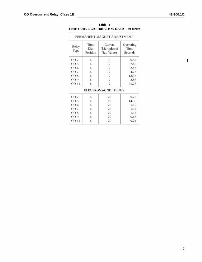
Table 1 (page 7) shows the time curve calibrationpoints for the various types of relays. With the timedial set to the indicated position apply the currentsspecified by Table 1, (e.g. for the CO-8, 2 and 20times tap value current) and measure the operatingtime of the relay.
The operating times should equal those of Table 1plus or minus 5%.
6.1.2 INDICATING INSTANTANEOUS TRIP UNIT (IIT)
The core screw which is adjustable from the top ofthe trip unit and the tap located on the top of the IITdetermines the pickup value. The trip unit has a nom-inal ratio of adjustment of 1 to 24.
Apply sufficient current to operate the IIT. The opera-tion indicator target should drop freely.
6.1.3 INDICATING CONTACTOR SWITCH (ICS)
Close the main relay contacts and pass sufficient dccurrent through the trip circuit to close the contacts ofthe ICS. This value of current should not be greaterthan the particular ICS nameplate rating. The indica-tor target should drop freely.
Repeat above except pass 85% of ICS nameplaterating current. Contacts should not pickup the targetshould not drop.
7.0 ROUTINE MAINTENANCE
All relays should be inspected periodically. Theyshould receive a “Performance Check” at least onceevery year or at such other time intervals as may bedictated by experience to be suitable to the particularapplication. A minimum suggested check on therelay system is to close the contacts manually so thatthe breaker trips and the target drops. Then releasethe contacts and observe that the reset is smoothand positive.
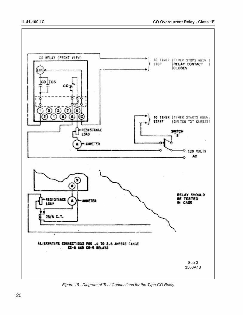
If an additional time check is desired, pass test cur-rent through the relay and check the time of opera-tion. It is preferable to make this at several timespick-up current at an expected operating point for theparticular application. For the 0.5 to 2.5 ampererange CO-5 and CO-6 induction unit use the alterna-tive test circuit in Figure 16 (page 20) as these relaysare affected by a distorted waveform. With this con-nection the 25/5 ampere current transformers shouldbe worked well below the knee of the saturation (i.e.,use 10L50 or better).
All contacts should be checked and cleaned if neces-sary. A contact burnisher No. 182A836H01 is recom-mended for this purpose. The use of abrasive

CO Overcurrent Relay, Class 1E 41-100.1C
5
material for cleaning contacts is not recommended,because of the danger of embedding small particlesin the face of the soft silver and thus impairing thecontact.
8.0 CALIBRATION
Use the following procedure for calibrating the relay ifthe relay has been taken apart for repairs or theadjustments disturbed. This procedure should not beused until it is apparent that the relay is not in properworking order. (See “Performance Check”, page 3.)
NOTE: A spring shield covers the reset spring ofthe CO relay. To remove the spring shield,requires that the damping magnet be removedfirst. The screw connection holding the lead tothe moving contact should be removed next. Thesecond screw holding the moving contactassembly should than be loosened but notremoved. (CAUTION: This screw terminates intoa nut held captive beneath the molded block. Ifscrew is removed, difficulty will be experiencedin the re-assembly of the moving contact assem-bly.) Slide the spring shield outward and removefrom relay. Tighten the screw holding the movingcontact assembly to the molded block.
8.1 CO UNIT
Contact
The index mark on the movement frame will coincidewith the “0” mark on the time dial when the stationarycontact has moved through approximately one-half ofits normal deflection. Therefore, with the stationarycontact resting against the backstop, the index markis offset to the right of the “0” mark by approximately.020”. The placement of the various time dial posi-tions in line with the index mark will give operatingtimes as shown on the respective timecurrent curves.
Setting – Overcurrent Unit
To minimize timing errors due to such factors as dif-ferent taps and self heating of CO coil, the followingtaps are recommended in the calibration of the vari-ous CO relays.
Set the 0.5 to 2.5 range CO relay on the minimumtap setting. Set the 1 - 12 ampere range CO relay onthe 2 amp tap with the exception of the 1 - 12 ampererange CO-2 relay which should be set on the 1ampere tap.
Minimum Trip Current
The adjustment of the spring tension in setting theminimum trip current value of the relay is most con-veniently made with the damping magnet removed.
With the time dial set on “0”, wind up the spiral springby means of the spring adjuster until approximately6-3/4 convolutions show.
The spiral spring can be adjusted with the springshield in place as follows. One slot of the springadjuster will be available for a screwdriver in one win-dow of the front barrier of the spring shield. Byadjusting this slot until a barrier of the spring shieldprevents further adjustment, a second slot of thespring adjustment will appear in the window on theother side of the spring shield barrier. Adjusting thesecond slot in a similar manner will reveal a third slotin the opposite window of the spring shield.
Adjust the control spring tension so that the movingcontact will leave the backstop at tap value current+1.0% and will return to the backstop at tap valuecurrent -1.0%.
Time Curve Calibration
Install the permanent magnet. Apply the indicatedcurrent per Table 1 for permanent magnet adjust-ment (e.g. CO-8, 2 times tap value) and measure theoperating time. Adjust the permanent magnet keeperuntil the operating time corresponds to the value ofTable 1.
For Type CO-11 relay only, the 1.30 times tap valueoperating time from the number 6 time dial position is54.9 ±5% seconds. It is important that the 1.30 timestap value current be maintained accurately. Themaintaining of this current accurately is necessarybecause of the steepness of the slope of the time-current characteristic (Figure 15). A slight variation,±1%, in the 1.3 times tap value current (includingmeasuring instrument deviation) will change the tim-ing tolerance to ±10% and the effect of different tapscan make the total variations appear to be ±15%. Ifthe operating time at 0.13 times tap value is notwithin these limits, a minor adjustment of the controlspring will give the correct operating time without anyundue effect on the minimum pick-up of the relay.This check is to be made after the 2 times tap valueadjustment has been made.
41-100.1C CO Overcurrent Relay, Class 1E
6
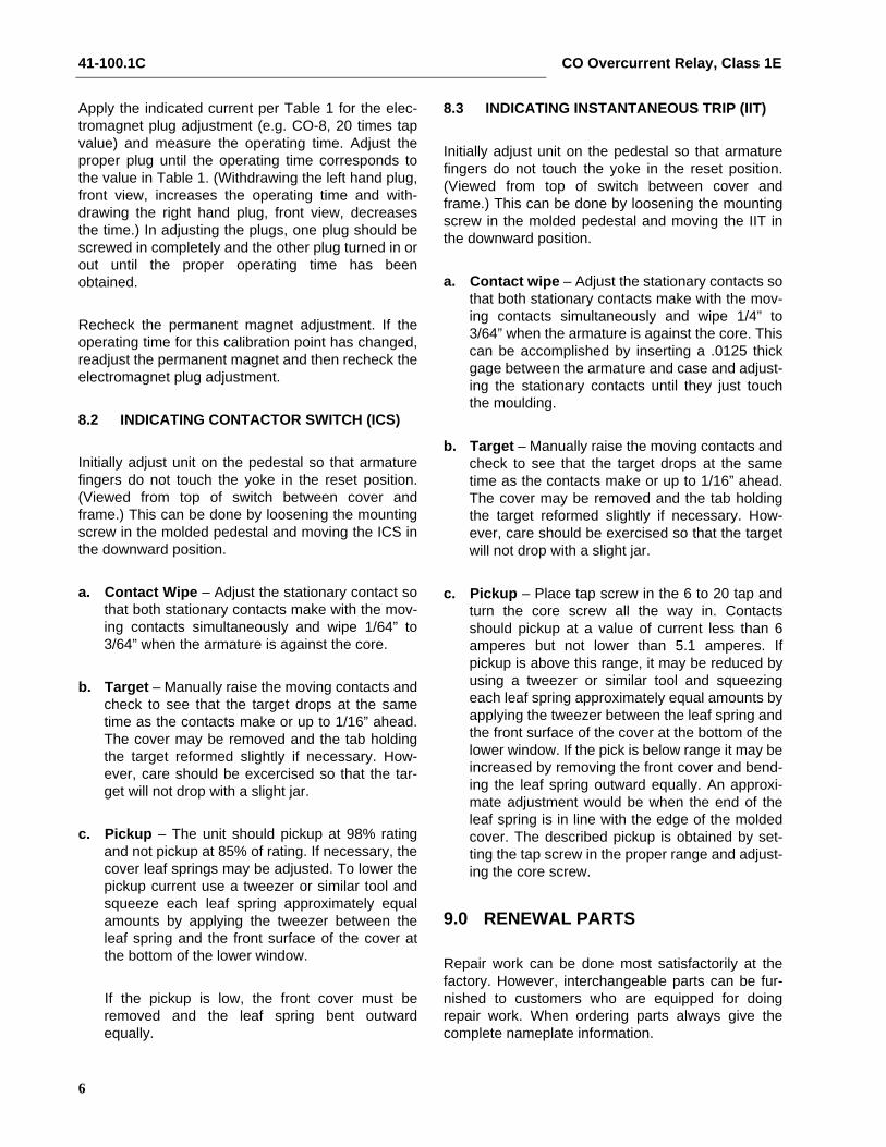
Apply the indicated current per Table 1 for the elec-tromagnet plug adjustment (e.g. CO-8, 20 times tapvalue) and measure the operating time. Adjust theproper plug until the operating time corresponds tothe value in Table 1. (Withdrawing the left hand plug,front view, increases the operating time and with-drawing the right hand plug, front view, decreasesthe time.) In adjusting the plugs, one plug should bescrewed in completely and the other plug turned in orout until the proper operating time has beenobtained.
Recheck the permanent magnet adjustment. If theoperating time for this calibration point has changed,readjust the permanent magnet and then recheck theelectromagnet plug adjustment.
8.2 INDICATING CONTACTOR SWITCH (ICS)
Initially adjust unit on the pedestal so that armaturefingers do not touch the yoke in the reset position.(Viewed from top of switch between cover andframe.) This can be done by loosening the mountingscrew in the molded pedestal and moving the ICS inthe downward position.
a. Contact Wipe – Adjust the stationary contact sothat both stationary contacts make with the mov-ing contacts simultaneously and wipe 1/64” to3/64” when the armature is against the core.
b. Target – Manually raise the moving contacts andcheck to see that the target drops at the sametime as the contacts make or up to 1/16” ahead.The cover may be removed and the tab holdingthe target reformed slightly if necessary. How-ever, care should be excercised so that the tar-get will not drop with a slight jar.
c. Pickup – The unit should pickup at 98% ratingand not pickup at 85% of rating. If necessary, thecover leaf springs may be adjusted. To lower thepickup current use a tweezer or similar tool andsqueeze each leaf spring approximately equalamounts by applying the tweezer between theleaf spring and the front surface of the cover atthe bottom of the lower window.
If the pickup is low, the front cover must beremoved and the leaf spring bent outwardequally.
8.3 INDICATING INSTANTANEOUS TRIP (IIT)
Initially adjust unit on the pedestal so that armaturefingers do not touch the yoke in the reset position.(Viewed from top of switch between cover andframe.) This can be done by loosening the mountingscrew in the molded pedestal and moving the IIT inthe downward position.
a. Contact wipe – Adjust the stationary contacts sothat both stationary contacts make with the mov-ing contacts simultaneously and wipe 1/4” to3/64” when the armature is against the core. Thiscan be accomplished by inserting a .0125 thickgage between the armature and case and adjust-ing the stationary contacts until they just touchthe moulding.
b. Target – Manually raise the moving contacts andcheck to see that the target drops at the sametime as the contacts make or up to 1/16” ahead.The cover may be removed and the tab holdingthe target reformed slightly if necessary. How-ever, care should be exercised so that the targetwill not drop with a slight jar.
c. Pickup – Place tap screw in the 6 to 20 tap andturn the core screw all the way in. Contactsshould pickup at a value of current less than 6amperes but not lower than 5.1 amperes. Ifpickup is above this range, it may be reduced byusing a tweezer or similar tool and squeezingeach leaf spring approximately equal amounts byapplying the tweezer between the leaf spring andthe front surface of the cover at the bottom of thelower window. If the pick is below range it may beincreased by removing the front cover and bend-ing the leaf spring outward equally. An approxi-mate adjustment would be when the end of theleaf spring is in line with the edge of the moldedcover. The described pickup is obtained by set-ting the tap screw in the proper range and adjust-ing the core screw.
9.0 RENEWAL PARTS
Repair work can be done most satisfactorily at thefactory. However, interchangeable parts can be fur-nished to customers who are equipped for doingrepair work. When ordering parts always give thecomplete nameplate information.
CO Overcurrent Relay, Class 1E 41-100.1C
7
Table 1: TIME CURVE CALIBRATION DATA – 60 Hertz
PERMANENT MAGNET ADJUSTMENT
RelayType
TimeDial
Position
Current(Multiples ofTap Value)
OperatingTime
Seconds
CO-2CO-5CO-6CO-7CO-8CO-9CO-11
6666666
3222222
0.5737.80
2.464.27
13.358.87
11.27
ELECTROMAGNET PLUGS
CO-2CO-5CO-6CO-7CO-8CO-9CO-11
6666666
20102020202020
0.2214.30
1.191.111.110.650.24
41-100.1C CO Overcurrent Relay, Class 1E
8
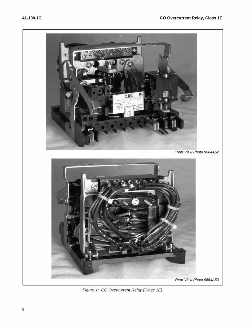
Figure 1: CO Overcurrent Relay (Class 1E)
Front View Photo 9664A52
Rear View Photo 9664A53
CO Overcurrent Relay, Class 1E 41-100.1C
9
Figure 2: Internal Schematic Of The Single Trip Relay Without IIT
Sub 23518A26
Sub 23518A27
Figure 3: Internal Schematic of the Single Trip Relay with IIT
41-100.1C CO Overcurrent Relay, Class 1E
10
Figure 5: Internal Schematic of the Double Trip Relay with IIT
Figure 4: Internal Schematic of the Double Trip Relay without IIT
Sub 23519A01
Sub 23530A01
CO Overcurrent Relay, Class 1E 41-100.1C
11
Figure 6: Internal Schematic of the Single Trip Relay with IIT Contacts to Separate Terminals
Sub 13526A43
Figure 7: Internal Schematic of Single Trip Relay with Torque Control Terminals without IIT
*Sub 43531A46
41-100.1C CO Overcurrent Relay, Class 1E
12
Figu
re 8
: E
xter
nal S
chem
atic
of C
O R
elay
for P
hase
and
Gro
und
Ove
rcur
rent
Pro
tect
ion
on a
Thr
ee P
hase
Sys
tem
Sub
318
2A75
5

CO Overcurrent Relay, Class 1E 41-100.1C
13
Figure 9: Typical Time Curve of the Type CO-2 Relay
Sub 1619509
41-100.1C CO Overcurrent Relay, Class 1E
14
Figure 10: Typical Time Curve of the Type CO-5 Relay
Sub 1619509Sub 1619510
CO Overcurrent Relay, Class 1E 41-100.1C
15
Figure 11: Typical Time Curve of the Type CO-6 Relay
Sub 1619511

41-100.1C CO Overcurrent Relay, Class 1E
16
Figure 12: Typical Time Curve of the Type CO-7 Relay
Sub 2619512
CO Overcurrent Relay, Class 1E 41-100.1C
17
Figure 13: Typical Time Curve of the Type CO-8 Relay
Sub 1619513

41-100.1C CO Overcurrent Relay, Class 1E
18
Figure 14: Typical Time Curve of the Type CO-9 Relay
Sub 1619514
CO Overcurrent Relay, Class 1E 41-100.1C
19
Figure 15: Typical Time Curve of the Type CO-11 Relay
Sub 1619515
IL 41-100.1C CO Overcurrent Relay - Class 1E
20
Figure 16 - Diagram of Test Connections for the Type CO Relay
Sub 33503A43

21
CO Overcurrent Relay - Class 1E IL 41-100.1C
Figure 17 - Outline & Drilling Plan for the Type CO Relay in Type FT-11 Case - Class 1E
Sub 43519A65

IL 41-100.1C CO Overcurrent Relay - Class 1E
22
This Page Reserved for Notes

23
CO Overcurrent Relay - Class 1E IL 41-100.1C
This Page Reserved for Notes
ABB Inc.4300 Coral Ridge DriveCoral Springs, Florida 33065Telephone: +1 954-752-6700Fax: +1 954-345-5329www.abb.com/substation automation
IL 4
1-10
0.1
- Rev
isio
n C
ABB