type code - josemaco's blog€¢ throughout this manual, the following abbreviations are used...
TRANSCRIPT

TYPE CODE
• Throughout this manual, the following abbreviations are used to identify individual type.
CODE AREA TYPE
CH China

A Few Words About SafetyService InformationThe service and repair information contained in this manual is intended for use by qualified, professional technicians.Attempting service or repairs without the proper training, tools, and equipment could cause injury to you or others. It could alsodamage the vehicle or create an unsafe condition.
This manual describes the proper methods and procedures for performing service, maintenance, and repairs. Some proceduresrequire the use of specially designed tools and dedicated equipment. Any person who intends to use a replacement part, serviceprocedure or a tool that is not recommended by Honda, must determine the risks to their personal safety and the safe operation ofthe vehicle.
If you need to replace a part, use genuine Honda parts with the correct part number or an equivalent part. We strongly recommendthat you do not use replacement parts of inferior quality.
For Your Customer’s SafetyProper service and maintenance are essential to the customer’s safety andthe reliability of the vehicle. Any error or oversight while servicing a vehiclecan result in faulty operation, damage to the vehicle, or injury to others.
For Your SafetyBecause this manual is intended for the professional service technician, wedo not provide warnings about many basic shop safety practices (e.g., Hotparts–wear gloves). If you have not received shop safety training or do notfeel confident about your knowledge of safe servicing practice, werecommended that you do not attempt to perform the procedures describedin this manual.
Some of the most important general service safety precautions are givenbelow. However, we cannot warn you of every conceivable hazard that canarise in performing service and repair procedures. Only you can decidewhether or not you should perform a given task.
Important Safety PrecautionsMake sure you have a clear understanding of all basic shop safety practices and that you are wearing appropriate clothing andusing safety equipment. When performing any service task, be especially careful of the following:
• Read all of the instructions before you begin, and make sure you have the tools, the replacement or repair parts, and the skillsrequired to perform the tasks safely and completely.
• Protect your eyes by using proper safety glasses, goggles or face shields any time you hammer, drill, grind, pry or work aroundpressurized air or liquids, and springs or other stored-energy components. If there is any doubt, put on eye protection.
• Use other protective wear when necessary, for example gloves or safety shoes. Handling hot or sharp parts can cause severeburns or cuts. Before you grab something that looks like it can hurt you, stop and put on gloves.
• Protect yourself and others whenever you have the vehicle up in the air. Any time you lift the vehicle, either with a hoist or a jack,make sure that it is always securely supported. Use jack stands.
Make sure the engine is off before you begin any servicing procedures, unless the instruction tells you to do otherwise.This will help eliminate several potential hazards:
• Carbon monoxide poisoning from engine exhaust. Be sure there is adequate ventilation whenever you run the engine.
• Burns from hot parts or coolant. Let the engine and exhaust system cool before working in those areas.
• Injury from moving parts. If the instruction tells you to run the engine, be sure your hands, fingers and clothing are out of the way.
Gasoline vapors and hydrogen gases from batteries are explosive. To reduce the possibility of a fire or explosion, be careful whenworking around gasoline or batteries.
• Use only a nonflammable solvent, not gasoline, to clean parts.
• Never drain or store gasoline in an open container.
• Keep all cigarettes, sparks and flames away from the battery and all fuel-related parts.
Improper service or repairs can create anunsafe condition that can cause your customeror others to be seriously hurt or killed.
Follow the procedures and precautions in thismanual and other service materials carefully.
Failure to properly follow instructions andprecautions can cause you to be seriously hurtor killed.
Follow the procedures and precautions in thismanual carefully.

Date of Issue: December, 2004©Honda Motor Co., Ltd.
HOW TO USE THIS MANUALThis service manual describes the service procedures for the CGR125 -5.
Follow the Maintenance Schedule (Section 3) recommendations toensure that the vehicle is in peak operating condition and the emissionlevels are within the standard set.
Performing the first scheduled maintenance is very important. Itcompensates for the initial wear that occurs during the break-in period.
Sections 1 and 3 apply to the whole motorcycle. Section 2 illustratesprocedures for removal/installation of components that may be requiredto perform service described in the following sections.Section 4 through 18 describe parts of the motorcycle, groupedaccording to location.
Find the section you want on this page, then turn to the table of contentson the first page of the section.
Most sections start with an assembly or system illustration, serviceinformation and troubleshooting for the section. The subsequent pagesgive detailed procedure.
If you don't know the source of the trouble, go to section 20Troubleshooting.
Your safety, and the safety of others, is very important. To help youmake informed decisions we have provided safety messages andother information throughout this manual. Of course, it is notpractical or possible to warn you about all the hazards associatedwith servicing this vehicle.You must use your own good judgement.You will find important safety information in a variety of formsincluding:• Safety Labels – on the vehicle• Safety Messages – preceded by a safety alert symbol and
one of three signal words, DANGER, WARNING, or CAUTION.These signal words mean:
You WILL be KILLED or SERIOUSLYHURT if you don’t follow instructions.
You CAN be KILLED or SERIOUSLY HURTif you don’t follow instructions.
You CAN be HURT if you don’t followinstructions.
• Instructions – how to service this vehicle correctly and safely.
As you read this manual, you will find information that is preceded by a symbol. The purpose of this message is to help prevent
damage to your vehicle, other property, or the environment.
ALL INFORMATION, ILLUSTRATIONS, DIREC-TIONS AND SPECIFICATIONS INCLUDED INTHIS PUBLICATION ARE BASED ON THE LAT-EST PRODUCT INFORMATION AVAILABLE ATTHE TIME OF APPROVAL FOR PRINTING.Honda Motor Co., Ltd. RESERVES THE RIGHTTO MAKE CHANGES AT ANY TIME WITHOUTNOTICE AND WITHOUT INCURRING ANY OBLI-GATION WHATSOEVER. NO PART OF THISPUBLICATION MAY BE REPRODUCED WITH-OUT WRITTEN PERMISSION. THIS MANUAL ISWRITTEN FOR PERSONS WHO HAVEACQUIRED BASIC KNOWLEDGE OF MAINTE-NANCE ON Honda MOTORCYCLES, MOTORSCOOTERS OR ATVS.
Honda Motor Co., Ltd.SERVICE PUBLICATION OFFICE
CONTENTS GENERAL INFORMATION
FRAME/BODY PANELS/EXHAUST SYSTEM MAINTENANCE LUBRICATION SYSTEM FUEL SYSTEM ENGINE REMOVAL/INSTALLATION CYLINDER HEAD/VALVES CYLINDER/PISTON/CAMSHAFT CLUTCH/GEARSHIFT LINKAGE ALTERNATOR/STARTER CLUTCH
CRANKSHAFT/TRANSMISSION/KICKSTARTERFRONT WHEEL/BRAKE/SUSPENSION/STEERING REAR WHEEL/BRAKE/SUSPENSION HYDRAULIC BRAKE 14
13
12
11
10
9
8
7
6
5
4
2
3
1
BATTERY/CHARGING SYSTEM IGNITION SYSTEM ELECTRIC STARTER LIGHTS/METERS/SWITCHES WIRING DIAGRAM TROUBLESHOOTING INDEX 21
20
19
18
17
16
15
EN
GIN
EC
HA
SS
ISE
LE
CT
RIC
AL
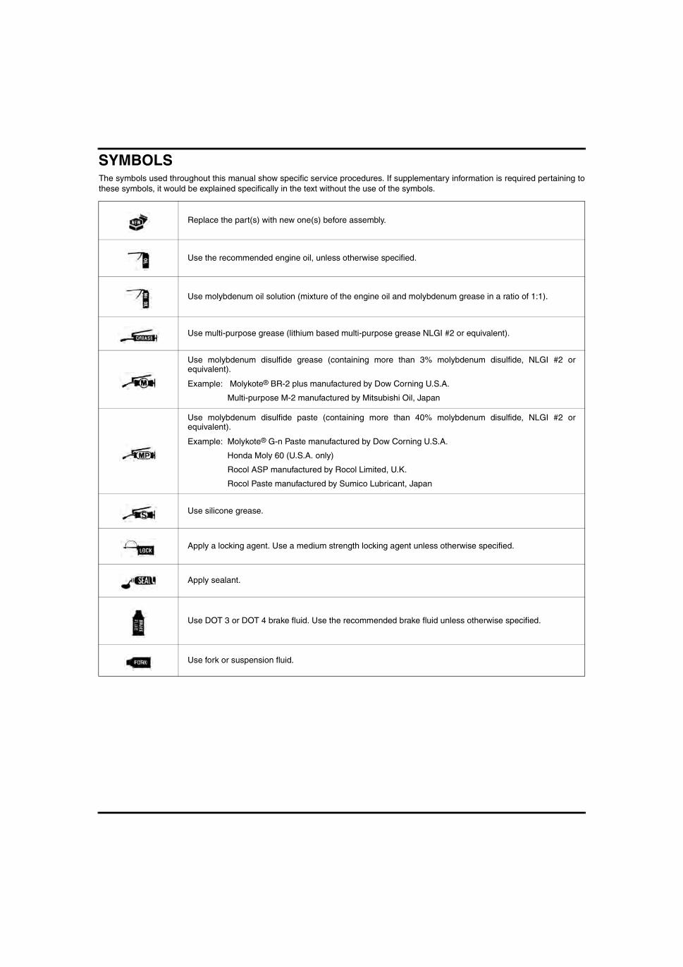
SYMBOLSThe symbols used throughout this manual show specific service procedures. If supplementary information is required pertaining tothese symbols, it would be explained specifically in the text without the use of the symbols.
Replace the part(s) with new one(s) before assembly.
Use the recommended engine oil, unless otherwise specified.
Use molybdenum oil solution (mixture of the engine oil and molybdenum grease in a ratio of 1:1).
Use multi-purpose grease (lithium based multi-purpose grease NLGI #2 or equivalent).
Use molybdenum disulfide grease (containing more than 3% molybdenum disulfide, NLGI #2 orequivalent).
Example: Molykote® BR-2 plus manufactured by Dow Corning U.S.A.
Multi-purpose M-2 manufactured by Mitsubishi Oil, Japan
Use molybdenum disulfide paste (containing more than 40% molybdenum disulfide, NLGI #2 orequivalent).
Example: Molykote® G-n Paste manufactured by Dow Corning U.S.A.
Honda Moly 60 (U.S.A. only)
Rocol ASP manufactured by Rocol Limited, U.K.
Rocol Paste manufactured by Sumico Lubricant, Japan
Use silicone grease.
Apply a locking agent. Use a medium strength locking agent unless otherwise specified.
Apply sealant.
Use DOT 3 or DOT 4 brake fluid. Use the recommended brake fluid unless otherwise specified.
Use fork or suspension fluid.

1-1
1
1. GENERAL INFORMATION
SERVICE RULES ············································ 1-2
MODEL IDENTIFICATION······························ 1-2
GENERAL SPECIFICATIONS························· 1-4
LUBRICATION SYSTEM SPECIFICATIONS · 1-5
FUEL SYSTEM SPECIFICATIONS················· 1-5
CYLINDER HEAD/VALVES SPECIFICATIONS··········································· 1-5
CYLINDER/PISTON SPECIFICATIONS········· 1-6
CLUTCH/GEARSHIFT LINKAGE SPECIFICATIONS··········································· 1-6
CRANKSHAFT/TRANSMISSION/KICKSTARTER SPECIFICATIONS ················· 1-7
FRONT WHEEL/BRAKE/SUSPENSION/STEERING SPECIFICATIONS························ 1-8
REAR WHEEL/BRAKE/SUSPENSION SPECIFICATIONS············································1-8
HYDRAULIC BRAKE SPECIFICATIONS (TYPE II, IV) ·····················································1-8
BATTERY/CHARGING SYSTEM SPECIFICATIONS············································1-9
IGNITION SYSTEM SPECIFICATIONS ··········1-9
ELECTRIC STARTER SPECIFICATIONS ········1-9
LIGHTS/METERS/SWITCHES SPECIFICATIONS············································1-9
STANDARD TORQUE VALUES ···················1-10
ENGINE & FRAME TORQUE VALUES ········1-10
LUBRICATION & SEAL POINTS ··················1-14
CABLE & HARNESS ROUTING ···················1-16
EMISSION CONTROL SYSTEMS ················1-25

GENERAL INFORMATION
1-2
GENERAL INFORMATION
SERVICE RULES1. Use genuine Honda or Honda-recommended parts and lubricants or their equivalents. Parts that do not meet Honda's
design specifications may cause damage to the motorcycle.2. Use the special tools designed for this product to avoid damage and incorrect assembly.3. Use only metric tools when servicing the motorcycle. Metric bolts, nuts and screws are not interchangeable with
English fasteners.4. Install new gaskets, O-rings, cotter pins, and lock plates when reassembling.5. When tightening bolts or nuts, begin with the larger diameter or inner bolt first. Then tighten to the specified torque
diagonally in incremental steps unless a particular sequence is specified.6. Clean parts in cleaning solvent upon disassembly. Lubricate any sliding surfaces before reassembly.7. After reassembly, check all parts for proper installation and operation.8. Route all electrical wires as shown in the Cable and Harness Routing (page 1-16).
MODEL IDENTIFICATIONThis manual covers 4 type of CGR125 models.
• Type I: Front drum brake • Type II: Front disc brake • Type III: Front drum brake/stripe color • Type IV: Front disc brake/stripe color
Type II shown

GENERAL INFORMATION
1-3
The frame serial number is stamped on the right side of the steeringhead.
The engine serial number is stamped on the left side of the lowercrankcase.
The carburetor identification number is stamped on the right side ofthe carburetor body.
The color label is attached as shown. When ordering color-codedparts, always specify the designated color code.
FRAME SERIAL NUMBER
ENGINE SERIAL NUMBER
CARBURETOR IDENTIFICATION NUMBER
COLOR LABEL
GENERAL INFORMATION
1-4
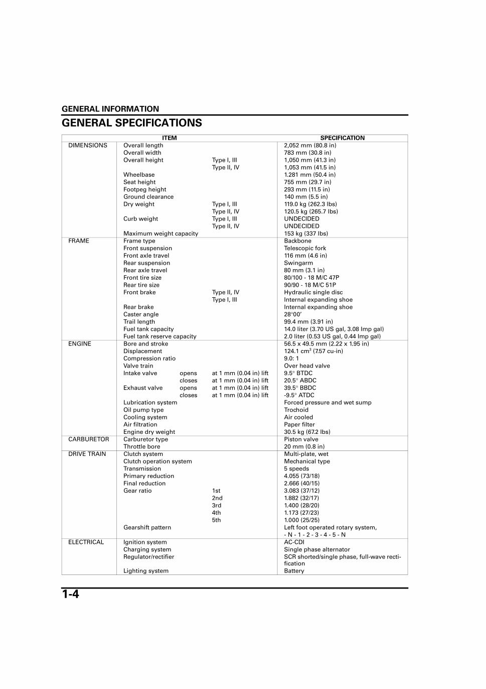
GENERAL SPECIFICATIONS
ITEM SPECIFICATION
DIMENSIONS Overall length 2,052 mm (80.8 in)Overall width 783 mm (30.8 in)Overall height Type I, III 1,050 mm (41.3 in)
Type II, IV 1,053 mm (41.5 in)Wheelbase 1.281 mm (50.4 in)Seat height 755 mm (29.7 in)Footpeg height 293 mm (11.5 in)Ground clearance 140 mm (5.5 in)Dry weight Type I, III 119.0 kg (262.3 lbs)
Type II, IV 120.5 kg (265.7 lbs)Curb weight Type I, III UNDECIDED
Type II, IV UNDECIDEDMaximum weight capacity 153 kg (337 lbs)
FRAME Frame type BackboneFront suspension Telescopic forkFront axle travel 116 mm (4.6 in)Rear suspension SwingarmRear axle travel 80 mm (3.1 in)Front tire size 80/100 - 18 M/C 47PRear tire size 90/90 - 18 M/C 51PFront brake Type II, IV Hydraulic single disc
Type I, III Internal expanding shoeRear brake Internal expanding shoeCaster angle 28°00’Trail length 99.4 mm (3.91 in)Fuel tank capacity 14.0 liter (3.70 US gal, 3.08 Imp gal)Fuel tank reserve capacity 2.0 liter (0.53 US gal, 0.44 Imp gal)
ENGINE Bore and stroke 56.5 x 49.5 mm (2.22 x 1.95 in)Displacement 124.1 cm3 (7.57 cu-in)Compression ratio 9.0: 1Valve train Over head valveIntake valve opens at 1 mm (0.04 in) lift 9.5° BTDC
closes at 1 mm (0.04 in) lift 20.5° ABDCExhaust valve opens at 1 mm (0.04 in) lift 39.5° BBDC
closes at 1 mm (0.04 in) lift -9.5° ATDCLubrication system Forced pressure and wet sumpOil pump type TrochoidCooling system Air cooledAir filtration Paper filterEngine dry weight 30.5 kg (67.2 lbs)
CARBURETOR Carburetor type Piston valveThrottle bore 20 mm (0.8 in)
DRIVE TRAIN Clutch system Multi-plate, wetClutch operation system Mechanical typeTransmission 5 speedsPrimary reduction 4.055 (73/18)Final reduction 2.666 (40/15)Gear ratio 1st 3.083 (37/12)
2nd 1.882 (32/17)3rd 1.400 (28/20)4th 1.173 (27/23)5th 1.000 (25/25)
Gearshift pattern Left foot operated rotary system,- N - 1 - 2 - 3 - 4 - 5 - N
ELECTRICAL Ignition system AC-CDICharging system Single phase alternatorRegulator/rectifier SCR shorted/single phase, full-wave recti-
ficationLighting system Battery

GENERAL INFORMATION
1-5
LUBRICATION SYSTEM SPECIFICATIONSUnit: mm (in)
FUEL SYSTEM SPECIFICATIONS
CYLINDER HEAD/VALVES SPECIFICATIONSUnit: mm (in)
ITEM STANDARD SERVICE LIMIT
Engine oil capacity
After draining 0.8 liter (0.8 US qt, 0.7 lmp qt) –After disassembly 1.1 liter (1.2 US qt, 1.0 lmp qt) –
Recommended engine oil Honda 4-stroke oil or equivalent motor oilAPI service classification: SF or SG Viscosity: SAE 10W-30
–
Oil pump rotor
Tip clearance 0.15 (0.006) 0.20 (0.008)Body clearance 0.15 – 0.21 (0.006 – 0.008) 0.40 (0.016)Side clearance 0.09 – 0.16 (0.004 – 0.006) 0.25 (0.010)
ITEM SPECIFICATIONS
Carburetor identification number PDCBEMain jet #95Slow jet #38Pilot screw initial/final opening See page 5-21Float level 14.0 mm (0.55 in)Idle speed 1,400 ± 100 min-1 (rpm)Throttle grip free play 2.0 – 6.0 mm (0.08 – 0.24 in)PAIR control valve specified vacuum 60 kPa (450 mm Hg)
ITEM STANDARD SERVICE LIMIT
Cylinder compression 1,226 kPa (12.5 kgf/cm2, 178 psi)at 450 min-1 (rpm)
–
Valve clearance IN/EX 0.08 ± 0.02 (0.003 ± 0.001) –Valve,valve guide
Valve stem O.D. IN 5.450 – 5.465 (0.2146 – 0.2152) 5.42 (0.213)EX 5.430 – 5.445 (0.2138 – 0.2144) 5.40 (0.213)
Valve guide I.D. IN/EX 5.475 – 5.485 (0.2156 – 0.2159) 5.50 (0.217)Stem-to-guide clear-ance
IN 0.010 – 0.035 (0.0004 – 0.0014) 0.12 (0.005)EX 0.030 – 0.055 (0.0012 – 0.0022) 0.14 (0.006)
Valve seat width IN/EX 1.2 – 1.5 (0.05 – 0.06) 2.0 (0.08)Valve spring free length
Inner IN/EX 33.5 (1.32) 30.0 (1.18)Outer IN/EX 40.9 (1.61) 39.8 (1.57)
Push rod length 141.15 – 141.45 (5.557 – 5.569) 141.0 (5.55)Rocker arm Arm I.D. IN/EX 12.000 – 12.018 (0.4724 – 0.4731) 12.05 (0.474)
Shaft O.D. IN/EX 11.977 – 11.995 (0.4715 – 0.4722) 11.95 (0.470)Arm holder I.D IN/EX 12.000 – 12.027 (0.4724 – 0.4735) 12.05 (0.474)Arm-to-shaft clear-ance
IN/EX 0.005 – 0.041 (0.0002 – 0.0016) 0.10 (0.004)
Cylinder head warpage – 0.05 (0.002)
GENERAL INFORMATION
1-6
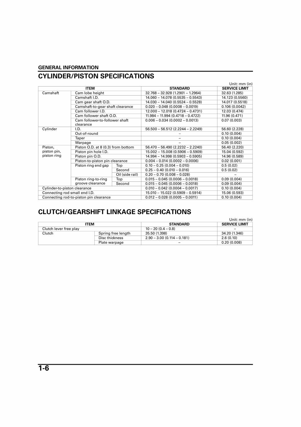
CYLINDER/PISTON SPECIFICATIONSUnit: mm (in)
CLUTCH/GEARSHIFT LINKAGE SPECIFICATIONSUnit: mm (in)
ITEM STANDARD SERVICE LIMIT
Camshaft Cam lobe height 32.768 – 32.928 (1.2901 – 1.2964) 32.63 (1.285)Camshaft I.D. 14.060 – 14.078 (0.5535 – 0.5543) 14.123 (0.5560)Cam gear shaft O.D. 14.030 – 14.040 (0.5524 – 0.5528) 14.017 (0.5518)Camshaft-to-gear shaft clearance 0.020 – 0.048 (0.0008 – 0.0019) 0.106 (0.0042)Cam follower I.D. 12.000 – 12.018 (0.4724 – 0.4731) 12.03 (0.474)Cam follower shaft O.D. 11.984 – 11.994 (0.4718 – 0.4722) 11.96 (0.471)Cam follower-to-follower shaft clearance
0.006 – 0.034 (0.0002 – 0.0013) 0.07 (0.003)
Cylinder I.D. 56.500 – 56.512 (2.2244 – 2.2249) 56.60 (2.228)Out-of-round – 0.10 (0.004)Taper – 0.10 (0.004)Warpage – 0.05 (0.002)
Piston,piston pin, piston ring
Piston O.D. at 8 (0.3) from bottom 56.470 – 56.490 (2.2232 – 2.2240) 56.40 (2.220)Piston pin hole I.D. 15.002 – 15.008 (0.5906 – 0.5909) 15.04 (0.592)Piston pin O.D. 14.994 – 14.998 (0.5903 – 0.5905) 14.96 (0.589)Piston-to-piston pin clearance 0.004 – 0.014 (0.0002 – 0.0006) 0.02 (0.001)Piston ring end gap Top 0.10 – 0.25 (0.004 – 0.010) 0.5 (0.02)
Second 0.25 – 0.40 (0.010 – 0.016) 0.5 (0.02)Oil (side rail) 0.20 – 0.70 (0.008 – 0.028) –
Piston ring-to-ring groove clearance
Top 0.015 – 0.045 (0.0006 – 0.0018) 0.09 (0.004)Second 0.015 – 0.045 (0.0006 – 0.0018) 0.09 (0.004)
Cylinder-to-piston clearance 0.010 – 0.042 (0.0004 – 0.0017) 0.10 (0.004)Connecting rod small end I.D. 15.010 – 15.022 (0.5909 – 0.5914) 15.06 (0.593)Connecting rod-to-piston pin clearance 0.012 – 0.028 (0.0005 – 0.0011) 0.10 (0.004)
ITEM STANDARD SERVICE LIMIT
Clutch lever free play 10 – 20 (0.4 – 0.8) –Clutch Spring free length 35.50 (1.398) 34.20 (1.346)
Disc thickness 2.90 – 3.00 (0.114 – 0.181) 2.6 (0.10)Plate warpage – 0.20 (0.008)

GENERAL INFORMATION
1-7
CRANKSHAFT/TRANSMISSION/KICKSTARTER SPECIFICATIONSUnit: mm (in)
ITEM STANDARD SERVICE LIMIT
Crankshaft Connecting rod side clearance 0.10 – 0.30 (0.004 – 0.012) 0.5 (0.02)Connecting rod radial clearance 0.008 – 0.018 (0.0003 – 0.0007) 0.05 (0.002)Runout – 0.02 (0.001)
Transmission Gear I.D. M3, M5 20.020 – 20.041 (0.7882 – 0.7890) 20.07 (0.790)C1 19.520 – 19.541 (0.7685 – 0.7693) 19.57 (0.770)C2 22.000 – 22.021 (0.8661 – 0.8670) 22.05 (0.868)C4 20.020 – 20.041 (0.7882 – 0.7890) 20.07 (0.790)
Bushing O.D. C1 19.479 – 19.500 (0.7669 – 0.7677) 19.43 (0.765)Bushing I.D. C1 16.516 – 16.534 (0.6502 – 0.6509) 16.60 (0.654)Gear-to-bushing clear-ance
C1 0.020 – 0.062 (0.0008 – 0.0024) 0.10 (0.004)
Mainshaft O.D. M3 19.959 – 19.980 (0.7858 – 0.7866) 19.91 (0.784)Countershaft O.D. C1 16.466 – 16.484 (0.6483 – 0.6490) 16.41 (0.646)
C2 21.959 – 21.980 (0.8645 – 0.8654) 21.91 (0.863)C4 19.959 – 19.980 (0.7858 – 0.7866) 19.91 (0.784)
Gear-to-shaft clear-ance
M3 0.040 – 0.082 (0.0016 – 0.0032) 0.10 (0.004)C2 0.020 – 0.062 (0.0008 – 0.0024) 0.10 (0.004)C4 0.040 – 0.082 (0.0016 – 0.0032) 0.10 (0.004)
Bushing-to-shaft clear-ance
C1 0.032 – 0.068 (0.0013 – 0.0027) 0.10 (0.004)
Shift fork I.D. 12.000 – 12.018 (0.4724 – 0.4731) 12.05 (0.474)Claw thickness 4.93 – 5.00 (0.194 – 0.197) 4.50 (0.177)Shaft O.D. 11.976 – 11.994 (0.4715 – 0.4722) 11.96 (0.471)
Kickstarter Pinion gear I.D. 20.000 – 20.021 (0.7874 – 0.7882) 20.05 (0.789)Spindle O.D. 19.966 – 19.984 (0.7861 – 0.7868) 19.90 (0.783)
GENERAL INFORMATION
1-8
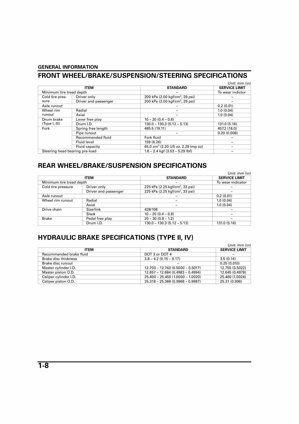
FRONT WHEEL/BRAKE/SUSPENSION/STEERING SPECIFICATIONSUnit: mm (in)
REAR WHEEL/BRAKE/SUSPENSION SPECIFICATIONSUnit: mm (in)
HYDRAULIC BRAKE SPECIFICATIONS (TYPE II, IV)Unit: mm (in)
ITEM STANDARD SERVICE LIMIT
Minimum tire tread depth – To wear indictorCold tire pres-sure
Driver only 200 kPa (2.00 kgf/cm2, 29 psi) –Driver and passenger 200 kPa (2.00 kgf/cm2, 29 psi) –
Axle runout – 0.2 (0.01)Wheel rim runout
Radial – 1.0 (0.04)Axial – 1.0 (0.04)
Drum brake (Type I, III)
Lever free play 10 – 20 (0.4 – 0.8) –Drum I.D. 130.0 – 130.3 (5.12 – 5.13) 131.0 (5.16)
Fork Spring free length 485.5 (19.11) 457.2 (18.0)Pipe runout – 0.20 (0.008)Recommended fluid Fork fluid –Fluid level 159 (6.26) –Fluid capacity 65.0 cm3 (2.20 US oz, 2.29 lmp oz) –
Steering head bearing pre-load 1.6 – 2.4 kgf (3.53 – 5.29 lbf) –
ITEM STANDARD SERVICE LIMIT
Minimum tire tread depth – To wear indicatorCold tire pressure Driver only 225 kPa (2.25 kgf/cm2, 33 psi) –
Driver and passenger 225 kPa (2.25 kgf/cm2, 33 psi) –Axle runout – 0.2 (0.01)Wheel rim runout Radial – 1.0 (0.04)
Axial – 1.0 (0.04)Drive chain Size/link 428/108 –
Slack 10 – 20 (0.4 – 0.8) –Brake Pedal free play 20 – 30 (0.8 – 1.2) –
Drum I.D. 130.0 – 130.3 (5.12 – 5.13) 131.0 (5.16)
ITEM STANDARD SERVICE LIMIT
Recommended brake fluid DOT 3 or DOT 4 –Brake disc thickness 3.8 – 4.2 (0.15 – 0.17) 3.5 (0.14)Brake disc runout – 0.25 (0.010)Master cylinder I.D. 12.700 – 12.743 (0.5000 – 0.5017) 12.755 (0.5022)Master piston O.D. 12.657 – 12.684 (0.4983 – 0.4994) 12.645 (0.4978)Caliper cylinder I.D. 25.400 – 25.450 (1.0000 – 1.0020) 25.460 (1.0024)Caliper piston O.D. 25.318 – 25.368 (0.9968 – 0.9987) 25.31 (0.996)

GENERAL INFORMATION
1-9
BATTERY/CHARGING SYSTEM SPECIFICATIONS
IGNITION SYSTEM SPECIFICATIONS
ELECTRIC STARTER SPECIFICATIONSUnit: mm (in)
LIGHTS/METERS/SWITCHES SPECIFICATIONS
ITEM SPECIFICATION
Battery Capacity 12 V – 7 AhCurrent leakage 0.1 mA max.Specific gravity
Fully charged 1.270 – 1.290 (20°C/68°F)Needs charging Below 1.230 (20°C/68°F)
Voltage Fully charged Above 12.8 VNeeds charging Below 12.3 V
Charging current
Normal 0.8 A/5 – 10 hQuick 8 A/1 h
Alternator Capacity 0.130 kW/5,000 min-1 (rpm)Charging coil resistance 0.3 – 1.2 Ω (20°C/68°F)
ITEM SPECIFICATIONS
Spark plug Standard DPR8EA-9 (NGK)For extended high speed riding DPR9EA-9 (NGK)
Spark plug gap 0.80 – 0.90 mm (0.031 – 0.035 in)Ignition coil primary peak voltage 100 V minimumExciter coil peak voltage 100 V minimumIgnition pulse generator peak voltage 0.7 V minimumIgnition timing ("F" mark) 15° BTDC at idle
ITEM STANDARD SERVICE LIMIT
Starter motor brush length 12.5 (0.49) 6.5 (0.26)
ITEM SPECIFICATION
Bulbs Headlight (Hi/low beam) 12 V - 35/35 WBrake/tail light 12 V - 21/5 WTurn signal light 12 V - 10 W x 4Position light 12 V - 4 WInstrument light 12 V - 1.7 W x 4Turn signal indicator 12 V - 3.4 W x 2High-beam indicator 12 V - 3.4 WNeutral indicator 12 V - 3.4 W
Fuse 15 AFuel level sensor resistance(20°C/68°F)
Full 4 – 10 ΩEmpty 97.5 – 107.5 Ω
GENERAL INFORMATION
1-10
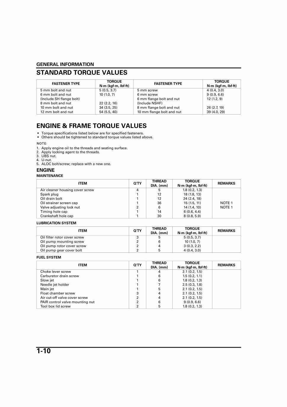
STANDARD TORQUE VALUES
ENGINE & FRAME TORQUE VALUES • Torque specifications listed below are for specified fasteners. • Others should be tightened to standard torque values listed above.
1. Apply engine oil to the threads and seating surface.2. Apply locking agent to the threads.3. UBS nut.4. U-nut.5. ALOC bolt/screw; replace with a new one.
ENGINEMAINTENANCE
LUBRICATION SYSTEM
FUEL SYSTEM
FASTENER TYPETORQUE
FASTENER TYPETORQUE
N·m (kgf·m, lbf·ft) N·m (kgf·m, lbf·ft)
5 mm bolt and nut 5 (0.5, 3.7) 5 mm screw 4 (0.4, 3.0)6 mm bolt and nut 10 (1.0, 7) 6 mm screw 9 (0.9, 6.6)(Include SH flange bolt) 6 mm flange bolt and nut 12 (1.2, 9)8 mm bolt and nut 22 (2.2, 16) (Include NSHF)10 mm bolt and nut 34 (3.5, 25) 8 mm flange bolt and nut 26 (2.7, 19)12 mm bolt and nut 54 (5.5, 40) 10 mm flange bolt and nut 39 (4.0, 29)
ITEM Q'TYTHREAD TORQUE
REMARKSDIA. (mm) N·m (kgf·m, lbf·ft)
Air cleaner housing cover screw 4 5 1.8 (0.2, 1.3)Spark plug 1 12 18 (1.8, 13)Oil drain bolt 1 12 24 (2.4, 18)Oil strainer screen cap 1 36 15 (1.5, 11) NOTE 1Valve adjusting lock nut 2 6 14 (1.4, 10) NOTE 1Timing hole cap 1 14 6 (0.6, 4.4)Crankshaft hole cap 1 30 8 (0.8, 5.9)
ITEM Q'TYTHREAD TORQUE
REMARKSDIA. (mm) N·m (kgf·m, lbf·ft)
Oil filter rotor cover screw 3 5 5 (0.5, 3.7)Oil pump mounting screw 2 6 10 (1.0, 7)Oil pump rotor cover screw 2 4 3 (0.3, 2.2)Oil pump gear cover bolt 2 5 4 (0.4, 3.0)
ITEM Q'TYTHREAD TORQUE
REMARKSDIA. (mm) N·m (kgf·m, lbf·ft)
Choke lever screw 1 4 2.1 (0.2, 1.5)Carburetor drain screw 1 6 1.5 (0.2, 1.1)Slow jet 1 6 1.8 (0.2, 1.3)Needle jet holder 1 7 2.5 (0.3, 1.8)Main jet 1 5 2.1 (0.2, 1.5)Float chamber screw 3 4 2.1 (0.2, 1.5)Air cut-off valve cover screw 2 4 2.1 (0.2, 1.5)PAIR control valve mounting nut 2 6 9 (0.9, 6.6)Tool box lid screw 2 5 1.8 (0.2, 1.3)

GENERAL INFORMATION
1-11
CYLINDER HEAD/VALVE
CLUTCH/GEARSHIFT LINKAGE
ALTERNATOR/STARTER CLUTCH
CRANKSHAFT/TRANSMISSION/KICK STARTER
ITEM Q'TYTHREAD TORQUE
REMARKSDIA. (mm) N·m (kgf·m, lbf·ft)
Cylinder head nut 4 8 32 (3.3, 24) NOTE 1Cylinder head bolt 1 8 20 (2.0, 15)Cylinder bolt 2 6 10 (1.0, 7)Rocker arm shaft bolt 3 6 12 (1.2, 9)
ITEM Q'TYTHREAD TORQUE
REMARKSDIA. (mm) N·m (kgf·m, lbf·ft)
Clutch lifter plate bolt 4 6 12 (1.2, 9)Shift drum stopper arm bolt 1 6 12 (1.2, 9)Oil filter rotor lock nut 1 16 54 (5.5, 40) NOTE 1Oil filter rotor cover screw 3 5 5 (0.5, 3.7)Kickstarter pedal pinch bolt 1 8 27 (2.8, 20)
ITEM Q'TYTHREAD TORQUE
REMARKSDIA. (mm) N·m (kgf·m, lbf·ft)
Starter clutch socket bolt 3 6 16 (1.6, 12) NOTE 2Flywheel bolt 1 10 74 (7.5, 55) NOTE 1Ignition pulse generator mounting bolt 2 5 5 (0.5, 3.7) NOTE 2
ITEM Q'TYTHREAD TORQUE
REMARKSDIA. (mm) N·m (kgf·m, lbf·ft)
Push plug holder bolt 1 6 13 (1.3, 10)
GENERAL INFORMATION
1-12
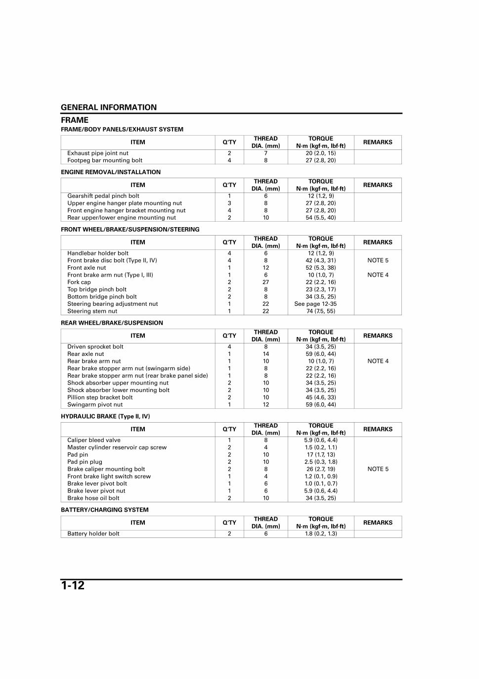
FRAMEFRAME/BODY PANELS/EXHAUST SYSTEM
ENGINE REMOVAL/INSTALLATION
FRONT WHEEL/BRAKE/SUSPENSION/STEERING
REAR WHEEL/BRAKE/SUSPENSION
HYDRAULIC BRAKE (Type II, IV)
BATTERY/CHARGING SYSTEM
ITEM Q'TYTHREAD TORQUE
REMARKSDIA. (mm) N·m (kgf·m, lbf·ft)
Exhaust pipe joint nut 2 7 20 (2.0, 15)Footpeg bar mounting bolt 4 8 27 (2.8, 20)
ITEM Q'TYTHREAD TORQUE
REMARKSDIA. (mm) N·m (kgf·m, lbf·ft)
Gearshift pedal pinch bolt 1 6 12 (1.2, 9)Upper engine hanger plate mounting nut 3 8 27 (2.8, 20)Front engine hanger bracket mounting nut 4 8 27 (2.8, 20)Rear upper/lower engine mounting nut 2 10 54 (5.5, 40)
ITEM Q'TYTHREAD TORQUE
REMARKSDIA. (mm) N·m (kgf·m, lbf·ft)
Handlebar holder bolt 4 6 12 (1.2, 9)Front brake disc bolt (Type II, IV) 4 8 42 (4.3, 31) NOTE 5Front axle nut 1 12 52 (5.3, 38)Front brake arm nut (Type I, III) 1 6 10 (1.0, 7) NOTE 4Fork cap 2 27 22 (2.2, 16)Top bridge pinch bolt 2 8 23 (2.3, 17)Bottom bridge pinch bolt 2 8 34 (3.5, 25)Steering bearing adjustment nut 1 22 See page 12-35Steering stem nut 1 22 74 (7.5, 55)
ITEM Q'TYTHREAD TORQUE
REMARKSDIA. (mm) N·m (kgf·m, lbf·ft)
Driven sprocket bolt 4 8 34 (3.5, 25)Rear axle nut 1 14 59 (6.0, 44)Rear brake arm nut 1 10 10 (1.0, 7) NOTE 4Rear brake stopper arm nut (swingarm side) 1 8 22 (2.2, 16)Rear brake stopper arm nut (rear brake panel side) 1 8 22 (2.2, 16)Shock absorber upper mounting nut 2 10 34 (3.5, 25)Shock absorber lower mounting bolt 2 10 34 (3.5, 25)Pillion step bracket bolt 2 10 45 (4.6, 33)Swingarm pivot nut 1 12 59 (6.0, 44)
ITEM Q'TYTHREAD TORQUE
REMARKSDIA. (mm) N·m (kgf·m, lbf·ft)
Caliper bleed valve 1 8 5.9 (0.6, 4.4)Master cylinder reservoir cap screw 2 4 1.5 (0.2, 1.1)Pad pin 2 10 17 (1.7, 13)Pad pin plug 2 10 2.5 (0.3, 1.8)Brake caliper mounting bolt 2 8 26 (2.7, 19) NOTE 5Front brake light switch screw 1 4 1.2 (0.1, 0.9)Brake lever pivot bolt 1 6 1.0 (0.1, 0.7)Brake lever pivot nut 1 6 5.9 (0.6, 4.4)Brake hose oil bolt 2 10 34 (3.5, 25)
ITEM Q'TYTHREAD TORQUE
REMARKSDIA. (mm) N·m (kgf·m, lbf·ft)
Battery holder bolt 2 6 1.8 (0.2, 1.3)

GENERAL INFORMATION
1-13
LIGHTS/METERS/SWITCHES
OTHERS
ITEM Q'TYTHREAD TORQUE
REMARKSDIA. (mm) N·m (kgf·m, lbf·ft)
Ignition switch mounting bolt 2 8 24 (2.4, 18)
ITEM Q'TYTHREAD TORQUE
REMARKSDIA. (mm) N·m (kgf·m, lbf·ft)
Clutch lever pivot bolt 1 6 5.9 (0.6, 4.4)Clutch lever pivot nut 1 6 1 (0.1, 0.7)Brake lever pivot bolt (Type I, III) 1 6 1 (0.1, 0.7)Brake lever pivot nut (Type I, III) 1 6 5.9 (0.6, 4.4)Side stand pivot bolt 1 10 45(4.6, 33)
GENERAL INFORMATION
1-14
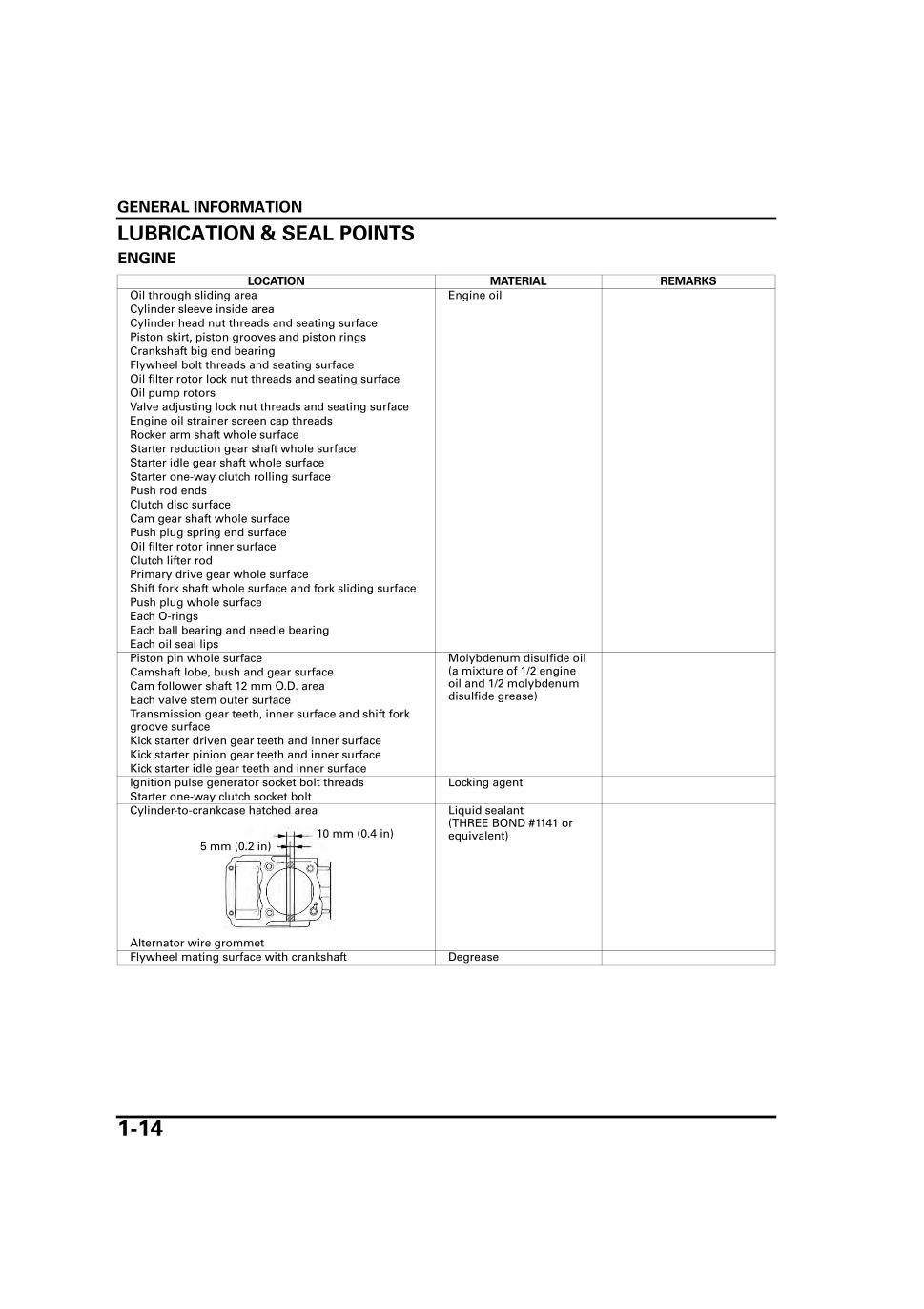
LUBRICATION & SEAL POINTSENGINE
LOCATION MATERIAL REMARKS
Oil through sliding area Engine oilCylinder sleeve inside areaCylinder head nut threads and seating surfacePiston skirt, piston grooves and piston ringsCrankshaft big end bearingFlywheel bolt threads and seating surfaceOil filter rotor lock nut threads and seating surfaceOil pump rotorsValve adjusting lock nut threads and seating surfaceEngine oil strainer screen cap threadsRocker arm shaft whole surfaceStarter reduction gear shaft whole surfaceStarter idle gear shaft whole surfaceStarter one-way clutch rolling surfacePush rod endsClutch disc surfaceCam gear shaft whole surfacePush plug spring end surfaceOil filter rotor inner surfaceClutch lifter rodPrimary drive gear whole surfaceShift fork shaft whole surface and fork sliding surfacePush plug whole surfaceEach O-ringsEach ball bearing and needle bearingEach oil seal lipsPiston pin whole surface Molybdenum disulfide oil
(a mixture of 1/2 engine oil and 1/2 molybdenum disulfide grease)
Camshaft lobe, bush and gear surfaceCam follower shaft 12 mm O.D. areaEach valve stem outer surfaceTransmission gear teeth, inner surface and shift fork groove surfaceKick starter driven gear teeth and inner surfaceKick starter pinion gear teeth and inner surfaceKick starter idle gear teeth and inner surfaceIgnition pulse generator socket bolt threads Locking agentStarter one-way clutch socket boltCylinder-to-crankcase hatched area Liquid sealant
(THREE BOND #1141 or equivalent)
Alternator wire grommetFlywheel mating surface with crankshaft Degrease
5 mm (0.2 in)10 mm (0.4 in)

GENERAL INFORMATION
1-15
FRAME
LOCATION MATERIAL REMARKS
Steering bearing race and bearingSteering stem dust seal lips
Urea based multi-purpose grease for extreme pres-sure (example: Shell ALVANIA EP2 or MOBIL MH008) or equivalent
Spread 3.0 g to each bear-ing race
Front wheel dust seal lip surface Multi-purpose greaseSpeedometer gear teeth Inject 3.0 - 5.0 gSpeedometer gear inner surfaceSpeedometer pinion shaft Spread 0.5 - 1.0 gSpeedometer cable (Inside of casing)Front brake cam and shaft surface (Type I, III) No grease on lining surfaceFront brake panel anchor pin sliding area (Type I, III) No grease on lining surfaceFront brake panel dust seal lip surface (Type I, III)Rear wheel driven flange dust seal lip surfaceRear wheel O-ring whole surfaceRear brake cam and shaft surface No grease on lining surfaceRear brake panel anchor pin sliding area No grease on lining surfaceBrake caliper bracket pin sliding surface (Type II, IV)Side stand pivot sliding areaMain stand pivot sliding areaRear brake pedal pivot sliding areaThrottle pipe cable contacting areaFront brake lever pivot bolt sliding surface (Type I, III) Spread 0.1 gClutch lever pivot bolt sliding surfaceEach bearing rotating areaFront brake cam felt seal whole surface (type I, III)Rear brake cam felt seal whole surface
Gear oil (IDEMITSU AUTOLUB 30 or MECHANIC 44 or equiva-lent)
Brake master cylinder cups (Type II, IV) DOT 3 or DOT 4 brake fluidBrake master cylinder piston sliding surface (Type II, IV)
Brake caliper piston seal lips (Type II, IV)Brake caliper piston sliding surface (Type II, IV)Throttle cable (Inside of casing) Silicone greaseClutch cable (Inside of casing)Brake cable (Inside of casing)Brake lever pivot sliding surface (Type II, IV) Spread 0.1 gBrake caliper slide pin sliding surface (Type II, IV) Spread 0.4 g minimumBrake caliper dust seal lipsBrake master cylinder piston and brake lever contact surface (Type II, IV)
Spread 0.1 g
Fork socket bolt threads Locking agentFork cap O-ring Fork fluidFork slider bushing surfaceFork oil seal lips and dust seal lipsHandlebar grip inner surface Honda Bond A or equiva-
lent
GENERAL INFORMATION
1-16
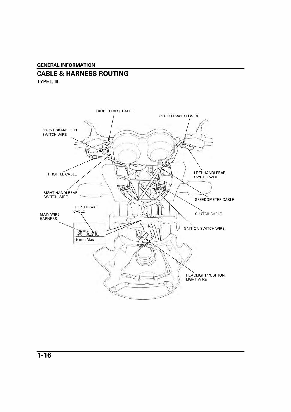
CABLE & HARNESS ROUTING
TYPE I, III:
FRONT BRAKE CABLE
THROTTLE CABLE
CLUTCH CABLE
SPEEDOMETER CABLE
LEFT HANDLEBAR SWITCH WIRE
HEADLIGHT/POSITION LIGHT WIRE
RIGHT HANDLEBAR SWITCH WIRE
FRONT BRAKE LIGHT SWITCH WIRE
IGNITION SWITCH WIRE
CLUTCH SWITCH WIRE
MAIN WIRE HARNESS
FRONT BRAKE CABLE
5 mm Max

GENERAL INFORMATION
1-17
TYPE II, IV:
THROTTLE CABLE
FRONT BRAKE HOSE
CLUTCH CABLE
SPEEDOMETER CABLE
LEFT HANDLEBAR SWITCH WIRE
HEADLIGHT/POSITION LIGHT WIRE
RIGHT HANDLEBAR SWITCH WIRE
FRONT BRAKE LIGHT SWITCH WIRE
IGNITION SWITCH WIRE
CLUTCH SWITCH WIRE
MAIN WIRE HARNESS
5 mm Max

GENERAL INFORMATION
1-18
TYPE I, III:
LEFT HANDLEBAR SWITCH WIRE
REGULATOR/RECTIFIER WIRE
HORN WIRE
CLUTCH CABLE
FRONT BRAKE CABLE
THROTTLE CABLE
SPEEDOMETER CABLE

GENERAL INFORMATION
1-19
TYPE II, IV:
LEFT HANDLEBAR SWITCH WIRE
REGULATOR/RECTIFIER WIRE
HORN WIRE
CLUTCH CABLE
FRONT BRAKE HOSE
THROTTLE CABLE
SPEEDOMETER CABLE
GENERAL INFORMATION
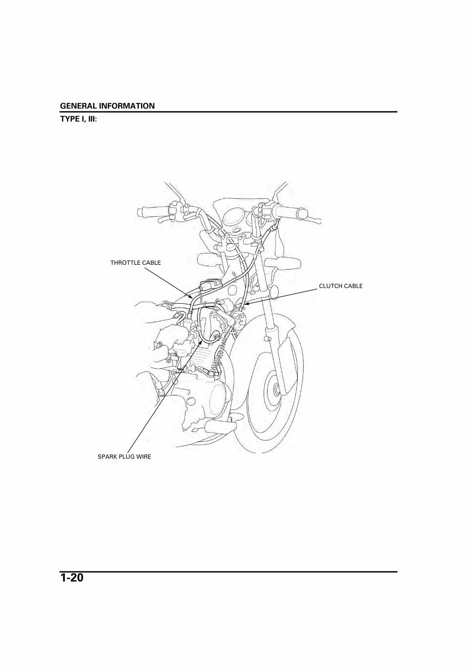
1-20
TYPE I, III:
THROTTLE CABLE
CLUTCH CABLE
SPARK PLUG WIRE
GENERAL INFORMATION
1-21
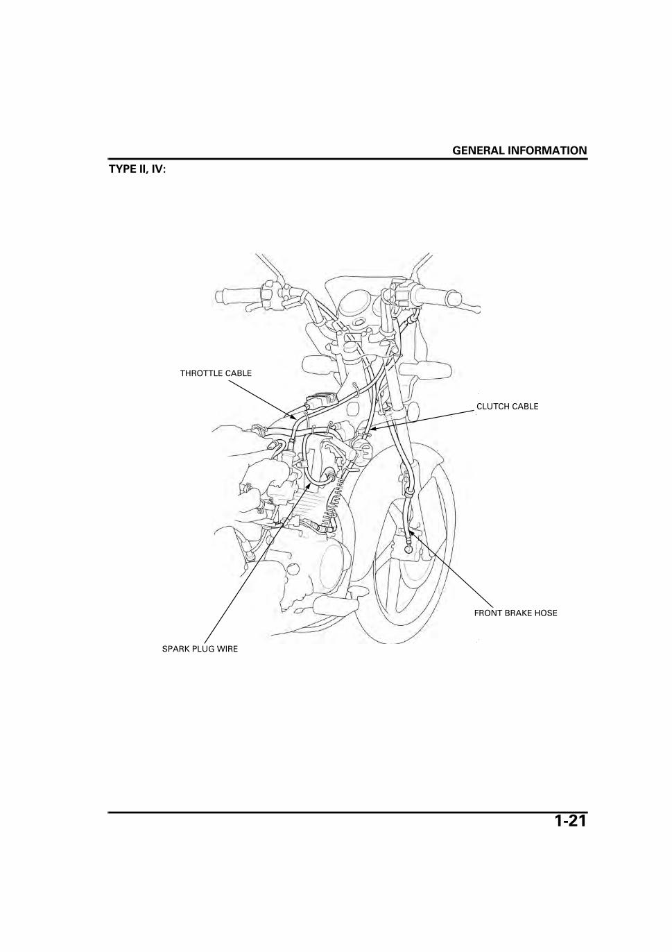
TYPE II, IV:
FRONT BRAKE HOSE
THROTTLE CABLE
CLUTCH CABLE
SPARK PLUG WIRE

GENERAL INFORMATION
1-22
ALL TYPES:
REGULATOR/RECTIFIER WIRE
HORN WIRE
PULSE SECONDARY AIR INJECTION (PAIR) CONTROL VALVE VACUUM HOSE
TURN SIGNAL RELAY WIRE
CARBURETOR DRAIN HOSE
BATTERY POSITIVE (+) CABLE
STARTER MOTOR CABLE
BATTERY BREATHER HOSE
BATTERY NEGATIVE (–) CABLE
MAIN WIRE HARNESS

GENERAL INFORMATION
1-23
ALL TYPES:
THROTTLE CABLE
AIR CLEANER SUB FILTER -to-OPEN AIR HOSE
CARBURETOR AIR VENT HOSE
SPARK PLUG WIRE
CLUTCH CABLECRANKCASE BREATHER HOSE
REAR BRAKE LIGHT SWITCH
IGNITION CONTROL MODULE WIRE
SUB FILTER-to-PAIR CONTROL VALVE HOSE

GENERAL INFORMATION
1-24
ALL TYPES:
RIGHT REAR TURN SIGNAL LIGHT WIRE
BRAKE/TAIL LIGHT WIRE
LEFT REAR TURN SIGNAL LIGHT WIRE

GENERAL INFORMATION
1-25
EMISSION CONTROL SYSTEMSSOURCE OF EMISSIONSThe combustion process produces carbon monoxide and hydrocarbons. Controlling hydrocarbon emission is very impor-tant because, under certain conditions, they react to form photochemical smog when subjected to sunlight. Carbon mon-oxide does not react in the same way, but it is toxic.
Honda Motor Co., Ltd. utilizes lean carburetor settings as well as other systems, to reduce carbon monoxide and hydrocar-bons.
CRANKCASE EMISSION CONTROL SYSTEMThe engine is equipped with a closed crankcase system to prevent discharging crankcase emissions into the atmospher.Blow-by gas is returned to the combustion chamber through the air cleaner and carburetor.
FRESH AIR
BLOW-BY GAS
CARBURETOR AIR CLEANER HOUSING
STORAGE TANK

GENERAL INFORMATION
1-26
EXHAUST EMISSION CONTROL SYSTEMThe exhaust emission control system is composed of a pulse secondary air injection system and lean carburetor settings,no adjustment should be made except idle speed adjustment with the throttle stop screw.
PULSE SECONDARY AIR INJECTION SYSTEMThe pulse secondary air injection (PAIR) system introduces filtered air into the exhaust gases in the exhaust port. Fresh airis drawn into the exhaust port by the function of the PAIR (Pulse Secondary Air Injection) control valve.
The reed valve prevents reverse air flow through the system. The PAIR control valve reacts to high intake manifold vacuumand will cut off the supply of fresh air during engine deceleration, thereby preventing afterburn in the exhaust system.
No adjustments to the secondary air supply system should be made, although periodic inspection of the components isrecommended.
FRESH AIR
AIR CLEANER HOUSING
PAIR CHECK VALVE
PAIR CONTROL VALVE
EXHAUST PORT
CARBURETOR
VACUUM AIR
AIR CLEANER SUB FILTER

2-1
2
2. FRAME/BODY PANELS/EXHAUST SYSTEM
SERVICE INFORMATION ······························ 2-2
TROUBLESHOOTING···································· 2-2
SIDE COVERS ················································ 2-3
SEAT······························································· 2-4
FUEL TANK ···················································· 2-4
REAR CARRIER ·············································· 2-5
REAR COWL··················································· 2-5
REAR FENDER ················································2-6
FRONT FENDER··············································2-6
FRONT COWL·················································2-7
HORN COVER·················································2-7
FOOTPEG BAR················································2-8
LICENSE PLATE HOLDER ······························2-8
EXHAUST PIPE/MUFFLER·····························2-8

FRAME/BODY PANELS/EXHAUST SYSTEM
2-2
FRAME/BODY PANELS/EXHAUST SYSTEM
SERVICE INFORMATION
GENERAL • This section covers removal and installation of the body panels, fuel tank and exhaust system. • Place the motorcycle on level ground before starting any work. • Always replace the exhaust pipe gaskets after removing the exhaust pipe from the engine. • When installing the exhaust system, loosely install all of the fasteners. Always tighten the exhaust clamp and joint first,
then tighten the mounting fasteners. If you tighten the mounting fasteners first, the exhaust pipe may not seat properly. • Always inspect the exhaust system for leaks after installation.
TORQUE VALUES
TROUBLESHOOTINGExcessive exhaust noise • Broken exhaust system • Exhaust gas leak
Poor performance • Deformed exhaust system • Exhaust gas leak • Clogged muffler
Exhaust pipe joint nut 20 N·m (2.0 kgf·m, 15 lbf·ft)Footpeg bar mounting bolt 27 N·m (2.8 kgf·m, 20 lbf·ft)

FRAME/BODY PANELS/EXHAUST SYSTEM
2-3
SIDE COVERSRIGHT SIDE COVER REMOVAL/INSTALLATIONUnlock the right side cover with the ignition key byturning it clockwise.
Release three side cover bosses from the grommetsof the frame and fuel tank, remove the right sidecover.
Installation is in the reverse order of removal.
LEFT SIDE COVER REMOVAL/ INSTALLATIONUnlock the left side cover with the ignition key byturning it clockwise.
Release three side cover bosses from the grommetsof the frame and fuel tank, remove the left sidecover.
Installation is in the reverse order of removal.
DISASSEMBLY/ASSEMBLY
Remove three screws and the carburetor cover fromthe side cover.
Remove the retainer spring and the key cylinderfrom the side cover.
Insert the key cylinder to the side cover and installthe retainer spring by aligning the slots on the sideof the key cylinder with the spring.
Install the carburetor cover by aligning three bosseswith the holes of carburetor cover and tighten threescrews.
Be careful not todamage the side
cover bosses.
IGNITION KEY RIGHT SIDE COVER
BOSSES GROMMETS
Be careful not todamage the side
cover bosses.
LEFT SIDE COVER IGNITION KEY
BOSSES
GROMMETS
Be careful not todamage the bosseswhen removing the
carburetor cover.
SIDE COVER
CARBURETOR COVER
KEY CYLINDER
SCREWS
SPRING
Right side shown:
BOSSES

FRAME/BODY PANELS/EXHAUST SYSTEM
2-4
SEAT
REMOVAL/INSTALLATIONRemove the two seat mounting bolts.Slide the seat backward, release the hooks from thehole and remove it.
Install the seat by aligning the hooks with the holeof the frame, press down the seat and slide it for-ward.
Install and tighten two seat mounting bolts.
FUEL TANK
REMOVAL/INSTALLATIONRemove the following:
– Right and left side covers (page 2-3)– Seat (page 2-4)
Turn the fuel valve "OFF" and disconnect the fuelhose.
Remove the two fuel tank mounting bolts.
Release the grommets of the fuel tank from thebosses of the frame and pull the fuel tank backward. Release the fuel unit wire from the clamp of theflame and disconnect the fuel unit 2P connector,then remove the fuel tank
Installation is in the reverse order of removal.
SEAT
BOLTS
HOOKS HOLE
Wipe the spilledgasoline off imme-
diately.
FUEL VALVE FUEL HOSE
After installation,turn the fuel valve
"ON" and make surethat there are no
fuel leaks.
FUEL TANK
FUEL UNIT 2P CONNECTOR
BOLTS
CLAMP
BOSSESGROMMETS

FRAME/BODY PANELS/EXHAUST SYSTEM
2-5
REAR CARRIER
REMOVAL/INSTALLATIONRemove the seat (page 2-4).
Remove the five bolts and the rear carrier.
Align the bolt holes of the rear carrier and the boltholes of the frame.Install and tighten the five bolts.
Install the seat (page 2-4).
REAR COWL
REMOVAL/INSTALLATIONRemove the rear carrier (page 2-5).
Remove the two rear cowl mounting screws fromthe bottom of the rear cowl and two bolts/collars/grommets from the top of the rear cowl.
Release the two round bosses of the right/left rearcowl from the grommets of the frame first, thenrelease the two flat bosses from the grommets ofthe rear fender.Release the boss of the frame from the rear centercowl grommet and remove the rear cowl and thewashers.
Installation is in the reverse order of removal.
DISASSEMBLY/ASSEMBLYRemove the four screws from the rear cowl.
Separate the rear cowl by releasing the two bossesand the two tabs of the center cowl from the rightand left rear cowls.
Assembly is in the reverse order of disassembly.
BOLTS
REAR CARRIER
Be careful not tobreak the bosses
when removing therear cowl.
REAR COWL
BOLTS/COLLARS/GROMMETS
SCREWS
GROMMET
FLAT BOSSES
BOSS
GROMMETS
ROUND BOSSES
WASHERS
Be careful not tobreak the bosses
and the tabs whenseparating the
cowls.
SCREWS
RIGHT REAR COWL
LEFT REAR COWL
BOSSES
TABS
CENTER COWL

FRAME/BODY PANELS/EXHAUST SYSTEM
2-6
REAR FENDER
REMOVAL/INSTALLATIONRemove the rear cowl (page 2-5).
Disconnect the four turn signal light wire connec-tors.Remove three bolts and release the boss of the tail-light unit from the grommet of the rear fender byslightly pulling the rear fender down.
Release the hooks of the rear fender from the frameand remove the rear fender by pulling it backward.
Remove the two bolts/washers from the rear turnsignal mounting bracket and two turn signal unitmounting nuts.
Pull out the rear turn signal wires from the upperholes of the rear fender, nuts, rear turn signalmounting bracket and the lower holes of the rearfender and remove the rear turn signal units.
Installation is in the reverse order of removal.
FRONT FENDER
REMOVAL/INSTALLATIONRemove the cable guide from the front fender.
Remove the four bolts, collars, grommets and thebrake hose clamp.
Pull up and remove the front fender and frontfender stay.
Installation is in the reverse order of removal.
Be careful not todamage the hooks
when removing therear fender.
TURN SIGNAL LIGHT WIRE CONNECTORS
BOLTSREAR FENDER
BOSS
HOOKS
Route the turn sig-nal wires properly
(page 1-24).
NUTS
BOLTS/WASHERS
BRACKET
TURN SIGNAL WIRES
TURN SIGNAL UNITS
Align
Check the speed-ometer operation
and the front brakeoperation after
installation.
BOLTS
BOLTS
FRONT FENDER
FRONT FENDER STAY
CABLE GUIDE
HOSE CLAMP (Type II and IV only)
GROMMETS/COLLARS
FRAME/BODY PANELS/EXHAUST SYSTEM
2-7
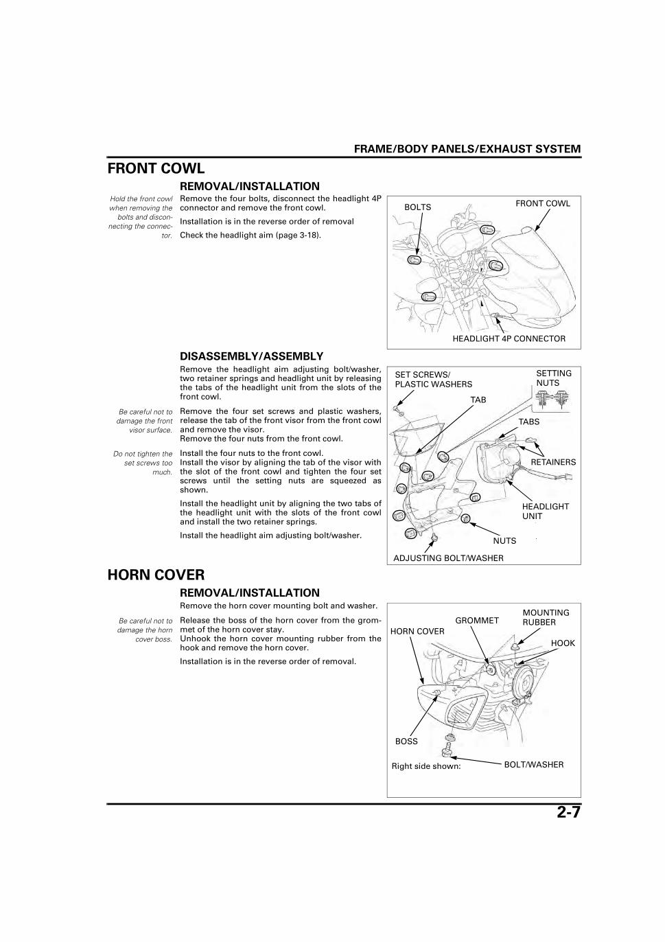
FRONT COWL
REMOVAL/INSTALLATIONHold the front cowlwhen removing the
bolts and discon-necting the connec-
tor.
Remove the four bolts, disconnect the headlight 4Pconnector and remove the front cowl.
Installation is in the reverse order of removal
Check the headlight aim (page 3-18).
DISASSEMBLY/ASSEMBLYRemove the headlight aim adjusting bolt/washer,two retainer springs and headlight unit by releasingthe tabs of the headlight unit from the slots of thefront cowl.
Remove the four set screws and plastic washers,release the tab of the front visor from the front cowland remove the visor.Remove the four nuts from the front cowl.
Install the four nuts to the front cowl.Install the visor by aligning the tab of the visor withthe slot of the front cowl and tighten the four setscrews until the setting nuts are squeezed asshown.
Install the headlight unit by aligning the two tabs ofthe headlight unit with the slots of the front cowland install the two retainer springs.
Install the headlight aim adjusting bolt/washer.
HORN COVER
REMOVAL/INSTALLATIONRemove the horn cover mounting bolt and washer.
Release the boss of the horn cover from the grom-met of the horn cover stay.Unhook the horn cover mounting rubber from thehook and remove the horn cover.
Installation is in the reverse order of removal.
BOLTS
HEADLIGHT 4P CONNECTOR
FRONT COWL
Be careful not todamage the front
visor surface.
Do not tighten theset screws too
much.
SET SCREWS/PLASTIC WASHERS
HEADLIGHT UNIT
ADJUSTING BOLT/WASHER
NUTS
SETTING NUTS
TAB
TABS
RETAINERS
Be careful not todamage the horn
cover boss.HORN COVER
BOLT/WASHER
MOUNTING RUBBER
Right side shown:
GROMMET
BOSS
HOOK

FRAME/BODY PANELS/EXHAUST SYSTEM
2-8
FOOTPEG BAR
REMOVAL/INSTALLATIONRemove the exhaust pipe/muffler (page 2-8).
Remove the four footpeg bar mounting bolts andwashers.
Pull down the rear brake pedal and remove the foot-peg bar from the engine.
Install the footpeg bar, washers and mounting boltsand tighten them to the specified torque.
Install the exhaust pipe/muffler (page 2-9).
LICENSE PLATE HOLDER
REMOVAL/INSTALLATIONRemove the two bolts and the license plate holder.
Installation is in the reverse order of removal.
EXHAUST PIPE/MUFFLER
REMOVALLoosen the muffler mounting bolt/nut, then loosenthe exhaust pipe joint nuts.Remove the muffler mounting bolt/washer/nut andthe two exhaust pipe joint nuts.
Remove the exhaust pipe/muffler and the joint col-lars.Remove the gasket.
Remove the screws, grommet and the muffler pro-tector.
TORQUE: 27 N·m (2.8 kgf·m, 20 lbf·ft)
BOLTS/WASHERS
BOLTS
LICENSE PLATE HOLDER
NUT
JOINT NUTS
GASKET
SCREWS
PROTECTOREXHAUST PIPE/MUFFLER
BOLT/WASHER
GROMMET
JOINT COLLARS

FRAME/BODY PANELS/EXHAUST SYSTEM
2-9
INSTALLATIONAlways replace the
exhaust pipe gasketwith a new one
when removing theexhaust pipe from
the engine.
Install a new gasket into the exhaust port.
Set the joint collars in the exhaust port and installthe exhaust pipe/muffler.
Loosely install the exhaust pipe joint nuts.
Loosely install the muffler mounting bolt/washer/nut.
Tighten the exhaust pipe joint nuts to the specifiedtorque.
Tighten the muffler mounting nut.
GASKET
JOINT NUTS JOINT COLLARS
TORQUE: 20 N·m (2.0 kgf·m, 15 lbf·ft)
Always inspect theexhaust system forleaks after installa-
tion.
BOLT/WASHER/NUT

MEMO
3-1
3
3. MAINTENANCE
SERVICE INFORMATION ······························ 3-2
MAINTENANCE SCHEDULE ························· 3-3
FUEL LINE ······················································ 3-4
FUEL STRAINER SCREEN····························· 3-4
THROTTLE OPERATION································ 3-5
AIR CLEANER················································· 3-6
SPARK PLUG ················································· 3-7
VALVE CLEARANCE······································ 3-8
ENGINE OIL···················································· 3-9
ENGINE OIL STRAINER SCREEN ··············· 3-10
ENGINE IDLE SPEED ··································· 3-11
SECONDARY AIR SUPPLY SYSTEM·········· 3-11
DRIVE CHAIN ··············································· 3-12
BATTERY·······················································3-14
BRAKE FLUID (TYPE II, IV)···························3-14
BRAKE SHOES WEAR (TYPE I, III) ··············3-15
BRAKE SHOES/PADS WEAR (TYPE II, IV) ···················································3-16
BRAKE SYSTEM ···········································3-16
BRAKE LIGHT SWITCH ································3-18
HEADLIGHT AIM ··········································3-18
CLUTCH SYSTEM·········································3-18
SIDE STAND ·················································3-19
SUSPENSION ···············································3-19
NUTS, BOLTS, FASTENERS ························3-20
WHEELS/TIRES ············································3-20
STEERING HEAD BEARINGS ······················3-21

MAINTENANCE
3-2
MAINTENANCE
SERVICE INFORMATION
GENERAL • Place the motorcycle on level surface before starting any work.
• The exhaust contains poisonous carbon monoxide gas that may cause loss of consciousness and may lead to death.Run the engine in an open area or with an exhaust evacuation system in an enclosed area.
SPECIFICATIONS
TORQUE VALUES
TOOLS
ITEM SPECIFICATIONS
Throttle grip free play 2.0 – 6.0 mm (0.08 – 0.24 in)Spark plug Standard DPR8EA-9 (NGK)
For extended high speed riding DPR9EA-9 (NGK)Spark plug gap 0.80 – 0.90 mm (0.031 – 0.035 in)Valve clearance IN/EX 0.08 ± 0.02 mm (0.003 ± 0.001in)Engine oil capacity After draining 0.8 liter (0.8 US qt, 0.7 lmp qt)
After disassembly 1.1 liter (1.2 US qt, 1.0 lmp qt)Recommended engine oil Honda 4-stroke oil or equivalent motor oil
API service classification: SF or SGViscosity: SAE 10W-30
Idle speed 1,400 ± 100 min-1 (rpm)Drive chain slack 10 – 20 mm (0.4 – 0.8 in)Drive chain size/link 428/108Recommended brake fluid (Type II, IV) DOT 3 or DOT 4Brake lever free play (Type I, III) 10 – 20 mm (0.4 – 0.8 in)Brake pedal free play 20 – 30 mm (0.8 – 1.2 in)Clutch lever free play 10 – 20 mm (0.4 – 0.8 in)Tire size Front 80/100 – 18 M/C 47P
Rear 90/90 – 18 M/C 51PCold tire pressure Driver only Front 200 kPa (2.00 kgf/cm2, 29 psi)
Rear 225 kPa (2.25 kgf/cm2, 33 psi)Driver and passen-ger
Front 200 kPa (2.00 kgf/cm2, 29 psi)Rear 225 kPa (2.25 kgf/cm2, 33 psi)
Minimum tire tread depth (front/rear) To wear indicator
Air cleaner housing cover screw 1.8 N·m (0.2 kgf·m, 1.3 lbf·ft)Spark plug 18 N·m (1.8 kgf·m, 13 lbf·ft)Oil drain bolt 24 N·m (2.4 kgf·m, 18 lbf·ft)Oil strainer screen cap 15 N·m (1.5 kgf·m, 11 lbf·ft) Apply oil to the threads and seating surface.Valve adjusting lock nut 14 N·m (1.4 kgf·m, 10 lbf·ft) Apply oil to the threads and seating surface.Timing hole cap 6 N·m (0.6 kgf·m, 4.4 lbf·ft)Crankshaft hole cap 8 N·m (0.8 kgf·m, 5.9 lbf·ft)Master cylinder reservoir cap screw 1.5 N·m (0.2 kgf·m, 1.1 lbf·ft)Rear axle nut 59 N·m (6.0 kgf·m, 44 lbf·ft)
Valve adjusting wrench07908-KE90000

MAINTENANCE
3-3
MAINTENANCE SCHEDULEPerform the Pre-ride inspection in the Owner's Manual at each scheduled maintenance period.
I: Inspect and Clean, Adjust, Lubricate or Replace if necessary.
C: Clean. R: Replace. A: Adjust. L: Lubricate.
The following items require some mechanical knowledge. Certain items (particularly those marked * and **) may requiremore technical information and tools. Consult their authorized Honda dealer.
Honda recommends that the Honda dealer should road test the motorcycle after each periodic maintenance is carried out.
NOTES:1. At higher odometer reading, repeat at the frequency interval established here.2. Service more frequently when riding in unusually wet or dusty areas.3. Service more frequently when riding OFF-ROAD.4. Replace every 2 years. Replacement requires mechanical skill.5. Replace every 3 years or 24,000 km (15,000 mi). Replacement requires mechanical skill.
FREQUENCY WHICHEVER COMES FIRST
ODOMETER READING (NOTE 1)REFER TO
PAGEx 1,000 mi 0.6 2.5 5 7.5x 1,000 km 1 4 8 12
ITEMS NOTE MONTHS 6 12 18* FUEL LINE I I I 3-4* FUEL STRAINER SCREEN C C C 3-4* THROTTLE OPERATION I I I 3-5
AIR CLEANER NOTE 2 C C R 3-6SPARK PLUG I R I 3-7
* VALVE CLEARANCE I I I I 3-8ENGINE OIL R EVERY 3,000 km
(2000 mi) R3-9
* ENGINE OIL STRAINER SCREEN C 3-10* ENGINE IDLE SPEED I I I I 3-11* SECONDARY AIR SUPPLY SYSTEM NOTE 5 I 3-11
DRIVE CHAIN NOTE 3 EVERY 1,000 km (600 mi) I, L 3-12BATTERY EVERY 2,000 km (1250 mi) I 3-14BRAKE FLUID (TYPE II, IV) NOTE 4 I I I 3-14BRAKE SHOES WEAR (TYPE I, III) I I I 3-15BRAKE SHOES/PADS WEAR (TYPE II, IV) I I I 3-16BRAKE SYSTEM I I I I 3-16
* BRAKE LIGHT SWITCH I I I 3-18* HEADLIGHT AIM I I I 3-18
CLUTCH SYSTEM I I I I 3-18SIDE STAND I I I 3-19
* SUSPENSION I I I 3-19* NUTS, BOLTS, FASTENERS NOTE 3 I I 3-20
** WHEELS/TIRES I I I 3-20** STEERING HEAD BEARINGS I I 3-21
* Should be serviced by an authorized Honda dealer, unless the owner has proper tools and service data and is mechanically qualified. Refer to the official Honda shop manual.
** In the interest of safety, we recommended these items be serviced only by an authorized Honda dealer.

MAINTENANCE
3-4
FUEL LINEInspect the fuel line for crack, damage or leak.
Clean or replace if necessary.
If the fuel flow is restricted, inspect the fuel line andfuel strainer for blockage.
FUEL STRAINER SCREENTurn the fuel valve "OFF".Remove the fuel strainer cup and drain the contentsof the cup into a suitable container.
Remove the O-ring and fuel strainer screen.Wash the fuel strainer screen and cup in clean non-flammable high flash point solvent.
Install the fuel strainer screen, new O-ring and fuelstrainer cup to the fuel valve body, making sure thatthe O-ring is in place.Tighten the fuel strainer cup securely.
Turn the fuel valve "ON" and be sure there are nofuel leaks.
FUEL LINE
FUEL VALVE
FUEL STRAINER CUP
FUEL VALVE
O-RINGFUEL STRAINER CUP
FUEL STRAINER SCREEN

MAINTENANCE
3-5
THROTTLE OPERATIONCheck the throttle grip for smooth operation.Check that the throttle opens and automaticallycloses in all steering positions.
If the throttle grip does not return properly, checkthe throttle cable routing.
Check for any deterioration or damage to the throt-tle cable.
If the throttle grip still does not return properly,lubricate or replace the throttle cables.
With the engine idling, turn the handlebar all theway to the right and left to ensure that the idlespeed does not change.If idle speed increase, check the throttle grip freeplay and the throttle cable connection.
Measure the free play at the throttle grip flange.
Slide the dust cover.Loosen the lock nut and turn the adjuster asrequired.
After adjustment, tighten the lock nut and repositionthe dust cover.
Recheck the throttle operation in all steering posi-tions.
FREE PLAY: 2.0 – 6.0 mm (0.08 – 0.24 in)
2.0 – 6.0 mm (0.08 – 0.24 in)
ADJUSTERDUST COVER
LOCK NUT

MAINTENANCE
3-6
AIR CLEANERRemove the right side cover (page 2-3).
Disconnect the crankcase breather hose.
Loosen the air cleaner connecting hose band screw.Remove the screws and the air cleaner housingcover.
Remove the screw and the air cleaner element.
Replace the element in accordance with the mainte-nance schedule (page 3-3).
Inspect the element and replace if it is excessivelydirty or damaged.
If reusable, clean the element using compressed airfrom the carburetor side from 30 mm (1.1 in) away.
Blow the element for one minute along the fold linewhile rotating it.
Then, blow the element for 30 seconds from theoutside along the fold line while rotating it.
Blow off the remaining dust from the carburetorside from 30 mm (1.1 in) away for 30 seconds alongthe fold line while rotating it.
Install the removed parts in the reverse order ofremoval.
SCREWS
BAND SCREW BREATHER HOSE
AIR CLEANER HOUSING COVER
AIR CLEANER ELEMENT SCREW
30 mm (1.1 in)
ROTATE
TORQUE: AIR CLEANER HOUSING COVER SCREW
1.8 N·m (0.2 kgf·m, 1.3 lbf·ft)
ROTATE
30 mm (1.1 in)

MAINTENANCE
3-7
SPARK PLUGClean around the
spark plug basewith compressedair before remov-
ing the plug, and besure that no debrisis allowed to enter
the combustionchamber.
Disconnect the spark plug cap and remove the sparkplug.
Inspect or replace as described in the maintenanceschedule (page 3-3).
Check the following and replace if necessary.
• Insulator for damage • Electrodes for wear • Burning condition, coloration;
– Dark to light brown indicates good condition.– Excessive lightness indicates malfunctioning
ignition system or lean mixture.– Wet or black sooty deposit indicates over-rich
mixture.
If the electrode is contaminated with carbon depos-its, clean the electrode using a spark plug cleaner.
Measure the spark plug gap between the center andside electrodes with a feeler gauge of a wire type.If necessary, adjust the gap by bending the sideelectrode carefully.
Do not overtightenthe spark plug.
Install and hand tighten the spark plug to the cylin-der head, then tighten the spark plug to the speci-fied torque.
Connect the spark plug cap.
SPARK PLUG CAP SPARK PLUG
RECOMMENDED SPARK PLUG:
Standard: DPR8EA-9 (NGK)
For extended high speed riding: DPR9EA-9 (NGK)
CENTER ELECTRODE
INSULATORSIDE ELECTRODE
SPARK PLUG GAP: 0.80 – 0.90 mm (0.031 – 0.035 in)
0.80 – 0.90 mm (0.031 – 0.035 in)
TORQUE: 18 N·m (1.8 kgf·m, 13 lbf·ft)
SPARK PLUG SPARK PLUG CAP

MAINTENANCE
3-8
VALVE CLEARANCERemove the cylinder head cover (page 7-7).
Remove the crankshaft hole cap and timing holecap.
Rotate the crankshaft counterclockwise and alignthe index line of the "T" mark on the flywheel withthe index notch on the left crankcase cover.
Make sure that the piston is at TDC (Top Dead Cen-ter) on the compression stroke (The rocker armsshould be loose).
If the rocker arms are tight, rotate the crankshaftcounterclockwise 360°(1 full turn) and realign theindex line of the "T" mark with the index notch.
When checking theclearance, slide the
feeler gauge fromthe center toward
the outside.
Check the valve clearance by inserting the feelergauge between the valve adjusting screw and thevalve stem.
If the valve clearance is incorrect, loosen the valveadjusting screw lock nut and adjust the valve clear-ance by turning the adjusting screw until there is aslight drag on the feeler gauge.
Apply clean engine oil to the lock nut.Hold the adjusting screw and tighten the lock nut tothe specified torque.
Recheck the valve clearance.
Install the cylinder head cover (page 7-8).
Apply clean engine oil to the new O-rings.Install the O-rings to the crankshaft hole cap andtiming hole cap.
Install and tighten the crankshaft hole cap and tim-ing hole cap to the specified torque.
Inspect and adjustthe valve clearancewhile the engine is
cold (below 35°C/95°F).
CRANKSHAFT HOLE CAP
TIMING HOLE CAP
INDEX LINEINDEX NOTCH
"T" MARK
VALVE CLEARANCE:
IN/EX: 0.08 ± 0.02 mm (0.003 ± 0.001 in)
TOOLS:
Valve adjusting wrench 07908-KE90000
TORQUE: 14 N·m (1.4 kgf·m, 10 lbf·ft)
TORQUE:
Timing hole cap: 6 N·m (0.6 kgf·m, 4.4 lbf·ft)
Crankshaft hole cap: 8 N·m (0.8 kgf·m, 5.9 lbf·ft)
FEELER GAUGE
LOCK NUT
ADJUSTING WRENCH
ADJUSTING SCREW
CRANKSHAFT HOLE CAP
TIMING HOLE CAPO-RINGS

MAINTENANCE
3-9
ENGINE OILLEVEL CHECKClean around the oil filler cap/dipstick and nearbysurface.Start the engine and let it idle for 3 – 5 minutes.Stop the engine and wait 2 – 3 minutes.Support the motorcycle upright on a level surface.
Remove the filler cap/dipstick and wipe the oil witha clean cloth.Insert the dipstick without screwing it in, remove itand check the oil level
The level should be between the "UPPER" and"LOWER" level lines of the oil filler cap/dipstick.
If the oil level is below or near the lower level lineon the dipstick, add the recommended oil to theupper level line from the oil filler hole.
Other viscositiesshown in the chartmay be used when
the average tem-perature in your
riding area is withinthe indicated range.
Coat a new O-ring with clean engine oil and installthe oil filler cap/dipstick.
FILLER CAP/DIPSTICK
UPPER
FILLER CAP/DIPSTICK
LOWER
RECOMMENDED ENGINE OIL:
Honda 4-stroke oil or equivalent motor oilAPI service classification: SF or SGViscosity: SAE 10W-30
OIL VISCOSITIES
FILLER CAP/DIPSTICK
O-RING

MAINTENANCE
3-10
OIL CHANGEDrain the engine oilwhile the engine iswarm. This ensurecomplete and rapid
draining.
Place the motorcycle on its center stand.
Remove the oil filler cap/dipstick.
Place an oil pan under the engine to collect the oil,then remove the oil drain bolt and sealing washer.
After draining the oil completely, install the newsealing washer and oil drain bolt.
Tighten the oil drain bolt to the specified torque.
Fill the crankcase with the recommended engine oil.
Install the oil filler cap/dipstick.
Check the oil level (page 3-9).
Make sure that there are no oil leaks.
ENGINE OIL STRAINER SCREEN
OIL CHANGE/STRAINER CLEANINGDrain the engine oil (page 3-10).
Remove the oil strainer screen cap, O-ring, springand oil strainer screen.
Check the oil strainer screen for clogs or damage.
Install the oil strainer screen and spring into thecrankcase as shown.
Coat a new O-ring with clean engine oil.
Apply clean engine oil to the oil strainer screen capthreads and seating surface.
Install and tighten the oil strainer screen cap with anew O-ring.
Fill the crankcase with recommended engine oil.
Check the engine oil level (page 3-9).
Make sure that there are no oil leaks.
FILLER CAP/DIPSTICK
TORQUE: 24 N·m (2.4 kgf·m, 18 lbf·ft)
If the maintenancefor the engine oilstrainer screen is
scheduled, per-form it before fill-ing the crankcase
with engine oil.
ENGINE OIL CAPACITY:
After draining: 0.8 liter (0.8 US qt, 0.7 lmp qt)
After disassembly: 1.1 liter (1.2 US qt, 1.0 lmp qt)
SEALING WASHERDRAIN BOLT/
TORQUE: 15 N·m (1.5 kgf·m, 11 lbf·ft)SPRINGOIL STRAINER SCREEN
O-RING OIL STRAINER CAP

MAINTENANCE
3-11
ENGINE IDLE SPEED • Inspect and adjust the idle speed after all other
engine maintenance items have been performedand are within specifications.
• Engine must be warm for accurate adjustment.Ten minutes of stop-and-go riding is sufficient.
Warm the engine, shift the transmission into neutraland support the motorcycle upright on a level sur-face.
Connect a tachometer and check the idle speed.
If the adjustment is necessary, turn the throttle stopscrew as required.
SECONDARY AIR SUPPLY SYSTEM • The secondary air supply system introduces fil-
tered air into exhaust gases in the exhaust port.The secondary air is drawn into the exhaust portwhenever there is negative pressure pulse in theexhaust system. This charged secondary air pro-motes burning of the unburned exhaust gasesand changes a considerable amount of hydrocar-bons and carbon monoxide into relatively harm-less carbon dioxide and water.
Remove the fuel tank (page 2-4).
Check the air cleaner sub filter for damage andreplace if necessary (page 5-22).Check the hoses for deterioration, damage or looseconnections.
If the hoses show any signs of heat damage or/andshow carbon deposit, inspect the PAIR check valve(page 5-23).
If the hoses showany signs of heatdamage, inspectthe PAIR check
valve for damage((page 5-23).
Check the following hoses for deterioration, dam-age, or loose connection.Make sure that the hoses are not cracked.
– Air cleaner sub filter-to-open air hose.– Air cleaner sub filter-to-PAIR control valve hose.– Air supply pipe-to-PAIR control valve hose.
IDLE SPEED: 1,400 ± 100 min-1 (rpm)
THROTTLE STOP SCREW
FILTER
SUB FILTER-to- OPEN AIR HOSE
SUB FILTER-to-PAIR CONTROL VALVE HOSE
SUB FILTER-to-PAIR CONTROL VALVE HOSE
AIR SUPPLY PIPE-to-PAIR CONTROL VALVE HOSE

MAINTENANCE
3-12
Check the vacuum hose between the PAIR controlvalve and carburetor insulator for deterioration,damage or loose connections.Make sure that the hose is not kinked, pinched orcracked.
Install the fuel tank (page 2-4).
DRIVE CHAIN
DRIVE CHAIN SLACK INSPECTION
Excessive chain slack, 50 mm (2.0 in) or more, maydamage the frame.
Turn off the ignition switch, place the motorcycle onits center stand and shift the transmission into neu-tral.Check the slack in the drive chain lower run midwaybetween the sprockets.
ADJUSTMENTLoosen the rear axle nut.Loosen the both lock nuts.Turn both adjusting bolts until the correct drivechain slack is obtained.Make sure that the index marks on the both adjust-ers are aligned with the rear edges of the swingarm.
Tighten the rear axle nut to the specified torque.
Tighten the both lock nuts.
Recheck the drive chain slack and free wheel rota-tion.
Check the rear brake pedal free play (page 3-17).
VACUUM HOSE
Never inspect oradjust the drivechain while the
engine is running.
CHAIN SLACK: 10 – 20 mm (0.4 – 0.8 in)
10 – 20 mm (0.4 – 0.8 in)
TORQUE: 59 N·m (6.0 kgf·m, 44 lbf·ft)
REAR AXLE NUT
LOCK NUT
ADJUSTING BOLT

MAINTENANCE
3-13
REMOVAL/INSTALLATIONRemove the left crankcase rear cover (page 6-4).
Carefully remove the retaining clip with pliers.Remove the master link, link plate and drive chain.
Install the drive chain onto the sprockets.Install the master link and link plate.Install the retaining clip with its open end oppositedirection of the chain travel.
Install the left crankcase rear cover (page 6-5).
CLEANING AND LUBRICATIONIf the drive chain is extremely dirty, it should beremoved and cleaned prior to lubrication.
Remove the drive chain (page 3-13).
Clean the chain with non-flammable or high flashpoint solvent and wipe it dry.Make sure that the chain is completely dry beforelubricating.Lubricate the drive chain with # 80 – 90 gear oil ordrive chain lubricant. Wipe off the excess oil orchain lubricant.
Inspect the drive chain for possible damage or wear.
Replace any chain that has damaged rollers, loosefitting links, or otherwise appears unserviceable.
Measure the drive chain length with the chain heldso that all the links are straight.
Inspect the drive and driven sprocket teeth for wearor damage, replace if necessary.Never use a new drive chain on worn sprockets.Both chain and sprockets must be in good condi-tion, or the new replacement chain will wear rap-idly.
Install the drive chain (page 3-13).
LINK PLATE
RETAINING CLIP
MASTER LINK
CLEAN
NON-FLAMMABLE OR HIGH FLASH POINT SOLVENT
WIPE AND DRY
LUBRICATE
# 80 – 90 GEAR OIL OR DRIVE CHAIN LUBRICANT
DRIVE CHAIN LENGTH (41pins/40 links)
STANDARD: 508 mm (20.0 in)
SERVICE LIMIT: 518 mm (20.4 in)
41PINS/40LINKS
DAMAGE
WEAR
NORMAL

MAINTENANCE
3-14
BATTERYRemove the battery (page 15-6).
Inspect the electrolyte level.
When the electrolyte level nears the lower level,remove the filler caps and add distilled water to theupper level line.
After filling, install each filler cap firmly.
Install the battery (page 15-6).
Make sure that the battery breather hose is correctlypositioned, not kinked, trapped or bent in such away as to obstruct the passage of the air.
BRAKE FLUID (TYPE II, IV) • Do not mix different types of fluid, as they are
not compatible with each other. • Do not allow foreign material to enter the system
when filling the reservoir.
Spilled fluid can damage painted, plastic or rubberparts. Place a rag over these parts whenever thesystem is serviced.
Turn the handlebar so the reservoir is level andcheck the front brake fluid reservoir level throughthe sight glass.
When the fluid level is low, check the brake pads forwear (page 3-16).A low fluid level may be due to worn brake pads. If the brake pads are worn, the caliper pistons arepushed out, and this causes a low reservoir level. If the brake pads are not worn and the fluid level islow, check entire system for leaks (page 3-17).
If the level is near the lower level line, remove thereservoir cap, set plate and diaphragm, and fill thereservoir DOT 3 or DOT 4 brake fluid from a sealedcontainer to the casting ledge.
Add only distilledwater. Tap water
will shorten the lifeof the battery.
After connectingthe battery termi-
nals, lightly coat theterminals withclean grease.
FILLER CAPS
SIGHT GLASS LOWER LEVEL LINE
CASTING LEDGE

MAINTENANCE
3-15
Install the diaphragm, set plate and reservoir cap,and tighten the cap screws to the specified torque.
BRAKE SHOES WEAR (TYPE I, III)
FRONT BRAKE SHOESCheck the wear indicator position when the brakelever is applied.
If the arrow on the brake arm aligns with the refer-ence mark " " on the brake panel, inspect the brakedrum (page 12-20).
Replace the brake shoes (page 12-20) if the drumI.D. is within the service limit.
REAR BRAKE SHOESCheck the wear indicator position when the brakepedal is applied.
If the arrow on the brake arm aligns with the refer-ence mark " " on the brake panel, inspect the brakedrum (page 13-13).
Replace the brake shoes (page 13-13) if the drumI.D. is within the service limit.
TORQUE: 1.5 N·m (0.2 kgf·m, 1.1 lbf·ft)SET PLATE
DIAPHRAGM
RESERVOIR CAPSCREWS
ARROW MARK
ARROW
MARK
MAINTENANCE
3-16
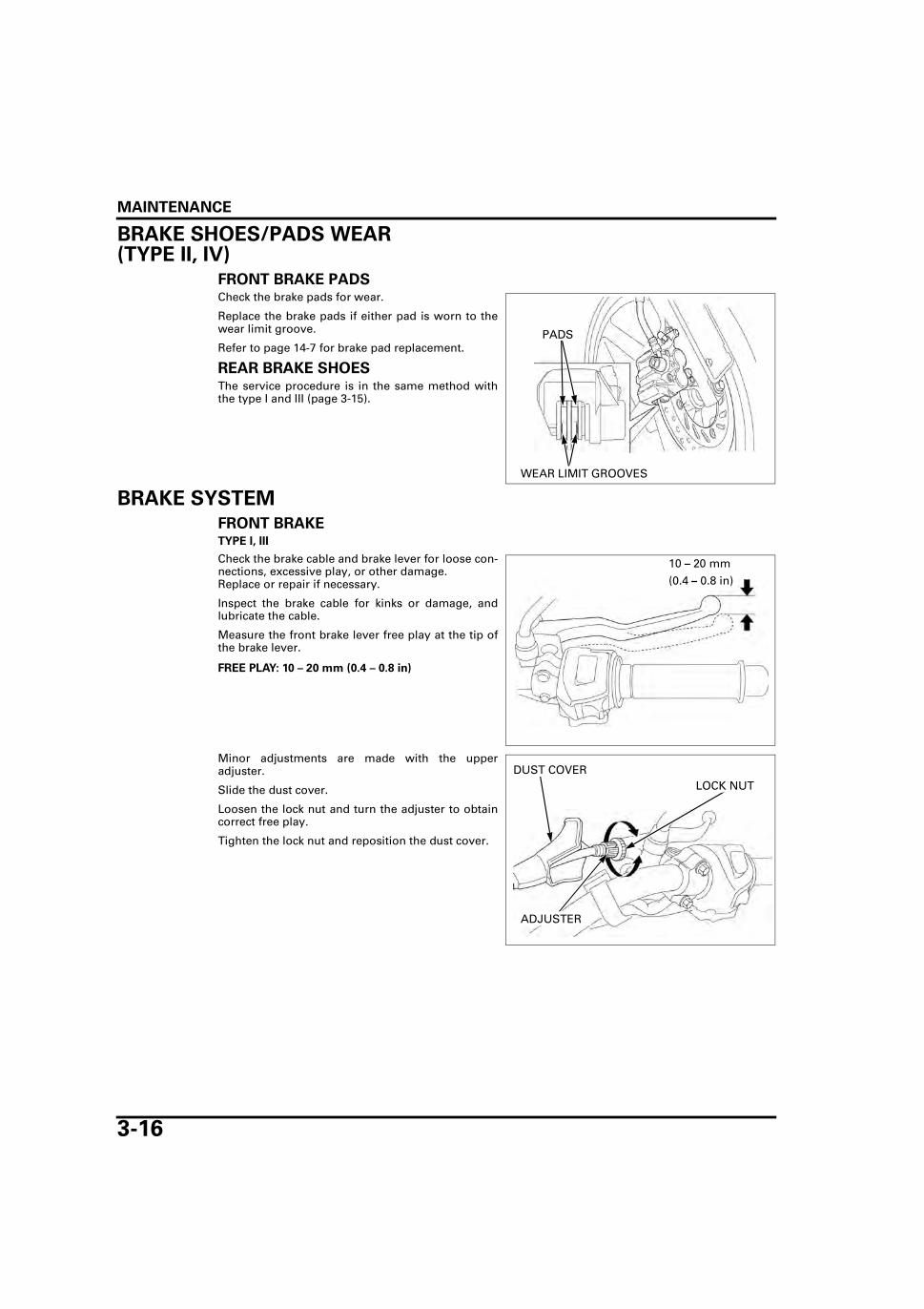
BRAKE SHOES/PADS WEAR (TYPE II, IV)
FRONT BRAKE PADSCheck the brake pads for wear.
Replace the brake pads if either pad is worn to thewear limit groove.
Refer to page 14-7 for brake pad replacement.
REAR BRAKE SHOESThe service procedure is in the same method withthe type I and III (page 3-15).
BRAKE SYSTEM
FRONT BRAKETYPE I, III
Check the brake cable and brake lever for loose con-nections, excessive play, or other damage.Replace or repair if necessary.
Inspect the brake cable for kinks or damage, andlubricate the cable.
Measure the front brake lever free play at the tip ofthe brake lever.
Minor adjustments are made with the upperadjuster.
Slide the dust cover.
Loosen the lock nut and turn the adjuster to obtaincorrect free play.
Tighten the lock nut and reposition the dust cover.
PADS
WEAR LIMIT GROOVES
FREE PLAY: 10 – 20 mm (0.4 – 0.8 in)
10 – 20 mm
(0.4 – 0.8 in)
LOCK NUT
ADJUSTER
DUST COVER

MAINTENANCE
3-17
Make sure the cut-out of the adjustingnut is seated on the
brake arm pin.
Major adjustments are made with the loweradjuster.
Turn the adjusting nut to obtain correct free play.
Recheck the brake lever free play (page 3-16).
TYPE II, IV
Inspect the brake hose and fittings for deterioration,cracks and signs of leakage.Tighten any loose fittings.Replace hoses and fittings as required.
Firmly apply the brake lever, and check that no airhas entered the system.If the lever feels soft or spongy when operated,bleed the air from the system.
Refer to page 14-5 for brake bleeding procedures.
REAR BRAKECheck the brake pedal and brake rod for loose con-nections, excessive play, or other damage.Replace or repair if necessary.
Measure the rear brake pedal free play.
Make sure the cut-out of the adjustingnut is seated on the
brake arm pin.
Adjust the rear brake pedal free play by turning theadjusting nut.
Recheck the free play, then check and adjust thebrake light switch (page 3-18).
ADJUSTING NUT BRAKE ARM PIN
FITTING
FITTING
FREE PLAY: 20 – 30 mm (0.8 – 1.2 in)
20 – 30 mm
(0.8 – 1.2 in)
ADJUSTING NUT BRAKE ARM PIN

MAINTENANCE
3-18
BRAKE LIGHT SWITCHThe front brake
light switch doesnot require adjust-
ment.
Adjust the rear brake light switch so that the brakelight comes on just prior to the brake actually beingengaged.
If the light fails to come on properly, adjust thebrake light switch by holding the switch body andturning the adjuster.
HEADLIGHT AIMAdjust the headlight
beam as specifiedby local laws and
regulations.
Place the motorcycle on a level surface.
Adjust the headlight beam vertically by looseningthe adjusting bolt and moving the headlight unit.
Tighten the adjusting bolt after adjustment.
CLUTCH SYSTEMInspect the clutch cable for kinks or damage, andlubricate the cable if necessary.
Measure the clutch lever free play at the tip of theclutch lever.
Minor adjustments are made with the upperadjuster at the clutch lever.
Slide the dust cover, loosen the lock nut and turnthe adjuster to obtain the correct free play.
Tighten the lock nut and reposition the dust cover.
The adjuster may be damaged if it is positioned toofar out, leaving minimal thread engagement.
If the adjuster is threaded out near the limit and thecorrect free play cannot be obtained, turn theadjuster all the way in and back out one turn.
Tighten the lock nut and make major adjustments asfollows.
REAR BRAKE LIGHT SWITCH
ADJUSTER
ADJUSTING BOLT
FREE PLAY: 10 – 20 mm (0.4 – 0.8 in)
10 – 20 mm (0.4 – 0.8 in)
ADJUSTERLOCK NUT
DUST COVER

MAINTENANCE
3-19
Major adjustments are made with the lower adjust-ing nut at the engine.
Loosen the lock nut and turn the adjusting nut.After adjustment is complete, tighten the lock nutwhile holding the adjusting nut.
Check the clutch operation.
If the correct free play cannot be obtained, or theclutch slips during the test ride, disassemble andinspect the clutch (page 9-7).
SIDE STANDCheck the side stand spring for damage or loss oftension.Check the side stand operation for freedom ofmovement and lubricate the side stand pivot if nec-essary.
Check that the side stand pivot bolt and lock nut aretightened.
SUSPENSION
FRONT Check the action of the forks by applying the frontbrake and compressing front suspension severaltimes.Check the entire assembly for signs of leaks, dam-age or loose fasteners.Replace damaged components which cannot berepaired.Tighten all nuts and bolts.
Refer to page 12-24 for fork service.
REARCheck the action of the shock absorber by com-pressing it several times.Check the entire shock absorber assembly for signsof leaks, damage or loose fasteners.Replace damaged components which cannot berepaired.Tighten all nuts and bolts.
Refer to page 13-20 for shock absorber service.
LOCK NUT
ADJUSTING NUT

MAINTENANCE
3-20
Raise the rear wheel off the ground and support themotorcycle securely.
Check for worn swingarm by grabbing theswingarm and attempting to move the wheel side toside.
NUTS, BOLTS, FASTENERSCheck that all chassis nuts and bolts are tightened totheir correct torque values (page 1-10).Check that all cotter pins, safety clips, hose clampsand cable stays are in place and properly secured.
WHEELS/TIRESCheck for worn front wheel bearings by grabbingthe front wheel and attempting to move the wheelside to side.Replace the front wheel bearings if any looseness isnoted (Type I, III: page 12-13 or Type II, IV: page 12-16).
Making sure that the fork is not allowed to move,raise the front wheel and check for play. Turn the wheel and check that it rotates smoothlywith no unusual noises.
If any abnormal conditions are suspected, inspectthe front wheel bearings (Type I, III: page 12-12 orType II, IV: page 12-15).
Support the motorcycle securely and raise the rearwheel off the ground.
Check for worn rear wheel bearings by grabbing therear wheel and attempting to move the wheel sideto side.
Check for play in either the wheel or the swingarmpivot. Turn the wheel and check that it rotates smoothlywith no unusual noises.
If any abnormal conditions are suspected, check therear wheel bearings (page 13-7).
As the swingarmpivot is included inthis check, be sure
to confirm the loca-tion of the play; i.e.
from the wheelbearings or the
swingarm pivot.

MAINTENANCE
3-21
Check the tire pressure when the tires are cold.
RECOMMENDED TIRE PRESSURE AND TIRE SIZE:
Check the tires for cuts, embedded nails, or otherdamage.Check the front wheel (Type I, III: page 12-12 or TypeII, IV: page 12-15) and rear wheel (page 13-7) fortrueness.
Replace the tires when the wear indicator appearson the tire.
STEERING HEAD BEARINGSRaise the front wheel off the ground by placing awork stand or box under the engine.
Check that the handlebar moves freely from side toside. Make sure the control cables do not interferewith the handlebar rotation.If the handlebar moves unevenly, binds, or has ver-tical movement, inspect the steering head bearings(page 12-31).
FRONT REAR
Tire pressurekPa (kgf/cm2, psi)
Driver only 200(2.00, 29)
225 (2.25, 33)
Driver and passenger
200 (2.00, 29)
225 (2.25, 33)
Tire size 80/100-18M/C (47P)
90/90-18M/C (51P)
PRESSURE GAUGE
MINIMUM TIRE TREAD DEPTH:
FRONT: To wear indicator
REAR: To wear indicator

MEMO

4-1
4
4. LUBRICATION SYSTEM
LUBRICATION SYSTEM DIAGRAM ············· 4-2
SERVICE INFORMATION ······························ 4-3
TROUBLESHOOTING ···································· 4-3
OIL FILTER ROTOR CLEANING ·····················4-4
OIL PUMP························································4-5

LUBRICATION SYSTEM
4-2
LUBRICATION SYSTEM
LUBRICATION SYSTEM DIAGRAM
PUSH ROD
OIL STRAINER SCREEN
OIL PUMP
ROCKER ARM
OIL FILTER
MAINSHAFT
CAMSHAFT
PISTON
COUNTERSHAFT
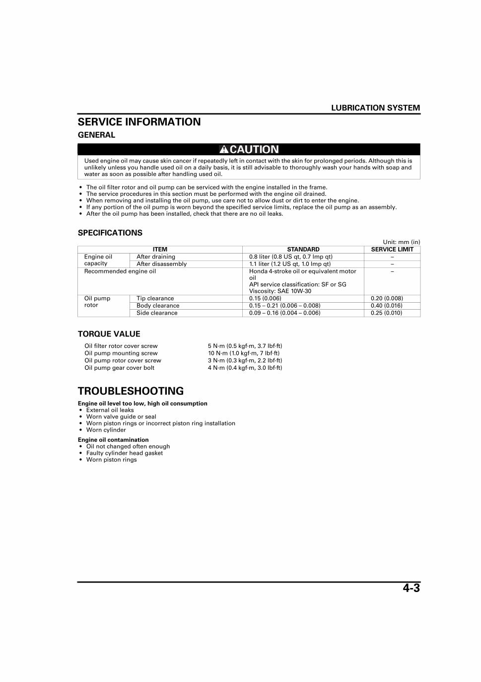
LUBRICATION SYSTEM
4-3
SERVICE INFORMATION
GENERAL
• The oil filter rotor and oil pump can be serviced with the engine installed in the frame. • The service procedures in this section must be performed with the engine oil drained. • When removing and installing the oil pump, use care not to allow dust or dirt to enter the engine. • If any portion of the oil pump is worn beyond the specified service limits, replace the oil pump as an assembly. • After the oil pump has been installed, check that there are no oil leaks.
SPECIFICATIONSUnit: mm (in)
TORQUE VALUE
TROUBLESHOOTINGEngine oil level too low, high oil consumption • External oil leaks • Worn valve guide or seal • Worn piston rings or incorrect piston ring installation • Worn cylinder
Engine oil contamination • Oil not changed often enough • Faulty cylinder head gasket • Worn piston rings
Used engine oil may cause skin cancer if repeatedly left in contact with the skin for prolonged periods. Although this is unlikely unless you handle used oil on a daily basis, it is still advisable to thoroughly wash your hands with soap and water as soon as possible after handling used oil.
ITEM STANDARD SERVICE LIMIT
Engine oil capacity
After draining 0.8 liter (0.8 US qt, 0.7 lmp qt) –After disassembly 1.1 liter (1.2 US qt, 1.0 lmp qt) –
Recommended engine oil Honda 4-stroke oil or equivalent motor oilAPI service classification: SF or SG Viscosity: SAE 10W-30
–
Oil pump rotor
Tip clearance 0.15 (0.006) 0.20 (0.008)Body clearance 0.15 – 0.21 (0.006 – 0.008) 0.40 (0.016)Side clearance 0.09 – 0.16 (0.004 – 0.006) 0.25 (0.010)
Oil filter rotor cover screw 5 N·m (0.5 kgf·m, 3.7 lbf·ft)Oil pump mounting screw 10 N·m (1.0 kgf·m, 7 lbf·ft)Oil pump rotor cover screw 3 N·m (0.3 kgf·m, 2.2 lbf·ft)Oil pump gear cover bolt 4 N·m (0.4 kgf·m, 3.0 lbf·ft)

LUBRICATION SYSTEM
4-4
OIL FILTER ROTOR CLEANINGRemove the right crankcase cover (page 9-5).
Remove the three screws, oil filter rotor cover andgasket.
Do not use com-pressed air.
Clean the oil filter rotor cover and inside of the oilfilter rotor using a clean lint-free cloth.
Apply clean engine oil to the oil filter rotor inner sur-face.
Install a new gasket to the oil filter rotor cover.
Install the oil filter rotor cover to the oil filter rotor.
Install and tighten three screws to the specifiedtorque.
Install the right crankcase cover (page 9-14).
COVER/GASKET
SCREWS
FILTER ROTOR
COVER/ GASKET FILTER ROTOR
TORQUE: 5 N·m (0.5 kgf·m, 3.7 lbf·ft)
SCREWS

LUBRICATION SYSTEM
4-5
OIL PUMP
REMOVALDrain the engine oil (page 3-10).Remove the right crankcase cover (page 9-5).
Turn the crankshaft clockwise and align the holes inthe oil pump drive gear with oil pump mountingscrews.
Remove the two mounting screws and oil pump.
Remove the O-rings from the crankcase grooves.
INSPECTION • Measure at several places and use the largest
reading to compare to the service limit. • If any portion of the oil pump is worn beyond the
specified service limits, replace the oil pump andoil pump cover as an assembly.
Remove the rotor cover (page 4-6).
Measure the tip clearance between the inner andouter rotors.
MOUNTING SCREWS
OIL PUMP
O-RINGS
SERVICE LIMIT: 0.20 mm (0.008 in)

LUBRICATION SYSTEM
4-6
Measure the body clearance between the outerrotor and pump body.
Measure the side clearance using a straight edgeand feeler gauge.
DISASSEMBLYIf any portion of the
oil pump is wornbeyond the servicelimit, replace the oilpump as an assem-
bly.
Remove the two screws and rotor cover.
Remove the following:
– Inner and outer rotors
SERVICE LIMIT: 0.40 mm (0.016 in)
SERVICE LIMIT: 0.25 mm (0.010 in)
SCREWS
ROTOR COVER
INNER ROTOR
OUTER ROTOR

LUBRICATION SYSTEM
4-7
– Two bolts– Gear cover
– Rotor shaft– Pump gear
Check the pump gear and rotor shaft for wear ordamage.
ASSEMBLY
BOLTS
GEAR COVER
PUMP GEAR
ROTOR SHAFT
OUTER ROTOR
GEAR COVER
ROTOR SHAFT
PUMP GEAR
OUTER ROTOR
INNER ROTOR
ROTOR COVER
PUMP BODY
BOLTS
SCREWS
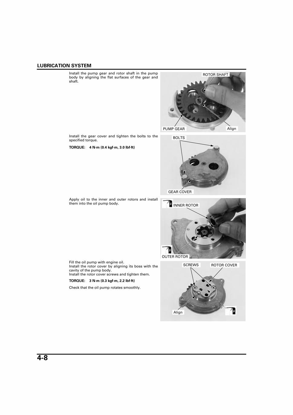
LUBRICATION SYSTEM
4-8
Install the pump gear and rotor shaft in the pumpbody by aligning the flat surfaces of the gear andshaft.
Install the gear cover and tighten the bolts to thespecified torque.
Apply oil to the inner and outer rotors and installthem into the oil pump body.
Fill the oil pump with engine oil.Install the rotor cover by aligning its boss with thecavity of the pump body.Install the rotor cover screws and tighten them.
Check that the oil pump rotates smoothly.
PUMP GEAR
ROTOR SHAFT
Align
TORQUE: 4 N·m (0.4 kgf·m, 3.0 lbf·ft)
BOLTS
GEAR COVER
OUTER ROTOR
INNER ROTOR
TORQUE: 3 N·m (0.3 kgf·m, 2.2 lbf·ft)
SCREWS ROTOR COVER
Align

LUBRICATION SYSTEM
4-9
INSTALLATIONCoat new O-rings with oil and install them into thecrankcase grooves.
Align the holes of the oil pump drive gear with oilpump mounting screw holes.Install the oil pump onto the crankcase and tightenthe mounting screws.
Install the right crankcase cover (page 9-14).
After installation, fill the crankcase with recom-mended oil (page 3-10).
Check that there are no oil leaks.
O-RINGS
TORQUE: 10 N·m (1.0 kgf·m, 7 lbf·ft)
MOUNTING SCREWS
OIL PUMP

MEMO

5-1
5
5. FUEL SYSTEM
SYSTEM COMPONENTS ······························ 5-2
SERVICE INFORMATION ······························ 5-3
TROUBLESHOOTING ···································· 5-4
AIR CLEANER HOUSING ······························ 5-5
STORAGE TANK············································ 5-8
THROTTLE VALVE········································· 5-8
CARBURETOR REMOVAL··························· 5-10
CHOKE LEVER ············································· 5-11
AIR CUT-OFF VALVE··································· 5-13
CARBURETOR DISASSEMBLY····················5-14
CARBURETOR BODY CLEANING················5-15
CARBURETOR ASSEMBLY··························5-16
CARBURETOR INSTALLATION ···················5-19
INSULATOR ··················································5-20
PILOT SCREW ADJUSTMENT·····················5-21
SECONDARY AIR SUPPLY SYSTEM ··········5-22
FUEL STRAINER ···········································5-26

FUEL SYSTEM
5-2
FUEL SYSTEM
SYSTEM COMPONENTS
1.8 N·m (0.2 kgf·m, 1.3 lbf·ft)
1.8 N·m (0.2 kgf·m, 1.3 lbf·ft)

FUEL SYSTEM
5-3
SERVICE INFORMATIONGENERAL • Work in a well ventilated area. Smoking or allowing flames or sparks in the work area or where gasoline is stored can
cause a fire or explosion. • Bending or twisting the control cable will impair smooth operation and could cause the cable to stick or bind, resulting
in loss of vehicle control. • Before removing the carburetor, place an approved gasoline container under the carburetor drain hose, loosen the
drain screw and drain the carburetor. • After removing the carburetor, cover the intake port of the cylinder head with a shop towel or pieces of tape to prevent
any foreign material from dropping into the engine. • When disassembling the fuel system parts, note the locations of the O-rings. Replace them with new ones on reassem-
bly. • If the vehicle is to be stored for more than one month, drain the float chamber. Fuel left in the float chamber may cause
clogged jets, resulting in hard starting or poor driveability.
SPECIFICATIONS
TORQUE VALUES
TOOL
ITEM SPECIFICATIONS
Carburetor identification number PDCBEMain jet #95Slow jet #38Pilot screw initial/final opening See page 5-21Idle speed 1,400 ± 100 min-1 (rpm)Throttle grip free play 2.0 – 6.0 mm (0.08 – 0.24 in)PAIR control valve specified vacuum 60 kpa (450 mm Hg)Float level 14.0 mm (0.55 in)
Choke lever screw 2.1 N·m (0.2 kgf·m, 1.5 lbf·ft)Carburetor drain screw 1.5 N·m (0.2 kgf·m, 1.1 lbf·ft)Slow jet 1.8 N·m (0.2 kgf·m, 1.3 lbf·ft)Needle jet holder 2.5 N·m (0.3 kgf·m, 1.8 lbf·ft)Main jet 2.1 N·m (0.2 kgf·m, 1.5 lbf·ft)Float chamber screw 2.1 N·m (0.2 kgf·m, 1.5 lbf·ft)Air cut-off valve cover screw 2.1 N·m (0.2 kgf·m, 1.5 lbf·ft)PAIR control valve mounting nut 9 N·m (0.9 kgf·m, 6.6 lbf·ft)Air cleaner housing cover screw 1.8 N·m (0.2 kgf·m, 1.3 lbf·ft)Tool box lid screw 1.8 N·m (0.2 kgf·m, 1.3 lbf·ft)
Carburetor float level gauge07401-0010000

FUEL SYSTEM
5-4
TROUBLESHOOTINGEngine won’t start • No fuel in tank • No spark at plug • Too much fuel getting to the engine
– Air cleaner clogged– Flooded carburetor
• Intake air leak • Fuel contaminated/deteriorated • No fuel to carburetor
– Fuel strainer clogged– Fuel hose clogged– Fuel valve stuck– Float level misadjusted– Fuel tank breather hole clogged
Lean mixture • Fuel jet clogged • Float valve faulty • Float level too low • Fuel line restricted • Intake air leak • Throttle valve faulty • Carburetor air vent hose clogged
Rich mixture • Choke valve in closed position • Float valve faulty • Float level too high • Air jets clogged • Flooded carburetor • Air cleaner clogged
Engine stall, hard to start, rough idling • Fuel line restricted • Ignition system malfunction • Fuel mixture too lean/rich (pilot screw adjustment) • Fuel contaminated/deteriorated • Intake air leak • Idle speed misadjusted • Float level misadjusted • Air cleaner clogged • Slow circuit clogged • Ignition system faulty
Afterburn when engine braking is used • Lean mixture in slow circuit • Air cut-off valve malfunction • Faulty pulse secondary air injection (PAIR) system
– Faulty PAIR control valve– Faulty PAIR check valve– Clogged hose of the PAIR system
• Ignition system faulty
Backfiring or misfiring during acceleration • Ignition system malfunction • Fuel mixture too lean
Poor performance (driveability) and poor fuel economy • Fuel system clogged • Ignition system malfunction

FUEL SYSTEM
5-5
AIR CLEANER HOUSINGREMOVALRemove the following:
– Battery (page 15-6)– Fuel tank (page 2-4)
Remove the fuel tank center cushion.
Pull out the air cleaner sub filter-to-open air hosefrom the hole of the air cleaner housing.
Loosen the air cleaner connecting hose band screw.
Disconnect the crankcase breather hose.
Remove the four screws and the air cleaner housingcover.
Remove the following:
– Two bolts– Bolt/collar– Air cleaner housing bracket– Two screws– Tool box lid– Fuse box (from the clamp)
CUSHIONAIR CLEANER SUB FILTER-to-OPEN AIR HOSE
BAND SCREW
AIR CLEANER HOUSING COVER
SCREWS BREATHER HOSE
SCREWS LID FUSE BOX
BRACKETBOLTSBOLT/COLLAR

FUEL SYSTEM
5-6
Release the boss of the tool box from the grommetby slightly pulling up the air cleaner housing.
Pull out the tool box and remove the air cleanerhousing from the right side of the motorcycle.
INSTALLATIONInstall the air cleaner housing from the right side ofthe motorcycle.
Install the tool box from the left side of the motorcy-cle by inserting the tab of the tool box into the slotof the air cleaner housing.
Set the air cleaner housing in position by insertingthe boss on the bottom of the tool box to the grom-met.
GROMMET
BOSSAIR CLEANER HOUSING
TOOL BOX
AIR CLEANER HOUSING
TOOL BOX
AIR CLEANER HOUSING
Insert
GROMMET
BOSSAIR CLEANER HOUSING

FUEL SYSTEM
5-7
Install the tool box lid and tighten the two screws tothe specified torque.
Install the following:
– Fuse box (to the clamp)– Air cleaner housing bracket– Bolt/collar– Two bolts
Install the air cleaner housing cover and tighten thefour screws to the specified torque.
Connect the crankcase breather hose to the storagetank.
Tighten the air cleaner connecting hose band screw.
Insert the air cleaner sub filter-to-open air hose intothe hole of the air cleaner housing.
Install the fuel tank center cushion by aligning thebosses of the air cleaner housing with the grom-mets of the cushion.
Install the following:
– Fuel tank (page 2-4)– Battery (page 15-6)
TORQUE: 1.8 N·m (0.2 kgf·m, 1.3 lbf·ft)
SCREWS LID FUSE BOX
BRACKETBOLTSBOLT/COLLAR
TORQUE: 1.8 N·m (0.2 kgf·m, 1.3 lbf·ft)
AIR CLEANER HOUSING COVER
SCREWS BREATHER HOSE
BAND SCREW
GROMMETS
BOSSESHOLE
AIR CLEANER SUB FILTER-to-OPEN AIR HOSE

FUEL SYSTEM
5-8
STORAGE TANKRemove the crankcase breather hose, clip and stor-age tank.
Check the breather hose for deterioration, damageor loose connection. Make sure that the hose is notcracked.
Check the storage tank for clogging, damage orfatigue.
Installation is in the reverse order of removal.
THROTTLE VALVE
REMOVALRemove the right side cover (page 2-3).
Loosen the carburetor top.
Be careful not todamage the jet nee-dle when removing
the throttle valvefrom the carburetor
body.
Remove the carburetor top and throttle valve fromthe carburetor.
Remove the throttle cable from the throttle valvewhile compressing the throttle valve spring.
Remove the throttle valve spring.
BREATHER HOSE
CLIPSTORAGE TANK
Blow the dust offaround the carbure-
tor before remov-ing the carburetor
top.
CARBURETOR TOP
THROTTLE VALVE
THROTTLE CABLE SPRING
THROTTLE VALVE

FUEL SYSTEM
5-9
Turn the jet needle retainer counterclockwise until itclicks and is unlocked.
Remove the jet needle retainer, spring and jet nee-dle from the throttle valve.
Check the throttle valve and jet needle for scratch,wear or damage.
INSTALLATIONInstall the jet needle, spring and jet needle retainerto the throttle valve.
Rotate the jet needle retainer clockwise until it clicksand is locked.
RETAINER
THROTTLE VALVE
JET NEEDLE
RETAINER
SPRING
THROTTLE VALVE
JET NEEDLE
RETAINER
SPRING
RETAINER
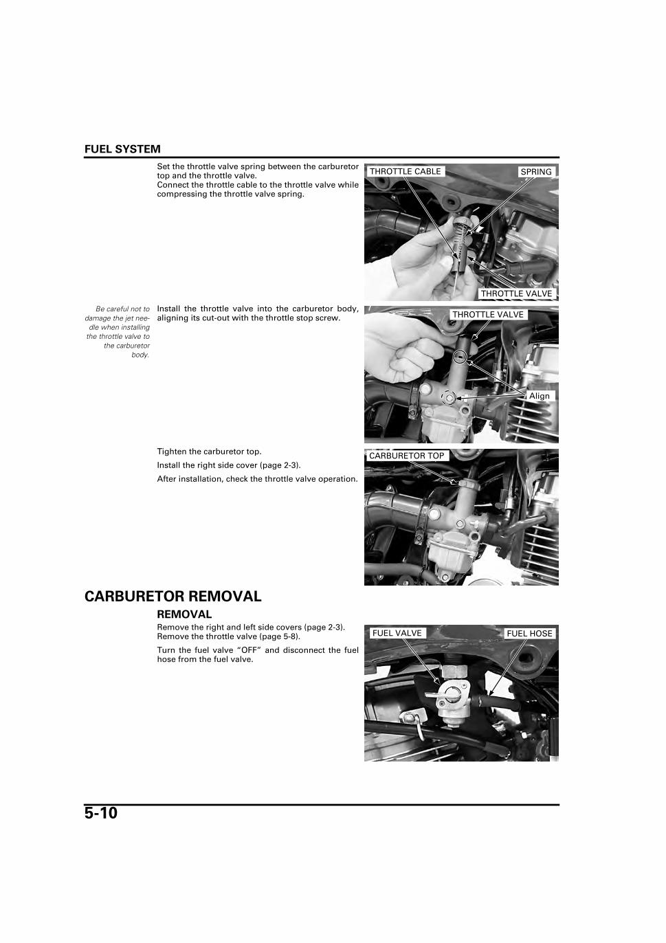
FUEL SYSTEM
5-10
Set the throttle valve spring between the carburetortop and the throttle valve.Connect the throttle cable to the throttle valve whilecompressing the throttle valve spring.
Be careful not todamage the jet nee-
dle when installingthe throttle valve to
the carburetorbody.
Install the throttle valve into the carburetor body,aligning its cut-out with the throttle stop screw.
Tighten the carburetor top.
Install the right side cover (page 2-3).
After installation, check the throttle valve operation.
CARBURETOR REMOVAL
REMOVALRemove the right and left side covers (page 2-3).Remove the throttle valve (page 5-8).
Turn the fuel valve “OFF” and disconnect the fuelhose from the fuel valve.
THROTTLE CABLE SPRING
THROTTLE VALVE
THROTTLE VALVE
Align
CARBURETOR TOP
FUEL VALVE FUEL HOSE

FUEL SYSTEM
5-11
Loosen the drain screw and drain the fuel from thefloat chamber into the approved gasoline container.
Completely drain any residual fuel and tighten thedrain screw to the specified torque.
Release the air vent hose from the clamp.
Disconnect the drain hose from the carburetor.
Loosen the air cleaner connecting hose band screw.Remove the carburetor mounting nuts and carbure-tor.Remove the O-ring from the carburetor.
Disconnect the air vent hose and the fuel hose fromthe carburetor.
CHOKE LEVER
REMOVALRemove the carburetor (page 5-10).
Remove the screw and setting plate.
TORQUE: 1.5 N·m (0.2 kgf·m, 1.1 lbf·ft)
DRAIN HOSE
CLAMP
AIR VENT HOSE
DRAIN SCREW
NUTS
BAND SCREW O-RING
AIR VENT HOSE
FUEL HOSE
SETTING PLATE SCREW

FUEL SYSTEM
5-12
Remove the choke lever.
INSTALLATIONInstall the choke lever to the carburetor.
Install the setting plate, aligning the choke lever ballwith setting plate hole.
Install and tighten the choke lever screw to the spec-ified torque.
Check the choke lever operation.
Install the carburetor (page 5-19).
CHOKE LEVER
CHOKE LEVER
SETTING PLATE
BALL
TORQUE: 2.1 N·m (0.2 kgf·m, 1.5 lbf·ft)
SCREW

FUEL SYSTEM
5-13
AIR CUT-OFF VALVE
REMOVALBe careful when
removing the valvecover. The spring
may pop out.
Remove the carburetor (page 5-10).
Remove the two screws and valve cover.
Remove the spring and check it for deterioration.
Remove the O-ring and diaphragm.
Check the following:
– Diaphragm for pin holes, deterioration or dam-age
– Needle of diaphragm for damage– Air passages for clogging
INSTALLATIONBe sure that the
diaphragm and O-ring do not interfere
with the cover.
Install a new O-ring with the flat side facing the car-buretor body.
Install the following:
– Diaphragm– Spring– Air cut-off valve cover
SCREWS VALVE COVER
SPRING
DIAPHRAGM
O-RING
DIAPHRAGM
O-RING
SPRING
VALVE COVER

FUEL SYSTEM
5-14
Install and tighten the screws to the specifiedtorque.
Install the carburetor (page 5-19).
CARBURETOR DISASSEMBLY
FLOATRemove the three screws and float chamber.
Pull out the float pin.
Remove the float and float valve.
TORQUE: 2.1 N·m (0.2 kgf·m, 1.5 lbf·ft)
SCREWS
SCREWS
FLOAT CHAMBER
FLOAT PIN
FLOAT VALVE
FLOAT

FUEL SYSTEM
5-15
JETSRemove the following:
– Main jet– Slow jet– Needle jet holder– Needle jet– Throttle stop screw/O-ring/spring
Before removing the pilot screw, record the numberof turns until it seats lightly, then remove the pilotscrew, spring, washer and O-ring.
Check each jet for wear or damage.
Check the pilot screw, spring, washer and O-ring.Check the throttle stop screw, spring and O-ring.
Replace the damaged parts, if necessary.
CARBURETOR BODY CLEANINGBlow each air and fuel passage in the carburetorbody with compressed air.
Check each part for wear or damage and replacethem if necessary.
Damage to the pilotscrew seat will
occur if the screwis tightened against
the seat.
NEEDLE JET HOLDER
PILOT SCREW
MAIN JETSLOW JET
NEEDLE JET
THROTTLE STOP SCREW
SPRING/WASHER/O-RING
SPRING/O-RING
MAIN JET
SLOW JET
NEEDLE JET HOLDER
NEEDLE JET
THROTTLE STOP SCREW
O-RING
SPRING
PILOT SCREW
SPRING
WASHER
O-RING
CARBURETOR BODY

FUEL SYSTEM
5-16
CARBURETOR ASSEMBLY
JETSInstall a new O-ring to the throttle stop screw.
Install the spring and throttle stop screw.
Install a new O-ring, washer, spring and pilot screwand return it to its original as noted during removal.
Perform the pilot screw adjustment procedure if anew pilot screw is installed (page 5-21).
1.5 N·m (0.2 kgf·m, 1.1 lbf·ft)
1.8 N·m (0.2 kgf·m, 1.3 lbf·ft)
RETAINER
THROTTLE CABLE
SPRING
THROTTLE VALVEFLOAT PIN
FLOAT
PILOT SCREW
SLOW JET
THROTTLE STOP SCREW
FLOAT VALVE
CARBURETOR BODY
NEEDLE JET HOLDER
NEEDLE JET
O-RING
O-RING
DRAIN SCREW2.1 N·m (0.2 kgf·m, 1.5 lbf·ft)
O-RING
SPRING
WASHER
JET NEEDLE
2.5 N·m (0.3 kgf·m, 1.8 lbf·ft)
FLOAT CHAMBER
2.1 N·m (0.2 kgf·m, 1.5 lbf·ft)
SPRING
SPRING
O-RING
DIAPHRAGM
2.1 N·m (0.2 kgf·m, 1.5 lbf·ft)
2.1 N·m (0.2 kgf·m, 1.5 lbf·ft)
O-RING
MAIN JET
THROTTLE STOP SCREW
O-RING
SPRING
PILOT SCREW
SPRING
WASHER
O-RING

FUEL SYSTEM
5-17
Handle all jets withcare. They can eas-
ily be scored orscratched.
Install the needle jet.
Install and tighten the slow jet, needle jet holder andmain jet to the specified torque.
FLOATCheck the tip of the float valve where it contacts thevalve seat for stepped wear or contamination.Replace the valve if the tip is worn or contaminated.
Check the operation of the float valve.
Inspect the float valve seat for scores, scratches,clogging and damage.If the seat is damaged, replace the carburetor body.
Install the float valve to the float.
Install the float to the carburetor body.
TORQUES:
Slow jet: 1.8 N·m (0.2 kgf·m, 1.3 lbf·ft)
Needle jet holder: 2.5 N·m (0.3 kgf·m, 1.8 lbf·ft)
Main jet: 2.1 N·m (0.2 kgf·m, 1.5 lbf·ft)
MAIN JET
SLOW JET
NEEDLE JET HOLDER
NEEDLE JET
FLOAT VALVE
TIP
VALVE SEAT
FLOAT VALVE
FLOAT

FUEL SYSTEM
5-18
Install the float pin through the body and float.
With the float valve seated and the float arm justtouching the valve, measure the float level with thespecial tool as shown.
The float cannot be adjusted.Replace the float assembly if the float level is out ofspecification.
Install a new O-ring into the float chamber groove.Install the float chamber.
Install and tighten the float chamber screws to thespecified torque.
FLOAT PIN
FLOAT LEVEL: 14.0 mm (0.55 in)
TOOL:
Carburetor float level gauge 07401-0010000
FLOAT LEVEL GAUGE
FLOAT CHAMBER
O-RING
TORQUE: 2.1 N·m (0.2 kgf·m, 1.5 lbf·ft)
SCREWS
FLOAT CHAMBER

FUEL SYSTEM
5-19
CARBURETOR INSTALLATIONConnect the air vent hose and the fuel hose to thecarburetor.
Install a new O-ring onto the carburetor.
Install the carburetor to the insulator and air cleanerconnecting hose.
Tighten the carburetor mounting nuts and aircleaner connecting hose band screw.
Install the throttle valve (page 5-9)Install the right side cover (page 2-3)
Connect the drain hose to the carburetor.
Set the air vent hose to the clamp.
AIR VENT HOSE
FUEL HOSE
O-RING
NUTS
SCREW
DRAIN HOSE
CLAMP
AIR VENT HOSE

FUEL SYSTEM
5-20
After installation,turn the fuel valve
"ON" and make surethere are no fuel
leaks.
Connect the fuel hose to the fuel valve.
INSULATOR
REMOVALRemove the carburetor (page 5-10)
Remove the two bolts, clamp and insulator.Remove the O-ring from the insulator.
INSTALLATIONInstall a new O-ring onto the insulator.Install the insulator and clamp.Install and tighten the bolts.
Install the carburetor (page 5-19)
FUEL VALVE FUEL HOSE
BOLTS
CLAMP
INSULATOR/O-RING
INSULATOR
O-RING
CLAMP
BOLTS

FUEL SYSTEM
5-21
PILOT SCREW ADJUSTMENT • The pilot screw are factory pre-set and no adjust-
ment is necessary unless the pilot screw isreplaced.
• The engine must be warm for accurate adjust-ment. 10 minutes of stop-and-go riding is suffi-cient.
• Use a tachometer with graduations of 50 min-1
(rpm) or smaller that will accurately indicate a 50min-1 (rpm) change.
IDLE DROP PROCEDURE1. Turn the pilot screw clockwise until it is lightly
seated then back it out to the specification given.This is an initial setting prior to the final pilotscrew adjustment.
2. Warm up the engine to operating temperature.
3. Stop the engine and connect a tachometeraccording to the tachometer manufacturer’sinstructions.
4. Disconnect the PAIR control valve vacuum hose,then connect it to the vacuum pump and plug thevacuum port.
5. Apply the specified vacuum to the PAIR controlvalve vacuum hose more than 60 kPa (450 mmHg).
Damage to the pilotscrew seat will
occur if the pilotscrew is
tightened againstthe seat. INITIAL OPENING: UNDECIDED
PILOT SCREW
TOOL:
Vacuum pump Commercially available
VACUUM HOSEPLUG
VACUUM PUMP

FUEL SYSTEM
5-22
6. Start the engine and adjust the idle speed withthe throttle stop screw.
7. Turn the pilot screw inward or outward slowly toobtain the highest engine speed.
8. Lightly open the throttle 2 – 3 times, then adjustthe idle speed with the throttle stop screw.
9. Turn the pilot screw inward gradually until theengine speed drops by UNDECIDED min-1 (rpm).
10.Turn the pilot screw outward to the final open-ing.
11.Remove the plug from the vacuum port, thenremove the vacuum pump and connect the vac-uum hose to the vacuum port.
12.Readjust the idle speed with the throttle stopscrew.
SECONDARY AIR SUPPLY SYSTEM
SYSTEM INSPECTIONRemove the following:
– Right and left side covers (page 2-3).– Right and left horn covers (page 2-7).
Start the engine and warm it up to normal operatingtemperature.
Remove the fuel tank (page 2-4).
Disconnect the air cleaner sub filter-to-PAIR controlvalve hose.Check that the hose joint of the sub filter is cleanand free of carbon deposits.Replace the sub filter if necessary.
If the port is carbon fouled, inspect the PAIR checkvalve.
Install the sub filter in the reverse order of removal.
IDLE SPEED: 1,300 ± 100 min-1 (rpm)
IDLE SPEED: 1,300 ± 100 min-1 (rpm)
FINAL OPENING: UNDECIDED
IDLE SPEED: 1,400 ± 100 min-1 (rpm)
THROTTLE STOP SCREW
The sub filter has adirection mark.
SUB FILTER-to-PAIR CONTROL VALVE HOSE
FILTER

FUEL SYSTEM
5-23
Disconnect the PAIR control valve vacuum hosefrom the joint of the insulator and plug it to keep airfrom entering.Connect the vacuum pump to the PAIR control valvevacuum hose.
Start the engine and open the throttle slightly to becertain that air is sucked in through the PAIR aircleaner sub filter-to-open air hose.If the air is not sucked in, check the PAIR air cleanersub filter-to-PAIR control valve hose, PAIR aircleaner sub filter and PAIR air cleaner sub filter-to-open air hose for clogging.
With the engine running, gradually apply vacuum toPAIR control valve.Check that the air intake port stops drawing air, andthat the vacuum does not bleed.
If the air is drawn in, or if the specified vacuum isnot maintained, replace the PAIR control valve.
PAIR CHECK VALVE INSPECTIONRemove the left horn cover (page 2-7).
Remove the two screws and valve cover.Remove the PAIR check valve.
Check the valve reed for fatigue or damage.Replace the PAIR control valve if the seat rubber iscracked, deteriorated or damaged, or if there isclearance between the reed and seat.
TOOL:
Vacuum pump Commercially available
SPECIFIED VACUUM: 60 kPa (450 mm Hg)
VACUUM HOSEPLUG
AIR CLEANER SUB FILTER-to-PAIR CONTROL VALVE HOSE
AIR CLEANER SUB FILTER-to-OPEN AIR HOSE
SCREWS
COVERPAIR CHECK VALVE
REED
SEAT RUBBER

FUEL SYSTEM
5-24
Install the PAIR check valve.
Install the PAIR check valve cover and tighten thescrews.
Install the left horn cover (page 2-7).
PAIR CONTROL VALVE REMOVAL/INSTALLATIONRemove the following:
– Right and left horn covers (page 2-7)– Fuel tank (page 2-4)
Unhook the PAIR control valve vacuum hose fromthe clamp, remove the horn cover stay mountingbolt and the horn cover stays.
Disconnect the PAIR control valve vacuum hose.
PAIR CHECK VALVE
SCREWS
COVER
BOLT
HORN COVER STAY VACUUM HOSE
CLAMP
VACUUM HOSE

FUEL SYSTEM
5-25
Disconnect the air cleaner sub filter-to-PAIR controlvalve hose.
Release the PAIR control valve side clamp.
Remove the PAIR control valve mounting nuts.
Disconnect the air supply pipe-to-PAIR control valvehose from the PAIR control valve.
Remove the PAIR control valve.
Connect the air supply pipe-to-PAIR control valvehose to the PAIR control valve.
Set the PAIR control valve and tighten the PAIR con-trol valve mounting nuts to the specified torque.
Set the PAIR control valve side clamp in position.
Connect the air cleaner sub filter-to-PAIR controlvalve hose.
Connect the PAIR control valve vacuum hose.
Set the horn cover stays by inserting the tabs of thehorn cover stays into the hole of the frame.Install and tighten the horn cover stay mountingbolt.
Set the PAIR control valve vacuum hose to theclamp.
Install the following:– Fuel tank (page 2-4)– Right and left horn covers (page 2-7)
CLAMP
NUTS
CONTROL VALVE
SUB FILTER-to-PAIR CONTROL VALVE HOSE
AIR SUPPLY PIPE-to-PAIR CONTROL VALVE HOSE
TORQUE: PAIR control valve mounting nut:
9 N·m (0.9 kgf·m, 6.6 lbf·ft) CLAMP
NUTS
CONTROL VALVE
SUB FILTER-to-PAIR CONTROL VALVE HOSE
AIR SUPPLY PIPE-to-PAIR CONTROL VALVE HOSE
VACUUM HOSE
BOLT
HORN COVER STAY VACUUM HOSE
CLAMPInsert

FUEL SYSTEM
5-26
FUEL STRAINER
REMOVALDrain the fuel from the fuel tank.
Remove the fuel tank (page 2-4).
Loosen the fuel valve lock nut.
Remove the fuel strainer and fuel valve assemblyfrom the fuel tank.
Remove the fuel strainer and O-ring from the fuelvalve.
CLEANINGClean the fuel strainer with compressed air.
INSTALLATIONInstall a new O-ring onto the fuel strainer, andinstall the fuel strainer into the fuel valve.
Install the fuel strainer and fuel valve assembly intothe fuel tank.
Tighten the fuel valve lock nut.
Install the fuel tank (page 2-4).
LOCK NUT
FUEL VALVE
FUEL STRAINER
O-RING
FUEL
FUEL VALVE
FUEL STRAINER
LOCK NUT

6-1
6
6. ENGINE REMOVAL/INSTALLATION
SYSTEM COMPONENTS ······························ 6-2
SERVICE INFORMATION ······························ 6-3
DRIVE SPROCKET ········································· 6-4
ENGINE REMOVAL ········································6-6
ENGINE INSTALLATION ······························6-10

ENGINE REMOVAL/INSTALLATION
6-2
ENGINE REMOVAL/INSTALLATION
SYSTEM COMPONENTS
45 N·m (4.6 kgf·m, 33 lbf·ft)
54 N·m (5.5 kgf·m, 40 lbf·ft)
59 N·m (6.0 kgf·m, 44 lbf·ft)
12 N·m (1.2 kgf·m, 9 lbf·ft)
27 N·m (2.8 kgf·m, 20 lbf·ft)
45 N·m (4.6 kgf·m, 33 lbf·ft)
27 N·m (2.8 kgf·m, 20 lbf·ft)

ENGINE REMOVAL/INSTALLATION
6-3
SERVICE INFORMATIONGENERAL • Place the motorcycle on level ground before starting any work. • When removing/installing the engine, tape the frame around the engine beforehand for frame protection. • Support the engine using a floor jack or other adjustable support to ease engine hangar bolt stresses. • The following components require engine removal for service.
– Cylinder head/valves (page 7-12)– Cylinder/piston (page 8-4/8-10)– Crankshaft (page 11-7)– Transmission (page 11-8)– Kickstarter (page 11-14)
SPECIFICATIONS
TORQUE VALUES
ITEM SPECIFICATIONS
Engine oil capacity After draining 0.8 liter (0.8 US qt, 0.7 lmp qt)After disassembly 1.1 liter (1.2 US qt, 1.0 lmp qt)
Engine dry weight 30.5 kg (67.2 lbs)
Upper engine hanger plate mounting nut 27 N·m (2.8 kgf·m, 20 lbf·ft)Front engine hanger bracket mounting nut 27 N·m (2.8 kgf·m, 20 lbf·ft) Swingarm pivot nut 59 N·m (6.0 kgf·m, 44 lbf·ft) Rear upper/lower engine mounting nut 54 N·m (5.5 kgf·m, 40 lbf·ft)Pillion step bracket bolt 45 N·m (4.6 kgf·m, 33 lbf·ft)Gearshift pedal pinch bolt 12 N·m (1.2 kgf·m, 9 lbf·ft)

ENGINE REMOVAL/INSTALLATION
6-4
DRIVE SPROCKETREMOVALRaise the rear wheel off the ground by placing awork stand or box under the frame.
Disconnect the brake rod by removing the adjustingnut, and remove the spring and joint pin.
Loosen the drive chain by loosening the rear axlenut, lock nut and the drive chain adjusting bolt.
Remove the gearshift pedal pinch bolt and the gear-shift pedal.
Remove the two bolts, washers, left crankcase rearcover, grommet, collar and the drive chain guide.
Remove the two fixing plate mounting bolts.Turn the fixing plate until the slots of the fixing plateand the spline of the countershaft are aligned.Remove the fixing plate, drive chain and the drivesprocket.
BRAKE RODADJUSTING NUT
JOINT PIN SPRING
DRIVE CHAIN LOCK NUT
AXLE NUT ADJUSTING BOLT
GEARSHIFT PEDAL
PINCH BOLTBOLTS/WASHERS
COVER/GROMMET/CHAIN GUIDE
COLLAR
FIXING PLATE
DRIVE CHAINBOLTS
DRIVE SPROCKET
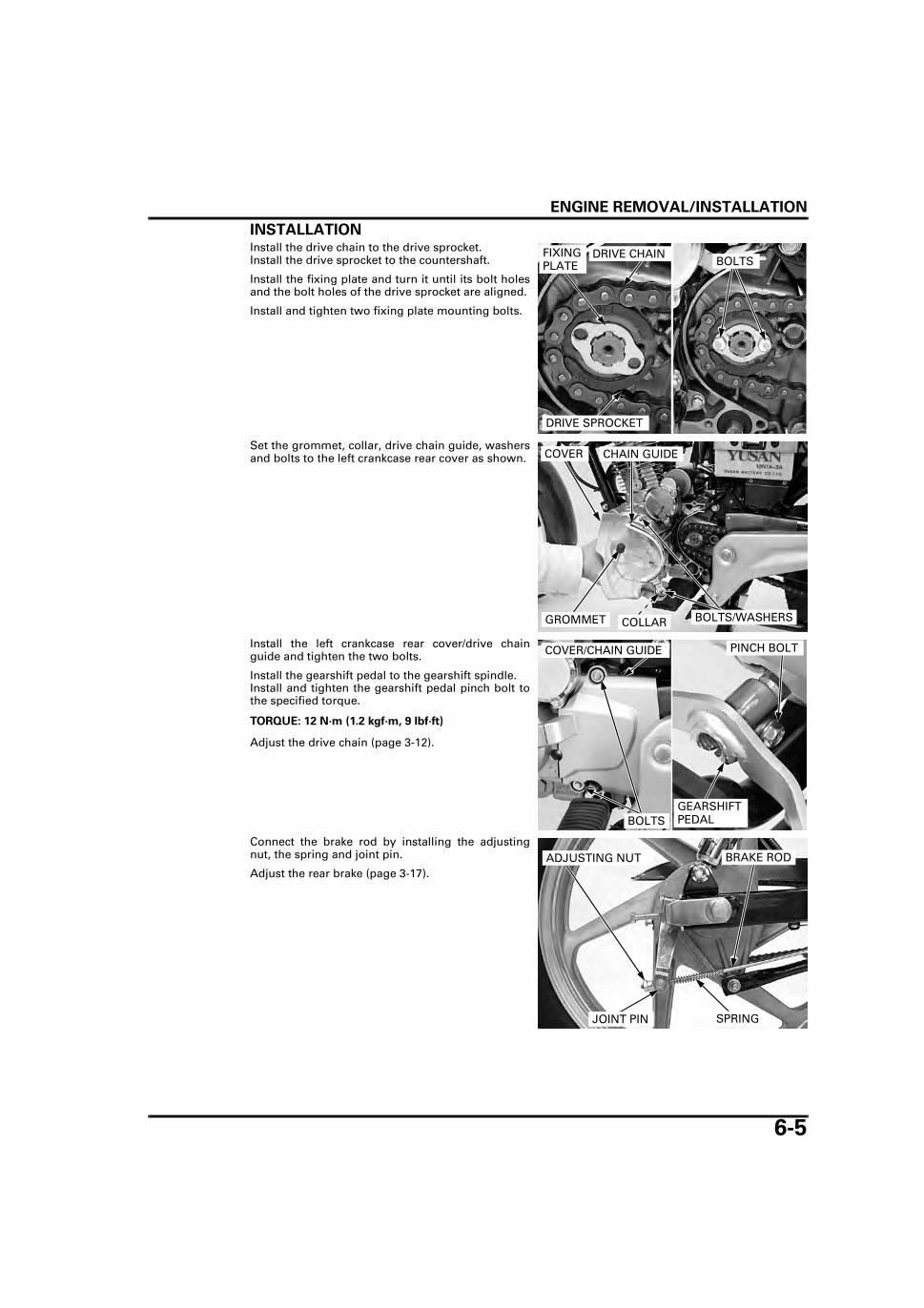
ENGINE REMOVAL/INSTALLATION
6-5
INSTALLATIONInstall the drive chain to the drive sprocket.Install the drive sprocket to the countershaft.
Install the fixing plate and turn it until its bolt holesand the bolt holes of the drive sprocket are aligned.
Install and tighten two fixing plate mounting bolts.
Set the grommet, collar, drive chain guide, washersand bolts to the left crankcase rear cover as shown.
Install the left crankcase rear cover/drive chainguide and tighten the two bolts.
Install the gearshift pedal to the gearshift spindle.Install and tighten the gearshift pedal pinch bolt tothe specified torque.
Adjust the drive chain (page 3-12).
Connect the brake rod by installing the adjustingnut, the spring and joint pin.
Adjust the rear brake (page 3-17).
FIXING PLATE
DRIVE CHAIN
DRIVE SPROCKET
BOLTS
BOLTS/WASHERSGROMMET
COVER CHAIN GUIDE
COLLAR
TORQUE: 12 N·m (1.2 kgf·m, 9 lbf·ft)
BOLTS
COVER/CHAIN GUIDE
GEARSHIFT PEDAL
PINCH BOLT
BRAKE RODADJUSTING NUT
JOINT PIN SPRING

ENGINE REMOVAL/INSTALLATION
6-6
ENGINE REMOVALDrain the engine oil (page 3-10).
Remove the following:
– Fuel tank (page 2-4)– Right and left horn covers (page 2-7)– Muffler (page 2-8)– Carburetor (page 5-10)– Drive sprocket (page 6-4)
Disconnect the following:
– Gear position switch 6P connector– Yellow and Pink alternator wire connectors– Black/Red exciter coil wire connector– Green/White and Blue/Yellow ignition pulse gen-
erator wire connectors
Unhook the PAIR control valve vacuum hose fromthe clamp, remove the horn cover stay bolt, rightand left horn cover stays.
Disconnect the PAIR control valve vacuum hosefrom the PAIR control valve.
Loosen the clutch cable lock nut and clutch cableadjusting nut.
Release the clutch cable from the stay and discon-nect the clutch cable end from the lifter arm.
Pull back the rubber cap, remove the terminal nutand disconnect the starter motor wire from thestarter motor terminal.
Remove the starter motor rear mounting bolt anddisconnect the ground cable from the starter motor.
Disconnect the crankcase breather hose from thecrankcase.
GEAR POSITION SWITCH 6P CONNECTOR
ALTERNATOR WIRE CONNECTORS
IGNITION PULSE GENERATOR WIRE CONNECTORS
EXCITER COIL WIRE CONNECTOR
VACUUM HOSE
BOLT
HORN COVER STAY
CLAMP
LOCK NUT
ADJUSTING NUT
STAYLIFTER ARM
CLUTCH CABLE
TERMINAL NUT
BOLT
STARTER MOTOR WIRE
GROUND CABLEBREATHER HOSE
RUBBER CAP

ENGINE REMOVAL/INSTALLATION
6-7
Disconnect the spark plug cap from the spark plugand release the spark plug wire from the clamp.
Remove two air supply pipe mounting bolts.Disconnect the air supply pipe and O-ring from thecylinder head cover.
Remove the heat protector mounting bolt and theheat protector.
Remove the right pillion step bracket bolt.
Remove the swingarm pivot nut, right pillion stepbracket and the washer.
SPARK PLUG CAPCLAMP
SPARK PLUG WIRE
AIR SUPPLY PIPE/O-RING BOLTS
BOLT
HEAT PROTECTOR
Do not remove theswingarm pivot.
SWINGARM PIVOT NUT
BOLT
PILLION STEP BRACKET
WASHER

ENGINE REMOVAL/INSTALLATION
6-8
Unhook and remove the rear brake pedal returnspring.
Unhook and the rear brake light switch spring fromthe rear brake pedal.
Remove the left pillion step bracket bolt.
Rotate the left pillion step bracket so that the enginerear upper/lower mounting bolts are accessible.
Remove the wire band.
SPRING
SPRING
BRAKE PEDAL
Do not remove theswingarm pivot
bolt.BOLT
Rotate
WIRE BAND
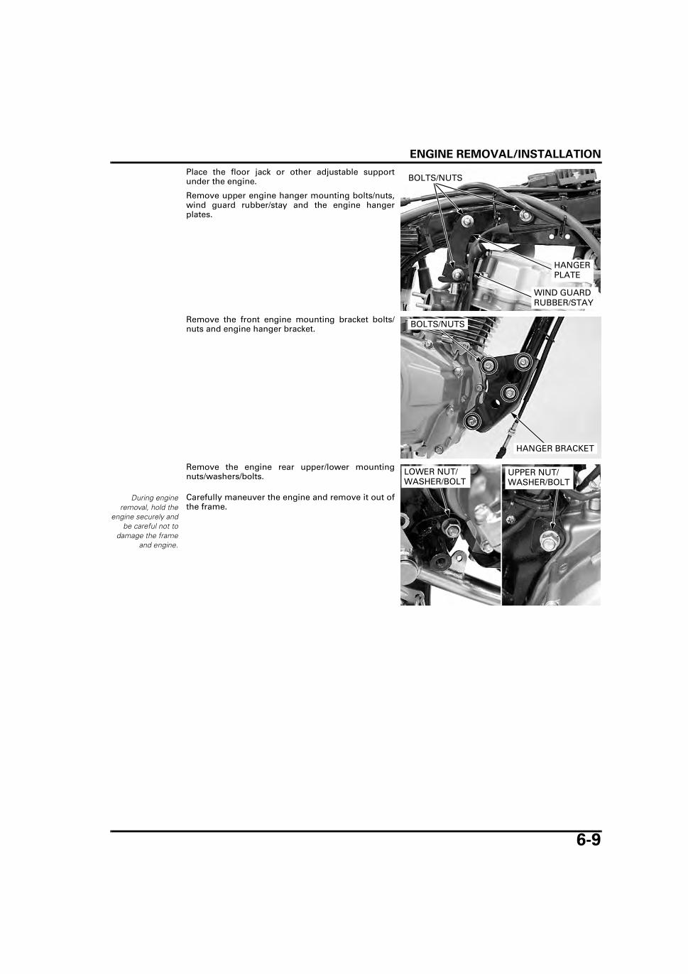
ENGINE REMOVAL/INSTALLATION
6-9
Place the floor jack or other adjustable supportunder the engine.
Remove upper engine hanger mounting bolts/nuts,wind guard rubber/stay and the engine hangerplates.
Remove the front engine mounting bracket bolts/nuts and engine hanger bracket.
Remove the engine rear upper/lower mountingnuts/washers/bolts.
Carefully maneuver the engine and remove it out ofthe frame.
WIND GUARD RUBBER/STAY
BOLTS/NUTS
HANGER PLATE
HANGER BRACKET
BOLTS/NUTS
During engineremoval, hold the
engine securely andbe careful not to
damage the frameand engine.
LOWER NUT/WASHER/BOLT
UPPER NUT/WASHER/BOLT
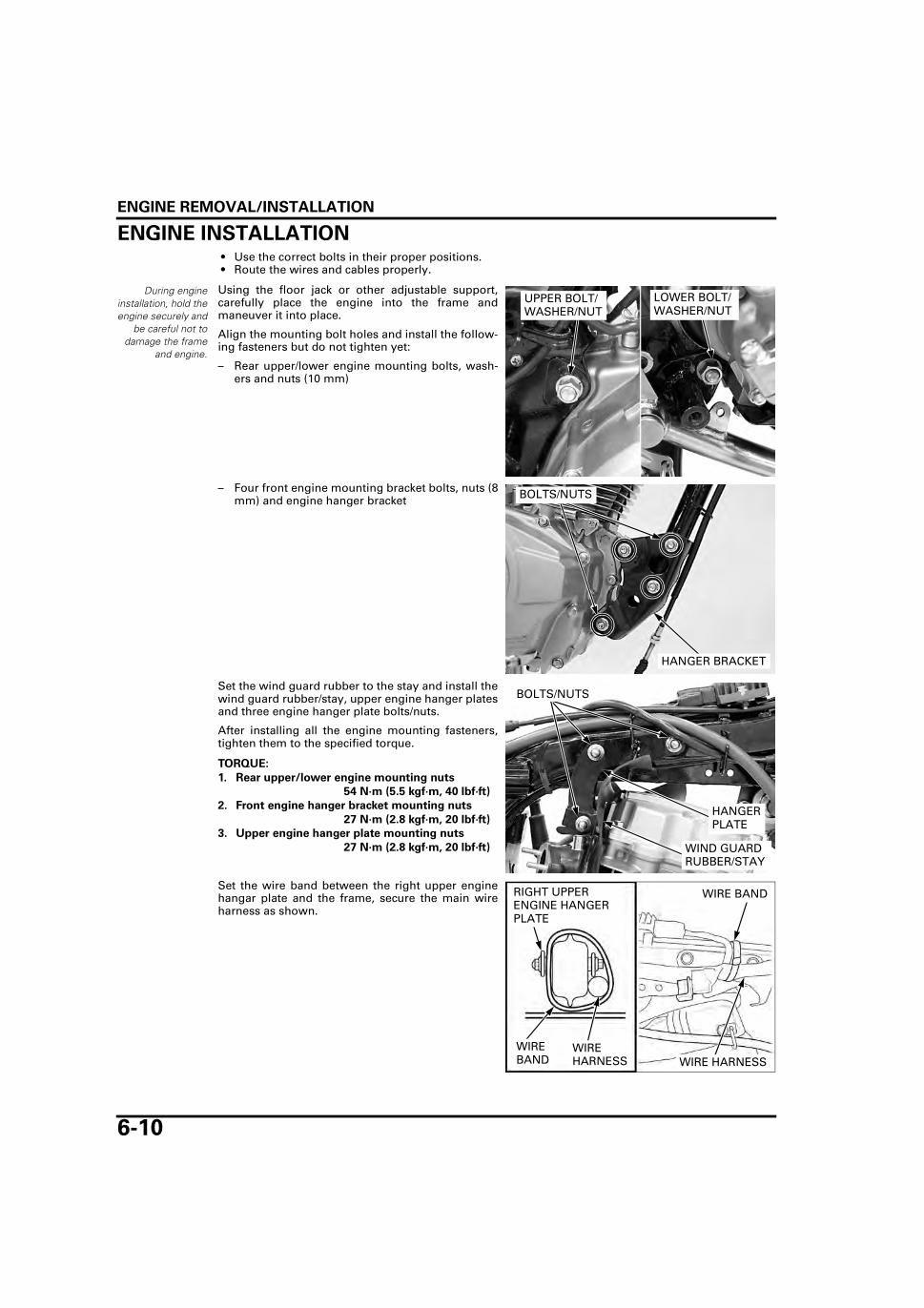
ENGINE REMOVAL/INSTALLATION
6-10
ENGINE INSTALLATION • Use the correct bolts in their proper positions. • Route the wires and cables properly.
Using the floor jack or other adjustable support,carefully place the engine into the frame andmaneuver it into place.
Align the mounting bolt holes and install the follow-ing fasteners but do not tighten yet:
– Rear upper/lower engine mounting bolts, wash-ers and nuts (10 mm)
– Four front engine mounting bracket bolts, nuts (8mm) and engine hanger bracket
Set the wind guard rubber to the stay and install thewind guard rubber/stay, upper engine hanger platesand three engine hanger plate bolts/nuts.
After installing all the engine mounting fasteners,tighten them to the specified torque.
Set the wire band between the right upper enginehangar plate and the frame, secure the main wireharness as shown.
During engineinstallation, hold theengine securely and
be careful not todamage the frame
and engine.
LOWER BOLT/WASHER/NUT
UPPER BOLT/WASHER/NUT
HANGER BRACKET
BOLTS/NUTS
TORQUE:
1. Rear upper/lower engine mounting nuts
54 N·m (5.5 kgf·m, 40 lbf·ft)
2. Front engine hanger bracket mounting nuts
27 N·m (2.8 kgf·m, 20 lbf·ft)
3. Upper engine hanger plate mounting nuts
27 N·m (2.8 kgf·m, 20 lbf·ft) WIND GUARD RUBBER/STAY
BOLTS/NUTS
HANGER PLATE
WIRE HARNESS
WIRE BAND
WIRE BAND
RIGHT UPPER ENGINE HANGER PLATE
WIRE HARNESS

ENGINE REMOVAL/INSTALLATION
6-11
Set the left pillion step bracket in its original posi-tion and install the left pillion step bracket bolt.
Hook the rear brake light switch spring to the rearbrake pedal.
Install the rear brake pedal return spring.
Set the washer to the swingarm pivot and install theright pillion step bracket and the right pillion stepbracket bolt.Install the swingarm pivot nut and tighten it to thespecified torque.
Tighten the right and left pillion step bracket bolts tothe specified torque.
BOLT
PILLION STEP BRACKET
SPRING
BRAKE PEDAL
SPRING
TORQUE: 59 N·m (6.0 kgf·m, 44 lbf·ft)
TORQUE: 45 N·m (4.6 kgf·m, 33 lbf·ft)
SWINGARM PIVOT NUT
BOLT
PILLION STEP BRACKET
WASHER

ENGINE REMOVAL/INSTALLATION
6-12
Install the heat protector and the heat protectormounting bolt and tighten it.
Coat new O-ring with engine oil and install it to theair supply pipe.
Install the air supply pipe/O-ring to the cylinderhead and tighten two bolts.
Set the spark plug wire to the clamp.Connect the spark plug cap to the spark plug.
BOLT
HEAT PROTECTOR
O-RING
AIR SUPPLY PIPE/O-RING BOLTS
SPARK PLUG CAPCLAMP
SPARK PLUG WIRE
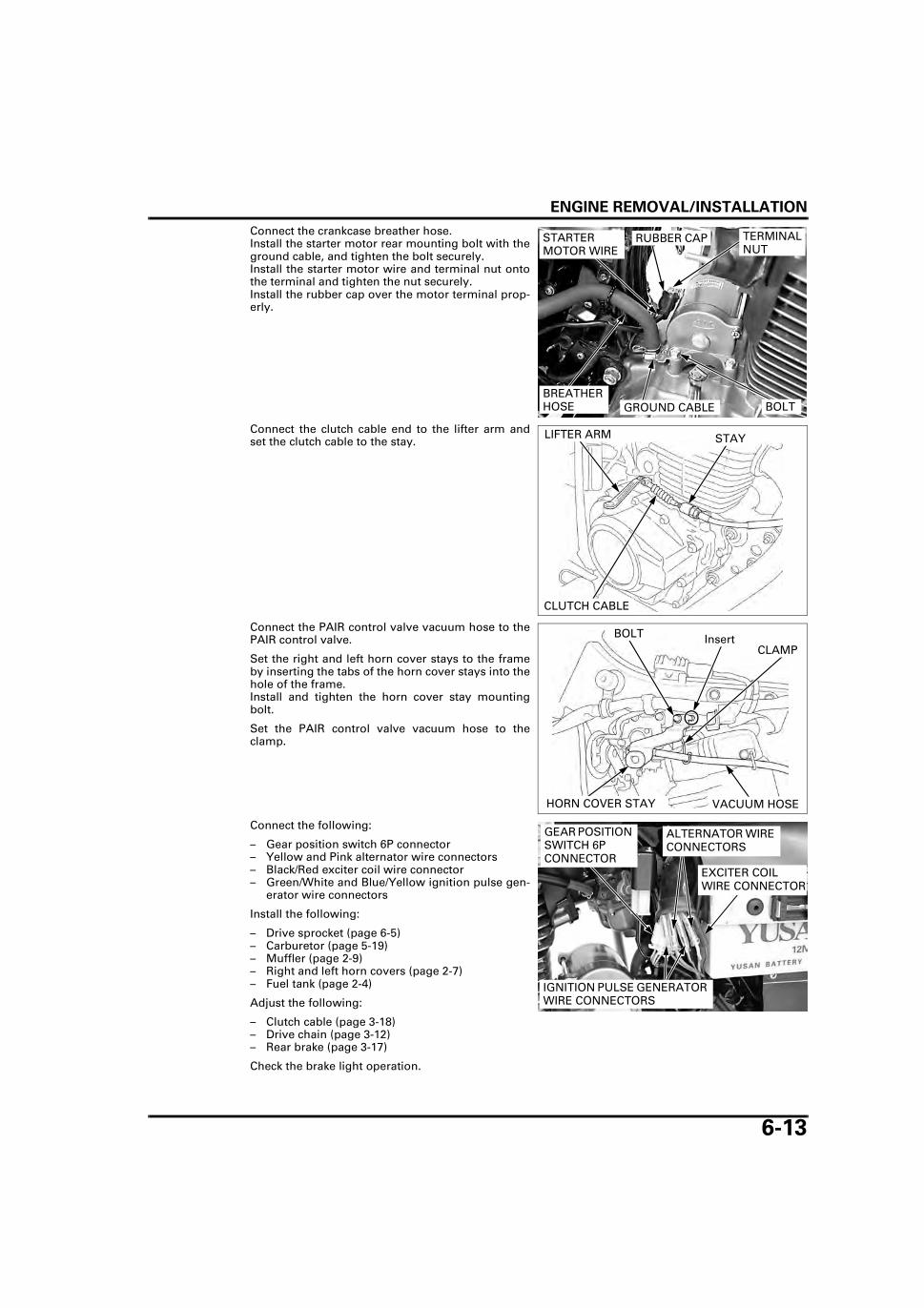
ENGINE REMOVAL/INSTALLATION
6-13
Connect the crankcase breather hose.Install the starter motor rear mounting bolt with theground cable, and tighten the bolt securely.Install the starter motor wire and terminal nut ontothe terminal and tighten the nut securely.Install the rubber cap over the motor terminal prop-erly.
Connect the clutch cable end to the lifter arm andset the clutch cable to the stay.
Connect the PAIR control valve vacuum hose to thePAIR control valve.
Set the right and left horn cover stays to the frameby inserting the tabs of the horn cover stays into thehole of the frame.Install and tighten the horn cover stay mountingbolt.
Set the PAIR control valve vacuum hose to theclamp.
Connect the following:
– Gear position switch 6P connector– Yellow and Pink alternator wire connectors– Black/Red exciter coil wire connector– Green/White and Blue/Yellow ignition pulse gen-
erator wire connectors
Install the following:
– Drive sprocket (page 6-5)– Carburetor (page 5-19)– Muffler (page 2-9)– Right and left horn covers (page 2-7)– Fuel tank (page 2-4)
Adjust the following:
– Clutch cable (page 3-18)– Drive chain (page 3-12)– Rear brake (page 3-17)
Check the brake light operation.
TERMINAL NUT
BOLT
STARTER MOTOR WIRE
GROUND CABLEBREATHER HOSE
RUBBER CAP
STAYLIFTER ARM
CLUTCH CABLE
VACUUM HOSE
BOLT
HORN COVER STAY
CLAMPInsert
GEAR POSITION SWITCH 6P CONNECTOR
ALTERNATOR WIRE CONNECTORS
IGNITION PULSE GENERATOR WIRE CONNECTORS
EXCITER COIL WIRE CONNECTOR

MEMO
7-1
7
7. CYLINDER HEAD/VALVES
SYSTEM COMPONENTS ······························ 7-2
SERVICE INFORMATION ······························ 7-3
TROUBLESHOOTING ···································· 7-5
CYLINDER COMPRESSION··························· 7-6
CYLINDER HEAD COVER·······························7-7
ROCKER ARM HOLDER ·······························7-10
CYLINDER HEAD ··········································7-12

CYLINDER HEAD/VALVES
7-2
CYLINDER HEAD/VALVES
SYSTEM COMPONENTS
32 N·m (3.3 kgf·m, 24 lbf·ft)20 N·m (2.0 kgf·m, 15 lbf·ft)
10 N·m (1.0 kgf·m, 7 lbf·ft)

CYLINDER HEAD/VALVES
7-3
SERVICE INFORMATION
GENERAL • This section covers service of the cylinder head, valves and, rocker arms. • The rocker arm services can be done with the engine installed on the frame. To service the cylinder head parts, the
engine must be removed from the frame. • Be careful not to damage the mating surfaces when removing the cylinder head cover and cylinder head. • When disassembling, mark and store the disassembled parts to ensure that they are reinstalled in their original loca-
tions. • Clean all disassembled parts with cleaning solvent and dry them by blowing them off with compressed air before
inspection. • Rocker arm lubricating oil is fed through oil passage in the cylinder head. Clean the oil passage before assembling cyl-
inder head.
SPECIFICATIONSUnit: mm (in)
TORQUE VALUES
ITEM STANDARD SERVICE LIMIT
Cylinder compression 1,226 kPa (12.5 kgf/cm2, 178 psi)at 450 min-1 (rpm)
–
Valve clearance IN/EX 0.08 ± 0.02 (0.003 ± 0.001) –Valve,valve guide
Valve stem O.D. IN 5.450 – 5.465 (0.2146 – 0.2152) 5.42 (0.213)EX 5.430 – 5.445 (0.2138 – 0.2144) 5.40 (0.213)
Valve guide I.D. IN/EX 5.475 – 5.485 (0.2156 – 0.2159) 5.50 (0.217)Stem-to-guide clear-ance
IN 0.010 – 0.035 (0.0004 – 0.0014) 0.12 (0.005)EX 0.030 – 0.055 (0.0012 – 0.0022) 0.14 (0.006)
Valve seat width IN/EX 1.2 – 1.5 (0.05 – 0.06) 2.0 (0.08)Valve spring free length
Inner IN/EX 33.5 (1.32) 30.0 (1.18)Outer IN/EX 40.9 (1.61) 39.8 (1.57)
Push rod length 141.15 – 141.45 (5.557 – 5.569) 141.0 (5.55)Rocker arm Arm I.D. IN/EX 12.000 – 12.018 (0.4724 – 0.4731) 12.05 (0.474)
Shaft O.D. IN/EX 11.977 – 11.995 (0.4715 – 0.4722) 11.95 (0.470)Arm holder I.D IN/EX 12.000 – 12.027 (0.4724 – 0.4735) 12.05 (0.474)Arm-to-shaft clear-ance
IN/EX 0.005 – 0.041 (0.0002 – 0.0016) 0.10 (0.004)
Cylinder head warpage – 0.05 (0.002)
Cylinder head nut 32 N·m (3.3 kgf·m, 24 lbf·ft) Apply oil to the threads and seating surface.Cylinder head bolt 20 N·m (2.0 kgf·m, 15 lbf·ft)Cylinder bolt 10 N·m (1.0 kgf·m, 7 lbf·ft)Rocker arm shaft bolt 12 N·m (1.2 kgf·m, 9 lbf·ft)Timing hole cap 6 N·m (0.6 kgf·m, 4.4 lbf·ft)Crankshaft hole cap 8 N·m (0.8 kgf·m, 5.9 lbf·ft)

CYLINDER HEAD/VALVES
7-4
TOOLS
Valve spring compressor07757-0010000
Valve guide driver, 5.35 mm07742-0010100
Valve seat cutter, 24.5 mm (45° EX)07780-0010100
Valve seat cutter, 33 mm (45° IN)07780-0010800
Flat cutter, 25 mm (32° EX)07780-0012000
Flat cutter, 33 mm (32° IN)07780-0012900
Interior cutter, 30 mm (60° IN/EX)07780-0014000
Cutter holder, 5.5 mm07781-0010101
Valve guide reamer, 5.485 mm07984-0980001

CYLINDER HEAD/VALVES
7-5
TROUBLESHOOTING • Engine top-end problems usually affect engine performance. These can be diagnosed by a compression or leak down
test, or by tracing engine noises to the top-end with a sounding rod stethoscope. • If the performance is poor at low speeds, check the crankcase breather tube for white smoke. If the tube is smoky, check
a seized piston ring (page 8-10).
Compression too low, hard starting or poor performance at low speed • Valves
– Incorrect valve adjustment– Burned or bent valves– Incorrect valve timing– Broken valve spring– Uneven valve seating– Valve stuck open
• Cylinder head– Leaking or damaged cylinder head gasket– Warped or cracked cylinder head– Loose spark plug
• Worn cylinder (page 8-4) • Worn piston or piston rings (page 8-10)
Compression too high, overheating or knocking • Excessive carbon build-up in cylinder head or on top of piston • Faulty ignition timing.
Excessive smoke • Worn valve stem or valve guide • Damaged stem seal • Faulty cylinder (page 8-4) • Faulty piston or piston rings (page 8-10)
Excessive noise • Cylinder head
– Incorrect valve adjustment– Sticking valve or broken valve spring– Worn or damaged push rod– Worn rocker arm and/or shaft
• Faulty cylinder (page 8-4) • Faulty piston or piston rings (page 8-10)
Rough idle • Low cylinder compression • Intake air leak

CYLINDER HEAD/VALVES
7-6
CYLINDER COMPRESSIONWarm up the engine to normal operating tempera-ture.
Stop the engine.
Disconnect the spark plug cap and remove the sparkplug.
Install the compression gauge into the spark plughole.Shift the transmission in neutral.Push the choke lever down fully (open).
Open the throttle all the way and crank the enginewith the kickstarter or starter motor until the gaugereading stops rising.The maximum reading is usually reached within 4 –7 seconds.
If compression is high, it indicates that carbondeposits have accumulated on the combustionchamber and/or the piston crown.
If compression is low, pour 3 – 5 cc (0.1 – 0.2 oz) ofclean engine oil into the cylinder through the sparkplug hole and recheck the compression.
If the compression increases from the previousvalue, check the cylinder, piston and piston rings. • Leaking cylinder head gasket • Worn piston ring • Worn cylinder and piston
If compression is the same as the previous value,check the valves for leakage.
SPARK PLUG
SPARK PLUG CAP
To avoid dischargingthe battery, do notoperate the starter
motor for morethan seven sec-
onds.
COMPRESSION PRESSURE:
1,226 kPa (12.5 kgf/cm2, 178 psi) at 450 min-1(rpm)
COMPRESSION GAUGE

CYLINDER HEAD/VALVES
7-7
CYLINDER HEAD COVERREMOVALRemove the horn cover stays (page 6-6).
Remove the two air supply pipe mounting bolts anddisconnect the air supply pipe from the cylinderhead cover.
Remove the three cylinder head cover bolts.
Remove the timing hole cap and crankshaft holecap.
Rotate the crankshaft counterclockwise and alignthe index line of the "T" mark on the flywheel withthe index notch on the left crankcase cover.Make sure that the piston is at TDC (Top Dead Cen-ter) on the compression stroke. (The rocker armsshould be loose.)If the rocker arms are tight, rotate the crankshaftcounterclockwise 360°(1 full turn) and realign theindex line of the "T" mark with the index notchagain.
BOLTS
AIR SUPPLY PIPE
BOLTSCYLINDER HEAD COVER
TIMING HOLE CAP
CRANKSHAFT HOLE CAP
INDEX LINE
"T" MARKINDEX NOTCH

CYLINDER HEAD/VALVES
7-8
Rotate the crankshaft until the intake rocker arm isat the lowest position.Remove the cylinder head cover from the right sideof the frame.
Remove the O-ring and joint pin.
Remove the cylinder head cover packing.
INSTALLATIONCoat new O-ring with engine oil.Install a new O-ring to the joint pin and install thejoint pin to the cylinder head.
Install a new packing into the cylinder head covergroove.
Rotate the crankshaft until the intake rocker arm isat the lowest position (page 7-8).
Install the cylinder head cover from the right side ofthe frame.
Install and tighten the bolts to the cylinder headcover.
INTAKE ROCKER ARM
PACKING
CYLINDER HEAD COVER
O-RING JOINT PIN
PACKING
CYLINDER HEAD COVER
O-RING JOINT PIN
BOLTSCYLINDER HEAD COVER
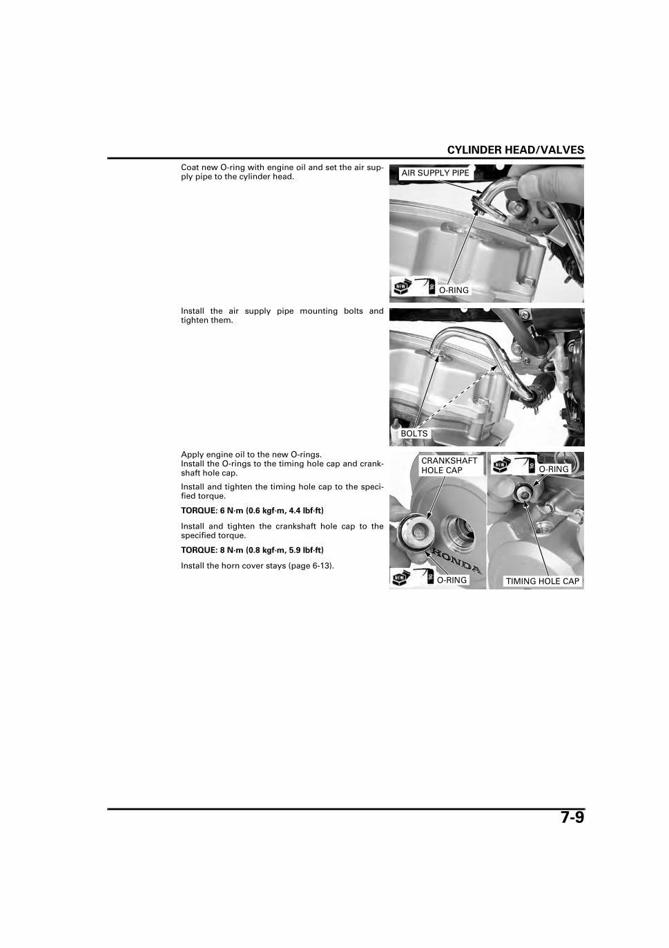
CYLINDER HEAD/VALVES
7-9
Coat new O-ring with engine oil and set the air sup-ply pipe to the cylinder head.
Install the air supply pipe mounting bolts andtighten them.
Apply engine oil to the new O-rings.Install the O-rings to the timing hole cap and crank-shaft hole cap.
Install and tighten the timing hole cap to the speci-fied torque.
Install and tighten the crankshaft hole cap to thespecified torque.
Install the horn cover stays (page 6-13).
AIR SUPPLY PIPE
O-RING
BOLTS
TORQUE: 6 N·m (0.6 kgf·m, 4.4 lbf·ft)
TORQUE: 8 N·m (0.8 kgf·m, 5.9 lbf·ft)
TIMING HOLE CAP
CRANKSHAFT HOLE CAP
O-RING
O-RING

CYLINDER HEAD/VALVES
7-10
ROCKER ARM HOLDERREMOVALRemove the cylinder head cover (page 7-7).
Remove the rocker arm holder bolts and rocker armholder assembly.
Do not drop thedowel pins into thecrankcase from the
cylinder head.
Remove the dowel pins.
DISASSEMBLY/INSPECTIONRemove the rocker arm shaft bolts and rocker armshafts.Remove the rocker arms.
Inspect the rocker arms and shafts for wear or dam-age.
Measure the O.D. of each rocker arm shaft.
Measure the I.D. of each rocker arm.
Subtract each rocker arm shaft O.D. from the corre-sponding rocker arm I.D. to obtain the rocker arm-to-arm shaft clearance.
BOLTS
ROCKER ARM HOLDER ASSEMBLY
DOWEL PINS
SHAFTS
BOLTS ROCKER ARMS
SERVICE LIMIT: 11.95 mm (0.470 in)
SERVICE LIMIT: 12.05 mm (0.474 in)
SERVICE LIMIT: 0.10 mm (0.004 in)
ROCKER ARMSHAFT

CYLINDER HEAD/VALVES
7-11
Measure the I.D. of each rocker arm holder.
ASSEMBLYApply clean engine oil to the rocker arms and shaftssliding surfaces.
Set and hold the rocker arm on the holder, theninstall the shaft.Turn the shaft with a screwdriver to align the holderhole with the shaft hole.
Install and tighten the rocker arm shaft bolts to thespecified torque.
INSTALLATIONThe push rods are
interchangeable.Apply clean engine oil to the ends of the push rods.Install the dowel pins.
SERVICE LIMIT: 12.05 mm (0.474 in)
ROCKER ARM HOLDER
SHAFT
ROCKER ARMAlign (HOLDER HOLE/SHAFT HOLE)
ROCKER ARM HOLDER
TORQUE: 12 N·m (1.2 kgf·m, 9 lbf·ft)
BOLTS
DOWEL PINS
PUSH RODS

CYLINDER HEAD/VALVES
7-12
Install the rocker arm holder assembly.Install the rocker arm holder bolts and tighten them.
Check and adjust the valve clearance (page 3-8).
CYLINDER HEAD
REMOVALRemove the following:
– Engine (page 6-6)– Cylinder head cover (page 7-7)– Rocker arm holder (page 7-10)
Remove the push rods.
Loosen the cylinder bolts.
Remove the left side cylinder head bolt and sealingwasher.
Remove the cylinder head nuts, washers and cylin-der head.
BOLTS
ROCKER ARM HOLDER ASSEMBLY
PUSH RODS
BOLTS
CYLINDER HEAD BOLT/SEALING WASHER
NUTS/ WASHERS
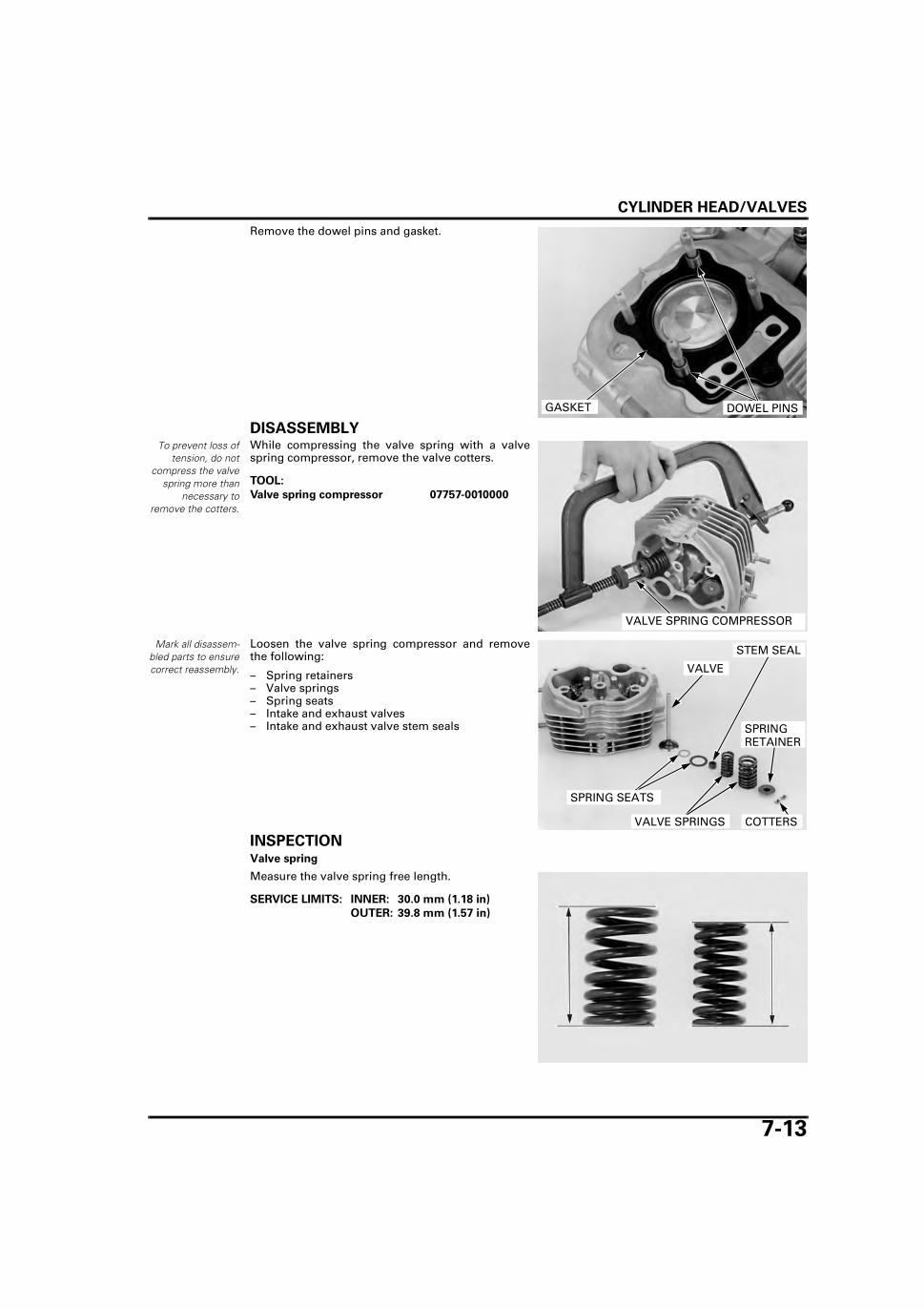
CYLINDER HEAD/VALVES
7-13
Remove the dowel pins and gasket.
DISASSEMBLYTo prevent loss of
tension, do notcompress the valve
spring more thannecessary to
remove the cotters.
While compressing the valve spring with a valvespring compressor, remove the valve cotters.
Mark all disassem-bled parts to ensurecorrect reassembly.
Loosen the valve spring compressor and removethe following:
– Spring retainers– Valve springs– Spring seats– Intake and exhaust valves– Intake and exhaust valve stem seals
INSPECTIONValve spring
Measure the valve spring free length.
DOWEL PINSGASKET
TOOL:
Valve spring compressor 07757-0010000
VALVE SPRING COMPRESSOR
VALVE
SPRING RETAINER
VALVE SPRINGS
STEM SEAL
COTTERS
SPRING SEATS
SERVICE LIMITS: INNER: 30.0 mm (1.18 in)
OUTER: 39.8 mm (1.57 in)

CYLINDER HEAD/VALVES
7-14
Push rod
Check the push rods for bending.Measure the push rods length.
Cylinder head
Remove the carbon deposits from the combustionchamber.
Clean off any gasket materials from the cylinderhead surface.
Check the spark plug hole and valve area for cracks.Check the cylinder head for warpage with a straightedge and a feeler gauge.
Valve
Inspect the valve for trueness, burning, scratches orabnormal stem wear.Measure the valve stem O.D.
Insert each valve into the valve guide and check thevalve movement in the guide.
SERVICE LIMIT: 141.0 mm (5.55 in)
PUSH RODS
Be careful not todamage the gasket
surface.
COMBUSTION CHAMBER
SERVICE LIMIT: 0.05 mm (0.002 in)
SERVICE LIMITS: IN: 5.42 mm (0.213 in)
EX: 5.40 mm (0.213 in)
VALVE

CYLINDER HEAD/VALVES
7-15
Always rotate thereamer clockwise,
never counter-clockwise.
Ream the guides to remove any carbon build-upbefore measuring the guide.
Measure each valve guide I.D. and record it.
Subtract each valve stem O.D. from the correspond-ing guide I.D. to obtain the stem-to-guide clearance.
If the stem-to- guide clearance exceeds the servicelimit, determine if a new guide with standarddimensions would bring the clearance within toler-ance. If so, replace any guides as necessary andream to fit.If the stem-to-guide clearance exceeds the servicelimit with a new guide, also replace the valve.
VALVE GUIDE REPLACEMENTChill the replacement valve guides in the freezer of arefrigerator for about an hour.
Heat the cylinder head to 100°C (212°F) with a hotplate or oven.Do not heat the cylinder head beyond 150°C (300°F).Use temperature indicator sticks, available fromwelding supply stores, to be sure that the cylinderhead is heated to the proper temperature.
Support the cylinder head and drive out the valveguide from the combustion chamber side of the cyl-inder head.
Apply engine oil to the new O-rings.
Take out the new valve guides from the freezer.
Install the O-rings to the new valve guides.
Keep driving in the valve guides from the top of thecylinder head until it is seated.
TOOL:
Valve guide reamer, 5.485 mm 07984-0980001
VALVE GUIDE REAMER
SERVICE LIMIT: IN/EX: 5.50 mm (0.217 in)
SERVICE LIMITS: IN: 0.12 mm (0.005 in)
EX: 0.14 mm (0.006 in)
Inspect and refacethe valve seats
whenever the valveguides are replaced
(page 7-16).
Be sure to wearheavy gloves to
avoid burns whenhandling the heated
cylinder head.
TOOL:
Valve guide driver, 5.35 mm 07742-0010100
VALVE GUIDE DRIVER
Reface the valveseat whenever new
valve guides areinstalled. TOOL:
Valve guide driver, 5.35 mm 07742-0010100
VALVE GUIDE
O-RING

CYLINDER HEAD/VALVES
7-16
Use cutting oil onthe reamer during
this operation. Takecare not to tilt or
lean the reamer inthe guide while
reaming.
After driving in the valve guide, insert the valveguide reamer from the combustion chamber side ofthe cylinder head and always rotate the reamerclockwise.
Clean the cylinder head thoroughly to remove anymetal particles after reaming and reface the valveseat.
VALVE SEAT INSPECTIONClean the intake and exhaust valves thoroughly toremove any carbon deposit.
Apply Prussian Blue light coating to the valve seats.Lap the valves and seats with a rubber hose oranother hand-lapping tool.
Remove the valve and inspect the valve seat face.The valve seat contact should be within the speci-fied width and even all around the circumference.
If the valve seat width is not within specification,reface the valve seat.
Inspect the valve seat face for:
• Uneven seat width:– Bent or collapsed valve stem;
Replace the valve and reface the valve seat. • Damaged face:
– Replace the valve and reface the valve seat.
TOOL:
Valve guide reamer, 5.485 mm 07984-0980001
VALVE GUIDE REAMER
HAND-LAPPING TOOL
STANDARD: 1.2 – 1.5 mm (0.05 – 0.06 in)
SERVICE LIMIT: 2.0 mm (0.08 in)
VALVE SEAT CONTACT WIDTH
UNEVEN SEAT WIDTH DAMAGED FACE

CYLINDER HEAD/VALVES
7-17
The valve cannot beground. If the valve
face is burned orbadly worn or if itcontacts the seatunevenly, replace
the valve.
• Contact area (too low or too high)– Reface the valve seat.
VALVE SEAT REFACINGFollow the refacing
manufacturer’soperating instruc-tions. Be carefulnot to grind the
seat more than nec-essary.
Valve seat cutters/grinders or equivalent valve seatrefacing equipment are recommended to correctworn valve seats.
If the contact area is too high on the valve, the seatmust be lowered using a 32° flat cutter.
If the contact area is too low on the valve, the seatmust be raised using a 60° inner cutter.
Reface the valveseat with a 45° cut-
ter when a valveguide is replaced.
Using a 45° cutter, remove any roughness or irregu-larities from the seat.
TOO LOW TOO HIGH
32°
45°
60°
OLD SEAT WIDTH
OLD SEAT WIDTH
60°
32° CONTACT TOO LOW
CONTACT TOO HIGH
TOOLS:
Valve seat cutter, 33 mm (45° IN) 07780-0010800
Valve seat cutter, 24.5 mm (45° EX) 07780-0010100
Cutter holder, 5.5 mm 07781-0010101
ROUGHNESS

CYLINDER HEAD/VALVES
7-18
Using a 32° cutter, remove the top 1/4 of the exist-ing valve seat material.
Using a 60° cutter, remove the bottom 1/4 of theexisting valve seat material.
Using a 45° cutter, cut the seat to the proper width.
Make sure that all pitting and irregularities areremoved.Refinish if necessary.
After cutting the seat, apply lapping compound tothe valve face, and lap the valve lightly.
• Excessive lapping pressure may deform or dam-age the seat.
• Change the angle of the lapping tool frequentlyto prevent uneven seat wear.
• Do not allow the lapping compound to enter thevalve guides.
After lapping, wash all residual compound off thecylinder head and valve and recheck the seat con-tact.
TOOLS:
Flat cutter, 33 mm (32° IN) 07780-0012900
Flat cutter, 25 mm (32° EX) 07780-0012000
Cutter holder, 5.5 mm 07781-0010101
OLD SEAT WIDTH
32°
TOOLS:
Interior cutter, 30 mm (60° IN) 07780-0014000
Interior cutter, 30 mm (60° EX) 07780-0014000
Cutter holder, 5.5 mm 07781-0010101
60°
OLD SEAT WIDTH
SEAT WIDTH
45°
HAND-LAPPING TOOL
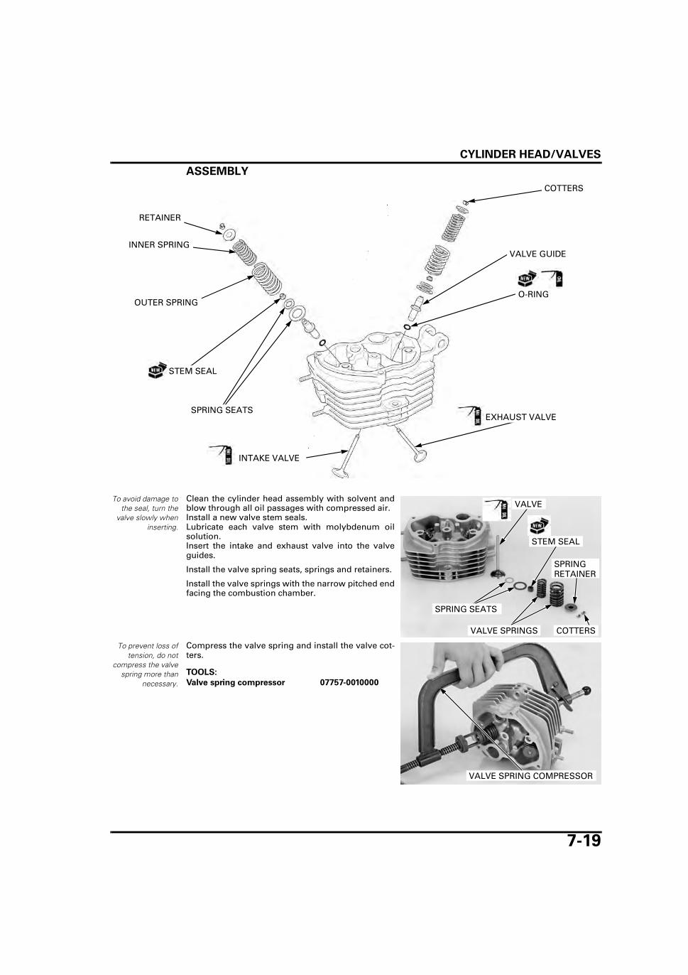
CYLINDER HEAD/VALVES
7-19
ASSEMBLY
To avoid damage tothe seal, turn the
valve slowly wheninserting.
Clean the cylinder head assembly with solvent andblow through all oil passages with compressed air.Install a new valve stem seals.Lubricate each valve stem with molybdenum oilsolution.Insert the intake and exhaust valve into the valveguides.
Install the valve spring seats, springs and retainers.
Install the valve springs with the narrow pitched endfacing the combustion chamber.
To prevent loss oftension, do not
compress the valvespring more than
necessary.
Compress the valve spring and install the valve cot-ters.
RETAINER
STEM SEAL
VALVE GUIDE
INTAKE VALVE
EXHAUST VALVE
INNER SPRING
COTTERS
SPRING SEATS
OUTER SPRINGO-RING
VALVE
SPRING RETAINER
VALVE SPRINGS
STEM SEAL
COTTERS
SPRING SEATS
TOOLS:
Valve spring compressor 07757-0010000
VALVE SPRING COMPRESSOR

CYLINDER HEAD/VALVES
7-20
Support the cylin-der head above the
work bench sur-face to preventvalve damage.
Tap the stems with two plastic hammers to firmlyseat the cotters.
INSTALLATIONDo not allow dust
and dirt to enter theengine.
Clean any gasket material from the cylinder matingsurfaces.
Install the dowel pins and new cylinder head gasket.
Install the cylinder head.
Install the left side cylinder head bolt and new seal-ing washer.
Apply clean engine oil to the cylinder head nutthreads.
Install the new cylinder head washers and nuts.Tighten the fasteners in order as follows.
PLASTIC HAMMERS
DOWEL PINS
GASKET
When installing theleft side cylinder
head bolt, align thehole in the cam fol-lower shaft using a
screwdriver asshown. Install the
bolt but do nottighten it yet.
BOLT SEALING WASHER
CYLINDER HEAD CAM FOLLOWER SHAFT
SCREWDRIVER
Tighten the cylin-der head nuts in acrisscross pattern
in 2 or 3 steps. TORQUES:
Cylinder head nut: 32 N·m (3.3 kgf·m, 24 lbf·ft)Cylinder head bolt: 20 N·m (2.0 kgf·m, 15 lbf·ft)Cylinder bolt: 10 N·m (1.0 kgf·m, 7 lbf·ft)
CYLINDER HEAD
CYLINDER HEAD BOLTWASHERS/NUTS
CYLINDER BOLTS

CYLINDER HEAD/VALVES
7-21
Apply clean engine oil to the ends of the push rods.
Install the push rods.
Install the following:
– Rocker arm holder (page 7-11)– Cylinder head cover (page 7-8)– Engine (page 6-10)
The push rods areinterchangeable.
PUSH RODS

MEMO

8-1
8
8. CYLINDER/PISTON/CAMSHAFT
SYSTEM COMPONENTS ······························ 8-2
SERVICE INFORMATION ······························ 8-3
TROUBLESHOOTING ···································· 8-3
CYLINDER ······················································ 8-4
CAM FOLLOWER/SHAFT ······························8-6
CAMSHAFT·····················································8-7
PISTON··························································8-10

CYLINDER/PISTON/CAMSHAFT
8-2
CYLINDER/PISTON/CAMSHAFT
SYSTEM COMPONENTS

CYLINDER/PISTON/CAMSHAFT
8-3
SERVICE INFORMATION
GENERAL • The engine must be removed from the frame to service the cylinder, piston and camshaft. • Be careful not to damage the mating surfaces when removing the cylinder. Do not strike the cylinder too hard during
removal. • Rocker arm lubricating oil is fed through an oil passage in the cylinder. Clean the oil passage before installing cylinder.
SPECIFICATIONSUnit: mm (in)
TROUBLESHOOTINGCompression too low, hard starting or poor performance at low speed • Leaking cylinder head gasket • Worn, stuck or broken piston ring • Worn or damaged cylinder and piston • Loose spark plug
Compression too high, overheating or knocking • Excessive carbon built-up on piston head or combustion chamber
Excessive smoke • Worn cylinder, piston or piston rings • Improper installation of piston rings • Scored or scratched piston or cylinder wall
Abnormal noise • Worn piston pin or piston pin hole • Worn connecting rod small end • Worn cylinder, piston or piston rings
ITEM STANDARD SERVICE LIMIT
Camshaft Cam lobe height 32.768 – 32.928 (1.2901 – 1.2964) 32.63 (1.285)Camshaft I.D. 14.060 – 14.078 (0.5535 – 0.5543) 14.123 (0.5560)Cam gear shaft O.D. 14.030 – 14.040 (0.5524 – 0.5528) 14.017 (0.5518)Camshaft-to-gear shaft clearance 0.020 – 0.048 (0.0008 – 0.0019) 0.106 (0.0042)Cam follower I.D. 12.000 – 12.018 (0.4724 – 0.4731) 12.03 (0.474)Cam follower shaft O.D. 11.984 – 11.994 (0.4718 – 0.4722) 11.96 (0.471)Cam follower-to-follower shaft clearance
0.006 – 0.034 (0.0002 – 0.0013) 0.07 (0.003)
Cylinder I.D. 56.500 – 56.512 (2.2244 – 2.2249) 56.60 (2.228)Out-of-round – 0.10 (0.004)Taper – 0.10 (0.004)Warpage – 0.05 (0.002)
Piston,piston pin, piston ring
Piston O.D. at 8 (0.3) from bottom 56.470 – 56.490 (2.2232 – 2.2240) 56.40 (2.220)Piston pin hole I.D. 15.002 – 15.008 (0.5906 – 0.5909) 15.04 (0.592)Piston pin O.D. 14.994 – 14.998 (0.5903 – 0.5905) 14.96 (0.589)Piston-to-piston pin clearance 0.004 – 0.014 (0.0002 – 0.0006) 0.02 (0.001)Piston ring end gap Top 0.10 – 0.25 (0.004 – 0.010) 0.5 (0.02)
Second 0.25 – 0.40 (0.010 – 0.016) 0.5 (0.02)Oil (side rail) 0.20 – 0.70 (0.008 – 0.028) –
Piston ring-to-ring groove clearance
Top 0.015 – 0.045 (0.0006 – 0.0018) 0.09 (0.004)Second 0.015 – 0.045 (0.0006 – 0.0018) 0.09 (0.004)
Cylinder-to-piston clearance 0.010 – 0.042 (0.0004 – 0.0017) 0.10 (0.004)Connecting rod small end I.D. 15.010 – 15.022 (0.5909 – 0.5914) 15.06 (0.593)Connecting rod-to-piston pin clearance 0.012 – 0.028 (0.0005 – 0.0011) 0.10 (0.004)

CYLINDER/PISTON/CAMSHAFT
8-4
CYLINDERREMOVALRemove the cylinder head (page 7-12).Remove the cylinder bolts and cylinder.
Be careful not todamage the cylin-
der surface and notto let the dust or
dirt fall into thecrankcase.
Remove the dowel pins and gasket.
INSPECTIONRemove any gasket material from the cylinder sur-face.Check the cylinder for warpage with a straight edgeand a feeler gauge.
Inspect the cylinder bore for scratch, wear or dam-age.Measure the cylinder I.D. in X and Y axis at threelevels.Take the maximum reading to determine the cylin-der wear.
Measure the piston O.D. (page 8-10) and calculatethe cylinder-to-piston clearance.Take a maximum reading to determine the clear-ance.
Do not strike thecylinder too hard
and do not damagethe mating surfacewith a screwdriver.
BOLTS
CYLINDER
DOWEL PINS
GASKET
SERVICE LIMIT: 0.05 mm (0.002 in)
SERVICE LIMIT: 56.60 mm (2.228 in)
SERVICE LIMIT: 0.10 mm (0.004 in)
CYLINDER

CYLINDER/PISTON/CAMSHAFT
8-5
Calculate the taper and out of round at three levelsin an X and Y axis.Take the maximum reading to determine the taper.
INSTALLATIONClean off any gasket material from the crankcasesurface.
Apply liquid sealant (THREE BOND #1141 or equiva-lent) to the cylinder-to-crankcase hatched area asshown.
Install the dowel pins and new gasket.
Apply clean engine oil to the cylinder inner surface,piston rings/grooves and piston.
Install the cylinder while compressing the pistonrings.
Taper: 0.10 mm (0.004 in)
Out-of-round: 0.10 mm (0.004 in)TOP
MIDDLE
BOTTOM
X
Y
5 mm (0.2 in)10 mm (0.4 in)
GASKET
DOWEL PINS
Be careful not todamage the piston
ring and cylinderwall while installa-
tion.
CYLINDER
PISTON/RINGS

CYLINDER/PISTON/CAMSHAFT
8-6
Install the cylinder bolts.
Install the following:
– Cylinder head (page 7-20)– Rocker arm (page 7-11)– Cylinder head cover (page 7-8)– Engine (page 6-10)
CAM FOLLOWER/SHAFT
REMOVALRemove the cylinder (page 8-4).
Remove the cam follower shaft using a screwdriveras shown.
Remove the cam followers and wave washer.Remove the O-ring from the cam follower shaft.
INSPECTIONCheck the cam followers for wear, damage orclogged oil holes.
If any cam follower requires servicing or replace-ment, inspect the cam lobe for scoring, chipping orexcessive wear.
Measure the cam follower I.D.
Measure the cam follower shaft O.D.
Calculate the cam follower-to-follower shaft clear-ance.
BOLTS
CYLINDER
SCREWDRIVER
CAM FOLLOWER SHAFT
CAM FOLLOWER SHAFT
O-RING
WAVE WASHER
CAM FOLLOWERS
SERVICE LIMIT: 12.03 mm (0.474 in)
SERVICE LIMIT: 11.96 mm (0.471 in)
SERVICE LIMIT: 0.07 mm (0.003 in)
CAM FOLLOWER SHAFT WAVE WASHER
CAM FOLLOWERS

CYLINDER/PISTON/CAMSHAFT
8-7
INSTALLATIONApply molybdenum oil to the cam follower shaftsliding surfaces.Install a new O-ring onto the cam follower shaftgroove.Install the wave washer, cam followers and cam fol-lower shaft.
Install the following:
– Cylinder (page 8-5)– Cylinder head (page 7-20)– Rocker arm (page 7-11)– Cylinder head cover (page 7-8)– Engine (page 6-10)
CAMSHAFT
REMOVALRemove the following:
– Cylinder (page 8-4)– Flywheel (page 10-6)
Remove the bolt and spring stopper plate.
Remove the camshaft spring.
Remove the cam gear shaft using the pliers.Remove the camshaft/cam gear.
Remove the O-ring from the cam gear shaft.
CAM FOLLOWER SHAFT
O-RING
WAVE WASHER
CAM FOLLOWERS
BOLT
SPRING STOPPER PLATE
CAMSHAFT SPRING
CAMSHAFT/CAM GEARO-RING
CAM GEAR SHAFT
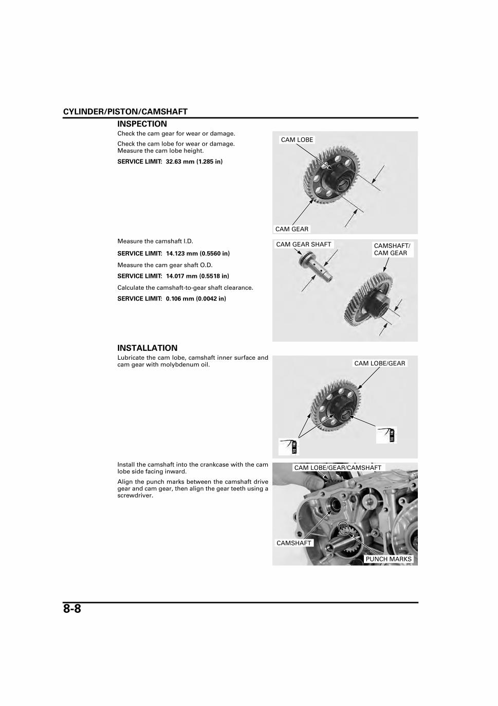
CYLINDER/PISTON/CAMSHAFT
8-8
INSPECTIONCheck the cam gear for wear or damage.
Check the cam lobe for wear or damage.Measure the cam lobe height.
Measure the camshaft I.D.
Measure the cam gear shaft O.D.
Calculate the camshaft-to-gear shaft clearance.
INSTALLATIONLubricate the cam lobe, camshaft inner surface andcam gear with molybdenum oil.
Install the camshaft into the crankcase with the camlobe side facing inward.
Align the punch marks between the camshaft drivegear and cam gear, then align the gear teeth using ascrewdriver.
SERVICE LIMIT: 32.63 mm (1.285 in)
CAM LOBE
CAM GEAR
SERVICE LIMIT: 14.123 mm (0.5560 in)
SERVICE LIMIT: 14.017 mm (0.5518 in)
SERVICE LIMIT: 0.106 mm (0.0042 in)
CAMSHAFT/CAM GEAR
CAM GEAR SHAFT
CAM LOBE/GEAR
CAM LOBE/GEAR/CAMSHAFT
CAMSHAFT
PUNCH MARKS
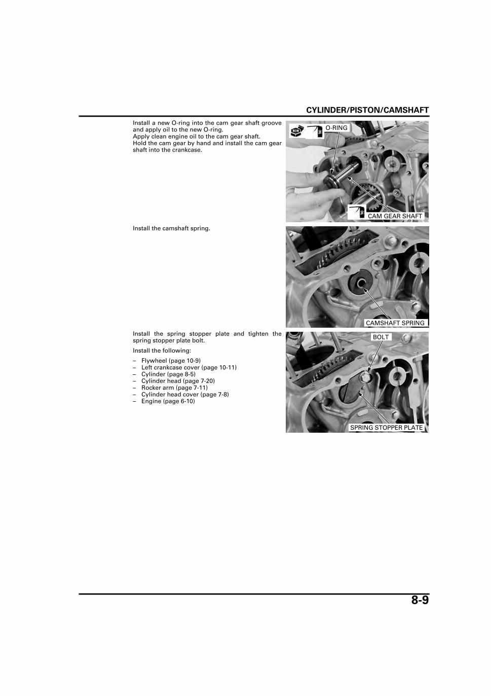
CYLINDER/PISTON/CAMSHAFT
8-9
Install a new O-ring into the cam gear shaft grooveand apply oil to the new O-ring.Apply clean engine oil to the cam gear shaft.Hold the cam gear by hand and install the cam gearshaft into the crankcase.
Install the camshaft spring.
Install the spring stopper plate and tighten thespring stopper plate bolt.
Install the following:
– Flywheel (page 10-9)– Left crankcase cover (page 10-11)– Cylinder (page 8-5)– Cylinder head (page 7-20)– Rocker arm (page 7-11)– Cylinder head cover (page 7-8)– Engine (page 6-10)
O-RING
CAM GEAR SHAFT
CAMSHAFT SPRING
BOLT
SPRING STOPPER PLATE

CYLINDER/PISTON/CAMSHAFT
8-10
PISTONREMOVALRemove the cylinder (page 8-4).
Remove the piston pin clip with pliers.Remove the piston pin and piston.
Spread each piston ring and remove it by lifting itup at a point just opposite the gap.
Clean carbon deposits from the piston ring grooveswith a ring that will be discarded. Never use a wire brush because it scratches thegrooves.
INSPECTIONPush the rings into
the cylinder withthe top of the pis-
ton to be sure theyare inserted
squarely in the cyl-inder.
Insert each piston ring into the cylinder using thepiston head and measure the ring end gap in thecylinder at a point 10 mm (0.4 in) from the bottom.
Place a clean shoptowel in the crank-
case to prevent thepiston pin clips or
other parts fromfalling into the
crankcase.
PISTON PIN
PISTON PISTON PIN CLIP
Do not damage thepiston ring by
spreading the endstoo far.
Be careful not todamage the piston
when removing thepiston ring.
PISTON RING
PISTON RING
SERVICE LIMIT:
Top/second: 0.5 mm (0.02 in)
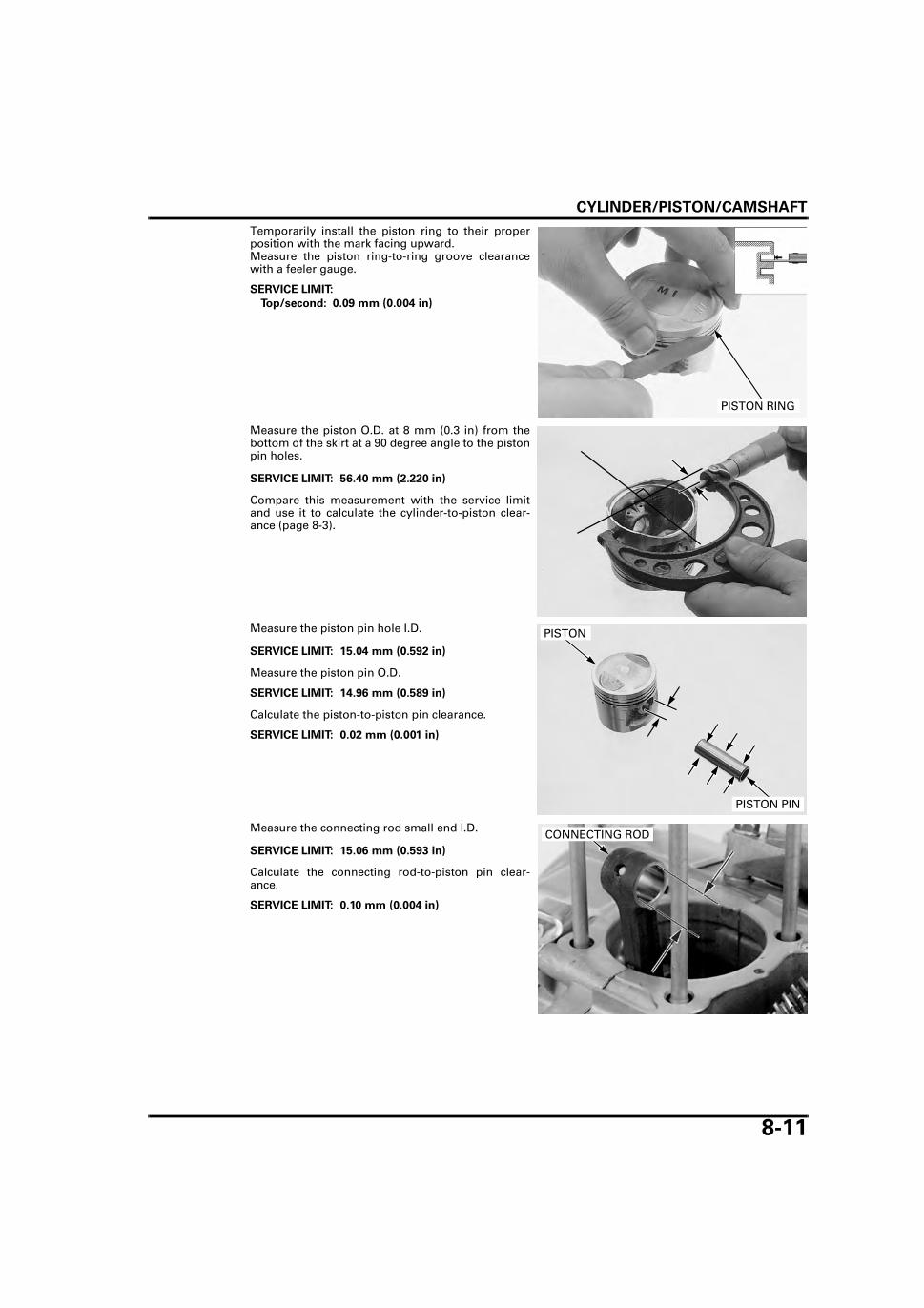
CYLINDER/PISTON/CAMSHAFT
8-11
Temporarily install the piston ring to their properposition with the mark facing upward.Measure the piston ring-to-ring groove clearancewith a feeler gauge.
Measure the piston O.D. at 8 mm (0.3 in) from thebottom of the skirt at a 90 degree angle to the pistonpin holes.
Compare this measurement with the service limitand use it to calculate the cylinder-to-piston clear-ance (page 8-3).
Measure the piston pin hole I.D.
Measure the piston pin O.D.
Calculate the piston-to-piston pin clearance.
Measure the connecting rod small end I.D.
Calculate the connecting rod-to-piston pin clear-ance.
SERVICE LIMIT:
Top/second: 0.09 mm (0.004 in)
PISTON RING
SERVICE LIMIT: 56.40 mm (2.220 in)
SERVICE LIMIT: 15.04 mm (0.592 in)
SERVICE LIMIT: 14.96 mm (0.589 in)
SERVICE LIMIT: 0.02 mm (0.001 in)
PISTON
PISTON PIN
SERVICE LIMIT: 15.06 mm (0.593 in)
SERVICE LIMIT: 0.10 mm (0.004 in)
CONNECTING ROD

CYLINDER/PISTON/CAMSHAFT
8-12
INSTALLATIONClean the piston head, ring land and skirt.
Carefully install the piston rings with the markingfacing upward.
• Be careful not to damage the piston and pistonrings during installation.
• Do not interchange the top ring with the secondring.
Stagger the piston ring end gaps at a 120-degreeangle from each other as shown.
• When installing the oil ring, install the spacerfirst and then the side rails.
• Do not align the gaps of the oil ring side rails.
After installation, the piston rings should be free torotate in the grooves.
Place a clean shoptowel in the crank-
case to prevent thegasket or other
parts from fallinginto the crankcase.Do not damage thecylinder gasket sur-
face.
Remove any gasket material from the cylinder gas-ket surface of the crankcase.
Apply molybdenum oil solution to the piston pinouter surface.
Place a clean shop towel in the crankcase to preventthe piston pin clips or other parts from falling intothe crankcase.
Install the piston with the "IN" mark facing the intakeside.
Install the piston pin and new piston pin clips.
Install the following:
– Cylinder (page 8-5)– Cylinder head (page 7-20)– Rocker arm (page 7-11)– Cylinder head cover (page 7-8)– Engine (page 6-10)
Insert the outsidesurface of the pis-
ton ring into theproper ring grooveand rotate the ring
in the groove tomake sure that the
ring has a free fitaround the piston’s
circumference.TOP RING
TOP RING
SECOND RING
SIDE RAILS
SECOND RING
SPACER
A
A
A: 20 mm (0.8 in) OR MORE GAP
120°
120°
120°
CYLINDER GASKET SURFACE
Do not reuse pistonpin clips. Do not
align the piston pinclip end gap with
the piston cut-out.
PISTON
PISTON PIN
PISTON PIN CLIP
"IN" MARK

9-1
9
9. CLUTCH/GEARSHIFT LINKAGE
SYSTEM COMPONENTS ······························ 9-2
SERVICE INFORMATION ······························ 9-3
TROUBLESHOOTING ···································· 9-4
RIGHT CRANKCASE COVER REMOVAL······ 9-5
CLUTCH LIFTER ARM ····································9-6
CLUTCH···························································9-6
GEARSHIFT LINKAGE ··································9-11
RIGHT CRANKCASE COVERINSTALLATION·············································9-14

CLUTCH/GEARSHIFT LINKAGE
9-2
CLUTCH/GEARSHIFT LINKAGE
SYSTEM COMPONENTS
12 N·m (1.2 kgf·m, 9 lbf·ft)
5 N·m (0.5 kgf·m, 3.7 lbf·ft)
54 N·m (5.5 kgf·m, 40 lbf·ft)
27 N·m (2.8 kgf·m, 20 lbf·ft)
12 N·m (1.2 kgf·m, 9 lbf·ft)
12 N·m (1.2 kgf·m, 9 lbf·ft)

CLUTCH/GEARSHIFT LINKAGE
9-3
SERVICE INFORMATIONGENERAL • This section covers maintenance of the clutch, gearshift linkage and right crankcase cover. These services can be per-
formed with the engine installed in the frame. • Engine oil viscosity and level have an effect on clutch disengagement. When the clutch does not disengage or the
motorcycle creeps with clutch disengaged, inspect the engine oil and oil level before servicing the clutch system.
SPECIFICATIONSUnit: mm (in)
TORQUE VALUES
TOOLS
ITEM STANDARD SERVICE LIMIT
Clutch lever free play 10 – 20 (0.4 – 0.8) –Clutch Spring free length 35.50 (1.398) 34.20 (1.346)
Disc thickness 2.90 – 3.00 (0.114 – 0.181) 2.6 (0.10)Plate warpage – 0.20 (0.008)
Clutch lifter plate bolt 12 N·m (1.2 kgf·m, 9 lbf·ft)Shift drum stopper arm bolt 12 N·m (1.2 kgf·m, 9 lbf·ft)Oil filter rotor lock nut 54 N·m (5.5 kgf·m, 40 lbf·ft) Apply oil to the threads and seating surface.Oil filter rotor cover screw 5 N·m (0.5 kgf·m, 3.7 lbf·ft)Gearshift pedal pinch bolt 12 N·m (1.2 kgf·m, 9 lbf·ft)Kickstarter pedal pinch bolt 27 N·m (2.8 kgf·m, 20 lbf·ft)
Lock nut wrench, 20 x 24 mm07716-0020100
Extension bar07716-0020500
Gear holder07724-0010200

CLUTCH/GEARSHIFT LINKAGE
9-4
TROUBLESHOOTINGFaulty clutch operation can usually be corrected by adjusting the free play.
Clutch lever difficult to pull in • Damaged, kinked or dirty clutch cable • Improperly routed clutch cable • Damaged clutch lifter mechanism • Faulty clutch lifter plate bearing
Clutch will not disengage or motorcycle creeps with clutch disengaged • Excessive clutch lever free play • Clutch plate warped • Oil level too high, improper oil viscosity, or additive used • Check for oil additive
Clutch slips • Clutch lifter sticking • Worn clutch discs • Weak clutch springs • Incorrect clutch adjustment • Check for oil additive
Hard to shift • Misadjusted clutch lever free play • Damaged or bent shift fork • Bent shift fork shaft • Incorrect engine oil viscosity • Incorrect gearshift spindle assembly • Damaged shift drum guide grooves
Transmission jumps out of gear • Worn shift drum stopper arm • Worn or broken gearshift spindle return spring • Bent shift fork shaft • Damaged shift drum guide grooves • Worn gear dogs or dog holes
Gearshift pedal will not return • Weak or broken gearshift spindle return spring • Bent gearshift spindle

CLUTCH/GEARSHIFT LINKAGE
9-5
RIGHT CRANKCASE COVER REMOVALREMOVALDrain engine oil into the clean container (page 3-10).Remove the muffler (page 2-8).Remove the footpeg bar assembly (page 2-8).
Loosen the clutch cable lock nut and clutch cableadjusting nut.
Release the clutch cable from the stay and discon-nect the clutch cable end from the lifter arm.
Remove the bolt and kickstarter pedal.
Loosen the bolts ina crisscross pattern
in 2 or 3 steps.
Remove the bolts and right crankcase cover.
Remove the gasket and dowel pins.
LOCK NUT
ADJUSTING NUT
STAYLIFTER ARM
CLUTCH CABLE
KICKSTARTER PEDAL
BOLT
RIGHT CRANKCASE COVERBOLTS
GASKET
DOWEL PINS

CLUTCH/GEARSHIFT LINKAGE
9-6
CLUTCH LIFTER ARM
REMOVAL/INSTALLATIONRemove the cotter pin and remove the clutch lifterarm and return spring.
Visually inspect the clutch arm for bending or dam-age.
Install the clutch arm on the right crankcase cover inthe reverse order of removal with a new cotter pin.
CLUTCH
REMOVALRemove the right crankcase cover (page 9-5).
Remove the screws, oil filter rotor cover and gasket.
Hold the primary drive/driven gear with gear holderand remove the oil filter rotor lock nut by using thespecial tool.
Remove the lock washer and oil filter rotor.
Remove the clutch lifter rod and clutch lifter guidepin.Remove the clutch bolts, clutch lifter plate andclutch spring.
COTTER PIN
CLUTCH LIFTER ARM
RETURN SPRING
COVER/GASKET
SCREWS
TOOLS:
Gear holder 07724-0010200
Lock nut wrench, 20 x 24 mm 07716-0020100
Extension bar 07716-0020500
LOCK NUT WRENCH
OIL FILTER ROTOR
GEAR HOLDER
LOCK NUT/WASHER
Loosen the bolts ina crisscross pattern
in 2 or 3 steps.
BOLTS/SPRINGS LIFTER PLATE
LIFTER ROD GUIDE PIN

CLUTCH/GEARSHIFT LINKAGE
9-7
Remove the following:
– Snap ring– Clutch center– Clutch discs– Clutch plates– Pressure plate
Rotate and align the spline washer teeth with main-shaft grooves.Remove the spline washer and clutch outer.Remove the primary drive gear.
INSPECTIONClutch lifter rod/lifter guide pin
Visually inspect the clutch lifter rod and lifter guidepin for wear or damage.
Clutch lifter bearing
Turn the inner race of the lifter bearing with yourfinger.The bearing should turn smoothly and quietly.Also check that the outer race of the bearing fitstightly in the lifter plate.Replace the bearing if the inner race does not turnsmoothly, quietly, or if the outer race fits loosely inthe lifter plate.
CLUTCH CENTER
SNAP RINGCLUTCH DISCS/PLATES
PRESSURE PLATE
SPLINE WASHER
PRIMARY DRIVE GEAR
CLUTCH OUTER
MAINSHAFT
LIFTER ROD
LIFTER GUIDE PIN
LIFTER BEARING
LIFTER PLATE

CLUTCH/GEARSHIFT LINKAGE
9-8
Clutch spring
Replace the clutchsprings as a set.
Measure the clutch spring free length.
Clutch disc
Replace the clutchdiscs and plates as
a set.
Check the clutch discs for signs of scoring or discol-oration.Measure the thickness of each disc.
Clutch plate
Replace the clutchdiscs and plates as
a set.
Check the plate for discoloration.Check the clutch plate for warpage on a surfaceplate by using a feeler gauge.
Clutch outer
Check the slots in the clutch outer for nicks, cuts orindentations made by the clutch discs.
SERVICE LIMIT: 34.20 mm (1.346 in)
SERVICE LIMIT: 2.6 mm (0.10 in)
SERVICE LIMIT: 0.20 mm (0.008 in)
CLUTCH OUTER
SLOT
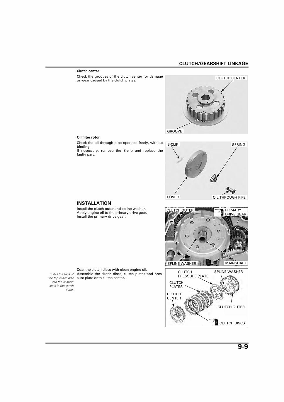
CLUTCH/GEARSHIFT LINKAGE
9-9
Clutch center
Check the grooves of the clutch center for damageor wear caused by the clutch plates.
Oil filter rotor
Check the oil through pipe operates freely, withoutbinding. If necessary, remove the B-clip and replace thefaulty part.
INSTALLATIONInstall the clutch outer and spline washer.Apply engine oil to the primary drive gear.Install the primary drive gear.
Coat the clutch discs with clean engine oil.Assemble the clutch discs, clutch plates and pres-sure plate onto clutch center.
GROOVE
CLUTCH CENTER
OIL THROUGH PIPE
SPRING
COVER
B-CLIP
SPLINE WASHER
PRIMARY DRIVE GEAR
CLUTCH OUTER
MAINSHAFT
Install the tabs ofthe top clutch disc
into the shallowslots in the clutch
outer.
SPLINE WASHERCLUTCH PRESSURE PLATE
CLUTCH CENTER
CLUTCH PLATES
CLUTCH OUTER
CLUTCH DISCS

CLUTCH/GEARSHIFT LINKAGE
9-10
Install the clutch assembly to the mainshaft.Install the snap ring into the mainshaft groove.
Install the clutch springs, lifter plate and bolts.
Tighten the lifter plate bolts in a crisscross patternin several steps.
Apply clean engine oil to the clutch lifter rod.
Install the clutch lifter guide pin and clutch lifter rod.
Install the lockwasher with its
"OUT SIDE" markfacing out.
Clean and apply engine oil to the oil filter rotor theninstall the oil filter rotor and lock washer onto thecrankshaft.Apply engine oil to the threads and seating surfaceof the lock nut and install it with the chamfered sidefacing in.
Hold the primary drive and driven gear with a gearholder and tighten the oil filter rotor lock nut byusing the special tools.
SNAP RING
CLUTCH ASSEMBLY
TORQUE: 12 N·m (1.2 kgf·m, 9 lbf·ft)
BOLTS, SPRINGSLIFTER PLATE
GUIDE PINLIFTER ROD
LOCK WASHER
OIL FILTER ROTOR
LOCK NUT
TOOLS:
Gear holder 07724-0010200
Lock nut wrench, 20 x 24 mm 07716-0020100
Extension bar 07716-0020500
TORQUE: 54 N·m (5.5 kgf·m, 40 lbf·ft)
LOCK NUT WRENCH
GEAR HOLDER
OIL FILTER ROTOR

CLUTCH/GEARSHIFT LINKAGE
9-11
Install a new gasket onto the filter rotor cover.Apply engine oil to the oil through sliding area.
Install the filter rotor cover and tighten the screws.
Install the right crankcase cover (page 9-14)
Check that the clutch operates properly.
GEARSHIFT LINKAGE
REMOVALRemove the following:
– Clutch (page 9-6)– Oil pump (page 4-5)
Remove the bolt and gearshift pedal.
Pull the gearshift spindle out of the crankcase.
COVER GASKET
OIL THROUGH
TORQUE: 5 N·m (0.5 kgf·m, 3.7 lbf·ft)
COVER
SCREWS
BOLT
GEARSHIFT PEDAL
GEARSHIFT SPINDLE

CLUTCH/GEARSHIFT LINKAGE
9-12
Remove the following:
– Stopper plate bolt– Shift drum stopper plate– Dowel pin from the shift drum– Stopper arm bolt– Stopper arm– Washer– Return spring
INSPECTIONCheck the gearshift spindle for wear or bend.Check the spindle plate for wear, damage or defor-mation.Check the return spring for fatigue or damage.
INSTALLATIONInstall the dowel pin into the hole of the shift drum.
Install the return spring, washer, stopper arm andbolt, then tighten the bolt to the specified torque.
Hold the stopper arm using a screwdriver and installthe stopper plate by aligning the pin hole with thedowel pin.
STOPPER PLATE BOLT
STOPPER ARM BOLT
STOPPER PLATE/DOWEL PIN
STOPPER ARMRETURN SPRING/WASHER
PLATE
RETURN SPRING
GEARSHIFT SPINDLE
TORQUE: 12 N·m (1.2 kgf·m, 9 lbf·ft)
STOPPER ARM
RETURN SPRING/WASHER STOPPER ARM BOLT
DOWEL PIN
STOPPER PLATE
SCREWDRIVER STOPPER ARM
HOLE DOWEL PIN

CLUTCH/GEARSHIFT LINKAGE
9-13
Install and tighten the stopper plate bolt.
Install the washer onto the gearshift spindle.
Install the gearshift spindle with the spindle returnspring attached to the lug on the crankcase.
Install the gearshift pedal and tighten the bolt to thespecified torque.
Install the following:
– Oil pump (page 4-9)– Clutch (page 9-9)
STOPPER PLATE BOLT
SPINDLE WASHERSPRING
TORQUE: 12 N·m (1.2 kgf·m, 9 lbf·ft)
BOLT
GEARSHIFT PEDAL

CLUTCH/GEARSHIFT LINKAGE
9-14
RIGHT CRANKCASE COVERINSTALLATION
Be careful not todamage the mating
surfaces.
Clean off any gasket material from the mating sur-faces of the right crankcase and cover.
Install the dowel pins and new gasket.
Install the right crankcase cover, and tighten thebolts in a crisscross pattern in 2 - 3 steps.
Install the kickstarter pedal and tighten the bolt tothe specified torque.
Connect the clutch cable end to the lifter arm andset the clutch cable to the stay.
Install the footpeg bar (page 2-8)Install the muffler (page 2-9).Adjust the clutch lever free play (page 3-18).Fill the crankcase with the recommended engine oil(page 3-10).
GASKET
DOWEL PINS
RIGHT CRANKCASE COVERBOLTS
TORQUE: 27 N·m (2.8 kgf·m, 20 lbf·ft)
KICKSTARTER PEDAL
BOLT
STAYLIFTER ARM
CLUTCH CABLE

10-1
10
10. ALTERNATOR/STARTER CLUTCH
SYSTEM COMPONENTS ···························· 10-2
SERVICE INFORMATION ···························· 10-3
TROUBLESHOOTING ·································· 10-3
LEFT CRANKCASE COVER REMOVAL ······ 10-4
STATOR/IGNITION PULSE GENERATOR·· 10-5
FLYWHEEL REMOVAL ·································10-6
STARTER CLUTCH ······································10-7
FLYWHEEL INSTALLATION·························10-9
LEFT CRANKCASE COVER INSTALLATION···········································10-11

ALTERNATOR/STARTER CLUTCH
10-2
ALTERNATOR/STARTER CLUTCH
SYSTEM COMPONENTS
74 N·m (7.5 kgf·m, 55 lbf·ft)
12 N·m (1.2 kgf·m, 9 lbf·ft)
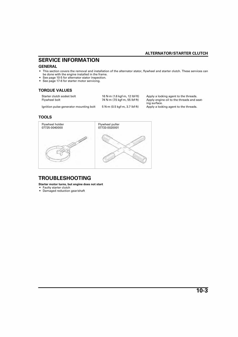
ALTERNATOR/STARTER CLUTCH
10-3
SERVICE INFORMATIONGENERAL • This section covers the removal and installation of the alternator stator, flywheel and starter clutch. These services can
be done with the engine installed in the frame. • See page 10-5 for alternator stator inspection. • See page 17-6 for starter motor servicing.
TORQUE VALUES
TOOLS
TROUBLESHOOTINGStarter motor turns, but engine does not start • Faulty starter clutch • Damaged reduction gear/shaft
Starter clutch socket bolt 16 N·m (1.6 kgf·m, 12 lbf·ft) Apply a locking agent to the threads.Flywheel bolt 74 N·m (7.5 kgf·m, 55 lbf·ft) Apply engine oil to the threads and seat-
ing surface.Ignition pulse generator mounting bolt 5 N·m (0.5 kgf·m, 3.7 lbf·ft) Apply a locking agent to the threads.
Flywheel holder07725-0040000
Flywheel puller07733-0020001

ALTERNATOR/STARTER CLUTCH
10-4
LEFT CRANKCASE COVER REMOVALRemove the left side cover (page 2-3).
Disconnect the following:
– Yellow and Pink alternator wire connectors– Black/Red exciter coil wire connector– Green/White and Blue/Yellow ignition pulse gen-
erator wire connectors
Remove the left crankcase rear cover (page 6-4).
Remove the bolts and starter reduction gear cover. Remove the bolt and wire guide plate.
Release the alternator/ignition pulse generator wirefrom the clamp.
Remove the reduction gear shaft and starter reduc-tion gear.
Loosen the left crankcase cover bolts in a crisscrosspattern in several steps.
Remove the left crankcase cover bolts and cover.
IGNITION PULSE GENERATOR WIRE CONNECTORS
ALTERNATOR WIRE CONNECTORS
EXCITER COIL WIRE CONNECTOR
BOLTS
GEAR COVER
BOLT/PLATE
CLAMP
SHAFT
REDUCTION GEAR
The left crankcasecover (stater) is
magneticallyattached to the fly-
wheel, be carefulwhen removing the
cover.
LEFT CRANKCASE COVER
BOLTS

ALTERNATOR/STARTER CLUTCH
10-5
Remove the dowel pins and gasket.
STATOR/IGNITION PULSE GENERATOR
REMOVALRemove the left crankcase cover (page 10-4).
Remove the following:
– Grommet– Two mounting bolts– Ignition pulse generator– Three socket bolts– Stator
INSTALLATIONInstall the stator.Install the three socket bolts and tighten them.
Apply liquid sealant to the wire grommet seatingsurface and install the grommet into the groove.
Install the ignition pulse generator.
Apply a locking agent to the two mounting boltthreads.
Install the mounting bolts and tighten them to thespecified torque.
DOWEL PINS
GASKET
SOCKET BOLTS
IGNITION PULSE GENERATOR
STATOR
GROMMET
MOUNTING BOLTS
TORQUE: 5 N·m (0.5 kgf·m, 3.7 lbf·ft)
SOCKET BOLTSSTATOR
GROMMET
IGNITION PULSE GENERATOR
MOUNTING BOLTS

ALTERNATOR/STARTER CLUTCH
10-6
FLYWHEEL REMOVALRemove the left crankcase cover (page 10-4).
Remove the starter idle gear, shaft and washers.
Remove the bolt and stopper plate.
Hold the flywheel with the flywheel holder andremove the flywheel bolt.
Remove the flywheel using the flywheel puller.
IDLE GEAR
SHAFT WASHERS
BOLT/STOPPER PLATE
TOOL:
Flywheel holder 07725-0040000
FLYWHEEL HOLDER BOLT
TOOL:
Flywheel puller 07733-0020001
FLYWHEEL PULLERFLYWHEEL

ALTERNATOR/STARTER CLUTCH
10-7
When removing thewoodruff key, be
careful not to dam-age the key groove
and crankshaft.
Remove the woodruff key.
STARTER CLUTCH
DISASSEMBLYRemove the flywheel (page 10-6).
Remove the starter driven gear from the flywheelwhile turning the driven gear counterclockwise.
Remove the starter clutch bolts while holding theflywheel with a flywheel holder.
Remove the starter clutch assembly from the fly-wheel.
WOODRUFF KEY
STARTER DRIVEN GEAR
TOOL:
Flywheel holder 07725-0040000
BOLTS
FLYWHEEL HOLDER
STARTER CLUTCH ASSEMBLY
FLYWHEEL
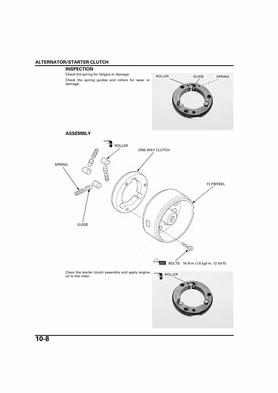
ALTERNATOR/STARTER CLUTCH
10-8
INSPECTIONCheck the spring for fatigue or damage.
Check the spring guides and rollers for wear ordamage.
ASSEMBLY
Clean the starter clutch assembly and apply engineoil to the roller.
SPRINGROLLER GUIDE
ONE-WAY CLUTCH
SPRING
ROLLER
GUIDE
FLYWHEEL
16 N·m (1.6 kgf·m, 12 lbf·ft)BOLTS
ROLLER

ALTERNATOR/STARTER CLUTCH
10-9
Install the starter clutch assembly to the flywheel,aligning the bolt hole of cover, starter clutch and fly-wheel.
Hold the flywheel using the flywheel holder.
Clean and apply a locking agent to the starter clutchbolt threads.Install and tighten the starter clutch socket bolts tothe specified torque.
Apply clean engine oil to the starter driven gearteeth.
Install the starter driven gear to the flywheel whileturning the driven gear counterclockwise.
Make sure that the starter driven gear turns counter-clockwise smoothly and does not turn clockwise.
Install the flywheel (page 10-9).
FLYWHEEL INSTALLATIONWhen installing the
woodruff key, becareful not to dam-age the key groove
and crankshaft.
Clean any oil from the crankshaft taper.
Install the woodruff key.
STARTER CLUTCH ASSEMBLY
FLYWHEEL
TOOL:
Flywheel holder 07725-0040000
TORQUE: 16 N·m (1.6 kgf·m, 12 lbf·ft)
BOLTS
FLYWHEEL HOLDER
STARTER DRIVEN GEAR
WOODRUFF KEY

ALTERNATOR/STARTER CLUTCH
10-10
Install the flywheel, aligning the woodruff key onthe crankshaft with flywheel keyway.
Apply clean engine oil to the flywheel bolt threadsand seating surface.
Install the washer and bolt.
Hold the flywheel with the flywheel holder, tightenthe bolt to the specified torque.
Install the stopper plate and tighten the bolt.
Apply clean engine oil to the starter idle gear andshaft.Install the starter idle gear, shaft and washers.
Install the left crankcase cover (page 10-11).
FLYWHEEL
Align
TOOL:
Flywheel holder 07725-0040000
TORQUE: 74 N·m (7.5 kgf·m, 55 lbf·ft)
FLYWHEEL HOLDER BOLT
BOLT/STOPPER PLATE
STARTER IDLE GEAR
SHAFT
WASHERS

ALTERNATOR/STARTER CLUTCH
10-11
LEFT CRANKCASE COVER INSTALLATION
Apply clean engine oil to the new O-ring and installit to the starter motor.
Install the new gasket and dowel pins.
The left crankcasecover (stator) is
magneticallyattached to the fly-
wheel, be carefulwhen installing.
Install the left crankcase cover and tighten the bolts.
Apply clean engine oil to the starter reduction gearand shaft.
Install the reduction gear shaft and starter reductiongear by aligning the shaft boss with the crankcasecover groove.
O-RING
DOWEL PINS
GASKET
LEFT CRANKCASE COVER
BOLTS
Align
STARTER REDUCTION GEAR/SHAFT

ALTERNATOR/STARTER CLUTCH
10-12
Apply clean engine oil to the new O-ring and installit to the starter reduction gear cover.
Install the starter reduction gear cover to the leftcrankcase cover.
Install and tighten the gear cover bolts.
Route the alternator/ignition pulse generator wire inthe left crankcase groove and install the wire guideplate and the bolt.
Set the alternator/ignition pulse generator wire tothe clamp.
Install the left crankcase rear cover (page 6-5).
Connect the following:
– Yellow and Pink alternator wire connectors– Black/Red exciter coil wire connector– Green/White and Blue/Yellow ignition pulse gen-
erator wire connectors
Install the left side cover (page 2-3).
O-RING
BOLTS
GEAR COVER
BOLT/PLATE
CLAMP
IGNITION PULSE GENERATOR WIRE CONNECTORS
ALTERNATOR WIRE CONNECTORS
EXCITER COIL WIRE CONNECTOR

11-1
11
11. CRANKSHAFT/TRANSMISSION/KICKSTARTER
SYSTEM COMPONENTS ···························· 11-2
SERVICE INFORMATION ···························· 11-3
TROUBLESHOOTING ·································· 11-5
CRANKCASE SEPARATION························ 11-6
CRANKSHAFT···············································11-7
TRANSMISSION···········································11-8
KICKSTARTER ············································11-14
CRANKCASE ASSEMBLY ··························11-19

CRANKSHAFT/TRANSMISSION/KICKSTARTER
11-2
CRANKSHAFT/TRANSMISSION/KICKSTARTER
SYSTEM COMPONENTS
13 N·m (1.3 kgf·m, 10 lbf·ft)

CRANKSHAFT/TRANSMISSION/KICKSTARTER
11-3
SERVICE INFORMATIONGENERAL • The crankcase halves must be separated to service the transmission, crankshaft and kickstarter. To service these parts,
the engine must be removed from the frame (page 6-6). • Be careful not to damage the crankcase mating surfaces when servicing.
SPECIFICATIONSUnit: mm (in)
TORQUE VALUE
ITEM STANDARD SERVICE LIMIT
Crankshaft Connecting rod side clearance 0.10 – 0.30 (0.004 – 0.012) 0.5 (0.02)Connecting rod radial clearance 0.008 – 0.018 (0.0003 – 0.0007) 0.05 (0.002)Runout – 0.02 (0.001)
Transmission Gear I.D. M3, M5 20.020 – 20.041 (0.7882 – 0.7890) 20.07 (0.790)C1 19.520 – 19.541 (0.7685 – 0.7693) 19.57 (0.770)C2 22.000 – 22.021 (0.8661 – 0.8670) 22.05 (0.868)C4 20.020 – 20.041 (0.7882 – 0.7890) 20.07 (0.790)
Bushing O.D. C1 19.479 – 19.500 (0.7669 – 0.7677) 19.43 (0.765)Bushing I.D. C1 16.516 – 16.534 (0.6502 – 0.6509) 16.60 (0.654)Gear-to-bushing clear-ance
C1 0.020 – 0.062 (0.0008 – 0.0024) 0.10 (0.004)
Mainshaft O.D. M3 19.959 – 19.980 (0.7858 – 0.7866) 19.91 (0.784)Countershaft O.D. C1 16.466 – 16.484 (0.6483 – 0.6490) 16.41 (0.646)
C2 21.959 – 21.980 (0.8645 – 0.8654) 21.91 (0.863)C4 19.959 – 19.980 (0.7858 – 0.7866) 19.91 (0.784)
Gear-to-shaft clear-ance
M3 0.040 – 0.082 (0.0016 – 0.0032) 0.10 (0.004)C2 0.020 – 0.062 (0.0008 – 0.0024) 0.10 (0.004)C4 0.040 – 0.082 (0.0016 – 0.0032) 0.10 (0.004)
Bushing-to-shaft clear-ance
C1 0.032 – 0.068 (0.0013 – 0.0027) 0.10 (0.004)
Shift fork I.D. 12.000 – 12.018 (0.4724 – 0.4731) 12.05 (0.474)Claw thickness 4.93 – 5.00 (0.194 – 0.197) 4.50 (0.177)Shaft O.D. 11.976 – 11.994 (0.4715 – 0.4722) 11.96 (0.471)
Kickstarter Pinion gear I.D. 20.000 – 20.021 (0.7874 – 0.7882) 20.05 (0.789)Spindle O.D. 19.966 – 19.984 (0.7861 – 0.7868) 19.90 (0.783)
Push plug holder bolt 13 N·m (1.3 kgf·m, 10 lbf·ft)
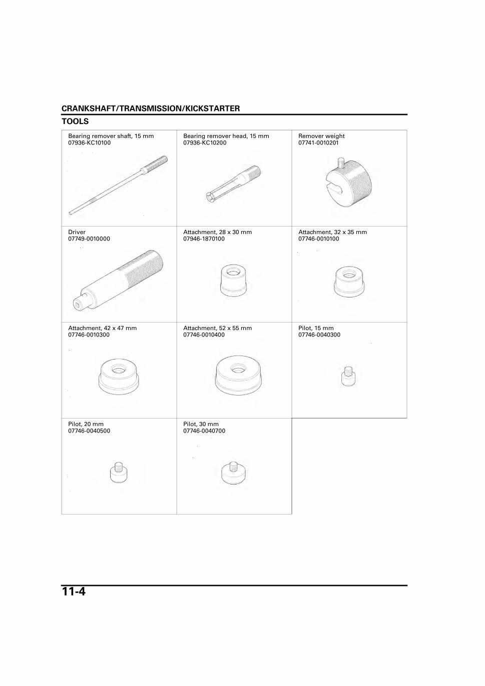
CRANKSHAFT/TRANSMISSION/KICKSTARTER
11-4
TOOLS
Bearing remover shaft, 15 mm07936-KC10100
Bearing remover head, 15 mm07936-KC10200
Remover weight07741-0010201
Driver07749-0010000
Attachment, 28 x 30 mm07946-1870100
Attachment, 32 x 35 mm07746-0010100
Attachment, 42 x 47 mm07746-0010300
Attachment, 52 x 55 mm07746-0010400
Pilot, 15 mm07746-0040300
Pilot, 20 mm07746-0040500
Pilot, 30 mm07746-0040700

CRANKSHAFT/TRANSMISSION/KICKSTARTER
11-5
TROUBLESHOOTINGHard to shift • Incorrect clutch adjustment • Damaged shift drum cam groove • Bent shift fork • Bent shift fork shaft
Transmission jumps out of gear • Worn gear engagement dogs or slots • Damaged or bent shift fork • Bent shift fork shaft • Damaged shift drum stopper arm • Broken shift linkage return spring • Damaged shift drum grooves
Excessive noise • Worn connecting rod big end bearing • Bent connecting rod • Worn crankshaft main journal bearing

CRANKSHAFT/TRANSMISSION/KICKSTARTER
11-6
CRANKCASE SEPARATIONRemove the following:
– Engine (page 6-6)– Footpeg bar (page 2-8)– Starter motor (page 17-6)– Cylinder head (page 7-12)– Cylinder (page 8-4)– Piston (page 8-10)– Oil pump (page 4-5)– Clutch (page 9-6)– Gearshift linkage (page 9-11)– Flywheel (page 10-6)– Primary drive gear (page 9-7)– Woodruff key (page 10-7)
Remove the push plug holder bolt and push plugholder.
Remove the clutch cable stay bolt and clutch cablestay.
Loosen the left crankcase bolts in crisscross patternin 2 or 3 steps and remove them.
Do not divide thecrankcase with a
screwdriver.
Place the right crankcase down; separate the leftand right crankcase into halves.
PUSH PLUG HOLDERPUSH PLUG HOLDER BOLT
CLUTCH CABLE STAY BOLT
LEFT CRANKCASE BOLTS
LEFT CRANKCASE
RIGHT CRANKCASE

CRANKSHAFT/TRANSMISSION/KICKSTARTER
11-7
Remove the gasket and dowel pins.
CRANKSHAFTRemove the crankshaft from the crankcase.
INSPECTIONMeasure the side clearance at the connecting rodbig end with a feeler gauge.
Measure the radial clearance of the connecting rodbig end.
GASKET
DOWEL PINS
CRANKSHAFT
SERVICE LIMIT: 0.5 mm (0.02 in)
FEELER GAUGE
SERVICE LIMIT: 0.05 mm (0.002 in)
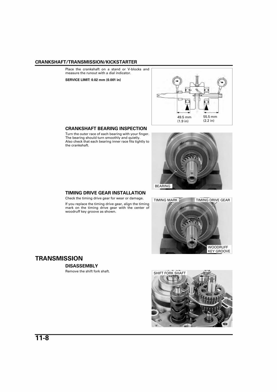
CRANKSHAFT/TRANSMISSION/KICKSTARTER
11-8
Place the crankshaft on a stand or V-blocks andmeasure the runout with a dial indicator.
CRANKSHAFT BEARING INSPECTIONTurn the outer race of each bearing with your finger.The bearing should turn smoothly and quietly.Also check that each bearing inner race fits tightly tothe crankshaft.
TIMING DRIVE GEAR INSTALLATIONCheck the timing drive gear for wear or damage.
If you replace the timing drive gear, align the timingmark on the timing drive gear with the center ofwoodruff key groove as shown.
TRANSMISSION
DISASSEMBLYRemove the shift fork shaft.
SERVICE LIMIT: 0.02 mm (0.001 in)
49.5 mm (1.9 in)
55.5 mm (2.2 in)
BEARING
TIMING DRIVE GEARTIMING MARK
WOODRUFF KEY GROOVE
SHIFT FORK SHAFT

CRANKSHAFT/TRANSMISSION/KICKSTARTER
11-9
Remove the shift drum.Remove the shift forks.
Remove the mainshaft and countershaft as anassembly from the crankcase.
Disassemble the mainshaft and countershaft.
INSPECTIONCheck the shift fork for wear, bending or damage.Measure the shift fork I.D.
Measure the shift fork claw thickness.
Check the shift fork shaft for bending wear or dam-age.Measure the shift fork shaft O.D.
SHIFT FORKS
SHIFT DRUM
MAINSHAFT COUNTERSHAFT
SERVICE LIMIT: 12.05 mm (0.474 in)
SERVICE LIMIT: 4.50 mm (0.177 in)
SHIFT FORK
SERVICE LIMIT: 11.96 mm (0.471 in)
SHIFT FORK SHAFT

CRANKSHAFT/TRANSMISSION/KICKSTARTER
11-10
Inspect the shift drum grooves.Replace the shift drum if the grooves are damagedor excessively worn.
TRANSMISSION INSPECTIONCheck the gear dogs, dog holes and teeth for abnor-mal wear or lack of lubrication.Measure the I.D. of each gear.
Measure the O.D. and I.D. of C1 gear bushing.
Measure the O.D. of both the mainshaft and thecountershaft.
TRANSMISSION BEARING REPLACE-MENTTurn the inner race of each bearing with your finger.The bearings should turn smoothly and quietly.Also check that the bearing outer race fits tightly inthe crankcase.
Remove and discard the bearings if the races do notturn smoothly, quietly, or if they fit loosely in thecrankcase.
SHIFT DRUM
SERVICE LIMITS:
M3, M5: 20.07 mm (0.790 in)
C1: 19.57 mm (0.770 in)
C2: 22.05 mm (0.868 in)
C4: 20.07 mm (0.790 in)
SERVICE LIMITS:
C1, O.D.: 19.43 mm (0.765 in)
C1, I.D.: 16.60 mm (0.654 in) GEAR BUSHINGGEAR
SERVICE LIMITS:
At M3 gear: 19.91 mm (0.784 in)
At C1 gear: 16.41 mm (0.646 in)
At C2 gear: 21.91 mm (0.863 in)
At C4 gear: 19.91 mm (0.784 in)
COUNTERSHAFT
M3
C4C2
MAINSHAFT
C1
BEARING

CRANKSHAFT/TRANSMISSION/KICKSTARTER
11-11
Remove the countershaft oil seal and gearshift spin-dle oil seal.
Remove the mainshaft bearing from the right crank-case.Remove the countershaft needle bearing from theright crankcase by using special tools.
Remove the countershaft bearing from the leftcrankcase.Remove the mainshaft bearing from the left crank-case by using special tools.
Apply engine oil to new bearings.Install the new bearing by using the following tools.
GEARSHIFT SPINDLE OIL SEAL
COUNTERSHAFT OIL SEAL
TOOLS:
Bearing remover shaft, 15 mm 07936-KC10100
Bearing remover head, 15 mm 07936-KC10200
Remover weight 07741-0010201
COUNTERSHAFT NEEDLE BEARING
WEIGHT
BEARING REMOVER
TOOLS:
Bearing remover shaft, 15 mm 07936-KC10100
Bearing remover head, 15 mm 07936-KC10200
Remover weight 07741-0010201
WEIGHT
BEARING REMOVER
MAINSHAFT BEARING
TOOLS:
Right crankcase mainshaft bearing:
Driver 07749-0010000
Attachment, 52 x 55 mm 07746-0010400
Pilot, 30 mm 07746-0040700
Right crankcase countershaft needle bearing:
Driver 07749-0010000
Attachment, 28 x 30 mm 07946-1870100
Pilot, 15 mm 07746-0040300
RIGHT CRANKCASE:
DRIVER
ATTACHMENT
PILOT MAINSHAFT BEARING

CRANKSHAFT/TRANSMISSION/KICKSTARTER
11-12
Apply engine oil to new bearings.Install the new bearing by using the following tools.
Apply engine oil to the new countershaft oil seal lipand new gearshift spindle oil seal lip, then installthem to the left crankcase.
ASSEMBLYMAINSHAFT:
TOOLS:
Left crankcase mainshaft bearing:
Driver 07749-0010000
Attachment, 32 x 35 mm 07746-0010100
Pilot, 15 mm 07746-0040300
Left crankcase countershaft bearing:
Driver 07749-0010000
Attachment, 42 x 47 mm 07746-0010300
Pilot, 20 mm 07746-0040500
LEFT CRANKCASE:
DRIVER
ATTACHMENT
PILOT COUNTERSHAFT BEARING
COUNTERSHAFT OIL SEAL
GEARSHIFT SPINDLE OIL SEAL
SPLINE WASHER
SNAP RING
THRUST WASHER
STARTER DRIVE GEAR (19T)MAINSHAFT/M1 GEAR (12T)
M3 GEAR (20T)
M4 GEAR (23T)
M5 GEAR (25T)
M2 GEAR (17T)SNAP RING
SPLINE WASHER
M5 GEAR (25T)
THRUST WASHER
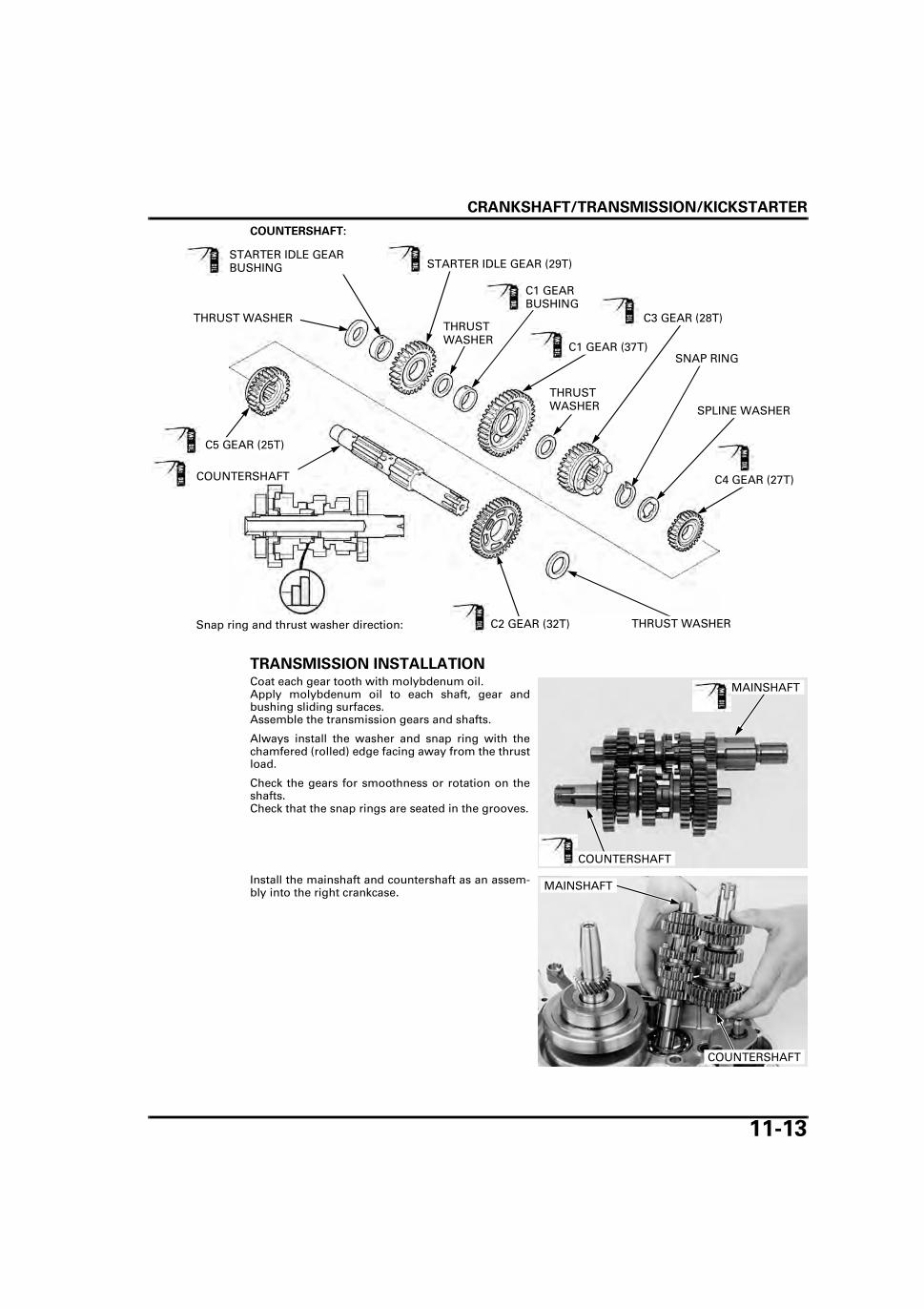
CRANKSHAFT/TRANSMISSION/KICKSTARTER
11-13
COUNTERSHAFT:
TRANSMISSION INSTALLATIONCoat each gear tooth with molybdenum oil.Apply molybdenum oil to each shaft, gear andbushing sliding surfaces.Assemble the transmission gears and shafts.
Always install the washer and snap ring with thechamfered (rolled) edge facing away from the thrustload.
Check the gears for smoothness or rotation on theshafts.Check that the snap rings are seated in the grooves.
Install the mainshaft and countershaft as an assem-bly into the right crankcase.
C5 GEAR (25T)
C4 GEAR (27T)
C1 GEAR (37T)
C3 GEAR (28T)
C2 GEAR (32T)
COUNTERSHAFT
THRUST WASHER
SNAP RING
SPLINE WASHER
THRUST WASHER
THRUST WASHER
C1 GEAR BUSHING
STARTER IDLE GEAR (29T)STARTER IDLE GEAR BUSHING
THRUST WASHER
Snap ring and thrust washer direction:
MAINSHAFT
COUNTERSHAFT
MAINSHAFT
COUNTERSHAFT

CRANKSHAFT/TRANSMISSION/KICKSTARTER
11-14
Each shift fork has an identification mark; "R" is forthe right shift fork, "C" is for the center shift fork,and "L" is for the left shift fork.
Apply engine oil to the shift forks sliding surfaces.Install the right shift fork into the C5 shifter groovewith its mark facing the right crankcase.Install the center shift fork into the M4 shiftergroove with its mark facing the left crankcase.Install the left shift fork into the C3 shifter groovewith its mark facing the right crankcase.Install the shift drum.
Apply engine oil to the shift fork shaft and install it.
After installation, check for smooth transmissionoperation.
KICKSTARTER
REMOVALUnhook the ratchet guide plate and starter ratchetand remove the kickstarter assembly.
"L" MARK "C" MARK "R" MARK
LEFT SHIFT FORK
CENTER SHIFT FORK
SHIFT DRUM
RIGHT SHIFT FORK
SHIFT FORK SHAFT
GUIDE PLATE
STARTER RATCHET

CRANKSHAFT/TRANSMISSION/KICKSTARTER
11-15
DISASSEMBLYRemove the following:
– Thrust washer, 16 mm– Spindle collar– Kickstarter spring– Spring retainer
Remove the following:
– Thrust washer, 12 mm– Snap ring, 16 mm– Ratchet guide plate– Ratchet spring– Thrust washer, 16 mm
Remove the starter ratchet.
Remove the following:
– Snap ring, 20 mm– Thrust washer, 20 mm– Kickstarter pinion gear
RETAINER
COLLAR
WASHER
SPRING
WASHER RATCHET GUIDE PLATE
WASHER
SNAP RINGSPRING
STARTER RATCHET
PINION GEARSNAP RING
THRUST WASHER

CRANKSHAFT/TRANSMISSION/KICKSTARTER
11-16
INSPECTIONMeasure the kickstarter pinion I.D.
Measure the O.D. of the kickstarter pinion gear slid-ing surface on the spindle.
ASSEMBLY
Apply molybdenum oil to the kickstarter pinion gearteeth and inner surface.
Install the following:
– Kickstarter pinion gear– Thrust washer, 20 mm– Snap ring, 20 mm
SERVICE LIMIT: 20.05 mm (0.789 in)
SERVICE LIMIT: 19.90 mm (0.783 in)
SPINDLE COLLAR
KICKSTARTER SPRING
STARTER RATCHET
PINION GEAR
RATCHET GUIDE PLATE
RATCHET SPRING
SPINDLE
SPRING RETAINER
Snap ring and thrust washer direction:
PINION GEARSNAP RING
THRUST WASHER

CRANKSHAFT/TRANSMISSION/KICKSTARTER
11-17
Install the starter ratchet by aligning the punchmarks on the starter ratchet and spindle.
Install the following:
– Thrust washer, 16 mm– Ratchet spring– Ratchet guide plate– Snap ring, 16 mm– Thrust washer, 12 mm
Install the following:
– Spring retainer– Kickstarter spring– Spindle collar
Install the kickstarter spring end into the spindle.
STARTER RATCHET MARKS
WASHER RATCHET GUIDE PLATE
WASHER
SNAP RINGSPRING
RETAINER
COLLAR
SPRING
SPRING ENDCOLLAR

CRANKSHAFT/TRANSMISSION/KICKSTARTER
11-18
Align the cut-out of the spindle collar with thespring end.
Install the thrust washer.
INSTALLATIONApply engine oil to the kickstarter assembly.
Install the kickstarter assembly into the left crank-case.
Hook the kickstarter spring end to the left crankcasehole.
Hold the kickstarter spindle and hook the starterratchet and ratchet guide plate to the left crankcase.
SPRING ENDCOLLAR
WASHER
KICKSTARTER ASSEMBLY
GUIDE PLATE
STARTER RATCHET
Hook
Hook

CRANKSHAFT/TRANSMISSION/KICKSTARTER
11-19
CRANKCASE ASSEMBLYApply oil to the crankshaft bearing.Install the crankshaft into the right crankcase.
Install the dowel pins and new gasket.
Make sure that thegasket stays in
place during thisoperation.
Install the left crankcase on the right crankcase.
Install the left crankcase bolts and tighten themsecurely in a crisscross pattern in 2-3 steps.
CRANKSHAFT BEARING
GASKET
DOWEL PINS
LEFT CRANKCASE
RIGHT CRANKCASE
LEFT CRANKCASE BOLTS

CRANKSHAFT/TRANSMISSION/KICKSTARTER
11-20
Install the clutch cable stay and tighten the clutchcable stay bolt.
Check the push plug, spring, and push plug holderfor wear or damage and replace them with newones if necessary.
Apply clean engine oil to the spring.Apply clean engine oil to the push plug surface andspring end.
Apply clean engine oil to the new O-ring and installit to the push plug holder.Install the push plug holder assembly to the leftcrankcase.Install and tighten the push plug holder bolt to thespecified torque.
Install the following:
– Woodruff key (page 10-9)– Primary drive gear (page 9-9)– Flywheel (page 10-9)– Gearshift linkage (page 9-12)– Clutch (page 9-9)– Oil pump (page 4-9)– Piston (page 8-12)– Cylinder (page 8-5)– Cylinder head (page 7-20)– Starter motor (page 17-13)– Footpeg bar (page 2-8)– Engine (page 6-10)
CLUTCH CABLE STAY BOLT
PUSH PLUG
PUSH PLUG HOLDERSPRING
TORQUE: 13 N·m (1.3 kgf·m, 10 lbf·ft)
PUSH PLUG HOLDER ASSEMBLY
PUSH PLUG HOLDER BOLTO-RING

12-1
12
12. FRONT WHEEL/BRAKE/SUSPENSION/STEERING
SYSTEM COMPONENTS ···························· 12-2
SERVICE INFORMATION ···························· 12-4
TROUBLESHOOTING ·································· 12-6
HANDLEBAR ················································ 12-7
FRONT WHEEL (TYPE: I, III) ······················ 12-11
FRONT WHEEL (TYPE: II, IV) ·····················12-15
FRONT DRUM BRAKE (TYPE: I, III) ···········12-20
FORK ···························································12-24
STEERING STEM········································12-31

FRONT WHEEL/BRAKE/SUSPENSION/STEERING
12-2
FRONT WHEEL/BRAKE/SUSPENSION/STEERING
SYSTEM COMPONENTS
TYPE I, III
52 N·m (5.3 kgf·m, 38 lbf·ft)
12 N·m (1.2 kgf·m, 9 lbf·ft)
74 N·m (7.5 kgf·m, 55 lbf·ft)
34 N·m (3.5 kgf·m, 25 lbf·ft)

FRONT WHEEL/BRAKE/SUSPENSION/STEERING
12-3
TYPE II, IV
52 N·m (5.3 kgf·m, 38 lbf·ft)
12 N·m (1.2 kgf·m, 9 lbf·ft)
74 N·m (7.5 kgf·m, 55 lbf·ft)
34 N·m (3.5 kgf·m, 25 lbf·ft)

FRONT WHEEL/BRAKE/SUSPENSION/STEERING
12-4
SERVICE INFORMATION
GENERAL
• When servicing the front wheel, fork or steering stem, support the motorcycle using a safety stand or hoist. • A contaminated brake disc or pad reduces stopping power. Discard contaminated pads and clean a contaminated disc
with a high quality brake degreasing agent. • After the front wheel installation, check the brake operation by applying the brake lever. • Refer to hydraulic brake system information (page 14-3).
SPECIFICATIONSUnit: mm (in)
TORQUE VALUES
Frequent inhalation of brake shoe dust, regardless of material composition could be hazardous to your health. • Avoid breathing dust particles. • Never use an air hose or brush to clean brake assemblies. Use an OSHA-approved vacuum cleaner.
ITEM STANDARD SERVICE LIMIT
Minimum tire thread depth – To wear indicatorCold tire pres-sure
Driver only 200 kPa (2.00 kgf/cm2, 29 psi) –Driver and passenger 200 kPa (2.00 kgf/cm2, 29 psi) –
Axle runout – 0.2 (0.01)Wheel rim runout
Radial – 1.0 (0.04)Axial – 1.0 (0.04)
Drum brake (Type I, III)
Lever free play 10 – 20 (0.4 – 0.8) –Drum I.D. 130.0 – 130.3 (5.12 – 5.13) 131.0 (5.16)
Fork Spring free length 485.5 (19.11) 457.2 (18.0)Pipe runout – 0.20 (0.008)Recommended fluid Fork fluid –Fluid level 159 (6.26) –Fluid capacity 65.0 cm3 (2.20 US oz, 2.29 lmp oz) –
Steering head bearing pre-load 1.6 – 2.4 kgf (3.53 – 5.29 lbf) –
Handlebar holder bolt 12 N·m (1.2 kgf·m, 9 lbf·ft) Front brake disc bolt (Type II, IV) 42 N·m (4.3 kgf·m, 31 lbf·ft) ALOC bolt; replace with a new one.Front axle nut 52 N·m (5.3 kgf·m, 38 lbf·ft)Front brake arm nut (Type I, III) 10 N·m (1.0 kgf·m, 7 lbf·ft) U-nutFork cap 22 N·m (2.2 kgf·m, 16 lbf·ft)Top bridge pinch bolt 23 N·m (2.3 kgf·m, 17 lbf·ft)Bottom bridge pinch bolt 34 N·m (3.5 kgf·m, 25 lbf·ft)Steering bearing adjustment nut See page 12-35Steering stem nut 74 N·m (7.5 kgf·m, 55 lbf·ft)
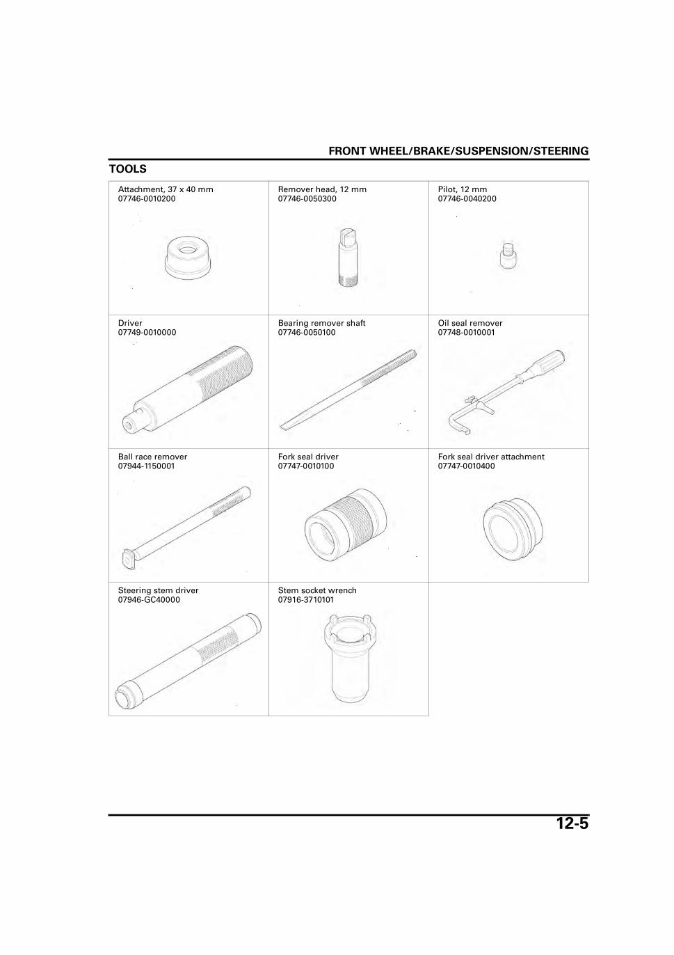
FRONT WHEEL/BRAKE/SUSPENSION/STEERING
12-5
TOOLS
Attachment, 37 x 40 mm07746-0010200
Remover head, 12 mm07746-0050300
Pilot, 12 mm07746-0040200
Driver07749-0010000
Bearing remover shaft07746-0050100
Oil seal remover07748-0010001
Ball race remover07944-1150001
Fork seal driver07747-0010100
Fork seal driver attachment07747-0010400
Steering stem driver07946-GC40000
Stem socket wrench07916-3710101

FRONT WHEEL/BRAKE/SUSPENSION/STEERING
12-6
TROUBLESHOOTINGHard steering • Steering stem adjusting nut too tight • Damaged steering head bearing/race • Insufficient tire pressure • Faulty tire
Steers to one side or does not track straight • Bent fork • Bent front axle • Wheel installed incorrectly • Faulty steering head bearing • Bent frame • Faulty wheel bearing • Worn swingarm pivot components • Weak front fork
Front wheel wobbling • Bent rim • Worm wheel bearings • Faulty tire
Wheel hard to turn • Faulty wheel bearing • Faulty speedometer gear • Bent front axle • Brake drag
Soft suspension • Weak front fork spring • Insufficient fork fluid • Tire pressure too low
Hard suspension • Incorrect fork fluid viscosity • Bent fork pipes • Clogged fluid passage • Damaged fork pipe and/or fork slider
Front suspension noisy • Insufficient fluid in fork • Loose front fork fasteners • Lack of grease in speedometer gear

FRONT WHEEL/BRAKE/SUSPENSION/STEERING
12-7
HANDLEBARREMOVALRemove the wire bands and rear view mirrors.
When removing theweight, do not
remove the screwfrom the nut.
Hold the handlebar weight and loosen the screw.
Remove the handlebar weight, rubber and nutassembly.
Disconnect the front brake light switch connectors.
Remove the bolts and brake lever bracket holder.
Remove the master cylinder.
Remove the brake lever bracket.
Remove the right handlebar switch housing screws.
REAR VIEW MIRRORS
WIRE BANDS
SCREW
HANDLEBAR WEIGHT
RUBBER
NUT SCREW
Type II and IV:
Type I and III:
BOLTS
HOLDER
CONNECTORS
MASTER CYLINDER
DISC BRAKE TYPE shown:
SCREWS
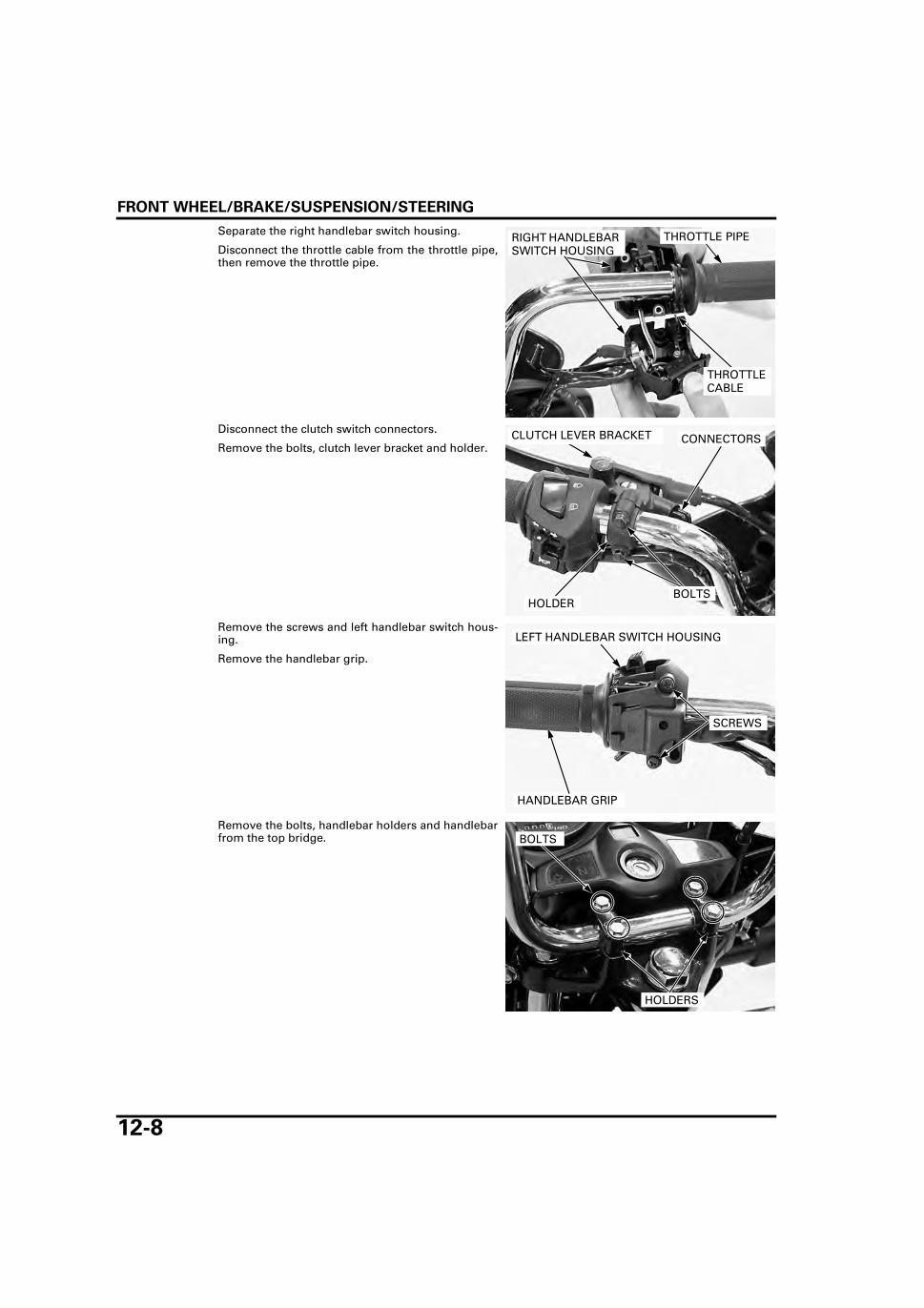
FRONT WHEEL/BRAKE/SUSPENSION/STEERING
12-8
Separate the right handlebar switch housing.
Disconnect the throttle cable from the throttle pipe,then remove the throttle pipe.
Disconnect the clutch switch connectors.
Remove the bolts, clutch lever bracket and holder.
Remove the screws and left handlebar switch hous-ing.
Remove the handlebar grip.
Remove the bolts, handlebar holders and handlebarfrom the top bridge.
THROTTLE PIPE
THROTTLE CABLE
RIGHT HANDLEBAR SWITCH HOUSING
CONNECTORS
BOLTS
CLUTCH LEVER BRACKET
HOLDER
HANDLEBAR GRIP
SCREWS
LEFT HANDLEBAR SWITCH HOUSING
BOLTS
HOLDERS
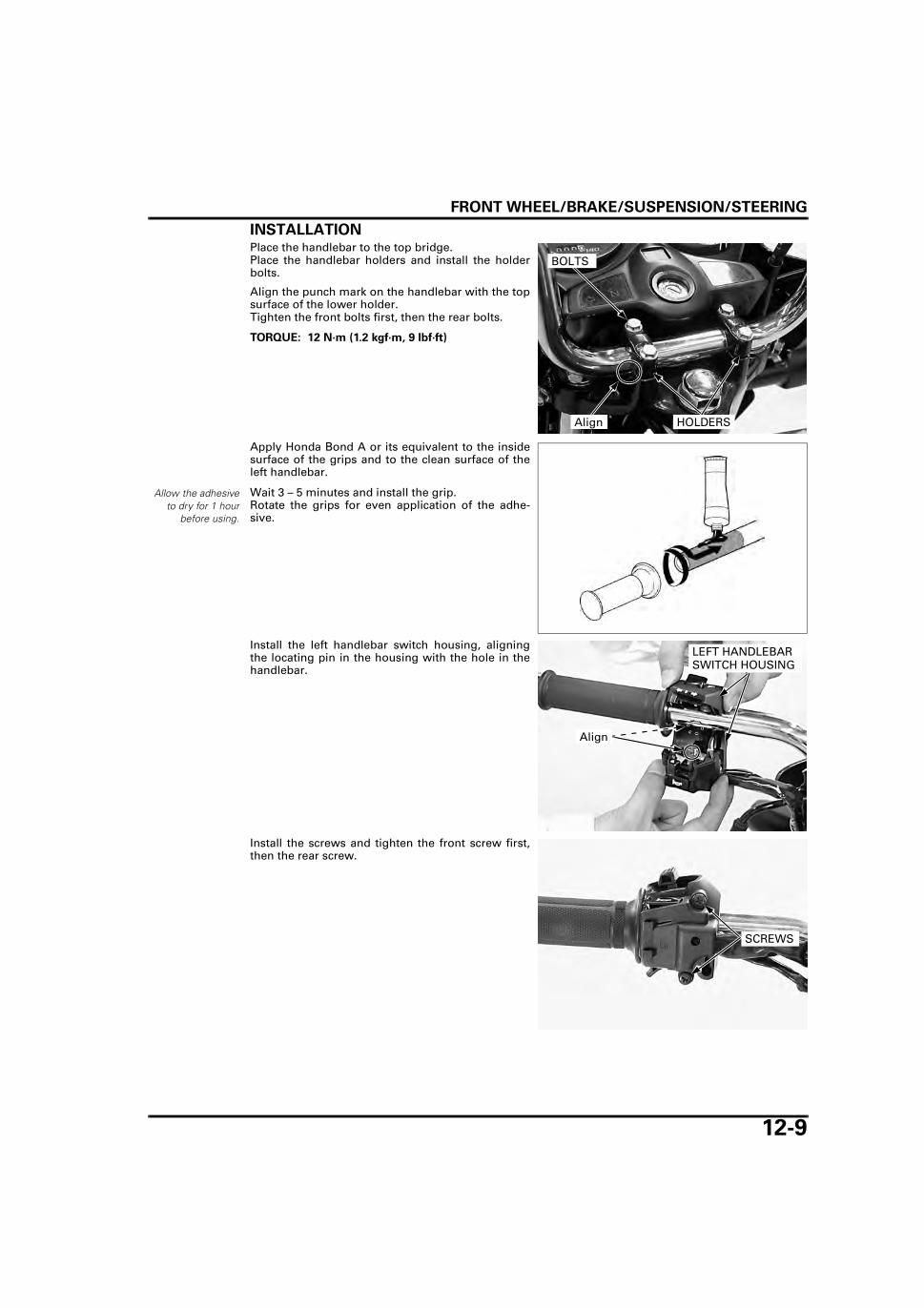
FRONT WHEEL/BRAKE/SUSPENSION/STEERING
12-9
INSTALLATIONPlace the handlebar to the top bridge.Place the handlebar holders and install the holderbolts.
Align the punch mark on the handlebar with the topsurface of the lower holder.Tighten the front bolts first, then the rear bolts.
Apply Honda Bond A or its equivalent to the insidesurface of the grips and to the clean surface of theleft handlebar.
Wait 3 – 5 minutes and install the grip.Rotate the grips for even application of the adhe-sive.
Install the left handlebar switch housing, aligningthe locating pin in the housing with the hole in thehandlebar.
Install the screws and tighten the front screw first,then the rear screw.
TORQUE: 12 N·m (1.2 kgf·m, 9 lbf·ft)
BOLTS
HOLDERSAlign
Allow the adhesiveto dry for 1 hour
before using.
Align
LEFT HANDLEBAR SWITCH HOUSING
SCREWS

FRONT WHEEL/BRAKE/SUSPENSION/STEERING
12-10
Install the clutch lever bracket onto the left side ofhandlebar aligning the end of bracket with thepunch mark on the handlebar.
Install the holder with the “UP” mark facing up.Install the bolts and tighten the upper bolt first, thentighten the lower bolt.
Connect the clutch switch connectors.
Install the throttle pipe on the handlebar.Apply grease to the throttle cable contacting area ofthe throttle pipe and throttle cable end.Connect the throttle cable end to the throttle pipe.
Install the right handlebar switch housing, aligningits locating pin with the hole on the handlebar.
Install the screws and tighten the front screw first,then the rear screw.
Type II and IV: Install the master cylinder aligning the end ofbracket with the punch mark on the handlebar.
Install the brake lever bracket aligning the end ofbracket with the punch mark on the handlebar.
Install the holder with the “UP” mark facing up.Install the bolts and tighten the upper bolt first, thentighten the lower bolt.
Connect the brake light switch connectors.
Align "UP" MARKBOLT
HOLDERBRACKET CONNECTORS
THROTTLE PIPE
THROTTLE CABLE
RIGHT HANDLEBAR SWITCH HOUSING
Align
SCREWS
Type I and III:
Align
"UP" MARK
BOLTHOLDERBRACKET
CONNECTORS

FRONT WHEEL/BRAKE/SUSPENSION/STEERING
12-11
Temporarily assemble the handlebar weight, rubberand nut.
Install the handlebar weight assembly to the han-dlebar.
Hold the handlebar weight and tighten the screwuntil the handlebar weight is tight.
Route the wire har-ness properly (typeI and III: page 1-18,type II and IV:page
1-19).
Install the wire bands and rear view mirrors.
Check the throttle grip free play (page 3-5).
Adjust the clutch lever free play (page 3-18).
FRONT WHEEL (TYPE: I, III)
REMOVALRaise and support the motorcycle using safetystand or a box.
Remove the retaining clip and disconnect thespeedometer cable.
Remove the front brake adjusting nut, brake cableand brake arm joint pin.
Remove the axle nut.Remove the axle and front wheel.
Remove the side collar and dust seal.
SCREW
HANDLEBAR WEIGHT
RUBBER
NUT
REAR VIEW MIRRORS
WIRE BANDS
RETAINING CLIPADJUSTING NUT
BRAKE CABLE
JOINT PIN
SPEEDOMETER CABLEAXLE/NUT
SIDE COLLAR DUST SEAL
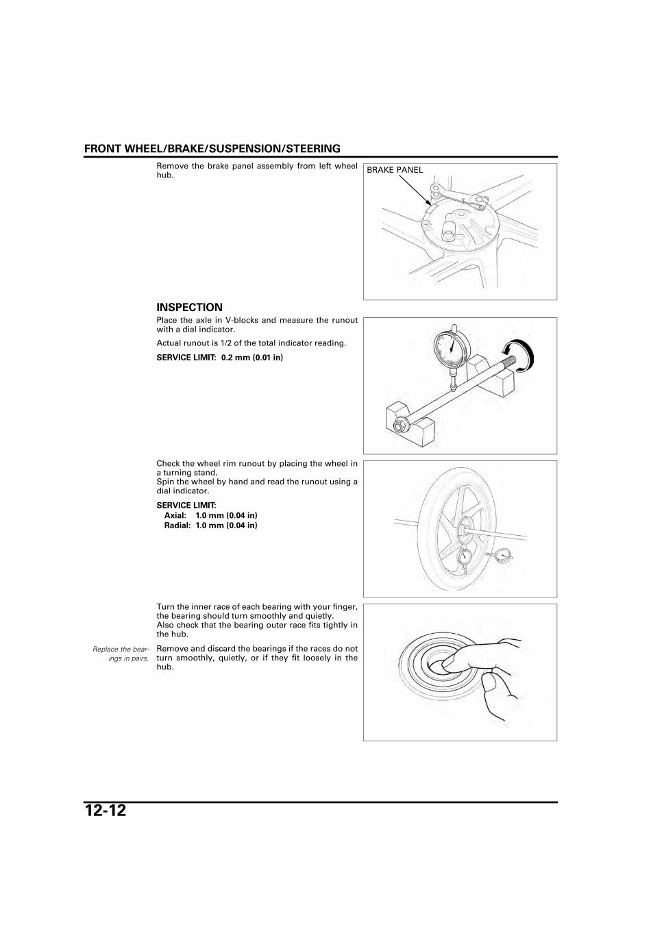
FRONT WHEEL/BRAKE/SUSPENSION/STEERING
12-12
Remove the brake panel assembly from left wheelhub.
INSPECTIONPlace the axle in V-blocks and measure the runoutwith a dial indicator.
Actual runout is 1/2 of the total indicator reading.
Check the wheel rim runout by placing the wheel ina turning stand.Spin the wheel by hand and read the runout using adial indicator.
Turn the inner race of each bearing with your finger,the bearing should turn smoothly and quietly.Also check that the bearing outer race fits tightly inthe hub.
Remove and discard the bearings if the races do notturn smoothly, quietly, or if they fit loosely in thehub.
BRAKE PANEL
SERVICE LIMIT: 0.2 mm (0.01 in)
SERVICE LIMIT:
Axial: 1.0 mm (0.04 in)
Radial: 1.0 mm (0.04 in)
Replace the bear-ings in pairs.

FRONT WHEEL/BRAKE/SUSPENSION/STEERING
12-13
DISASSEMBLYInstall the bearing remover head into the bearing.From the opposite side, install the bearing removershaft and drive the bearing out of the wheel hub.Remove the distance collar and drive out the otherbearing.
ASSEMBLY
WHEEL ASSEMBLY
Never install the oldbearing, once thebearing has been
removed, the bear-ing must be
replaced with newones.
Pack all bearing cavities with grease.Drive in a new left (brake drum side) bearingsquarely with its sealed side facing up until it is fullyseated.Install the distance collar.Drive in a new right bearing squarely with its sealedside facing up.
TOOLS:
Remover head, 12 mm 07746-0050300
Bearing remover shaft 07746-0050100
REMOVER HEAD
REMOVER SHAFTBEARING
DUST SEAL
RIGHT WHEEL BEARING (6301U)
DISTANCE COLLAR
LEFT WHEEL BEARING (6301U)
TOOLS:
Driver 07749-0010000
Attachment, 37 x 40 mm 07746-0010200
Pilot, 12 mm 07746-0040200
DRIVER
ATTACHMENT
DISTANCE COLLAR
Fully seated
PILOTBEARINGS
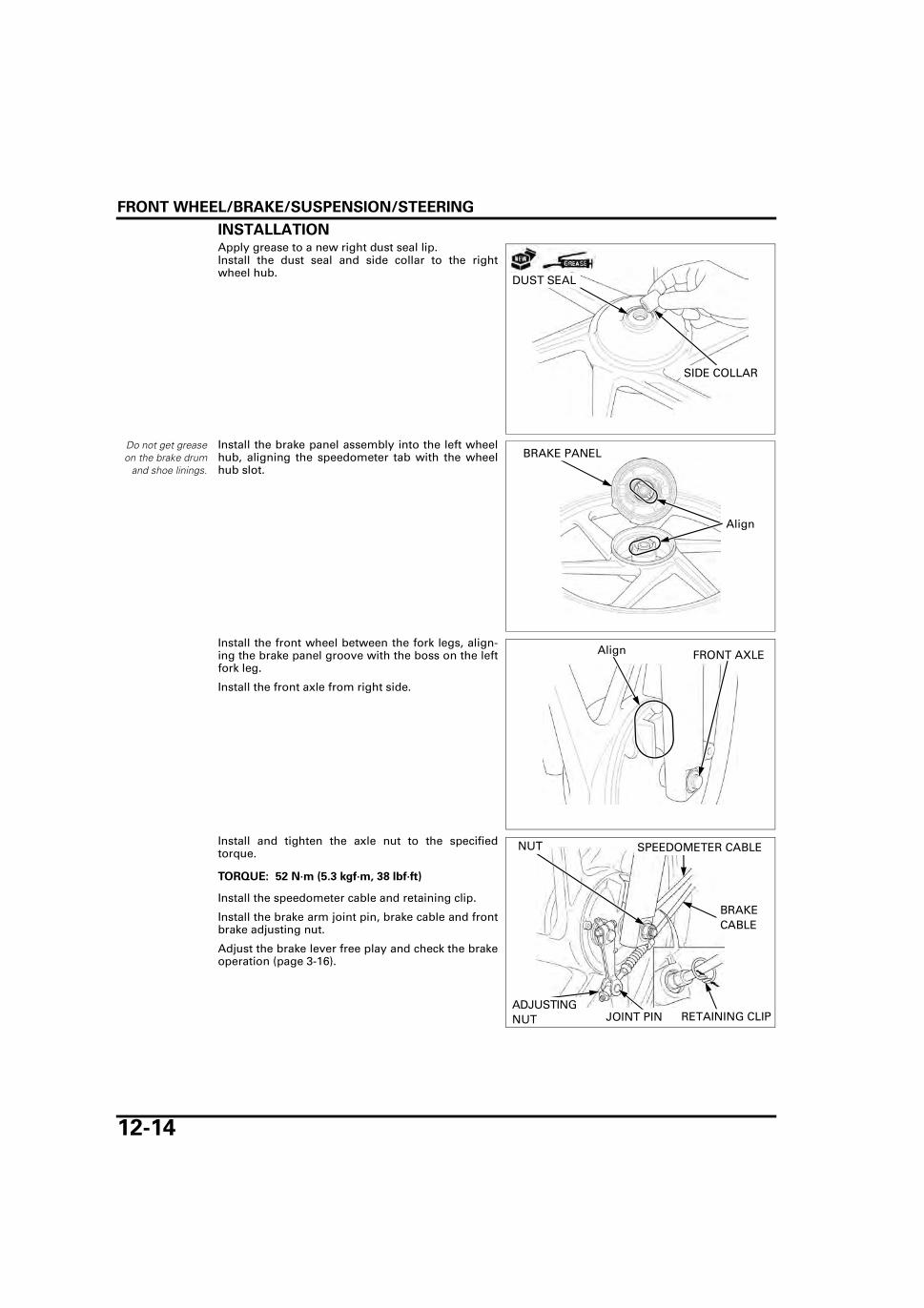
FRONT WHEEL/BRAKE/SUSPENSION/STEERING
12-14
INSTALLATIONApply grease to a new right dust seal lip.Install the dust seal and side collar to the rightwheel hub.
Do not get greaseon the brake drum
and shoe linings.
Install the brake panel assembly into the left wheelhub, aligning the speedometer tab with the wheelhub slot.
Install the front wheel between the fork legs, align-ing the brake panel groove with the boss on the leftfork leg.
Install the front axle from right side.
Install and tighten the axle nut to the specifiedtorque.
Install the speedometer cable and retaining clip.
Install the brake arm joint pin, brake cable and frontbrake adjusting nut.
Adjust the brake lever free play and check the brakeoperation (page 3-16).
DUST SEAL
SIDE COLLAR
BRAKE PANEL
Align
Align FRONT AXLE
TORQUE: 52 N·m (5.3 kgf·m, 38 lbf·ft)
RETAINING CLIPADJUSTING NUT
BRAKE CABLE
JOINT PIN
SPEEDOMETER CABLENUT
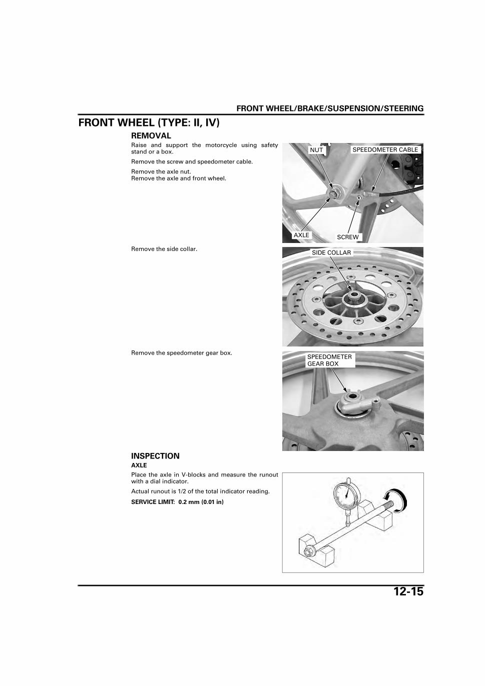
FRONT WHEEL/BRAKE/SUSPENSION/STEERING
12-15
FRONT WHEEL (TYPE: II, IV)
REMOVALRaise and support the motorcycle using safetystand or a box.
Remove the screw and speedometer cable.
Remove the axle nut.Remove the axle and front wheel.
Remove the side collar.
Remove the speedometer gear box.
INSPECTIONAXLE
Place the axle in V-blocks and measure the runoutwith a dial indicator.
Actual runout is 1/2 of the total indicator reading.
SPEEDOMETER CABLENUT
SCREWAXLE
SIDE COLLAR
SPEEDOMETER GEAR BOX
SERVICE LIMIT: 0.2 mm (0.01 in)

FRONT WHEEL/BRAKE/SUSPENSION/STEERING
12-16
WHEEL RIM RUNOUT
Check the wheel rim runout by placing the wheel ina turning stand.Spin the wheel by hand and read the runout using adial indicator.
WHEEL BEARING
Turn the inner race of each bearing with your finger,the bearing should turn smoothly and quietly.Also check that the bearing outer race fits tightly inthe hub.
Remove and discard the bearings if the races do notturn smoothly, quietly, or if they fit loosely in thehub.
DISASSEMBLYRemove the left dust seal from the left side of thefront wheel.
Remove the speedometer gear retainer.
SERVICE LIMIT:
Axial: 1.0 mm (0.04 in)
Radial: 1.0 mm (0.04 in)
Replace the bear-ings in pairs.
DUST SEAL
RETAINER
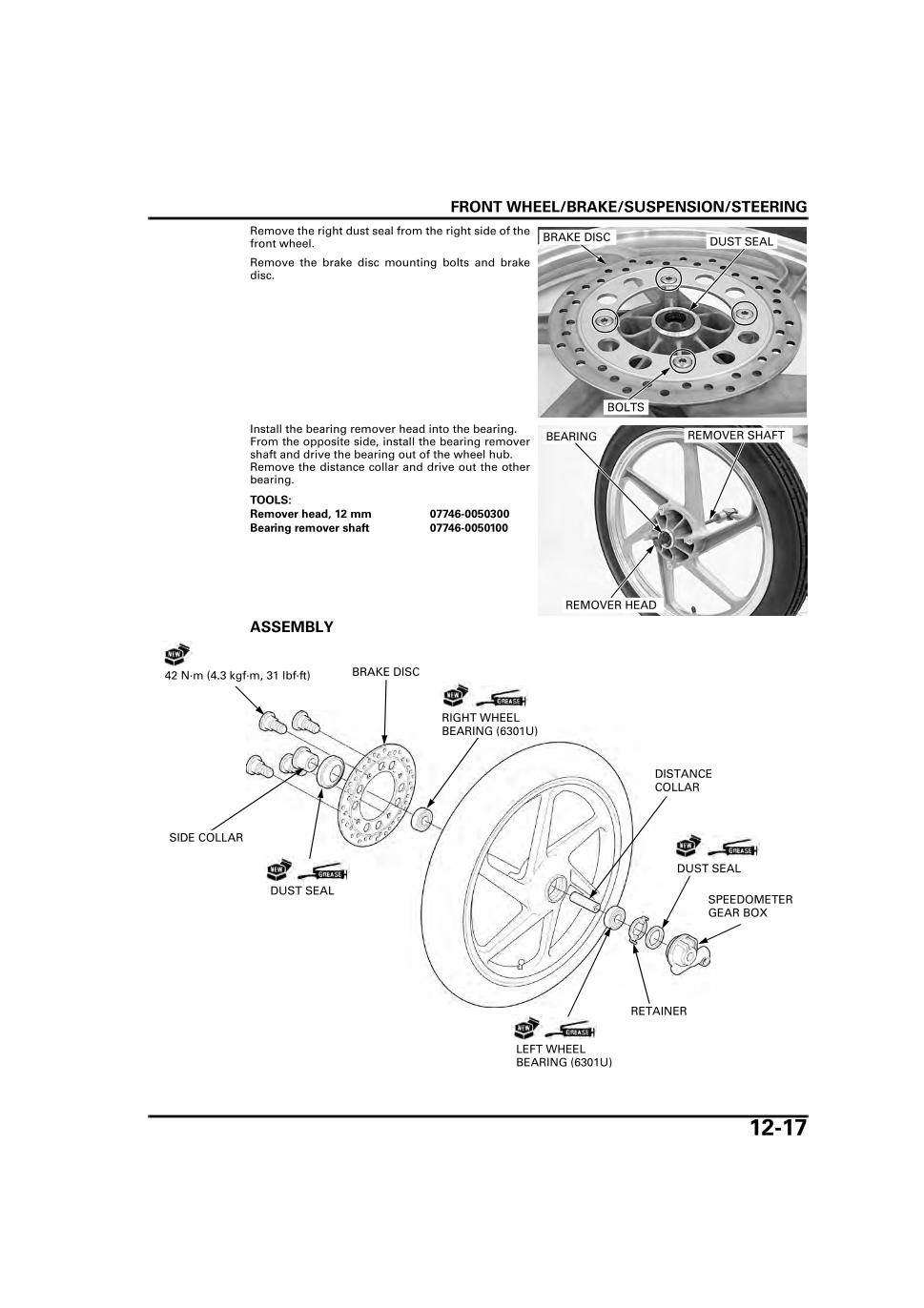
FRONT WHEEL/BRAKE/SUSPENSION/STEERING
12-17
Remove the right dust seal from the right side of thefront wheel.
Remove the brake disc mounting bolts and brakedisc.
Install the bearing remover head into the bearing.From the opposite side, install the bearing removershaft and drive the bearing out of the wheel hub.Remove the distance collar and drive out the otherbearing.
ASSEMBLY
BOLTS
BRAKE DISC DUST SEAL
TOOLS:
Remover head, 12 mm 07746-0050300
Bearing remover shaft 07746-0050100
REMOVER HEAD
REMOVER SHAFTBEARING
DUST SEAL
LEFT WHEEL BEARING (6301U)
DISTANCE COLLAR
SPEEDOMETER GEAR BOX
DUST SEAL
BRAKE DISC42 N·m (4.3 kgf·m, 31 lbf·ft)
RIGHT WHEEL BEARING (6301U)
SIDE COLLAR
RETAINER

FRONT WHEEL/BRAKE/SUSPENSION/STEERING
12-18
WHEEL ASSEMBLY
Never install the oldbearing, once thebearing has been
removed, the bear-ing must be
replaced with newones.
Pack all bearing cavities with grease.Drive in a new right (brake disc side) bearingsquarely with its sealed side facing up until it is fullyseated.Install the distance collar.Drive in a new left bearing squarely with its sealedside facing up.
Do not get greaseon the brake disc orstopping power will
be reduced.
Install and tighten the new brake disc bolts in acrisscross pattern in 2 or 3 steps.
Apply grease to a new right dust seal lip.Install the dust seal to the right wheel hub.
Install the speedometer gear retainer to the wheelhub, aligning the tabs on the retainer with the slotson the hub.
Apply grease to a new left dust seal lip.Install the dust seal to the left wheel hub.
TOOLS:
Driver 07749-0010000
Attachment, 37 x 40 mm 07746-0010200
Pilot, 12 mm 07746-0040200
DRIVER
ATTACHMENT PILOT
DISTANCE COLLAR
Fully seated
BEARINGS
TORQUE: 42 N·m (4.3 kgf·m, 31 lbf·ft)
BOLTS
BRAKE DISC DUST SEAL
RETAINER
Align
DUST SEAL

FRONT WHEEL/BRAKE/SUSPENSION/STEERING
12-19
INSTALLATIONInstall the speedometer gear box into the left wheelhub, aligning the tabs with the slots.
Install the side collar into the right wheel hub.
Be careful not todamage the pads.
Install the front wheel between the fork legs, align-ing the speedometer gear box groove with the bosson the fork leg so that the brake disc is positionedbetween the pads.
Insert the front axle from the right fork leg.
Install and tighten the axle nut to the specifiedtorque.
Install the speedometer cable to the speedometergear box aligning slot of the cable and the tab of thegear box.
Install and tighten the screw.
SPEEDOMETER GEAR BOX
Align
SIDE COLLAR
TORQUE: 52 N·m (5.3 kgf·m, 38 lbf·ft)
FRONT AXLE
AlignAXLE NUT
SPEEDOMETER CABLE
SCREWAlign

FRONT WHEEL/BRAKE/SUSPENSION/STEERING
12-20
FRONT DRUM BRAKE (TYPE: I, III)
INSPECTIONRemove the front wheel (page 12-11).
Measure the front brake drum I.D.
DISASSEMBLYRemove the brake panel assembly (page 12-12).
Expand the brake shoes and remove them from thebrake panel.
Remove the shoe springs from the brake shoes.
Remove the following:
– Nut and bolt– Return spring (from the brake arm)– Brake arm
Remove the wear indicator.
SERVICE LIMIT: 131.0 mm (5.16 in)
Always replace thebrake shoes in
pairs.
BRAKE SHOES
SPRINGS
BOLTBRAKE ARM
RETURN SPRING
NUT
WEAR INDICATOR

FRONT WHEEL/BRAKE/SUSPENSION/STEERING
12-21
Remove the following:
– Return spring– Felt seal
Remove the brake cam.
Remove the following:
– Dust seal– Snap ring– Washer
Remove the following:
– Speedometer gear– Washer
RETURN SPRING
FELT SEAL
BRAKE CAM
SNAP RING
WASHERDUST SEAL
SPEEDOMETER GEAR
WASHER

FRONT WHEEL/BRAKE/SUSPENSION/STEERING
12-22
ASSEMBLY
Apply grease to the speedometer gear.Install the washer and speedometer gear.
Install the washer and snap ring.
Apply grease to a new dust seal lip.Install the dust seal to the brake panel.
SHOE SPRING
BRAKE CAM
BRAKE ARM
DRUM BRAKE PANEL
DUST SEAL
FELT SEAL
RETURN SPRING BRAKE SHOE
SPEEDOMETER GEAR
WEAR INDICATOR
10 N·m (1.0 kgf·m, 7 lbf·ft)
WASHER
SNAP RING GEAR OIL
SPEEDOMETER GEAR
WASHER
SNAP RING
WASHER
DUST SEAL
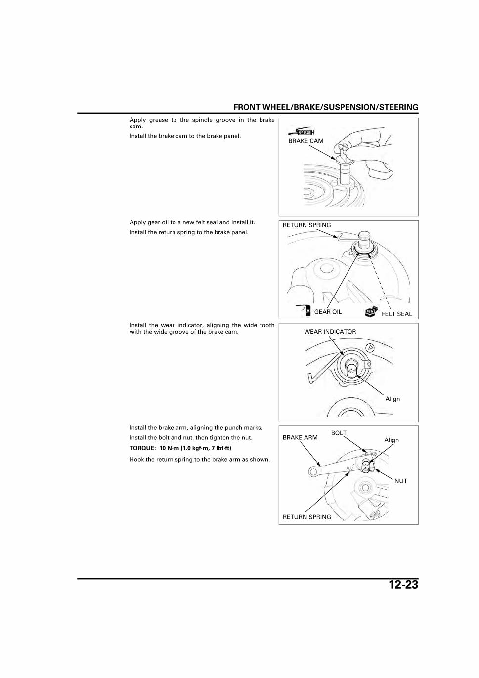
FRONT WHEEL/BRAKE/SUSPENSION/STEERING
12-23
Apply grease to the spindle groove in the brakecam.
Install the brake cam to the brake panel.
Apply gear oil to a new felt seal and install it.
Install the return spring to the brake panel.
Install the wear indicator, aligning the wide toothwith the wide groove of the brake cam.
Install the brake arm, aligning the punch marks.
Install the bolt and nut, then tighten the nut.
Hook the return spring to the brake arm as shown.
BRAKE CAM
RETURN SPRING
FELT SEALGEAR OIL
WEAR INDICATOR
Align
TORQUE: 10 N·m (1.0 kgf·m, 7 lbf·ft)
BOLTBRAKE ARM
RETURN SPRING
NUT
Align

FRONT WHEEL/BRAKE/SUSPENSION/STEERING
12-24
Apply grease to the anchor pin and brake cam slid-ing surfaces.
Assemble the brake shoes and springs as shown.Install the shoe assembly onto the brake panel.
Wipe any excess grease from the brake cam andanchor pin.
Install the brake panel assembly (page 12-14).
FORK
REMOVALType II and IV: sup-
port the caliper so itdoes not hang fromthe brake hose. Donot twist the brake
hose.
Remove the brake caliper (page 14-15).
Remove the following:– Front cowl (page 2-7)– Front wheel (type II and IV: page 12-15 or type I
and III: page 12-11)– Front fender (page 2-6)– License plate holder (page 2-8)– Combination meter unit (page 18-6)
Loosen the front cowl bracket bolts and slightly pullup the bracket.Loosen the fork top pinch bolts.
If the fork will bedisassembled,
loosen the fork capwhen bottom pinch
bolts fastenedwhile having
removed forkdownward.
Loosen the fork bottom pinch bolts and pull out thefork pipe.
DISASSEMBLYRemove the fork cap and O-ring.
BRAKE SHOES
SPRINGS
BOLTS TOP PINCH BOLTS
FRONT COWL BRACKET
BOTTOM PINCH BOLTS
FORK CAP O-RING
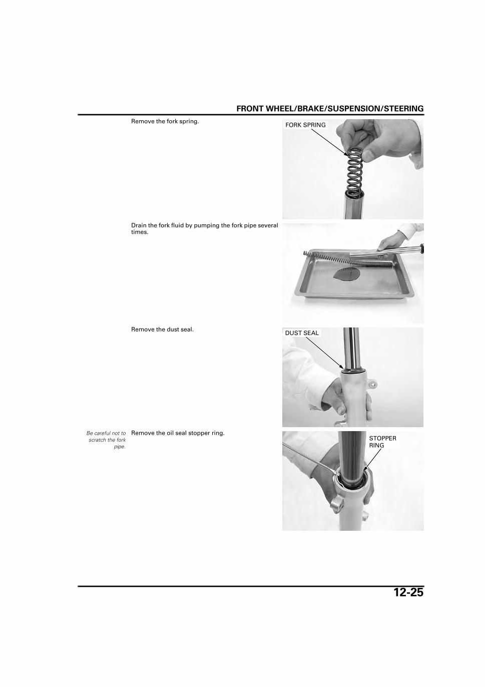
FRONT WHEEL/BRAKE/SUSPENSION/STEERING
12-25
Remove the fork spring.
Drain the fork fluid by pumping the fork pipe severaltimes.
Remove the dust seal.
Be careful not toscratch the fork
pipe.
Remove the oil seal stopper ring.
FORK SPRING
DUST SEAL
STOPPER RING

FRONT WHEEL/BRAKE/SUSPENSION/STEERING
12-26
Hold the fork slider in a vise with pieces of wood orshop towel.
Remove the fork socket bolt and sealing washer.
Remove the fork pipe from the fork slider.
Remove the oil lock piece from the fork slider.
Remove the fork piston and rebound spring fromthe fork pipe.
Remove the oil seal using the oil seal remover.
If the fork pistonturns with the
socket bolt, tempo-rarily install the forkspring and fork cap.
SOCKET BOLT/SEALING WASHER
FORK SLIDER
FORK SLIDER
OIL LOCK PIECE
FORK PIPE
FORK PIPE FORK PISTON
REBOUND SPRING
TOOL:
Oil seal remover 07748-0010001
OIL SEAL REMOVER
OIL SEAL
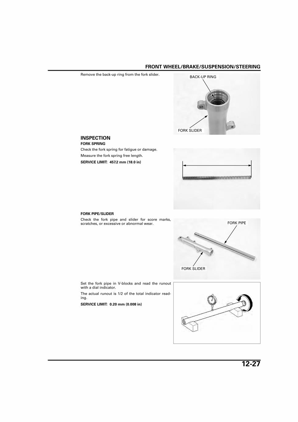
FRONT WHEEL/BRAKE/SUSPENSION/STEERING
12-27
Remove the back-up ring from the fork slider.
INSPECTIONFORK SPRING
Check the fork spring for fatigue or damage.
Measure the fork spring free length.
FORK PIPE/SLIDER
Check the fork pipe and slider for score marks,scratches, or excessive or abnormal wear.
Set the fork pipe in V-blocks and read the runoutwith a dial indicator.
The actual runout is 1/2 of the total indicator read-ing.
BACK-UP RING
FORK SLIDER
SERVICE LIMIT: 457.2 mm (18.0 in)
FORK PIPE
FORK SLIDER
SERVICE LIMIT: 0.20 mm (0.008 in)

FRONT WHEEL/BRAKE/SUSPENSION/STEERING
12-28
FORK PISTON
Check the fork piston for score marks, scratches, orexcessive or abnormal wear.
Check the rebound spring for fatigue or damage.
Check the piston ring for wear or damage.
Replace the front fork assembly if any componentsare worn or damaged.
FORK PIPE BUSHING/BACK-UP RING
Visually inspect the slider bushing.Replace the fork slider if they are worn, or if theTeflon coating is worn and 3/4 or over of the coppersurface appears.
Check the back-up ring and replace it if there is anydistortion at the points indicated by arrows on thefigure.
ASSEMBLYBefore assembly, wash all parts with a high flashpoint or non-flammable solvent and wipe them dry.
Install the rebound spring and fork piston into thefork pipe.
Install the oil lock piece onto the fork piston end.Apply fork fluid to the slider bushing surface.Install the fork pipe into the fork slider.
REBOUND SPRING
FORK PISTON
PISTON RING
BUSHING
CHECK POINTS
BACK-UP RING
COPPER SURFACE
FORK PIPE FORK PISTON
REBOUND SPRING
FORK SLIDER
OIL LOCK PIECE
FORK PIPE
SLIDER BUSHING SURFACE
FORK PISTON

FRONT WHEEL/BRAKE/SUSPENSION/STEERING
12-29
Clean the socket bolt threads and apply a lockingagent to the fork socket bolt threads and install itwith a new sealing washer.
Hold the fork slider in a vise with pieces of wood ora shop towel.
Tighten the socket bolt.
Install the back-up ring into the fork slider.
Apply fork fluid to a new oil seal lips, then install itinto the fork slider.Drive the oil seal into the fork slider using the spe-cial tools.
SEALING WASHER
SOCKET BOLT
If the fork pistonturns with the
socket bolt, tempo-rarily install the forkspring and fork cap.
SOCKET BOLT
FORK SLIDER
BACK-UP RING
FORK SLIDER
TOOLS:
Fork seal driver 07747-0010100
Fork seal driver attachment 07747-0010400
OIL SEAL
FORK SLIDER ATTACHMENT
DRIVER

FRONT WHEEL/BRAKE/SUSPENSION/STEERING
12-30
Install the oil seal stopper ring into the groove of thefork slider.
Install a new dust seal.
Pour the specified amount of recommended forkfluid into the fork pipe.
Pump the fork pipe several times to remove trappedair from the lower portion of the fork pipe.
Compress the fork leg fully and measure the oillevel from the top of the fork pipe.
Pull the fork pipe up and install the fork spring withits narrow pitched end facing down.
STOPPER RING
DUST SEAL
RECOMMENDED FLUID: Fork fluid
FORK FLUID CAPACITY:
65.0 cm3 (2.20 US oz, 2.29 lmp oz)
FLUID LEVEL: 159 mm (6.26 in)
FLUID LEVEL
Facing down

FRONT WHEEL/BRAKE/SUSPENSION/STEERING
12-31
Apply fork fluid to a new O-ring and install it ontothe fork cap.
Install the fork cap onto the fork pipe.
INSTALLATIONInsert the fork pipes into the bottom bridge.
Align the top end of the fork pipes with the uppersurface of the top bridge as shown.
Tighten the bottom pinch bolts to the specifiedtorque.
Tighten the fork caps to the specified torque.
Tighten the top pinch bolts to the specified torque.
Reposition the front cowl bracket and tighten thebolts.
Install the following:– Combination meter unit (page 18-6)– License plate holder (page 2-8)– Front fender (page 2-6)– Front wheel (type II and IV: page 12-19 or type I
and III: page 12-14)– Front cowl (page 2-7)
Install the brake caliper (page 14-18).
STEERING STEMREMOVALRemove the following:
– Front wheel (type II and IV: page 12-15 or type Iand III: page 12-11)
– Front cowl (page 2-7)– Combination meter (page 18-6)
Remove the bolts and front cowl bracket.
Tighten the fork capafter installing thefork pipe into the
fork bridges.
FORK CAP O-RING
TORQUE: 34 N·m (3.5 kgf·m, 25 lbf·ft)
TORQUE: 22 N·m (2.2 kgf·m, 16 lbf·ft)
BOTTOM PINCH BOLTS FORK CAP
Align
TORQUE: 23 N·m (2.3 kgf·m, 17 lbf·ft)
Type II and IV:
BOLTS TOP PINCH BOLTS
FRONT COWL BRACKET
BOLTS
FRONT COWL BRACKET

FRONT WHEEL/BRAKE/SUSPENSION/STEERING
12-32
Remove the bottom pinch bolts and side reflectorstay.
Remove the brake hose holder from the bottombridge.
Remove the handlebar (page 12-7).
Loosen the steering stem nut.
Remove the fork (page 12-24).
Remove the steering stem nut, washer and topbridge.
Loosen the adjusting nut using the special tool.
Type II and IV:
BOTTOM PINCH BOLTS
STAY
BRAKE HOSE HOLDER (Type II and IV only)
STEERING STEM NUT
STEERING STEM NUT
WASHER
TOP BRIDGE
TOOL:
Stem socket wrench 07916-3710101
ADJUSTING NUT

FRONT WHEEL/BRAKE/SUSPENSION/STEERING
12-33
When removing theadjusting nut, holdthe steering stem.
Remove the adjusting nut.
Remove the following:
– Top cone race– Upper steel balls (21)
Remove the following:
– Steering stem– Lower steel balls (21)
BALL RACE REPLACEMENTRemove the ball races using the special tool.
ADJUSTING NUT
TOP CONE RACE
UPPER STEEL BALL (21)
STEERING STEM
LOWER STEEL BALL (21)
TOOL:
Ball race remover 07944-1150001
TOP BALL RACE
BOTTOM BALL RACE
BALL RACE REMOVER
BALL RACE REMOVER

FRONT WHEEL/BRAKE/SUSPENSION/STEERING
12-34
Install a new top ball race using the special tools.
Install a new bottom ball race using the specialtools.
BOTTOM CONE RACE REPLACEMENTTo avoid damaging the steering stem thread, tem-porarily install the stem nut.Remove the bottom cone race, washer and dustseal.
Install the washer and new dust seal.Press a new bottom cone race onto the steeringstem using the special tool.
TOOLS:
Driver 07749-0010000
Attachment, 37 x 40 mm 07746-0010200
TOP BALL RACE
DRIVER
ATTACHMENT
TOOLS:
Driver 07749-0010000
Attachment, 37 x 40 mm 07746-0010200
BOTTOM BALL RACE
DRIVER
ATTACHMENT
STEERING STEM
BOTTOM CONE RACE/DUST SEAL/WASHER
STEM NUT
TOOL:
Steering stem driver 07946-GC40000
BOTTOM CONE RACE
DUST SEAL
DRIVER
WASHER

FRONT WHEEL/BRAKE/SUSPENSION/STEERING
12-35
INSTALLATION
Apply grease for extreme pressure to bearing areaand dust seal lip.Install the lower steel balls (21) in the bottom conerace.
Install the steering stem.
Apply grease for extreme pressure to bearing area.Install the upper steel balls (21) in the top ball race.
Install the top cone race.
BOTTOM CONE RACE
DUST SEAL
STEERING STEM
BOTTOM BALL RACE
TOP CONE RACE
LOWER STEEL BALLS (21)
ADJUSTING NUT GREASE FOR EXTREME PRESSURE
UPPER STEEL BALLS (21)
TOP BALL RACE WASHER
LOWER STEEL BALLS (21)
STEERING STEM
TOP CONE RACE
UPPER STEEL BALLS (21)

FRONT WHEEL/BRAKE/SUSPENSION/STEERING
12-36
Install the adjusting nut.
Tighten the adjusting nut to the specified torque.
Turn the steering stem left and right several times.
Temporarily loosen the adjusting nut completely,then retighten the adjusting nut to the specifiedtorque.
Check that there is no vertical play and that thesteering stem rotates smoothly.
ADJUSTING NUT
TOOL:
Stem socket wrench 07916-3710101
TORQUE: 25 N·m (2.5 kgf·m, 18 lbf·ft)
ADJUSTING NUT
TOOL:
Stem socket wrench 07916-3710101
TORQUE: 3.0 N·m (0.3 kgf·m, 2.2 lbf·ft)
ADJUSTING NUT

FRONT WHEEL/BRAKE/SUSPENSION/STEERING
12-37
Install the top bridge.
Install the washer and steering stem nut.
Loosen the bottompinch bolts when
tightening the stemnut.
Install the fork (page 12-31).
Tighten the steering stem nut to the specifiedtorque.
Install the handlebar (page 12-9).
Install the brake hose holder to the bottom bridge.
Install the side reflector stay and tighten the bottompinch bolts.
Install the front cowl bracket and tighten the bolts.
Install the following:
– Combination meter (page 18-6)– Front cowl (page 2-7)– Front wheel (type II and IV: page 12-19 or type I
and III: page 12-14)
STEERING STEM NUT
WASHER
TOP BRIDGE
TORQUE: 74 N·m (7.5 kgf·m, 55 lbf·ft)
STEERING STEM NUT
Type II and IV:
TORQUE: 34 N·m (3.5 kgf·m, 25 lbf·ft)
BOTTOM PINCH BOLTS
BRAKE HOSE HOLDER STAY
BOLTS
FRONT COWL BRACKET

FRONT WHEEL/BRAKE/SUSPENSION/STEERING
12-38
STEERING BEARING PRELOADRaise the front wheel off the ground.Position the steering stem to the straight aheadposition.Hook a spring scale to the fork pipe between thefork top and bottom bridges.Make sure that there is no cable or wire harnessinterference.Pull the spring scale keeping the scale at a rightangle to the steering stem.
Read the scale at the point where the steering stemjust starts to move.
If the readings do not fall within the limits, readjustthe steering top thread.
STEERING BEARING PRE-LOAD:
1.6 – 2.4 kgf (3.53 – 5.29 lbf)
90°

13-1
13
13. REAR WHEEL/BRAKE/SUSPENSION
SYSTEM COMPONENTS ···························· 13-2
SERVICE INFORMATION ···························· 13-3
TROUBLESHOOTING ·································· 13-5
REAR WHEEL ··············································· 13-6
REAR DRUM BRAKE ··································13-13
BRAKE PEDAL/CENTER STAND ···············13-16
SHOCK ABSORBER····································13-20
SWINGARM ················································13-21
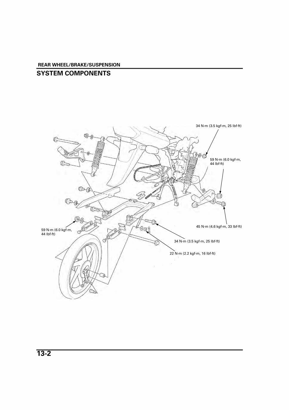
REAR WHEEL/BRAKE/SUSPENSION
13-2
REAR WHEEL/BRAKE/SUSPENSION
SYSTEM COMPONENTS
59 N·m (6.0 kgf·m, 44 lbf·ft)
45 N·m (4.6 kgf·m, 33 lbf·ft)
34 N·m (3.5 kgf·m, 25 lbf·ft)
34 N·m (3.5 kgf·m, 25 lbf·ft)
59 N·m (6.0 kgf·m, 44 lbf·ft)
22 N·m (2.2 kgf·m, 16 lbf·ft)

REAR WHEEL/BRAKE/SUSPENSION
13-3
SERVICE INFORMATIONGENERAL
• When servicing the rear wheel and suspension, support the motorcycle using a safety stand or hoist. • Use genuine Honda replacement bolts and nuts for all suspension pivots and mounting points.
SPECIFICATIONSUnit: mm (in)
TORQUE VALUES
Frequent inhalation of brake shoe dust, regardless of material composition could be hazardous to your health. • Avoid breathing dust particles. • Never use an air hose or brush to clean brake assemblies. Use an OSHA-approved vacuum cleaner.
ITEM STANDARD SERVICE LIMIT
Minimum tire tread depth – To wear indicatorCold tire pressure Driver only 225 kPa (2.25 kgf/cm2, 33 psi) –
Driver and passenger 225 kPa (2.25 kgf/cm2, 33 psi) –Axle runout – 0.2 (0.01)Wheel rim runout Radial – 1.0 (0.04)
Axial – 1.0 (0.04)Drive chain Size/link 428/108 –
Slack 10 – 20 (0.4 – 0.8) –Brake Pedal free play 20 – 30 (0.8 – 1.2) –
Drum I.D. 130.0 – 130.3 (5.12 – 5.13) 131.0 (5.16)
Driven sprocket bolt 34 N·m (3.5 kgf·m, 25 lbf·ft)Rear axle nut 59 N·m (6.0 kgf·m, 44 lbf·ft)Rear brake arm nut 10 N·m (1.0 kgf·m, 7 lbf·ft) U-nutRear brake stopper arm nut (swingarm side) 22 N·m (2.2 kgf·m, 16 lbf·ft)Rear brake stopper arm nut (rear brake panel side) 22 N·m (2.2 kgf·m, 16 lbf·ft)Shock absorber upper mounting nut 34 N·m (3.5 kgf·m, 25 lbf·ft)Shock absorber lower mounting bolt 34 N·m (3.5 kgf·m, 25 lbf·ft)Pillion step bracket bolt 45 N·m (4.6 kgf·m, 33 lbf·ft)Swingarm pivot nut 59 N·m (6.0 kgf·m, 44 lbf·ft)

REAR WHEEL/BRAKE/SUSPENSION
13-4
TOOLS
Pilot, 15 mm07746-0040300
Pilot, 20 mm07746-0040500
Attachment, 22 x 24 mm07746-0010800
Attachment, 32 x 35 mm07746-0010100
Attachment, 42 x 47 mm07746-0010300
Driver07749-0010000
Bearing remover shaft07746-0050100
Bearing remover head, 15 mm07746-0050400
REAR WHEEL/BRAKE/SUSPENSION
13-5
TROUBLESHOOTINGRear wheel wobbles • Bent rim • Worn or damaged rear wheel bearings • Faulty rear tire • Worn or damaged swingarm bushings • Bent frame or swingarm • Axle fastener not tightened properly • Tire pressure too low
Wheel turns hard • Brake drag • Faulty wheel bearings • Bent axle • Drive chain too tight (page 3-12)
Soft suspension • Incorrect suspension adjustment • Weak shock absorber springs • Oil leakage from damper unit • Low tire pressure
Hard suspension • Incorrect suspension adjustment • Bent shock absorber damper rod • Damaged suspension or swingarm pivot bushings • Bent swingarm pivot or frame • High tire pressure
Steers to one side or does not track straight • Drive chain adjusters not adjusted equally • Bent axle • Bent frame • Worn swingarm pivot components
Rear suspension noise • Loose suspension fasteners • Worn or damaged suspension pivot bushings • Faulty shock absorber

REAR WHEEL/BRAKE/SUSPENSION
13-6
REAR WHEELREMOVALRaise the rear wheel off the ground by placing awork stand or box under the frame.
Disconnect the brake rod by removing the adjustingnut, and remove the spring and joint pin.
Remove the following:
– Cotter pin– Nut– Washer– Joint bolt– Brake panel stopper arm
Loosen the axle nut.
Loosen the both drive chain adjuster lock nuts andadjusting bolts so the wheel can be moved all theway forward. Move the wheel forward for maxi-mum chain slack.
Derail the drive chain from the driven sprocket.
Remove the following: – Axle nut– Axle– Both adjusters and adjuster plates– Collar– Rear wheel
Remove the brake panel assembly.
SPRING
JOINT PIN
ADJUSTING NUT ROD
WASHER
COTTER PIN
NUT
BOLT
STOPPER ARM
CHAIN
ADJUSTERAXLE
COLLAR
ADJUSTING BOLT
NUT
ADJUSTER PLATE
LOCK NUT
BRAKE PANEL
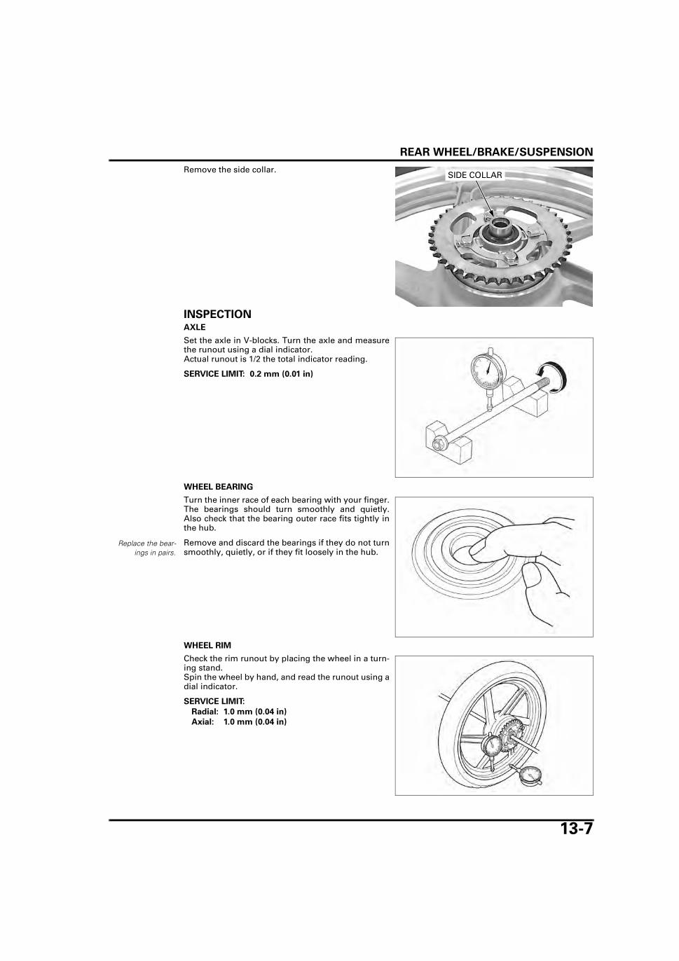
REAR WHEEL/BRAKE/SUSPENSION
13-7
Remove the side collar.
INSPECTIONAXLE
Set the axle in V-blocks. Turn the axle and measurethe runout using a dial indicator.Actual runout is 1/2 the total indicator reading.
WHEEL BEARING
Turn the inner race of each bearing with your finger.The bearings should turn smoothly and quietly.Also check that the bearing outer race fits tightly inthe hub.
Remove and discard the bearings if they do not turnsmoothly, quietly, or if they fit loosely in the hub.
WHEEL RIM
Check the rim runout by placing the wheel in a turn-ing stand.Spin the wheel by hand, and read the runout using adial indicator.
SIDE COLLAR
SERVICE LIMIT: 0.2 mm (0.01 in)
Replace the bear-ings in pairs.
SERVICE LIMIT:
Radial: 1.0 mm (0.04 in)
Axial: 1.0 mm (0.04 in)

REAR WHEEL/BRAKE/SUSPENSION
13-8
DRIVEN SPROCKET
Check the condition of the driven sprocket teeth.Replace the sprocket if it is worn or damaged.
• If the driven sprocket requires replacement,inspect the drive chain and drive sprocket.
• Never install a new drive chain on a wornsprocket or a worn chain on new sprockets. Bothchain and sprocket must be in good condition, orthe replacement chain or sprocket will wear rap-idly.
DISASSEMBLYDRIVEN SPROCKET
Remove the driven flange assembly from the rearwheel.
Remove the four damper rubbers and O-ring.
Bend down the lock plate tabs so that the bolts canbe loosened.
Remove the following: – Four bolts– Lock plates– Four nuts– Driven sprocket– Dust seal
DAMAGE
WEAR
NORMAL
DRIVEN FLANGE ASSEMBLY
DAMPER RUBBER
O-RING
DRIVEN SPROCKET
DUST SEAL
BOLTS/TABS/NUTS
LOCK PLATE
LOCK PLATE
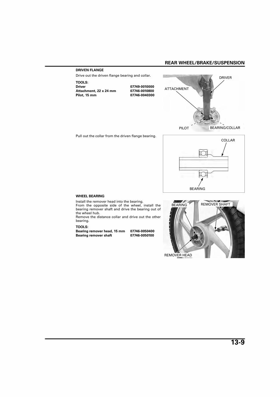
REAR WHEEL/BRAKE/SUSPENSION
13-9
DRIVEN FLANGE
Drive out the driven flange bearing and collar.
Pull out the collar from the driven flange bearing.
WHEEL BEARING
Install the remover head into the bearing.From the opposite side of the wheel, install thebearing remover shaft and drive the bearing out ofthe wheel hub.Remove the distance collar and drive out the otherbearing.
TOOLS:
Driver 07749-0010000
Attachment, 22 x 24 mm 07746-0010800
Pilot, 15 mm 07746-0040300
DRIVER
ATTACHMENT
PILOT BEARING/COLLAR
COLLAR
BEARING
TOOLS:
Bearing remover head, 15 mm 07746-0050400
Bearing remover shaft 07746-0050100
REMOVER HEAD
REMOVER SHAFTBEARING
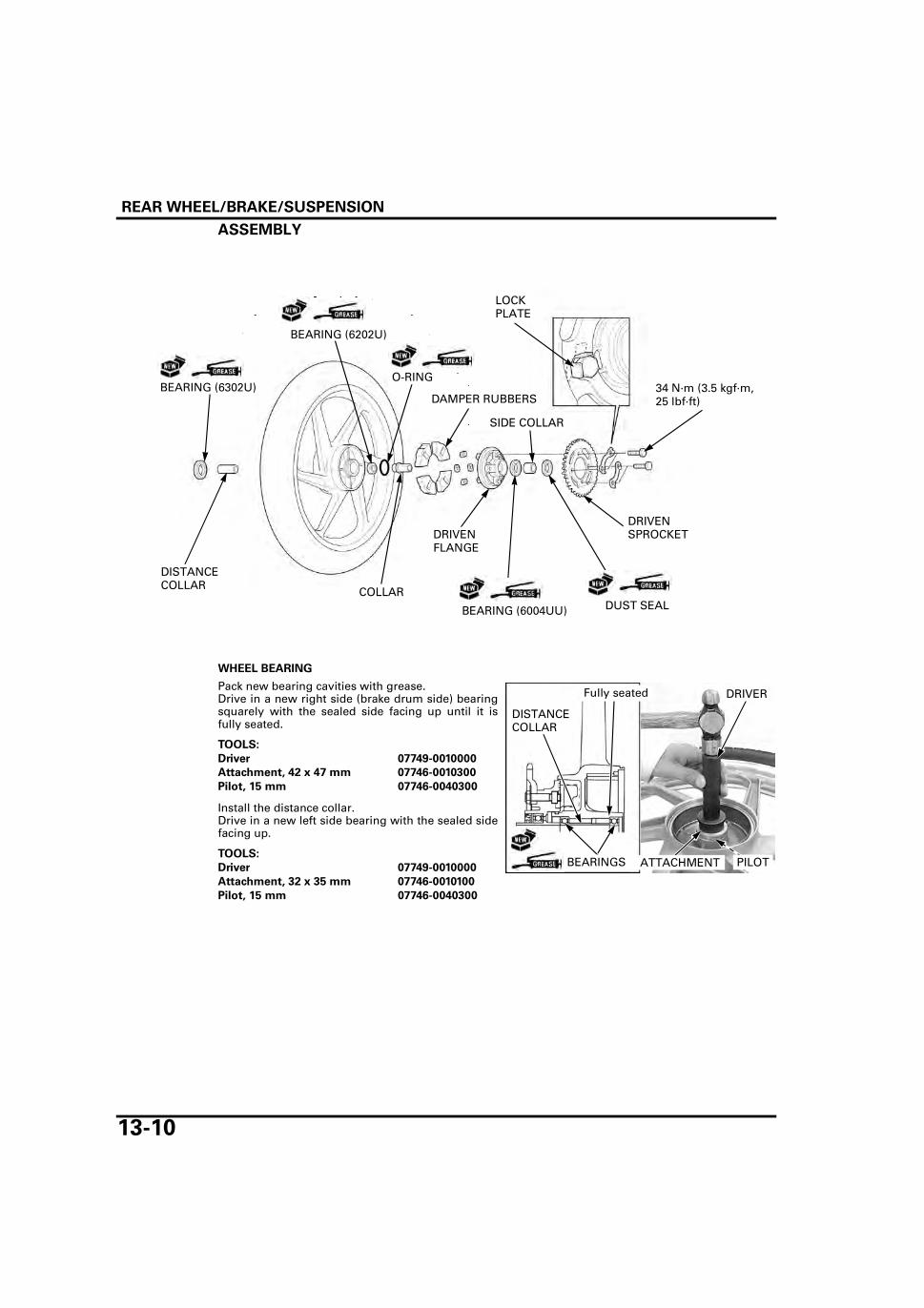
REAR WHEEL/BRAKE/SUSPENSION
13-10
ASSEMBLY
WHEEL BEARING
Pack new bearing cavities with grease.Drive in a new right side (brake drum side) bearingsquarely with the sealed side facing up until it isfully seated.
Install the distance collar.Drive in a new left side bearing with the sealed sidefacing up.
BEARING (6004UU)
BEARING (6302U)
COLLAR
34 N·m (3.5 kgf·m, 25 lbf·ft)
SIDE COLLAR
DISTANCE COLLAR
DAMPER RUBBERS
O-RING
BEARING (6202U)
LOCK PLATE
DRIVEN SPROCKET DRIVEN
FLANGE
DUST SEAL
TOOLS:
Driver 07749-0010000
Attachment, 42 x 47 mm 07746-0010300
Pilot, 15 mm 07746-0040300
TOOLS:
Driver 07749-0010000
Attachment, 32 x 35 mm 07746-0010100
Pilot, 15 mm 07746-0040300
DRIVER
ATTACHMENT PILOTBEARINGS
Fully seated
DISTANCE COLLAR
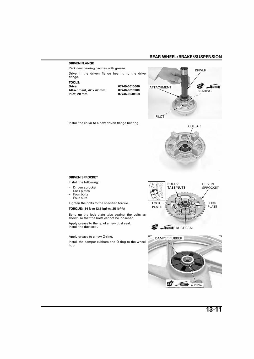
REAR WHEEL/BRAKE/SUSPENSION
13-11
DRIVEN FLANGE
Pack new bearing cavities with grease.
Drive in the driven flange bearing to the driveflange.
Install the collar to a new driven flange bearing.
DRIVEN SPROCKET
Install the following:
– Driven sprocket– Lock plates– Four bolts– Four nuts
Tighten the bolts to the specified torque.
Bend up the lock plate tabs against the bolts asshown so that the bolts cannot be loosened.
Apply grease to the lip of a new dust seal.Install the dust seal.
Apply grease to a new O-ring.
Install the damper rubbers and O-ring to the wheelhub.
TOOLS:
Driver 07749-0010000
Attachment, 42 x 47 mm 07746-0010300
Pilot, 20 mm 07746-0040500
DRIVER
ATTACHMENT
PILOT
BEARING
COLLAR
TORQUE: 34 N·m (3.5 kgf·m, 25 lbf·ft)
DRIVEN SPROCKET
DUST SEAL
BOLTS/TABS/NUTS
LOCK PLATE
LOCK PLATE
DAMPER RUBBER
O-RING

REAR WHEEL/BRAKE/SUSPENSION
13-12
Install the driven flange assembly to the rear wheel.
INSTALLATIONInstall the side collar.
Do not get greaseon the brake drum
and shoe linings.
Install the brake panel into the wheel hub.
Place the rear wheel in the swingarm.
Install the drive chain over the driven sprocket.
Install both adjuster and adjuster plate to the swing-arm.
Insert the axle from the right side through the swin-garm, collar and wheel.
Adjust the drive chain slack (page 3-12).
Tighten the axle nut to the specified torque.
DRIVEN FLANGE ASSEMBLY
SIDE COLLAR
BRAKE PANEL
TORQUE: 59 N·m (6.0 kgf·m, 44 lbf·ft)
CHAIN
ADJUSTERAXLE
COLLAR
ADJUSTER PLATE
NUT

REAR WHEEL/BRAKE/SUSPENSION
13-13
Install the following:
– Brake panel stopper arm– Joint bolt– Washer
Install and tighten the nut to the specified torque.
Install the new cotter pin.
Install the spring onto the brake rod and the jointpin into the brake arm.Connect the brake rod to the brake arm with theadjusting nut.
Adjust the brake pedal free play (page 3-17).
Inspect the rear brake light operation.
REAR DRUM BRAKEINSPECTIONRemove the rear wheel (page 13-6).
Measure the rear brake drum I.D.
DISASSEMBLYRemove the brake panel (page 13-6).
Expand the brake shoes and remove them from thebrake panel.
Remove the shoe springs from the brake shoes.
TORQUE: 22 N·m (2.2 kgf·m, 16 lbf·ft)
WASHER
COTTER PIN
NUT
BOLT
STOPPER ARM
SPRING
JOINT PIN
ADJUSTING NUT ROD
BRAKE ARM
SERVICE LIMIT: 131.0 mm (5.16 in)
Always replace thebrake shoes in
pairs.
BRAKE SHOES
SPRINGS

REAR WHEEL/BRAKE/SUSPENSION
13-14
Remove the following:
– Nut and bolt– Brake arm– Wear indicator– Brake cam
Remove the felt seal.
ASSEMBLY
BOLT
INDICATOR
BRAKE ARM
NUT
BRAKE CAM
FELT SEAL
SHOE SPRING BRAKE SHOE
BRAKE CAM
INDICATOR
FELT SEAL
BRAKE ARM
BRAKE PANEL
10 N·m (1.0 kgf·m, 7 lbf·ft)
GEAR OIL

REAR WHEEL/BRAKE/SUSPENSION
13-15
Apply gear oil to a new felt seal and install it.
Apply grease to the sliding surface of the brakecam.Install the brake cam to the brake panel.
Install the wear indicator, aligning the wide toothwith the wide groove in the brake cam.
Install the brake arm, aligning the punch marks ofthe brake cam and the brake arm.
FELT SEAL
GEAR OIL
BRAKE CAM
BRAKE PANEL
INDICATOR BRAKE CAM
Align
BRAKE ARM
Align
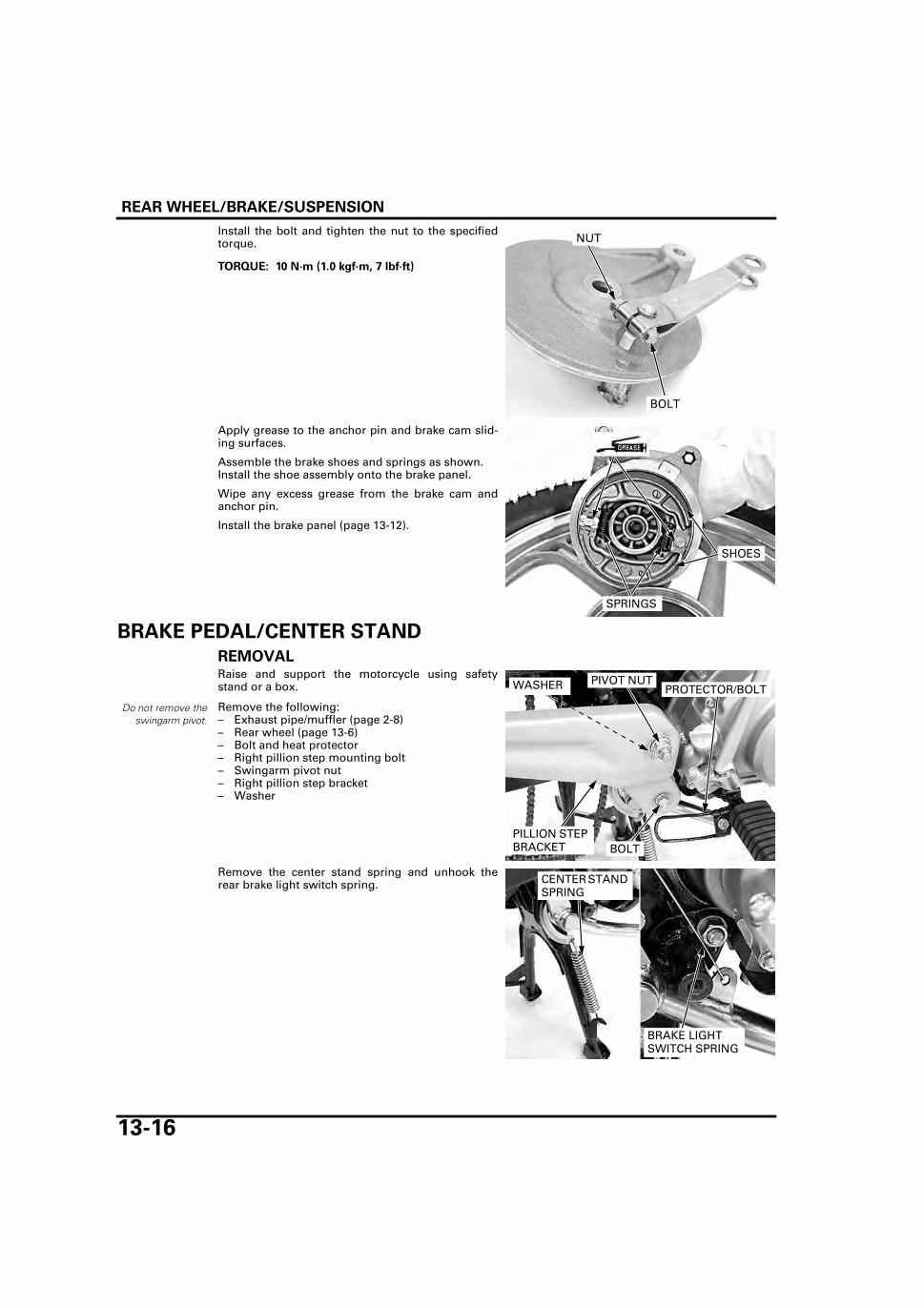
REAR WHEEL/BRAKE/SUSPENSION
13-16
Install the bolt and tighten the nut to the specifiedtorque.
Apply grease to the anchor pin and brake cam slid-ing surfaces.
Assemble the brake shoes and springs as shown.Install the shoe assembly onto the brake panel.
Wipe any excess grease from the brake cam andanchor pin.
Install the brake panel (page 13-12).
BRAKE PEDAL/CENTER STAND
REMOVALRaise and support the motorcycle using safetystand or a box.
Remove the following:– Exhaust pipe/muffler (page 2-8)– Rear wheel (page 13-6)– Bolt and heat protector– Right pillion step mounting bolt– Swingarm pivot nut– Right pillion step bracket– Washer
Remove the center stand spring and unhook therear brake light switch spring.
TORQUE: 10 N·m (1.0 kgf·m, 7 lbf·ft)
BOLT
NUT
SPRINGS
SHOES
Do not remove theswingarm pivot.
PIVOT NUT
PILLION STEP BRACKET BOLT
PROTECTOR/BOLTWASHER
BRAKE LIGHT SWITCH SPRING
CENTER STAND SPRING

REAR WHEEL/BRAKE/SUSPENSION
13-17
Remove the rear brake return spring.
Remove the left pillion step bracket mounting boltand rotate the left pillion step bracket so that thecenter stand pivot is accessible.
Remove the cotter pin and washer from the centerstand pivot.
Pull out the pivot and remove the center stand andrear brake pedal.
Remove the following:
– Cotter pin– Washer– Brake rod
BRAKE RETURN SPRING
PILLION STEP BRACKET
BOLT
COTTER PIN
CENTER STAND PIVOT
WASHER
COTTER PIN
WASHER
BRAKE ROD

REAR WHEEL/BRAKE/SUSPENSION
13-18
INSTALLATION
Connect the brake rod to the pedal with the washerand a new cotter pin.
Apply grease to the center stand pivot.
Install the following:– Center stand– Brake pedal– Center stand pivot– Washer
Install a new cotter pin.
COTTER PIN WASHER
BRAKE ROD
PROTECTOR
BRAKE PEDAL
CENTER STAND PIVOTCENTER STAND SPRING
BRAKE LIGHT SWITCH SPRING
CENTER STAND
COTTER PIN
WASHER
BRAKE ROD
COTTER PIN
CENTER STAND PIVOT
WASHER

REAR WHEEL/BRAKE/SUSPENSION
13-19
Rotate the left pillion step bracket back to its originalposition.
Install the left pillion step bracket mounting bolt.
Install the rear brake return spring.
Install the center stand spring and hook the rearbrake light switch spring to rear brake pedal.
Set the washer to the swingarm pivot and install theright pillion step bracket and right pillion stepbracket mounting bolt.
Install and tighten the swingarm pivot nut to thespecified torque.
Tighten the right and left pillion step bracket bolts tothe specified torque.
Install the heat protector and tighten the bolt.
Install the following:– Rear wheel (page 13-12)– Exhaust pipe/muffler (page 2-9)
PILLION STEP BRACKET
BOLT
BRAKE RETURN SPRING
BRAKE LIGHT SWITCH SPRING
CENTER STAND SPRING
TORQUE: 59 N·m (6.0 kgf·m, 44 lbf·ft)
TORQUE: 45 N·m (4.6 kgf·m, 33 lbf·ft)
NUT
PILLION STEP BRACKET BOLT
PROTECTOR/BOLTWASHER

REAR WHEEL/BRAKE/SUSPENSION
13-20
SHOCK ABSORBER
REMOVALRemove the exhaust pipe/muffler (page 2-8).
Place the motorcycle on its center stand.
Remove the upper mounting nut and washer.
Remove the lower mounting bolt and shockabsorber.
INSPECTIONReplace the shock
absorber as anassembly.
Visually inspect the shock absorber for wear ordamage.
Check the following:– Damper rod for bending or damage– Damper unit for leakage or other damage– Bushing for wear or damage
Check for smooth damper operation.
INSTALLATIONInstall the shock absorber and lower mounting bolt.
Install the washer and upper mounting nut.
Tighten the upper mounting nut and lower mount-ing bolt to the specified torque.
Install the exhaust pipe/muffler (page 2-9).
UPPER MOUNTING NUT/WASHER
SHOCK ABSORBER
LOWER MOUNTING BOLT
SHOCK ABSORBER
TORQUE:
Shock absorber upper mounting nut: 34 N·m (3.5 kgf·m, 25 lbf·ft)
Shock absorber lower mounting bolt: 34 N·m (3.5 kgf·m, 25 lbf·ft)
UPPER MOUNTING NUT/WASHER
SHOCK ABSORBER
LOWER MOUNTING BOLT
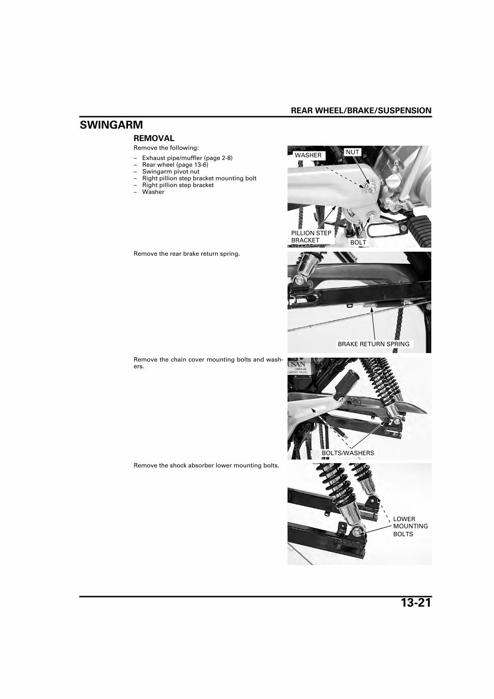
REAR WHEEL/BRAKE/SUSPENSION
13-21
SWINGARM
REMOVALRemove the following:
– Exhaust pipe/muffler (page 2-8)– Rear wheel (page 13-6)– Swingarm pivot nut– Right pillion step bracket mounting bolt– Right pillion step bracket– Washer
Remove the rear brake return spring.
Remove the chain cover mounting bolts and wash-ers.
Remove the shock absorber lower mounting bolts.
NUT
PILLION STEP BRACKET BOLT
WASHER
BRAKE RETURN SPRING
BOLTS/WASHERS
LOWER MOUNTING BOLTS

REAR WHEEL/BRAKE/SUSPENSION
13-22
Remove the following:
– Left pillion step bracket mounting bolt– Swingarm pivot– Left pillion step bracket– Washer– Swingarm
DISASSEMBLYRemove the following:
– Cotter pin– Nut– Washer– Joint bolt– Brake panel stopper arm
Remove the chain slider.
INSPECTIONCheck the swingarm for cracks or other damage.
Check the pivot bushing for wear, deterioration ordamage.
PILLION STEP BRACKET
BOLT
PIVOT
SWINGARM
WASHER
WASHER
COTTER PIN
NUT
BOLT
STOPPER ARM
CHAIN SLIDER
BUSHING

REAR WHEEL/BRAKE/SUSPENSION
13-23
ASSEMBLYInstall the chain slider aligning the tab and the swin-garm groove.
Install the following:
– Brake panel stopper arm– Joint bolt– Washer
Install and tighten the nut to the specified torque.
Install the new cotter pin.
INSTALLATIONInstall the following:
– Swingarm– Washer– Left pillion step bracket– Swingarm pivot– Left pillion step bracket mounting bolt
Install and tighten the shock absorber lower mount-ing bolts to the specified torque.
TAB
GROOVE
CHAIN SLIDER
TORQUE: 22 N·m (2.2 kgf·m, 16 lbf·ft)
WASHER
COTTER PIN
NUT
BOLT
STOPPER ARM
PILLION STEP BRACKET
BOLT
PIVOT
SWINGARM
WASHER
TORQUE: 34 N·m (3.5 kgf·m, 25 lbf·ft)
LOWER MOUNTING BOLTS

REAR WHEEL/BRAKE/SUSPENSION
13-24
Install the chain cover mounting bolts and washers.
Install the rear brake return spring.
Set the washer to the swingarm pivot and install theright pillion step bracket and the mounting bolt.
Install and tighten the swingarm pivot nut to thespecified torque.
Tighten the right and left pillion step bracket bolts tothe specified torque.
Install the following:
– Rear wheel (page 13-12)– Exhaust pipe/muffler (page 2-9)
BOLTS/WASHERS
BRAKE RETURN SPRING
TORQUE: 59 N·m (6.0 kgf·m, 44 lbf·ft)
TORQUE: 45 N·m (4.6 kgf·m, 33 lbf·ft)
NUT
PILLION STEP BRACKET BOLT
WASHER

14-1
14
14. HYDRAULIC BRAKE
SYSTEM COMPONENTS ···························· 14-2
SERVICE INFORMATION ···························· 14-3
TROUBLESHOOTING ·································· 14-4
BRAKE FLUID REPLACEMENT/AIR BLEEDING ············································· 14-5
BRAKE PAD/DISC·········································14-7
MASTER CYLINDER ···································14-10
BRAKE CALIPER ·········································14-15
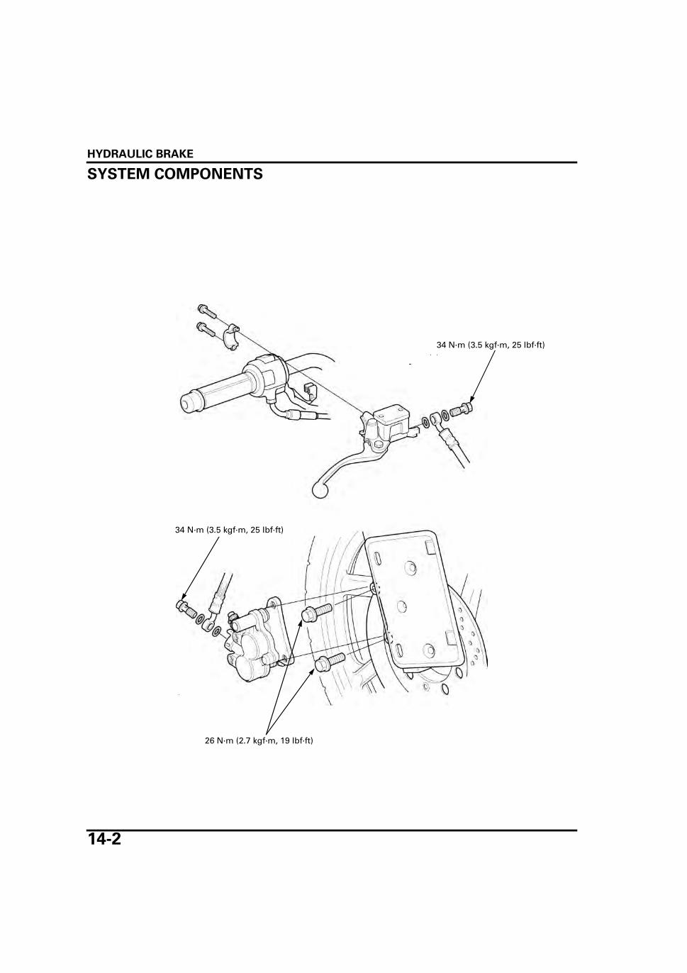
HYDRAULIC BRAKE
14-2
HYDRAULIC BRAKE
SYSTEM COMPONENTS
34 N·m (3.5 kgf·m, 25 lbf·ft)
26 N·m (2.7 kgf·m, 19 lbf·ft)
34 N·m (3.5 kgf·m, 25 lbf·ft)
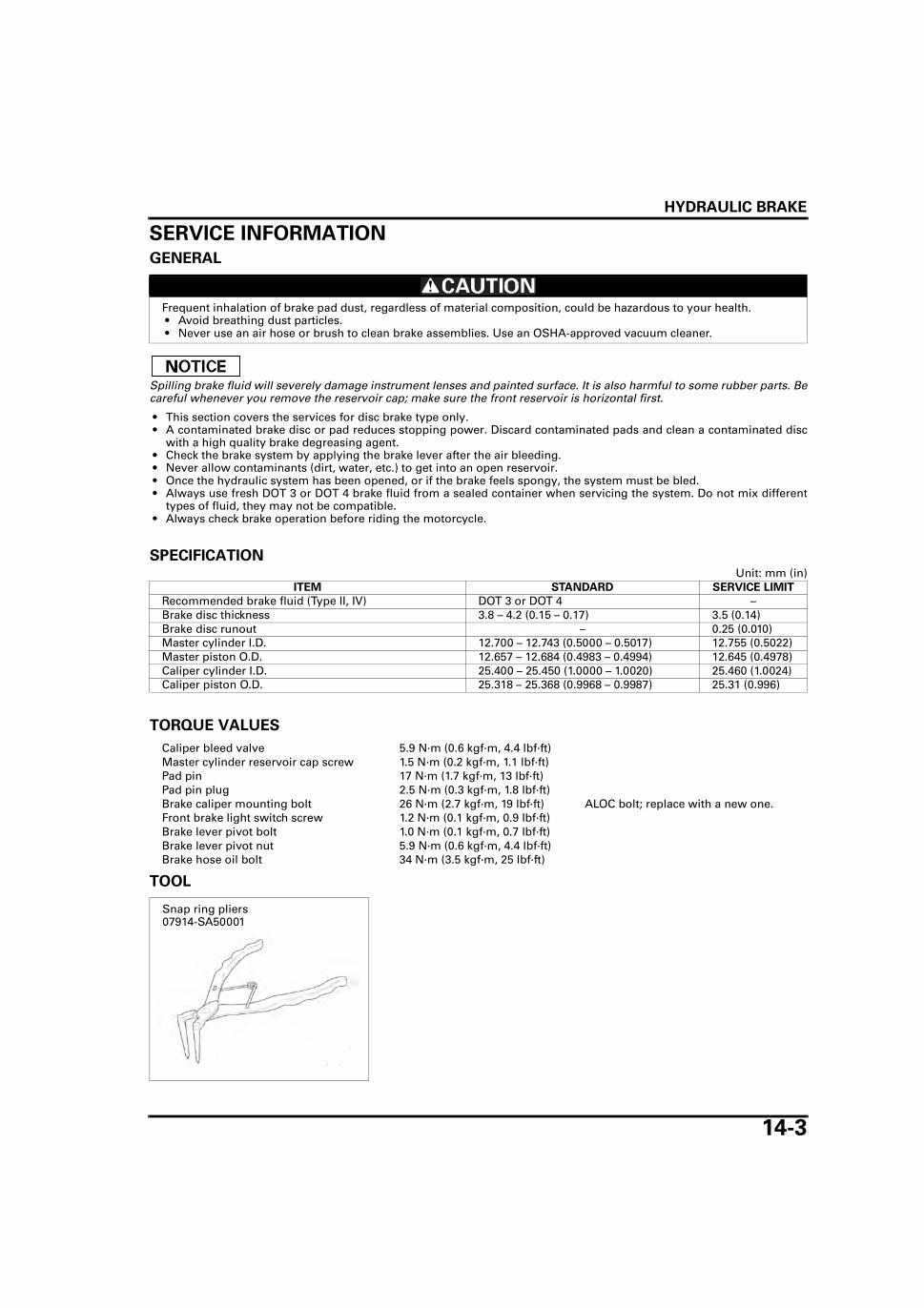
HYDRAULIC BRAKE
14-3
SERVICE INFORMATIONGENERAL
Spilling brake fluid will severely damage instrument lenses and painted surface. It is also harmful to some rubber parts. Becareful whenever you remove the reservoir cap; make sure the front reservoir is horizontal first.
• This section covers the services for disc brake type only. • A contaminated brake disc or pad reduces stopping power. Discard contaminated pads and clean a contaminated disc
with a high quality brake degreasing agent. • Check the brake system by applying the brake lever after the air bleeding. • Never allow contaminants (dirt, water, etc.) to get into an open reservoir. • Once the hydraulic system has been opened, or if the brake feels spongy, the system must be bled. • Always use fresh DOT 3 or DOT 4 brake fluid from a sealed container when servicing the system. Do not mix different
types of fluid, they may not be compatible. • Always check brake operation before riding the motorcycle.
SPECIFICATIONUnit: mm (in)
TORQUE VALUES
TOOL
Frequent inhalation of brake pad dust, regardless of material composition, could be hazardous to your health. • Avoid breathing dust particles. • Never use an air hose or brush to clean brake assemblies. Use an OSHA-approved vacuum cleaner.
ITEM STANDARD SERVICE LIMIT
Recommended brake fluid (Type II, IV) DOT 3 or DOT 4 –Brake disc thickness 3.8 – 4.2 (0.15 – 0.17) 3.5 (0.14)Brake disc runout – 0.25 (0.010)Master cylinder I.D. 12.700 – 12.743 (0.5000 – 0.5017) 12.755 (0.5022)Master piston O.D. 12.657 – 12.684 (0.4983 – 0.4994) 12.645 (0.4978)Caliper cylinder I.D. 25.400 – 25.450 (1.0000 – 1.0020) 25.460 (1.0024)Caliper piston O.D. 25.318 – 25.368 (0.9968 – 0.9987) 25.31 (0.996)
Caliper bleed valve 5.9 N·m (0.6 kgf·m, 4.4 lbf·ft)Master cylinder reservoir cap screw 1.5 N·m (0.2 kgf·m, 1.1 lbf·ft)Pad pin 17 N·m (1.7 kgf·m, 13 lbf·ft)Pad pin plug 2.5 N·m (0.3 kgf·m, 1.8 lbf·ft)Brake caliper mounting bolt 26 N·m (2.7 kgf·m, 19 lbf·ft) ALOC bolt; replace with a new one.Front brake light switch screw 1.2 N·m (0.1 kgf·m, 0.9 lbf·ft)Brake lever pivot bolt 1.0 N·m (0.1 kgf·m, 0.7 lbf·ft)Brake lever pivot nut 5.9 N·m (0.6 kgf·m, 4.4 lbf·ft)Brake hose oil bolt 34 N·m (3.5 kgf·m, 25 lbf·ft)
Snap ring pliers07914-SA50001

HYDRAULIC BRAKE
14-4
TROUBLESHOOTINGBrake lever soft or spongy • Air in hydraulic system • Leaking hydraulic system • Contaminated brake pad/disc • Worn caliper piston seal • Worn master cylinder piston cups • Worn brake pad/disc • Contaminated caliper • Contaminated master cylinder • Caliper not sliding properly • Low brake fluid level • Clogged fluid passage • Warped/deformed brake disc • Sticking/worn caliper piston • Sticking/worn master cylinder piston • Bent brake lever
Brake lever hard • Clogged/restricted brake system • Sticking/worn caliper piston • Caliper not sliding properly • Worn caliper piston seal • Sticking/worn master cylinder piston • Bent brake lever
Brake drags • Contaminated brake pad/disc • Misaligned wheel • Badly worn brake pad/disc • Warped/deformed brake disc • Caliper not sliding properly • Clogged/restricted fluid passage • Sticking caliper piston
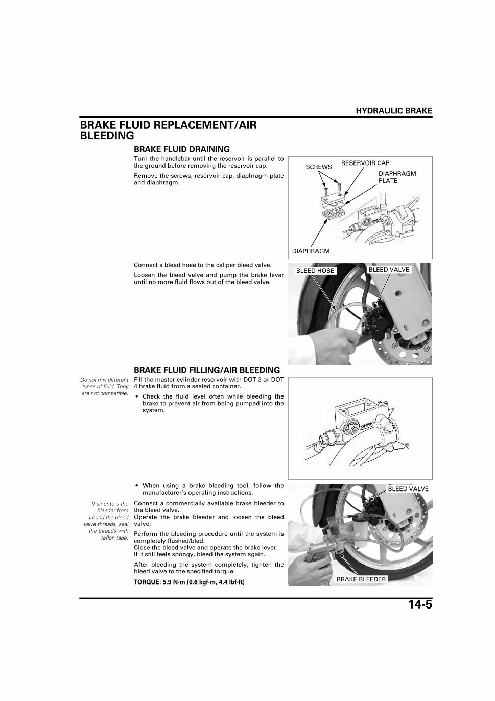
HYDRAULIC BRAKE
14-5
BRAKE FLUID REPLACEMENT/AIR BLEEDING
BRAKE FLUID DRAININGTurn the handlebar until the reservoir is parallel tothe ground before removing the reservoir cap.
Remove the screws, reservoir cap, diaphragm plateand diaphragm.
Connect a bleed hose to the caliper bleed valve.
Loosen the bleed valve and pump the brake leveruntil no more fluid flows out of the bleed valve.
BRAKE FLUID FILLING/AIR BLEEDINGDo not mix differenttypes of fluid. Theyare not compatible.
Fill the master cylinder reservoir with DOT 3 or DOT4 brake fluid from a sealed container.
• Check the fluid level often while bleeding thebrake to prevent air from being pumped into thesystem.
• When using a brake bleeding tool, follow themanufacturer’s operating instructions.
Connect a commercially available brake bleeder tothe bleed valve.Operate the brake bleeder and loosen the bleedvalve.
Perform the bleeding procedure until the system iscompletely flushed/bled.Close the bleed valve and operate the brake lever.If it still feels spongy, bleed the system again.
After bleeding the system completely, tighten thebleed valve to the specified torque.
SCREWSDIAPHRAGM PLATE
DIAPHRAGM
RESERVOIR CAP
BLEED VALVEBLEED HOSE
If air enters thebleeder from
around the bleedvalve threads, seal
the threads withteflon tape.
TORQUE: 5.9 N·m (0.6 kgf·m, 4.4 lbf·ft) BRAKE BLEEDER
BLEED VALVE

HYDRAULIC BRAKE
14-6
If the brake bleeder is not available, perform the fol-lowing procedure.
Pump up the system pressure with the brake leveruntil the lever resistance is felt.
Connect a bleed hose to the bleed valve and bleedthe system as follows:
1. Squeeze the brake lever all the way and loosenthe bleed valve 1/2 of a turn. Wait several sec-onds and then close the bleed valve.
2. Release the brake lever slowly and wait severalseconds after it reaches the end of its travel.
3. Repeat the steps 1 and 2 until there are no airbubbles in the bleed hose.
After bleeding the system completely, tighten thebleed valve to the specified torque.
Do not mix differenttypes of fluid. Theyare not compatible.
Fill the reservoir to the casting ledge with DOT 3 orDOT 4 brake fluid from a sealed container.
Install the diaphragm, diaphragm plate and reser-voir cap, then tighten the screws to the specifiedtorque.
BRAKE LEVER
Do not release thebrake lever until the
bleed valve isclosed.
TORQUE: 5.9 N·m (0.6 kgf·m, 4.4 lbf·ft)
BLEED VALVEBLEED HOSE
CASTING LEDGE
TORQUE: 1.5 N·m (0.2 kgf·m, 1.1 lbf·ft)
SCREWSDIAPHRAGM PLATE
DIAPHRAGM
RESERVOIR CAP

HYDRAULIC BRAKE
14-7
BRAKE PAD/DISC
BRAKE PAD REPLACEMENTCheck the fluid
level in the mastercylinder reservoir as
this operationcauses the fluid
level to rise.
Remove the license plate holder (page 2-8).
Push the caliper pistons all the way in by pushingthe caliper body inward to allow installation of newbrake pads.
Remove the pad pin plug.
Loosen the pad pins.
Remove the caliper mounting bolts and brake cali-per.
Remove the pad pins.
CALIPER BODY
PAD PIN PLUG
PAD PINS
MOUNTING BOLTS
BRAKE CALIPER
PAD PIN

HYDRAULIC BRAKE
14-8
Remove the brake pads.
Make sure the pad spring is installed in position.
Always replace thebrake pads in pairs.
Install the new brake pads.
Install the pad pin by pushing the pads against thepad spring to align the pad pin holes of the padsand caliper.
BRAKE PADS
PAD SPRING
BRAKE PADS
PAD PIN

HYDRAULIC BRAKE
14-9
Install the brake caliper and new mounting bolts.Tighten the brake caliper mounting bolts to thespecified torque.
Tighten the pad pins to the specified torque.
Operate the brake lever to seat the caliper pistonsagainst the pads.
Install and tighten the pad pin plugs to the specifiedtorque.
Install the license plate holder (page 2-8).
BRAKE DISC INSPECTIONVisually inspect the brake disc for damage or crack.
Measure the brake disc thickness at several points.
Replace the brake disc if the smallest measurementis less than service limit.
Check the brake disc for runout.
Check the wheel bearings for excessive play, if thewarpage exceeds the service limit.Replace the brake disc if the wheel bearings are nor-mal.
TORQUE: 26 N·m (2.7 kgf·m, 19 lbf·ft)
TORQUE: 17 N·m (1.7 kgf·m, 13 lbf·ft) PAD PINS
MOUNTING BOLTS
BRAKE CALIPER
TORQUE: 2.5 N·m (0.3 kgf·m, 1.8 lbf·ft)
PAD PIN PLUGS
SERVICE LIMIT: 3.5 mm (0.14 in)
SERVICE LIMIT: 0.25 mm (0.010 in)

HYDRAULIC BRAKE
14-10
MASTER CYLINDER
REMOVALDrain the brake fluid from the hydraulic system(page 14-5).
Remove the right rear view mirror (page 12-7).
Remove the screws, reservoir cap, diaphragm plateand diaphragm.
Disconnect the brake light switch connectors.
Disconnect the brake hose from the master cylinderby removing the oil bolt and sealing washers.
Remove the master cylinder holder bolts, holderand master cylinder.
DISASSEMBLYRemove the brake lever pivot nut, bolt and brakelever.
SCREWSDIAPHRAGM PLATE
DIAPHRAGM
RESERVOIR CAP
CONNECTORS
OIL BOLT
BRAKE HOSE
SEALING WASHERS
BOLTS
HOLDER
MASTER CYLINDER
BOLT
BRAKE LEVER
NUT

HYDRAULIC BRAKE
14-11
Remove the screw and brake light switch.
Remove the boot from the master piston.
Remove the snap ring using the special tool.
Remove the master piston and spring.
Clean the master cylinder, reservoir and master pis-ton in clean brake fluid.
BRAKE LIGHT SWITCHSCREW
BOOT
MASTER PISTON
TOOL:
Snap ring pliers 07914-SA50001
SNAP RING
MASTER PISTON
SPRING

HYDRAULIC BRAKE
14-12
INSPECTIONCheck the master piston for scoring, scratches ordamage.
Check the piston cups for wear, deterioration ordamage.
Check the master cylinder for scoring, scratches ordamage.
Measure the master cylinder I.D.
Measure the master piston O.D.
MASTER CYLINDER
MASTER PISTON
PISTON CUPS
SERVICE LIMIT: 12.755 mm (0.5022 in)
SERVICE LIMIT: 12.645 mm (0.4978 in)

HYDRAULIC BRAKE
14-13
ASSEMBLY
Keep the piston,cups, spring, snapring and boot as aset; do not substi-
tute individual part.
Coat a new piston cups and piston with clean DOT 3or DOT 4 brake fluid.
Install the spring onto the piston end.
Install the spring, master piston and washer into themaster cylinder.
Be certain the snapring is firmly seated
in the groove.
Install the snap ring into the groove in the mastercylinder.
SNAP RING
BOOT
MASTER CYLINDER
BRAKE LEVER
RESERVOIR CAP
DIAPHRAGM
PISTON CUPS
PIVOT BOLT
MASTER PISTON DIAPHRAGM
PLATE
1.5 N·m (0.2 kgf·m, 1.1 lbf·ft)
1.2 N·m (0.1 kgf·m, 0.9 lbf·ft)PIVOT NUT
BRAKE LIGHT SWITCH
1.0 N·m (0.1 kgf·m, 0.7 lbf·ft)
5.9 N·m (0.6 kgf·m, 4.4 lbf·ft)
SPRING
Do not allow thepiston cup lips to
turn inside out.
MASTER PISTON
SPRING
PISTON CUP
TOOL:
Snap ring pliers 07914-SA50001
SNAP RING

HYDRAULIC BRAKE
14-14
Install a new boot onto the master piston.
Apply silicone grease to the brake lever-to-masterpiston contact area.
Install the brake light switch to the master cylinder,aligning the brake light switch boss and master cyl-inder hole.
Install the brake light switch, screw and tighten it tothe specified torque.
Apply silicone grease to the brake lever pivot boltrotating surface.
Install the brake lever to the master cylinder.
Install the pivot bolt and tighten it to the specifiedtorque.
Install the pivot nut and tighten it to the specifiedtorque.
BOOT
Align
BRAKE LIGHT SWITCH
TORQUE: 1.2 N·m (0.1 kgf·m, 0.9 lbf·ft)
BRAKE LIGHT SWITCHSCREW
TORQUE: 1.0 N·m (0.1 kgf·m, 0.7 lbf·ft)
TORQUE: 5.9 N·m (0.6 kgf·m, 4.4 lbf·ft)
PIVOT BOLT
BRAKE LEVER
PIVOT NUT

HYDRAULIC BRAKE
14-15
INSTALLATIONSet the master cylinder and the holder to the han-dlebar with its “UP” mark facing up.
Align the mating surface of the master cylinder withthe punch mark on the handlebar, and tighten theupper bolt first, then tighten the lower bolt.
Set the brake hose joint between the stoppers onthe master cylinder.
Connect the brake hose with the oil bolt and newsealing washers, and tighten the oil bolt to the spec-ified torque.
Connect the brake light switch connectors.
Fill the brake fluid and bleed the air from thehydraulic system (page 14-5).
Install the diaphragm, diaphragm plate, reservoircap and screws.
Tighten the screws to the specified torque.
Install the right rear view mirror (page 12-11).
BRAKE CALIPERREMOVALDrain the brake fluid from the hydraulic system(page 14-5).
Disconnect the brake hose from the brake caliper byremoving the oil bolt and sealing washers.
Remove the two mounting bolts and brake caliper.
Remove the brake pads (page 14-7).
TORQUE: 34 N·m (3.5 kgf·m, 25 lbf·ft)
BOLTSHOLDER
Align
MASTER CYLINDER
BRAKE HOSE
SEALING WASHERS
STOPPERS
OIL BOLT
CONNECTORS
TORQUE: 1.5 N·m (0.2 kgf·m, 1.1 lbf·ft)
SCREWS
DIAPHRAGM PLATE
DIAPHRAGM
RESERVOIR CAP
MOUNTING BOLTS
BRAKE CALIPER
BRAKE HOSE
SEALING WASHERS
OIL BOLT

HYDRAULIC BRAKE
14-16
DISASSEMBLYRemove the following:
– Bracket– Pad spring– Caliper pin boots
Place a shop towel over the piston.
Position the caliper body with the piston down andapply small squirts of air pressure to the fluid inletto remove the piston.
Be careful not todamage the piston
sliding surface.
Push the dust seal and piston seal in and lift themout.
Clean the seal grooves, caliper cylinder and pistonwith clean brake fluid.
INSPECTIONCheck the caliper cylinder for scoring, scratches ordamage.
Measure the caliper cylinder I.D.
BRACKETPAD SPRING
BOOTS
Do not use highpressure air or bringthe nozzle too close
to the inlet.
DUST SEAL
PISTON SEAL
SERVICE LIMIT: 25.460 mm (1.0024 in)

HYDRAULIC BRAKE
14-17
Check the caliper piston for scoring, scratches ordamage.
Measure the caliper piston O.D.
ASSEMBLY
Coat a new piston seal with clean DOT 3 or DOT 4brake fluid.
Apply silicone grease to the new dust seals.
Install the new piston seals and new dust seals intothe seal grooves in the caliper cylinder.
Coat the caliper pistons with clean DOT 3 or DOT 4brake fluid and install them into the caliper cylinderswith the opening side facing the pad.
SERVICE LIMIT: 25.31 mm (0.996 in)
DUST SEAL
CALIPER PISTON
CALIPER BODY
PAD PIN
CALIPER BRACKET
PAD SPRING
BRAKE PADS
PISTON SEAL2.5 N·m (0.3 kgf·m, 1.8 lbf·ft)
PAD PIN PLUG
CALIPER PIN BOOT17 N·m (1.7 kgf·m, 13 lbf·ft)
CALIPER PIN BOOT
5.9 N·m (0.6 kgf·m, 4.4 lbf·ft)
PISTON SEAL
DUST SEAL
CALIPER PISTON

HYDRAULIC BRAKE
14-18
Install the pad spring onto the caliper body.
Apply grease to the inside of new pin boots, andinstall them into the caliper body.
Install the caliper bracket.
INSTALLATIONInstall the brake pads (page 14-7).
Install the brake caliper onto the right fork leg.Install new mounting bolts and tighten them to thespecified torque.
Connect the brake hose to the brake caliper with theoil bolt and new sealing washers.Set the hose joint between the stoppers and tightenthe oil bolt to the specified torque.
Fill the brake fluid and bleed the air from thehydraulic system (page 14-5).
BRACKETPAD SPRING
BOOTS
TORQUE: 26 N·m (2.7 kgf·m, 19 lbf·ft)
TORQUE: 34 N·m (3.5 kgf·m, 25 lbf·ft)
OIL BOLT
MOUNTING BOLTS
BRAKE CALIPER
SEALING WASHERS
BRAKE HOSE
STOPPER

15-1
15
15. BATTERY/CHARGING SYSTEM
COMPONENT LOCATION ··························· 15-2
SYSTEM DIAGRAM····································· 15-2
SERVICE INFORMATION ···························· 15-3
TROUBLESHOOTING ·································· 15-5
BATTERY·······················································15-6
CHARGING SYSTEM INSPECTION ·············15-9
REGULATOR/RECTIFIER ···························15-10
ALTERNATOR CHARGING COIL ···············15-11

BATTERY/CHARGING SYSTEM
15-2
BATTERY/CHARGING SYSTEM
COMPONENT LOCATION
SYSTEM DIAGRAM
ALTERNATOR
REGULATOR/RECTIFIER
IGNITION SWITCH
BATTERY
Bl: Black
Y: Yellow R: Red
G: GreenP: Pink

BATTERY/CHARGING SYSTEM
15-3
SERVICE INFORMATIONGENERAL
• Always turn "OFF" the ignition switch before disconnecting any electrical component. • Some electrical components may be damaged if terminals or connectors are connected or disconnected while the igni-
tion switch is in the "ON" position and current is present. • If the breather hose is blocked, the battery’s internal pressure will not be relieved and the breather may come off, or the
battery may crack as a result.
• For extended storage, remove the battery, give it a full charge, and store it in a cool, dry space. For maximum servicelife, charge the stored battery every two weeks.
• For a battery remaining in a stored motorcycle, disconnect the negative battery cable from the battery terminal. • Tap water will shorten the service life of the battery. • Immediately wash off any spilled electrolyte. • The battery can be damaged if overcharged or undercharged, or of left to discharge for long period. These same condi-
tions contribute to shortening the "life span" of the battery. Even under normal use, the performance of the battery dete-riorates after 2–3 years.
• Battery voltage may recover after battery charging, but under heavy load, battery voltage will drop quickly and eventu-ally die out. For this reason, the charging system is often suspected as the problem. Battery overcharging often resultsfrom problems in the battery itself, which may appear to be an overcharging symptom. If one of the battery cells isshorted and battery voltage does not increase, the regulator/rectifier supplies excess voltage to the battery. Under theseconditions, the electrolyte level goes down quickly.
• Before troubleshooting the charging system, check for proper use and maintenance of the battery. Check if the batteryis frequently under heavy load, such as having the headlight and taillight "ON" for long periods of time without ridingthe motorcycle.
• The battery will self-discharge when the motorcycle is not in use. For this reason, charge the battery every two weeks toprevent sulfation from occurring.
• Filling a new battery with electrolyte will produce some voltage, but in order to achieve its maximum performance,always charge the battery. Also, the battery life is lengthened when it is initially charged.
• When checking the charging system, always follow the steps in the troubleshooting flow chart (page 15-5). • For alternator service, See page 15-9.
Battery charging
For battery charging, do not exceed the charging current and time specified on the battery. Using excessive current orextending the charging time may damage the battery.
Battery testing
Refer to the battery instruction of the Operation Manual for the recommended battery tester. The recommended batterytester puts a "load" on the battery so the actual battery condition of the load can be measured.
• The battery gives off explosive gases; keep sparks, flames and cigarettes away. Provide adequate ventilation when charging.
• The battery contains sulfuric acid (electrolyte). Contact with skin or eyes may cause severe burns. Wear protective clothing and a face shield.– If electrolyte gets on your skin, flush with water.– If electrolyte gets in your eyes, flush with water for at least 15 minutes and call a physician immediately.
• Electrolyte is poisonous.– If swallowed, drink large quantities of water or milk and call your local Poison Control Center or a call a physician
immediately.
Recommended battery tester BM210 or BATTERY MATE or equivalent

BATTERY/CHARGING SYSTEM
15-4
SPECIFICATIONS
TORQUE VALUES
ITEM SPECIFICATION
Battery Capacity 12 V – 7 AhCurrent leakage 0.1 mA max.Specific gravity
Fully charged 1.270 – 1.290 (20°C/68°F)Needs charging Below 1.230 (20°C/68°F)
Voltage Fully charged Above 12.8 VNeeds charging Below 12.3 V
Charging current
Normal 0.8 A/5 – 10 hQuick 8 A/1 h
Alternator Capacity 0.130 kW/5,000 min-1 (rpm)Charging coil resistance 0.3 – 1.2 Ω (20°C/68°F)
Battery holder bolt 1.8 N·m (0.2 kgf·m, 1.3 lbf·ft)

BATTERY/CHARGING SYSTEM
15-5
TROUBLESHOOTINGBATTERY IS DAMAGED OR WEAK
1. BATTERY TEST
Remove the battery (page 15-6).
Check the battery condition using the recommended battery tester.
Is the battery in good condition?
NO – Faulty battery.
YES – GO TO STEP 2.
2. CURRENT LEAKAGE TEST
Install the battery (page 15-6).
Check the battery current leakage test (Leak test; page 15-9).
Is the current leakage below 0.1 mA?
YES – GO TO STEP 4.
NO – GO TO STEP 3.
3. CURRENT LEAKAGE TEST WITHOUT REGULATOR/RECTIFIER CONNECTED
Disconnect the regulator/rectifier connector and recheck the battery current leakage.
Is the current leakage below 0.1 mA?
YES – Faulty regulator/rectifier
NO – • Shorted wire harness • Faulty engine stop switch
4. CHARGING VOLTAGE INSPECTION
Measure and record the battery voltage using a digital multimeter (page 15-7).
Start the engine.
Measure the charging voltage (page 15-9).
Compare the measurements to the results of the following calculation.
Is the measured charging voltage within the standard voltage?
YES – Faulty battery
NO – GO TO STEP 5.
5. ALTERNATOR CHARGING COIL INSPECTION
Check the alternator charging coil (page 15-11).
Is the alternator charging coil resistance within 0.3 – 1.2 Ω (20°C/68°F)?
NO – Faulty charging coil.
YES – GO TO STEP 6.
6. REGULATOR/RECTIFIER SYSTEM INSPECTION
Check the voltage and resistance at the regulator/rectifier connector (page 15-10).
Are the measurements correct?
YES – Faulty regulator/rectifier
NO – • Open circuit in related wire • Loose or poor contacts of related terminal • Shorted wire harness
RECOMMENDED BATTERY TESTER: BM210 or BATTERY MATE or equivalent
STANDARD:
Measured battery Voltage < Measured charging voltage < 15.5 V

BATTERY/CHARGING SYSTEM
15-6
BATTERYREMOVAL/INSTALLATION
Always turn theignition switch
"OFF" beforeremoving the bat-
tery.
Remove the left side cover (page 2-3).
Remove the bolt and disconnect the battery nega-tive (–) cable from the battery.Remove the bolt and disconnect the battery positive(+) cable from the battery.Disconnect the battery breather hose.Remove the two bolts, battery holder and battery.
Install the battery in the reverse order of removal.
After installing the battery, coat the terminals withclean grease.
• Make sure that the battery breather hose is cor-rectly positioned, and not kinked, trapped or bentin such a way as to obstruct the passage of theair.
BATTERY INSPECTIONRemove the battery (page 15-6).
Check for cracked or broken case or plates.
Check the plates for sulfation.
Replace the battery if damaged or sulfated.
Check the each cell’s electrolyte level.If low, add distilled water to bring the level to theupper level mark.
• In order to obtain an accurate test reading whenchecking the charging system, the battery mustbe fully charged and in good condition. Performthe following inspections and tests beforeattempting to troubleshoot charging systemproblems.
Connect the posi-tive terminal first,then the negative
cable.
TORQUE: BATTERY HOLDER BOLT
1.8 N·m (0.2 kgf·m, 1.3 lbf·ft)
BOLT
BOLT/NEGATIVE (-) CABLE
BOLT/POSITIVE (+)
BATTERY
BOLT
HOLDERBATTERY BREATHER HOSE
BOLT/POSITIVE (+) CABLE
DISTILLED WATER
UPPER LEVEL MARK

BATTERY/CHARGING SYSTEM
15-7
SPECIFIC GRAVITY • The battery electrolyte contains sulfuric acid.
Avoid contact with skin, eyes or clothing.
The specific gravity must be checked with a hydrometer.
Test each cell by drawing electrolyte into thehydrometer.
• If the difference in specific gravity between cellsexceeds 0.01, re-charge the battery. If the differ-ence in specific gravity is excessive, replace thebattery.
• There is a change in specific gravity of approxi-mately 0.007 per 10°C change in temperature. Besure to consider this when taking measurements.
• Reading of the hydrometer’s fluid level should betaken horizontally.
VOLTAGE INSPECTIONRemove the left side cover (page 2-3).
Measure the battery voltage using a digitalmultimeter.
If the battery voltage is below 12.3 V, charge the bat-tery (page 15-8).
SPECIFIC GRAVITY:
Fully charged: 1.270 – 1.290 (20°C/68°F)
Needs charging: Below 1.230 (20°C/68°F)
HYDROMETER
ELECTROLYTE
SPECIFIC GRAVITY
ELECTROLYTE TEMPERATURE (°C)
VOLTAGE:
Fully charged: Above 12.8 V
Needs charging: Below 12.3 V
NEGATIVE (-) TERMINAL
POSITIVE (+) TERMINAL

BATTERY/CHARGING SYSTEM
15-8
BATTERY CHARGING • Keep frames and sparks away from a charging
battery.
Remove the battery (page 15-6).
Remove the cell caps.
Fill the cells with distilled water to the upper levelline, if necessary.
Connect the charger positive (+) cable to the batterypositive (+) terminal.Connect the charger negative (–) cable to the batterynegative (–) terminal.
• Quick-charging should only be done in an emer-gency; slow charging is preferred.
• For battery charging, do not exceed the chargingcurrent and time specified on the battery. Usingexcessive current or extending the charging timemay damage the battery.
• Discontinue charging if the electrolyte tempera-ture exceeds 45 °C (113 °F).
Charge the battery until specific gravity is 1.270–1.290.
Before charging abattery, remove thecap from each cell.
Turn power ON/OFFat the charger, not
at the battery termi-nal to prevent
sparks.
CHARGING CURRENT/TIME:
Normal: 0.8 A/5 – 10 h
Quick: 8 A/1 h
BATTERY
CHARGER
TIME
SPECIFIC GRAVITY

BATTERY/CHARGING SYSTEM
15-9
CHARGING SYSTEM INSPECTIONCURRENT LEAKAGE INSPECTIONRemove the left side cover (page 2-3).
Turn the ignition switch "OFF" and disconnect thebattery negative (–) cable from the battery.
Connect the ammeter (+) probe to the battery nega-tive (–) cable and the ammeter (–) probe to the bat-tery negative (–) terminal.
With the ignition switch "OFF", check for currentleakage.
• When measuring current using a tester, set it to ahigh range, and then bring the range down to anappropriate level. Current flow higher than therange selected may blow the fuse in the tester.
• While measuring current, do not turn the ignitionswitch "ON". A sudden surge of current mayblow the fuse in the tester.
If current leakage exceeds the specified value, ashorted circuit is likely.Locate the short by disconnecting connections oneby one and measuring the current.
CHARGING VOLTAGE INSPECTIONBefore performing this test, be sure that the batteryis fully charged and that the specific gravity is above1.260.
Remove the left side cover (page 2-3).
Warm up the engine to normal operating tempera-ture.Stop the engine, and connect the multimeter asshown.
• To prevent a short, be absolutely certain whichare the positive and negative terminals or cable.
Disconnect the battery negative (–) cable from thebattery.Measure and record the battery voltage using acommercially available digital multimeter.
Connect the battery negative (–) cable to the battery.Connect a voltmeter between the battery terminals
Restart the engine.
With the headlight on Hi beam, measure the voltageon the multimeter when the engine runs at 5,000min-1 (rpm).
• B V = Battery voltage • C V = Charging voltage
CURRENT LEAKAGE: 0.1 mA max.
NEGATIVE(-) TERMINAL
NEGATIVE(-) CABLE
(-) PROBE(+) PROBE
Do not disconnectthe battery or anycable in the charg-
ing system withoutfirst switching off
the ignition switch.Failure to follow this
precaution candamage the tester
or electrical compo-nents.
Be careful not toshort any tester
probes.
Standard: Measured B V < Measured C V < 15.5 V
NEGATIVE (-) TERMINAL
POSITIVE (+) TERMINAL

BATTERY/CHARGING SYSTEM
15-10
REGULATOR/RECTIFIER
SYSTEM INSPECTIONRemove the fuel tank (page 2-4).
Pull back the dust cover and disconnect the regula-tor/rectifier 6P connector, and check it for loose con-tact or corroded terminals.
If the charging voltage reading (page 15-9) is out ofthe specification, turn the ignition switch "OFF",then check the voltage and resistance at the regula-tor/rectifier connector from the wire harness side.
Turn the ignition switch "ON".
Measure the voltage at the regulator/rectifier con-nector from the wire harness side.
If all components of the charging system are normaland there are no loose connections at the regulator/rectifier 6P connector, replace the regulator/rectifierunit.
REMOVAL/INSTALLATIONRemove the fuel tank (page 2-4).
Pull back the dust cover and disconnect the regula-tor/rectifier 6P connector.
Remove the two mounting bolts and regulator/recti-fier.
Installation is in the reverse order of removal.
REGULATOR/RECTIFIER 6P CONNECTOR
Item Terminal SpecificationBattery charging line
Red (+) andGreen (–)
Battery voltage should register
Charging coil line
Yellow and Pink
0.3 – 1.2 Ω at (20°C/68°F)
Ground line Green and ground
Continuityshould exist
Item Terminal Specification Voltage detection line
Black (+) andGreen (–)
Battery voltage should register
REGULATOR/RECTIFIER 6P CONNECTOR
BOLTS
6P CONNECTOR
REGULATOR/RECTIFIER

BATTERY/CHARGING SYSTEM
15-11
ALTERNATOR CHARGING COIL
INSPECTIONIt is not necessaryto remove the sta-tor coil to perform
this test.
Remove the left side cover (page 2-3).
Disconnect the Yellow and Pink alternator wire con-nectors.
Check the resistance between the following termi-nals of the alternator side wire connectors.
If readings are far beyond the standard, replace thealternator stator (page 10-5).
STANDARD: Yellow – Pink(Charging coil)
0.3 – 1.2 Ω (20°C/68°F)
ALTERNATOR WIRE CONNECTORS

MEMO

16-1
16
16. IGNITION SYSTEM
COMPONENT LOCATION ··························· 16-2
SYSTEM DIAGRAM····································· 16-2
SERVICE INFORMATION ···························· 16-3
TROUBLESHOOTING ·································· 16-4
IGNITION SYSTEM INSPECTION················16-5
IGNITION TIMING ········································16-8
IGNITION COIL ·············································16-9
ICM (IGNITION CONTROL MODULE) ·······16-10

IGNITION SYSTEM
16-2
IGNITION SYSTEM
COMPONENT LOCATION
SYSTEM DIAGRAM
IGNITION SWITCH
IGNITION COIL
IGNITION CONTROL MODULE (ICM)
IGNITION PULSE GENERATOR
SPARK PLUG
Bl: Black
Bu: BlueW: White
Y: Yellow G: Green
R: Red
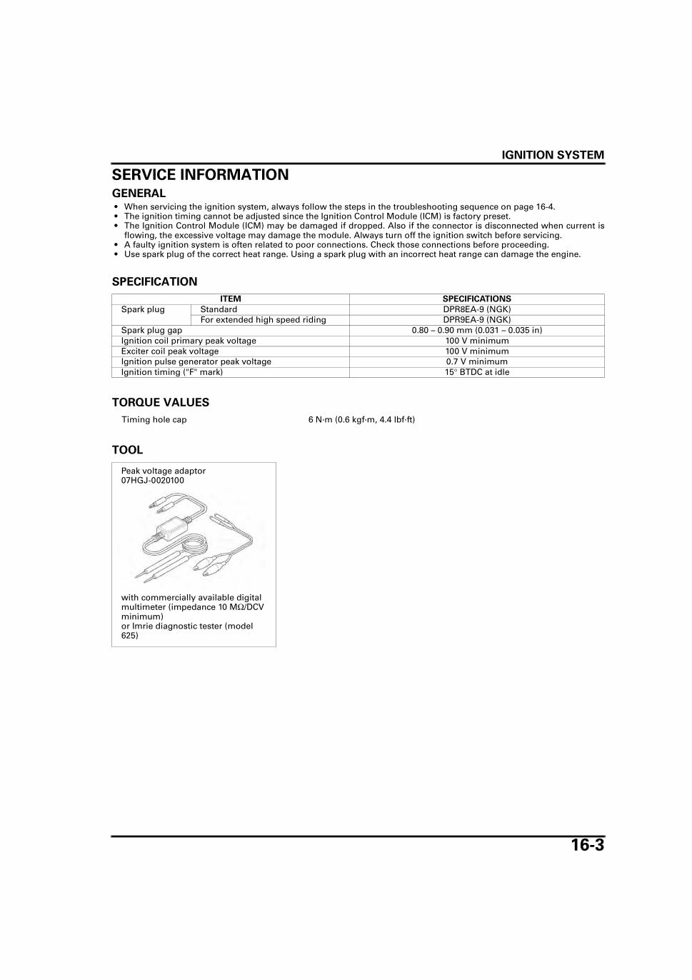
IGNITION SYSTEM
16-3
SERVICE INFORMATIONGENERAL • When servicing the ignition system, always follow the steps in the troubleshooting sequence on page 16-4. • The ignition timing cannot be adjusted since the Ignition Control Module (ICM) is factory preset. • The Ignition Control Module (ICM) may be damaged if dropped. Also if the connector is disconnected when current is
flowing, the excessive voltage may damage the module. Always turn off the ignition switch before servicing. • A faulty ignition system is often related to poor connections. Check those connections before proceeding. • Use spark plug of the correct heat range. Using a spark plug with an incorrect heat range can damage the engine.
SPECIFICATION
TORQUE VALUES
TOOL
ITEM SPECIFICATIONS
Spark plug Standard DPR8EA-9 (NGK)For extended high speed riding DPR9EA-9 (NGK)
Spark plug gap 0.80 – 0.90 mm (0.031 – 0.035 in)Ignition coil primary peak voltage 100 V minimumExciter coil peak voltage 100 V minimumIgnition pulse generator peak voltage 0.7 V minimumIgnition timing ("F" mark) 15° BTDC at idle
Timing hole cap 6 N·m (0.6 kgf·m, 4.4 lbf·ft)
Peak voltage adaptor07HGJ-0020100
with commercially available digital multimeter (impedance 10 MΩ/DCV minimum)or Imrie diagnostic tester (model 625)
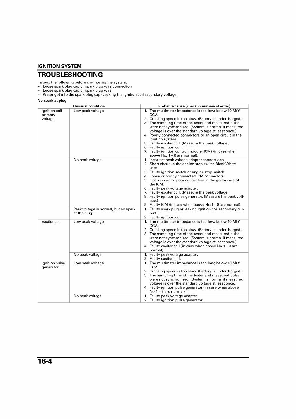
IGNITION SYSTEM
16-4
TROUBLESHOOTINGInspect the following before diagnosing the system.– Loose spark plug cap or spark plug wire connection– Loose spark plug cap or spark plug wire– Water got into the spark plug cap (Leaking the ignition coil secondary voltage)
No spark at plug
Unusual condition Probable cause (check in numerical order)
Ignition coil primary voltage
Low peak voltage. 1. The multimeter impedance is too low; below 10 MΩ/DCV.
2. Cranking speed is too slow. (Battery is undercharged.)3. The sampling time of the tester and measured pulse
were not synchronized. (System is normal if measured voltage is over the standard voltage at least once.)
4. Poorly connected connectors or an open circuit in the ignition system.
5. Faulty exciter coil. (Measure the peak voltage.)6. Faulty ignition coil.7. Faulty ignition control module (ICM) (in case when
above No. 1 – 6 are normal).No peak voltage. 1. Incorrect peak voltage adapter connections.
2. Short circuit in the engine stop switch Black/White wire.
3. Faulty ignition switch or engine stop switch.4. Loose or poorly connected ICM connectors.5. Open circuit or poor connection in the green wire of
the ICM.6. Faulty peak voltage adapter.7. Faulty exciter coil. (Measure the peak voltage.)8. Faulty ignition pulse generator. (Measure the peak volt-
age.)9. Faulty ICM (in case when above No.1 – 8 are normal).
Peak voltage is normal, but no spark at the plug.
1. Faulty spark plug or leaking ignition coil secondary cur-rent.
2. Faulty ignition coil.Exciter coil Low peak voltage. 1. The multimeter impedance is too low; below 10 MΩ/
DCV.2. Cranking speed is too slow. (Battery is undercharged.)3. The sampling time of the tester and measured pulse
were not synchronized. (System is normal if measured voltage is over the standard voltage at least once.)
4. Faulty exciter coil (in case when above No.1 – 3 are normal).
No peak voltage. 1. Faulty peak voltage adapter.2. Faulty exciter coil.
Ignition pulse generator
Low peak voltage. 1. The multimeter impedance is too low; below 10 MΩ/DCV.
2. Cranking speed is too slow. (Battery is undercharged.)3. The sampling time of the tester and measured pulse
were not synchronized. (System is normal if measured voltage is over the standard voltage at least once.)
4. Faulty ignition pulse generator (in case when above No.1 – 3 are normal).
No peak voltage. 1. Faulty peak voltage adapter.2. Faulty ignition pulse generator.

IGNITION SYSTEM
16-5
IGNITION SYSTEM INSPECTION • If there is no spark at the plug, check all connec-
tions for loose or poor contact before measuringthe peak voltage.
• Use a commercially available digital multimeterwith an impedance of 10 MΩ/DCV minimum.
• The display value differs depending upon theinternal impedance of the multimeter.
• If using the Imrie diagnostic tester (model 625),follow the manufacturer’s instructions.
Connect the peak voltage adaptor to the digitalmultimeter, or use the Imrie diagnostic tester.
IGNITION COIL PRIMARY PEAK VOLTAGE • Check all system connections before this inspec-
tion. Poor connected connectors can cause incor-rect readings.
• Check the cylinder compression and check thatthe spark plug is installed correctly in the cylin-der head.
Remove the fuel tank (page 2-4).
Disconnect the spark plug cap from the spark plug.Connect a known good spark plug to the spark plugcap and ground it to the cylinder head as done in aspark test.
TOOL:
Imrie diagnostic tester (model 625) or
Peak voltage adaptor 07HGJ-0020100
with commercially available digital multimeter (impedance 10 MΩ/DCV minimum)
PEAK VOLTAGE ADAPTOR
DIGITAL MULTIMETER
KNOWN GOOD SPARK PLUG

IGNITION SYSTEM
16-6
With the ignition coil primary wire connected, con-nect the peak voltage tester or adaptor probes to theignition coil primary Black/Yellow wire terminal andbody ground.
Shift the transmission into neutral.Turn the engine stop switch to "RUN" and ignitionswitch to "ON".
Crank the engine with the starter motor and readignition coil primary peak voltage.
If the peak voltage is lower than the standard value,follow the checks described in the troubleshootingchart (page 16-4).
EXCITER COIL PEAK VOLTAGE • Check the cylinder compression and check that
the spark plug is installed correctly in the cylin-der head.
Remove the right side cover (page 2-3).
Disconnect the ICM 3P and 4P connectors.Connect the peak voltage tester or adaptor probesto the exciter coil wire terminal of the ICM 3P con-nector from the wire harness side and body ground.
Shift the transmission into neutral.Turn the engine stop switch to "RUN" and ignitionswitch to "ON".Crank the engine with the starter motor and readexciter coil peak voltage.
If the peak voltage measured at the ICM connector isabnormal, measure the peak voltage at the excitercoil wire connector.
TOOL:
Imrie diagnostic tester (model 625) or
Peak voltage adaptor 07HGJ-0020100
with commercially available digital multimeter (impedance 10 MΩ/DCV minimum)
CONNECTION:
Black/Yellow wire terminal (–) – Body ground (+)
PEAK VOLTAGE: 100 V minimum
IGNITION COIL WIRE
PEAK VOLTAGE ADAPTOR
(–) PROBE
(+) PROBE
TOOL:
Imrie diagnostic tester (model 625) or
Peak voltage adaptor 07HGJ-0020100
with commercially available digital multimeter (impedance 10 MΩ/DCV minimum)
CONNECTION:
Black/Red wire terminal (+) – Body ground (–)
PEAK VOLTAGE: 100 V minimum
PEAK VOLTAGE ADAPTOR
ICMICM 3P CONNECTOR
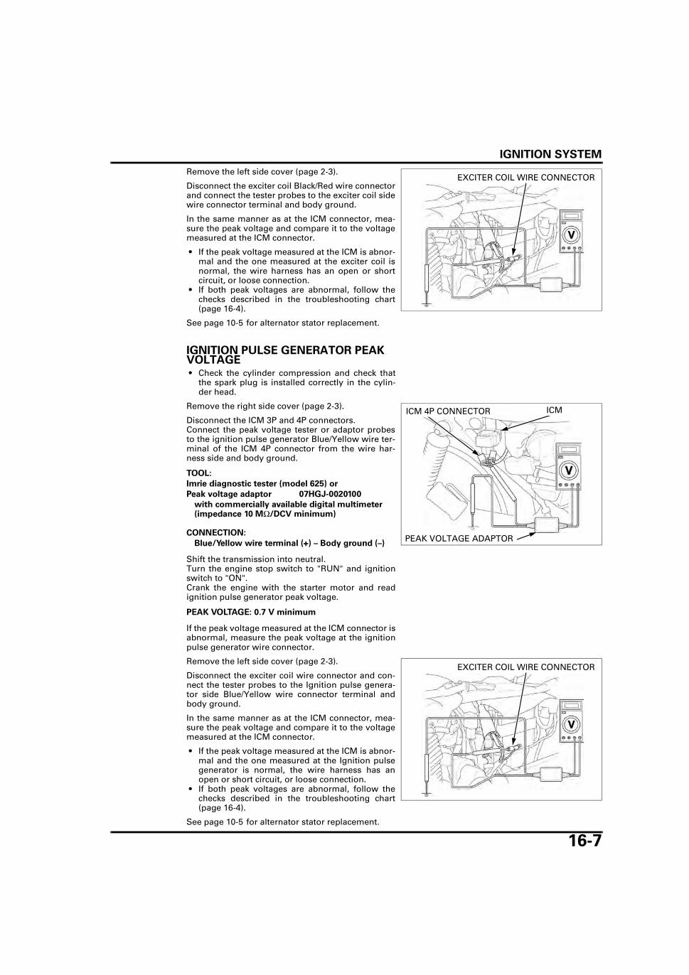
IGNITION SYSTEM
16-7
Remove the left side cover (page 2-3).
Disconnect the exciter coil Black/Red wire connectorand connect the tester probes to the exciter coil sidewire connector terminal and body ground.
In the same manner as at the ICM connector, mea-sure the peak voltage and compare it to the voltagemeasured at the ICM connector.
• If the peak voltage measured at the ICM is abnor-mal and the one measured at the exciter coil isnormal, the wire harness has an open or shortcircuit, or loose connection.
• If both peak voltages are abnormal, follow thechecks described in the troubleshooting chart(page 16-4).
See page 10-5 for alternator stator replacement.
IGNITION PULSE GENERATOR PEAK VOLTAGE • Check the cylinder compression and check that
the spark plug is installed correctly in the cylin-der head.
Remove the right side cover (page 2-3).
Disconnect the ICM 3P and 4P connectors.Connect the peak voltage tester or adaptor probesto the ignition pulse generator Blue/Yellow wire ter-minal of the ICM 4P connector from the wire har-ness side and body ground.
Shift the transmission into neutral.Turn the engine stop switch to "RUN" and ignitionswitch to "ON".Crank the engine with the starter motor and readignition pulse generator peak voltage.
If the peak voltage measured at the ICM connector isabnormal, measure the peak voltage at the ignitionpulse generator wire connector.
Remove the left side cover (page 2-3).
Disconnect the exciter coil wire connector and con-nect the tester probes to the Ignition pulse genera-tor side Blue/Yellow wire connector terminal andbody ground.
In the same manner as at the ICM connector, mea-sure the peak voltage and compare it to the voltagemeasured at the ICM connector.
• If the peak voltage measured at the ICM is abnor-mal and the one measured at the Ignition pulsegenerator is normal, the wire harness has anopen or short circuit, or loose connection.
• If both peak voltages are abnormal, follow thechecks described in the troubleshooting chart(page 16-4).
See page 10-5 for alternator stator replacement.
EXCITER COIL WIRE CONNECTOR
TOOL:
Imrie diagnostic tester (model 625) or
Peak voltage adaptor 07HGJ-0020100
with commercially available digital multimeter (impedance 10 MΩ/DCV minimum)
CONNECTION:
Blue/Yellow wire terminal (+) – Body ground (–)
PEAK VOLTAGE: 0.7 V minimum
PEAK VOLTAGE ADAPTOR
ICMICM 4P CONNECTOR
EXCITER COIL WIRE CONNECTOR

IGNITION SYSTEM
16-8
IGNITION TIMINGWarm up the engine.
Stop the engine and remove the timing hole capand O-ring.
Read the instruc-tions for timing light
operation.
Connect a timing light to the spark plug wire.
Start the engine and let it idle.
The ignition timing is correct if the "F" mark on theflywheel aligns with the index notch on the leftcrankcase cover.
Coat a new O-ring with engine oil and install it ontothe timing hole cap.
Install the timing hole cap and tighten it.
TIMING HOLE CAP
O-RING
IDLE SPEED: 1,400 ± 100 min-1 (rpm)
TIMING LIGHT
INDEX NOTCH
"F" MARK
TORQUE: 6 N·m (0.6 kgf·m, 4.4 lbf·ft)
O-RING
TIMING HOLE CAP

IGNITION SYSTEM
16-9
IGNITION COIL
REMOVAL/INSTALLATIONRemove the fuel tank (page 2-4).
Release the wire band and disconnect the primarywire connector from the ignition coil.
Disconnect the spark plug cap from the spark plug.
Remove the screws, ground terminal and ignitioncoil.
Installation is in the reverse order of removal.
PRIMARY WIRE CONNECTOR
WIRE BAND
GROUND TERMINALSCREWS
IGNITION COIL
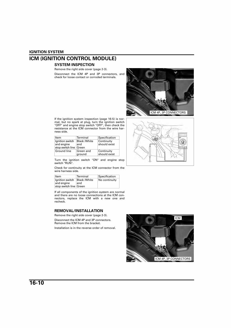
IGNITION SYSTEM
16-10
ICM (IGNITION CONTROL MODULE)SYSTEM INSPECTIONRemove the right side cover (page 2-3).
Disconnect the ICM 4P and 3P connectors, andcheck for loose contact or corroded terminals.
If the ignition system inspection (page 16-5) is nor-mal, but no spark at plug, turn the ignition switch"OFF" and engine stop switch "OFF", then check theresistance at the ICM connector from the wire har-ness side.
Turn the ignition switch "ON" and engine stopswitch "RUN".
Check for continuity at the ICM connector from thewire harness side.
If all components of the ignition system are normaland there are no loose connections at the ICM con-nectors, replace the ICM with a new one andrecheck.
REMOVAL/INSTALLATIONRemove the right side cover (page 2-3).
Disconnect the ICM 4P and 3P connectors.Remove the ICM from the bracket.
Installation is in the reverse order of removal.
ICM 4P, 3P CONNECTORS
Item Terminal SpecificationIgnition switch and engine stop switch line
Black /White andGreen
Continuityshould exist
Ground line Green and ground
Continuityshould exist
Item Terminal SpecificationIgnition switch and engine stop switch line
Black /White andGreen
No continuity
ICM 4P, 3P CONNECTORS
ICM

17-1
17
17. ELECTRIC STARTER
COMPONENT LOCATION ··························· 17-2
SYSTEM DIAGRAM····································· 17-2
SERVICE INFORMATION ···························· 17-3
TROUBLESHOOTING ·································· 17-4
STARTER MOTOR ········································17-6
STARTER RELAY SWITCH·························17-14
NEUTRAL DIODE········································17-15

ELECTRIC STARTER
17-2
ELECTRIC STARTER
COMPONENT LOCATION
SYSTEM DIAGRAM
STARTER MOTOR
IGNITION SWITCH
GEAR POSITION SWITCH
STARTER SWITCH
STARTER RELAY
Bl: Black
Y: Yellow G: Green
R: RedP: Pink
Br: BrownLg: Light green
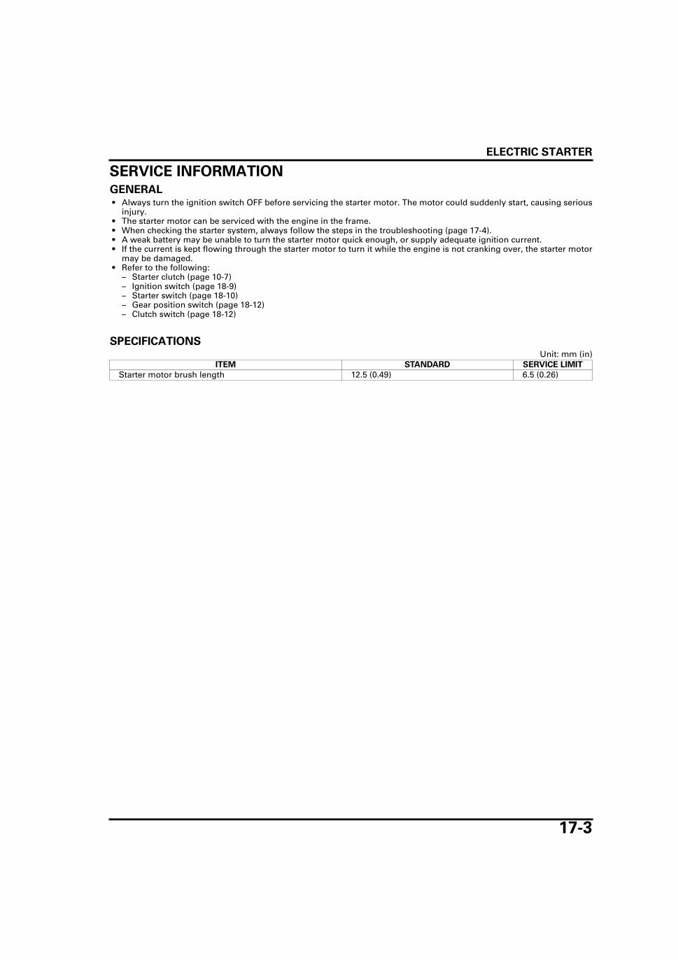
ELECTRIC STARTER
17-3
SERVICE INFORMATIONGENERAL • Always turn the ignition switch OFF before servicing the starter motor. The motor could suddenly start, causing serious
injury. • The starter motor can be serviced with the engine in the frame. • When checking the starter system, always follow the steps in the troubleshooting (page 17-4). • A weak battery may be unable to turn the starter motor quick enough, or supply adequate ignition current. • If the current is kept flowing through the starter motor to turn it while the engine is not cranking over, the starter motor
may be damaged. • Refer to the following:
– Starter clutch (page 10-7)– Ignition switch (page 18-9)– Starter switch (page 18-10)– Gear position switch (page 18-12)– Clutch switch (page 18-12)
SPECIFICATIONSUnit: mm (in)
ITEM STANDARD SERVICE LIMIT
Starter motor brush length 12.5 (0.49) 6.5 (0.26)

ELECTRIC STARTER
17-4
TROUBLESHOOTINGNOTE:
• The starter motor should operate when the transmission is in neutral or when the clutch lever issqueezed.
• Make sure the engine stop switch is turned to " " before starting the engine. The starter motor doesnot operate with the engine stop switch turned to " ".
Starter motor does not turn
1. Fuse Inspection
Check for blown fuse.
Is the fuse blown?
YES – Replace the fuse.
NO – GO TO STEP 2.
2. Battery Inspection
Make sure the battery is fully charged and in good condition.
Is the battery in good condition?
YES – GO TO STEP 3.
NO – Charge or replace the battery (page 15-8).
3. Battery Cable Inspection
Check the battery cables for loose or poorly connected terminal, and for an open circuit.
Is the terminal loose or poorly connected?
YES – • Loose or poorly connected battery cables. • Open circuit in the battery cable.
NO – GO TO STEP 4.
4. Starter Motor Cable Inspection
Check the starter motor cable for loose or poorly connected terminal, and for an open circuit.
Is the terminal loose or poorly connected?
YES – • Loose or poorly connected starter motor cable. • Open circuit in the starter motor cable.
NO – GO TO STEP 5.
5. Starter Relay Switch Operation Inspection
Check the operation of the starter relay switch (page 17-14).
Does the starter relay switch click?
YES – GO TO STEP 6.
NO – GO TO STEP 7.
6. Starter Motor Inspection
Connect the starter motor terminal to the battery positive terminal directly. (A large amount of cur-rent flows, so do not use a thin wire.)
Does the starter motor turn?
YES – Faulty starter relay switch.
NO – Faulty starter motor.
7. Relay Coil Ground Line Inspection
Check the ground line of the starter relay switch (page 17-14).
Is the ground line normal?
YES – GO TO STEP 8.
NO – • Faulty gear position switch (page 18-12). • Faulty neutral diode (page 17-15). • Faulty clutch switch (page 18-12). • Loose or poor contact of the related connector terminal. • Open circuit in the wire harness.
ELECTRIC STARTER
17-5
8. Relay Coil Power Input Line Inspection
Check the power input line of the starter relay switch (page 17-14).
Is the power input line normal?
YES – GO TO STEP 9.
NO – • Faulty ignition switch (page 18-9). • Faulty starter switch (page 18-10). • Loose or poor contact of the related connector terminal. • Open circuit in the wire harness.
9. Starter Relay Switch Inspection
Check the function of the starter relay switch (page 17-15).
Does the starter relay switch function properly?
NO – Faulty starter relay switch.
YES – Loose or poor contact of the starter relay switch connector.
Starter motor turns, but the engine turns slowly • Low battery voltage • Poorly connected battery cable • Poorly connected starter motor cable • Faulty starter motor • Poorly connected ground cable terminal
Starter motor turns, but engine does not turn • Starter motor is running backwards
– Case assembled improperly– Terminals connected improperly
• Faulty starter clutch • Damaged or faulty starter gear train
Starter relay switch clicks, but engine does not turn • Crankshaft does not turn due to engine problems

ELECTRIC STARTER
17-6
STARTER MOTORREMOVALSlide the rubber cap off the starter motor terminal,and remove the terminal nut and starter motorcable.
Remove the two mounting bolts, ground cable andthe starter motor from the crankcase.
Remove the O-ring from the starter motor.
DISASSEMBLY/INSPECTIONRemove the starter motor case screws.
TERMINAL NUT
STARTER MOTOR CABLE
RUBBER CAP
BOLTSGROUND CABLE
STARTER MOTOR
O-RING
SCREWS

ELECTRIC STARTER
17-7
Record the locationand number of
shims. The numberof the shims are dif-
ferent individually.
Remove the following:
– Rear cover– Seal ring– Shim(s)
Record the locationand number of
shims. The numberof the shims are dif-
ferent individually.
Remove the following:
– Front cover– Seal ring– Shim(s)
Remove the armature from the starter motor case.
Check the bushing in the rear cover for wear ordamage.
SHIM(S)SEAL RING
REAR COVER
FRONT COVER
SHIM(S)
SEAL RING
ARMATURE
BUSHING

ELECTRIC STARTER
17-8
Check the oil seal and bushing in the front cover fordeterioration, wear or damage.
Do not use emeryor sand paper onthe commutator.
Check the commutator bars of the armature for dis-coloration.
Check for continuity between pairs of commutatorbars.There should be continuity.
Check for continuity between each commutator barand the armature shaft.There should be no continuity.
BUSHING
OIL SEAL
ARMATURE
COMMUTATOR BARS

ELECTRIC STARTER
17-9
Check for continuity between the insulated brushand cable terminal as shown.There should be continuity.
Check for continuity between the insulated brushand motor case as shown.There should be no continuity.
Check for continuity between the (+) and (–) termi-nals of the brush holder.There should be no continuity.
Remove the following:
– Nut– Washer– Insulators
INSULATED BRUSH
CABLE TERMINAL
INSULATED BRUSH
MOTOR CASE
(–) BRUSH HOLDER
(+) BRUSH HOLDER
NUT
INSULATORS
WASHER

ELECTRIC STARTER
17-10
Remove the brush holder assembly from the startermotor case.
Remove the insulated brush/cable terminal from thebrush holder.
Inspect the brush for wear or damage and measurethe brush length.
BRUSH HOLDERMOTOR CASE
INSULATED BRUSH/CABLE TERMINAL
BRUSH HOLDER
SERVICE LIMIT: 6.5 mm (0.26 in)
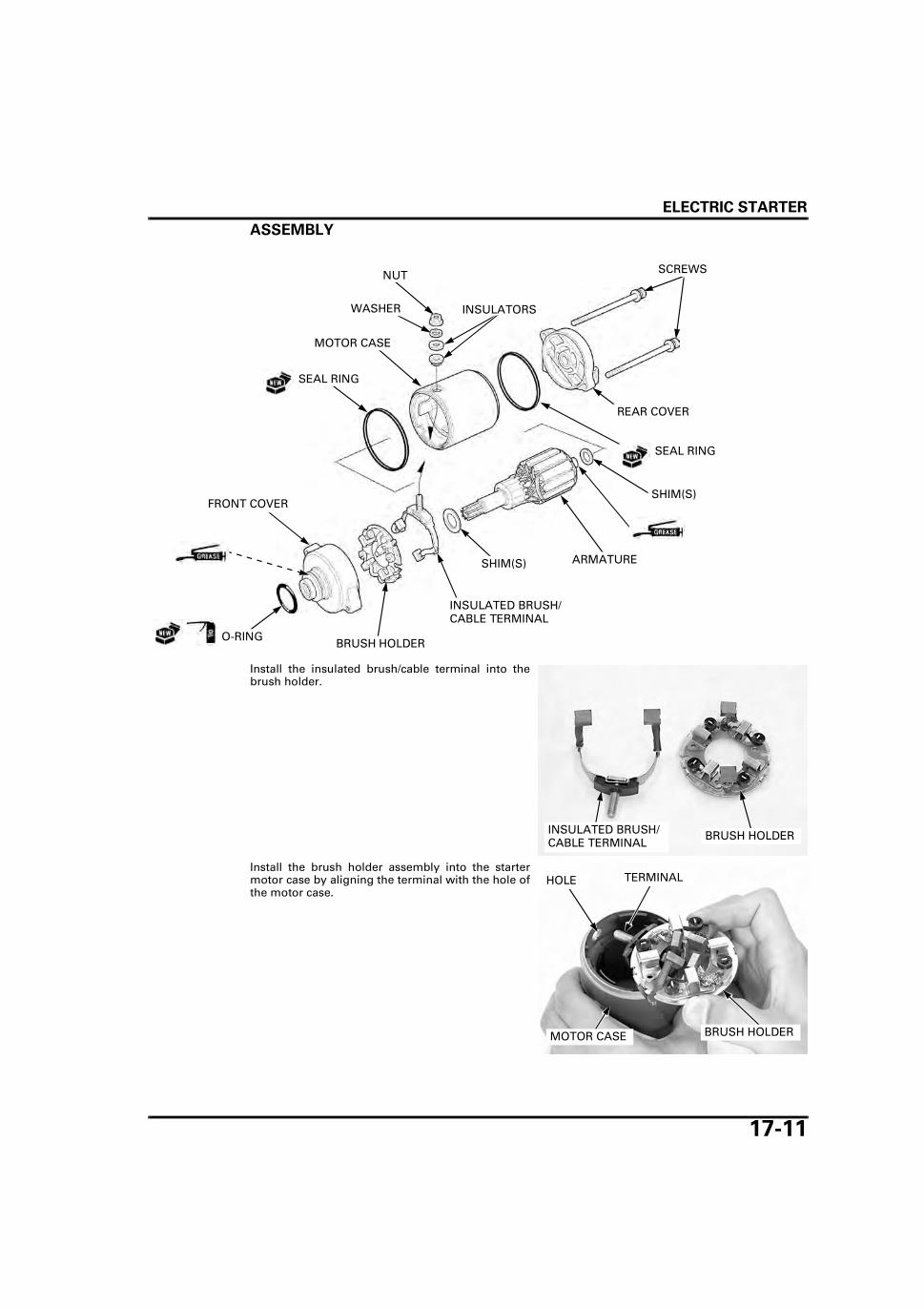
ELECTRIC STARTER
17-11
ASSEMBLY
Install the insulated brush/cable terminal into thebrush holder.
Install the brush holder assembly into the startermotor case by aligning the terminal with the hole ofthe motor case.
FRONT COVER
MOTOR CASE
ARMATURE
BRUSH HOLDER
INSULATORSWASHER
SEAL RING
O-RING
REAR COVER
SEAL RING
SHIM(S)
SHIM(S)
NUT SCREWS
INSULATED BRUSH/CABLE TERMINAL
INSULATED BRUSH/CABLE TERMINAL
BRUSH HOLDER
BRUSH HOLDERMOTOR CASE
TERMINALHOLE

ELECTRIC STARTER
17-12
Align the holder tab with the motor case groove.
Install the following:
– Insulators– Washer– Nut
Install the armature in the motor case.When installing the armature into the motor case,insert the brushes into the brush holder and holdthem, hold the armature tightly to keep the magnetof the case from the pulling the armature.
The coil may be damaged if the magnet pulls thearmature and hits the case.
Install the shimsproperly as noted
during removal.
Install the shim(s) onto the armature shaft.Install a new seal ring onto the motor case.Apply grease to the oil seal lip and bushing in thefront cover.
Install the front cover by aligning the tab on thebrush holder with the groove of the cover.
Align
NUT
INSULATORS
WASHER
ARMATURE
MOTOR CASE
FRONT COVERSHIM(S)
SEAL RING Align
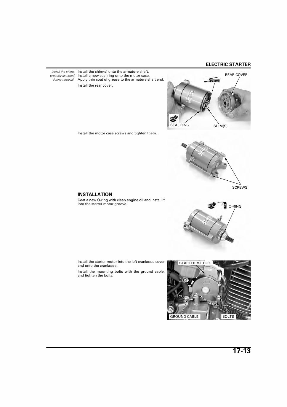
ELECTRIC STARTER
17-13
Install the shimsproperly as noted
during removal.
Install the shim(s) onto the armature shaft.Install a new seal ring onto the motor case.Apply thin coat of grease to the armature shaft end.
Install the rear cover.
Install the motor case screws and tighten them.
INSTALLATIONCoat a new O-ring with clean engine oil and install itinto the starter motor groove.
Install the starter motor into the left crankcase coverand onto the crankcase.
Install the mounting bolts with the ground cable,and tighten the bolts.
SHIM(S)SEAL RING
REAR COVER
SCREWS
O-RING
BOLTSGROUND CABLE
STARTER MOTOR

ELECTRIC STARTER
17-14
Install the starter motor cable and terminal nut ontothe motor terminal and tighten the nut.Install the rubber cap over the motor terminal prop-erly.
STARTER RELAY SWITCH
OPERATION INSPECTIONRemove the left side cover (page 2-3).
Shift the transmission into neutral.Turn the ignition switch to “ON” and push thestarter switch.The coil is normal if the starter relay switch clicks.
If you don't hear the switch click, inspect the relayswitch circuits (page 17-14).
If you hear the switch click, but starter motor doesnot turn, inspect the relay switch (page 17-15).
CIRCUIT INSPECTIONGROUND LINE
Turn the ignition switch to “OFF”.
Disconnect the starter relay switch 2P connector.
Check for continuity between the Green/Red wireterminal of the wire harness side connector andground.
If there is continuity when the transmission is inneutral or when the clutch lever is squeezed, theground circuit is normal.
POWER INPUT LINE
Disconnect the starter relay switch 2P connector.
Turn the ignition switch to “ON”.
Measure the voltage between the Yellow/Red wireterminal (+) and ground (–).
If the battery voltage appears only when the starterswitch is pushed, the circuit is normal.
TERMINAL NUT
STARTER MOTOR CABLE
RUBBER CAP
STARTER RELAY SWITCH
STARTER RELAY SWITCH 2P CONNECTOR
STARTER RELAY SWITCH 2P CONNECTOR
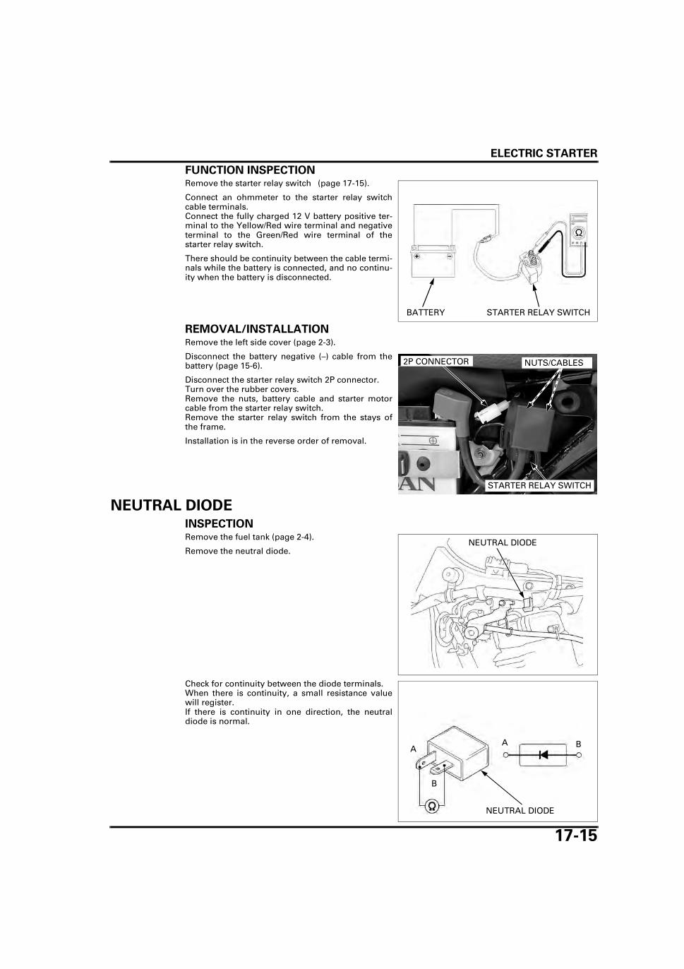
ELECTRIC STARTER
17-15
FUNCTION INSPECTIONRemove the starter relay switch (page 17-15).
Connect an ohmmeter to the starter relay switchcable terminals.Connect the fully charged 12 V battery positive ter-minal to the Yellow/Red wire terminal and negativeterminal to the Green/Red wire terminal of thestarter relay switch.
There should be continuity between the cable termi-nals while the battery is connected, and no continu-ity when the battery is disconnected.
REMOVAL/INSTALLATIONRemove the left side cover (page 2-3).
Disconnect the battery negative (–) cable from thebattery (page 15-6).
Disconnect the starter relay switch 2P connector.Turn over the rubber covers.Remove the nuts, battery cable and starter motorcable from the starter relay switch.Remove the starter relay switch from the stays ofthe frame.
Installation is in the reverse order of removal.
NEUTRAL DIODEINSPECTIONRemove the fuel tank (page 2-4).
Remove the neutral diode.
Check for continuity between the diode terminals.When there is continuity, a small resistance valuewill register.If there is continuity in one direction, the neutraldiode is normal.
STARTER RELAY SWITCHBATTERY
STARTER RELAY SWITCH
NUTS/CABLES2P CONNECTOR
NEUTRAL DIODE
NEUTRAL DIODE
A BA
B

MEMO

18-1
18
18. LIGHTS/METER/SWITCHES
COMPONENT LOCATION ··························· 18-2
SERVICE INFORMATION ···························· 18-3
HEADLIGHT·················································· 18-4
POSITION LIGHT ········································· 18-4
BRAKE/TAIL LIGHT ····································· 18-4
TURN SIGNAL LIGHT·································· 18-5
COMBINATION METER······························· 18-6
TACHOMETER ············································· 18-8
IGNITION SWITCH ·······································18-9
HANDLEBAR SWITCHES ···························18-10
BRAKE LIGHT SWITCHES··························18-11
CLUTCH SWITCH ·······································18-12
GEAR POSITION SWITCH··························18-12
FUEL LEVEL SENSOR ································18-14
HORN ··························································18-15
TURN SIGNAL RELAY ·······························18-16

LIGHTS/METER/SWITCHES
18-2
LIGHTS/METER/SWITCHES
COMPONENT LOCATION
GEAR POSITION SWITCH
RIGHT HANDLEBAR SWITCHES
TURN SIGNAL RELAY
COMBINATION METER
FRONT BRAKE LIGHT SWITCH
REAR BRAKE LIGHT SWITCH
LEFT HANDLEBAR SWITCHES
HORN
CLUTCH SWITCH
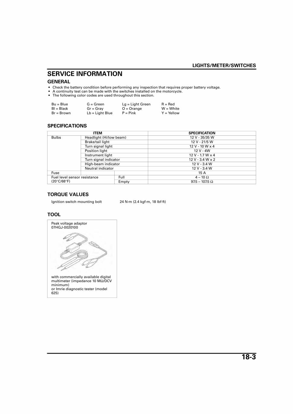
LIGHTS/METER/SWITCHES
18-3
SERVICE INFORMATIONGENERAL • Check the battery condition before performing any inspection that requires proper battery voltage. • A continuity test can be made with the switches installed on the motorcycle. • The following color codes are used throughout this section.
SPECIFICATIONS
TORQUE VALUES
TOOL
Bu = Blue G = Green Lg = Light Green R = RedBl = Black Gr = Gray O = Orange W = WhiteBr = Brown Lb = Light Blue P = Pink Y = Yellow
ITEM SPECIFICATION
Bulbs Headlight (Hi/low beam) 12 V - 35/35 WBrake/tail light 12 V - 21/5 WTurn signal light 12 V - 10 W x 4Position light 12 V - 4WInstrument light 12 V - 1.7 W x 4Turn signal indicator 12 V - 3.4 W x 2High-beam indicator 12 V - 3.4 WNeutral indicator 12 V - 3.4 W
Fuse 15 AFuel level sensor resistance(20°C/68°F)
Full 4 – 10 ΩEmpty 97.5 – 107.5 Ω
Ignition switch mounting bolt 24 N·m (2.4 kgf·m, 18 lbf·ft)
Peak voltage adaptor07HGJ-0020100
with commercially available digital multimeter (impedance 10 MΩ/DCV minimum)or Imrie diagnostic tester (model 625)
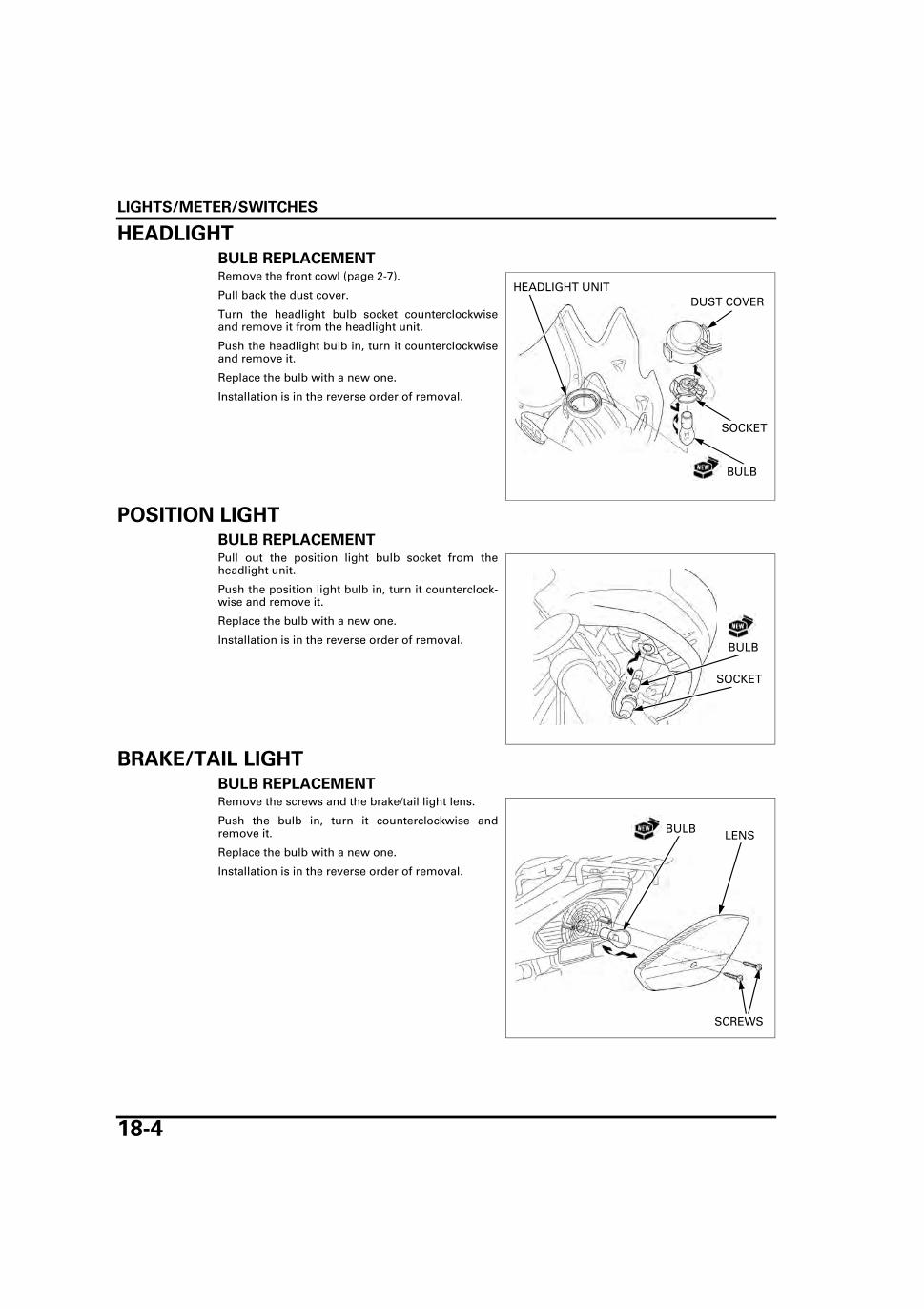
LIGHTS/METER/SWITCHES
18-4
HEADLIGHTBULB REPLACEMENTRemove the front cowl (page 2-7).
Pull back the dust cover.
Turn the headlight bulb socket counterclockwiseand remove it from the headlight unit.
Push the headlight bulb in, turn it counterclockwiseand remove it.
Replace the bulb with a new one.
Installation is in the reverse order of removal.
POSITION LIGHTBULB REPLACEMENTPull out the position light bulb socket from theheadlight unit.
Push the position light bulb in, turn it counterclock-wise and remove it.
Replace the bulb with a new one.
Installation is in the reverse order of removal.
BRAKE/TAIL LIGHTBULB REPLACEMENTRemove the screws and the brake/tail light lens.
Push the bulb in, turn it counterclockwise andremove it.
Replace the bulb with a new one.
Installation is in the reverse order of removal.
DUST COVER
BULB
SOCKET
HEADLIGHT UNIT
SOCKET
BULB
SCREWS
LENSBULB
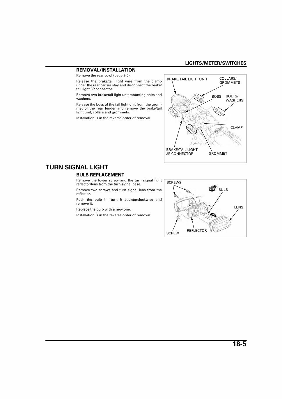
LIGHTS/METER/SWITCHES
18-5
REMOVAL/INSTALLATIONRemove the rear cowl (page 2-5).
Release the brake/tail light wire from the clampunder the rear carrier stay and disconnect the brake/tail light 3P connector.
Remove two brake/tail light unit mounting bolts andwashers.
Release the boss of the tail light unit from the grom-met of the rear fender and remove the brake/taillight unit, collars and grommets.
Installation is in the reverse order of removal.
TURN SIGNAL LIGHT
BULB REPLACEMENTRemove the lower screw and the turn signal lightreflector/lens from the turn signal base.
Remove two screws and turn signal lens from thereflector.
Push the bulb in, turn it counterclockwise andremove it.
Replace the bulb with a new one.
Installation is in the reverse order of removal.
BRAKE/TAIL LIGHT 3P CONNECTOR
BOLTS/WASHERS
BRAKE/TAIL LIGHT UNIT
CLAMP
BOSS
GROMMET
COLLARS/GROMMETS
SCREW
LENS
BULB
REFLECTOR
SCREWS

LIGHTS/METER/SWITCHES
18-6
COMBINATION METERBULB REPLACEMENTRemove the following:
– Combination meter (page 18-6)– Combination meter mounting bracket (page 18-
7)
Pull out the combination meter light bulb sockets.
Replace the bulbs with new ones.
Installation is in the reverse order of removal.
REMOVAL/INSTALLATIONRemove the front cowl (page 2-7).
Release the combination meter connector dustcover from the clamps.
Disconnect the gear position indicator 6P Brownconnector, combination meter 6P Black connectorand combination meter Black/Yellow, Black, Lightblue and Green wire connectors.
Disconnect the speedometer cable.
Remove two combination meter bolts and the com-bination meter.
Installation is in the reverse order of removal.
BULB SOCKETS
BULB
CLAMPS
COVER
GEAR POSITION INDICATOR 6P BROWN CONNECTOR
METER 6P BLACK CONNECTOR
METER WIRE CONNECTORS
SPEEDOMETER CABLEBOLTS

LIGHTS/METER/SWITCHES
18-7
DISASSEMBLY/ASSEMBLYRemove the combination meter (page 18-6).
Remove three screws and the combination meterlower cover.
Remove three nuts/washers and the combinationmeter mounting bracket.
Pull out the combination meter light bulb sockets.
Remove three fuel unit terminal screws and discon-nect the fuel unit terminals.
Remove seven screws and the combination meterupper case from the combination meter unit.
Remove two speedometer mounting screws and thespeedometer unit from the combination meter case. Remove two tachometer mounting screws, washersand the tachometer unit from the combinationmeter case.
SCREWS
LOWER COVER
NUTS/WASHERS
BRACKET
BULB SOCKETS
TERMINAL SCREWS
Do not touch thespeedometer andtachometer panel
surfaces.
SCREWSUPPER CASE
SPEEDOMETER MOUNTING SCREWS
TACHOMETER MOUNTING SCREWS/WASHERS
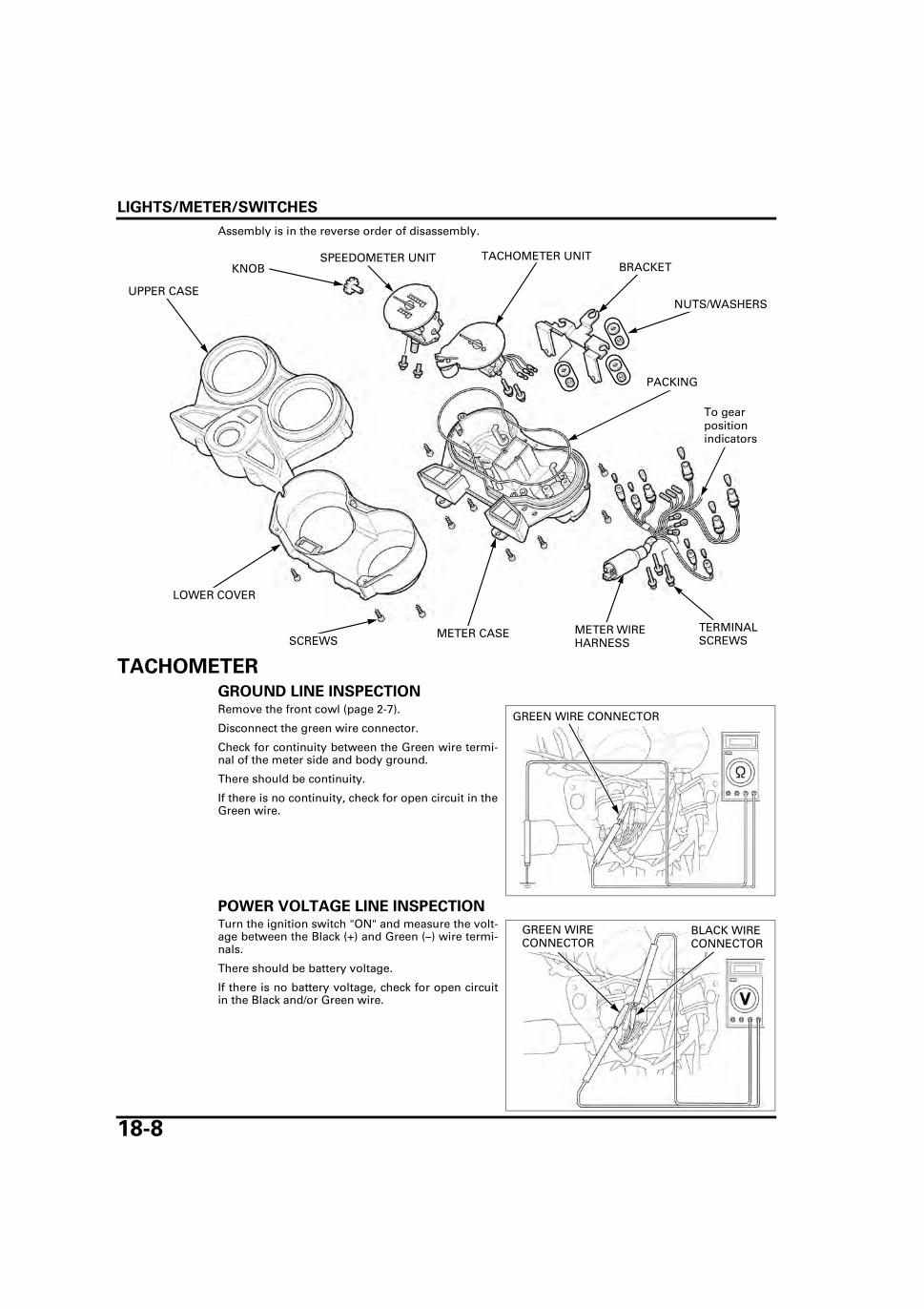
LIGHTS/METER/SWITCHES
18-8
Assembly is in the reverse order of disassembly.
TACHOMETER
GROUND LINE INSPECTIONRemove the front cowl (page 2-7).
Disconnect the green wire connector.
Check for continuity between the Green wire termi-nal of the meter side and body ground.
There should be continuity.
If there is no continuity, check for open circuit in theGreen wire.
POWER VOLTAGE LINE INSPECTIONTurn the ignition switch "ON" and measure the volt-age between the Black (+) and Green (–) wire termi-nals.
There should be battery voltage.
If there is no battery voltage, check for open circuitin the Black and/or Green wire.
KNOBTACHOMETER UNITSPEEDOMETER UNIT
UPPER CASE
LOWER COVER
BRACKET
METER WIRE HARNESSSCREWS
PACKING
METER CASE
To gear position indicators
NUTS/WASHERS
TERMINAL SCREWS
GREEN WIRE CONNECTOR
GREEN WIRE CONNECTOR
BLACK WIRE CONNECTOR
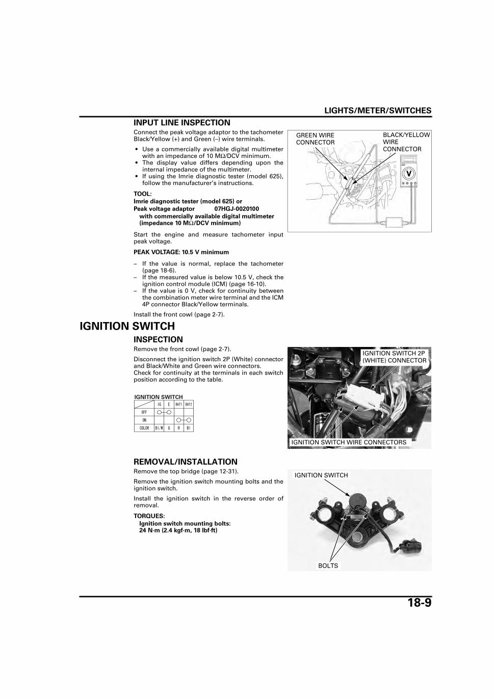
LIGHTS/METER/SWITCHES
18-9
INPUT LINE INSPECTIONConnect the peak voltage adaptor to the tachometerBlack/Yellow (+) and Green (–) wire terminals.
• Use a commercially available digital multimeterwith an impedance of 10 MΩ/DCV minimum.
• The display value differs depending upon theinternal impedance of the multimeter.
• If using the Imrie diagnostic tester (model 625),follow the manufacturer’s instructions.
Start the engine and measure tachometer inputpeak voltage.
– If the value is normal, replace the tachometer(page 18-6).
– If the measured value is below 10.5 V, check theignition control module (ICM) (page 16-10).
– If the value is 0 V, check for continuity betweenthe combination meter wire terminal and the ICM4P connector Black/Yellow terminals.
Install the front cowl (page 2-7).
IGNITION SWITCH
INSPECTIONRemove the front cowl (page 2-7).
Disconnect the ignition switch 2P (White) connectorand Black/White and Green wire connectors.Check for continuity at the terminals in each switchposition according to the table.
REMOVAL/INSTALLATIONRemove the top bridge (page 12-31).
Remove the ignition switch mounting bolts and theignition switch.
Install the ignition switch in the reverse order ofremoval.
TOOL:
Imrie diagnostic tester (model 625) or
Peak voltage adaptor 07HGJ-0020100
with commercially available digital multimeter (impedance 10 MΩ/DCV minimum)
PEAK VOLTAGE: 10.5 V minimum
GREEN WIRE CONNECTOR
BLACK/YELLOW WIRE CONNECTOR
IGNITION SWITCH 2P (WHITE) CONNECTOR
IGNITION SWITCH WIRE CONNECTORS
TORQUES:
Ignition switch mounting bolts: 24 N·m (2.4 kgf·m, 18 lbf·ft)
BOLTS
IGNITION SWITCH
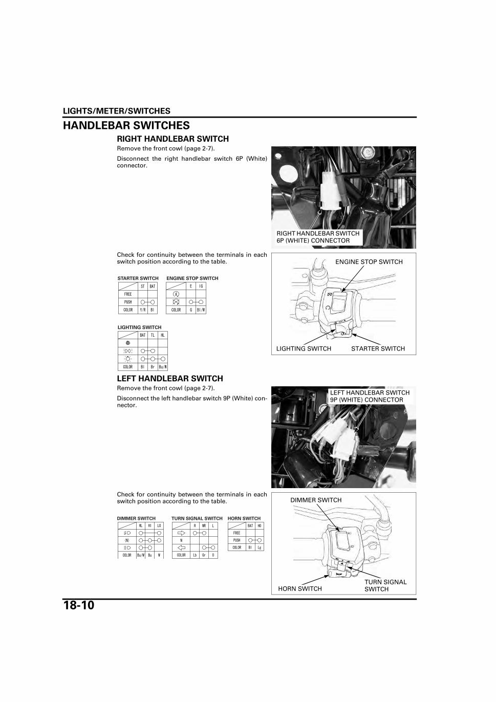
LIGHTS/METER/SWITCHES
18-10
HANDLEBAR SWITCHES
RIGHT HANDLEBAR SWITCHRemove the front cowl (page 2-7).
Disconnect the right handlebar switch 6P (White)connector.
Check for continuity between the terminals in eachswitch position according to the table.
LEFT HANDLEBAR SWITCHRemove the front cowl (page 2-7).
Disconnect the left handlebar switch 9P (White) con-nector.
Check for continuity between the terminals in eachswitch position according to the table.
3P (BLACK) CONNECTORRIGHT HANDLEBAR SWITCH 6P (WHITE) CONNECTOR
STARTER SWITCHLIGHTING SWITCH
ENGINE STOP SWITCH
LEFT HANDLEBAR SWITCH 9P (WHITE) CONNECTOR
TURN SIGNAL SWITCHHORN SWITCH
DIMMER SWITCH
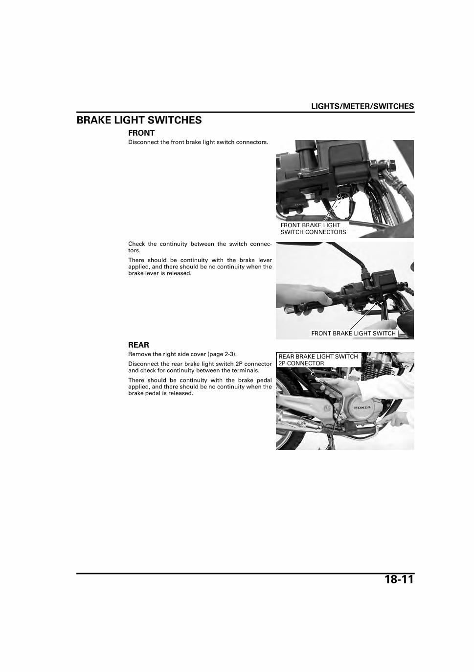
LIGHTS/METER/SWITCHES
18-11
BRAKE LIGHT SWITCHES
FRONTDisconnect the front brake light switch connectors.
Check the continuity between the switch connec-tors.
There should be continuity with the brake leverapplied, and there should be no continuity when thebrake lever is released.
REAR Remove the right side cover (page 2-3).
Disconnect the rear brake light switch 2P connectorand check for continuity between the terminals.
There should be continuity with the brake pedalapplied, and there should be no continuity when thebrake pedal is released.
FRONT BRAKE LIGHT SWITCH CONNECTORS
FRONT BRAKE LIGHT SWITCH
REAR BRAKE LIGHT SWITCH 2P CONNECTOR

LIGHTS/METER/SWITCHES
18-12
CLUTCH SWITCH
INSPECTIONDisconnect the clutch switch connectors.
There should be continuity with the clutch leverapplied, and there should be no continuity when theclutch lever is released.
GEAR POSITION SWITCH
INSPECTIONRemove the left side cover (page 2-3).
Disconnect the gear position switch 6P connector.
Check for continuity between the terminals at eachgear position.
GEAR POSITION SWITCH
CLUTCH SWITCH CONNECTORS
CLUTCH SWITCH
GEAR POSITION SWITCH 6P CONNECTOR
GEAR POSITION SWITCH 6P CONNECTOR

LIGHTS/METER/SWITCHES
18-13
REMOVALRemove the left crankcase rear cover (page 6-4).Disconnect the gear position switch 6P connector(page 18-12).
Remove the bolt and the alternator/gear positionswitch wire guide plate.
Release the gear position switch wire from theclamp.
Remove the gear position switch mounting bolt andthe gear position switch.
Check the condition of the spring pin.
INSTALLATIONInstall the gear position switch while aligning thespring pin with the slot of the shift drum.
BOLT
GUIDE PLATE
CLAMP
BOLT
GEAR POSITION SWITCH
DRIVE PIECE SPRING
SPRING PIN
DRIVE PIECE SPRINGSPRING PIN
SLOT
GEAR POSITION SWITCH

LIGHTS/METER/SWITCHES
18-14
Install and tighten the gear position switch mount-ing bolt.
Set the gear position switch wire to the clamp androute it in the left crankcase cover groove properly.
Install the alternator/gear position switch wire guideplate and tighten the bolt.
Connect the gear position switch 6P connector.Install the left crankcase rear cover (page 6-5).
FUEL LEVEL SENSOR
INSPECTIONRemove the fuel level sensor (page 18-14).
Connect the ohmmeter to the fuel level sensor ter-minals.Inspect the resistance of the float at the top and bot-tom positions.
REMOVAL/INSTALLATIONRemove the fuel tank (page 2-4).
Release the fuel level sensor wire from the wireclamp.Remove four nuts and fuel level sensor unit.
BOLT
BOLT
GUIDE PLATE
CLAMP
FULL EMPTYResistance (20°C/68°F) 4 – 10 Ω 97.5 – 107.5 Ω
FULL
EMPTY
NUTS WIRE CLAMP
FUEL LEVEL SENSOR UNIT
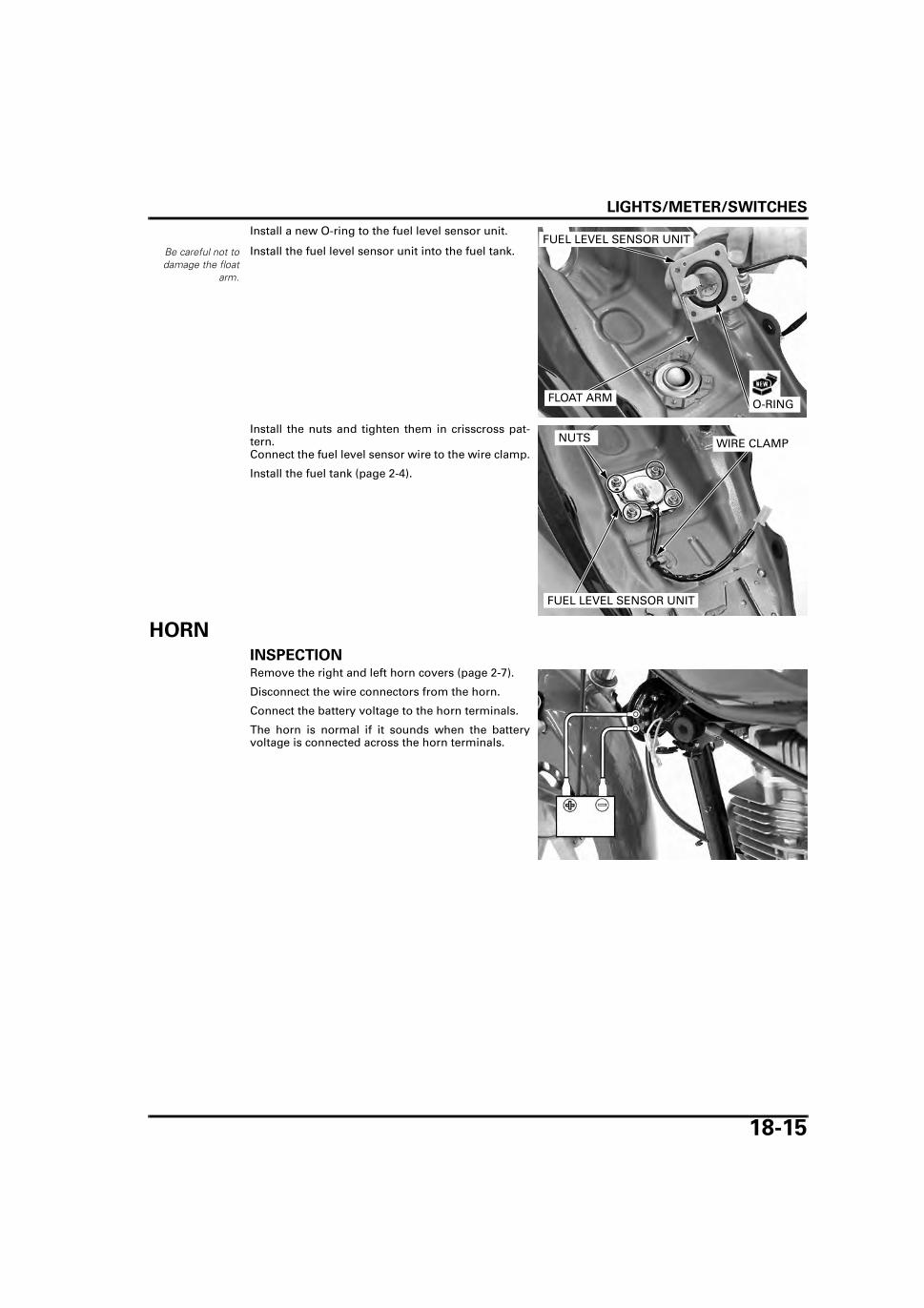
LIGHTS/METER/SWITCHES
18-15
Install a new O-ring to the fuel level sensor unit.
Install the fuel level sensor unit into the fuel tank.
Install the nuts and tighten them in crisscross pat-tern.Connect the fuel level sensor wire to the wire clamp.
Install the fuel tank (page 2-4).
HORN
INSPECTIONRemove the right and left horn covers (page 2-7).
Disconnect the wire connectors from the horn.
Connect the battery voltage to the horn terminals.
The horn is normal if it sounds when the batteryvoltage is connected across the horn terminals.
Be careful not todamage the float
arm.
O-RINGFLOAT ARM
FUEL LEVEL SENSOR UNIT
NUTS WIRE CLAMP
FUEL LEVEL SENSOR UNIT

LIGHTS/METER/SWITCHES
18-16
TURN SIGNAL RELAY INSPECTION1. Recommended Inspection
Check the following – Battery condition– Burned out bulb or non-specified wattage– Burned fuse– Ignition switch and turn signal switch func-
tion– Loose connector
Are the above items in good condition?
NO – Replace or repair the malfunctionpart(s)
YES – GO TO STEP 2.
2. Turn Signal Circuit Inspection
Remove the left side cover (page 2-3).Disconnect the turn signal relay 2P connectorfrom the relay.Short the turn signal relay connector with ajumper wire. Turn the ignition switch on andcheck the turn signal light by turning the switch"ON".
Does the light come on?
YES – • Faulty turn signal relay • Poor connection of the connector.
NO – Open or short circuit in wire harness
REMOVAL/INSTALLATIONRemove the left side cover (page 2-3).
Disconnect the turn signal relay 2P connector andremove the turn signal relay from the stay.
Installation is in the reverse order of removal.
TURN SIGNAL RELAY 2P CONNECTOR
TURN SIGNAL RELAY
TURN SIGNAL RELAY 2P CONNECTOR

19-1
19
19. WIRING DIAGRAM
WIRING DIAGRAM ······································ 19-2

WIRING DIAGRAM
19-2
WIRING DIAGRAM
WIRING DIAGRAM

20-1
20
20. TROUBLESHOOTING
ENGINE DOES NOT START OR IS HARD TO START ·························································· 20-2
ENGINE LACKS POWER ····························· 20-3
POOR PERFORMANCE AT LOW AND IDLE SPEED ···························································20-5
POOR PERFORMANCE AT HIGH SPEED ····20-6
POOR HANDLING·········································20-6

TROUBLESHOOTING
20-2
TROUBLESHOOTING
ENGINE DOES NOT START OR IS HARD TO START1. Fuel Line Inspection
Check fuel flow to the carburetor.
Does fuel reach the carburetor?
NO – • Clogged fuel hose or fuel strainer • Clogged fuel valve • Clogged fuel cap breather • Sticking float valve
YES – GO TO STEP 2.
2. Spark Plug Inspection
Remove and inspect the spark plug.
Is the spark plug wet?
YES – • Flooded carburetor • Throttle valve open • Dirty air cleaner • Improperly adjusted pilot screw
NO – GO TO STEP 3.
3. Spark Test
Perform spark test.
Is there weak or no spark?
YES – • Faulty spark plug • Fouled spark plug • Loose or disconnected ignition system wires • Broken or shorted spark plug wire • Broken or shorted ignition coil • Faulty exciter coil • Faulty igniting pulse generator • Faulty ignition switch • Faulty engine stop switch • Faulty ignition control module (ICM)
NO – GO TO STEP 4.
4. Engine Starting Condition
Start engine by following normal procedure.
Does the engine start then stops?
YES – • Improper choke operation • Incorrectly adjusted carburetor • Leaking carburetor insulator • Improper ignition timing (Faulty ICM or ignition pulse generator) • Contaminated fuel
NO – GO TO STEP 5.
5. Cylinder Compression
Test cylinder compression.
Is the compression low?
YES – • Valve clearance too small • Valve stuck open • Worn cylinder and piston rings • Damaged cylinder head gasket • Seized valve • Improper valve timing

TROUBLESHOOTING
20-3
ENGINE LACKS POWER1. Drive Train Inspection
Raise the rear wheel off the ground and spin it by hand.
Does the wheel spin freely?
NO – • Brake dragging • Worn or damaged wheel bearings • Bent axle • Drive chain too tight
YES – GO TO STEP 2.
2. Tire Pressure Inspection
Check tire pressure.
Is the tire pressure low?
YES – • Faulty tire valve • Punctured tire
NO – GO TO STEP 3.
3. Clutch Inspection
Accelerate rapidly from low to second.
Does the engine speed change accordingly when the clutch is engaged?
NO – • Clutch slipping • Worn clutch discs/plates • Warped clutch discs/plates • Weak clutch spring • Sticking clutch lifter • Additive in engine oil
YES – GO TO STEP 4.
4. Engine Condition Inspection
Accelerate lightly.
Does the engine speed increase?
NO – • Fuel/air mixture too rich or lean • Clogged air cleaner • Restricted fuel flow • Clogged muffler • Clogged fuel cap breather • Carburetor choke is on • Excessive carbon build-up in combustion chamber
YES – GO TO STEP 5.
5. Engine Condition Inspection
Accelerate or run at high speed.
Is there knocking?
YES – • Worn piston and cylinder • Use of poor quality fuel • Excessive carbon build-up in combustion chamber • Ignition timing too advanced (Faulty ICM) • Lean fuel mixture
NO – GO TO STEP 6.
6. Ignition Timing Inspection
Check ignition timing.
Is the ignition timing correct?
NO – • Faulty ignition control module (ICM) • Faulty ignition pulse generator
YES – GO TO STEP 7.

TROUBLESHOOTING
20-4
7. Engine Oil Inspection
Check the oil level and condition.
Is the oil level correct and the oil in good condition?
NO – • Oil level too high • Oil level too low • Contaminated oil
YES – GO TO STEP 8.
8. Spark Plug Inspection
Remove and inspect the spark plug.
Is the spark plug fouled or discolored?
NO – • Plugs not serviced frequently enough • Incorrect spark plug heat range • Incorrect spark plug gap
YES – GO TO STEP 9.
9. Cylinder compression Inspection
Test the cylinder compression.
Is the compression low?
YES – • Valve clearance too small • Valve stuck open • Worn cylinder and piston rings • Damaged cylinder head gasket • Improper valve timing
NO – GO TO STEP 10.
10. Carburetor Inspection
Check the carburetor for clogs.
Is the carburetor clogged?
YES – • Carburetor not serviced frequently enough • Dirt getting passed the air cleaner
NO – GO TO STEP 11.
11. Lubrication Inspection
Remove cylinder head cover and inspect lubrication.
Is the valve train lubricated properly?
NO – • Faulty oil pump • Clogged oil passage • Clogged oil strainer

TROUBLESHOOTING
20-5
POOR PERFORMANCE AT LOW AND IDLE SPEED1. Pilot Screw Inspection
Check carburetor pilot screw adjustment.
Is the adjustment correct?
NO – See page 5-21
YES – GO TO STEP 2.
2. Intake Air Leak Inspection
Check for leaking carburetor insulator.
Is there leaking?
YES – • Loose carburetor insulator bands • Damaged insulator
NO – GO TO STEP 3.
3. Spark Test
Perform spark test.
Is there weak or intermittent spark?
YES – • Faulty spark plug • Fouled spark plug • Loose or disconnected ignition system wires • Broken or shorted spark plug wire • Faulty ignition coil • Faulty ignition pulse generator • Faulty ignition switch • Faulty engine stop switch • Faulty ignition control module (ICM)
NO – GO TO STEP 4.
4. Ignition Timing Inspection
Check ignition timing.
Is the ignition timing correct?
NO – • Faulty ignition control module (ICM) • Faulty ignition pulse generator

TROUBLESHOOTING
20-6
POOR PERFORMANCE AT HIGH SPEED1. Fuel Line Inspection
Disconnect fuel line at carburetor.
Does fuel flow freely?
NO – • Clogged fuel line • Clogged fuel cap breather • Faulty fuel valve • Clogged fuel strainer
YES – GO TO STEP 2.
2. Carburetor Inspection
Check carburetor for clogs.
Is the carburetor clogged?
YES – • Carburetor not serviced frequently enough • Dirt getting passed the air cleaner
NO – GO TO STEP 3.
3. Ignition Timing Inspection
Check ignition timing.
Is the ignition timing correct?
NO – • Faulty ignition control module (ICM) • Faulty ignition pulse generator
YES – GO TO STEP 4.
4. Valve Timing Inspection
Check valve timing.
Is the valve timing correct?
NO – Cam sprocket not installed properly.
YES – GO TO STEP 5.
5. Valve Spring Inspection
Check valve springs.
Are the valve springs weak?
YES – Faulty valve spring.
POOR HANDLINGSteering is heavy • Steering bearing adjustment nut too tight • Damaged steering head bearings • Low tire pressure
Either wheel is wobbling • Excessive wheel bearing play • Bent rim • Improperly installed wheel hub • Excessively worn swingarm pivot bearings • Bent frame
Motorcycle pulls to one side • Front and rear wheels not aligned • Bent fork • Bent swingarm • Bent axle • Bent frame • Faulty shock absorber

21-1
21
21. INDEXAAIR CLEANER ·································································· 3-6AIR CLEANER HOUSING ················································ 5-5AIR CUT-OFF VALVE····················································· 5-13ALTERNATOR CHARGING COIL ································ 15-11BBATTERY ······································································· 15-6
MAINTENANCE ························································ 3-14BATTERY/CHARGING SYSTEM SPECIFICATIONS······· 1-9BRAKE CALIPER ·························································· 14-15BRAKE FLUID (TYPE II, IV)············································ 3-14BRAKE FLUID REPLACEMENT/AIR BLEEDING ··········· 14-5BRAKE LIGHT SWITCH ················································· 3-18BRAKE LIGHT SWITCHES ·········································· 18-11BRAKE PAD/DISC ·························································· 14-7BRAKE PEDAL/CENTER STAND ································ 13-16BRAKE SHOES WEAR (TYPE I, III) ······························· 3-15BRAKE SHOES/PADS WEAR (TYPE II, IV) ··················· 3-16BRAKE SYSTEM···························································· 3-16BRAKE/TAIL LIGHT ······················································· 18-4CCABLE & HARNESS ROUTING ···································· 1-16CAM FOLLOWER/SHAFT················································ 8-6CAM FOLLOWER/SHAFT INSPECTION ························· 8-6CAMSHAFT······································································ 8-7CARBURETOR ASSEMBLY ·········································· 5-16CARBURETOR BODY CLEANING ································ 5-15CARBURETOR DISASSEMBLY ···································· 5-14CARBURETOR INSTALLATION ···································· 5-19CARBURETOR REMOVAL ············································ 5-10CHARGING SYSTEM INSPECTION······························ 15-9CHOKE LEVER ······························································· 5-11CLUTCH ··········································································· 9-6CLUTCH LIFTER ARM ····················································· 9-6CLUTCH SWITCH ························································ 18-12CLUTCH SYSTEM ························································· 3-18CLUTCH/GEARSHIFT LINKAGE SPECIFICATIONS ······· 1-6COMBINATION METER ················································ 18-6COMPONENT LOCATION
BATTERY/CHARGING SYSTEM ······························ 15-2ELECTRIC STARTER ················································· 17-2IGNITION SYSTEM ··················································· 16-2LIGHTS/METER/SWITCHES ····································· 18-2
CRANKCASE ASSEMBLY··········································· 11-19CRANKCASE SEPARATION ········································· 11-6CRANKSHAFT ······························································· 11-7CRANKSHAFT/TRANSMISSION/KICKSTARTER SPECIFICATIONS ···························································· 1-7CYLINDER ········································································ 8-4CYLINDER COMPRESSION ············································ 7-6CYLINDER HEAD ··························································· 7-12CYLINDER HEAD COVER················································ 7-7CYLINDER HEAD/VALVES SPECIFICATIONS················ 1-5CYLINDER/PISTON SPECIFICATIONS ··························· 1-6DDRIVE CHAIN································································· 3-12DRIVE SPROCKET ··························································· 6-4EELECTRIC STARTER SPECIFICATIONS ························· 1-9EMISSION CONTROL SYSTEMS ································· 1-25ENGINE & FRAME TORQUE VALUES ························· 1-10ENGINE IDLE SPEED····················································· 3-11ENGINE INSTALLATION··············································· 6-10ENGINE OIL ····································································· 3-9ENGINE OIL STRAINER SCREEN································· 3-10ENGINE REMOVAL ························································· 6-6EXHAUST PIPE/MUFFLER ·············································· 2-8FFLYWHEEL INSTALLATION ········································· 10-9FLYWHEEL REMOVAL ·················································· 10-6FOOTPEG BAR ································································ 2-8FORK ············································································ 12-24FRONT COWL ·································································· 2-7FRONT DRUM BRAKE (TYPE I, III) ····························· 12-20FRONT FENDER ······························································ 2-6
FRONT WHEEL (TYPE I, III) ········································· 12-11(TYPE II, IV)······························································ 12-15
FRONT WHEEL/BRAKE/SUSPENSION/STEERING SPECIFICATIONS····························································· 1-8FUEL LEVEL SENSOR ················································· 18-14FUEL LINE ········································································ 3-4FUEL STRAINER ···························································· 5-26FUEL STRAINER SCREEN··············································· 3-4FUEL SYSTEM SPECIFICATIONS··································· 1-5FUEL TANK ······································································ 2-4GGEAR POSITION SWITCH··········································· 18-12GEARSHIFT LINKAGE ··················································· 9-11GENERAL INFORMATION ·············································· 1-2GENERAL SPECIFICATIONS··········································· 1-4HHANDLEBAR ·································································· 12-7HANDLEBAR SWITCHES ············································ 18-10HEADLIGHT ··································································· 18-4HEADLIGHT AIM ··························································· 3-18HORN ··········································································· 18-15HORN COVER ·································································· 2-7HYDRAULIC BRAKE SPECIFICATIONS (TYPE II, IV) ····· 1-8IICM (IGNITION CONTROL MODULE) ························ 16-10IGNITION COIL ······························································ 16-9IGNITION SWITCH ························································ 18-9IGNITION SYSTEM INSPECTION ································· 16-5IGNITION SYSTEM SPECIFICATIONS ··························· 1-9IGNITION TIMING ························································· 16-8INSULATOR ··································································· 5-20KKICKSTARTER ····························································· 11-14LLEFT CRANKCASE COVER INSTALLATION ·············· 10-11LEFT CRANKCASE COVER REMOVAL ························ 10-4LICENSE PLATE HOLDER ··············································· 2-8LIGHTS/METERS/SWITCHES SPECIFICATIONS ··········· 1-9LUBRICATION & SEAL POINTS ··································· 1-14LUBRICATION SYSTEM DIAGRAM ······························· 4-2LUBRICATION SYSTEM SPECIFICATIONS ··················· 1-5MMAINTENANCE SCHEDULE ··········································· 3-3MASTER CYLINDER ···················································· 14-10MODEL IDENTIFICATION ··············································· 1-2NNEUTRAL DIODE ························································· 17-15NUTS, BOLTS, FASTENERS ········································· 3-20OOIL FILTER ROTOR CLEANING ······································ 4-4OIL PUMP········································································· 4-5PPILOT SCREW ADJUSTMENT······································ 5-21PISTON··········································································· 8-10POSITION LIGHT ··························································· 18-4RREAR CARRIER ································································ 2-5REAR COWL····································································· 2-5REAR DRUM BRAKE ··················································· 13-13REAR FENDER ································································· 2-6REAR WHEEL ································································· 13-6REAR WHEEL/SUSPENSION SPECIFICATIONS············ 1-8REGULATOR/RECTIFIER ············································· 15-10RIGHT CRANKCASE COVER INSTALLATION ············· 9-14RIGHT CRANKCASE COVER REMOVAL ························ 9-5ROCKER ARM HOLDER ················································ 7-10SSEAT················································································· 2-4SECONDARY AIR SUPPLY SYSTEM
FUEL SYSTEM ·························································· 5-22MAINTENANCE ························································ 3-11
SERVICE INFORMATIONALTERNATOR/STARTER CLUTCH··························· 10-3BATTERY/CHARGING SYSTEM······························· 15-3CLUTCH/GEARSHIFT LINKAGE ································· 9-3CRANKCASE/TRANSMISSION/CRANKSHAFT······· 11-3CYLINDER HEAD/VALVES·········································· 7-3CYLINDER/PISTON/CAMSHAFT ································ 8-3ELECTRIC STARTER ················································· 17-3ENGINE REMOVAL/INSTALLATION·························· 6-3

INDEX
21-2
FRAME/BODY PANELS/EXHAUST SYSTEM ············ 2-2FRONT WHEEL/BRAKE/SUSPENSION/STEERING · 12-4FUEL SYSTEM ···························································· 5-3HYDRAULIC BRAKE·················································· 14-3IGNITION SYSTEM ··················································· 16-3LIGHTS/METER/SWITCHES ····································· 18-3LUBRICATION SYSTEM ············································· 4-3MAINTENANCE ·························································· 3-2REAR WHEEL/BRAKE/SUSPENSION ······················ 13-3
SERVICE RULES ······························································ 1-2SHOCK ABSORBER····················································· 13-20SIDE COVERS ·································································· 2-3SIDE STAND ·································································· 3-19SPARK PLUG ··································································· 3-7STANDARD TORQUE VALUES ···································· 1-10STARTER CLUTCH ························································ 10-7STARTER MOTOR ························································· 17-6STARTER RELAY SWITCH·········································· 17-14STATOR/IGNITION PULSE GENERATOR ···················· 10-5STEERING HEAD BEARINGS ······································· 3-21STEERING STEM························································· 12-31STORAGE TANK······························································ 5-8SUSPENSION ································································ 3-19SWINGARM ································································· 13-21SYSTEM COMPONENTS
ALTERNATOR/STARTER CLUTCH ·························· 10-2CLUTCH/GEARSHIFT LINKAGE ································· 9-2CRANKCASE/TRANSMISSION/CRANKSHAFT······· 11-2CYLINDER HEAD/VALVES·········································· 7-2CYLINDER/PISTON/CAMSHAFT ································ 8-2ENGINE REMOVAL/INSTALLATION ························· 6-2FRONT WHEEL/BRAKE/SUSPENSION/STEERING · 12-2FUEL SYSTEM ···························································· 5-2HYDRAULIC BRAKE·················································· 14-2REAR WHEEL/BRAKE/SUSPENSION ······················ 13-2
SYSTEM DIAGRAMBATTERY/CHARGING SYSTEM ·······························15-2ELECTRIC STARTER··················································17-2IGNITION SYSTEM ···················································16-2
TTACHOMETER ·······························································18-8THROTTLE OPERATION ··················································3-5THROTTLE VALVE ···························································5-8TRANSMISSION ····························································11-8TROUBLESHOOTING
ALTERNATOR/STARTER CLUTCH ···························10-3BATTERY/CHARGING SYSTEM ·······························15-5CLUTCH/GEARSHIFT LINKAGE ·································9-4CRANKCASE/TRANSMISSION/CRANKSHAFT ·······11-5CYLINDER HEAD/VALVES ··········································7-5CYLINDER/PISTON/CAMSHAFT ································8-3ELECTRIC STARTER··················································17-4ENGINE DOES NOT START OR IS HARD TO START ········································································20-2ENGINE LACKS POWER ···········································20-3FRAME/BODY PANELS/EXHAUST SYSTEM·············2-2FRONT WHEEL/BRAKE/SUSPENSION/STEERING ·12-6FUEL SYSTEM ·····························································5-4HYDRAULIC BRAKE ··················································14-4IGNITION SYSTEM ···················································16-4LUBRICATION SYSTEM ·············································4-3POOR HANDLING ·····················································20-6POOR PERFORMANCE AT HIGH SPEED ·················20-6POOR PERFORMANCE AT LOW AND IDLE SPEED ········································································20-5REAR WHEEL/BRAKE/SUSPENSION ·······················13-5
TURN SIGNAL LIGHT ····················································18-5TURN SIGNAL RELAY ·················································18-16VVALVE CLEARANCE ························································3-8WWHEELS/TIRES ······························································3-20WIRING DIAGRAM ························································19-2