type of exhibit: list of attached exhibits · dual display multimeter protek 506 log periodic...
TRANSCRIPT

1
TYPE OF EXHIBIT: LIST OF ATTACHED EXHIBITS FCC PART: 2.1033(c)(14) MANUFACTURER: RITRON, INC. 505 West Carmel Drive Carmel, IN 46032 MODEL: DTX-142 TYPE OF UNIT: VHF-FM Two Way Radio Transceiver Module FCC ID: AIERIT17-142 DATE: May 30, 2003 Description of Exhibit FCC Rule Section Page List of Test Equipment Used 2.947 (d) 2 Required Measurements Radio Frequency Power Output 2.1046 3 Transmitter Audio Overall Response 2.1047 (a) 4 Transmitter Low-Pass Filter Response 2.1047 (a) 5 Modulation Limiting 2.1047 (b) 6 Emissions Designator Calculations 8 Occupied Bandwidth 2.1049 (c)(1) 9 Spurious Emissions at Antenna Terminals 2.1051 14 Field Strength of Spurious Emissions 2.1053 (b) 15 Frequency Stability vs. Temperature 2.1055 (a)17 Frequency Stability vs. Voltage 2.1055 (d)19 Transient Frequency Behavior 90.214 21

2
TYPE OF EXHIBIT: TEST EQUIPMENT LIST FCC PART: 2.947 (d) MANUFACTURER: RITRON, INC. 505 West Carmel Drive Carmel, IN 46032 MODEL: DTX-142 TYPE OF UNIT: VHF-FM Two Way Radio Transceiver Module FCC ID: AIERIT17-142 DATE: May 30, 2003 The measured data in this report was obtained using one or more of the following pieces of equipment. The particular equipment used in any one test is detailed in the procedure for that test. ITEM MANUFACTURER MODEL NO. SERIAL NO.
Communications Test Set Hewlett-Packard HP8920A 3352A03633
Signal generator Hewlett-Packard HP8657B 3315V04378
Spectrum Analyzer Hewlett-Packard 8559A 2010A 06979
Spectrum Analyzer Hewlett-Packard 8560E 3720A02980
Power Supply BK/Precision 1730 263-023610
Function Generator BK Precision 4010 275-00280
Digital Oscilloscope Philips PM-3335 DM630034
Dual Display Multimeter Protek 506
Log Periodic Antenna Electro-Metrics LPA-25 8-102
Temperature Chamber Delta Design 3900CL 0-52-R
Thermocouple Triplet 320-G/O
272 MHz high pass filter Ritron
Calibration Dipole set Electro-Metrics EM-6924 255

3
TYPE OF TEST: RADIO FREQUENCY POWER OUTPUT
FCC PART: 2.1046 MANUFACTURER: RITRON, INC. 505 West Carmel Drive Carmel, IN 46032 MODEL: DTX-142 TYPE OF UNIT: VHF-FM Two Way Radio Transceiver Module FCC ID: AIERIT17-142 DATE: May 30, 2003 POWER OUTPUT RANGE: The VHF DTX-142 is designed to operate with an output power ranging from 1 watt to 5 watts. The following data show measured values under conditions of varying supply voltage and varying power adjustment setting. PROCEDURE: The unit was set for 5.0 watts output power at 13.8 VDC. The supply voltage was varied in one-volt steps from 8 to 15 volts. The HP8920A wattmeter measured the RF output power at the different supply voltages. Then, a fixed supply voltage of 13.8 VDC was used and the power output potentiometer R222 was adjusted to obtain various output power levels. RESULTS:
Power Transmit Transmit Radio TX Supply Power Current Efficiency (VDC) (watts) (Amps) (%) 8 1.75 0.55 39.8 9 2.35 0.61 42.8 10 3.05 0.70 43.6 11 3.75 0.77 44.3 12 4.52 0.80 47.1 13 5.00 0.80 48.1 14 5.00 0.80 44.6 15 5.00 0.80 41.7 Transmit Transmit Radio TX Power Current Efficiency (watts) (Amps) (%) 1 0.32 22.6 2 0.44 32.9 3 0.54 40.3 4 0.62 46.8 5 0.77 47.1

4
TYPE OF TEST: Transmitter Audio Overall Response FCC PART: 2.1047 (a) MANUFACTURER: RITRON, INC. 505 West Carmel Drive Carmel, IN 46032 MODEL: DTX-142 TYPE OF UNIT: VHF-FM Two Way Radio Transceiver Module FCC ID: AIERIT17-142 DATE: May 30, 2003 PROCEDURE: The constant deviation approach to measuring transmitter frequency response was used here (TIA-603-B). The HP8920A was used to generate and measure the audio tones. A constant deviation of 1.0 kHz was maintained by adjusting the input voltage amplitude. The output frequency response was calculated as –20 log(Vin/Vref) where the reference is 1 kHz. A 35 dB attenuator was used inserted in the microphone line to allow more accurate input measurements. TIA-603-B frequency response limits are shown. RESULTS:
-30.00
-25.00
-20.00
-15.00
-10.00
-5.00
0.00
5.00
10.00
0.10 1.00 10.00
Frequency(kHz)
Am
plitu
de(d
B)

5
TYPE OF TEST: Transmitter Low Pass Filter FCC PART: 2.1047 (a) MANUFACTURER: RITRON, INC. 505 West Carmel Drive Carmel, IN 46032 MODEL: DTX-142 TYPE OF UNIT: VHF-FM Two Way Radio Transceiver Module FCC ID: AIERIT17-142 DATE: May 30, 2003 PROCEDURE: An audio tone ranging from 100 Hz to 20 kHz are inserted at the input of the DTX-142 low pass filter through a 100 uf cap at the junction of R369 and R374. The audio test tone amplitudes were fixed at 1250 mV rms keeping the filter in an unsaturated mode. The clipper filter output signal at R385 was then read on the HP8920A. The response was then calculated as 20 log(Vin/Vref). RESULTS:
DTX-142 Clipper Filter
-70
-60
-50
-40
-30
-20
-10
0
10
0.1 1 10 100
Frequency (kHz)
Att
enua
tion
(dB
)

6
TYPE OF TEST: MODULATION LIMITING FCC PART: 2.1047 (b) MANUFACTURER: RITRON, INC. 505 West Carmel Drive Carmel, IN 46032 MODEL: DTX-142 TYPE OF UNIT: VHF-FM Two Way Radio Transceiver Module FCC ID: AIERIT17-142 DATE: May 30, 2003 PROCEDURE: The output of the HP8920A audio generator was applied to the microphone input of the DTX-142. The output of the generator was adjusted from 3 mV to 100 mV rms at frequencies from 300 to 3000 Hz. The deviations were normalized to the maximum deviation, which occurred at 300 Hz. The first plot shows narrowband and the second wideband response. RESULTS for NARROWBAND:
Narrowband % of Max Deviation
0
20
40
60
80
100
120
1 10 100
Mic Input (mV rms)
% D
evia
tio
n
30010003000

7
TYPE OF TEST: MODULATION LIMITING FCC PART: 2.1047 (b) MANUFACTURER: RITRON, INC. 505 West Carmel Drive Carmel, IN 46032 MODEL: DTX-142 TYPE OF UNIT: VHF-FM Two Way Radio Transceiver Module FCC ID: AIERIT17-142 DATE: May 30, 2003 RESULTS for WIDEBAND:
Wideband % of Max Deviation
0
20
40
60
80
100
120
1 10 100
Mic Input (mV rms)
% D
evia
tio
n
30010003000
8
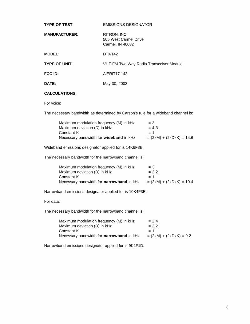
TYPE OF TEST: EMISSIONS DESIGNATOR MANUFACTURER: RITRON, INC. 505 West Carmel Drive Carmel, IN 46032 MODEL: DTX-142 TYPE OF UNIT: VHF-FM Two Way Radio Transceiver Module FCC ID: AIERIT17-142 DATE: May 30, 2003 CALCULATIONS: For voice: The necessary bandwidth as determined by Carson’s rule for a wideband channel is: Maximum modulation frequency (M) in kHz = 3 Maximum deviation (D) in kHz = 4.3 Constant K = 1 Necessary bandwidth for wideband in kHz = (2xM) + (2xDxK) = 14.6 Wideband emissions designator applied for is 14K6F3E. The necessary bandwidth for the narrowband channel is: Maximum modulation frequency (M) in kHz = 3 Maximum deviation (D) in kHz = 2.2 Constant K = 1 Necessary bandwidth for narrowband in kHz = (2xM) + (2xDxK) = 10.4 Narrowband emissions designator applied for is 10K4F3E. For data: The necessary bandwidth for the narrowband channel is: Maximum modulation frequency (M) in kHz = 2.4 Maximum deviation (D) in kHz = 2.2 Constant K = 1 Necessary bandwidth for narrowband in kHz = (2xM) + (2xDxK) = 9.2 Narrowband emissions designator applied for is 9K2F1D.

9
TYPE OF TEST: OCCUPIED BANDWIDTH FCC PART: 2.1049 (c)(1) per 90.210 (b)(d) MANUFACTURER: RITRON, INC. 505 West Carmel Drive Carmel, IN 46032 MODEL: DTX-142 TYPE OF UNIT: VHF-FM Two Way Radio Transceiver Module FCC ID: AIERIT17-142 DATE: May 30, 2003 PROCEDURE: 1. The DTX-142 was programmed for transmitter operation on 159.100 MHz, was set for 12.5 kHz
bandwidth operation, and the deviation was adjusted for +/- 2.2 kHz at 1000 Hz on channel (1). Channel (2) is programmed for 25 kHz wide band operation and yields +/- 4.3 kHz deviation at 1000 Hz.
2. The RF output of the DTX-142 was measured with a HP8920A communications test set wattmeter
at 5.0 watts. Power was supplied to the DTX-142 via a BK1730 power supply set at +13.8 VDC. 3. The antenna was connected to the HP8560E spectrum analyzer via a 20 dB power attenuator. 4. The output of the HP8920A audio function generator was applied to the microphone input of the
DTX-142. The frequency of the audio signal generator was set to 2500 Hz and the output adjusted to a level 16 dB greater than that necessary to produce 50% of the rated system deviation at the frequency of maximum response.
5. The spectrum analyzer was centered on 159.100 and the sidebands were read. The appropriate
narrow or wide band emission mask was also superimposed.

10
TYPE OF TEST: 12.5 kHz VOICE OCCUPIED BANDWIDTH FCC PART: 2.1049 (c)(1) per 90.210 (b)(d) MANUFACTURER: RITRON, INC. 505 West Carmel Drive Carmel, IN 46032 MODEL: DTX-142 TYPE OF UNIT: VHF-FM Two Way Radio Transceiver Module FCC ID: AIERIT17-142 DATE: May 30, 2003 RESULTS: Narrowband voice channel with 2500 Hz tone.

11
TYPE OF TEST: 25 kHz VOICE OCCUPIED BANDWIDTH FCC PART: 2.1049 (c)(1) per 90.210 (b)(d) MANUFACTURER: RITRON, INC. 505 West Carmel Drive Carmel, IN 46032 MODEL: DTX-142 TYPE OF UNIT: VHF-FM Two Way Radio Transceiver Module FCC ID: AIERIT17-142 DATE: May 30, 2003 RESULTS: Wideband voice with 2500 Hz tone.

12
TYPE OF TEST: 12.5 kHz RANDOM DATA OCCUPIED BANDWIDTH FCC PART: 2.1049 (c)(1) per 90.210 (b)(d) MANUFACTURER: RITRON, INC. 505 West Carmel Drive Carmel, IN 46032 MODEL: DTX-142 TYPE OF UNIT: VHF-FM Two Way Radio Transceiver Module FCC ID: AIERIT17-142 DATE: May 30, 2003 PROCEDURE: An 11 bit pseudo-random (PN) code generator producing 4-level data stream at 9600bps was connected to the AUX_IN port of the DTX-142. The auxiliary input gain adjust pot (R375) was adjusted to yield a peak deviation of 2.2 kHz. The following plot shows the occupied bandwidth well within the narrowband FCC limits. RESULTS:

13
TYPE OF TEST: 12.5 kHz UNIFORM DATA OCCUPIED BANDWIDTH FCC PART: 2.1049 (c)(1) per 90.210 (b)(d) MANUFACTURER: RITRON, INC. 505 West Carmel Drive Carmel, IN 46032 MODEL: DTX-142 TYPE OF UNIT: VHF-FM Two Way Radio Transceiver Module FCC ID: AIERIT17-142 DATE: May 30, 2003 PROCEDURE: A 2400 Hz square wave generator was connected to the AUX_IN port of the DTX-142. This represents an alternating 1,0,1,0 data pattern. The auxiliary input gain adjust pot (R375) was adjusted to yield a peak deviation of 2.2 kHz. The following plot shows the occupied bandwidth within the narrowband FCC limits. RESULTS:

14
TYPE OF TEST: SPURIOUS EMISSIONS AT ANTENNA TERMINALS FCC PART: 2.1051 MANUFACTURER: RITRON, INC. 505 West Carmel Drive Carmel, IN 46032 MODEL: DTX-142 TYPE OF UNIT: VHF-FM Two Way Radio Transceiver Module FCC ID: AIERIT17-142 DATE: May 30, 2003 PROCEDURE: The DTX-142 was programmed for transmitter operation 159.100 MHz. Power was supplied to the DTX-142 by a BK Precision Model 1730 Power Supply. The supply voltage was set to 13.8 VDC. The transmitter was modulated by a 2500 Hz tone at an input level 16 dB greater than that necessary to produce 50 percent modulation as specified in FCC Part 2.1049 (c)(1). The DTX-142 antenna terminal was connected to the input of a 20 dB power attenuator. After the attenuator and before a Hewlett-Packard Model 8559A Spectrum Analyzer a 272 MHz high pass filter was inserted. The measured insertion loss of the external attenuator and high pass filter are listed below. The spectrum was searched from 8 MHz to the 10th harmonic of the operating frequency. All unreported emissions are more than 20 dB below the FCC limit. RESULTS: Carrier Frequency: 159.100 MHz Power Output: 5.0 Watts Multiple Emission Analyzer Attenuator Spurious FCC dB below of Frequency Reading & filter Level Limit FCC Carrier (MHz) (dBm) Loss(dB) (dBm) (dBm) Limit 2 318.2000 -55.0 20.6 -35.4 -20 15.40 3 477.3000 -58.0 20.5 -37.5 -20 17.50

15
TYPE OF TEST: FIELD STRENGTH OF SPURIOUS RADIATION FCC PART: 2.1053 MANUFACTURER: RITRON, INC. 505 West Carmel Drive Carmel, IN 46032 MODEL: DTX-142 TYPE OF UNIT: VHF-FM Two Way Radio Transceiver Module FCC ID: AIERIT17-142 DATE: May 30, 2003 PROCEDURE: Field strength of spurious radiation of the DTX-142 was taken on the RITRON three-meter test range using the substitution method. The following procedure was used. 1. The DTX-142 was programmed to transmit at 5.0 watts on 159.100 MHz powered by a Ritron RPS-
1A power supply. 2. The DTX-142 was then terminated at the antenna port with 50 ohm power load. 3. All field strength measurements were made with the Hewlett-Packard Model 8560E Spectrum
Analyzer connected to the Electro-Metrics LPA-25 log periodic receive antenna. 4. A tuned Electro-Metrics dipole was substituted at the radio side of the range driven by a known
power level from the HP8657B to produce a known ERP at each harmonic. The receiving antenna was oriented both vertically and horizontally and reference measurements were taken at each harmonic. Cable loss from generator to the dipole was taken into account.
5. For each emission, the height and polarization of the field strength measuring antenna and
orientation of the DTX-142 were varied to find maximum field strength. 6. The spectrum was searched up to the 10th harmonic of the transmit frequency. All non-harmonics
were less than 20 dB below the FCC limits specified in Part 90.210(d)(3). EQUATIONS: Emission ERP (dBm) = Pgen (dBm) – Cable Loss (dB) – Ps (dBm) + Pr (dBm) Where: Pgen is the reference generator level. Cable Loss is the loss of the cable from the signal generator to the reference antenna. Ps is the level at the receiving antenna when the reference level is being transmitted. Pr is the level at the receiving antenna when the radio is substituted for the reference antenna.

16
TYPE OF TEST: FIELD STRENGTH OF SPURIOUS RADIATION FCC PART: 2.1053 MANUFACTURER: RITRON, INC. 505 West Carmel Drive Carmel, IN 46032 MODEL: DTX-142 TYPE OF UNIT: VHF-FM Two Way Radio Transceiver Module FCC ID: AIERIT17-142 DATE: May 30, 2003 RESULTS: Test Frequency: 159.1 MHz Test Power: 5.0 watts
DTX-142 – horizontal cable loss Emission FCC
freq(GHz) Pgen (dBm) (dB) Ps (dBm) Pr (dBm) ERP (dBm) Limit (dBm) margin(dB)
2 0.3182 0 0.1 -27.0 -72.3 -45.4 -20 25.4 3 0.4773 0 0.2 -28.8 -67.7 -39.1 -20 19.1 4 0.6364 0 0.3 -33.2 -70.3 -37.4 -20 17.4 5 0.7955 0 0.9 -37.3 -71.0 -34.6 -20 14.6 6 0.9546 0 1.0 -39.8 -65.5 -26.7 -20 6.7 7 1.1137 0 1.0 -46.2 -76.0 -30.8 -20 10.8 8 1.2728 0 1.2 -50.0 -78.7 -29.9 -20 9.9 9 1.4319 0 1.3 -52.2 -87.3 -36.4 -20 16.4
10 1.591 0 1.5 -51.8 -77.7 -27.4 -20 7.4 DTX-142 - vertical
cable loss Emission FCC
freq(GHz) Pgen (dBm) (dB) Ps (dBm) Pr (dBm) ERP(dBm) limit(dBm) margin(dB)
2 0.3182 0 0.1 -29.2 -74.2 -45.1 -20 25.1 3 0.4773 0 0.2 -30.7 -61.5 -31.0 -20 11.0 4 0.6364 0 0.3 -35.3 -63.5 -28.5 -20 8.5 5 0.7955 0 0.9 -38.3 -71.0 -33.6 -20 13.6 6 0.9546 0 1.0 -39.8 -65.2 -26.4 -20 6.4 7 1.1137 0 1.0 -47.8 -80.0 -33.2 -20 13.2 8 1.2728 0 1.2 -50.8 -85.7 -36.1 -20 16.1 9 1.4319 0 1.3 -49.5 -90.2 -42.0 -20 22.0
10 1.591 0 1.5 -51.5 -75.8 -25.8 -20 5.8
17
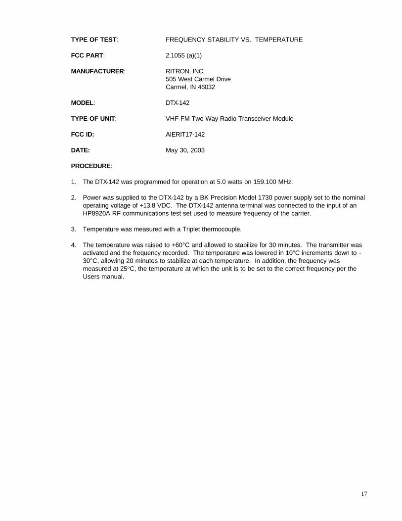
TYPE OF TEST: FREQUENCY STABILITY VS. TEMPERATURE FCC PART: 2.1055 (a)(1) MANUFACTURER: RITRON, INC. 505 West Carmel Drive Carmel, IN 46032 MODEL: DTX-142 TYPE OF UNIT: VHF-FM Two Way Radio Transceiver Module FCC ID: AIERIT17-142 DATE: May 30, 2003 PROCEDURE: 1. The DTX-142 was programmed for operation at 5.0 watts on 159.100 MHz. 2. Power was supplied to the DTX-142 by a BK Precision Model 1730 power supply set to the nominal
operating voltage of +13.8 VDC. The DTX-142 antenna terminal was connected to the input of an HP8920A RF communications test set used to measure frequency of the carrier.
3. Temperature was measured with a Triplet thermocouple. 4. The temperature was raised to +60°C and allowed to stabilize for 30 minutes. The transmitter was
activated and the frequency recorded. The temperature was lowered in 10°C increments down to -30°C, allowing 20 minutes to stabilize at each temperature. In addition, the frequency was measured at 25°C, the temperature at which the unit is to be set to the correct frequency per the Users manual.

18
TYPE OF TEST: FREQUENCY STABILITY VS. TEMPERATURE FCC PART: 2.1055 (a)(1) MANUFACTURER: RITRON, INC. 505 West Carmel Drive Carmel, IN 46032 MODEL: DTX-142 TYPE OF UNIT: VHF-FM Two Way Radio Transceiver Module FCC ID: AIERIT17-142 DATE: May 30, 2003 RESULTS:
Frequency Error vs Temperature
-3
-2
-1
0
1
2
3
-30 -20 -10 0 10 20 30 40 50
Temperature (C)
Err
or
(PP
M)
Frequency Error
Upper Limit
Lower Limit
19
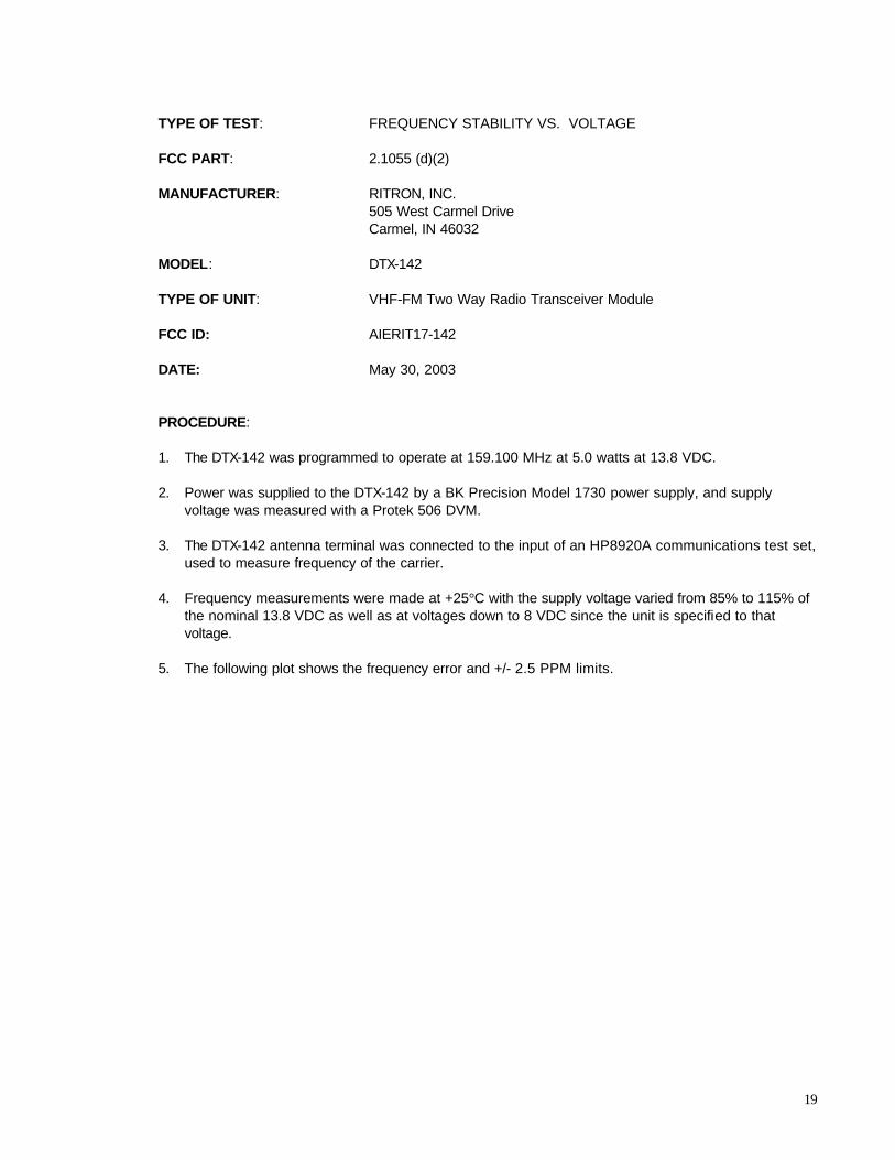
TYPE OF TEST: FREQUENCY STABILITY VS. VOLTAGE FCC PART: 2.1055 (d)(2) MANUFACTURER: RITRON, INC. 505 West Carmel Drive Carmel, IN 46032 MODEL: DTX-142 TYPE OF UNIT: VHF-FM Two Way Radio Transceiver Module FCC ID: AIERIT17-142 DATE: May 30, 2003 PROCEDURE: 1. The DTX-142 was programmed to operate at 159.100 MHz at 5.0 watts at 13.8 VDC. 2. Power was supplied to the DTX-142 by a BK Precision Model 1730 power supply, and supply
voltage was measured with a Protek 506 DVM. 3. The DTX-142 antenna terminal was connected to the input of an HP8920A communications test set,
used to measure frequency of the carrier. 4. Frequency measurements were made at +25°C with the supply voltage varied from 85% to 115% of
the nominal 13.8 VDC as well as at voltages down to 8 VDC since the unit is specified to that voltage.
5. The following plot shows the frequency error and +/- 2.5 PPM limits.

20
TYPE OF TEST: FREQUENCY STABILITY VS. VOLTAGE FCC PART: 2.1055 (d)(2) MANUFACTURER: RITRON, INC. 505 West Carmel Drive Carmel, IN 46032 MODEL: DTX-142 TYPE OF UNIT: VHF-FM Two Way Radio Transceiver Module FCC ID: AIERIT17-142 DATE: May 30, 2003 RESULTS:
Frequency Error VS Supply Voltage
-3
-2
-1
0
1
2
3
8 9 10 11 12 13 14 15 16
Supply Voltage (VDC)
Err
or
(PP
M)
Frequency Error
Lower LimitUpper Limit

21
TYPE OF TEST: TRANSIENT FREQUENCY BEHAVIOR FCC PART: 90.214 MANUFACTURER: RITRON, INC. 505 West Carmel Drive Carmel, IN 46032 MODEL: DTX-142 TYPE OF UNIT: VHF-FM Two Way Radio Transceiver Module FCC ID: AIERIT17-142 DATE: May 30, 2003 PROCEDURE: The DTX-142 was aligned for transmitter operation on 159.100 MHz at 5.0 watts. 1. The test equipment was connected per the following diagram:
2. The HP8920A receiver was set to measure FM deviation with the audio bandwidth set at ≤ 20 Hz to
≥15 kHz and the RF frequency set to 159.100 MHz.
3. The HP8920A RF signal generator was set to 159.100 MHz with a 1 kHz tone at ±12.5 kHz deviation. The output level of the signal generator was set such that its level at the Antenna Input of the HP8920A Test Set was 30 dB below that of the level of the DTX-142 when it was keyed.
4. The Trigger Level of the Philips PM-3335 was set such that it triggered on when RF power from the
DTX-142 was either detected or lost. For the transmitter turn-on waveforms, the delay was set such that the trigger point was 1 division from the left of the screen. Conversely, for turn-off waveforms, the delay was set for 1 division from the right side of the screen.
DTX-142 Under test
Bird 8306-300-N 50Ω/30dB attenuators
Power splitter
RF detector
3-way combining network
HP8920A Communications
Test Set
RF Signal Generator Output
Antenna Input
Demodulated Audio Output
Philips PM-3335 Digital Storage Oscilloscope
Vertical Input
Trigger Input

22
5. The trigger was set for positive, the unit keyed and the resulting waveform stored. The trigger was
then set for negative, the unit keyed and the resulting waveform stored. 6. The FCC limits per Part 90.214 were added to the plot in the same manner illustrated in EIA-603-B
Part 3.2.19.2

23
TYPE OF TEST: TRANSIENT FREQUENCY BEHAVIOR FCC PART: 90.214 MANUFACTURER: RITRON, INC. 505 West Carmel Drive Carmel, IN 46032 MODEL: DTX-142 TYPE OF UNIT: VHF-FM Two Way Radio Transceiver Module FCC ID: AIERIT17-142 DATE: May 30, 2003 SWITCH ON CONDITION ton, t1, and t2
B
Vertical = 3.125/div Horizontal = 10 ms/div
SWITCH ON
12.5 kHz
6.25 kHz
-6.25 kHz
-12.5 kHz
t1 t2

24
TYPE OF TEST: TRANSIENT FREQUENCY BEHAVIOR FCC PART: 90.214 MANUFACTURER: RITRON, INC. 505 West Carmel Drive Carmel, IN 46032 MODEL: DTX-142 TYPE OF UNIT: VHF-FM Two Way Radio Transceiver Module FCC ID: AIERIT17-142 DATE: May 30, 2003
B
SWITCH OFF
Vertical = 3.125 kHz/div Horizontal = 10 msec/div
12.5 kHz
6.25 kHz
-6.25 kHz
-12.5 kHz
t3