type test report for uninterruptible power systems model: ea200n … 1000-1500va ce-lvd...
TRANSCRIPT

TYPE TEST REPORT FOR
Uninterruptible Power Systems
Model: EA200N series (1000VA, 1200VA, 1500VA, 1570VA, 1600VA)
Prepared for : GUANGDONG EAST POWER CO., LTD. NO.6 NORTHERN INDUSTRY ROAD, SONGSHAN LAKE SCI&TECH INDUSTRY PARK, DONGGUAN, P.R.CHINA
Tel: +86-769-22897777 Fax: +86-769-22898866
Prepared By : WALTEK SERVICES (SHENZHEN) CO ., LTD. 12B, West Tower, Aidi Building, No.5003 Binhe Rd, Futian District, Shenzhen 518045, China Tel: +86-755-83551033 Fax: +86-755-83552400
Date of Test: November 11, 2010 to December 6, 2010 Date of Report: December 18, 2010 Report Number: WT10114467-S-S-L

page 1 of 27
WALTEK SERVICES Project Engineer: Wing Ye Reference No.: WT10114467-S-S-L TRF No.: EN62040_1_1A
TEST REPORT
EN 62040-1:2008 Uninterruptible power systems (UPS) –
Part 1: General and safety requirements for UPS Report reference No. . ......................: WT10114467-S-S-L Compiled by (+ signature) ..............: Wing Ye
........................................................
Approved by (+ signature) ................: Oren Yang
........................................................
Date of issue ....................................: December 18, 2010
Contents ...........................................: 27 pages and 5 pages photo documents
Testing Laboratory Name ................: Waltek Services
Address ............................................: 12B, West Tower, Aidi Building, No. 5003 Binhe Rd, Futian District, Shenzhen, China
Testing location ...............................: 1/F, Fukangtai Building, Baima Rd., Songgang Street, Baoan District, Shenzhen 518105, China.
Applicant's Name .............................: GUANGDONG EAST POWER CO., LTD.
Address ............................................: NO.6 NORTHERN INDUSTRY ROAD, SONGSHAN LAKE SCI&TECH INDUSTRY PARK, DONGGUAN, P.R.CHINA
Standard ...........................................: EN 62040-1:2008
Test Report Form No........................: EN62040_1_1A
TRF originator ..................................: SGS Fimko Ltd
Master TRF ......................................: dated 2003-03
Copyright blank test report ...............: The bodies participating in the Committee of Certification Bodies (CCB) and/or the bodies participating in the CENELEC Certification Agreement (CCA).
Test procedure .................................. : CCA-scheme Procedure deviation........................... : N.A Non-standard test method ................. : N.A
Type of test object ............................: Uninterruptible Power Systems
Trademark .......................................: N.A
Manufacturer ...................................: GUANGDONG EAST POWER CO., LTD
Model and/or type reference ...........: EA200N series (1000VA, 1200VA, 1500VA, 1570VA, 1600VA)
Serial number ..................................: Engineer sample, no serial number Rating(s) ...........................................: See model list

page 2 of 27
WALTEK SERVICES Project Engineer: Wing Ye Reference No.: WT10114467-S-S-L TRF No.: EN62040_1_1A
General descriptions: The subject models are the Uninterruptible Power Systems. All tests were performed on provided test samples and found that they complied with the requirements of the standards. Tests are performed on models 1200VA and 1600VA to indicate the other models. Model difference:
Model
Place
1000VA 1200VA
1500VA 1570VA 1600VA
Battery 2-12V7AH 2-12V8AH
Transformer EI 114*60
EI 133*50
Dimension W*H* D 355 * 145 * 215
PCB layout All models using the same PCB
layout
Copy of marking plate
GUANGDONG EAST POWER CO., LTD Uninterruptible Power Systems Model No: 1200VA Input: 220-240V~, 50/60Hz, 5A Output: 200-240V~, 50/60Hz, 3.2A, 1φ with neutral
Made in China
GUANGDONG EAST POWER CO., LTD Uninterruptible Power Systems Model No: 1600VA Input: 220-240V~, 50/60Hz, 6A Output: 200-240V~, 50/60Hz, 4.3A, 1φ with neutral
Made in China

page 3 of 27
WALTEK SERVICES Project Engineer: Wing Ye Reference No.: WT10114467-S-S-L TRF No.: EN62040_1_1A
Particulars: test item vs. test requirements Equipment mobility ..................................... : Movable Operating condition ..................................... : Continuous Tested for IT power systems ...................... : No IT testing, phase-phase voltage (V) ........... : N/A
Class of equipment ..................................... : Class I Mass of equipment (kg) ............................... : 11.9 kg for model 1200VA
13.5 kg for model 1600VA Protection against ingress of water ............ : IPX0 Test case verdicts
Test case does not apply to the test object : N(.A)
Test item does meet the requirement ......... : P(ass)
Test item does not meet the requirement ... : F(ail)
Testing
Date of receipt of test item .......................... : November 10, 2010
Date(s) of performance of test .................... : November 11, 2010 to December 6, 2010
General remarks
The test result presented in this report relate only to the object(s) tested. This report shall not be reproduced, except in full, without the written approval of the Issuing testing laboratory.
”(see Enclosure #)" refers to additional information appended to the report. "(see appended table)" refers to a table appended to the report.
Standard EN 62040-1:2008 is to be used in conjunction with EN 60950-1:2006+A11:2009, which is referred to in this TRF by "RD".
Model list
Model Rated Input voltage(V)
Rated Input frequency (Hz)
Rated Input apparent power(VA)
Rated Input current(A)
Rated output voltage(V)
Rated output frequency (Hz)
Rated output current (A)
1000VA 220-240 50/60 1000 5 200-240 50/60 2.7
1200VA 220-240 50/60 1200 5 200-240 50/60 3.2
1500VA 220-240 50/60 1500 6 200-240 50/60 4.0
1570VA 220-240 50/60 1570 6 200-240 50/60 4.0
1600VA 220-240 50/60 1600 6 200-240 50/60 4.3

page 4 of 27
WALTEK SERVICES Project Engineer: Wing Ye Reference No.: WT10114467-S-S-L TRF No.: EN62040_1_1A
EN 62040-1:2008
Clause Requirement – Test Result – Remark Verdict
4 GENERAL CONDITIONS FOR TESTS P
4.5 Components P
1.5.1/RD General P
Comply with IEC 60950-1 or relevant component standard
All safety critical components are certified, all components are used within their rating, plastic materials, PCBs and wiring material are UL listed, non-certified components were tested according to this standard. (See appended table 4.3)
P
1.5.2/RD Evaluation and testing of components P
1.5.4/RD Transformers Transformer complies with the relevant requirements of the standard and particularly with Annex C/RD.
P
1.5.5/RD Interconnecting cables P
1.5.6/RD Capacitors in primary circuits ..................... N
1.5.7/RD Double insulation or reinforced insulation bridged by components
No such components N
1.5.7.1/RD General N
1.5.7.2/RD Bridging capacitors No such capacitors N
1.5.7.3/RD Bridging resistors No such resistors N
1.5.8/RD Components in equipment for IT power systems
Not for IT power systems N
4.6 Power interface P
1.6.1/RD AC power distribution systems TN power system P
1.6.2/RD Input current (see appended table 4.4) P
1.6.4/RD Neutral conductor Neutral is identified in the equipment. Basic insulation for rated voltage between earthed parts and primary phases.
P
4.7 Marking and instructions P
4.7.1 General P
4.7.2 Power rating P
Input rated voltage/range (V) ...................... 220-240 P
Input rated current/range (A)....................... See model list P
Input symbol for nature of supply (d.c.) ...... AC supply N
Input rated frequency/range (Hz) ................ 50/60 P
Output rated voltage/range (V) ................... 200-240 P
Output rated current/range (A) ................... See model list N

page 5 of 27
WALTEK SERVICES Project Engineer: Wing Ye Reference No.: WT10114467-S-S-L TRF No.: EN62040_1_1A
EN 62040-1:2008
Clause Requirement – Test Result – Remark Verdict
Number of output phases (1φ - 3φ) with/without neutral......................................
1φ with neutral P
Output rated active power (W) ................... N
Output rated apparent power (VA) ............. N
Output symbol for nature of supply (d.c.) ... AC supply N
Rated frequency or rated frequency range (Hz):
50/60 P
Max. ambient operating temperature range (°C)...................................................
25 P
Manufacturer’s name or trademark or identification mark ......................................
GUANGDONG EAST POWER CO., LTD P
Type/model or type reference ..................... EA200N series (1000VA, 1200VA, 1500VA, 1570VA, 1600VA)
P
Symbol for Class II equipment only ............ Class I N
Other symbols ............................................ P
Certification marks ...................................... P
Instructions for units with automatic bypass/maintenance bypass, additional input a.c. supply, or external batteries, having text "See installation instructions before connecting to the supply" ................
No separated bypass. N
4.7.3 Safety instructions P
Guidance for installation for operator and service person ............................................
User manual P
Warning label with text "Isolate uninterruptible power supply (UPS) before working on this circuit"
Pluggable type A, not permanently connected UPS without internal automatic backfeed isolation
N
4.7.4 Main voltage adjustment ............................ No such device N
1.7.4/RD Supply voltage adjustment ......................... N
Methods and means of adjustment; reference to installation instructions ...........
N
4.5.5 1.7.5/RD
Power outlets............................................... The maximum apparent and active power of the standard appliance outlets is indicated on the rear of the enclosure adjacent to the appliance outlets. Conforming to IEC 60083.
P
4.5.6 1.7.6/RD
Fuse identification (marking, special fusing characteristics, cross-reference) ................
Part of appliance inlet, or fuse holder, VDE approved
P
4.5.7 1.7.7/RD
Wiring terminals P
1.7.7.1/RD Protective earthing and bonding terminals .
P
1.7.7.2/RD Terminal for a.c. mains supply conductors N

page 6 of 27
WALTEK SERVICES Project Engineer: Wing Ye Reference No.: WT10114467-S-S-L TRF No.: EN62040_1_1A
EN 62040-1:2008
Clause Requirement – Test Result – Remark Verdict
1.7.7.3/RD Terminals for d.c. mains supply conductors ..................................................
N
4.7.8 Battery terminals ........................................ Polarity is indicated (+ and -) on the batteries.
P
4.7.9 1.7.8/RD
Controls and indicators P
1.7.8.1/RD Identification, location and marking ............ Front panel P
1.7.8.2/RD Colours ...................................................... Green, yellow and red of indicator are just for function purpose.
P
1.7.8.3/RD Symbols according to IEC 60417................ N
1.7.8.4/RD Markings using figures .............................. N
4.7.10 1.7.9/RD
Isolation of multiple power sources ............ Only one supply from the mains. N
4.7.11 IT power systems N
1.7.2.4/RD IT power distribution systems N
4.7.12 Protection in building installations Pluggable equipment type A. N
4.7.13 5.1/RD
High leakage current (mA) ......................... RS232 connector: max. 0.022 Enclosure: max. 1.624 Front enclosure with foil: max. 0.021
P
4.7.14 1.7.10/RD
Thermostats and other regulating devices No thermostats or regulating devices used.
N
4.7.15 1.7.2.1/RD
Language(s) ............................................... English P
4.7.16 1.7.11/RD
Durability of markings After rubbing test by water and petroleum spirit, the label still easily discernible, indelible and legible.
P
4.7.17 1.7.12/RD
Removable parts No removable parts. N
4.7.18 1.7.13/RD
Replaceable batteries Irreplaceable N
4.7.19 1.7.2.5/RD
Operator access with a tool......................... N
4.7.20 Battery Pluggable type A, UPS battery is located in battery compartment. See page 2 Model difference
P
Clearly legible information .......................... On battery cell P
Battery type ................................................ Lead-acid P
Nominal voltage of total battery (V) ............ See page 2 Model difference P
Nominal capacity of total battery (optional) ....................................................
See page 2 Model difference P
Warning label ............................................. On battery compartment P
Instructions ................................................. User manual P
page 7 of 27
WALTEK SERVICES Project Engineer: Wing Ye Reference No.: WT10114467-S-S-L TRF No.: EN62040_1_1A
EN 62040-1:2008
Clause Requirement – Test Result – Remark Verdict
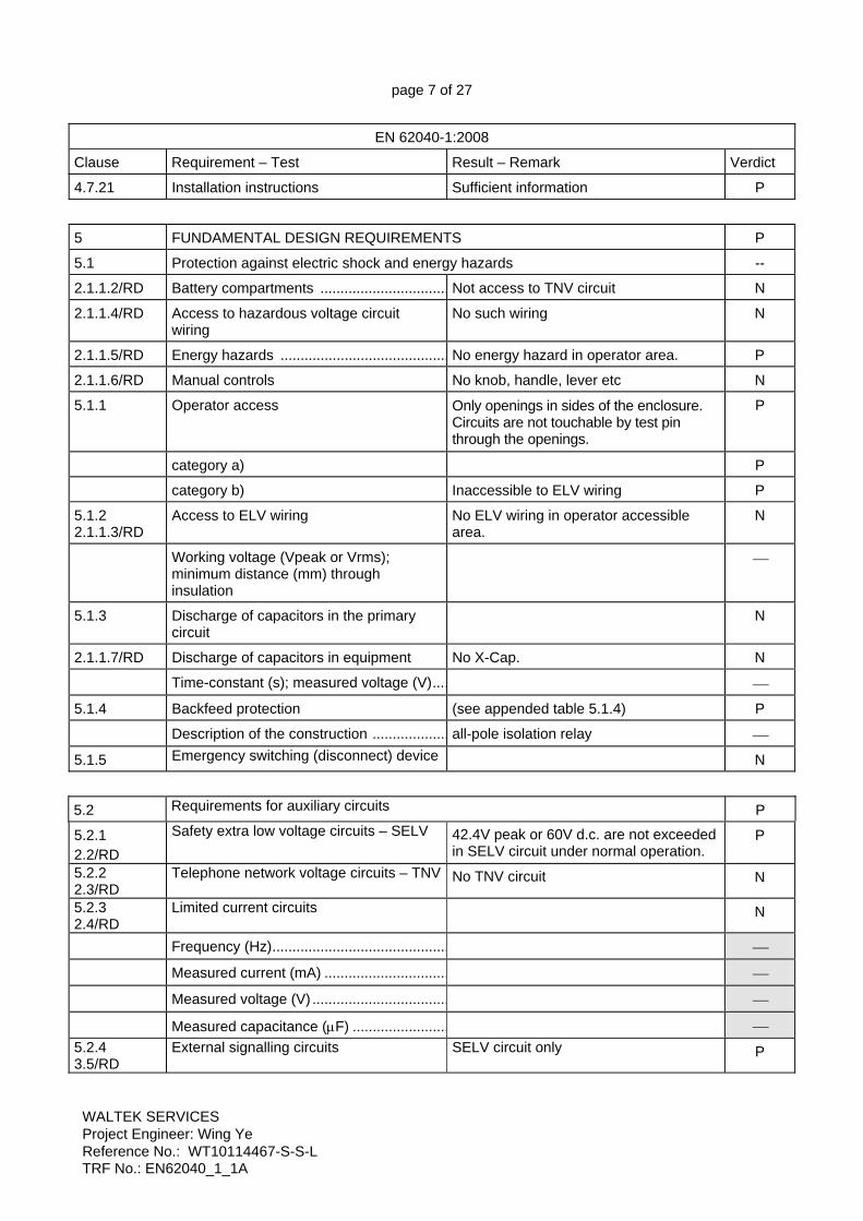
4.7.21 Installation instructions Sufficient information P
5 FUNDAMENTAL DESIGN REQUIREMENTS P
5.1 Protection against electric shock and energy hazards --
2.1.1.2/RD Battery compartments ................................ Not access to TNV circuit N
2.1.1.4/RD Access to hazardous voltage circuit wiring
No such wiring N
2.1.1.5/RD Energy hazards .......................................... No energy hazard in operator area. P
2.1.1.6/RD Manual controls No knob, handle, lever etc N
5.1.1 Operator access Only openings in sides of the enclosure. Circuits are not touchable by test pin through the openings.
P
category a) P
category b) Inaccessible to ELV wiring P
5.1.2 2.1.1.3/RD
Access to ELV wiring No ELV wiring in operator accessible area.
N
Working voltage (Vpeak or Vrms); minimum distance (mm) through insulation
⎯
5.1.3 Discharge of capacitors in the primary circuit
N
2.1.1.7/RD Discharge of capacitors in equipment No X-Cap. N
Time-constant (s); measured voltage (V).... ⎯
5.1.4 Backfeed protection (see appended table 5.1.4) P
Description of the construction ................... all-pole isolation relay ⎯
5.1.5 Emergency switching (disconnect) device N
5.2 Requirements for auxiliary circuits P
5.2.1 2.2/RD
Safety extra low voltage circuits – SELV 42.4V peak or 60V d.c. are not exceeded in SELV circuit under normal operation.
P
5.2.2 2.3/RD
Telephone network voltage circuits – TNV
No TNV circuit N
5.2.3 2.4/RD
Limited current circuits
N
Frequency (Hz)............................................ ⎯ Measured current (mA) ............................... ⎯ Measured voltage (V) .................................. ⎯ Measured capacitance (μF) ........................ ⎯ 5.2.4 3.5/RD
External signalling circuits
SELV circuit only P

page 8 of 27
WALTEK SERVICES Project Engineer: Wing Ye Reference No.: WT10114467-S-S-L TRF No.: EN62040_1_1A
EN 62040-1:2008
Clause Requirement – Test Result – Remark Verdict 5.2.5 2.5/RD
Limited power source
N
5.3 Protective earthing and bonding P
5.3.1 2.6/RD
General
P
5.3.2
Protective earthing P
5.3.3 Protective bonding P
5.4 AC and d.c. power isolation N
5.4.1 3.4/RD
General N
5.4.2 Disconnect devices N
5.5 Overcurrent and earth fault protection P
5.5.1 General P 2.7.3/RD
Short-circuit backup protection Pluggable equipment type A. The building installation is considered as providing short-circuit backup protection.
P
2.7.4/RD
Number and location of protective devices....:
One protective device current fuse is located in Line.
P
2.7.5/RD
Protection by several devices Only one used P
2.7.6/RD
Warning to service personnel………………..:
No service work necessary. N
5.5.2 Basic requirements P
5.5.3 Battery circuit protection.............................. P
5.5.3.1 Overcurrent and earth fault protection Installed inside with a protective device – DC Fuse
P
5.5.3.2 Location of protective devices Fixing in PCB P
5.5.3.3 Rating of protective devices Comply 8.3 P
5.6 Protection of personnel – Safety interlocks
No such device N
5.6.1 2.8/RD
Operator protection ..................................... N
5.6.2 Service person protection N
5.6.2.1 Introduction N
5.6.2.2 Covers N

page 9 of 27
WALTEK SERVICES Project Engineer: Wing Ye Reference No.: WT10114467-S-S-L TRF No.: EN62040_1_1A
EN 62040-1:2008
Clause Requirement – Test Result – Remark Verdict
5.6.2.3 Location and guarding of parts N
5.6.2.4 Parts on doors N
5.6.2.5 Component access N
5.6.2.6 Moving parts N
5.6.2.7 Capacitor banks N
5.6.2.8 Internal batteries N
5.7 2.10/RD
Clearances, creepage distances and distances through insulation P
2.10.1/RD General P
2.10.1.1/RD Frequency……..………………………………:
P
2.10.1.2/RD Pollution degrees……….……..………………:
Pollution Degree 2 P
2.10.1.3/RD Reduced values for functional insulation N
2.10.1.4/RD Intervening unconnected conductive parts N
2.10.1.5/RD Insulation with varying dimensions N
2.10.1.6/RD Special separation requirements N
2.10.1.7/RD Insulation in circuits generating starting pulses
N
2.10.2/RD Determination of working voltage P
2.10.2.1/RD General (See appended table 5.7) P
2.10.2.2/RD RMS working voltage P
2.10.2.3/RD Peak working voltage P
2.10.3/RD Clearances (See appended table 5.7) P
2.10.3.1/RD General P
2.10.3.2/RD Mains transient voltages P
a) AC mains supply …………………………..:
2500Vp P
b) Earthed d.c. mains supplies ………….….:
N
c) Unearthed d.c. mains supplies ……….….:
N
d) Battery operation ………………..…………:
N
2.10.3.3/RD Clearances in primary circuits (See appended table 5.7) P
2.10.3.4/RD Clearances in secondary circuits N
2.10.3.5/RD Clearances in circuits having starting pulses
N

page 10 of 27
WALTEK SERVICES Project Engineer: Wing Ye Reference No.: WT10114467-S-S-L TRF No.: EN62040_1_1A
EN 62040-1:2008
Clause Requirement – Test Result – Remark Verdict
2.10.3.6/RD Transients from a.c. mains supply ……..…...:
P
2.10.3.7/RD Transients from d.c. mains supply ……….…:
N
2.10.3.8/RD Transients from telecommunication networks and cable distribution systems ……………..:
N
2.10.3.9/RD Measurement of transient voltage levels N
a) Transients from a mains supply N
For an a.c. mains supply ……………………:
N
For a d.c. mains supply ……………………..:
N
b) Transients from a telecommunication network
N
2.10.4/RD Creepage distances (See appended table 5.7) P
2.10.4.1/RD General P
2.10.4.2/RD Material group and comparative tracking index
P
CTI tests …………………………..…………..:
Material group IIIb are assumed to be used
⎯
2.10.4.3/RD Minimum creepage distances (See appended table 5.7) P
2.10.5/RD Solid insulation P
2.10.5.1/RD General P
2.10.5.2/RD Distances through insulation P
2.10.5.3/RD Insulating compound as solid insulation N
2.10.5.4/RD Semiconductor devices N
2.10.5.5/RD Cemented joints N
2.10.5.6/RD Thin sheet material - General P
2.10.5.7/RD Separable thin sheet material P
Number of layers (pcs)……………………….:
2 layers ⎯
2.10.5.8/RD Non-separable thin sheet material N
2.10.5.9/RD Thin sheet material – standard test procedure
N
Electric strength test ⎯
2.10.5.10/RD Thin sheet material – alternative test procedure
P
Electric strength test P
2.10.5.11/RD Insulation in wound components P
2.10.5.12/RD Wire in wound components P

page 11 of 27
WALTEK SERVICES Project Engineer: Wing Ye Reference No.: WT10114467-S-S-L TRF No.: EN62040_1_1A
EN 62040-1:2008
Clause Requirement – Test Result – Remark Verdict
Working voltage ………………………………:
P
a) Basic insulation not under stress ………..:
N
b) Basic, supplementary, reinforced insulation ………………………………………:
P
c) Compliance with Annex U ………………..:
P
Two wires in contact inside wound components; angle between 45o and 90o …:
N
2.10.5.13/RD Wire with solvent-based enamel in wound components
N
Electric strength test N
Routine test N
2.10.5.14/RD Additional insulation in wound components
N
Working voltage ………………………………:
N
- Basic insulation not under stress ………….:
N
- Supplementary, reinforced insulation …….:
N
2.10.6/RD Construction of printed boards P
2.10.6.1/RD Uncoated printed boards P
2.10.6.2/RD Coated printed boards N
2.10.6.3/RD Insulation between conductors on the same inner surface of a printed board
N
2.10.6.4/RD Insulation between conductors on different layers of a printed board
N
Distance through insulation N
Number of insulation layers (pcs) …………..:
N
2.10.7/RD Component external terminations N
2.10.8/RD Tests on coated printed boards and coated components
N
2.10.8.1/RD Sample preparation and preliminary inspection
N
2.10.8.2/RD Thermal conditioning N
2.10.8.3/RD Electric strength test N
2.10.8.4/RD Abrasion resistance test N

page 12 of 27
WALTEK SERVICES Project Engineer: Wing Ye Reference No.: WT10114467-S-S-L TRF No.: EN62040_1_1A
EN 62040-1:2008
Clause Requirement – Test Result – Remark Verdict
2.10.9/RD Thermal cycling N
2.10.10/RD Test for Pollution Degree 1 environment and insulating compound
N
2.10.11/RD Tests for semiconductor devices and cemented joints
N
2.10.12/RD Enclosed and sealed parts: No hermetically sealed components. N
6 Wiring, connections and supply P 6.1 Introduction P 6.1.2 Dimensions and ratings of busbars and
insulated conductors P
6.2 Connection to power P 6.2.1 General provisions for connection to
power A non-detachable power supply cord or a detachable power supply cord for an appliance inlet
P
3.2.2/RD Multiple supply connections Single supply connection. N 3.2.3/RD Permanently connected equipment Not permanently connected equipment. N Number of conductors, diameter of cable
and conduits (mm) …………………………...:
⎯
3.2.4/RD Appliance inlets P 3.2.5/RD Power supply cords P 3.2.5.1/RD AC power supply cords N Type ………………………………………...
….: N
Rated current (A), cross-sectional area (mm2), AWG ………………………………….:
⎯
3.2.5.2/RD DC power supply cords N 3.2.6/RD Cord anchorages and strain relief N Mass of equipment (kg), pull
(N) .……..……: ⎯
Longitudinal displacement (mm) ………..….:
⎯
3.2.7/RD Protection against mechanical damage P 3.2.8/RD Cord guards P Diameter or minor dimension D (mm); test
mass (g) ……………………………………....:
⎯
Radius of curvature of cord (mm) ……..……:
⎯

page 13 of 27
WALTEK SERVICES Project Engineer: Wing Ye Reference No.: WT10114467-S-S-L TRF No.: EN62040_1_1A
EN 62040-1:2008
Clause Requirement – Test Result – Remark Verdict 6.2.2 Means of connection Pluggable UPS type A
Detachable power supply cord P
6.3 Wiring terminals for external power conductors N 3.3/RD Wiring terminals for connection of
external conductors N
3.3.1 Wiring terminals N
3.3.2 Connection of non-detachable power supply cords
N
3.3.3 Screw terminals N
3.3.4 Conductor sizes to be connected N
Rated current (A), cord/cable type, cross-sectional area (mm2) …………………………:
⎯
3.3.5 Wiring terminal sizes N
Rated current (A), type, nominal thread diameter (mm) ………………………………...:
⎯
3.3.6 Wiring terminals design N
3.3.7 Grouping of wiring terminals N
3.3.8 Stranded wire N
7
Physical requirements
P
7.1 Enclosure No carry current P 7.2 4.1/RD
Stability 10°, no tip P
7.3 4.2/RD
Mechanical strength 250N, 5s P
4.2.1/RD General P
4.2.2/RD Steady force test, 10 N P
4.2.3/RD Steady force test, 30 N . P
4.2.4/RD Steady force test, 250 N Enclosure, 5s, no damage P
4.2.5/RD Impact test 1.3m P
Fall test For top enclosure ⎯
Swing test For right side, left side, front side and back side
⎯
4.2.6/RD Drop test; height (mm) ……………………….:
N
4.2.7/RD Stress relief test 70°C, 7 hours P
4.2.8/RD Cathode ray tubes No CRT. N

page 14 of 27
WALTEK SERVICES Project Engineer: Wing Ye Reference No.: WT10114467-S-S-L TRF No.: EN62040_1_1A
EN 62040-1:2008
Clause Requirement – Test Result – Remark Verdict
Picture tube separately certified …………….:
N
4.2.9/RD High pressure lamps No high pressure lamps. N
4.2.10/RD Wall or ceiling mounted equipment; force (N) ………………………………………………:
Not wall or ceiling mounted equipment. N
7.4
Construction details
P
7.4.1
Introduction
P
4.3.1/RD
Edges and corners Edges and corners of the enclosure are rounded.
P
4.3.2/RD
Handles and manual controls; force (N) ……:
No handles or manual controls. N
4.3.3/RD
Adjustable controls No adjustable controls. N
4.3.4/RD
Securing of parts P
4.3.5/RD
Connection by plugs and sockets N
4.3.7/RD
Heating elements in earthed equipment N
4.3.11/RD
Containers for liquids or gases N
4.4/RD
Protection against hazardous moving parts
No moving part N
4.4.1/RD
General N
4.4.2/RD Protection in operator access areas N 4.4.3/RD Protection in restricted access locations N 4.4.4/RD Protection in service access areas N
7.4.2 Openings For side opening, no hazardous and energy hazard parts are located in projection area, which vertically, or within a 5 degree angle from the edges of the openings.
P
7.4.3 Gas concentration See 7.6 P
7.4.4 Equipment movement N
7.5 4.7/RD
Resistance to fire Electrical parts not likely to ignite nearby materials and the fire enclosures used
P
4.7.2/RD Conditions for a fire enclosure All components located in a fire enclosure and metal enclosure.
P
7.6 Battery location P
7.6.1 Battery location and installation Installed inside P
7.6.2 Accessibility and maintainability P
7.6.3 Distance Ventilation P

page 15 of 27
WALTEK SERVICES Project Engineer: Wing Ye Reference No.: WT10114467-S-S-L TRF No.: EN62040_1_1A
EN 62040-1:2008
Clause Requirement – Test Result – Remark Verdict 7.6.4 Case insulation P 7.6.5 Wiring P 7.6.6 Electrolyte spillage VRLA battery N 7.6.7 Ventilation P 7.6.8 Charging voltages P
7.7 Temperature rise P
Maximum temperatures (see appended table 7.7) P
4.5.2/RD Resistance to abnormal heat Ball pressure test (see appended table 7.7)
P
8 ELECTRICAL REQUIREMENTS AND SIMULATED ABNORMAL CONDITIONS P 8.1 5.1.1/RD
General P
5.1.2/RD Equipment under test (EUT) N
5.1.7/RD Equipment with touch current exceeding 3.5 mA ........................................................
See 4.7.13 P
8.2 Electric strength P
5.2.1/RD General (see appended table 5.7) P
5.2.2/RD Test procedure (see appended table 5.7) P
8.3 Abnormal operating and fault conditions P
5.3.1/RD Protection against overload and abnormal operation
(see appended table 8.3) P
5.3.2/RD Motors No motor N
5.3.3/RD Transformers (see appended Annex C) P
5.3.4/RD Functional insulation.................................... P
5.3.5/RD Electromechanical components P
5.3.8/RD Compliance criteria for abnormal operating and fault conditions
(see appended table 8.3) P
8.3.1 Simulation of faults (see appended table 8.3) P
8.3.2 Conditions for tests P
9 CONNECTION TO TELECOMMUNICATION NETWORKS N
6.1/RD Protection of telecommunication network service persons, and users of other equipment connected to the network, from hazards in the equipment
--
6.1.1/RD Protection from hazardous voltages N
6.1.2/RD Separation of the telecommunication network from earth N
6.1.2.1/RD Requirements N

page 16 of 27
WALTEK SERVICES Project Engineer: Wing Ye Reference No.: WT10114467-S-S-L TRF No.: EN62040_1_1A
EN 62040-1:2008
Clause Requirement – Test Result – Remark Verdict
Test voltage (V) .......................................... ⎯
Current in the test circuit (mA) ................. ⎯
6.1.2.2/RD Exclusions ................................................... N
6.2/RD Protection of equipment users from overvoltages on telecommunication networks N
6.2.1/RD Separation requirements N
6.2.2/RD Electric strength test procedure N
6.2.2.1/RD Impulse test N
6.2.2.2/RD Steady-state test N
6.2.2.3/RD Compliance criteria N
6.3/RD Protection of the telecommunication wiring system from overheating N
Max. output current (A)................................ N.A ⎯
Current limiting method ............................... N.A ⎯
1.4.8/RD Normal operating voltages ......................... N
1.4.11/RD Power from a telecommunication network .....................................................................
N
2.1.1/RD Protection in operator access areas N
2.1.1.1/RD Access to energized parts N
Test by inspection ...................................... N
Test with test finger .................................... N
Test with test pin ........................................ N
Test with test probe .................................... N
2.1.1.2/RD Battery compartments ................................ N
2.1.3/RD Protection in restricted access locations N
2.3/RD TNV circuits N
2.3.1/RD Limits N
Type of TNV circuits .................................... N.A ⎯
2.3.2/RD Separation from other circuits and from accessible parts
N
Insulation employed .................................... N.A ⎯
2.3.3/RD Separation from hazardous voltages N
Insulation employed .................................... N.A ⎯
2.3.4/RD Connection of TNV circuits to other circuits
N
Insulation employed .................................... N.A ⎯
2.3.5/RD Test for operating voltages generated externally
N

page 17 of 27
WALTEK SERVICES Project Engineer: Wing Ye Reference No.: WT10114467-S-S-L TRF No.: EN62040_1_1A
EN 62040-1:2008
Clause Requirement – Test Result – Remark Verdict
2.6.1/RD Protective earthing N
2.6.5.8/RD Reliance on telecommunication network or cable distribution system
N
2.9.3/RD Grade of insulation N
2.10.3.3/RD Clearances in secondary circuits N
2.10.3.4/RD Measurement of transient voltage levels N
2.10.4/RD Creepage distances N
3.5/RD Interconnection of equipment N
3.5.1/RD General requirements N
3.5.2/RD Types of interconnection circuits................. N
M/RD ANNEX M, CRITERIA FOR TELEPHONE RINGING SIGNALS (see 2.3.1) N
M.1/RD Introduction N
M.2 /RD Method A N
M.3/RD Method B N
M.3.1/RD Ringing signal N
M.3.1.1/RD Frequency (Hz) ........................................... N.A ⎯
M.3.1.2/RD Voltage (V) .................................................. N.A ⎯
M.3.1.3/RD Cadence; time (s), voltage (V) ................... N.A ⎯
M.3.1.4/RD Single fault current (mA).............................. N.A ⎯
M.3.2/RD Tripping device and monitoring voltage ...... N
M.3.2.1/RD Conditions for use of a tripping device or a monitoring voltage
N
M.3.2.2/RD Tripping device N
M.3.2.3/RD Monitoring voltage (V) ................................. N
A/RD ANNEX A, TESTS FOR RESISTANCE TO HEAT AND FIRE N
A.1/RD Flammability test for fire enclosures of movable equipment having a total mass exceeding 18 kg, and of stationary equipment (see 4.7.3.2)
N
A.1.1/RD Samples....................................................... N.A ⎯
Wall thickness (mm) .................................... N.A ⎯
A.1.2/RD Conditioning of samples; temperature (°C) ..............................................................
N
A.1.3/RD Mounting of samples ................................... N
A.1.4/RD Test flame (see IEC 60695-11-3) N
Flame A, B, C or D ..................................... N.A ⎯
A.1.6/RD Compliance criteria N
Sample 1 burning time (s) ........................... N.A ⎯

page 18 of 27
WALTEK SERVICES Project Engineer: Wing Ye Reference No.: WT10114467-S-S-L TRF No.: EN62040_1_1A
EN 62040-1:2008
Clause Requirement – Test Result – Remark Verdict
Sample 2 burning time (s) ........................... N.A ⎯
Sample 3 burning time (s) ........................... N.A ⎯
A.2/RD Flammability test for fire enclosures of movable equipment having a total mass not exceeding 18 kg, and for material and components located inside fire enclosures (see 4.7.3.2 and 4.7.3.4)
N
A.2.1/RD Samples, material........................................ Metal enclosure ⎯
Wall thickness (mm) .................................... N.A ⎯
A.2.2/RD Conditioning of samples N
A.2.3/RD Mounting of samples N
A.2.4/RD Test flame (see IEC 60695-11-4) N
Flame A, B or C .......................................... N.A ⎯
A.2.5/RD Test procedure N
A.2.6/RD Compliance criteria N
Sample 1 burning time (s) ........................... N.A ⎯
Sample 2 burning time (s) ........................... N.A ⎯
Sample 3 burning time (s) ........................... N.A ⎯
A.2.7/RD Alternative test acc. to IEC 60695-2-2, cl. 4 and 8
N
Sample 1 burning time (s) ........................... N.A ⎯
Sample 2 burning time (s) ........................... N.A ⎯
Sample 3 burning time (s) ........................... N.A ⎯
A.3/RD Hot flaming oil test (see 4.6.2) N
A.3.1/RD Mounting of samples N
A.3.2/RD Test procedure N
A.3.3/RD Compliance criterion N
B/RD ANNEX B, MOTOR TESTS UNDER ABNORMAL CONDITIONS (see 4.7.2.2 and 5.3.2)
N
B.1/RD General requirements No motor N
Position ....................................................... N.A ⎯
Manufacturer .............................................. N.A ⎯
Type ............................................................ N.A ⎯
Rated values ............................................. N.A ⎯
B.2/RD Test conditions N
B.3/RD Maximum temperatures N
B.4/RD Running overload test N
B.5/RD Locked-rotor overload test N

page 19 of 27
WALTEK SERVICES Project Engineer: Wing Ye Reference No.: WT10114467-S-S-L TRF No.: EN62040_1_1A
EN 62040-1:2008
Clause Requirement – Test Result – Remark Verdict
Test duration (days) ................................... N.A ⎯
Electric strength test: test voltage (V) ........ N.A ⎯
B.6/RD Running overload test for d.c. motors in secondary circuits
N
B.7/RD Locked-rotor overload test for d.c. motors in secondary circuits N
B.7.1/RD Test procedure N
B.7.2/RD Alternative test procedure; test time (h) ...... N.A N
B.7.3/RD Electric strength test N
B.8/RD Test for motors with capacitors N
B.9/RD Test for three-phase motors N
B.10/RD Test for series motors N
Operating voltage (V) ................................. N.A ⎯
C/RD ANNEX C, TRANSFORMERS (see 1.5.4 and 5.3.3) Transformer is designed for operational insulation only. No safety isolation transformers used.separating transformer is CE approved
P
Position ....................................................... T1 ⎯
Manufacturer .............................................. See table 4.3 ⎯
Type ............................................................ See model difference ⎯
Rated values .............................................. Class B ⎯
Method of protection.................................... ⎯
C.1/RD Overload test P
C.2/RD Insulation P
Protection from displacement of windings .. Bobbin and tapes P
D/RD ANNEX D, MEASURING INSTRUMENTS FOR TOUCH-CURRENT TESTS
(see 5.1.4) P
D.1/RD Measuring instrument P
D.2/RD Alternative measuring instrument N
E/RD ANNEX E, TEMPERATURE RISE OF A WINDING (see 1.4.13) N
F/RD ANNEX F, MEASUREMENT OF CLEARANCES AND CREEPAGE DISTANCES (see 2.10)
P
G/RD ANNEX G, ALTERNATIVE METHOD FOR DETERMINING MINIMUM CLEARANCES
N

page 20 of 27
WALTEK SERVICES Project Engineer: Wing Ye Reference No.: WT10114467-S-S-L TRF No.: EN62040_1_1A
EN 62040-1:2008
Clause Requirement – Test Result – Remark Verdict
G.1/RD Summary of the procedure for determining minimum clearances
N
G.2/RD Determination of mains transient voltage (V)................................................................
N
G.2.1/RD AC mains supply N
G.2.2/RD DC mains supply N
G.3/RD Determination of telecommunication network transient voltage (V) ......................
N
G.4/RD Determination of required withstand voltage (V) ...................................................
N
G.5/RD Measurement of transient levels (V) ........... N
G.6/RD Determination of minimum clearances........ N
H ANNEX H, GUIDANCE ON PROTECTION AGAINST INGRESS OF WATER AND FOREIGN OBJECTS (see IEC 60529)
N
J/RD ANNEX J, TABLE OF ELECTROCHEMICAL POTENTIALS (see 2.6.5.6) N
Metal used .................................................. N.A ⎯
K/RD ANNEX K, THERMAL CONTROLS (see 1.5.3 and 5.3.7) N
K.1/RD Making and breaking capacity N
K.2 /RD Thermostat reliability; operating voltage (V) ................................................................
N
K.3/RD Thermostat endurance test; operating voltage (V) .................................................
N
K.4/RD Temperature limiter endurance; operating voltage (V) ..................................................
N
K.5/RD Thermal cut-out reliability N
K.6/RD Stability of operation N
L ANNEX L, BACKFEED PROTECTION TEST
P
L.1 General Pluggable equipment type A P
L.2 Test for pluggable equipment type A or pluggable equipment type B UPS
P
L.3 Test for permanently connected UPS N
L.4 Single-fault conditions P
M ANNEX M, EXAMPLES OF REFERENCE LOAD CONDITIONS N
M.1 General N
M.2 Reference resistive load N

page 21 of 27
WALTEK SERVICES Project Engineer: Wing Ye Reference No.: WT10114467-S-S-L TRF No.: EN62040_1_1A
EN 62040-1:2008
Clause Requirement – Test Result – Remark Verdict
M.3 Reference inductive-resistive load N
M.4 Reference capacitive-resistive loads N
M.5 Reference non-linear load N
M.5.1 Test method N
M.5.2 Connection of the non-linear reference load
N
N ANNEX N, VENTILATION OF BATTERY COMPARTMENTS N
N.1 General Hermetic N
N.2 Hydrogen concentration N
N.3 Blocked conditions N
N.4 Overcharge test N
O Guidance for disconnection of batteries during shipment N
O.1 Applicable products N
O.2 Battery disconnection N
O.3 Package labelling/marking N
O.4 Damage inspection N
O.5 The importance of safe handling procedures
N

page 22 of 27
WALTEK SERVICES Project Engineer: Wing Ye Reference No.: WT10114467-S-S-L TRF No.: EN62040_1_1A
4.3 TABLE: list of critical components
All safety critical components should be approved, like power cord and sets, appliance inlet, X-cap, varistor, opto coupler, relay, PCB, internal wire etc
P
object/part No. manufacturer/
trademark type/model technical data standard mark(s) of
conformity1)
Front panel enclosure
Various Various 80°C, V-1 UL 746 UL
Socket Various Various 10A, 250V EN 60320-1 VDE
Appliance inlet Various Various 10A 250V~ EN 60320-1 VDE
Fuse Various Various 250V, 6A 250V, 8A
EN 60127-1 VDE
Fuse holder Various Various AC250V, 10A EN 60127-6 VDE
Battery Various Various 12V, 8AH, 12V, 7AH
IEC 62133 IEC
Relay Various Various 6A 250VAC 12VDC
EN 60255 TUV
(alternative) Various Various 10A 240VAC 12VDC
EN 60255 TUV
Internal wire (Battery used)
Various Various 12AWG 600V UL 758 UL
(alternative) Various Various 12AWG, 600V, 105°C
UL 758 UL
DC Fuse Various Various 50V, 30A EN 60127-1 VDE
Transformer
Guangdong East Power Co.,Ltd. EI Class:B -- Test with
appliance
--Thermal protectors
Various Various 5-15A
250V~ 150℃
EN60730-1 EN60730-2-2
TUV
--Insulating Tape
Various Various 130°C UL510 E165111
--Paper Insulating Tape
Various Various 180°C UL510 E326305
--Bobbin Various Various 125°C UL 746 E116324
--Magnet wire
Various Various 130°C UL1446 E215691
--Down-lead Various Various 105°C, 18AWG UL758 E204893
1) an asterisk indicates a mark which assures the agreed level of surveillance

page 23 of 27
WALTEK SERVICES Project Engineer: Wing Ye Reference No.: WT10114467-S-S-L TRF No.: EN62040_1_1A
4.4 TABLE: electrical data (in normal conditions) P fuse # Irated (A) U (V) Power (W) I (A) Ifuse (A) condition/status
Model: 1200VA
FUSE -- 198/50Hz 665.5 3.396 3.396 Maximum normal load
FUSE 5 220/50Hz 625.6 3.581 3.581 Maximum normal load
FUSE 5 240/50Hz 683.7 2.867 2.867 Maximum normal load
FUSE -- 254/50Hz 717.6 2.856 2.856 Maximum normal load
FUSE -- 198/60Hz 665.7 3.579 3.579 Maximum normal load
FUSE 5 220/60Hz 620.3 2.828 2.828 Maximum normal load
FUSE 5 240/60Hz 675.8 2.837 2.837 Maximum normal load
FUSE -- 254/60Hz 728.4 2.904 2.904 Maximum normal load
Model: 1600VA
FUSE -- 198/50Hz 1066 5.441 5.441 Maximum normal load
FUSE 6 220/50Hz 1161 5.251 5.251 Maximum normal load
FUSE 6 240/50Hz 1180 4.526 4.526 Maximum normal load
FUSE -- 254/50Hz 1234 4.907 4.907 Maximum normal load
FUSE -- 198/60Hz 1045 5.402 5.402 Maximum normal load
FUSE 6 220/60Hz 1155 5.248 5.248 Maximum normal load
FUSE 6 240/60Hz 1191 4.8 4.8 Maximum normal load
FUSE -- 254/60Hz 1219 4.85 4.85 Maximum normal load 5.1.2 TABLE: distance through insulation measurements N distance through insulation di at/of: Up
(V) test voltage
(V) required di
(mm) di
(mm) -- -- -- -- --
5.1.4 TABLE: Backfeed protection test P
Condition Voltage measured (V) Comments
L-N L-G N-G
No load 0.029 10.4 10.3 Test on model: 1600VA
Full load 0.034 10.4 10.4 Test on model: 1600VA
No load 0.028 11.58 11.59 Test on model: 1200VA
Full load 0.042 10.50 10.48 Test on model: 1200VA 5.3 and 2.4/RD
TABLE: limited current circuit measurement N
Location Voltage (V)
Current (mA)
Freq. (Hz)
Limit (mA)
Comments
-- -- -- -- -- --

page 24 of 27
WALTEK SERVICES Project Engineer: Wing Ye Reference No.: WT10114467-S-S-L TRF No.: EN62040_1_1A
Output measured with a 2 KΩ resistor as under backup mode. 5.7 and 9 TABLE: clearance and creepage distance measurements P
clearance cl and creepage distance dcr at/of:
Up (V)
U r.m.s. (V)
required cl (mm)
cl (mm)
required dcr (mm)
dcr (mm)
Live part to metal enclosure 340 240 2.0 4.5 2.5 4.5
Live part to SELV circuit 340 240 4.0 6.5 5.0 7.0 5.7, 6, 8.2 and 9
TABLE: electric tests, impulse tests and voltage surge tests P
test voltage applied between: test voltage (V)
a.c. / d.c. breakdown Yes / No
Model: 1600VA
Live parts to earthed pin of inlet 1500VAC No
Live parts to metal enclosure 1500VAC No
Live parts to front panel with metal foil 3000VAC No
Live parts to SELV circuit 3000VAC No 7.5 TABLE: resistance to fire P
part manufacturer of material type of material thickness (mm)
flammabilityclass
Front panel Various Various 2.0 V-1
page 25 of 27
WALTEK SERVICES Project Engineer: Wing Ye Reference No.: WT10114467-S-S-L TRF No.: EN62040_1_1A
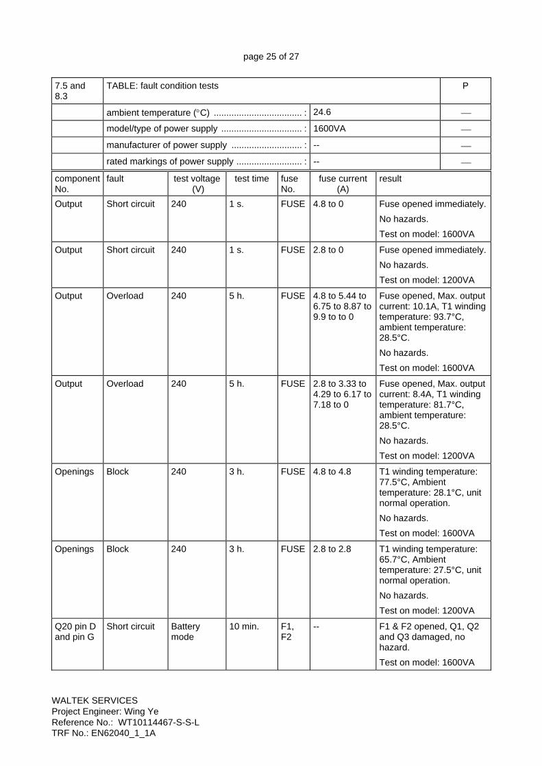
7.5 and 8.3
TABLE: fault condition tests P
ambient temperature (°C) ................................... : 24.6 ⎯
model/type of power supply ................................ : 1600VA ⎯
manufacturer of power supply ............................ : -- ⎯
rated markings of power supply .......................... : -- ⎯ component No.
fault test voltage (V)
test time fuse No.
fuse current (A)
result
Output Short circuit 240 1 s. FUSE 4.8 to 0 Fuse opened immediately. No hazards. Test on model: 1600VA
Output Short circuit 240 1 s. FUSE 2.8 to 0 Fuse opened immediately. No hazards. Test on model: 1200VA
Output Overload 240 5 h. FUSE 4.8 to 5.44 to 6.75 to 8.87 to 9.9 to to 0
Fuse opened, Max. output current: 10.1A, T1 winding temperature: 93.7°C, ambient temperature: 28.5°C. No hazards. Test on model: 1600VA
Output Overload 240 5 h. FUSE 2.8 to 3.33 to 4.29 to 6.17 to 7.18 to 0
Fuse opened, Max. output current: 8.4A, T1 winding temperature: 81.7°C, ambient temperature: 28.5°C. No hazards. Test on model: 1200VA
Openings Block 240 3 h. FUSE 4.8 to 4.8 T1 winding temperature: 77.5°C, Ambient temperature: 28.1°C, unit normal operation. No hazards. Test on model: 1600VA
Openings Block 240 3 h. FUSE 2.8 to 2.8 T1 winding temperature: 65.7°C, Ambient temperature: 27.5°C, unit normal operation. No hazards. Test on model: 1200VA
Q20 pin D and pin G
Short circuit Battery mode
10 min. F1, F2
-- F1 & F2 opened, Q1, Q2 and Q3 damaged, no hazard. Test on model: 1600VA

page 26 of 27
WALTEK SERVICES Project Engineer: Wing Ye Reference No.: WT10114467-S-S-L TRF No.: EN62040_1_1A
component No.
fault test voltage (V)
test time fuse No.
fuse current (A)
result
Q23 pin D and pin S
Short circuit Battery mode
10 min. F1, F2
-- F1 & F2 opened, Q1, Q2 and Q3 damaged, no hazard. Test on model: 1600VA
Q23 pin S and pin G
Short circuit Battery mode
10 min. F1, F2
-- Unit shutdown immediately, recoverable after the fault removed. No hazards. Test on model: 1600VA
C18 Short circuit 240 10 min. FUSE 4.8 to 1.3 to 0 Normal operation, F1, F2 opened. Discharge mode invalidation. No hazards.
Remark: 1) In charging mode ; 2) In discharging mode 7.7 TABLE A: maximum temperatures P
test voltage (V) ......................... AC198 AC254 Battery discharge ⎯
tamb1 (°C) ................................... See below See below See below ⎯
tamb2 (°C) ................................... See below See below See below ⎯ maximum temperature T of part/at::
T(oC) Measureed
T(oC) Measureed
T(oC) Measureed
allowed dTmax (oC)
Model: 1600VA
1. Input AC Socket 46.8 47 38.6 80
2. Internal wire 57.8 54.6 99.7 105
3. Fuse box 52.1 48.8 40.1 80
4. Transformer coil 83.1 80.5 77.8 110
5. Transformer core 80.2 78.4 70.5 110
6. CT1 coil 63.4 62.6 53.6 110
7. CT1 core 63.7 62.8 52.9 110
8. Relay J1 body 73.2 71.4 67.6 90
9. C24 body 58.6 57.4 53.8 105
10. C15 body 75.2 73.9 69.8 105
11. PCB under 20 59.7 59.4 125 130
12. PCB under Q10 63.3 62.4 128.9 130
13. C18 near R57 58.8 58.7 112.5 105
14. C19 near R65 56.9 56.7 112.4 105
15. Battery near Q2 51.6 52.2 58.6 80
16. Output AC Socket 48.8 48.5 41.3 80
17. Metal enclosure outside 40.2 40.6 53.8 70
18. Front enclosure inside 35.2 35.7 35.2 95

page 27 of 27
WALTEK SERVICES Project Engineer: Wing Ye Reference No.: WT10114467-S-S-L TRF No.: EN62040_1_1A
maximum temperature T of part/at::
T(oC) Measureed
T(oC) Measureed
T(oC) Measureed
allowed dTmax (oC)
19. Front enclosure outside 31.1 31.6 31.2 95
20. Ambient 28.2 29.1 28 --
Model: 1200VA
1. Input AC Socket 45.4 42.4 26.9 80
2. Internal wire 56.0 46.6 51.7 105
3. Fuse box 51.2 47.8 26.4 80
4. Transformer coil 68.3 62.6 52.1 110
5. Transformer core 64.7 58.2 28.7 110
6. CT1 coil 52.4 48.1 29 110
7. CT1 core 53.6 49.1 28.8 110
8. Relay J1 body 65.7 58.8 30.7 90
9. C24 body 49.3 45.8 29.3 105
10. C15 body 67.5 63.8 35.7 105
11. PCB under 20 52.1 49.0 102.9 130
12. PCB under Q10 53.1 50.1 82.2 130
13. C18 near R57 52.7 49.6 57.9 105
14. C19 near R65 50.9 48.0 58.1 105
15. Battery near Q2 46.3 43.2 30.5 80
16. Output AC Socket 40.6 38.6 26.8 80
17. Metal enclosure outside 37.5 35.6 37.5 70
18. Front enclosure inside 34.2 33.4 31.6 95
19. Front enclosure outside 31.3 30.8 26.3 95
20. Ambient 27.3 26.8 25 -- 7.7 TABLE B: ball pressure test of thermoplastic parts P
allowed impression diameter (mm) ..................... : ≤ 2 mm ⎯ part test temperature
(°C) impression diameter
(mm)
Bobbin of transformer 125 0.8
CN1 125 0.7
----------------------------------END----------------------------------

Page 1 of 5
ATTACHMENT- Photo Documentation
WALTEK SERVICES Project Engineer: Wing Ye Reference No.: WT10114467-S-S-L
Photo 1 View:
front
rear
right side
left side
top
bottom
internal All models
Photo 2 View:
front
rear
right side
left side
top
bottom
internal All models

Page 2 of 5
ATTACHMENT- Photo Documentation
WALTEK SERVICES Project Engineer: Wing Ye Reference No.: WT10114467-S-S-L
Photo 3 View:
front
rear
right side
left side
top
bottom
internal Model: 1600VA
Photo 3 View:
front
rear
right side
left side
top
bottom
internal Model: 1200VA

Page 3 of 5
ATTACHMENT- Photo Documentation
WALTEK SERVICES Project Engineer: Wing Ye Reference No.: WT10114467-S-S-L
Photo 4 View:
front
rear
right side
left side
top
bottom
internal All models
Photo 5 View:
front
rear
right side
left side
top
bottom
internal All models

Page 4 of 5
ATTACHMENT- Photo Documentation
WALTEK SERVICES Project Engineer: Wing Ye Reference No.: WT10114467-S-S-L
Photo 6 View:
front
rear
right side
left side
top
bottom
internal All models
Photo 7 View:
front
rear
right side
left side
top
bottom
internal All models

Page 5 of 5
ATTACHMENT- Photo Documentation
WALTEK SERVICES Project Engineer: Wing Ye Reference No.: WT10114467-S-S-L
Photo 8 View:
front
rear
right side
left side
top
bottom
internal All models