type z16 - armaturygroup.cz · disc ring 13cr or stellite or ptfe, nbr spring 51crv4 (1.8159)...
TRANSCRIPT
www.armatur ygroup.cz12
TYPE Z16LIFT CHECK VALVES
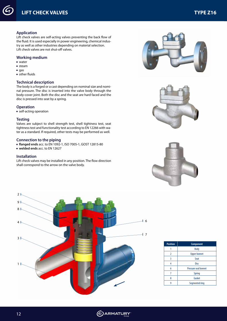
ApplicationLift check valves are self-acting valves preventing the back flow of the fluid. It is used especially in power engineering, chemical indus-try as well as other industries depending on material selection.Lift check valves are not shut-off valves.
Working medium water steam gas other fluids
Technical descriptionThe body is a forged or a cast depending on nominal size and nomi-nal pressure. The disc is inserted into the valve body through the body-cover joint. Both the disc and the seat are hard faced and the disc is pressed into seat by a spring.
Operation self-acting operation
TestingValves are subject to shell strength test, shell tightness test, seat tightness test and functionality test according to EN 12266 with wa-ter as a standard. If required, other tests may be performed as well.
Connection to the piping flanged ends acc. to EN 1092-1, ISO 7005-1, GOST 12815-80 welded ends acc. to EN 12627
InstallationLift check valves may be installed in any position. The flow direction shall correspond to the arrow on the valve body.
2
9
8
4
1
3
6
7
Position Component
1 Body
2 Upper bonnet
3 Seat
4 Disc
6 Pressure seal bonnet
7 Spring
8 Gasket
9 Segmented ring

www.armatur ygroup.czwww.armaturygroup.cz 13
LIFT CHECK VALVES WITH SPRING TYPE Z16
ComponentTmax 450 °C Tmax 530 °C Tmax 560 °C Tmax 450 °C Tmax 530 °C Tmax 560 °C
DN 15-40 DN 50-300
Body, bonnet P250GH (1.0460) 16Mo3 (1.5415) 13CrMo4-5 (1.7335) GP240GH (1.0619) G20Mo5 (1.5419) G17CrMo5-5 (1.7357)
Seat 13Cr or Stellite
Disc X30Cr13 (1.4028), X17CrNi16-2 (1.4057), P250GH (1.0460), 13CrMo4-5 (1.7335)
Disc ring 13Cr or Stellite or PTFE, NBR
Spring 51CrV4 (1.8159)
Packing rings, Gasket Graphite
Material - carbon and alloy design
60°
30° H
Dz
f
g
L
Dp
SGX15CrNiMn188
PTFE, NBR
Do
d
h
do × n
Dz
Dw
d
DN 15-50 DN 65-300
D1
D3
gf L
H
h
d
D2
dp d1
do x n
Welded ends
PN 16-40 • DN 15-300 • Tmax 560 °C (450 °C)
PN 16-40
DNFlanged ends Welded ends
PN 16 PN 40L g f H h kg *d1 *dp kg
D1 D3 D2 do x n D1 D3 D2 do x n 15 95 45 65 14 x 4 95 45 65 14 x 4 130 16 2 65 10 2,5 22 17 1,10 20 105 58 75 14 x 4 105 58 75 14 x 4 150 18 2 65 10 2,9 28 22 1,4 25 115 68 85 14 x 4 115 68 85 14 x 4 160 18 2 65 10 3,3 35 28,5 1,7 32 140 78 100 18 x 4 140 78 100 18 x 4 180 18 2 85 15 6,8 44 37 3,6 40 150 88 110 18 x 4 150 88 110 18 x 4 200 18 3 95 17 9,0 50 43 4,7 50 165 102 125 18 x 4 165 102 125 18 x 4 230 20 3 110 21 10,5 62 54 6,1
65 185 122 145 18 x 4 185 122 145 18 x 8 290 22 3 155 22 17,5 77 69 12,7
80 200 138 160 18 x 8 200 138 160 18 x 8 310 24 3 170 26 27,0 91 81 18,5 100 220 158 180 18 x 8 235 162 190 22 x 8 350 24 3 195 32 41,0 117 104 36,0 125 250 184 210 18 x 8 270 188 220 26 x 8 400 26 3 200 40 54,0 144 130,5 49,0 150 285 212 240 22 x 8 300 218 250 26 x 8 480 28 3 225 44 90,0 172 156,5 76,0 200 340 268 295 22 x 12 375 285 320 30 x 12 600 34 3 270 60 150,0 223 204,5 140,0 250 405 320 355 26 x 12 450 306 385 33 x 12 730 38 3 290 70 195,0 278 256,5 165,0 300 460 370 410 26 x 12 515 410 450 33 x16 850 42 3 410 130 360,0 329 306,5 280,0
Connection: EN 1092-1, ISO 7005-1, GOST 12815-80 FLANGED ENDS EN 12627 WELDED ENDS
60°
30° H
Dz
f
g
L
Dp
SGX15CrNiMn188
PTFE, NBR
Do
d
h
do × n
Dz
Dw
d
Tmax 200 °C„SW“
socket weld„G“
threaded ends
*These dimensions of welded ends may vary acc. to the specifications of customer orders.

www.armatur ygroup.cz14
LIFT CHECK VALVES WITH SPRING TYPE Z16
PN 63-100 • DN 15-200 • Tmax 560 °C (450 °C)
60°
30° H
Dz
f
g
L
Dp
SGX15CrNiMn188
PTFE, NBR
Do
d
h
do × n
Dz
Dw
d
DN 15-40 DN 50-200
ComponentTmax 450 °C Tmax 530 °C Tmax 560 °C Tmax 450 °C Tmax 530 °C Tmax 560 °C
DN 15-40 DN 50-200
Body, bonnet P250GH (1.0460) 16Mo3 (1.5415) 13CrMo4-5 (1.7335) GP240GH (1.0619) G20Mo5 (1.5419) G17CrMo5-5 (1.7357)Seat 13Cr or StelliteDisc X30Cr13 (1.4028), X17CrNi16-2 (1.4057), P250GH (1.0460), 13CrMo4-5 (1.7335)Disc ring 13Cr or Stellite or PTFE, NBRSpring 51CrV4 (1.8159)Gasket Graphite + Austenite
Material - carbon and alloy design
PN DN dFlanged ends Welded ends
D1 D3D2 do x n L g f H h kg *d1 *dp L kg
GOST EN GOST EN
63100
15 14 105 47 45 75 14 x 4 210 20 2 70 13 4,0 22 17 160 2,720 19 125 130 58 90 18 x 4 230 22 2 75 13 6,2 28 22 160 2,725 23 135 140 68 100 22 x 4 230 24 2 75 13 8,3 35 28,5 160 2,732 30 150 155 78 110 22 x 4 260 24 2 95 16 11,5 44 36,5 230 5,240 38 165 170 88 125 22 x 4 260 28 3 95 18 14,8 50 43 230 7,7
63
50 45 175 180 102 135 22 x 4 300 26 3 140 22 15,7 62 54 300 12,9
65 62 200 205 122 160 22 x 8 340 26 3 170 30 37,5 77 69 340 26,3
80 73 210 215 138 170 22 x 8 380 28 3 195 40 40,3 91 81 380 27,5100 94 250 162 200 22 x 8 430 30 3 200 55 54,0 117 104 430 37,2125 120 295 188 240 26 x 8 500 34 3 225 65 76,0 144 130,5 500 48,9150 144 340 345 212 218 290 33 x 8 550 36 3 300 70 151,0 172 156,5 550 101,1200 195 405 415 285 345 36 x 12 650 42 3 400 100 215,0 223 204,5 650 135,0
100
50 45 195 102 145 26 x 4 300 28 3 140 22 15,7 62 54 300 12,965 62 220 122 170 26 x 8 340 30 3 170 30 37,5 77 69 340 26,380 73 230 133 138 180 26 x 8 380 32 3 195 40 40,3 91 81 380 27,5
100 94 265 158 162 210 30 x 8 430 36 3 200 55 54,0 117 104 430 37,2125 120 310 315 184 188 250 33 x 8 500 40 3 225 65 76,0 144 127 500 48,9150 144 350 355 212 218 290 33 x 12 550 44 3 300 70 151,0 172 154 550 101,1200 195 430 285 360 36 x 12 650 52 3 400 100 215,0 223 199,5 650 135,0
D1
D3
gf L
H
h
d
D2
dp d1
do x n
Welded ends
60°
30° H
Dz
f
g
L
Dp
SGX15CrNiMn188
PTFE, NBR
Do
d
h
do × n
Dz
Dw
d
Tmax 200 °C„SW“
socket weld„G“
threaded ends
Connection: EN 1092-1, ISO 7005-1, GOST 12815-80 FLANGED ENDS EN 12627 WELDED ENDS
*These dimensions of welded ends may vary acc. to the specifications of customer orders.

www.armatur ygroup.czwww.armaturygroup.cz 15
LIFT CHECK VALVES WITH SPRING TYPE Z16
PN 160 • DN 15-200 • Tmax 560 °C (450 °C)
L
H
Dz
Dp
f
g
d
h
60°
30°
do × ndDo
Dz
Dw
DN 15-40 DN 50-200
ComponentTmax 450 °C Tmax 530 °C Tmax 560 °C Tmax 450 °C Tmax 530 °C Tmax 560 °C
DN 15-40 DN 50-200
Body, bonnet P250GH (1.0460) 16Mo3 (1.5415) 13CrMo4-5 (1.7335) GP240GH (1.0619) G20Mo5 (1.5419) G17CrMo5-5 (1.7357)
Seat 13Cr or Stellite
Disc X30Cr13 (1.4028), X17CrNi16-2 (1.4057), P250GH (1.0460), 13CrMo4-5 (1.7335)
Disc ring 13Cr or Stellite or PTFE, NBR
Spring 51CrV4 (1.8159)
Gasket Graphite + Austenite
Material - carbon and alloy design
PN 160
DN d
Flanged ends Welded ends
D1 D3D2 do x n L g f H h kg *d1 *dp L kg
GOST EN GOST EN
15 14 105 47 45 75 14 x 4 210 20 2 70 13 4,0 22 17 160 2,7
20 19 125 130 58 90 18 x 4 230 22 2 75 13 6,2 28 21 160 2,7
25 23 135 140 68 100 18 x 4 230 24 2 75 13 8,3 35 27 160 2,7
32 30 150 155 78 110 22 x 4 260 24 2 95 16 11,5 44 34,5 230 5,2
40 38 165 170 88 125 22 x 4 260 28 3 95 18 14,8 50 43 230 7,7
50 45 195 102 145 26 x 4 300 30 3 140 22 15,7 62 52,5 300 12,9
65 62 220 122 170 26 x 8 340 34 3 170 30 37,5 77 65 340 26,3
80 73 230 133 138 180 26 x 8 380 36 3 195 40 40,3 91 76,5 380 27,5
100 94 265 158 162 210 30 x 8 430 40 3 200 55 54,0 117 98,5 430 37,2
125 120 310 315 184 188 250 33 x 8 500 44 3 225 95 76,0 144 120,5 500 48,9
150 144 350 355 212 218 290 33 x 12 550 50 3 300 100 151,0 172 144,5 550 101,1
200 190 430 285 360 36 x 12 650 60 3 400 110 210,0 223 192 650 145,0
D1
D3
gf L
H
h
d
D2
dp d1
do x n
Welded ends
Connection: EN 1092-1, ISO 7005-1, GOST 12815-80 FLANGED ENDS EN 12627 WELDED ENDS
L
H
Dz
Dp
f
g
d
h
60°
30°
do × ndDo
Dz
Dw
„SW“ socket weld
„G“ threaded ends
*These dimensions of welded ends may vary acc. to the specifications of customer orders.

www.armatur ygroup.cz16
LIFT CHECK VALVES WITH SPRING TYPE Z16
PN 250-400 • DN 15-125 • Tmax 600 °C (450 °C)
Component Tmax 450 °C Tmax 530 °C Tmax 560 °C Tmax 570 °C Tmax 600 °C Body, bonnet P250GH (1.0460) 16Mo3 (1.5415) 13CrMo4-5 (1.7335) 14MoV6-3 (1.7715) 11CrMo9-10 (1.7383)Seat VT9 or 13Cr or Stellite Disc X20Cr13 (1.4021), P250GH (1.0460)Disc ring 13Cr or Stellite Packing rings, gasket Graphite + Austenitic steel
Connection: EN 1092-1, ISO 7005-1 FLANGED ENDS EN 12627 WELDED ENDS
DN Welded ends/ Standard
H h Flanged ends
d *d1 *dp L kgD1
D3 D2
do x n L g
f kg PN 250 PN 320 PN 250 PN 320 PN 250 PN 320
15 14 22 15,0 160 4 235 15 130 45 90 18 x 4 230 26 2 8,720 20 28 19,0 160 4 240 15 150 58 105 22 x 4 260 28 30 2 11,325 24 35 24,0 160 4 240 15 150 160 68 105 115 22 x 4 260 28 34 2 13,332 30 44 31,5 300 15 365 27 - - - - - / 300* - - -40 38 50 36,0 300 15 365 27 185 195 88 135 145 26 x 4 300 34 38 3 30,250 48 62 / 77* 45,0 300 15 365 27 200 210 102 150 160 26 x 8 350 38 42 3 3265 62 77 / 91* 59,5 340 26,5 450 30 230 255 122 180 200 26/30* x 8 400 42 51 3 57,880 76 117 81,0 380 55,5 580 40 255 275 138 200 220 30 x 8 450 46 55 3 93
100 92 144 102,0 430 71 620 55 300 335 162 235 265 33/36* x 8 520 54 65 3 138,5125 112 172 120,5 500 91 670 65 340 380 188 275 310 33/36* x 12 600 60 75 3 186,9
* is valid for PN 320
DN 15-25 DN 32-125
L
Dw
Dz
Dp
H
L
h
d
Dz
Dp
f g
L
Dz
g
Dp
do x n
Do
45° 30°
H
Dw
Dz
Dp
L
45°
d
h
30°
f
d1 d1
D1 D1
D3 D3
dp dp
L
LL
L
h
h
h
h
gd
df
H H
H H
do x n
do x n
D2 D2
welded ends
„SW“socket
weldflanged ends
Material - carbon and alloy design
PN 250-320
Welded ends H h
DN d *d1 *dp L kg 15 14 28 17 160 4,00 135 15 20 20 35 21,5 160 4,00 140 15 25 24 44 29 160 4,00 140 15 32 30 50 33 300 15,00 245 27 40 38 62 40 300 15,00 245 27 50 44 77 49,5 300 15,00 245 27 65 62 91 62 340 26,50 270 30 80 76 117 81 380 55,50 320 40
100 92 144 102 430 71,00 390 55 125 112 172 126,5 500 91,00 420 65
PN 400
*These dimensions of welded ends may vary acc. to the specifications of customer orders.
www.armatur ygroup.czwww.armaturygroup.cz 17
STAINLESS STEEL LIFT CHECK VALVES WITH SPRING TYPE Z16
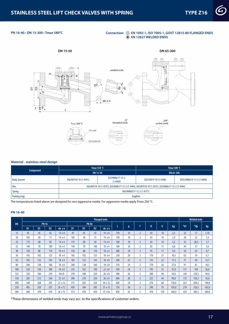
ComponentTmax 550 °C Tmax 500 °C
DN 15-50 DN 65-300
Body, bonnet X6CrNiTi18-10 (1.4541)X2CrNiMo17-12-2
(1.4404)GX5CrNi19-10 (1.4308) GX5CrNiMo19-11-2 (1.4408)
Disc X6CrNiTi18-10 (1.4541), X2CrNiMo17-12-2 (1.4404), X6CrNiTi18-10 (1.4541), X2CrNiMo17-12-2 (1.4404)
Spring X6CrNiMoTi17-12-2 (1.4571)
Packing rings Graphite
Material - stainless steel design
60°
30° H
Dz
f
g
L
Dp
SGX15CrNiMn188
PTFE, NBR
Do
d
h
do × n
Dz
Dw
d
DN 15-50 DN 65-300
D1
D3
gf L
H
h
d
D2
dp d1
do x n
60°
30° H
Dz
f
g
L
Dp
SGX15CrNiMn188
PTFE, NBR
Do
d
h
do × n
Dz
Dw
d
Tmax 200 °C„SW“
socket weld„G“
threaded ends
welded ends
PN 16-40 • DN 15-300 • Tmax 580°C
PN 16-40
DNFlanged ends Welded ends
PN 16 PN 40L g f H h kg *d1 *dp kg
D1 D3 D2 do x n D1 D3 D2 do x n 15 95 45 65 14 x 4 95 45 65 14 x 4 130 16 2 65 10 2,5 22 17 1,10 20 105 58 75 14 x 4 105 58 75 14 x 4 150 18 2 65 10 2,9 28 22 1,4 25 115 68 85 14 x 4 115 68 85 14 x 4 160 18 2 65 10 3,3 35 28,5 1,7 32 140 78 100 18 x 4 140 78 100 18 x 4 180 18 2 85 15 6,8 44 37 3,6 40 150 88 110 18 x 4 150 88 110 18 x 4 200 18 3 95 17 9,0 50 43 4,7 50 165 102 125 18 x 4 165 102 125 18 x 4 230 20 3 110 21 10,5 62 54 6,1
65 185 122 145 18 x 4 185 122 145 18 x 8 290 22 3 155 22 17,5 77 69 12,7
80 200 138 160 18 x 8 200 138 160 18 x 8 310 24 3 170 26 27,0 91 81 18,5 100 220 158 180 18 x 8 235 162 190 22 x 8 350 24 3 195 32 41,0 117 104 36,0 125 250 184 210 18 x 8 270 188 220 26 x 8 400 26 3 200 40 54,0 144 130,5 49,0 150 285 212 240 22 x 8 300 218 250 26 x 8 480 28 3 225 44 90,0 172 156,5 76,0 200 340 268 295 22 x 12 375 285 320 30 x 12 600 34 3 270 60 150,0 223 204,5 140,0 250 405 320 355 26 x 12 450 306 385 33 x 12 730 38 3 290 70 195,0 278 256,5 165,0 300 460 370 410 26 x 12 515 410 450 33 x16 850 42 3 410 130 360,0 329 306,5 280,0
The temperatures listed above are designed for non-aggressive media. For aggressive media apply Tmax 250 °C.
Connection: EN 1092-1, ISO 7005-1, GOST 12815-80 FLANGED ENDS EN 12627 WELDED ENDS
*These dimensions of welded ends may vary acc. to the specifications of customer orders.

www.armatur ygroup.cz18
STAINLESS STEEL LIFT CHECK VALVES WITH SPRING TYPE Z16
PN 63-100 • DN 15-200 • Tmax 580 °C
60°
30° H
Dz
f
g
L
Dp
SGX15CrNiMn188
PTFE, NBR
Do
d
h
do × n
Dz
Dw
d
DN 15-40 DN 50-200
D N dFlanged ends Welded ends
D1 D3D2 do x n L g f H h kg *d1 *dp L kg
GOST EN GOST EN15 14 105 105 47 45 75 14 x 4 210 20 2 70 13 4,0 22 17 160 2,720 19 125 130 58 58 90 18 x 4 230 22 2 75 13 6,2 28 22 160 2,725 23 135 140 68 68 100 22 x 4 230 24 2 75 13 8,3 35 28,5 160 2,732 30 150 155 78 78 110 22 x 4 260 24 2 95 16 11,5 44 36,5 230 5,240 38 165 170 88 88 125 22 x 4 260 28 3 95 18 14,8 50 43 230 7,750 45 175 180 102 102 135 22 x 4 300 26 3 140 22 15,7 62 54 300 12,965 62 200 205 122 122 160 22 x 8 340 26 3 170 30 37,5 77 69 340 26,380 73 210 215 138 138 170 22 x 8 380 28 3 195 40 40,3 91 81 380 27,5
100 94 250 250 162 162 200 22 x 8 430 30 3 200 55 54,0 117 104 430 37,2125 120 295 295 188 188 240 26 x 8 500 34 3 225 65 76,0 144 130,5 500 48,9150 144 340 345 212 218 290 33 x 8 550 36 3 300 70 151,0 172 156,5 550 101,1200 195 405 415 285 285 345 36 x 12 650 42 3 400 100 215,0 223 204,5 650 135,0
D N dFlanged ends Welded ends
D1 D3D2 do x n L g f H h kg *d1 *dp L kg
GOST EN GOST EN15 14 105 105 47 45 75 14 x 4 210 20 2 70 13 4,0 22 17 160 2,720 19 125 130 58 58 90 18 x 4 230 22 2 75 13 6,2 28 21,5 160 2,725 23 135 140 68 68 100 22 x 4 230 24 2 75 13 8,3 35 28,5 160 2,732 30 150 155 78 78 110 22 x 4 260 24 2 95 16 11,5 44 36 230 5,240 38 165 170 88 88 125 22 x 4 260 28 3 95 18 14,8 50 43 230 7,750 45 175 180 102 102 135 22 x 4 300 26 3 140 22 15,7 62 54 300 12,965 62 200 205 122 122 160 22 x 8 340 26 3 170 30 37,5 77 69 340 26,380 73 210 215 138 138 170 22 x 8 380 28 3 195 40 40,3 91 81 380 27,5
100 94 250 250 162 162 200 22 x 8 430 30 3 200 55 54,0 117 104 430 37,2125 120 295 295 188 188 240 26 x 8 500 34 3 225 65 76,0 144 127 500 48,9150 144 340 345 212 218 290 33 x 8 550 36 3 300 70 151,0 172 154 550 101,1200 195 405 415 285 285 345 36 x 12 650 42 3 400 100 215,0 223 199,5 650 135,0
D1
D3
gf L
H
h
d
D2
dp d1
do x n
60°
30° H
Dz
f
g
L
Dp
SGX15CrNiMn188
PTFE, NBR
Do
d
h
do × n
Dz
Dw
d Tmax 200 °C
„SW“ socket weld
„G“threaded ends
welded ends
ComponentTmax 550 °C Tmax 500 °C
DN 15-50 DN 65-300
Body, bonnet X6CrNiTi18-10 (1.4541)X2CrNiMo17-12-2
(1.4404)GX5CrNi19-10 (1.4308) GX5CrNiMo19-11-2 (1.4408)
Disc X6CrNiTi18-10 (1.4541), X2CrNiMo17-12-2 (1.4404), X6CrNiTi18-10 (1.4541), X2CrNiMo17-12-2 (1.4404)Spring X6CrNiMoTi17-12-2 (1.4571)Packing rings Graphite
Material - stainless steel design
PN 63
PN 100
The temperatures listed above are designed for non-aggressive media. For aggressive media apply Tmax 250 °C.
Connection: EN 1092-1, ISO 7005-1, GOST 12815-80 FLANGED ENDS EN 12627 WELDED ENDS
*These dimensions of welded ends may vary acc. to the specifications of customer orders.

www.armatur ygroup.czwww.armaturygroup.cz 19
D N dFlanged ends Welded ends
D1 D3D2 do x n L g f H h kg d1* *dp L kg
GOST EN GOST EN15 14 105 105 47 45 75 14 x 4 210 20 2 70 13 4,0 22 17 160 2,720 19 125 130 58 58 90 18 x 4 230 22 2 75 13 6,2 28 22 160 2,725 23 135 140 68 68 100 22 x 4 230 24 2 75 13 8,3 35 28,5 160 2,732 30 150 155 78 78 110 22 x 4 260 24 2 95 16 11,5 44 36,5 230 5,240 38 165 170 88 88 125 22 x 4 260 28 3 95 18 14,8 50 43 230 7,750 45 175 180 102 102 135 22 x 4 300 26 3 140 22 15,7 62 54 300 12,965 62 200 205 122 122 160 22 x 8 340 26 3 170 30 37,5 77 69 340 26,380 73 210 215 138 138 170 22 x 8 380 28 3 195 40 40,3 91 81 380 27,5
100 94 250 250 162 162 200 22 x 8 430 30 3 200 55 54,0 117 104 430 37,2125 120 295 295 188 188 240 26 x 8 500 34 3 225 65 76,0 144 130,5 500 48,9150 144 340 345 212 218 290 33 x 8 550 36 3 300 70 151,0 172 156,5 550 101,1200 195 405 415 285 285 345 36 x 12 650 42 3 400 100 215,0 223 204,5 650 135,0
STAINLESS STEEL LIFT CHECK VALVES WITH SPRING TYPE Z16
PN 160 • DN 15-200 • Tmax 580 °C
L
H
Dz
Dp
f
g
d
h
60°
30°
do × ndDo
Dz
Dw
DN 15-40 DN 50-200
D1
D3
gf L
H
h
d
D2
dp d1
do x n
L
H
Dz
Dp
f
g
d
h
60°
30°
do × n
dDo
Dz
Dw
„SW“ socket weld
„G“threaded ends
welded ends
PN 160
ComponentTmax 550 °C Tmax 500 °C
DN 15-50 DN 65-300
Body, bonnet X6CrNiTi18-10 (1.4541)X2CrNiMo17-12-2
(1.4404)GX5CrNi19-10 (1.4308) GX5CrNiMo19-11-2 (1.4408)
Disc X6CrNiTi18-10 (1.4541), X2CrNiMo17-12-2 (1.4404), X6CrNiTi18-10 (1.4541), X2CrNiMo17-12-2 (1.4404)
Spring X6CrNiMoTi17-12-2 (1.4571)
Packing rings Graphite
Material - stainless steel design
The temperatures listed above are designed for non-aggressive media. For aggressive media apply Tmax 250 °C.
Connection: EN 1092-1, ISO 7005-1, GOST 12815-80 FLANGED ENDS EN 12627 WELDED ENDS
Connection: EN 1092-1, ISO 7005-1, GOST 12815-80 FLANGED ENDS EN 12627 WELDED ENDS
*These dimensions of welded ends may vary acc. to the specifications of customer orders.
www.armatur ygroup.cz20
DN 15-25 DN 32-125
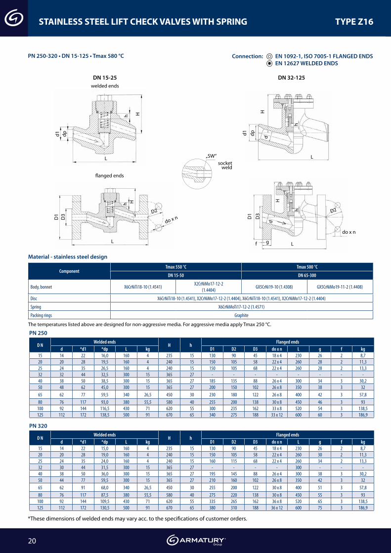
PN 250-320 • DN 15-125 • Tmax 580 °C
STAINLESS STEEL LIFT CHECK VALVES WITH SPRING TYPE Z16
L
Dw
Dz
Dp
H
L
h
d
Dz
Dp
f g
L
Dz
g
Dp
do x n
Do
45° 30°
H
Dw
Dz
Dp
L
45°
d
h
30°
f
d1 d1
D1 D1
D3 D3
dp dp
L
L L
L
h
h
h
h
g
dd
f
H H
H H
do x n
do x n
D2 D2
welded ends
„SW“socket
weld
flanged ends
ComponentTmax 550 °C Tmax 500 °C
DN 15-50 DN 65-300
Body, bonnet X6CrNiTi18-10 (1.4541)X2CrNiMo17-12-2
(1.4404)GX5CrNi19-10 (1.4308) GX5CrNiMo19-11-2 (1.4408)
Disc X6CrNiTi18-10 (1.4541), X2CrNiMo17-12-2 (1.4404), X6CrNiTi18-10 (1.4541), X2CrNiMo17-12-2 (1.4404)
Spring X6CrNiMoTi17-12-2 (1.4571)
Packing rings Graphite
Material - stainless steel design
The temperatures listed above are designed for non-aggressive media. For aggressive media apply Tmax 250 °C.
D NWelded ends
H hFlanged ends
d *d1 *dp L kg D1 D2 D3 do x n L g f kg15 14 22 16,0 160 4 235 15 130 90 45 18 x 4 230 26 2 8,720 20 28 19,5 160 4 240 15 150 105 58 22 x 4 260 28 2 11,325 24 35 26,5 160 4 240 15 150 105 68 22 x 4 260 28 2 13,332 32 44 32,5 300 15 365 27 - - - - - - - -40 38 50 38,5 300 15 365 27 185 135 88 26 x 4 300 34 3 30,250 48 62 45,0 300 15 365 27 200 150 102 26 x 8 350 38 3 3265 62 77 59,5 340 26,5 450 30 230 180 122 26 x 8 400 42 3 57,880 76 117 93,0 380 55,5 580 40 255 200 138 30 x 8 450 46 3 93
100 92 144 116,5 430 71 620 55 300 235 162 33 x 8 520 54 3 138,5125 112 172 138,5 500 91 670 65 340 275 188 33 x 12 600 60 3 186,9
D NWelded ends
H hFlanged ends
d *d1 *dp L kg D1 D2 D3 do x n L g f kg15 14 22 15,0 160 4 235 15 130 90 45 18 x 4 230 26 2 8,720 20 28 19,0 160 4 240 15 150 105 58 22 x 4 260 30 2 11,325 24 35 24,0 160 4 240 15 160 115 68 22 x 4 260 34 2 13,332 30 44 31,5 300 15 365 27 - - - - 300 - - -40 38 50 36,0 300 15 365 27 195 145 88 26 x 4 300 38 3 30,250 44 77 59,5 300 15 365 27 210 160 102 26 x 8 350 42 3 3265 62 91 68,0 340 26,5 450 30 255 200 122 30 x 8 400 51 3 57,880 76 117 87,5 380 55,5 580 40 275 220 138 30 x 8 450 55 3 93
100 92 144 109,5 430 71 620 55 335 265 162 36 x 8 520 65 3 138,5125 112 172 130,5 500 91 670 65 380 310 188 36 x 12 600 75 3 186,9
PN 250
PN 320
Connection: EN 1092-1, ISO 7005-1 FLANGED ENDS EN 12627 WELDED ENDS
*These dimensions of welded ends may vary acc. to the specifications of customer orders.