tytan furnace system - 4d labs · the fcs10 microprocessor-based control system provides a central...
TRANSCRIPT

4D LABS, Simon Fraser University, 8888 University Drive, Burnaby, B.C., V5A 1S6
E [email protected] T 778.782.8158 F 778.782.3765 W www.4dlabs.ca
TYTAN Furnace System
Standard Operating Procedure
Revision: 1.0 — Last Updated: August 2018 by Hadi Esmaeilsabzali
Purpose
This document provides a detailed operation procedure of the TYTAN Furnace System at 4D LABS.
Formal training is required for all users prior to using the system.
Revision History
# Revised by: Date Modification
1 Hadi Esmaeilsabzali Nov 2018 Initial Release
2
3
4
5

2
4D LABS, Simon Fraser University, 8888 University Drive, Burnaby, B.C., V5A 1S6
E [email protected] T 778.782.8158 F 778.782.3765 W www.4dlabs.ca
Table of Contents
Purpose ................................................................................................................................................... 1
Revision History ........................................................................................................................................ 1
Table of Contents ..................................................................................................................................... 2
Abbreviations ........................................................................................................................................... 3
Overview of the TYTAN Furnace System .................................................................................................... 3
FCS10 Tube Control System ...................................................................................................................... 5
Function Groups and Commands .......................................................................................................... 5
FCS10 Touchscreen GUI ....................................................................................................................... 6
Recipes ................................................................................................................................................ 9
General Recipe Structure .................................................................................................................. 9
Tube 1: Pyrogenic Wet and Dry Oxidation ....................................................................................... 10
Tube 2: n-Type Doping ................................................................................................................... 11
Tube 3: Silicon Nitride LPCVD......................................................................................................... 12
Tube 4: Polysilicon LPCVD .............................................................................................................. 14
Creating a New Recipe and Editing an Existing Recipe .................................................................... 16
Modifying a Running Process Recipe .............................................................................................. 19
Operation .............................................................................................................................................. 19
Running a Recipe ............................................................................................................................... 19
Wafer Loading ................................................................................................................................... 20
Wafer Unloading ................................................................................................................................ 20
Appendix 1: Function Groups and Commands ......................................................................................... 21
Appendix 2: FCS10 Alarms List ............................................................................................................... 22
References and Files ............................................................................................................................... 24
Contact Information ............................................................................................................................... 24

3
4D LABS, Simon Fraser University, 8888 University Drive, Burnaby, B.C., V5A 1S6
E [email protected] T 778.782.8158 F 778.782.3765 W www.4dlabs.ca
Abbreviations
LPCVD: Low pressure chemical vapor deposition
TCU: Temperature control unit
MFC: Mass flow controller
GUI: Graphical user interface
Overview of the TYTAN Furnace System
The TYTAN furnace system manufactured by TYSTAR Corporation (Fig. 1) is composed of four tubes (Tubes
1-4, top to bottom) that provide the following capabilities:
a) Pyrogenic wet and dry oxidation (Tube 1)
b) n-type (phosphorous) doping (Tube 2)
c) Ultra-low stress and stoichiometric silicon nitride LPCVD (Tube 3)
d) Doped and undoped polysilicon LPCVD (Tube 4)
Fig. 1. The TYTAN furnace system

4
4D LABS, Simon Fraser University, 8888 University Drive, Burnaby, B.C., V5A 1S6
E [email protected] T 778.782.8158 F 778.782.3765 W www.4dlabs.ca
Fig. 2 illustrates an overall configuration of the system and its major components. Each tube is operated
independently and controlled via process recipes that are executed by the tube’s designated FCS10 control
system. A process essentially consists of a sequential series of timed steps. Each step involves programmed
temperature settings, gas flows, boat loader movements, and other signal inputs and outputs.
All four FCS10 control systems (one for each tube) are interfaced with and can be managed by a host com-
puter through the DCS30 software. While all of the FCS10 capabilities are accessible through the host
computer and the DCS30 software, the host computer is mainly used for uploading and downloading reci-
pes, downloading system configuration information, saving process logs, and accessing and calibrating
TCUs. Users can largely operate the furnace system using only the FCS10 control system, which allows cre-
ating/editing recipes and running processes. Therefore, unless exclusively trained by the tool owner, users
are normally advised NOT to operate the system using the host computer. Users should contact the tool
owner if they need to use the host computer for uploading new recipes, changing configuration files, or
troubleshooting. Since the FCS10 control system is the main interface between users and the furnace sys-
tem, it is explained in more detail in the next section.
Fig. 2. Illustration of the overall configuration of the TYTAN furnace system

5
4D LABS, Simon Fraser University, 8888 University Drive, Burnaby, B.C., V5A 1S6
E [email protected] T 778.782.8158 F 778.782.3765 W www.4dlabs.ca
FCS10 Tube Control System
The FCS10 microprocessor-based control system provides a central point to control and monitor a furnace
tube and its corresponding hardware devices (e.g., TCU, MFC, and boat loader) through various in-
put/output signals that are programmed in process recipes. By controlling output signals (i.e. process pa-
rameters) defined in recipes, FCS10 adjusts the environment within the tube, determining the characteris-
tics of the produced thin film/wafer. By monitoring input signals (e.g., contact closure states, signal levels,
or equipment status) from hardware devices, FCS10 makes decisions as to the acceptability of process run
conditions. Under certain conditions, such as power failure, hardware malfunction, etc., FCS10 causes the
process to exit the normal processing sequence and follow fault responses that are coded in process recipe.
Process recipes are stored in the FCS10 memory; however, the number of recipes that can be stored in this
memory is limited. As such, a library of all recipes should normally be stored in the host computer, from
which the required recipes are loaded to the FCS10 memory as needed. Each FCS10 control system has a
touchscreen interface (see Fig. 3) that allows users to operate the corresponding tube by editing recipes
and running processes.
Function Groups and Commands
Users can interact with the FCS10 control system via a series of functions (or commands). Due to the large
number of available functions, it is impractical to display all choices in one menu. As such, these functions
are sorted into 9 logical groups known as function groups that are listed in Table 1. Each group and its
functions list can be accessed via a single-letter code on the FCS10 touchscreen. When a group is selected,
the available functions are listed below the existing main menu selections. Most of the function groups are
meant to be used for maintenance or troubleshooting purposes by the tool owner or advanced users. For
normal operation purposes, users need to be familiar with Recipe and Display function groups and the
functions associated with them. As it will be explained in the next sub-section, the most frequently used
functions are presented on the FCS10 GUI in the form of several tabs that support the majority of regular
operation needs. A comprehensive list of all function groups and the associate functions can be found in
Appendix 1 of this document. Note that each function within a given group is identified by a two-letter
6
4D LABS, Simon Fraser University, 8888 University Drive, Burnaby, B.C., V5A 1S6
E [email protected] T 778.782.8158 F 778.782.3765 W www.4dlabs.ca
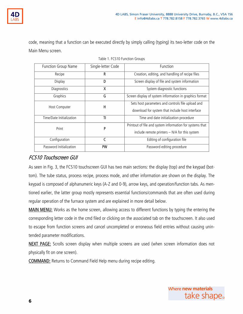
code, meaning that a function can be executed directly by simply calling (typing) its two-letter code on the
Main Menu screen.
Table 1. FCS10 Function Groups
Function Group Name Single-letter Code Function
Recipe R Creation, editing, and handling of recipe files
Display D Screen display of file and system information
Diagnostics X System diagnostic functions
Graphics G Screen display of system information in graphics format
Host Computer H Sets host parameters and controls file upload and
download for system that include host interface
Time/Date Initialization TI Time and date initialization procedure
Print P Printout of file and system information for systems that
include remote printers – N/A for this system
Configuration C Editing of configuration file
Password Initialization PW Password editing procedure
FCS10 Touchscreen GUI
As seen in Fig. 3, the FCS10 touchscreen GUI has two main sections: the display (top) and the keypad (bot-
tom). The tube status, process recipe, process mode, and other information are shown on the display. The
keypad is composed of alphanumeric keys (A-Z and 0-9), arrow keys, and operation/function tabs. As men-
tioned earlier, the latter group mostly represents essential functions/commands that are often used during
regular operation of the furnace system and are explained in more detail below.
MAIN MENU: Works as the home screen, allowing access to different functions by typing the entering the
corresponding letter code in the cmd filed or clicking on the associated tab on the touchscreen. It also used
to escape from function screens and cancel uncompleted or erroneous field entries without causing unin-
tended parameter modifications.
NEXT PAGE: Scrolls screen display when multiple screens are used (when screen information does not
physically fit on one screen).
COMMAND: Returns to Command Field Help menu during recipe editing.

7
4D LABS, Simon Fraser University, 8888 University Drive, Burnaby, B.C., V5A 1S6
E [email protected] T 778.782.8158 F 778.782.3765 W www.4dlabs.ca
DISPLAY DIR.: It provides a listing of all the recipes stored in the FCS10 memory. Once stored in the
memory, recipe information (recipe name, date created, number of steps, memory used by the recipe, and
current recipe status) appears on the directory display until they are deleted from the FCS10 system.
DISPLAY STATUS: Shows a current report of process parameters during a process run.
DISPLAY RECIPE: Provides detailed information about a given recipe. For any recipe stored in the FCS10
memory, this function provides step summaries, step details, global tolerance and fault responses, and
global equipment failure responses. After accessing this function by clicking on DISPLAY RECIPE, use Lssss
to view steps details staring at step ssss (if only L is entered, the display starts with the IDLE step) or Sssss
to view step summary of step ssss (if only S is entered, the display starts with the IDLE step).
DISPLAY EQUIP: Shows a list of possible sources of equipment error and equipment status for an ongoing
process run. Also shows the current step, elapsed step time, and step time to go.
RUN: Initiates the process run sequence once a process recipe is loaded.
EVENT: Used in process control as a conditional input signal (e.g., to acknowledge the completion of a
step in the process and force it to proceed to the next step).
HOLD: Puts a process run on manual hold and process clocks are not advanced. When the Run key is
pressed again, the process exits the HOLD state and resumes the execution of the step.
DISPLAY HISTORY: All alarms occurring during each process run are stored in memory as a process history.
Alarms include process step changes, conditional branches, tolerance violations, equipment errors, etc. The
start of a new process run clears the history of the last process. Process histories are also uploaded and
stored in the host computer for later analysis.
RECIPE LOAD: Before a process run can be initiated, the appropriate recipe must be loaded. After clicking
RECIPE LOAD, all recipes in the FCS10 memory are displayed. When the recipe load function is selected, a
small pointer appears inside the blinking cursor. Use the arrow keys to position the cursor to the left of the
recipe you wish to select. The small pointer should be pointing to the recipe name. Press the Enter key
twice to select the recipe. When recipes are loaded, they are checked for configuration incompatibilities. A
screen appears informing you of the results of the error check. Recipes cannot be loaded until errors are
resolved. If no errors are detected, the data for any variable (VAR) parameters must be specified. After any
VAR parameters are defined, the recipe is loaded and ready for the process run.

8
4D LABS, Simon Fraser University, 8888 University Drive, Burnaby, B.C., V5A 1S6
E [email protected] T 778.782.8158 F 778.782.3765 W www.4dlabs.ca
Fig. 3. The FCS10 touchscreen user interface
BACKSPACE: Used to delete characters when needed.
RECIPE MODIFY: Used to temporally modify parameters of a process that is currently active. Note that
modifying current process parameters acts as a manual override and does not interfere with the ongoing
process run.
LOAD IN: Signals the boat loader to load the boat/wafers into the tube.
LOAD OUT: Signals the boat loader to unload the boat/wafers from the tube.
RECIPE DELETE: Used to remove a recipe from the file directory on the FCS10 memory. Once this function
has been performed, the recipe is permanently erased from the FCS10 memory.
ON: Sets a parameter to the ON value.
OFF: Sets a parameter to the OFF value.
ALRM ACK: Acknowledges and cancels the display of alarms. Alarms appear at the bottom line of the dis-
play and may be either informative (e.g., identifying the current step of the process run) or cautionary (e.g.,

9
4D LABS, Simon Fraser University, 8888 University Drive, Burnaby, B.C., V5A 1S6
E [email protected] T 778.782.8158 F 778.782.3765 W www.4dlabs.ca
warning you that values are out of tolerance). Alarms are stored in a history file that are saved on the host
computer and can serve as a tool for analyzing process run errors. A comprehensive list of alarms is pre-
sented in Appendix 2. Acknowledge all alarms after they have been noted so that any subsequent alarms
can be displayed.
ABORT: Terminates the normal processing at any time during the process run. When this function is called,
the process jumps immediately to the first step of the ABRT sequence. After the steps of the ABRT se-
quence are executed, the process reverts to the IDLE state. Note that the ABRT sequence cannot be abort-
ed or put on hold.
ENTER: Used to enter characters or fields of information. Keypad entries are not registered until the Enter
key is pressed.
CLEAR: Erases current character entry.
Note that in order to guard against unauthorized use of certain functions, some of the functions, most no-
table of which RECIPE DELETE, RECIPE MODIFY, and RECIPE EDIT (RE), are password-protected. These
functions cannot be accessed without first entering the correct password for that function. Users receive
the required password information during the training.
Recipes
Process recipes are programs that define the function of system hardware during a process run. Recipes
consist of a series of timed steps with programmed set points, tolerance, gas flows, temperature levels,
boat loader movements, etc. specified for each step. Recipes also define the conditional branches taken in
response to certain signal inputs, equipment failures, and errors. Recipes can be created locally on the
FCS10 system or remotely on the host computer.
General Recipe Structure
Generally, recipes have two main components: a) the process routine and b) the equipment/power failure
response. The first component mainly specifies a tube’s environment (i.e. temperatures and gas flows) that
in turn defines the characteristics of the thin film/wafer produced at the end of the process. The STRT step
is always the first step executed in any recipe. This step normally runs for the duration specified in the reci-
pe. After the STRT step is complete, steps are executed sequentially for the duration specified in the pro-

10
4D LABS, Simon Fraser University, 8888 University Drive, Burnaby, B.C., V5A 1S6
E [email protected] T 778.782.8158 F 778.782.3765 W www.4dlabs.ca
cess recipe. During each timed step, the functions of system hardware are controlled by signal outputs from
the FCS10 control system. An alarm is generated whenever a new step is executed. Under normal condi-
tions, the process ends after the last recipe step is executed. After the execution of the last step, the pro-
cess reverts to the IDLE step. Since no step time is associated with the IDLE step, the process remains in
IDLE until acted on by the operator. An alarm is generated when the process ends.
The second component of a recipe defines the system response to any equipment and/or power failure dur-
ing the process. Any major fluctuation (drop, surge, and outage) in the furnace power supply or failure of
any of the hardware devices could severely affect the process run. To safeguard against such failures, gen-
eral conditional branch structures must be included in all recipes to respond to these conditions. The details
of different equipment/power failure responses are not discussed in this document as all recipe templates
that are used to create new recipes already include such a component.
More specific recipe details for each of the four tubes are discussed next. Such information should help us-
ers better understand each process and design their process parameters.
Tube 1: Pyrogenic Wet and Dry Oxidation
Generally, a typical dry oxidation process involves ramping up and stabilizing the temperature (typically
1100 ºC), growing oxide for a set period of time at the given temperature, and ramping down the temper-
ature. Accordingly, a dry oxidation recipe would have the steps shown in Table 2.
Table 2. A template for dry oxidation process recipe
Step
Name Function Duration (hh:mm:ss)
IDLE Idle state 00:00:00
STRT Boat is open 00:15:00
LDWF Loading wafers 00:30:00
BTIN Boat moving in 00:15:00
STB1 Stabilizing the temperature 00:20:00
RMPU Ramping up the temperature 01:00:00
STB2 Stabilizing the temperature 00:02:00

11
4D LABS, Simon Fraser University, 8888 University Drive, Burnaby, B.C., V5A 1S6
E [email protected] T 778.782.8158 F 778.782.3765 W www.4dlabs.ca
DRYO Oxide growth 00:43:00 (100 nm oxdie)
ANEL Annealing 00:30:00
RMPD Ramping down the temperature 02:00:00
HLD1 Hold the process – waiting for unloading the boat 00:00:00
BTOT Boat moving out 00:15:00
ULWF Unloading wafers 00:30:00
BIN2 Boat moving in 00:15:00
ENDP End of process 00:00:10
Note that the expected thickness oxide after 43 minutes is ~100 nm. Several oxide calculator tools1 are
available online and can be used to adjust the duration of the DRYO step. Tube 1 is also capable of wet
oxidation or wet/dry oxidation in which the oxide is grown in the presence of both oxygen and hydrogen.
The process recipe is almost similar expect that it also includes a controlled flow of hydrogen into the tube.
Normally, the wet oxide growth is significantly faster that than the dry oxide growth.
Tube 2: n-Type Doping
Similar to the oxidation process, the doping process also generally includes ramping up and stabilizing the
temperature, performing doping at the given temperature, and slowly ramping down the temperature.
While the furnace system at 4D LABS is equipped with and can potentially use gaseous POCl3, it is current-
ly using solid phosphorous source for doping. The latter method is significantly safer while provides con-
sistent doping results. The source is typically kept inside the tub. In order to use a new source and used
source that has been left outside the furnace, it has to be properly annealed. Please contact the tool owner
if you need to change the source. Table 3 details the steps of a typical doping process.
Table 3. A template for n-type doping process recipe
Step
Name Function Duration (hh:mm:ss)
IDLE Idle state 00:00:00
1 https://cleanroom.byu.edu/OxideTimeCalc

12
4D LABS, Simon Fraser University, 8888 University Drive, Burnaby, B.C., V5A 1S6
E [email protected] T 778.782.8158 F 778.782.3765 W www.4dlabs.ca
STRT Boat is open 00:15:00
005 Loading wafers 00:15:00
BTIN Boat moving in 00:15:00
015 Stabilizing the temperature at 750 ºC 00:10:00
025 Ramping up the temperature to 1000 ºC 01:00:00
STB1 Stabilizing the temperature 00:02:00
ANL1 Diffusion 01:00:00
033 Ramping down the temperature 02:00:00
HLD1 Hold the process – waiting for unloading the boat 00:00:00
BTOT Boat moving out 00:15:00
040 Unloading wafers 00:30:00
045 Boat moving in 00:15:00
050 End of process 00:00:30
Tube 3: Silicon Nitride LPCVD
Unlike the previous processes that take place at the atmospheric pressure, the nitride deposition is an
LPCVD process, meaning that the deposition is performed at pressures as low as 10-50 mTorr. Therefore, a
typical nitride deposition process involves pumping down the tube to achieve the required pressure while
maintaining a certain flow of ammonia and dichlorosilane gases, which at a given temperature results in
silicon nitride deposition on the wafer. To achieve a proper vacuum in the tube before the deposition and
get rid of all toxic gases after the deposition, a series of pump/purge and leak check steps should be car-
ried out during the process. A detailed sequence of steps is shown in Table 4 below.
Table 4. A template for silicon nitride LPCVD process recipe
Step
Name Function Duration (hh:mm:ss)
IDLE Idle state 00:00:00
STRT Boat is open/N2 backfill running 00:30:00

13
4D LABS, Simon Fraser University, 8888 University Drive, Burnaby, B.C., V5A 1S6
E [email protected] T 778.782.8158 F 778.782.3765 W www.4dlabs.ca
BOUT Boat moving out 00:15:00
LDWF Loading wafers 00:20:00
BTIN Boat moving in 00:15:00
PMP1 Pumping down the tube 00:08:00
CHKP Check the pressure 00:05:00
PUR1 Pump/Purge 00:10:00
PMP2 Pumping down the tube 00:05:00
PUR2 Pump/Purge 00:10:00
PMP3 Pumping down the tube 00:05:00
PUR3 Pump/Purge 00:10:00
PMP4 Pumping down the tube 00:05:00
PUR4 Pump/Purge 00:10:00
PMP5 Pumping down the tube 00:10:00
LCHK Leak Check 00:02:00
PMP6 Pumping down the tube 00:01:00
STB1 Stabilizing the temperature 01:00:00
PNH3 Turn ON NH3 00:03:00
PDCS Turn ON DCS 00:02:00
DEPO Deposition 00:46:00
DCSP Turn OFF DCS 00:05:00
NH3P Turn OFF NH3 00:10:00
PUR6 Pump/Purge 00:10:00
PMP7 Pumping down the tube 00:05:00
PUR7 Pump/Purge 00:10:00
PMP8 Pumping down the tube 00:03:00
PUR8 Pump/Purge 00:08:00
PMP9 Pumping down the tube 00:05:00

14
4D LABS, Simon Fraser University, 8888 University Drive, Burnaby, B.C., V5A 1S6
E [email protected] T 778.782.8158 F 778.782.3765 W www.4dlabs.ca
PUR9 Pump/Purge 00:10:00
PM10 Pumping down the tube 00:05:00
PU10 Pump/Purge 00:10:00
HLD1 Hold the process – waiting for unloading the boat 00:00:00
BKF1 Slow backfill 00:02:00
BKF2 Slow backfill 00:02:00
BKF3 Slow backfill 00:02:00
BKF4 Slow backfill 00:02:00
BKF5 Slow backfill 00:02:00
BTOT Boat moving out 00:15:00
UNLD Unloading wafers 00:20:00
LDIN Boat moving in 00:15:00
PIDL Pump standby 00:10:00
ENDP End process 00:05:00
Tube 4: Polysilicon LPCVD
Similar to nitride deposition, the polysilicon deposition is also an LPCVD process that is performed at very
low pressures maintained by a controlled flow of silane (and nitrogen). Table 5 shows the steps of a typical
polysilicon LPCVD process.
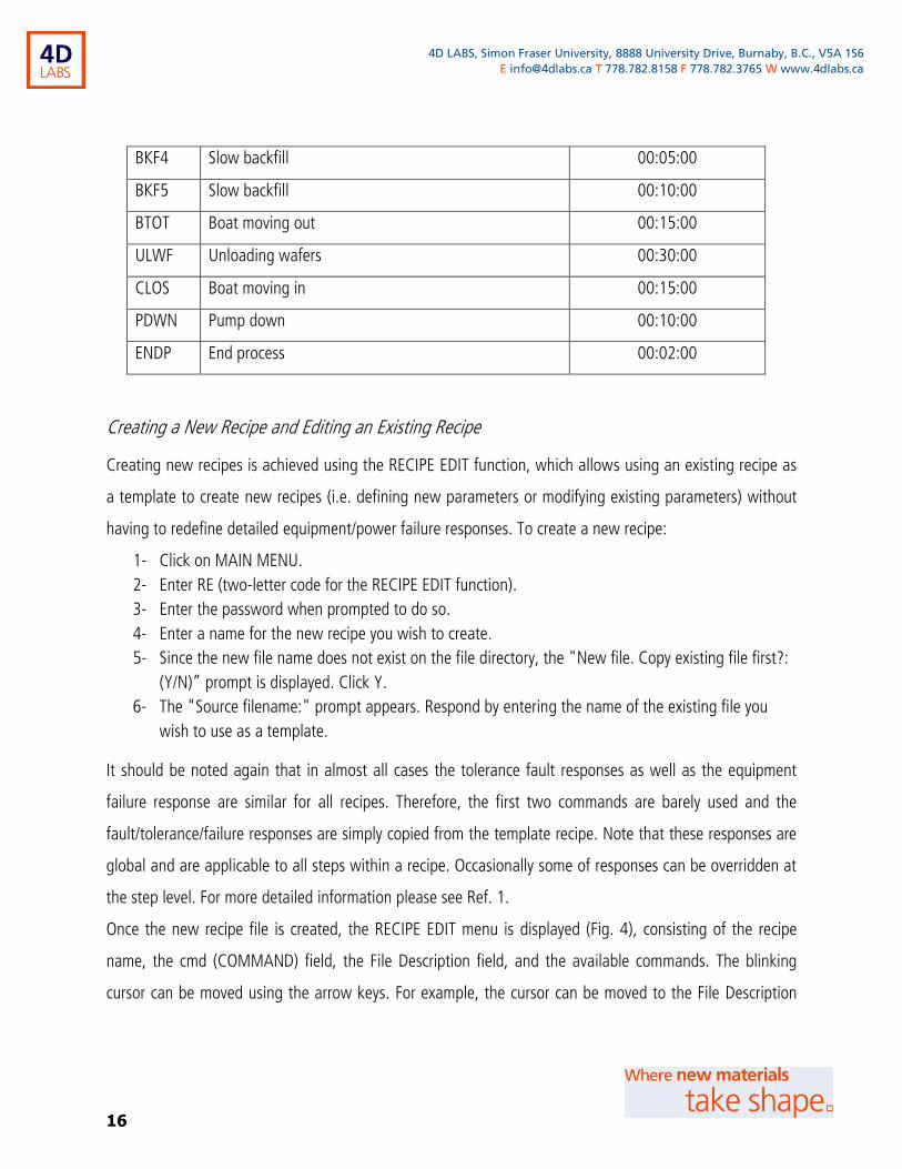
Table 5. A template for silicon nitride LPCVD process recipe
Step
Name Function Duration (hh:mm:ss)
IDLE Idle state 00:00:00
STRT Boat is open/N2 backfill running 00:30:00
BOUT Boat moving out 00:15:00
LDWF Loading wafers 00:15:00
BTIN Boat moving in 00:15:00

15
4D LABS, Simon Fraser University, 8888 University Drive, Burnaby, B.C., V5A 1S6
E [email protected] T 778.782.8158 F 778.782.3765 W www.4dlabs.ca
STB1 Stabilizing the temperature (550) 00:05:00
VACC Vacuum check 00:01:00
TEMP Variable Temps 00:03:00
PUMP2 Pumping down the tube 00:05:00
PUR2 Pump/Purge 00:10:00
PMP3 Pumping down the tube 00:05:00
PUR3 Pump/Purge 00:05:00
PMP4 Pumping down the tube 00:10:00
LKCH Leak check 00:02:00
VACP Vacuum pump 00:02:00
STBP Stabilizing the pressure 00:02:00
TMPC Temperature check 00:01:00
PSIH Turn ON SiH4 00:01:00
DEPO Deposition 01:00:00
PMPP Pumping out gases 00:03:00
PMP5 Pumping down the tube 00:05:00
PUR5 Pump/Purge 00:10:00
PMP6 Pumping down the tube 00:05:00
PUR6 Pump/Purge 00:10:00
PMP7 Pumping down the tube 00:05:00
PUR7 Pump/Purge 00:10:00
PMP8 Pumping down the tube 00:05:00
STB2 Stabilizing the pressure 00:01:00
HLD1 Hold the process – waiting for unloading the boat 00:00:00
BKF1 Slow backfill 00:02:00
BKF2 Slow backfill 00:05:00
BKF3 Slow backfill 00:05:00
16
4D LABS, Simon Fraser University, 8888 University Drive, Burnaby, B.C., V5A 1S6
E [email protected] T 778.782.8158 F 778.782.3765 W www.4dlabs.ca
BKF4 Slow backfill 00:05:00
BKF5 Slow backfill 00:10:00
BTOT Boat moving out 00:15:00
ULWF Unloading wafers 00:30:00
CLOS Boat moving in 00:15:00
PDWN Pump down 00:10:00
ENDP End process 00:02:00
Creating a New Recipe and Editing an Existing Recipe
Creating new recipes is achieved using the RECIPE EDIT function, which allows using an existing recipe as
a template to create new recipes (i.e. defining new parameters or modifying existing parameters) without
having to redefine detailed equipment/power failure responses. To create a new recipe:
1- Click on MAIN MENU.
2- Enter RE (two-letter code for the RECIPE EDIT function).
3- Enter the password when prompted to do so.
4- Enter a name for the new recipe you wish to create.
5- Since the new file name does not exist on the file directory, the "New file. Copy existing file first?:
(Y/N)” prompt is displayed. Click Y.
6- The "Source filename:" prompt appears. Respond by entering the name of the existing file you
wish to use as a template.
It should be noted again that in almost all cases the tolerance fault responses as well as the equipment
failure response are similar for all recipes. Therefore, the first two commands are barely used and the
fault/tolerance/failure responses are simply copied from the template recipe. Note that these responses are
global and are applicable to all steps within a recipe. Occasionally some of responses can be overridden at
the step level. For more detailed information please see Ref. 1.
Once the new recipe file is created, the RECIPE EDIT menu is displayed (Fig. 4), consisting of the recipe
name, the cmd (COMMAND) field, the File Description field, and the available commands. The blinking
cursor can be moved using the arrow keys. For example, the cursor can be moved to the File Description

17
4D LABS, Simon Fraser University, 8888 University Drive, Burnaby, B.C., V5A 1S6
E [email protected] T 778.782.8158 F 778.782.3765 W www.4dlabs.ca
filed, where a brief summary of the recipe can be entered. Use arrow keys to move the cursor back to the
cmd field. Alternatively click on the COMMAND tab to return to the cmd field.
Fig. 4. The RECIPE EDIT Menu
The available commands to edit a recipe are listed in Table 6 below:
Table 6. Recipe Edit Menu Commands
Command Description
TF Used for programming default tolerance and fault responses (effective throughout the process run)
EF Used for programming responses to equipment failure (effective throughout the process run)
G Accesses current recipe step
Gssss Accesses a specified step. Replace ssss with the step name.
Issss Inserts a new step after an existing step. Replace ssss with the name of the existing step that the
new step will follow. For example, to insert a step after the STRT step, enter ISTRT.
Issss.nnnn Inserts a new step after an existing step with the ssss.nnnn name format. For example, to insert a
step after STRT+0001, enter ISTRT.0001.

18
4D LABS, Simon Fraser University, 8888 University Drive, Burnaby, B.C., V5A 1S6
E [email protected] T 778.782.8158 F 778.782.3765 W www.4dlabs.ca
DELssss Deletes a step. For example, to delete a step named DEMO, enter DELDEMO.
DELssss.nnnn Deletes steps with the ssss.nnnn name format. To delete step STRT+0004, enter DELSTRT.0004.
H Accesses the help screen
In order to edit step-specific parameters within a recipe, the Gssss command can be used to access a par-
ticular step where the parameter is to be set. Typing the “SP” command in the cmd field then allows modi-
fying parameters. The cursor can then be moved to the field associated with the parameters and they can
be modified. Alternatively, once can start from the very first step (the STRT step) by typing GSTRT and then
typing N to move to subsequent steps of the recipe. Some step names are set and cannot be modified by
the user. These step names are IDLE, STRT, SHLD, and ABRT. If steps in the run or abort sequences are not
given a label, they are referred to as the last defined step label plus a corresponding number. For example,
the third step in the run sequence after the STRT step would be referred to as STRT+0003. In order to in-
sert a new step, the Issss or Issss.nnnn commands can be used.
Each step of a recipe has a parameter called Step Time, which determines the duration of the step. The
maximum allowable step time is 99 hours, 59 minutes, and 59 seconds (99:59:59). If zero is programmed
as the step time, this means there is no time limit for the step. Steps with no time limit must have condi-
tional branches included to signal the end of the step. Otherwise, the step will continue indefinitely.
Within some steps, there are some set-points that are signal levels programmed in each step. If there is no
change in a signal level from the last step, you may enter NC (no change) as the set-point. Set-points must
be within the minimum and maximum range defined in the configuration. Note that for gas flow values,
the MFS460 has separate parameters defining valve status (ON/OFF) and flow level. Programming the min-
imum set-point for the MFS flow level also programs the valve to be OFF. Programming MFS set-points
above the minimum also programs the valve to be ON. If set-points are not programmed, the default val-
ues are the minimum and off.
In addition to creating new recipes, as the name suggests, the RECIPE EDIT function can be also used to
modify an existing recipe. The process is very similar to creating a new recipe, except that when prompted
to enter the recipe name, the name of the existing recipe that is to be edited should be entered. Note that
recipe editing should not be attempted during an ongoing process run.

19
4D LABS, Simon Fraser University, 8888 University Drive, Burnaby, B.C., V5A 1S6
E [email protected] T 778.782.8158 F 778.782.3765 W www.4dlabs.ca
Modifying a Running Process Recipe
Occasionally, it is necessary to temporarily modify recipe parameters while the process is running without
permanently modifying the recipe. This can be using by executing the RECIPE MODIFY (RM) function. The
RM function does not change the permanent recipe stored in memory. This function is used to modify pa-
rameters of a process that is currently active. Note that modifying current process parameters acts as a
manual override, and does not interfere with the ongoing process run. The RECIPE MODIFY function can be
used to temporality change step times, gas flows, and other process parameters, as follows:
1- Go to MAIN MENU.
2- Enter RM (Alternatively the RECIPE MODIFY function can be called by clicking on the RECIPE MOD-
IFY tab on the screen).
3- Enter the password when prompted to do so.
4- Use arrow keys to move the cursor to desired fields.
5- Change the desired value
6- Go to MAIN MENU
Operation
Before a process recipe is loaded, the system is in STANDBY condition. During STANDBY, all signals are
OFF and zero. Before running a recipe, the appropriate process recipe should be loaded using the RECIPE
LOAD function discussed earlier. Once the recipe has been loaded, the process will be in the IDLE step.
During this step, signals are sent to system hardware to prepare the tube for the process run. No step time
is associated with the IDLE step, so the process remains in IDLE until the process run is initiated by pressing
the RUN key. An alarm is generated when the run begins.
Running a Recipe
Before a process run can be initiated, the appropriate recipe must be loaded first.
1- Go to MAIN MENU.
2- Enter RL (Alternatively the RECIPE LOAD function can be called by clicking on the RECIPE LOAD
tab on the screen).
3- When the RECIPE LOAD function is selected, a small pointer appears inside the blinking cursor.
Use the arrow keys to position the cursor to the left of the recipe you wish to select. The small
pointer should be pointing to the recipe name.

20
4D LABS, Simon Fraser University, 8888 University Drive, Burnaby, B.C., V5A 1S6
E [email protected] T 778.782.8158 F 778.782.3765 W www.4dlabs.ca
4- Press the Enter key twice to select -the recipe. When recipes are loaded, they are checked for IF -
GOTO reference errors and configuration incompatibilities. A screen appears informing you of the
results of the error check. Recipes cannot be loaded until errors are resolved.
Wafer Loading
Once a recipe is run, it goes through a number of steps before the boat is opened. In order to load your
sample, wait until the boat is fully opened, at which point an alarm goes off indicating that the step is fin-
ished (i.e. the boat is fully open). Using the pickup tool, carefully pick the quartz boat and place it on the
bench on a piece of glass. Using a dedicated furnace tweezer, place your wafer on the desired slot(s) on
the quartz boat. The best practice is to fill the central slots and use dummy wafers to occupy the rest if you
are not processing enough wafers to fill all the slots on a boat. For example, if you are processing one wa-
fer only, the best practice is to place it on slot position 12 or 13 (central slots) and use (tube-dedicated)
dummy wafers for the remaining slots.
After placing your wafer(s) on the quartz boat, use the pickup tool again to place the boat on the cantile-
vers. The distance between the buffer surface and the boat centre should be 8.5”.
NOTE: Make sure that your wafer is RCA1/RCA2/BOE cleaned. Before loading your wafer perform a quick
(30 sec) BOE dip to remove the native oxide.
Wafer Unloading
Following the completion of the deposition/oxidation steps, the process enters and remains on the HOLD
step until an input (EVENT) is received from the operator. Once this input is registered, the boat moves out.
Wait until the boat is fully open. Then use the pickup tool to carefully pick the quartz boat and place it on a
piece of glass on the bench. After removing your wafers, put the quartz boat back on the cantilevers and
close the boat.

21
4D LABS, Simon Fraser University, 8888 University Drive, Burnaby, B.C., V5A 1S6
E [email protected] T 778.782.8158 F 778.782.3765 W www.4dlabs.ca
Appendix 1: Function Groups and Commands
FCS10 function groups, the associated commands, and their codes are shown below. Each group can be
accessed and a list of its commands can be viewed on the FCS10 GUI by typing its single-letter code on the
command line on the Main Menu screen. Individual commands can also be directly called by typing their
codes on the Main Menu screen.

22
4D LABS, Simon Fraser University, 8888 University Drive, Burnaby, B.C., V5A 1S6
E [email protected] T 778.782.8158 F 778.782.3765 W www.4dlabs.ca
Appendix 2: FCS10 Alarms List
A list of FCS10 alarms is presented, including alarms codes, description, explanation, and possible required
action. Alarms are appeared at the bottom of the display and have the following format:
Code Description Explanation/Required Action
81011000 MFS1 1/0 ERROR Communication not established with MFC1/Acknowledge and verify connection
82012000 MFS2 1/0-ERROR Communication not established with MFC2/Acknowledge and verify connection
83013000 TCU 1/0 ERROR Communication not established with TCU/Acknowledge and verify connection
84014000 BTL 1/0 ERROR Communication not established with boat loader/Acknowledge and verify connection
85011000 MFS1 IN MANUAL MFC1 is in manual mode
86012000 MFS2 IN MANUAL MFC2 is in manual mode
87013000 TCU IN MANUAL Occurs during calibration of backup thermocouples
01011000 MFS1 I/0 OK Communication with MFC1 is established/Acknowledge
02012000 MFS2 I/0 OK Communication with MFC2 is established/Acknowledge
03013000 TCU 1/0 OK Communication with TCU is established/Acknowledge
04014000 BTL I/O OK Communication with boat loader is established/Acknowledge
05011000 MFS1 IN AUTO MFC1 ready for process run/Acknowledge
06012000 MFS2 IN AUTO MFC2 ready for process run/Acknowledge
07013000 TCU IN AUTO TCU ready for process run
91011000 MFS1 FAULT Display equipment status (DE) to identify fault
92012000 MFS2 FAULT Display equipment status (DE) to identify fault
93013000 TCU FAULT Occurs when transformer switch is off or tripped/Turn on transformer switch
94014000 BTL FAULT Occurs when boat loader switch is off/Turn on boat loader
11011000 LMFS1 NO FAULT MFC1 has returned to normal status
12012000 MFS2 NO FAULT MFC2 has returned to normal status

23
4D LABS, Simon Fraser University, 8888 University Drive, Burnaby, B.C., V5A 1S6
E [email protected] T 778.782.8158 F 778.782.3765 W www.4dlabs.ca
13013000 TCU NO FAULT TCU has returned to normal status
14014000 BTL NO FAULT Boat loader has returned to normal status
01020000 POWER UP System is on - occurs during initial activation and after configuration changes have been
made
02020000 POWER FAIL Power outage has occurred
01030000 PROCESS START Process run has been initiated
04030207 PROCESS END Process run has ended
05030000 PROCESS ABORT Process run has been terminated
06030000 PROCESS HOLD Process run has been placed on hold
07030000 PROCESS CONTINUE Process run is continuing
09034040 PROCESS LOADED Recipe load is complete
10030000 PRCS, FMC DATA
ERROR
Process error has occurred/Power outage is less than set-point. Change power outage set-
point
14030000 PWRFL 10 HRS Power down has lasted more than 10 hours
15030000 NEW STEP New process run step has started
01053012 SIGID * HIGH TEMPLC is above tolerance/Bring TEMPLC within tolerance
02053015 SIGID * OK TEMPS is within tolerance
03053012 SIGID * LOW TEMPLC is below tolerance/Bring TEMPLC within tolerance
01063011 IF SIGID * HI TEMPL is above tolerance/Bring TEMPL within tolerance
03061012 IF SIGID * LO TEMPL is below tolerance/Bring TEMPL within tolerance
06061041 IF SIGID * OFF DNTLK switch is not energized
07060300 IF SIGID ON Process has been manually sent to another step - occurs when Event key is pressed.
06061041 IF
PROC.EQUIPT.FAILURE Equipment failure has occurred
08061002 TEMP/PRES INTER-
LOCK Low interlock temperature

24
4D LABS, Simon Fraser University, 8888 University Drive, Burnaby, B.C., V5A 1S6
E [email protected] T 778.782.8158 F 778.782.3765 W www.4dlabs.ca
References and Files
1- FCS10 Operation Manual, TYSTAR Corporation
Contact Information
Questions or comments in regard to this document should be directed towards Hadi Esmaeilsabzali (sab-
[email protected]) in 4D LABS at Simon Fraser University, Burnaby, BC, Canada.