u-charge rt battery module user's guide - mrbill's web site · pdf fileu-charge®...
TRANSCRIPT
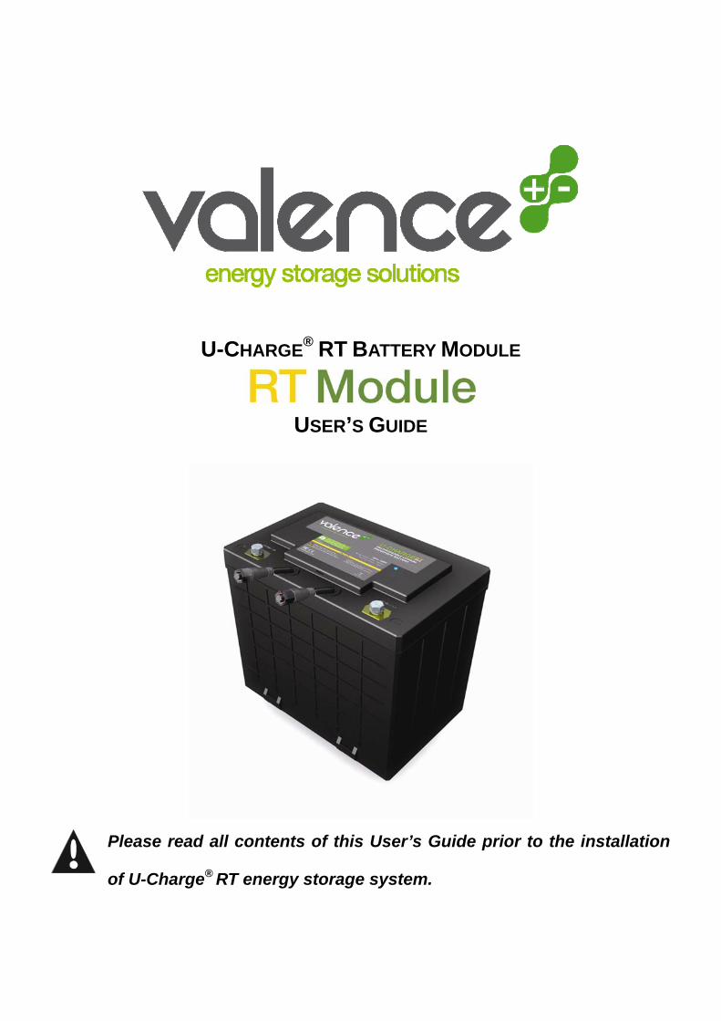
U-CHARGE® RT BATTERY MODULE
USER’S GUIDE
Please read all contents of this User’s Guide prior to the installation
of U-Charge® RT energy storage system.

Performance may vary depending on, but not limited to cell usage and application. If cell is used outside specifications, performance will diminish. All specifications are subject to change without notice. All information provided herein is believed, but not guaranteed, to be current and accurate. Copyright © 2005-2008 Valence Technology, Inc.
Revision Date October 2008
12303 Technology Blvd., Suite 950, Austin, TX 78727, USA Phone (888) VALENCE or +1 (512) 527-2900, Fax +1 (512) 527-2910 Unit 63 Mallusk Enterprise Park, Mallusk Drive, Newtownabbey, UK Phone +44(0) 28 9084 5400, Fax +44(0)28 9083 8912 Email: [email protected], Web site: www.valence.com
TABLE OF CONTENTS 1. CONTACT INFORMATION ..................................................................................................... 3 2. SAFETY INFORMATION........................................................................................................ 5
2.1 Internal Protection Features ...........................................................................................................6 3. BEFORE YOU START .......................................................................................................... 7
3.1 General information ........................................................................................................................7 Table 1: Shows charge voltage ratings for packs connected in 1, 2, 3 or 4 in series. ..............8
4. CONTENTS/TOOLS REQUIRED............................................................................................. 8 Table 2: Contents and tools required ................................................................................................8
5. Installation....................................................................................................................... 8 5.1 Tips .................................................................................................................................................8 5.2 Installation of U-Charge® RT Battery into a 12 V System ...............................................................9 5.3 Installation of up to 4 batteries in Series .......................................................................................10
Table 3: Pin-out of the RS-485 communication ports in U-Charge® RT power system................... 11 6. CHARGING THE BATTERIES ............................................................................................. 12
6.1 Select a Proper Battery Charger...................................................................................................12 6.2 Charging the Battery.....................................................................................................................12
7. U-CHARGE® RT POWER SYSTEM FEATURES ..................................................................... 13 7.1 Discharge Control .........................................................................................................................13 7.2 Charge Control .............................................................................................................................14 7.3 State Of Charge (SOC) Measurement ..........................................................................................14 7.4 Cell Balancing...............................................................................................................................14 7.5 U-Charge® RT Battery Specifications ...........................................................................................15
Table 4: Battery Specifications........................................................................................................15 Table 5: Self Discharge Rates ........................................................................................................15 Table 6: U-Charge® RT Specifications ............................................................................................16
8. BATTERY STATUS INDICATION ........................................................................................... 17 8.1 GREEN LED: Normal Operation...................................................................................................17 8.2 YELLOW LED: Indication .............................................................................................................17 8.3 RED LED: Fault Indication............................................................................................................18 8.4 No LED Indication: Severely Over Discharged .............................................................................18
9. TIPS FOR OPTIMIZING PERFORMANCE................................................................................. 18 10. MAINTENANCE AND STORAGE ......................................................................................... 19
10.1 Visual Inspection.........................................................................................................................19 10.2 Voltage Checking........................................................................................................................19 10.3 Battery Storage...........................................................................................................................19
Table 7: Recharge Guidelines.........................................................................................................19 10.4 Battery Serial Number ................................................................................................................20
11. TRANSPORTATION AND SHIPPING .................................................................................... 20 12. BATTERY OVERHEATING................................................................................................. 21
Performance may vary depending on, but not limited to cell usage and application. If cell is used outside specifications, performance will diminish. All specifications are subject to change without notice. All information provided herein is believed, but not guaranteed, to be current and accurate. Copyright © 2005-2008 Valence Technology, Inc.
Revision Date October 2008
12303 Technology Blvd., Suite 950, Austin, TX 78727, USA Phone (888) VALENCE or +1 (512) 527-2900, Fax +1 (512) 527-2910 Unit 63 Mallusk Enterprise Park, Mallusk Drive, Newtownabbey, UK Phone +44(0) 28 9084 5400, Fax +44(0)28 9083 8912 Email: [email protected], Web site: www.valence.com
13.1 Recycling ....................................................................................................................................22 14. USE IN LIFE SUPPORT APPLICATIONS .............................................................................. 23 15. LIMITED WARRANTY....................................................................................................... 23
Performance may vary depending on, but not limited to cell usage and application. If cell is used outside specifications, performance will diminish. All specifications are subject to change without notice. All information provided herein is believed, but not guaranteed, to be current and accurate. Copyright © 2005-2008 Valence Technology, Inc.
Revision Date October 2008
12303 Technology Blvd., Suite 950, Austin, TX 78727, USA Phone (888) VALENCE or +1 (512) 527-2900, Fax +1 (512) 527-2910 Unit 63 Mallusk Enterprise Park, Mallusk Drive, Newtownabbey, UK Phone +44(0) 28 9084 5400, Fax +44(0)28 9083 8912 Email: [email protected], Web site: www.valence.com
1. CONTACT INFORMATION Customer Support: 8 AM to 5 PM CST 1-888-VALENCE (USA Customers Only) 1-888-825-3623 For North America Support 1-888-825-3623 For European, Middle East, Africa, Asia, and Australia Support +44 (0)28 9084 5400 (N. Ireland) 9 AM to 5 PM GMT Sales: 1-888-825-3623 Fax: 1-512-527-2910 Sales Email: [email protected] Support Email: [email protected] Mailing Address USA: Valence Technology, Inc. 12303 Technology Blvd. Suite 950 Austin, Texas 78727 Mailing Address Europe: Unit 63 Mallusk Enterprise Park Mallusk Drive, Mallusk, Newtownabbey Co. Antrim, Northern Ireland BT36 4GN
Performance may vary depending on, but not limited to cell usage and application. If cell is used outside specifications, performance will diminish. All specifications are subject to change without notice. All information provided herein is believed, but not guaranteed, to be current and accurate. Copyright © 2005-2008 Valence Technology, Inc.
Revision Date October 2008
12303 Technology Blvd., Suite 950, Austin, TX 78727, USA Phone (888) VALENCE or +1 (512) 527-2900, Fax +1 (512) 527-2910 Unit 63 Mallusk Enterprise Park, Mallusk Drive, Newtownabbey, UK Phone +44(0) 28 9084 5400, Fax +44(0)28 9083 8912 Email: [email protected], Web site: www.valence.com
2. SAFETY INFORMATION The U-Charge® RT power system must be used in accordance with the manufacturer’s specifications and guidelines for recommended use. When used properly and in accordance with these instructions, the battery is a safe, reliable and convenient energy storage solution.
CAUTION: Misuse or abuse of the U-Charge® XP power system may result in personal injury or fire. .
• Keep all original packaging. International law dictates that the batteries are shipped under UN 3090, Class 9 rules for hazardous goods/ dangerous materials.
• Burn Hazard. • Abusive operation of the battery (e.g., overcharge, crush, puncture, excessive heat or
moisture) may produce smoke. In such an event, ventilate the area. • Extinguish any flames with copious amounts of water, use a carbon dioxide, dry-powder
fire extinguisher, or cover with sand or mud (therefore removing excess oxygen from the flame).
• DO NOT disassemble, crush, puncture, or incinerate. • DO NOT short circuit external contacts. • DO NOT expose to temperatures above 60ºC (140ºF). • NEVER charge the battery without charge protection circuitry and equipment approved by
Valence Technology. • Remove all jewelry or other metallic objects during the installation of the battery. • Exercise care in handling any charged battery, particularly when placing it inside a
container with metal objects. • DO NOT throw away the battery in the trash. • Dispose of the battery properly in accordance with local regulations. Visit the
Rechargeable Battery Recycling Corporation’s website at www.rbrc.com for more information.
• DO NOT use with other types of batteries connected in series or parallel with the U-Charge® RT power systems.

Performance may vary depending on, but not limited to cell usage and application. If cell is used outside specifications, performance will diminish. All specifications are subject to change without notice. All information provided herein is believed, but not guaranteed, to be current and accurate. Copyright © 2005-2008 Valence Technology, Inc.
Revision Date October 2008
12303 Technology Blvd., Suite 950, Austin, TX 78727, USA Phone (888) VALENCE or +1 (512) 527-2900, Fax +1 (512) 527-2910 Unit 63 Mallusk Enterprise Park, Mallusk Drive, Newtownabbey, UK Phone +44(0) 28 9084 5400, Fax +44(0)28 9083 8912 Email: [email protected], Web site: www.valence.com
Your battery may contain symbols, defined as follows:
Symbol Definition
Important safety information will follow.
Your battery should not be disposed of in a fire.
Your battery may require recycling in accordance with local laws. Contact your local regulatory authorities for more information. Do Not include battery with lead acid battery recycling.
Your battery should not be thrown in the trash.
Shock Hazard - Labels may be located on or inside the equipment to alert people that dangerous voltage may be present.
Burn Hazard - Labels may be located on or inside the equipment to alert people that surface temperatures may be dangerous.
2.1 Internal Protection Features The U-Charge® RT power system has several safety features built-in to help protect against abusive conditions:
• Valence Phosphate technology provides lithium-ion advantages of high energy, light weight, and long cycle life without the fear of thermal runaway under abuse conditions.
• Cell voltages and internal temperature monitored by each battery. • LED status lights on the battery gives visual indication of battery condition. • An optional Battery Discharge Indicator (U-BDI, part number 1002867) can be used for
remote wired visibility of the battery pack state of charge. Contact your dealer for information on how to purchase a U-BDI.

Performance may vary depending on, but not limited to cell usage and application. If cell is used outside specifications, performance will diminish. All specifications are subject to change without notice. All information provided herein is believed, but not guaranteed, to be current and accurate. Copyright © 2005-2008 Valence Technology, Inc.
Revision Date October 2008
12303 Technology Blvd., Suite 950, Austin, TX 78727, USA Phone (888) VALENCE or +1 (512) 527-2900, Fax +1 (512) 527-2910 Unit 63 Mallusk Enterprise Park, Mallusk Drive, Newtownabbey, UK Phone +44(0) 28 9084 5400, Fax +44(0)28 9083 8912 Email: [email protected], Web site: www.valence.com
3. BEFORE YOU START Please read all the safety information provided in this document prior to installing and/or operating the battery. The U-Charge® RT power system should be professionally installed and handled. Please contact Valence Customer Support for free consultation if you have any questions about the handling, operation and safe use of this battery before proceeding further.
CAUTION: Performing any of the following actions will immediately void your warranty on the product and could lead to a potentially dangerous situation.
1. Breaking the lid and exposing the circuit boards and battery assemblies. 2. Puncturing or otherwise physically damaging the battery casing, circuit boards, battery
cells or any other part of the battery mechanism. 3. Operating the battery in an environment where the temperature is higher than 60°C
(140°F). If you believe that in the course of using the U-Charge® power system, you will conflict with any of the above listed conditions or any other safety precautions listed in this manual, please DO NOT proceed any further and contact Valence Technology immediately for guidance and information.
3.1 General information Please inspect each battery carefully. Report any damage from shipping to Valence Technology, Inc. immediately. Verify in advance that the U-Charge® RT power system fits your specific requirements. U-Charge® RT Series batteries are designed for 12, 24, 36 or 48 Volt systems. Do not use if your system requires more than 4 batteries connected in series. The U-BDI is required for systems that are 24-48V for proper inter-module balancing. The U-Charge® RT power system can be charged by most lead acid chargers set for Gel/AGM setting.
12 Volt System 24 Volt System 36 Volt System 48 Volt System Recommended Charge Voltage
14.6 Volts 29.2 Volts 43.8 Volts 58.4 Volts
Max allowed Charge before auto disconnect
15.2 Volts 30.4 Volts 45.6 Volts 60.8 Volts
Performance may vary depending on, but not limited to cell usage and application. If cell is used outside specifications, performance will diminish. All specifications are subject to change without notice. All information provided herein is believed, but not guaranteed, to be current and accurate. Copyright © 2005-2008 Valence Technology, Inc.
Revision Date October 2008
12303 Technology Blvd., Suite 950, Austin, TX 78727, USA Phone (888) VALENCE or +1 (512) 527-2900, Fax +1 (512) 527-2910 Unit 63 Mallusk Enterprise Park, Mallusk Drive, Newtownabbey, UK Phone +44(0) 28 9084 5400, Fax +44(0)28 9083 8912 Email: [email protected], Web site: www.valence.com
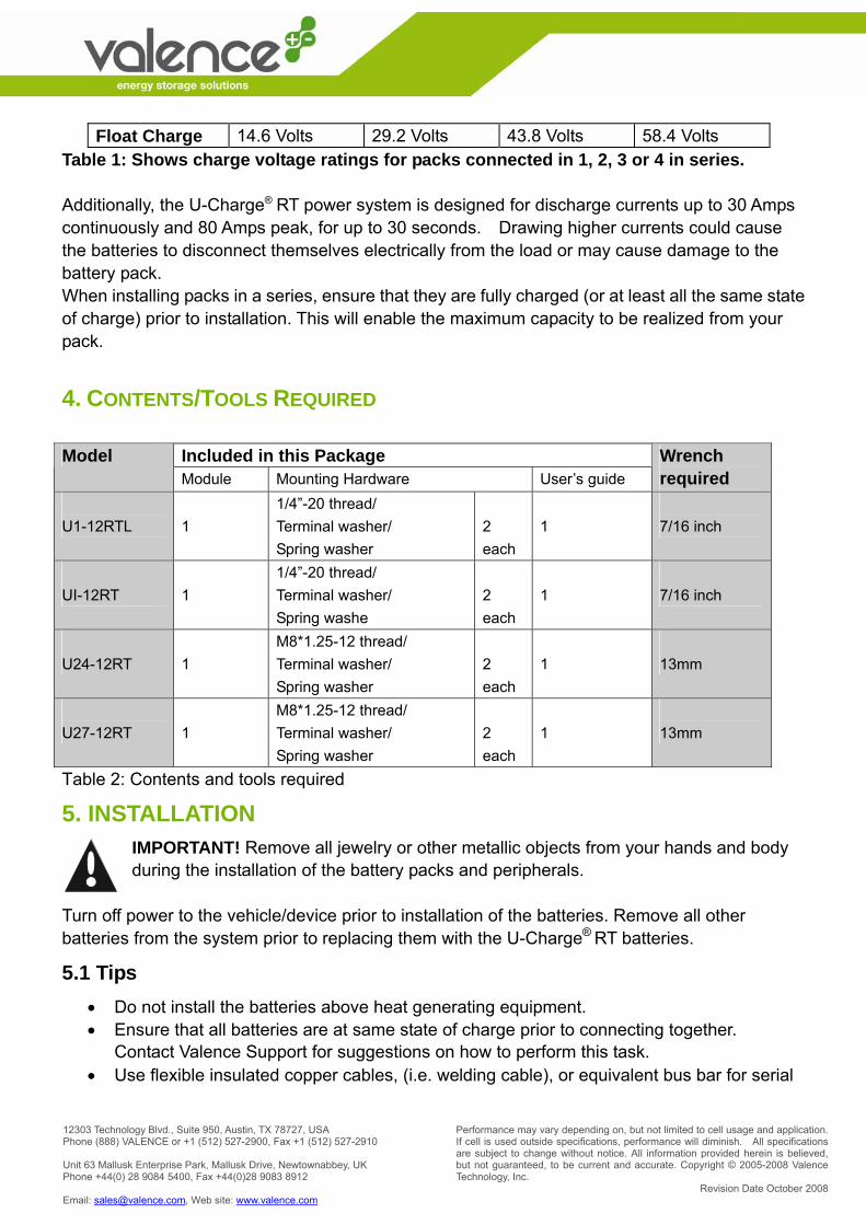
Float Charge 14.6 Volts 29.2 Volts 43.8 Volts 58.4 Volts Table 1: Shows charge voltage ratings for packs connected in 1, 2, 3 or 4 in series. Additionally, the U-Charge® RT power system is designed for discharge currents up to 30 Amps continuously and 80 Amps peak, for up to 30 seconds. Drawing higher currents could cause the batteries to disconnect themselves electrically from the load or may cause damage to the battery pack. When installing packs in a series, ensure that they are fully charged (or at least all the same state of charge) prior to installation. This will enable the maximum capacity to be realized from your pack.
4. CONTENTS/TOOLS REQUIRED
Included in this Package Model Module Mounting Hardware User’s guide
Wrench required
U1-12RTL
1
1/4”-20 thread/ Terminal washer/ Spring washer
2 each
1
7/16 inch
UI-12RT
1
1/4”-20 thread/ Terminal washer/ Spring washe
2 each
1
7/16 inch
U24-12RT
1
M8*1.25-12 thread/ Terminal washer/ Spring washer
2 each
1
13mm
U27-12RT
1
M8*1.25-12 thread/ Terminal washer/ Spring washer
2 each
1
13mm
Table 2: Contents and tools required
5. INSTALLATION IMPORTANT! Remove all jewelry or other metallic objects from your hands and body during the installation of the battery packs and peripherals.
Turn off power to the vehicle/device prior to installation of the batteries. Remove all other batteries from the system prior to replacing them with the U-Charge® RT batteries.
5.1 Tips • Do not install the batteries above heat generating equipment. • Ensure that all batteries are at same state of charge prior to connecting together.
Contact Valence Support for suggestions on how to perform this task. • Use flexible insulated copper cables, (i.e. welding cable), or equivalent bus bar for serial
Performance may vary depending on, but not limited to cell usage and application. If cell is used outside specifications, performance will diminish. All specifications are subject to change without notice. All information provided herein is believed, but not guaranteed, to be current and accurate. Copyright © 2005-2008 Valence Technology, Inc.
Revision Date October 2008
12303 Technology Blvd., Suite 950, Austin, TX 78727, USA Phone (888) VALENCE or +1 (512) 527-2900, Fax +1 (512) 527-2910 Unit 63 Mallusk Enterprise Park, Mallusk Drive, Newtownabbey, UK Phone +44(0) 28 9084 5400, Fax +44(0)28 9083 8912 Email: [email protected], Web site: www.valence.com
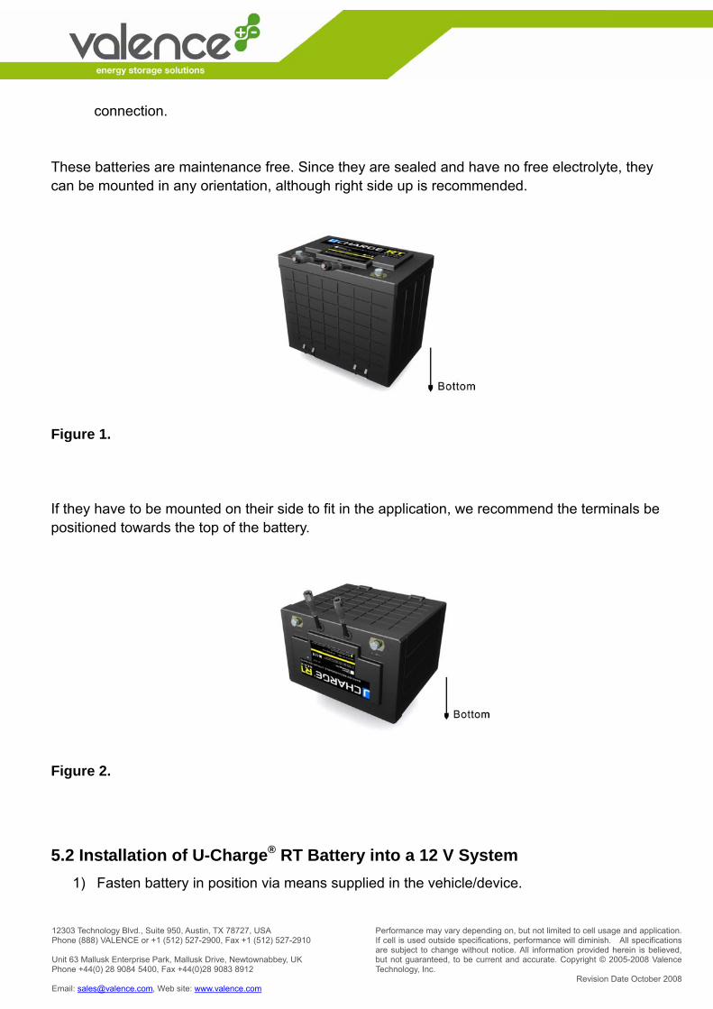
connection. These batteries are maintenance free. Since they are sealed and have no free electrolyte, they can be mounted in any orientation, although right side up is recommended.
Figure 1. If they have to be mounted on their side to fit in the application, we recommend the terminals be positioned towards the top of the battery.
Figure 2.
5.2 Installation of U-Charge® RT Battery into a 12 V System 1) Fasten battery in position via means supplied in the vehicle/device.
Performance may vary depending on, but not limited to cell usage and application. If cell is used outside specifications, performance will diminish. All specifications are subject to change without notice. All information provided herein is believed, but not guaranteed, to be current and accurate. Copyright © 2005-2008 Valence Technology, Inc.
Revision Date October 2008
12303 Technology Blvd., Suite 950, Austin, TX 78727, USA Phone (888) VALENCE or +1 (512) 527-2900, Fax +1 (512) 527-2910 Unit 63 Mallusk Enterprise Park, Mallusk Drive, Newtownabbey, UK Phone +44(0) 28 9084 5400, Fax +44(0)28 9083 8912 Email: [email protected], Web site: www.valence.com
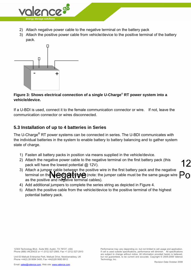
2) Attach negative power cable to the negative terminal on the battery pack 3) Attach the positive power cable from vehicle/device to the positive terminal of the battery
pack.
Figure 3: Shows electrical connection of a single U-Charge® RT power system into a vehicle/device. If a U-BDI is used, connect it to the female communication connector or wire. If not, leave the communication connector or wires disconnected.
5.3 Installation of up to 4 batteries in Series The U-Charge® RT power systems can be connected in series. The U-BDI communicates with the individual batteries in the system to enable battery to battery balancing and to gather system state of charge.
1) Fasten all battery packs in position via means supplied in the vehicle/device. 2) Attach the negative power cable to the negative terminal on the first battery pack (this
pack will have the lowest potential @ 12V). 3) Attach a jumper cable between the positive wire in the first battery pack and the negative
terminal on the second battery pack (note: the jumper cable must be the same gauge wire as the positive and negative terminal cables).
4) Add additional jumpers to complete the series string as depicted in Figure 4. 5) Attach the positive cable from the vehicle/device to the positive terminal of the highest
potential battery pack.
Performance may vary depending on, but not limited to cell usage and application. If cell is used outside specifications, performance will diminish. All specifications are subject to change without notice. All information provided herein is believed, but not guaranteed, to be current and accurate. Copyright © 2005-2008 Valence Technology, Inc.
Revision Date October 2008
12303 Technology Blvd., Suite 950, Austin, TX 78727, USA Phone (888) VALENCE or +1 (512) 527-2900, Fax +1 (512) 527-2910 Unit 63 Mallusk Enterprise Park, Mallusk Drive, Newtownabbey, UK Phone +44(0) 28 9084 5400, Fax +44(0)28 9083 8912 Email: [email protected], Web site: www.valence.com
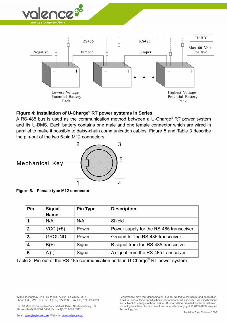
Figure 4: Installation of U-Charge® RT power systems in Series. A RS-485 bus is used as the communication method between a U-Charge® RT power system and its U-BMS. Each battery contains one male and one female connector which are wired in parallel to make it possible to daisy-chain communication cables. Figure 5 and Table 3 describe the pin-out of the two 5-pin M12 connectors:
Mechanica l Key
1
2
4
3
5
Figure 5. Female type M12 connector
Pin Signal Name
Pin Type Description
1 N/A N/A Shield
2 VCC (+5) Power Power supply for the RS-485 transceiver
3 GROUND Power Ground for the RS-485 transceiver
4 B(+) Signal B signal from the RS-485 transceiver
5 A (-) Signal A signal from the RS-485 transceiver
Table 3: Pin-out of the RS-485 communication ports in U-Charge® RT power system
Performance may vary depending on, but not limited to cell usage and application. If cell is used outside specifications, performance will diminish. All specifications are subject to change without notice. All information provided herein is believed, but not guaranteed, to be current and accurate. Copyright © 2005-2008 Valence Technology, Inc.
Revision Date October 2008
12303 Technology Blvd., Suite 950, Austin, TX 78727, USA Phone (888) VALENCE or +1 (512) 527-2900, Fax +1 (512) 527-2910 Unit 63 Mallusk Enterprise Park, Mallusk Drive, Newtownabbey, UK Phone +44(0) 28 9084 5400, Fax +44(0)28 9083 8912 Email: [email protected], Web site: www.valence.com
6. CHARGING THE BATTERIES
6.1 Select a Proper Battery Charger When choosing a charger, please use the following minimum guidelines for selection.
• The charger should deliver a DC current with as small a ripple current as possible. • The charger should have a reliable and accurate voltage regulator. • The current from the charger should be controlled in all situations.
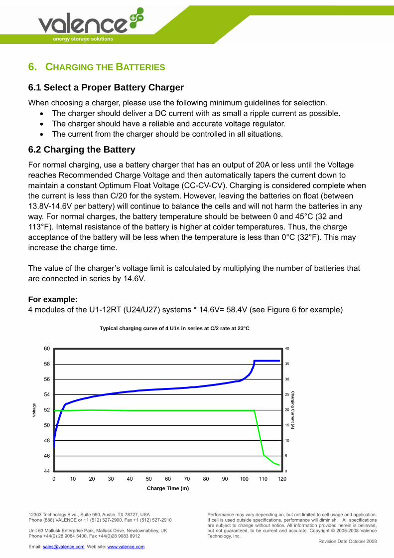
6.2 Charging the Battery For normal charging, use a battery charger that has an output of 20A or less until the Voltage reaches Recommended Charge Voltage and then automatically tapers the current down to maintain a constant Optimum Float Voltage (CC-CV-CV). Charging is considered complete when the current is less than C/20 for the system. However, leaving the batteries on float (between 13.8V-14.6V per battery) will continue to balance the cells and will not harm the batteries in any way. For normal charges, the battery temperature should be between 0 and 45°C (32 and 113°F). Internal resistance of the battery is higher at colder temperatures. Thus, the charge acceptance of the battery will be less when the temperature is less than 0°C (32°F). This may increase the charge time. The value of the charger’s voltage limit is calculated by multiplying the number of batteries that are connected in series by 14.6V. For example: 4 modules of the U1-12RT (U24/U27) systems * 14.6V= 58.4V (see Figure 6 for example)
Typical charging curve of 4 U1s in series at C/2 rate at 23°C
44
46
48
50
52
54
56
58
60
0 10 20 30 40 50 60 70 80 90 100 110 120
Charge Time (m)
Volta
ge
0
5
10
15
20
25
30
35
40
Charging C
urrent (A)
Performance may vary depending on, but not limited to cell usage and application. If cell is used outside specifications, performance will diminish. All specifications are subject to change without notice. All information provided herein is believed, but not guaranteed, to be current and accurate. Copyright © 2005-2008 Valence Technology, Inc.
Revision Date October 2008
12303 Technology Blvd., Suite 950, Austin, TX 78727, USA Phone (888) VALENCE or +1 (512) 527-2900, Fax +1 (512) 527-2910 Unit 63 Mallusk Enterprise Park, Mallusk Drive, Newtownabbey, UK Phone +44(0) 28 9084 5400, Fax +44(0)28 9083 8912 Email: [email protected], Web site: www.valence.com
Figure 6. Example for charging 4 U-Charge® batteries:
• Charge to 58.4V = (14.6V x 4 batteries in series) and hold. • When voltage reaches 58.4, the battery is approximately 90% charged. • Allow the current to naturally decay when voltage is reached. • When the current drops below 2A for U1, 5A for U24, and 6A for U27, the battery is
considered 100% charged. • Continue to float charge at 58.4V. • It will not hurt the battery if the voltage is continuously present, even after 100% SOC
is reached. This will aid in balancing. If you have any questions, please call Valence Technology for the recommended charging profile for your system. If a U-BDI is attached, the 10 bar LEDs will light up according to the system’s state of charge. Once any cell has reached 3.65V, the yellow LED will illuminate. This is normal and is just telling the user that balancing has started to occur.
7. U-CHARGE® RT POWER SYSTEM FEATURES The U-Charge® RT power system includes electronics that monitor conditions of the battery pack.
• Built-in electronic monitoring for state-of-charge, current, voltage and temperature • Built-in and automatic over voltage, over temperature and over discharge protection • Internal cell balancing • LED battery status indicator • Series connection up to 48V (nominal) maximum system voltage • Rugged mechanical design – dust and water resistant to IP56 standards, flame retardant
plastics • Handles on U24, and U27 models • Hundreds of cycles, under normal conditions • Maintenance-free • Can be recharged using most standard lead-acid chargers (set for AGM/GEL cells) *verify
with Valence Customer Support before charging • Communication of monitored data via optional RT Monitoring Kit (part number 1004236) • State of charge displayed via U-BDI (part number 1002867)
7.1 Discharge Control When the modules are discharged to the point where any single cell block reaches its minimum value, 2.45V, the battery will interrupt discharge. The battery will appear to have 0V (or even

Performance may vary depending on, but not limited to cell usage and application. If cell is used outside specifications, performance will diminish. All specifications are subject to change without notice. All information provided herein is believed, but not guaranteed, to be current and accurate. Copyright © 2005-2008 Valence Technology, Inc.
Revision Date October 2008
12303 Technology Blvd., Suite 950, Austin, TX 78727, USA Phone (888) VALENCE or +1 (512) 527-2900, Fax +1 (512) 527-2910 Unit 63 Mallusk Enterprise Park, Mallusk Drive, Newtownabbey, UK Phone +44(0) 28 9084 5400, Fax +44(0)28 9083 8912 Email: [email protected], Web site: www.valence.com
negative voltage) across the terminals. No current will flow. However, the battery will accept charge. When the battery has a GREEN LED status indication, it can be discharged in a normal manner. If the LED is YELLOW, the battery is either nearing a thermal limit or the capacity is less than 20% SOC. If any battery has a RED LED status indication, it will stop discharging. A battery will also stop discharging once it has exhausted capacity. In this case, it will return to normal (GREEN LED) once the cell voltage increases over 2.7V during charge.
7.2 Charge Control When the modules are charged to the point where any single cell block reaches its maximum value, 3.9V, the battery will prohibit further charging by opening up an internal disconnect. When the voltage of the cell returns to a value less than 3.7V, its internal disconnects will automatically reset.
7.3 State Of Charge (SOC) Measurement Individual cell voltage and charge/discharge current will be used to measure the state-of-charge (SOC) of the battery. The estimated capacity used for the calculations will be adjusted to meet the capacity of the lowest capacity cell bank when the pack is fully cycled. The state-of-charge will be adjusted for normal self-discharge of the battery when the unit is not on charge. SOC Accuracy is greater than 90%.
NOTE: Lead acid state-of-charge meters should not be used with U-Charge® power systems from Valence Technology. They will not be accurate.
7.4 Cell Balancing Battery cell variability and environmental conditions can cause slight state-of-charge imbalances between cells. This imbalance can cause reduced capacity of traditional battery systems. To minimize potential capacity issues, the battery automatically performs adjustments to balance the state-of charge in the cells during the top of charge.
Performance may vary depending on, but not limited to cell usage and application. If cell is used outside specifications, performance will diminish. All specifications are subject to change without notice. All information provided herein is believed, but not guaranteed, to be current and accurate. Copyright © 2005-2008 Valence Technology, Inc.
Revision Date October 2008
12303 Technology Blvd., Suite 950, Austin, TX 78727, USA Phone (888) VALENCE or +1 (512) 527-2900, Fax +1 (512) 527-2910 Unit 63 Mallusk Enterprise Park, Mallusk Drive, Newtownabbey, UK Phone +44(0) 28 9084 5400, Fax +44(0)28 9083 8912 Email: [email protected], Web site: www.valence.com
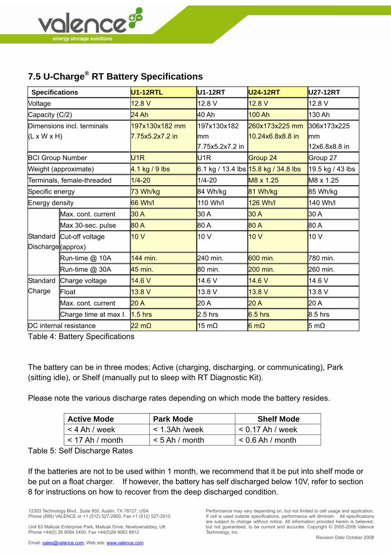
7.5 U-Charge® RT Battery Specifications Specifications U1-12RTL U1-12RT U24-12RT U27-12RT Voltage 12.8 V 12.8 V 12.8 V 12.8 V Capacity (C/2) 24 Ah 40 Ah 100 Ah 130 Ah Dimensions incl. terminals (L x W x H)
197x130x182 mm 7.75x5.2x7.2 in
197x130x182 mm 7.75x5.2x7.2 in
260x173x225 mm 10.24x6.8x8.8 in
306x173x225 mm 12x6.8x8.8 in
BCI Group Number U1R U1R Group 24 Group 27 Weight (approximate) 4.1 kg / 9 lbs 6.1 kg / 13.4 lbs 15.8 kg / 34.8 lbs 19.5 kg / 43 lbs Terminals, female-threaded 1/4-20 1/4-20 M8 x 1.25 M8 x 1.25 Specific energy 73 Wh/kg 84 Wh/kg 81 Wh/kg 85 Wh/kg Energy density 66 Wh/l 110 Wh/l 126 Wh/l 140 Wh/l
Max. cont. current 30 A 30 A 30 A 30 A Max 30-sec. pulse 80 A 80 A 80 A 80 A Cut-off voltage (approx)
10 V 10 V 10 V 10 V
Run-time @ 10A 144 min. 240 min. 600 min. 780 min.
Standard Discharge
Run-time @ 30A 45 min. 80 min. 200 min. 260 min. Charge voltage 14.6 V 14.6 V 14.6 V 14.6 V Float 13.8 V 13.8 V 13.8 V 13.8 V Max. cont. current 20 A 20 A 20 A 20 A
Standard Charge
Charge time at max I. 1.5 hrs 2.5 hrs 6.5 hrs 8.5 hrs DC internal resistance 22 mΩ 15 mΩ 6 mΩ 5 mΩ Table 4: Battery Specifications The battery can be in three modes; Active (charging, discharging, or communicating), Park (sitting idle), or Shelf (manually put to sleep with RT Diagnostic Kit). Please note the various discharge rates depending on which mode the battery resides.
Active Mode Park Mode Shelf Mode < 4 Ah / week < 1.3Ah /week < 0.17 Ah / week < 17 Ah / month < 5 Ah / month < 0.6 Ah / month
Table 5: Self Discharge Rates If the batteries are not to be used within 1 month, we recommend that it be put into shelf mode or be put on a float charger. If however, the battery has self discharged below 10V, refer to section 8 for instructions on how to recover from the deep discharged condition.
Performance may vary depending on, but not limited to cell usage and application. If cell is used outside specifications, performance will diminish. All specifications are subject to change without notice. All information provided herein is believed, but not guaranteed, to be current and accurate. Copyright © 2005-2008 Valence Technology, Inc.
Revision Date October 2008
12303 Technology Blvd., Suite 950, Austin, TX 78727, USA Phone (888) VALENCE or +1 (512) 527-2900, Fax +1 (512) 527-2910 Unit 63 Mallusk Enterprise Park, Mallusk Drive, Newtownabbey, UK Phone +44(0) 28 9084 5400, Fax +44(0)28 9083 8912 Email: [email protected], Web site: www.valence.com
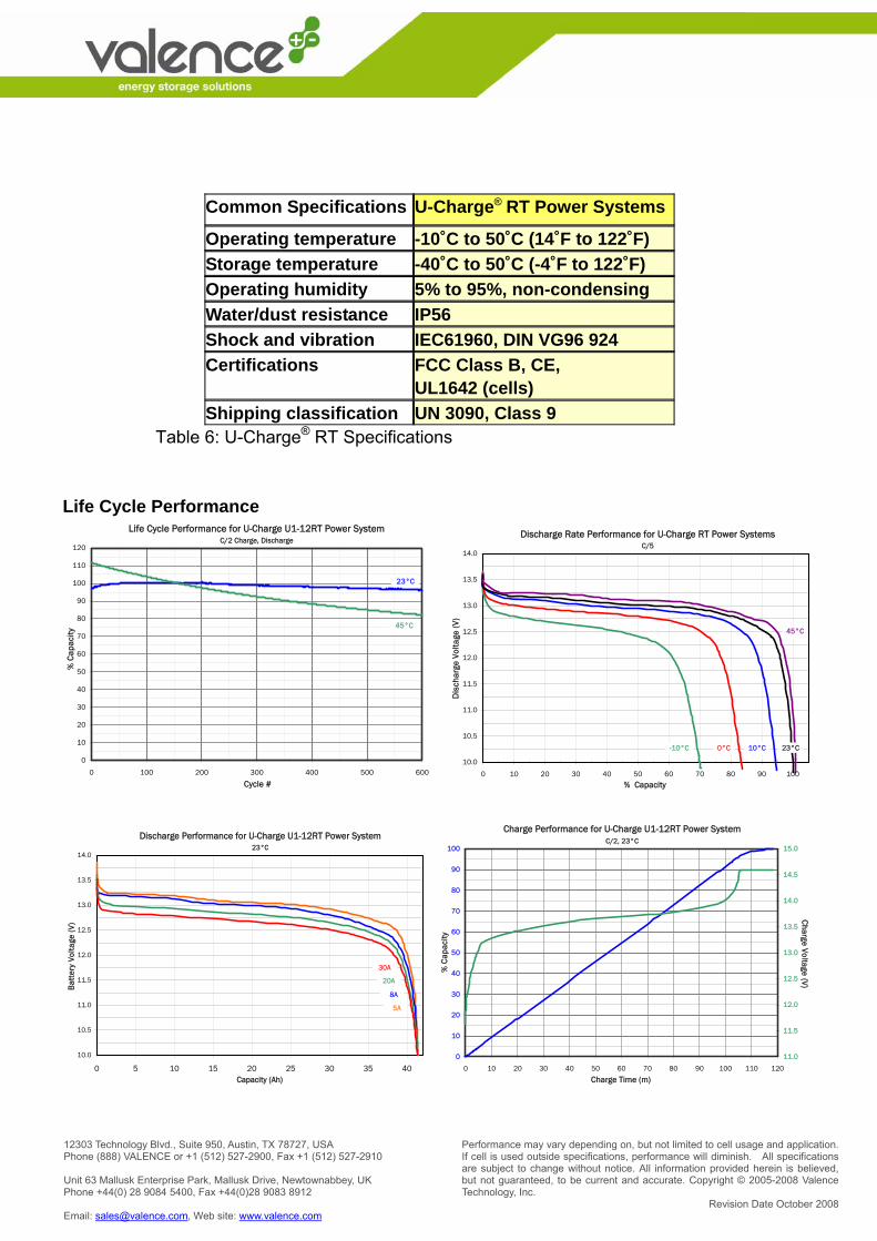
Common Specifications U-Charge® RT Power Systems
Operating temperature -10˚C to 50˚C (14˚F to 122˚F) Storage temperature -40˚C to 50˚C (-4˚F to 122˚F) Operating humidity 5% to 95%, non-condensing Water/dust resistance IP56 Shock and vibration IEC61960, DIN VG96 924 Certifications FCC Class B, CE,
UL1642 (cells) Shipping classification UN 3090, Class 9
Table 6: U-Charge® RT Specifications Life Cycle Performance
Charge Performance for U-Charge U1-12RT Power SystemC/2, 23°C
0
10
20
30
40
50
60
70
80
90
100
0 10 20 30 40 50 60 70 80 90 100 110 120
Charge Time (m)
% C
apac
ity
11.0
11.5
12.0
12.5
13.0
13.5
14.0
14.5
15.0
Charge Voltage (V)
Discharge Performance for U-Charge U1-12RT Power System23°C
10.0
10.5
11.0
11.5
12.0
12.5
13.0
13.5
14.0
0 5 10 15 20 25 30 35 40 Capacity (Ah)
Bat
tery
Vol
tage
(V)
8A
30A
20A
5A5A
8A
Discharge Rate Performance for U-Charge RT Power SystemsC/5
10.0
10.5
11.0
11.5
12.0
12.5
13.0
13.5
14.0
0 10 20 30 40 50 60 70 80 90 100
% Capacity
Dis
char
ge V
olta
ge (V
)
45°C
23°C10°C0°C-10°C
Life Cycle Performance for U-Charge U1-12RT Power SystemC/2 Charge, Discharge
0
10
20
30
40
50
60
70
80
90
100
110
120
0 100 200 300 400 500 600
Cycle #
% C
apac
ity
23°C
45°C
Performance may vary depending on, but not limited to cell usage and application. If cell is used outside specifications, performance will diminish. All specifications are subject to change without notice. All information provided herein is believed, but not guaranteed, to be current and accurate. Copyright © 2005-2008 Valence Technology, Inc.
Revision Date October 2008
12303 Technology Blvd., Suite 950, Austin, TX 78727, USA Phone (888) VALENCE or +1 (512) 527-2900, Fax +1 (512) 527-2910 Unit 63 Mallusk Enterprise Park, Mallusk Drive, Newtownabbey, UK Phone +44(0) 28 9084 5400, Fax +44(0)28 9083 8912 Email: [email protected], Web site: www.valence.com
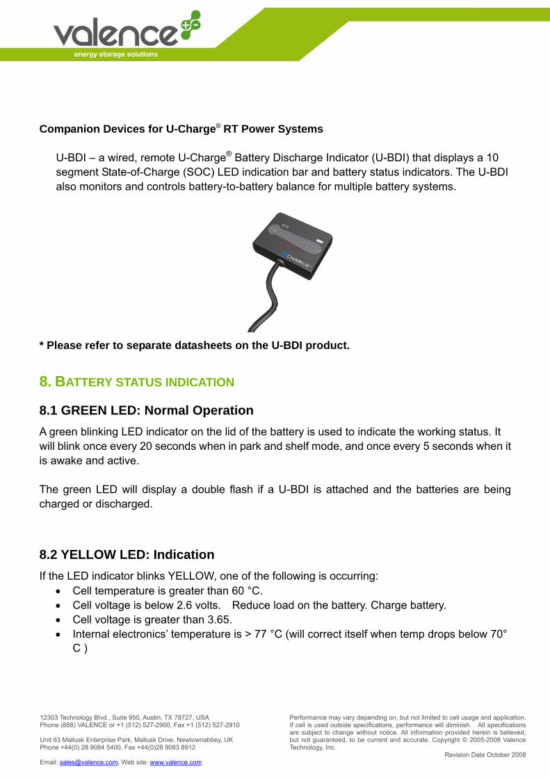
Companion Devices for U-Charge® RT Power Systems
U-BDI – a wired, remote U-Charge® Battery Discharge Indicator (U-BDI) that displays a 10 segment State-of-Charge (SOC) LED indication bar and battery status indicators. The U-BDI also monitors and controls battery-to-battery balance for multiple battery systems.
* Please refer to separate datasheets on the U-BDI product.
8. BATTERY STATUS INDICATION
8.1 GREEN LED: Normal Operation
A green blinking LED indicator on the lid of the battery is used to indicate the working status. It will blink once every 20 seconds when in park and shelf mode, and once every 5 seconds when it is awake and active. The green LED will display a double flash if a U-BDI is attached and the batteries are being charged or discharged.
8.2 YELLOW LED: Indication If the LED indicator blinks YELLOW, one of the following is occurring:
• Cell temperature is greater than 60 °C. • Cell voltage is below 2.6 volts. Reduce load on the battery. Charge battery. • Cell voltage is greater than 3.65. • Internal electronics’ temperature is > 77 °C (will correct itself when temp drops below 70°
C )
Performance may vary depending on, but not limited to cell usage and application. If cell is used outside specifications, performance will diminish. All specifications are subject to change without notice. All information provided herein is believed, but not guaranteed, to be current and accurate. Copyright © 2005-2008 Valence Technology, Inc.
Revision Date October 2008
12303 Technology Blvd., Suite 950, Austin, TX 78727, USA Phone (888) VALENCE or +1 (512) 527-2900, Fax +1 (512) 527-2910 Unit 63 Mallusk Enterprise Park, Mallusk Drive, Newtownabbey, UK Phone +44(0) 28 9084 5400, Fax +44(0)28 9083 8912 Email: [email protected], Web site: www.valence.com
8.3 RED LED: Fault Indication If the LED indicator blinks RED, one of the following has occurred:
• Cell voltage is < 2.45V even after 1 minute of charging. • Internal electronics’ temperature is between 85 and 100 °C. • If it’s red due to an over discharge or self discharge condition and the LED is blinking
slowly (on for 2 seconds, off for 3 seconds), see NOTICE below section 8.4.
8.4 No LED Indication: Severely Over Discharged
If the LED indictor is not blinking and the battery voltage is below 7V: • Charge with 1A until the lowest cell voltage reaches 2.7V and the LED blinks green. At
this point, use a normal charger (<20A) to charge the battery normally. (see NOTICE below)
• The individual cell voltages can be viewed with the RT Monitoring and Diagnostic Kit (Valence part number 1004236).
NOTICE: If the battery was charged at a higher current than 1A and the lowest cell bank do not reach 2.45V within one minute, the battery will lock up and flash the slow red flashing state (Red LED on for 2 sec. then off for 3 sec.). Once in this state the battery must be allowed to sit open circuit for approx. 12 hours or longer depending on battery type (U1 to U27) and the battery voltage. The overall battery voltage must fall below 5.35V. This is the point when the LED will change from slow flashing red to fast flashing yellow or no LED at all, before it can be charged with 1A again. Contact Valence Technology, Inc. or the dealer where the U-Charge® RT power system was purchased for further information.
9. TIPS FOR OPTIMIZING PERFORMANCE By following the tips listed below, you can assure long life and high performance of your U-Charge® RT power system:
• Charge all batteries fully prior to first use of the vehicle/device. • Allow battery to charge fully over night periodically. • Use at temperatures below 40ºC. • Charge battery fully and put into Shelf Mode prior to long storage periods. • Recharge battery fully if it has been stored for more than three (3) months. • Ensure that all batteries are secured into position to minimize damage from shock and
vibration. • Periodically inspect electrical connections to ensure screws are tight and no corrosion is
Performance may vary depending on, but not limited to cell usage and application. If cell is used outside specifications, performance will diminish. All specifications are subject to change without notice. All information provided herein is believed, but not guaranteed, to be current and accurate. Copyright © 2005-2008 Valence Technology, Inc.
Revision Date October 2008
12303 Technology Blvd., Suite 950, Austin, TX 78727, USA Phone (888) VALENCE or +1 (512) 527-2900, Fax +1 (512) 527-2910 Unit 63 Mallusk Enterprise Park, Mallusk Drive, Newtownabbey, UK Phone +44(0) 28 9084 5400, Fax +44(0)28 9083 8912 Email: [email protected], Web site: www.valence.com
present. • Use recommended torque ratings for the bolts.
o U1- Torque provided hardware to 110 in-lbs maximum (12.4 Nm). Retorque on occasion to 85 in-lbs (9.6 Nm)
o U24, and U27- Torque provided hardware to 160 in-lbs maximum (18 Nm). Retorque on occasion to125 in-lbs (14.1 Nm).
• Proper thermal management will maximize life. This includes adequate air cooling.
10. MAINTENANCE AND STORAGE
10.1 Visual Inspection Please perform regular visual inspections of the battery chassis. If the battery chassis is found to have dents, discoloration, or appears to be damaged in any way, DISCONTINUE USE IMMEDIATELY. Please contact Valence Technology for assistance with evaluating the product for continued usability.
10.2 Voltage Checking The voltage of the battery can be monitored during normal operation or as part of standard tests performed periodically to assess the health of the battery.
• If any single battery's voltage is under 10V at room temperature, the battery has been over-discharged or is self-discharging due to some defect or parasitic load. Discontinue use until the fault can be corrected and the battery can be recharged.
10.3 Battery Storage When disconnected from other batteries and the U-BDI, the battery will automatically go into a park mode. In this state, the battery needs to be recharged at the following interval: U1-12RTL U1-12RT U24-12RT U27-12RT Recharge after 2 months 4 months 6 months 6 months Table 7: Recharge Guidelines
• However, if any battery is not going to be used within 6 months, we recommend that the battery be put into shelf mode using the RT Diagnostic Kit. The shelf function instructs the monitoring circuitry to shut down to maximize shelf life. In shelf mode, a 100% charged battery could be stored safely for up to a year without the need for recharge, although monthly voltage tests are recommended.
Performance may vary depending on, but not limited to cell usage and application. If cell is used outside specifications, performance will diminish. All specifications are subject to change without notice. All information provided herein is believed, but not guaranteed, to be current and accurate. Copyright © 2005-2008 Valence Technology, Inc.
Revision Date October 2008
12303 Technology Blvd., Suite 950, Austin, TX 78727, USA Phone (888) VALENCE or +1 (512) 527-2900, Fax +1 (512) 527-2910 Unit 63 Mallusk Enterprise Park, Mallusk Drive, Newtownabbey, UK Phone +44(0) 28 9084 5400, Fax +44(0)28 9083 8912 Email: [email protected], Web site: www.valence.com
• If the batteries are to be stored for longer than a year, please connect the batteries to a charger and perform a maintenance charge. The module must be told to exit shelf mode before charging can occur.
• Test the open circuit voltage periodically and recharge if it is at or below 12V. Monthly tests are recommended.
• Store in an open, well ventilated, dry, clean area, between -40°C and 45°C (-40°F and 113°F) for maximum life. Self discharge is accelerated at higher temperatures.
• Do not expose the battery to extremes of temperature over 60°C (140°F). • Do not expose the battery directly to sources of heat. • Do not expose the battery to direct sunlight or moisture and/or precipitation • Handle each battery carefully to avoid sharp impacts or extreme pressure on the case.
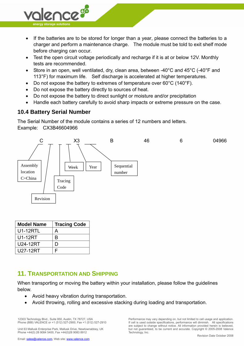
10.4 Battery Serial Number The Serial Number of the module contains a series of 12 numbers and letters. Example: CX3B46604966 C X3 B 46 6 04966
Model Name Tracing Code U1-12RTL A U1-12RT B U24-12RT D U27-12RT F
11. TRANSPORTATION AND SHIPPING When transporting or moving the battery within your installation, please follow the guidelines below.
• Avoid heavy vibration during transportation. • Avoid throwing, rolling and excessive stacking during loading and transportation.
Assembly location C=China
Revision
Tracing Code
Week Year Sequential number
Performance may vary depending on, but not limited to cell usage and application. If cell is used outside specifications, performance will diminish. All specifications are subject to change without notice. All information provided herein is believed, but not guaranteed, to be current and accurate. Copyright © 2005-2008 Valence Technology, Inc.
Revision Date October 2008
12303 Technology Blvd., Suite 950, Austin, TX 78727, USA Phone (888) VALENCE or +1 (512) 527-2900, Fax +1 (512) 527-2910 Unit 63 Mallusk Enterprise Park, Mallusk Drive, Newtownabbey, UK Phone +44(0) 28 9084 5400, Fax +44(0)28 9083 8912 Email: [email protected], Web site: www.valence.com
• Make sure that all cables and external connectors are disconnected and removed from the battery prior to moving it.
If the product needs to be shipped to a different location or sent back to Valence Technology, Inc. for any reason, please follow the guidelines below carefully.
1. Disconnect all cables, both power and communications from the batteries. 2. Pack the batteries in “dangerous goods” certified boxes and packaging materials as
specified by the Department of Transportation (DOT). The packaging must protect the contents from reasonable handling damage and prevent short circuits from taking place.
3. The package should be prepared for shipment and shipping documents should be signed by an individual who is certified to handle and prepare products that have been designated as “Dangerous Goods” for shipment.
4. Ship under regulations UN3090, Class 9 - “Dangerous Goods”.
NOTE: The U-Charge® RT power system is shipped in a specially designed box to provide maximum protection for the contents. We strongly recommend that you save this box and use it whenever you need to transport or ship the battery. Please follow all local laws/regulations regarding the shipment of lithium-ion
batteries.
12. BATTERY OVERHEATING If the charger malfunctions or the system continues to overcharge the battery past 100% for a given amount of time AND the safety disconnect device fails, the battery can be damaged beyond repair, and in some cases get extremely hot possibly releasing smoke and melting plastics. If a battery begins to smoke or melt;
• remove charging source immediately. • move the battery to a well ventilated area, if possible - preferably outside. • use a Carbon Dioxide, Dry Chemical or appropriate foam fire extinguisher to spray the
hot battery. Note :If a fire extinguisher is not available, use copious amounts of water, or cover the battery with sand.
12.1 Emergency and First Aid Procedures In the event of exposure to battery contents the following could occur:
• Vapor or mist is irritating to the eyes, mucous membranes and respiratory tract. • Causes eye and skin irritation. • Exposure can cause nausea, dizziness and headache.
In case of contact with the battery’s electrolyte:
• Immediately flush eyes with copious amounts of water for at least 15 minutes.
Performance may vary depending on, but not limited to cell usage and application. If cell is used outside specifications, performance will diminish. All specifications are subject to change without notice. All information provided herein is believed, but not guaranteed, to be current and accurate. Copyright © 2005-2008 Valence Technology, Inc.
Revision Date October 2008
12303 Technology Blvd., Suite 950, Austin, TX 78727, USA Phone (888) VALENCE or +1 (512) 527-2900, Fax +1 (512) 527-2910 Unit 63 Mallusk Enterprise Park, Mallusk Drive, Newtownabbey, UK Phone +44(0) 28 9084 5400, Fax +44(0)28 9083 8912 Email: [email protected], Web site: www.valence.com
• Assure adequate flushing of the eyes by separating the eyelids with fingers. • Flush skin with water. • Remove and wash contaminated clothing promptly.
If inhaled:
• Remove oneself to fresh air. If not breathing or difficulty breathing:
• Give artificial respiration. • If breathing is difficult, give oxygen.
If swallowed:
• Wash out mouth with water provided person is conscious.
In all cases, CALL A PHYSICIAN!
13. DISPOSAL OF BATTERIES Customers should select an appropriate and responsible disposal method that satisfies state and local requirements when disposing of lithium-ion batteries. Commonly available methods include disposal and collection by a licensed waste company or recycling. Some states and communities have programs for collecting and/or recycling spent batteries. Valence Technology, Inc. cannot predict if current lithium-ion battery disposal requirements will change in the future that would require specially mandated handling and disposal techniques. If you have any questions regarding state or local disposal requirements, please contact your local environmental authority. Batteries have residual electrical charge. Please be sure to completely discharge batteries before disposing them. For ideas on simple methods of discharging batteries, please contact Valence Technologies. If you are not sure if your waste facility can handle lithium-ion batteries, contact them and verify if they are permitted or not.
13.1 Recycling
The Rechargeable Battery Recycling Corporation's web site, www.rbrc.org, is an excellent source for finding a facility to handle these types of batteries. To encourage recycling of spent batteries, the Environmental Protection Agency (EPA) allows spent batteries that are shipped to a recycling facility, to be shipped as “universal wastes” instead of “dangerous goods.” The shipping requirements for “universal wastes” are available at the

Performance may vary depending on, but not limited to cell usage and application. If cell is used outside specifications, performance will diminish. All specifications are subject to change without notice. All information provided herein is believed, but not guaranteed, to be current and accurate. Copyright © 2005-2008 Valence Technology, Inc.
Revision Date October 2008
12303 Technology Blvd., Suite 950, Austin, TX 78727, USA Phone (888) VALENCE or +1 (512) 527-2900, Fax +1 (512) 527-2910 Unit 63 Mallusk Enterprise Park, Mallusk Drive, Newtownabbey, UK Phone +44(0) 28 9084 5400, Fax +44(0)28 9083 8912 Email: [email protected], Web site: www.valence.com
EPA website at www.epa.gov.
14. USE IN LIFE SUPPORT APPLICATIONS The U-Charge® RT power system SHALL NOT be used in, or in conjunction with, any Life Support Application without the express written consent of Valence Technology, Inc. Life Support Applications include, without limitation: (i) a device to be implanted in a human body; or (ii) a system or device, which supports or monitors a human life, such that its failure could cause serious injury or death.
15. LIMITED WARRANTY U-Charge® RT Power System Limited Warranty Valence Technology, Inc. (“Valence”) warrants the U-Charge® RT power system and its components (“Product”) as free from defects in materials or workmanship under normal use for a period (“Warranty Period”) of two (2) year from the date of original retail purchase. This warranty applies to the original purchaser (the “Customer”) only and is non-transferable. During the Warranty Period, should the Product, in Valence's opinion, malfunction, Valence's sole liability shall be, at Valence's sole discretion and at no charge to the customer, to either repair or replace the malfunctioning products if returned within the Warranty Period, freight prepaid, to the place of purchase or call 888-Valence (within the USA) or (001) 512-527-2900 (outside USA) for return instructions. Each returned Product must include a written statement detailing the nature of the claimed defect, as well as the Customer's name, address, phone number and a copy of the original sales receipt showing the date of purchase. Warranty is void if Valence determines the Product has been:
1. Serviced by anyone other than Valence; 2. Modified by improper installation of third-party products; 3. Damaged from accident, misuse, misapplication or abuse; 4. Damaged by improper transportation or packing when returned by the Customer to
Valence; 5. Damage by unusual physical stress or interference, failure or fluctuation of electrical
power, lightning, static electricity, fire, or other acts of God; or 6. Operated outside of the parameters of the Manual.
THIS WARRANTY IS MADE IN LIEU OF ALL OTHER WARRANTIES, WHETHER EXPRESSED OR IMPLIED, INCLUDING BUT NOT LIMITED TO, ANY IMPLIED WARRANTY OF MERCHANTABILITY OR FITNESS FOR A SPECIFIC PURPOSE. THE REMEDY SET FORTH HEREIN SHALL BE SOLE, EXCLUSIVE REMEDY WITH RESPECT TO THE
Performance may vary depending on, but not limited to cell usage and application. If cell is used outside specifications, performance will diminish. All specifications are subject to change without notice. All information provided herein is believed, but not guaranteed, to be current and accurate. Copyright © 2005-2008 Valence Technology, Inc.
Revision Date October 2008
12303 Technology Blvd., Suite 950, Austin, TX 78727, USA Phone (888) VALENCE or +1 (512) 527-2900, Fax +1 (512) 527-2910 Unit 63 Mallusk Enterprise Park, Mallusk Drive, Newtownabbey, UK Phone +44(0) 28 9084 5400, Fax +44(0)28 9083 8912 Email: [email protected], Web site: www.valence.com
PRODUCT. No person is authorized to make any other warranty or representation concerning the performance of the Product. Some jurisdictions do not allow exclusion of implied warranties, so the above exclusions may not apply to you. Any limited warranties that cannot be disclaimed are hereby limited to a term of one (1) year from the date of original retail purchase or, in the event relevant state law requires an implied warranty term exceeding one (1) year, for the briefest term allowable under relevant state law. Some states do not allow limitation on how long an implied warranty lasts, so the above limitation may not apply to you. Under no circumstances will Valence be liable for any indirect, special, incidental, or consequential damages, including any loss of revenue, loss of profit, or loss of data whether based on warranty, contract, tort, or any other legal theory, even if Valence has been advised of the possibility of such damages. Valence shall not be liable for any claims made by any third party or made by the Customer directly or indirectly on behalf of any third party. Some jurisdictions do not allow the exclusion or limitation of incidental or consequential damages, so the above limitation or seclusion may not apply to you. Valence reserves the right to change Product specifications or to discontinue the Product or other Valence products without prior notice. This warranty supersedes all previous Valence product warranties.