u n i s t r u t h a w a i i
TRANSCRIPT

U N I S T R U T
H A W A I I

P1000 • Twelve Gauge Channel, Solid
Area of Section 0.555 in2 (3.6 cm2)
Axis 1-1 Axis 2-2
Moment of Inertia (I) 0.185 in4 (7.7 cm4) 0.236 in4 (9.8 cm4)
Section Modulus (S) 0.202 in3 (3.3 cm3) 0.290 in3 (4.8 cm3)
Radius of Gyration (r)0.577 in (1.5 cm ) 0.651 in (1.7 cm )
Note:
• Above loads include the weight of the member. This weight must be deducted to arrive at the net allowable load the beam will support.• Long span beams should be supported so as to prevent rotation and twist.• Allowable uniformly distributed loads are listed for various simple spans, that is, a beam on two supports. If load is concentrated at the center of the span, multiply load from the table by 0.5 and corresponding deflection by 0.8.• The lateral bracing factor should be multiplied by the load to determine the load retained based on the distance between lateral braces.
P1000
U N I S T R U T H A W A I I
gen supportp3300p1001p1000Tp3300tp1001t
Tel 808-833-2502
General Support

P1075 • Bracket
Standard Dimensions:
• Hole Diameter: 9/16” (14mm)
• Hole Spacing (from end): 13/16” (21mm)
• Hole Spacing (on center): 1-7/8” (48mm)
• Width: 1-5/8” (41mm)
• Thickness: 1/4” (6mm)
Note:
• When used for mechanical supports, load capacities of brackts and
fittings should be in compliance with the American Standard Code for
Pressure Piping.
P1075
U N I S T R U T H A W A I I
Air Conditioning Equipment Support
Tel 808-833-2502

P1777 • Bracket
Standard Dimensions:
• Hole Diameter: 9/16” (14mm)
• Hole Spacing (From End): 13/16” (21mm)
• Hole Spacing (On Center): 1-7/8” (48mm)
• Width: 1-5/8” (41mm)
• Thickness: 1/4” (6mm)
Note:
• When used for mechanical supports, load capacities of brackets and
fittings should be in compliance with the American Standard Code for
Pressure Piping.
P1777
U N I S T R U T H A W A I I
Air Conditioning Equipment Support
Tel 808-833-2502
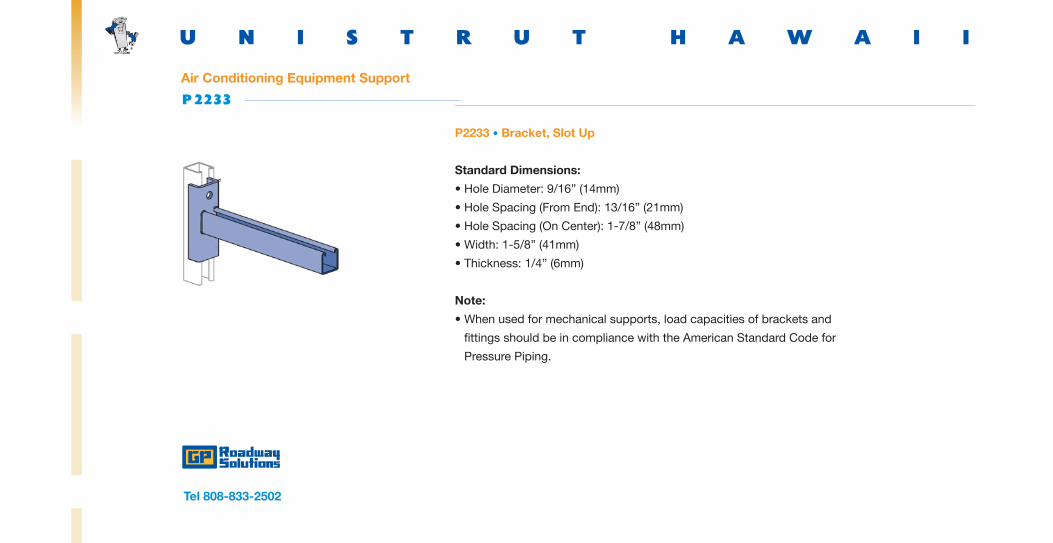
P2233 • Bracket, Slot Up
Standard Dimensions:
• Hole Diameter: 9/16” (14mm)
• Hole Spacing (From End): 13/16” (21mm)
• Hole Spacing (On Center): 1-7/8” (48mm)
• Width: 1-5/8” (41mm)
• Thickness: 1/4” (6mm)
Note:
• When used for mechanical supports, load capacities of brackets and
fittings should be in compliance with the American Standard Code for
Pressure Piping.
P2233
U N I S T R U T H A W A I I
Air Conditioning Equipment Support
Tel 808-833-2502

P2452 • Brace
Standard Dimensions:
• Hole Diameter: 9/16” (14mm)
• Hole Spacing (From End): 13/16” (21mm)
• Hole Spacing (On Center): 1-7/8” (48mm)
• Width: 1-5/8” (41mm)
• Thickness: 1/4” (6mm)
Note:
• When used for mechanical supports, load capacities of brackets and
fittings should be in compliance with the American Standard Code for
Pressure Piping.
P2452
U N I S T R U T H A W A I I
Air Conditioning Equipment Support
Tel 808-833-2502

P2458 • 18 Tubular Knee Braces
Standard Dimensions:
• Hole Diameter: 9/16” (14mm)
• Hole Spacing (From End): 13/16” (21mm)
• Hole Spacing (On Center): 1-7/8” (48mm)
• Width: 1-5/8” (41mm)
• Thickness: 1/4” (6mm)
Note:
• When used for mechanical supports, load capacities of brackets and
fittings should be in compliance with the American Standard Code for
Pressure Piping.
P2458-18
U N I S T R U T H A W A I I
Air Conditioning Equipment Support
Tel 808-833-2502

P1546, P2094 though P2100 • Two Hole, Outside Angle Fitting (1-5/8” series)
Standard Dimensions:
• Hole Diameter: 9/16” (14mm)
• Hole Spacing (from end): 13/16” (21mm)
• Hole Spacing (on center): 1-7/8” (48mm)
• Width: 1-5/8” (41mm)
• Thickness: 1/4” (6mm)
P1546
U N I S T R U T H A W A I I
Seismic Bracing
Tel 808-833-2502

P1354 • Four Hole Hinge
Standard Dimensions:
• Hole Diameter: 9/16” (14mm)
• Hole Spacing (from end): 13/16” (21mm)
• Hole Spacing (on center): 1-7/8” (48mm)
• Width: 1-5/8” (41mm)
• Thickness: 1/4” (6mm)
Note:
• When used for mechanical supports, load capacities of brackets and
fittings should be in compliance with the American Standard Code for
Pressure Piping.
P1354
U N I S T R U T H A W A I I
Seismic Bracing
Tel 808-833-2502
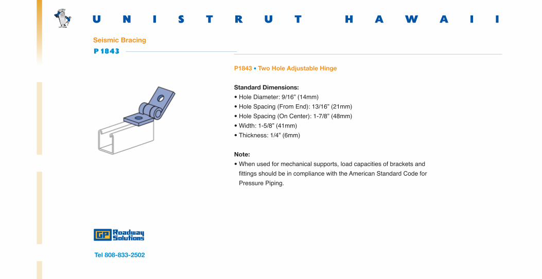
P1843 • Two Hole Adjustable Hinge
Standard Dimensions:
• Hole Diameter: 9/16” (14mm)• Hole Spacing (From End): 13/16” (21mm)• Hole Spacing (On Center): 1-7/8” (48mm)• Width: 1-5/8” (41mm)• Thickness: 1/4” (6mm)
Note:
• When used for mechanical supports, load capacities of brackets and fittings should be in compliance with the American Standard Code for Pressure Piping.
P1843
U N I S T R U T H A W A I I
Seismic Bracing
Tel 808-833-2502

P2485 • Cradle Clip
Materials:
• Unistrut channel nuts are manufactured from mild steel bars, and after
machining operations are completed, they are case hardened, assuring
positive biting action into the inturned edge of the Unistrut channel.
Threads:
• All threads on the nuts and bolts are Unified and American coarse screw
threads.
P2485
U N I S T R U T H A W A I I
Seismic Bracing
Tel 808-833-2502

SPF100 • Seismic Pivot Fitting
Standard Dimensions:
• Hole Diameter: 9/16” (14mm)
• Hole Spacing (From End): 13/16” (21mm)
• Hole Spacing (On Center): 1-7/8” (48mm)
• Width: 1-5/8” (41mm)
• Thickness: 1/4” (6mm)
Note:
• When used for mechanical supports, load capacities of brackets and
fittings should be in compliance with the American Standard Code for
Pressure Piping.
SPF100
U N I S T R U T H A W A I I
Seismic Bracing
Tel 808-833-2502

SPF200 • Adjustable Seismic Pivot Fitting
Standard Dimensions:
• Hole Diameter: 9/16” (14mm)
• Hole Spacing (from end): 13/16” (21mm)
• Hole Spacing (on center): 1-7/8” (48mm)
• Width: 1-5/8” (41mm)
• Thickness: 1/4” (6mm)
Note:
• When used for mechanical supports, load capacities of brackets and
fittings should be in compliance with the American Standard Code for
Pressure Piping.
SPF200
U N I S T R U T H A W A I I
Seismic Bracing
Tel 808-833-2502

SPF300 • Seismic Pivot Fitting
Standard Dimensions:
• Hole Diameter: 9/16” (14mm)
• Hole Spacing (from end): 13/16” (21mm)
• Hole Spacing (on center): 1-7/8” (48mm)
• Width: 1-5/8” (41mm)
• Thickness: 1/4” (6mm)
Note:
• When used for mechanical supports, load capacities of brackets and
fittings should be in compliance with the American Standard Code for
Pressure Piping.
SPF300
U N I S T R U T H A W A I I
Seismic Bracing
Tel 808-833-2502
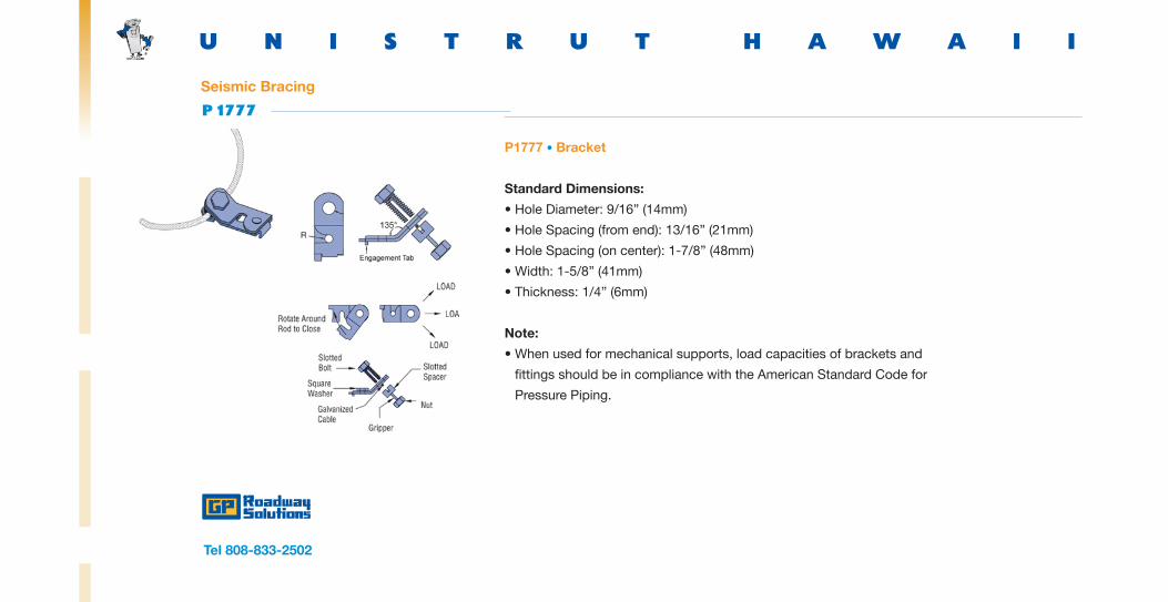
P1777 • Bracket
Standard Dimensions:
• Hole Diameter: 9/16” (14mm)
• Hole Spacing (from end): 13/16” (21mm)
• Hole Spacing (on center): 1-7/8” (48mm)
• Width: 1-5/8” (41mm)
• Thickness: 1/4” (6mm)
Note:
• When used for mechanical supports, load capacities of brackets and
fittings should be in compliance with the American Standard Code for
Pressure Piping.
P1777
U N I S T R U T H A W A I I
Seismic Bracing
Tel 808-833-2502

UP-BK • Pipe and Conduit Support
• The UniPier Rooftop support system provides a simple and versatile way
to support and manage pipe, tubing, conduit, HVAC systems, and the like.
The UniPier system supports without roof surface penetration and allows
the parts to remain off the surface.
Materials:
• Unistrut pipe clamps, unless noted, are punch-press made from hot-rolled,
pickled and oiled steel plates, strip or coil, and conform to ASTM
specifications A1008, A575, A576, A635, or A36. The fitting steel also
meets the physical requirements of ASTM A1011 SS GR 33. The pickling of
the steel produces a smooth surface free from scale. Many items are also
available in stainless steel.
UP-BK
U N I S T R U T H A W A I I
Roof Mounted Support
Tel 808-833-2502

I N D U S T R I E S
M I R O

6-H Base P • Duct + Cable Tray Support
Specifications:
• Load: Not to exceed 150 pounds/base
• Material: Base is made of polycarbonate plastic
and componenets are hot dip galvanized steel.
• Weight: Each base weighs 2.5 pounds
6-H Base P
M I R O I N D U S T R I E S
Roof Mounted Support
Tel 808-833-2502

8-H-DB Base P
M I R O I N D U S T R I E S
8-H DB Base P • Duct + Cable Tray Support
Specifications:
• Load: Not to exceed 350 pounds/base
• Material: Base is made of polycarbonate plastic
and componenets are hot dip galvanized steel.
• Weight: Each base weighs 4.5 pounds
Roof Mounted Support
Tel 808-833-2502

8-H-SB Base P
M I R O I N D U S T R I E S
8-H SB Base P • Duct + Cable Tray Support
Specifications:
• Load: Not to exceed 350 pounds/base
• Material: Base is made of polycarbonate plastic
and componenets are hot dip galvanized steel.
• Weight: Each base weighs 5.5 pounds
Roof Mounted Support
Tel 808-833-2502

Mechanical Supports
M I R O I N D U S T R I E S
Mechanical Supports •
Duct + Cable Tray Support
Heavy Duty
Light Duty
Roof Mounted Support
Tel 808-833-2502

6-DS P • Duct + Cable Tray Support
6-DS P
M I R O I N D U S T R I E S
Roof Mounted Support
Tel 808-833-2502

S Y S T E M S
G R I P P L E

Size Weight Range SWL (safe working load)
Gripple Hangers: Standard Product Range
No1 0 - 25 lbs 25 lbs
No2 22 - 100 lbs 100 lbs
No3 100 - 200 lbs 200 lbs
No4 200 - 495 lbs 495 lbs
No5 495 - 715 lbs 715 lbs
Gripple Hangers: Stainless Product Range
No2 0 - 100 lbs 100 lbs
No3 100 - 200 lbs 200 lbs
Fasteners
G R I P P L E
General Support
Tel 808-833-2502

Introduction
Gripple Seismic Bracing Systems are specifically designed and engineered to brace and secure
nonstructural equipment and componenets within a building or stucture to minimize earthquake
damage to suspended components.
Gripple Seismic Bracing Systems are ideal for use on nonstructural components and equipment
requiring seismic design, such as in essential facilities that are required for emergency operations
in the aftermath of an earthquake.
Advantages
• Complete pre-engineered systems
• No field swaging of cables
• Up to ten times faster to install
• No tools required
• Color coding allows easy field verification
• New or retrofit installations
• UL NEBS GR 63 Core Certification
Fasteners
G R I P P L E
Longitudinal Bracing
Seismic Bracing System
Seismic Bracing System Contents
Tel 808-833-2502
Seismic Bracing

HeadquartersO‘ahu • Honolulu660 Mapunapuna StreetHonolulu, Hawai‘i 96819Tel 808-833-2502Fax 808-836-1496
Neighbor Island LocationsMaui • Kahului153A Alamaha StreetKahului, Maui, Hawai‘i 96732Tel 808-873-7461Fax 808-872-9794
Big Island • Kona74-5489 Loloku Street, Bay AKailua-Kona, Hawai‘i 96740Tel 808-329-3684Fax 808-329-3694
Kaua‘i • Lihue3018 Aukele StreetLihue, Kaua‘i, Hawai‘i 96766Tel 808-245-9680Fax 808-245-6924