u. s. tool & die, inc.telephone (412) 487-7030 u. s. tool & die, inc. 4030route8 0...
TRANSCRIPT
TELEPHONE (412) 487-7030
U. S. TOOL & DIE, INC. 4030ROUTE8 0 ALLISONPARK.PENNSYLVANIA 15101
THERMAL-HYDRAULIC REPORT
SPENT FUEL STORAGE RACKS INDIAN POINT UNIT NO. 3
8721-00-0104
PREPARED FOR
NEW YORK POWER AUTHORITY 123 MAIN STREET WHITE PLAINS, N.Y. 10601 SPECIFICATION NO. FHS-01
AREVISION NO. 00
Not A Design Change REVISION 1 Jan. 1988 PREPARED BY DATE 1112_01_f.
REVIEWED BY DATE ,,/2.'/7
APPROVED By DATE ,'' Mana r of Engineering
APPROVED B DATE /,/2 t/d' 7 ai an Manager
901040276 81220 PDR ADOCK 050002B6 P PNU
THERMAL-HYDRAULIC REPORT SPENT FUEL STORAGE RACKS INDIAN POINT UNIT NO. 3
8721-00-0104 NOVEMBER 1987
REVISION 1 JANUARY 1988

REVISIONS
1. General Editorial Comments by NYPA IPO-87-60, and UST&D A Document 8721-00-0183
TABLE OF CONTENTS
Page
1.0 References 1
2.0 Abstract 3
3.0 Introduction 4
4.0 Detailed Analysis and Results 9
4.1 Introduction 9
4.2 Decay Heat Loads for the Spent Fuel Pool 9
4.3 Pool Thermal Inertia and Heat-Up Rates 10
4.4 Natural Circulation Cooling of the 12 Spent Fuel
4.5 Gamma Heating of the Reqion 1 Fuel Box 16 Walls, Poison and Water box
4.6 Poison Temperatures and Stginless Steel 17 Temperatures
5.0 Conclusions 18
6.0 Appendices 19
1.0 References
Al. Arya, A. P., Fundamentals of Nuclear Physics, Allyn and Bacon Inc., Boston, MA, 1966.
BI. Indian Point Unit No. 3, FSAR Update Table 3.2-4, Letter NYPA, F.W.Gumble to R.Linder, dated Aug. 18, 1987.
Dl. UST&D Drawing 8721-1, Rev. 1, June 1987 "Plan Arrangement of Spent Fuel Storage Racks."
D2. Dailey, J. W. and D. R. F. Harleman, Fluid Dynamics, Addison-Wesley Publishing Co., Reading, MA, 1966.
El. Eckert, E. R. G. and R. M. Drake, Heat and Mass Transfer, 2nd Edition, McGraw-Hill, New York, NY, 1959.
E2. El-Wakil, Nuclear Heat Transport, International Textbook Company, New York, NY, 1971.
GI. Westinghouse Electric Company Drawing Figure 3.2-31 "Fuel Assembly Outline". FSAR Update for Indian Point #3.
Kl. Kays, W. M. and A. L. London, Compact Heat Exchangers, 2nd Edition, McGraw-Hill, New York, NY, 1964.
K2. Kreith, F., Principles of Heat Transfer, 2nd Edition, International Textbook Company, Scranton, PA, 1968.
MI. Baumeister and Marks, Standard Handbook for Mechanical Engineers, 7th Edition, McGraw-Hill, New York, NY, 1967.
Ni. NRC Branch Technical Position ASB 9-2, "Residual Decay Energy for Light Water Reactors for Long-Term Cooling," Standard Review Plan, Section 9.1.3 and Section 9.2.5, Rev. 2, 1981.
P1. Perkins, J. R. and R. W. King, "Energy Release from the
Decay of Fission Products, "Nuclear Science and
Engineering, Vol. 3, Page 726, 1958.
Si. Technical specification for nuclear safety related
maximum density spent fuel storage racks for Indian
Point Unit No. 3, Specification No. FHS-01, Rev. 0.
S2. Streeter, Victor, Editor, Handbook of Fluid Dynamics,
McGraw-Hill, New York, NY, 1961.
T2. Lederer, C. M., J. M. Hollander, and I. Perlman, Table
of the Isotopes, 6th Edition, J. Wiley and Sons,
New York, NY, 1967.
T3. Chemical Engineering/Desk Book Issue/ April 14, 1969.
T4. Giedt, Principles of Engineering Heat Transfer,
D. Van Nostrand Company, 1957.
U1. Seismic Analysis Report, Spent Fuel Storage Racks for
Indian Point-Unit 3, 8721-00-0033 August, 1987.
Vi. BORAL, THE NEUTRON ABSORBER, Brooks and Perkins,
Product Performance Report 624, 19R3.
Wi. General Electric Technical Paper 22A5866.
2.0 Abstract
The thermal-hydraulic analysis for the new high density U.S. Tool & Die racks for Indian Point Unit No. 3 considers: (1) the decay heat for the spent fuel pool and the resulting pool temperatures, (2) the spent fuel pool heat-up rate and time until pool boiling following a loss of spent fuel pool cooling, (3) the natural circulation cooling of spent fuel and (4) the gamma heating and natural circulation cooling in the fuel assembly water boxes.
3.0 Introduction
3.1 The scope of the analysis covers Technical Specification (Section 8) and revisions of the New York Power Authority Specification FHS-Ol, Rev. 0 and includes the following:
a. Computation of decay heat loads for the spent fuel pool in accordance with the NRC's SRP 9.1.3 and SRP 9.2.5, Branch Technical Position ASB 9-2.
b. Temperature changes and heat-up rates for the
loss of spent fuel pool cooling accident under normal refueling and full core off-load conditions.
c. Recirculation flow characteristics in the hottest and average stored spent fuel assemblies to determine local coolant temperature changes and peak clad
temperatures. A local path (path 1) and an underrack path (path 2) are examined.
d. Investigation of gamma heating in the water boxes of Region 1 containinga fupl assemb -ly to assure adequate
coolant flow exists and determination of the temperature distributions in the water box , ar~d poison wall.
3.2 Methods and Assumptions used in the Thermal-Hydraulic Analysis
The methods used for analyzing the thermal-hydraulic aspects of the spent fuel pool involve relatively uncomplicated correlations for friction factors, loss coefficients, and heat transfer coefficients that make a detailed computer analysis unnecessary. Further simplifying but conservative assumptions reduce the mathematical complexity to the point where hand calculations or programmable calculators are all that are required.
3.3 The design criteria used for the thermal-hydraulic analysis of the spent fuel pool for Indian Point Unit 3 are in accordance with the NRC "OT Position for Review and Acceptance of Spent Fuel Storage and Handling Applications", issued April 14, 1987. Additional conditions are given by Specification FHS-01, Rev. 0 for the Spent Fuel Storage Racks, NYPA's August 25, 1987 letter from C. Tessmer to J. Rhoden and NYPA's November 2, 1987 letter from C. Tessmer to F.E. Witsch.
Based on the NRC Position Paper, the specifications and the two letters, the following are established as design bases
or requirements:
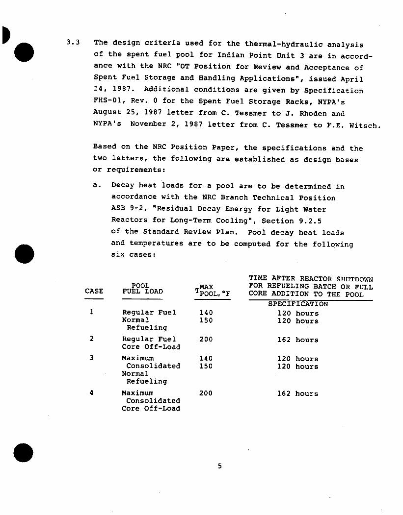
a. Decay heat loads for a pool are to be determined in accordance with the NRC Branch Technical Position ASB 9-2, "Residual Decay Energy for Light Water Reactors for Long-Term Cooling", Section 9.2.5 of the Standard Review Plan. Pool decay heat loads and temperatures are to be computed for the following
six cases:
TIME AFTER REACTOR SRTTTDOWN POOL MAX FOR REFUELING BATCH OR FULL CASE FUEL LOAD TPOOL,OF CORE ADDITION TO THE POOL
SPECIFICATION 1 Regular Fuel 140 120 hours
Normal 150 120 hours Refueling
2 Regular Fuel 200 162 hours Core Off-Load
3 Maximum 140 120 hours Consolidated 150 120 hours
Normal Refueling
4 Maximum 200 162 hours Consolidated
Core Off-Load
b. To ensure that adequate time exists for an alternate
cooling method to be implemented in the event of a
loss uf spent fuel pool cooling capability accident,
the heat-up rate is calculated and the time required
for pool boiling to occur is determined.
c. Coolant flow rates, temperature increases, and peak
clad temperatures are to be determined for worst case
conditions (i.e. high pressure drops and low heat
transfer conditions for fuel assemblies, high bundle
decay heat, etc) to verify that boiling shall not
occur.
d. The effect of gamma heating in the cell box and inter
cell spaces between fuel assemblies of Region 1 is to
be analyzed to assure that gammna heating shall not cause
boiling in these positions. Adequate flow must be
established to preclude the possibility of trapping air
or steam anywhere in the fuel racks.
e. Coolant flow paths and sparger locations affecting the
analysis shall be identified.
3.4 As noted in the design bases, conservative assumptions are
employed for evaluations of all coolant and clad tempera
tures. Some additional assumptions used for the thermal
and hydraulic analysis of the spent fuel pool are as
follows:
a. The thermal inertias of the concrete walls and the
coolant and piping outside the pool boundaries are
neglected in the transient heat-up analysis.
b. The pool surface is not assumed to mix to a lower
pool bulk temperature in the heat-up analysis
following the loss of spent fuel pool cooling
accident. The time calculated to boil is based on
the pool maximum bulk temperature and not a lower pool average temperature.
6
c. All decay energy is assumed to be absorbed in the fuel and surrounding coolant for the hot assembly natural circulation analysis. (In reality, some gamma radiation will be absorbed in the adjacent cell boxes and poison).
d. The gamma decay heat absorbed in the Region 1 cell box wall is taken to be proportional to the mass densities of the materials in the spent fuel pool. (In reality, most of the gamma radiation never leaves the fuel assembly due to strong uranium attenuation.) Gamma heating proportional to the mass fraction is roughly equivalent to the assumption of uniform gamma flux in the repeating unit cell.
e. A circulation flow path (path 2) from the South wall or downcomer to a position along the North wall-is assumed for the hottest assembly. This derates the flow to the hottest assembly since flow down the three remaining walls is. also possible.
f. The average hot assembly generates 1.84xl10 BTU/HR based on refueling 120 hours after reactor shutdow~n. A conservative sinusoidal axial power distribution
was assumed where the clad hot spot temperature
rise factor is about 1.57 times the average tempera
ture rise.
g. To conservatively predict the flow rates to the hot assembly the dominant pressure drops are over estimated by factors of 1.5 for the fuel assembly pressure loss and 2.0 for the under rack pressure losses.
h. Material properties (e.g. thermal conductivities,
densities, and specific heats) are generally assumed to be independent of temperature and are evaluated at some specified (average, inlet, or surface) tem
perature.
3.5 The major areas of concern in the thermal-hydraulic analysis are to verify that the clad and coolant temperatures do not become high enough to cause boiling. In the event of the loss of spent fuel pool cooling accident, the heat-up rate must be slow enough to allow an alternate coolant system to be connected and operating before pool boiling occurs.
4.0 Detailed-Analysis and Results
4.1 In this section, we present an analysis overview for the calculation summaries that follow. Decay heat fractions are computed according to NRC Branch Technical Position
'~~ASB-2 standards and are presented in Section 4.2. Total heat loads for the normal refueling and full core off-load conditions for intact fuel storage (Case 1 2) and consolidated fuel storage (Cases 3 & 4) are then calculated. The thermal inertia of the spent fuel pool (SFP) is computed in Section 4.3. Heat-up rates and the time taken for the pool water to reach 212OF following a loss of spent fuel pool cooling accident are found. Make-up rates at pool boiling are also determined in this section.
Section 4.4 contains the natural circulation cooling analyses. A local recirculation path (path 1) and a more complete under-rack path (path 2) are considered. Clad and coolant temperature distributions are determined for these worst case analyses. In Section 4.5 Region 1 gamm a heating of the cell box walls and poison "Slabs" adjacent to the hottest assembly is investigated. The temperature distributions in the stainless steel cell wall, poison cell box interface are determined in Section 4.6.
4.2 Decay Heat Loads for the Spent Fuel Pool
The NRC Branch Technical Position ASB 9-2 is used to compute the decay heat fractions for the Indian Point Unit 3 spent fuel pool (SFP). For cooling times greater than
10 7sec. (116 days), ASB 9-2 does not specify a fission product decay uncertainty factor, but SRP Section 9.1.3
7 recommends a value of 0.1 for times > 10 secs. and is used here.
Based on ASB 9-2 and the six cases outlined in the design bases, the decay heat fractions and the SFP decay heat
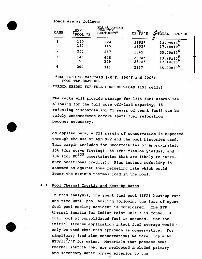
loads are as follows:
CASE , SHUTDOWN* OFNA'S dfOTAL, BTU/HR
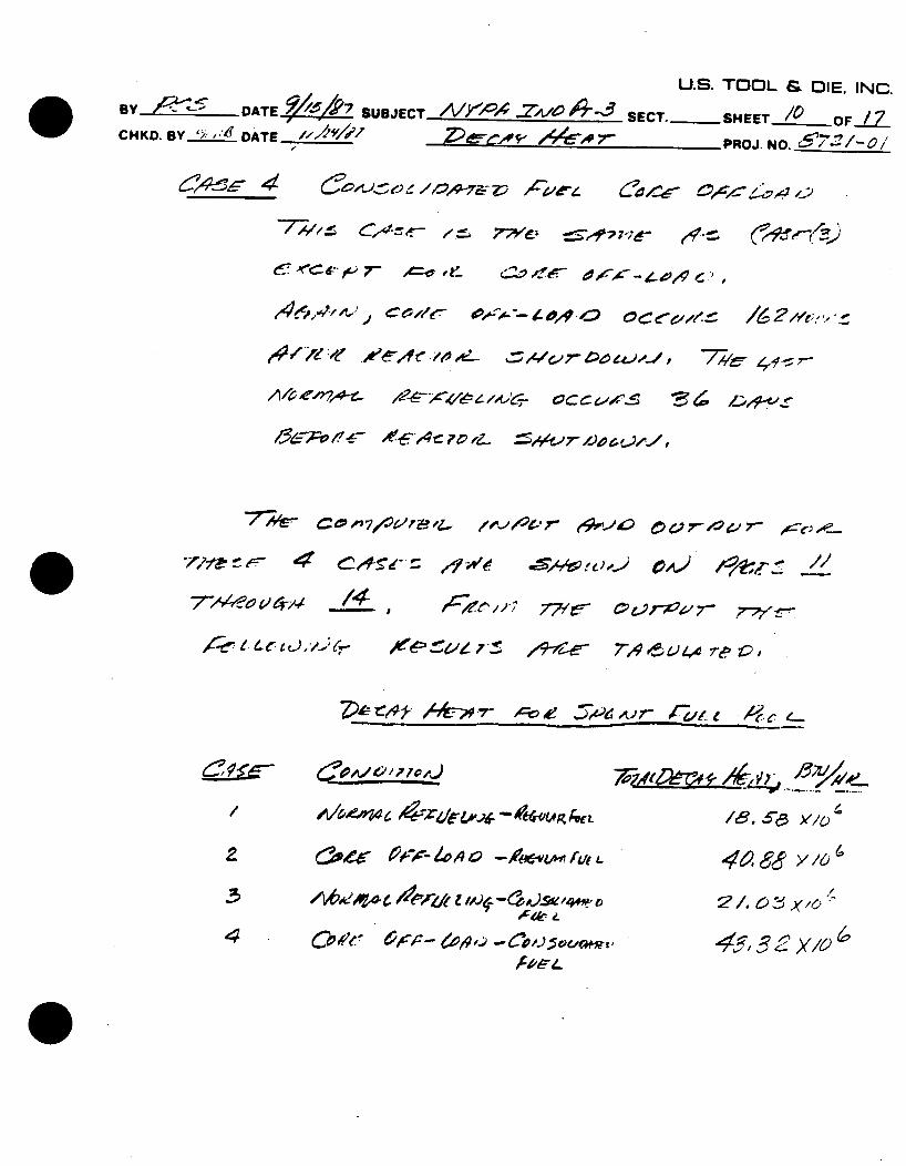
1 140 324 1152* 13.99x10 6
150 145 1152* 17.48x106
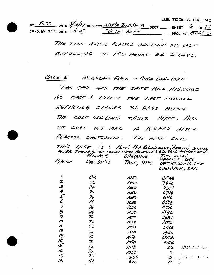
2 200 267 1345 35.00x10 6
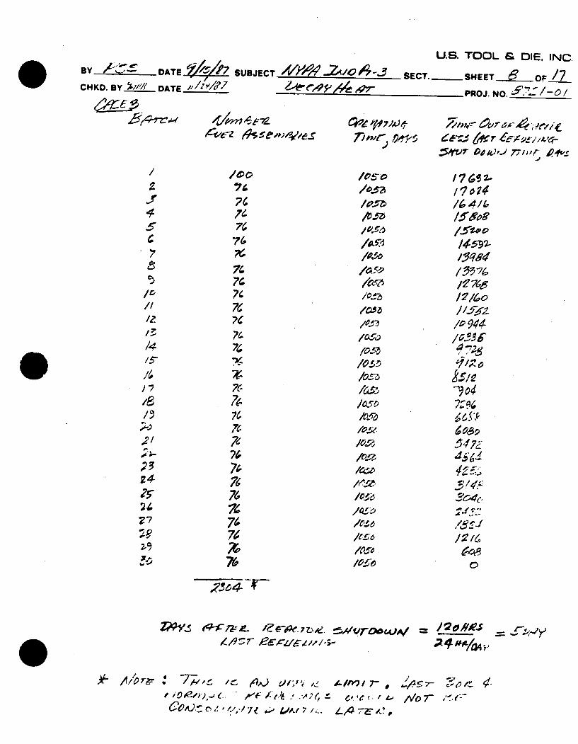
3 140 648 2304* 13 99x10 6
150 246 2304* 17.48x106
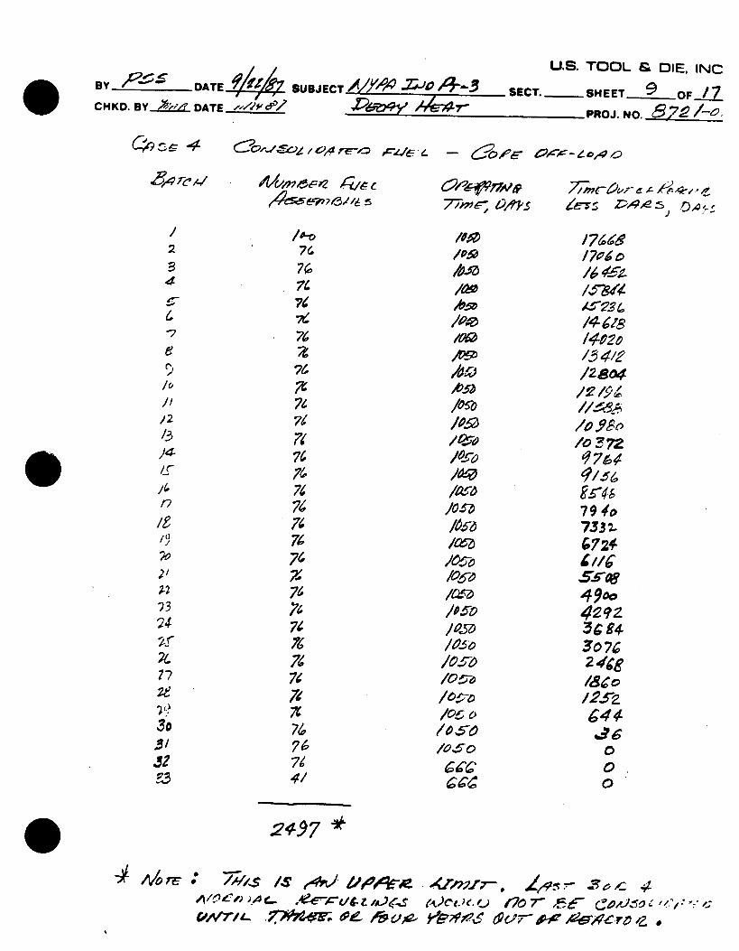
4 200 341 2497 35.00x10 6
*REQUIRED TO MAINTAIN 140*F, 150 0 F and 200*F POOL TEMPERATURES
**ROOM NEEDED FOR FULL CORE OFF-LOAD (193 cells)
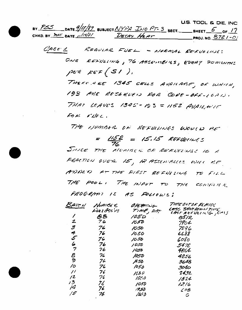
The racks will provide storage for 1345 fuel assemblies. Allowing for the full core off-load capacity, 15 refueling discharges (or 25 years of spent fuel) can be safely accommodated before spent fuel relocation
becomes necessary.
As applied here, a 25% margin of conservatism is expected through the use of ASB 9-2 and the pool histories used. This margin includes for uncertainties of approximately 10% (for curve fitting), 5% (for fission yields), and 10% (for PU239 uncertainties that are likely to introduce additional credits). Plus instant refueling is assumed as against some refueling rate which would lower the maximum thermal load in the pool.
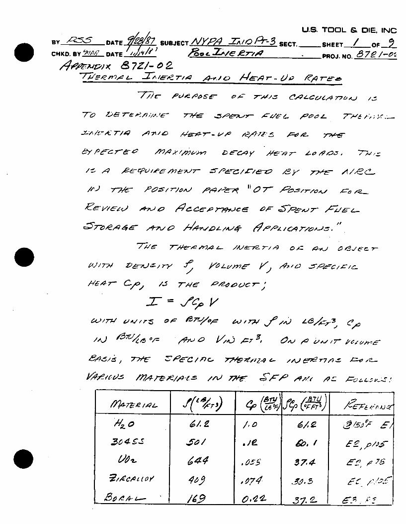
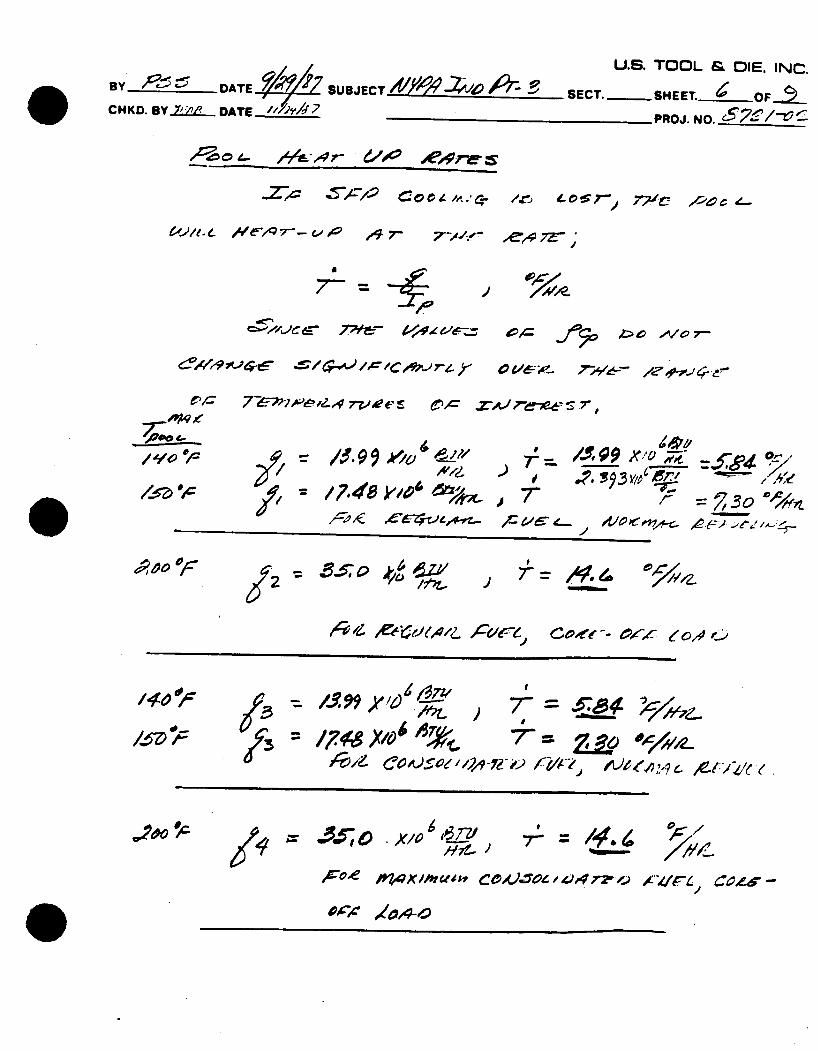
4.3 Pool Thermal Inertia and Heat-Up Rates
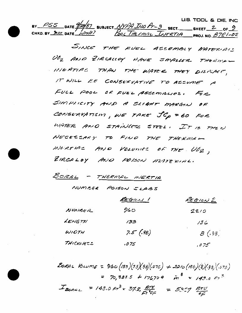
In this analysis, the spent fuel pool (SFP) heat-up rate and time until pool boiling following the loss of spent fuel pool cooling accident is considered. The SFP thermal inertia for Indian Point Unit 3 is found. A full pool of consolidated fuel is assumed. For the initial license application intact fuel storage would only be used thus this approach is conservative. For simplicity (and also conservatism) we take cp = 60
BTU/ft 3/0F for water. Materials that possess some thermal inertia that are neglected included primary
and secondary water piping exterior to the in
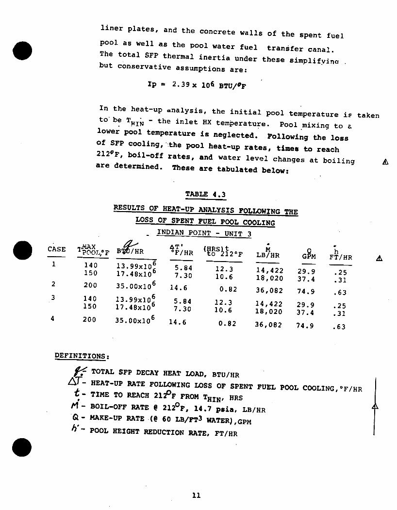
liner plates, and the concrete walls of the spent fuel pool as well as the pool water fuel transfer canal. The total SFP thermal inertia under these simplifyina but conservative assumptions are:
Ip = 2 .39x 106 BTU/OF
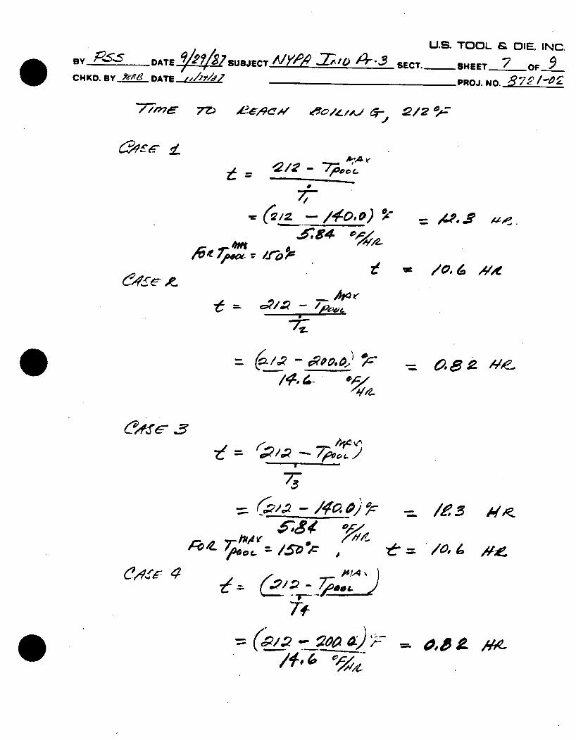
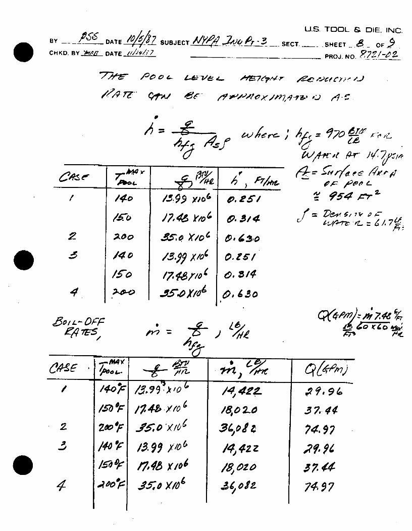
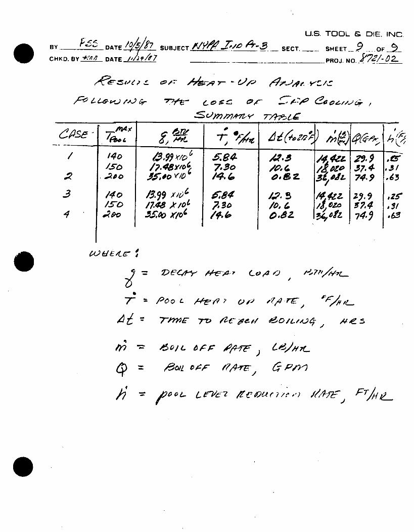
In the heat-up analysis, the initial pool temperature is taken to be T - the inlet HX temperature. Pool mixing to a MI1N lower pool temperature is neglected. Following the loss of SFP cooling,'the pool heat-up rates, times to reach 2120F, boil-off rates, and water level changes at boiling are determined. These are tabulated below:
TABLE 4.3
RESULTS OF HEAT-UP ANALYSIS FOLLOWING THE LOSS OF SPENT FUEL POOL COOLING
INDIAN POINT - UNIT 3
B~iRAT~ ( RSj 2 B7 _R 0F/HR o 120F LB/HR
13.99x10⁶ 5.84 12.3 14,422 17"48x106 7.30 10.6 18,020 35.00x10 6 14.6 0.82 A nai13. 99x10 6
17.48x10⁶
35. 00x106
5.84 7.30
14.6
12.3 14,422 10.6 18,020
0.82 36,082
29.9 37.4
74.9
9.9 7.4
4.9
2 3
7
h FT/HR
.25 .31
.63
.25
.31
.63
DEFINITIONS:
/- TOTAL SFP DECAY HEAT LOAD, BTU/HR AT- HEAT-UP RATE FOLLOWING LOSS OF SPENT FUEL POOL COOLING,OF/HR - TIME TO REACH 212PF FROM THIN, HRS
/- BOIL-OFF RATE @ 212OF, 14.7 psia, LB/HR Q- MAKE-UP RATE (@ 60 LB/FT3 WATER),GPM
b*- POOL HEIGHT REDUCTION RATE, FT/HR
CASE
1
2
3
4
TP1MAX POOL0 F
140 150
200
140 150
200
Iv vv
- --
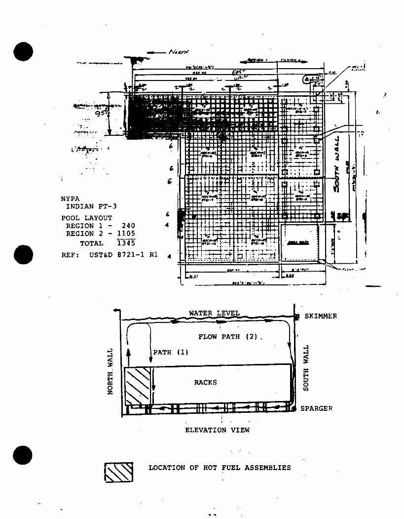
NYPA INDIAN PT-3
POOL LAYOUT REGION 1 - 2 REGION 2 - 11
TOTAL f3,
REF: UST&D 87,
WATER LEVEL
FLOW PATH (2)
PATH (1)
RACKS
|;.. . , ,n 4 4A
SKIMMER
0
SPARGER
ELEVATION VIEW
LOCATION OF HOT FUEL ASSEMBLIES
5. For the local path (path 1) the fuel assembly inlet
temperature is taken to be the hottest pool bulk
temperature. For path (path 2) the inlet temperature
is the average for the pool.
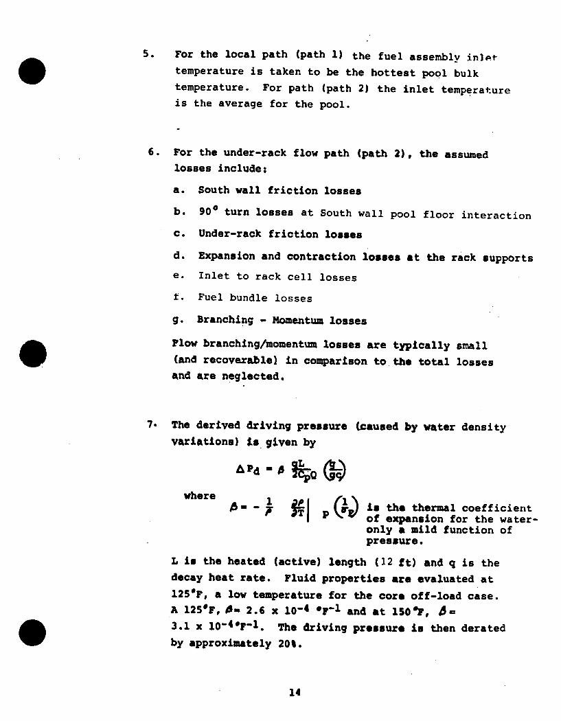
6. For the under-rack flow path (path 2), the assumed
losses include;
a. South wall friction losses
b. 90* turn losses at South wall pool floor interaction
c. Under-rack friction losses
d. Expansion and contraction losses at the rack supports
e. Inlet to rack cell losses
t. Fuel bundle losses
g. Branching - Momentum losses
Flow branching/momentum losses are typically small
(and recoverablel in comparison to the total losses
and are neglected.
7. The derived driving pressure (caused by water density
variations) Ls given by
APd L ~
where - - TI (Q is the thermal coefficient
I ~ of expansion for the wateronly a mild function of pressure.
L is the heated (active) length (12 ft) and q is the decay heat rate. Fluid properties are evaluated at
125*F, a low temperature for the core off-load case.
A 125*F, 0m 2.6 x 10⁻⁴ OF-1 and at 150"F, A=
3.1 x 10-49F-l. The driving pressure is then derated
by approximately 20%.
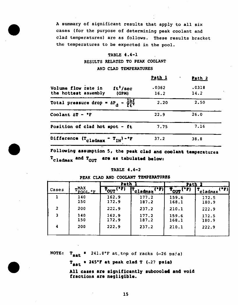
A summary of significant results that apply to all six
cases (for the purpose of determining peak coolant and
clad temperatures) are as follows. These results bracket
the temperatures to be expected in the pool.
TABLE 4.4-1
RESULTS RELATED TO PEAK COOLANT
AND CLAD TEMPERATURES
Volume flow rate in the hottest assembly
ftI/sec (GPM)
Path 1
.0362 16.2
Path 2
.0318
14.2
Total pressure drop - APd - lbf 2.20 2.50
Coolant AT - OF 22.9 26.0
Position of clad hot spot - ft 7.75 7.16
Difference (Tcladmax - TIN)-OF 37.2 38.8
Following assumption 5, the peak clad and coolant temperatures
Tcladma x and TOUT are as tabulated below:
TABLE 4.4-2
PEAK CLAD AND COOLANT TEMPERATURES
NOTE: Tsat U 241.8 0F at-top of racks (-26 vsia)
Tsat U 245"F at peak clad T (-27 psia)
All cases are significantly subcooled and void fractions are negligible.
Since the actual flow paths will be complicated combinations of local and under-rack paths, the temperatures will not exceed those indicated. The indicated temperatures are much lower than the 700-8000 F which is the lower bound for low temperature sensitization of austenitic stainless steel.
4.5 Gamma Heating of the Reaion 1 Fuel Box Walls.Poison & Water Box
In this analysis, gamma heating of the Region 1 fuel box walls, poison and water box is investigated.
Fission product decay accounts for virtually all residual heat in the spent fuel pool with minimum cooling times ts :' 5 days. At this time, a realistic but upper limit on the gamma fraction is 0.62, based on reference P1, the primary reference for the NRC position standard ASB 9-2, Reference Nl.
A typical 1 MeV electron will travel approximately 0.016" in the U02 fuel. Thus, a110- electrons will be stopped in the fuel or surrounding clad and coolant. A typical, but higher than average, 1 MeV gamma ray has a mean free path of approximately 0.56" in the U02 fuel - comparable to the pellet diameter .373". Therefore, the fuel will not stop all the gamma radiation emitted by the decaying fission products. It will then be conservative to assume the following when estimating the energy deposition in the fuel box, poison, and water box:
1. The fuel box is located within an infinite array of hottest assemblies - each generating 1.84 x 10⁵ BTU/hr, 62% of which is gamma. This is based on decay heat level 120 Hours After Reactor Shutdown.
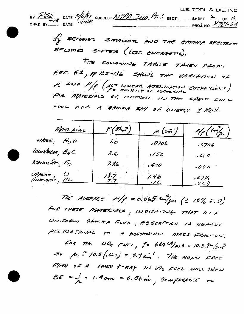
2. The gamma energy absorbed in a unit cell comprised of one fuel assembly, one fuel box, and four Poison "Slabs" is proportional to a given material's mass fraction. This is roughly equivalent to the assumption of uniform y-flux since v/p is approximately constant for all materials at a given gamma energy.
3. Water in the water box must remove gamma heat due to energy depositions in the water box wall, and the water box itself.
The flow rate in the water box is determined by equating the driving head to the loss head. The coolant temperature corresponding to this flow rate is then computed and is less than the boiling temperature of the coolant.
4.6 Poison Temperatures and Stainless Steel Temperatures
In this calculation, Region 1 temperature distributions in the poison are determined. Heat source terms (due to gamma irradiation) follow the same conservative assumptions used in Section 4.5. The maximum temperature of the poison is seen to be less than the boiling temperature of the coolant hence no boiling will occur in this region. Region 2 temperatures will be lower than Region 1 because of lower power fuel assemblies.
The temperature gradient in the stainless steel across the fuel box interface is modeled using a steady-state,1 l-D, heat conduction equation. The maximum temperature difference is limited to less than 2.5*F and is of a magnitude which should produce negligible thermal stresses in the stainless steel walls of the rack for both Region 1 and Region 2.
5.0 Conclusions
The detailed thermal-hydraulic analyses described in Section 4 address the concerns, inte 'nt and design bases of the NRC's Position Paper "OT Position for Review and Acceptance of Spent Fuel Storage and Handling Applications" and the New York Power Authority Specification FHS-01, Rev. 0.
Based on these analyses, our professional staff has concluded that the spent fuel pool for Indian Poinit Unit 3 can be adequately cooled in accordance with the suggested regulatory standards of the Nuclear Regulatory Commission and comply with specifications outlined by New York Power Authority for spent fuel racks described in this report and loaded with spent fuel as indicated in this report.
6.0 Appendices
This section contains the four detailed thermal-hydraulic analyses attached as appendices. They are as follows:
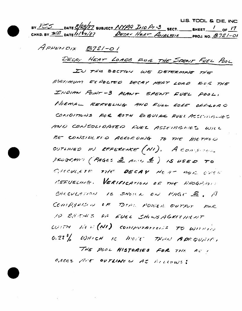
Calc. 8721-01 --- "Decay Heat Loads for the Spent Fuel Pool"
Calc. 8721-02 "Pool Thermal Inertia and Heat-Up Rates"
Calc. 8721-03 "Natural Circulation Cooling of the Spent
Fuel"
Calc. 8721-04 --- "Gamma Heating of the Region 1 Fuel Box Walls, Poison "Slabs", Water Box".
U.S. TOOL & DIE. INC
BY DATE4 / iL SUBJECT A/' -. /0icA- SECT. SHEET OF __ CHKD. BY D ATE//('d'7 4t'69 rir., , PROJ. NO.8 2E/-o/
/d/::- ox 7e:/-o /
~~~~~4e r ,- 145 ~ A'z. AC0 4
0444p- 1-5.,10 C~ 6W - a-Z- 4>
/:'2A:// y:,Z, -X- C4 IA. 4- ,IC'V IV COZ45A. 4,4 ",- ---- 0 /Z g 0-/
C.ZA/ ,L ,, /p ,.. -_ : " , . r ,c, , J6. - . A2 o_ ( -, ' ,.
CO 01 77 .5 ~EC~-V- ',174 * 4e9! 'F-s '... OC1e%. ~ '-. ~
- , .- e , 6 e. / ,
6 77CT CAoA o oc 4 73) 77.- ~ .:
,~4~ L - ,C 7%t ,4O~ . .,
V --. '4 Lz - PL) er=67-Aoi5- C--' /c'7.')U
,.z 2. /,, '.. , . / I:: r,, .. . 7-4 0 W= i4
." - - 4/ ~ToMe'€- ./& C, ' . -
U.S. TOOL & DIE. INC BY /Z"ATE42L7--,& fSUBJECT /Vk'i / O 4~l5 SECT.-SHEET___ CHKD. BY D'__°ATE ,,/ / 7 4R/ 4
Nr -if,2 p . /-/
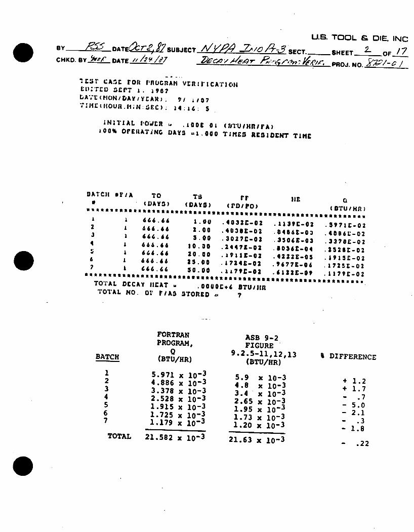
rlsr CA.C ronF Il'flGnAI VrIf[I'ICATIon El):'rD -C1T . a 907 LA*:t(HON/DAYIYCAR). 91 ;i07 "S.ItlC i{OUR.1;4:£EC). 14:16: 5
INITIAL POWELR w .100E Ol (fJTUInlFA) 100% OFEIATiNG DAYS =1.0o TIMES RESIDENT TIME
BATCH FI/A TO TS FF liE Q ( DAYS) (DAYS) (roDIPO) (BTU/HNn)
1 1 666.66 1.00 .4032C-02 .1131C-02 .3971E-02 2 1 666.66 2.00 -4038E-02 .04869-03 .4086L;-02 3 1 660.66 5.00 .3027C-02 .350&E-03 .3378E-02 4 1 666.66 10.00 .24471-02 .8036-04 .25281-02 5; 1 666.66 20.00 .1911E-02 .4222E-05 .153C02 6 A 666.66 25.00 .1724Z-02 .9677-06 .1725E-02 7 1 666.66 50-00 .1179E-02 4613aE-09 .1179E-02
TOTAL DECAY HEAT . .0000C,6 BTU1i1a TOTAL NO. Or FIA3 STOnED . ?
BATCH
FORTRAN PROGRAM,
Q (BTU/HR)
1 5.971 x 10- 3
2 4.886 x 10- 3
3 3.378 x 10⁻³ 1 2.528 x 10⁻³
1.915 x 10⁻³ 1.725 x 10:3 1.179 x 10 3
TOTAL 21.582 x 10⁻³
ASB 9-2
FIGURE 9.2.5-11,12,13 (BTU/HR)
5.9 x 10⁻³ 4.8 x 10⁻³ 3.4 x 10- 3
2.65 x 10⁻³ 1.95 x 10 - 3
1.73 x 10⁻³ 1.20 x 10⁻³
21.63 x 10⁻³
% DIFFERENCE
1.2 1.7
.7 5.0 2.1
.3 1.8
- .22
S2 . . . L I = N C BYSUBJECT(DATE SUBJ //ECT!/O ' SECT.-SHEET /7OF-_ CHKD. BY2!F DATE /
O. No. ,
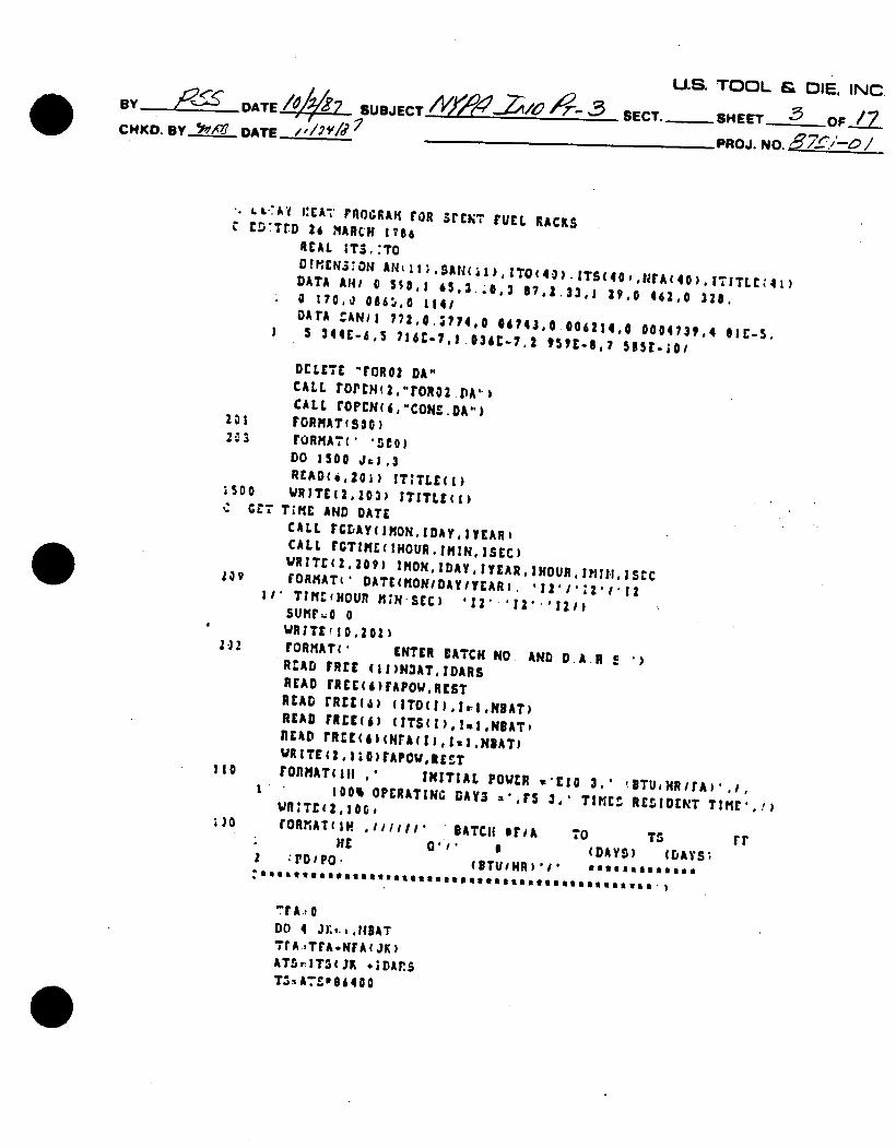
LC' I:EA'' roGRAIm raR srENT rUEL RACKS C ECTTrD 26 NARCH 1986
REAL !TS.:TO D!KENZ:ON1 AN(ic;.SAN(ii),IT O (04).ITS(40, A(40) I,ITLC41) DATA A1/ 0 553,1 65,3..0,3 87.1.33,1 Z9, 462.0 328, O 1700 0865,0 1141 DATA CAN1! 772.0.3774,0 06743,0.006214,0 0004731,4 ICI-5, I 5 344E-6,5 716E-7,1.036C-7,2 959t-$o? 56sr-jo/
DELETE "rOR02 DA" CALL rOPCN(2,"roRo2DA.., CALL rOPCNC6,"CONS.DA..)
201 FORMATfS30) 2C3 rORNATC( 'SCO)
DO 1500 Jai,3 REAO(6,201) IT;TLE()
;So0 'RITE(2,103) ITITLE(s)
C GCT TIME AND DATE CALL rGDAYCIHON,IDAYIYEARI CALL rCTIKE(IHOURIMINISEC) VRITr(i,zog) IMONIDAYIYEARIHOURIII.I,ISrC
209 fORMAT(' DATE(RONIDAYIYEAR). I2 / 2 I/* TInreHOUn MINSEC) °12' 'i21
SUIfl.O 0 WRITE(10,202)
212 rORMAT(' rlyre.-.,n lu AND D.A R " READ FREE (II)N3AT,1DARS
READ (REcr()FAFOW,REST READ FrnEt6) (ITO(),iI.NBAT) READ rREg(S) (ITSCI),.!1.NAT, READ TREE(61(NA(I),IeIN8ATI WRITE, h10)FAPOWREET rORMAT1III * INITIAL POWER *'EIO 3,' !BTU,HRIrA)',j,
100% OPERATING DAYS .. rS 3.' TINC RESIDENT TIME,'!) Wf:TCQz,10o, rORMATtIH .iillI' BATCH reiA T0 TS rr
HE£ 011' 0 (n ve a-...
Z .PDIPO , (UTUINR)',i Batll es
'rA.,0 DO 4 J 1,.Ih,, AT TrA.,TFA.wrA~jK)
ATSrIT$(JK *;DAPS T5%A718d4400
as..
" = rr,%r-%i
U.S. TOOL & DIE. INC 8 y DT UJC SECT.-SHEET _____OF ''7 CHKD. BY 5 f '6' DATE _ ___ __d_ PROJ. NO.__-_-P,
A7 TOT( JK ; T04:ATO3i 400 BREST TSPTO-TST0
3UMK4 0 51U12,:0 4 CO 5 J:,",11
SUMi:;SUHtIANJI*eIP(rSAN(J)gTS) SUHISUII'.AK(J),CIPt-SAN(J) TPTO)
CON7Iflug AK,| 1
lrTS LT.1O000 Ael 2 rOPO=NrA JK 3(AK'SUt.SUM2 )120. COtt,:Cl.tZpc.! 91t.4tT0))e(tXP(o4 IIE.44T$)) 1U2J9,o00221'l0.?iCOCF
COETZ,:.i.gI,1( 3 41E-2T0)6:zpt.( 3 41C-6'TS ) FN2:9:10 0021710 71(2.O0?aCOCF2.0.007tCOE,) rDPOHt,:IIFA(JK)G(PU239,PN131) PO1a[RvrAPOW*(PDrOPDFOH9) WRITr(,10i)JKNrA(JK)ATOATS,PDpO,PDPONt.,7OER
101 rORlMAT(31,12,4z,13,21,F? 2.21.r? 2.3tII.4) sumrSumPpovwn
4 CONTINUE SUMmp:SUPI'i E.6 WR!TEi2,101)SUKp
:02 rORMAT(' ttitt
:tRosett'.p TOTAL DECAY MEAT &''9 4.-r.6 IT11/|IR. ) VRITE (2.I13)TrA 1ORMkT* *TOTAL NO. o rIAS STOR:D -'15) 3TOP END.
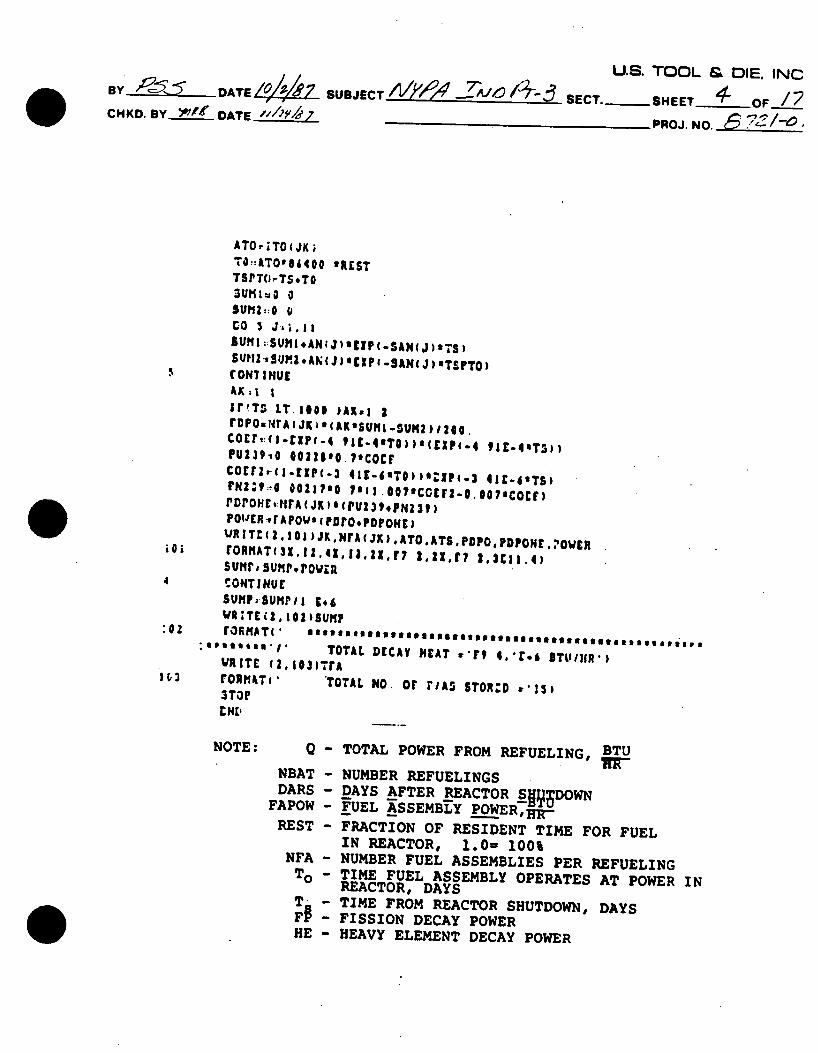
NOTE: Q - TOTAL POWER FROM REFUELING, BTU
NBAT - NUMBER REFUELINGS DARS - DAYS AFTER REACTOR Sll3DOWN
FAPOW - FUEL KSSEMBLY POWE RC, REST -FRACTION OF RESIDENT TIME FOR FUEL
IN REACTOR, 1.0= 100% NFA - NUMBER FUEL ASSEMBLIES PER REFUELING To - TIME FUEL ASSEMBLY OPERATES AT POWER IN REACTOR, DAYS T - TIME FROM REACTOR SHUTDOWN, DAYS
- FISSION DECAY POWER HE - HEAVY ELEMENT DECAY POWER
U.S. TOOL & DIE, INC By DATE ///j, SUBJECTA-Y/-4 7o 10-13 SECT.-RJSHEET N OF.-l CHKD. BY '~~"DATE_______? 4 r - PROJ. NO. 8 72 -
-,
/'&72 -;l:.(%S'/ 2'7"-/-4, eA ,a ec-
7,54/ /~ 7 -/ ,';~ 4 4/ 1'
A,/e c/v r
72/t:- 0,&/ e1~-4. 5 /t, ~ .
=. = /6 . -"
7?-'~ ~/~:'~;'/,~ C '~ e5P ,e&-~-4 '6 - 2 . '~-r~- ,~ ~
047,21?
-'O?,A z- ,
/ z 3
4 .7
8
/0
// ft
'-A
/4
7(0= 7' 76 74 74 7(
7' 76
7' 76
7-V f',i.
- I/,-. 'I 7- V 771! C .,'' .( _
9$ e '-> O,, W .,., ,
A L;.4
f64
304o
70¢
.?,40
I95.f 4
4-/
1,3.5
.o /955L,)2.eer e-I , ..
,47-- 77Y-5- oClIe15r
By DATE_ _
CHKD. BY *A/6'i DATE _______/7
U.S. TOOL & DIE. INC
SUBJECT___'____-'__-_- SECT._SHEET (o OF/7 S4,4- PROJ. NO. ____-0_
7zi~ 7b'~ ~4,c7~ ~ 672' -~ ~~4'47~CW/d ,ca t~ ~
,le~r4r4,-_ , /./ -4c)44- , Z ,.1
Je- .
ce),' cr 04,eo4/
C tOe ,e9 4 :
-l/
/
/7
//
/5 /62~4'#~~ ,,4v/ fl**
£~A~s 4aeoy.vi 4'9;,
48 74 76, 7( 7' 74 7'
7' 7
74
74 7, 41
/W11 /0-1
/W3
.06,4Z
66
6S46 7946
73 31
4 /(o 6'91
3684 /21-'24f
614
0. 0
s0%
'I
/ f) 1120 AAVVe!: ooe
A)/4 e ,o ora:e
U.S. TOOL & DIE. INC BY DATE_______ SUBJECT -4P1'? - ,'o,14-3 SECT. - SHEET_ oF I__7 CHKD. BY p' ._ DATE__ _2__ 1 e "' , -; 7- PROJ. NO. 5 72/-o/
A. Z&-;e 7-,- AAe-~ 56- tJ oO
7,7,Co;? 7- 7- --0Co e- C- #. 7 9 ?"
le-l ,- e 12-. ~ ~ ~ 'c-L~ ',Cf
7,2,c 6 r- 4 ,Ae~ eoo , 5
oV4..-- e-, F . /107 / e.f. . . c- o,-5
7 4 FC 7; 754 e~~A 11 0 c''e( J
4 ZT~?e:W e/9 0,r2 e oe Ce - c,
19 3) )
? ~~~~~~~~~r -..z -,,,, /,le h
U.S. TOOL & DIE,. INC BYZ - DATE 4/.7 SUBJECT MpO'?411't463 SECT. SHEET OF17 CHKD. BY 1///e DATE ___e_____ _ 0_ PROJ. NO.____ __0
/
6; 2
24 57
//
/4
29 eSr
-7' 7' 7'
7',
7' 7' 7': 'C
74 7':
7'6 7.
726 7 7
7' 7
74 74 7 76
7wl
C' ~ ~ ~ ~ ~ -M 7-/',!;, ,A ~ ,
/0-o
/o5
/645
/05e lose
/r 4,
A0 '
/ /Ao
/0 94,4
:5 , 77,
Di2 14599
15q,4
2:97
If76
BU.S. TOOL & DIE, INC Y DATE SUBJECT SECT. SHEET 2 OFJZT
CHKD. BY 04-W DATE __________ _ _ _" ____PROJ. NO. 87 - /- - '.
/ V,4 r-i- ,e,' -L -~w~ -~ /~-0,4 0
/
2
4
J
"7
2
/.)
'3
24 23. 94
,5/
76
7' 7(
76
16
7'
76 7' 76 7' 7' 7' 7'
7'
7' 7' 7'. 7' 7
74
74 74,
76 4/
/00o
/0-V /050
/5V
/Po
/A-Z
/05/0-0 /Q7.
/0-63
14'5-'
2€97 *
17/.1 /s O4:,, .Q' .r- Z,, -$ Sl,,= 4 #Vc.).W' , &4, nt_ - C"d~ t ., ()C O.C ) (70 " .,S. - O J s ,/'::. .
Ze~f Z 445 e
176 o
/4 $/8 /5 4/55
128404
3 !72 764
79 4o 7-336724 4116,
4900 4219Z 3cg4. 3o 7,
/2.r2 644
0
0
U.S. TOOL & DIE, INC. BY 9,I DATE_____ _E SUBJECT Ay-,c24 -7A/t-.-,3 SECT._SHEET O OFJ17
CHKD. BY DATE____ Z) 4 0 V 1-o7 PROJ. NO. i--
744~a U 4-,0777/ 4'4 'pZode-; 7e'
t , , ,i Z511 7 7X 4 4 7-.e . 1t- r/ve 6 A ,- e
2oe 4oo-m -AK-vw.1faL 44a)&e >" /
4 ~ O~ Q'W rd I~ 4- - e4 &29V/4~- 02 ' x/0
U.S. TOOL & DIE. INC BY6 DATE."2~8 SUBJECTNAY4M -TA' '07 -SECT.-SHEET ' F-21 CHKD. BY DATE 5-1 ' A/e 7- PROJ. NO.
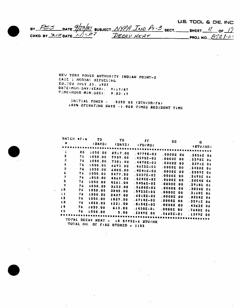
IrW YORK r'0Vrll AUTHORITY INDIAN POINT-3 CA:lt 'N-TrjflIA ' IlFrrU i.lG CO.''EV .JULY 23. 1907 D A 7r ( M UH ; rJAkY , i EAll) 9 ; / 8lB 7 TAM (HOUR -MIN: -EC): 9:3:17
'N TIAL POWEI - .535C 00 (DTU/ I/rA) 100% OPERATING DAYS ::1.000 Trinc' RESIDENT TIME
T)A1 III rI A
2 76 3 76 4 76 5 76
a 76 7 76 S 76
9 76 10 76 "-I 76 12 76 13 76
14 76 15 76
TO DAYS)
333333333.
1050 .00 1050. 00 1050 .00 1050 .00 1050 .00 1050. 00 1050 .00 1050.00 1050 .00 1050.00
1050 .00 1050 .00 1050 .00 1050 .00
.00 0.1399E 08 TTcrAL DECAY HEAT a 10.5792E46 8TU/HR • TOTAL nO. or rlAS STORED 1152
TS rr HiE (DAY) c(rDIPo)
3333 33 33l3 3 3 333 3 3 l 33 33
8517.00 7909 .00 7301 .00 6693 .00 6005.00 547 .00 4069.00
4261 .00 3653 .00
3045.00 2437 .00 1029 00
1221 .00
613.00
.4779E-02
42953-02
4470E-Ogz
4652C-02
4C41E:-02 503 71E-02
5242E-02
5456E-02
56801-02 5922-o2
6215-02 67141C-02 0154£-02
1430E-01 lider An
.0000 0
.0000E 0C
.0000V 0C
.0000E OC o000or 00
.0000c 00
.0000 00
.0000c 0
.0000c 00
.0000E o0
.0000c 00
.0000: 00 0000£ 00
0
(wTU / IR)
23535 63E 25561: 22901 23911: 24001: 25091: 26951: 2004:
29181: .30381E 31681:
.33241: 3591:
.43621:
2 2 8
U.S. TOOL & DIE. INC By DATE L Z SUB JECVW0-ZAT'0r SECT.-SHEET J~OFJ2.Z CHKD. BY ~/~DATE" / 16[ -~ 'PROJ. NO. 8~ -~
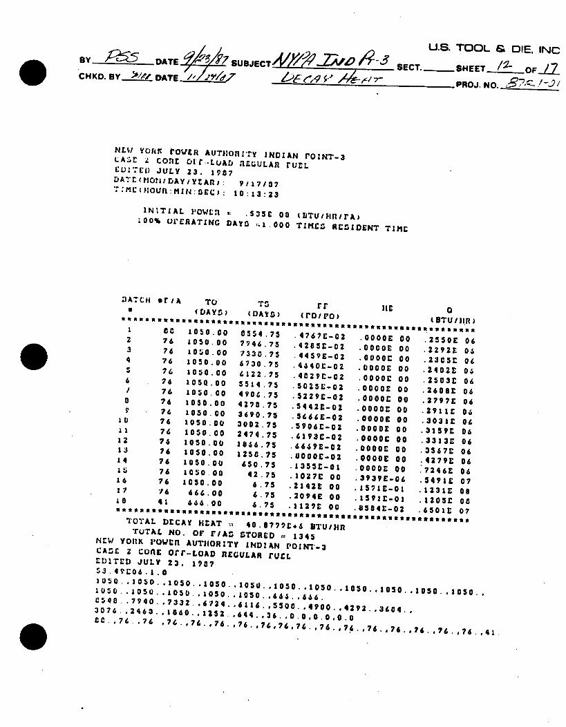
NEW YOhtK rOWER AUTHORITY INDIAN rOINT-3 LA O d Cofl Oir--LUAD 11EGULAR rUL -UL)7ED JULY 23. 1987 D ATr(flONrJAYIynA,): 9117/07 ":ME ("I OU : M1!: ,SEC): 10:13:23
INITIAL P'OWLl ,. .535C 08 (IjTU/HniFA) ;00% UrERATING DAYS -1.000 TIME.10, RESIDENT TIME
DATCH wriA
I a ct t lll 1 C0
2 76 3 76 4 76 5 76 6 76 / 76 0 76 9 76
10 76 11 76 12 76 13 76 14 76 15 76
.... 00.,a .10Z7E 00 .3939E-O .5491E 07 16 76 1050.00 6.75 .2142E 00 .15910-01 .1231E 08 17 76 666.00 6.75 2094E 00 .15910-01 .1205r 00 1e 41 666.00 6.75 .1129 00 .8504E-02 .6501L 07
TOTAL DECAY HEAT .. 40.67799,6 aTUiHn TUTAL NO. OF F/AS STORED - 1345 NEw YOjlK i'OWcn AUTIIORITY INDIAN 1OIN7--3
CASE 2 CORE OCI"-LOAD REGULAR rUCL EDITED JULY 23. 1907 $3.49r06.1.0 1050..1050..1050..1050..1050..1050..1050..1050..1050..1050.,1050.,
50-1.'050-.1050-1050.-1050-666-666. 0540- '7940..7332..6734..6116.,5500.,4900.,4292.,3604.,
3076.,24 6 3- 1 0 6 0 .,1 2 5 2 .,6 4 4 ..3 6 .,0.0,0.0.0.0 CC .76. .76 .76. ,76.o.76.,.76.,.76.76,76 . 76.,.76.°.76.,.76.,.76.,.76.,.76.,41.
TO (DAYr.)
1050. 00 1050. 00 1050 00 1050 .00 1050. 00
1050.00 1050. 00 1050 .00 1050. 00 1050.00 1050. 00 1050.00 1050 .00 1050.00
TG Fr
(aAm* ) ( P*D O)0554.75 7946 .75 7330 .75 6730 .75 6122 .75 5514 .75 4906 .75 4290 .75 3690.75 3002. 75 2474 .75 18.6 .75 1250 .75 650.75
.4767E-02
.4205r-02 4459£-02
4440E-02
4029-02 5025E-02
5229C-02
5442E-02
5666E-02 5906E-02
61930-02 6649E-02
80000-02 13 5 r- 0 1
11£ 0 (BTU/IIR)
OOOOE 0000E
0 0 0 0 E 0000E 0000£
00 00E 0000c .00000
0 00 0E
OOOOE
00000
O000E 0000E O0O0E
.25500 .2292L
23050 24020 .2503E
-2608E 2797E
-2911c
30310 3159C .3313E .3567c 4279E 7246E
U.S. TOOL & DIE. INC By ATE SUBJECT AA? SECT.-SHEET__ 1__F CHKD. BY 2AE__ IC'r /,r____ K. __DATE //_____/___ __________ PROJ NO. -7 - /-f
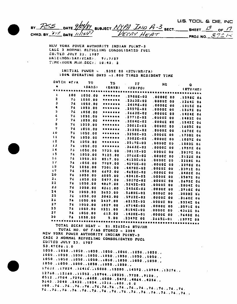
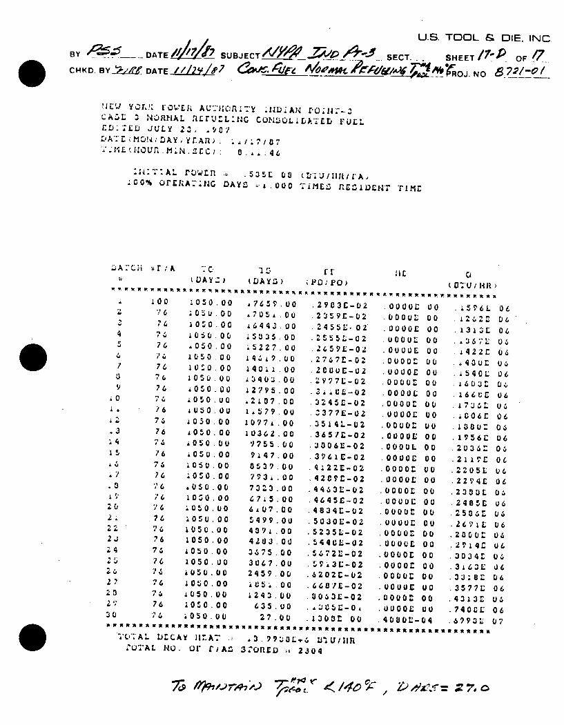
NLWJ YORK POWEtR AUTHORITY INDIAN PUINT-3 CALL 3 mortmAi. RLrULLING CONSOLIDA'ILD FULL ED.TED JULY 23. IV07 1-)Al t?1ONiIjAY/IlfltAfl): 91 7107 T'liC~tIOUR.iN:SEC).: 10:43: 2
INITIAL P'OWER .535E 00 (I)TUIHRiFA) 00 OPERATING DAYS -1.000 TIMES RCSIDENT TIME
DAICH er/A TO TS !'r HE (DAYS) (DAYS) (pD/PO)
1050.00 1050 .00
1050 .00 1050.00 1050 .00 1050 .00 1050. 00 1050.00 1050.00 1050 .00 1050 .00 1050 .0 1050 .00
1050 .00
1050.00
1050.00
1050. 00 1050 .00 1050 .00 1050.00 1050 .00 1050.00 1050.00 1050 .00 1050. 00 1050.00 1050.00 1050 .00 1050.00 1050.00
9 7 3 .0
9125.00 8517.00
7909.00
301 *300
6693.00 6005.00
5 ama0oN 55353N5
4869 .00 42 n .0 gammas.
N*3535a
''''Sam
533*555
mamasga
3733 .00 9125.00 8517.00
7109.00
7301 .00 6693.00
6005.00 5477.00
4867.00
4261 .0
3653.00
3045.0
2437.0
1829 .00 1221.00
613.00
23S .00 .179 0 .... .. vv 6oot-.. . YY 0
TOTAL DECAY HEAT i: 21.0263C+6 DTUIHR TOTAL NO. o F/AS STORED ,t 2304
NEW YORK POW,"n AUTHORITY INDIAN POINT-3 CASE 3 NORMAL REFUELING CONSOLIDATED FUEL I'D JULY 23. 1907
53.4 C06 .1.0 1050..1050. .1050.,1050. 1050. 1050 1050..1050.. 1050. .1050. .1050.1050. 1050. 1050. 1050. 1050., 1050..10.0..1050..1050. .1050. .1050. .1050. .1050.. 1050 .1050..1050..1050..1050..1050.. 17i6 2 .17024.,1641C.,S. COC.,15200.o 1 4592. 1 3 98 4., 13 76 ., 12768..12160.,11552.,10744. .10335..7728.,9120., 6512-.7904.,7276..6600l.,6080. ,5472..4864.,4256.,
3443..3040. .2432..1024..121 6 .,600.,0.0 zOO.-,76 .°76.-,76.,*76. .76,76 ,*76.,76.o*76.,*76 .o76. 76.,*76.,*76 .
7 ,6" 76 - .76 -,76.-,7.6.,.76. o*76.o*76.o*76 .o.76 . , 76. ,*76 . , 76. ,*76 .
.2900E-02
.2363E-02
.2459E-02
.2557E-02
.2663C-02
.277 1C-02
.2C84E-02 3001E-02 312 3E-02 3250C-02 3302E-02 .3519E-02 .3663C-02 3811£-02 3V66E-02 .4120E-02 4295C-02 4470C-02 4652C-02 404 1E-02 5037E-02 .5242C-02 545&E-02 5680E-02 5922C-02 .6215E-02 6714E-02 . 154E-02 1430E-01
.000C 000CC .0000E 0000E
000 0
0000
0000£
0000E
0 0 0 0cE
OOOLE 0000E
O000 D 0000E
0000£ .0000£
000 E 0 000 r
oGoo£
000 0E 0000c
0000£C
0000c
GOOj
O
(ETU/Hn)
.1598C 06
.1264L 06
.1315E 06
.1369r 06
.1424E 06
.1482L 06
.1542C 06
.1605E 06
.1670E 06
.1738L 06
.1009E 06
.1003E 06
.1959c 06
.2039C 06
.2122E 06
.2200£ 06
.2290E 06
.2391C 06
.2400C 06
.2589E 06
.2695C 06
.2004C 06
.291E 06
.3038C 16
.316CC 06
.3324E 06
.3591E 06
.4362L 06 •.7648E 06
U.S. TOOL & DIE. INC BYC .- DATE7 SUBJECT AyateW -ZiV 9 SECT. SHEETJ OF2 CHKD. BY *'1/7 DATE_____ -454 7- PROJ. NO. 67/C
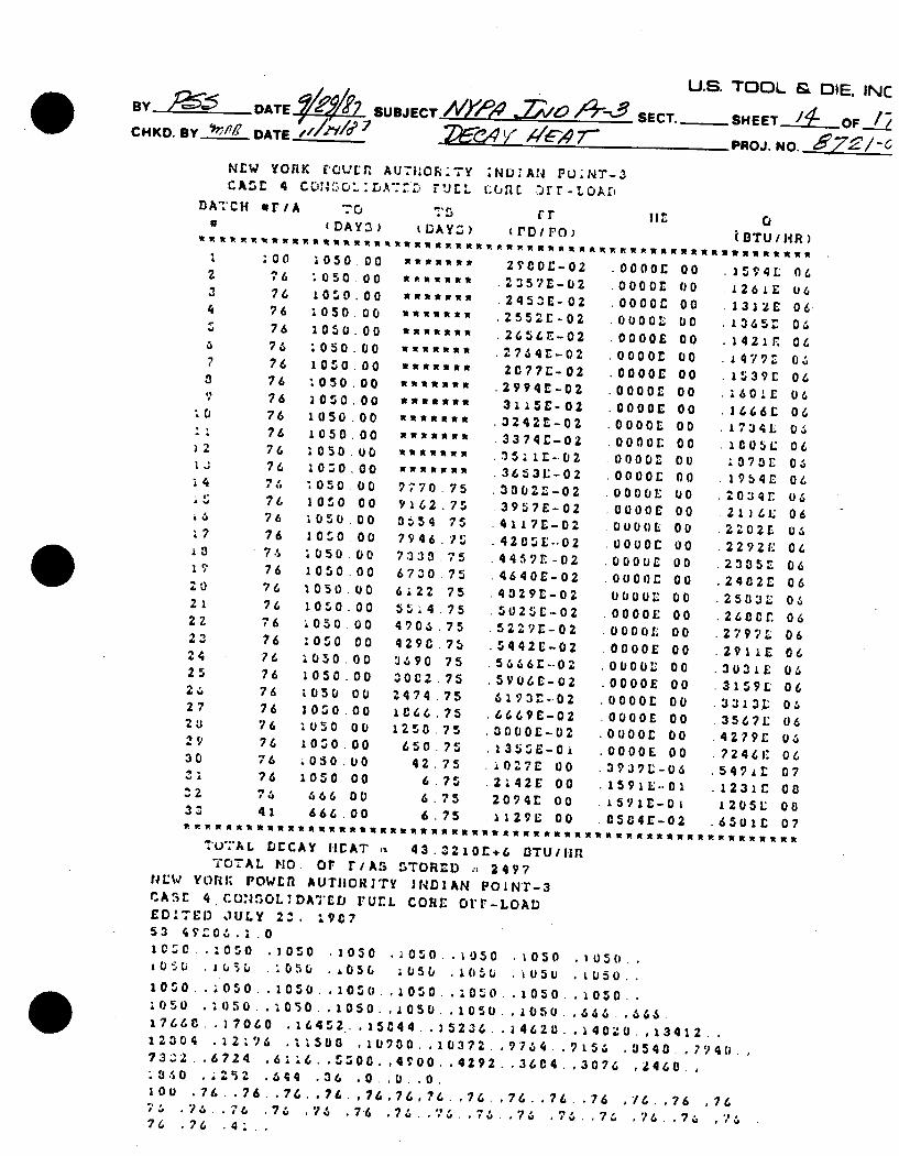
NEW YORK M"CAJ[f AU-I:Opi:Ty :ND:AN PU;NT-3 CASE 4cA-: rUEL GORE "JrT-LOAr,
DATCH erIA 70 1.,r,,,(DAY3) tDAYZ) cVDIPo) (BTU/HR)
2 7
4
,I.
A
.7
:0
2
22
4
2 13
2,6
19 20 21 22
23 24 25
'U
27 2'J 29
30
:2
33vvv - .OU [ L U(
AAAWARUWWWWWWRUWWXfWWWNWR WW AWUWAIRWsnarWN
TU7AL rJECAY I.IAT 43.3210E+6 DTUI.Ir 7OTAL HO. o riAS STORED :. 2497
U4EW YORK; POWER AUTHORITY 1NDIAN POiNr-3 CASE 4.CONSOLDATDij rUEL CORE OFr-LOAD EDITED JULY 2'. 19C7 53 4v$'06.:.0 IC4O . :050 .1050 .1050 .1050 .1050 .1050 .1050. i05 .1u L - 105u ,olS& .050 (0b •. .05 u USO. 1050. .050. .1050. .100..00. .:050. .100.050.os. :050 .050 .050. .1050. .050. .1050. .;050. 666. .666. 1766 .. i7060 .16452. .15C44..)5236. . 4620. . 40U. .13412.. 12304 .12i96 .;i500 .10700. .10372.9764. ,9.56 .3540.1940., 73Z2..6724 .6!!6..5'00.,4700..4292..3604.,3076
,24680 -3! 0 , .2 .644 .36 .0. .0 .0. Ou .76. .76. .76.,76 ,76,76,76.,76.,76. 76. .76 ,76.,76 ,76 100 .76 .476 76 ,76 .7.6 7 , 7 6 7 6 .?6 .76 .76 .6 ,76
76 .76 .4;:. .
:00
76 76 76
76
76 76
76
76 76 76 76 76
76 76
76 76
76 76 76
76
76 76 76 76 76 76
76 76 76 76
?U
41
1050 00 1050 00 1050 00 1050 00 1050. 00 :050 00 10s0 00 i050 00 1050 00 1050 00 1050 00 1050 00 10 z0 00 1050.00 Ioso 00 20 0 00 1040 00 1050 00 1050.00 1050 00 1050 00
050 00 :000 00 :050,00 1050 00 ;050 00 I0O0 o 2050 0 10z0 00 1050.00 .050 o0 166 0 0 666 00
WR a Waa
Wa RW *a W a aW a
A a WAR WR
9770 75 9162.75
3 1 54 75 7 94 6 7 .0
673 3 0 75
6! 22 75
4906.75 4 29 C .75 3690 75 3 0 02.75 2 47 4.75 1 C 66 75 1250.75
650 %5 42.75 6 . 75
675
29C0O-02 2357E-02
2453E- 02 25520-02
2656E-02 2764t-02 2C77E-02
2994r-02
3 1 5E-02 .3242E-02 .3374C-02 35 1E--02 3653V-02 3020-02 3957E-02 4117E-02 4285E..0
4457E-02 4640E-02
4329L-02
5025E-02 52291-02
5442C-02
56660-02 59060-02
6193"-.02 .6669E-02 .0 000£-02
1355E-0 .027E 00 .2i42E oo 2094r 00 ,1229C o00
.0000C 00
.000O 00
.0000C 00 0000L 00 .0000E 00 .00000 00
.00000 00 .00000 00 .00000 00 .0000£ 00 .0000L 00
00000 00 .0000E n0 0000E 00 .0000C 00
00000 00 .ou00 00 .000 00
.0000C 00 0 000041 00
.0000E 00 .0000 00 .0000E 00
.00000 00
.0000E 00
.0000L o0
.0000c 00
.0000L 00
.0000E 00 3937L-06 159 L..0i 15910-0i
15 94 L 1261E 1312E
.13650 142 1r 1 4793 1539C 16010 .26660 1734L
10730
20340 211612 2202L 22 92 c
2305Z .24020 25O331 2600'
27970
291:0 .303±0 31590
133 130
35670, .42790
72460
.12310 4 S205 9
06 06 06, 06
06 06
06
06 06 06 06 06 06 06 06 U6
06 06 06 06 06 06
06
06 06 06 06
06 06 07
00 08
U.S. TOOL & DIE. INC.
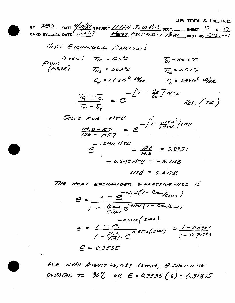
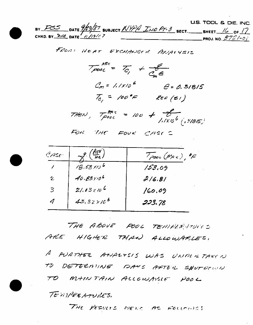
BY C5.. -DATE 7 SUBJECT &/YA1 , -,3 SECT.-SHEET /-- OF..,-, CHKD.BY.....zLLW DATE /au7 A,4f r 6 r-f.4 11-,4,4 e. PROJ. NO.____
7,"= /. ,'C.
AOX.6 7 o,,-
-7,-'@r: 7-4)
.. C-- IM-d-/
- , 2/4~ dV7j~/
-
'= a. .,44-4 r 4-;=x Cre-'74. Ae C? / tCA /r 5
- 0,5/721 (/2)
0- .7"f9
e= 0.3.5"2-
P6 e IV W' Aec&vr - , f -F /7
ZD&79J'0 710
I&rr .0e hi f
7c-
.A v " r7 (As-(4x )
'y /4
.9h-l ., -7,ovr,,l7--.7Aez C I
= 4, a f-/
0 /Z (f = 0 Ar.6.5' 6 9 ) r , , S/ 8 1-r
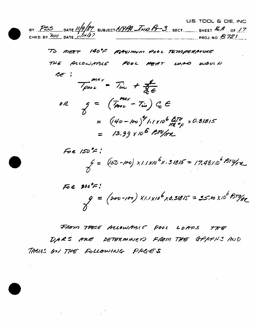
U.S. TOOL & DIE. INC. BY A DATE_ _ SUBJECT M;.'I 7 -3 SECT. SHEET /16 OFIZ7
CHKD.BY 5'/'e DATE//i' 7 #Z,__ ____PROJ. NO._________
7e;:' o /; I A L- 4 7- L' .d. lt/Jd . , .. ArWS/"
/
/oc A: ~ee;c (~,)
4 4~-~-O ~~}/9A~1
,26?~e~ /A26~ /;;y9-i-- ~? ~ ~4,T-,2?. / .j I,.-,
:7.-v /~'2~#,A.-~~ 7W,,t.~' ,4c L C; ~&4~i r
?"~ -;
I've,..- ~'9'~. eZ.~L~~~n.): S
I
Sle -
.
,-41e~7
7 __ "wr=
77,e ilrou /Poo-, 4
U.S. TOOL & DIE. INC.
BY BY DATE. /, SUBJECTPRSTH N /7
C HKD. BY____e DATE / ,4__ _______-PROJ. NO. 6 2
0=
Z67-, WOg o4
r-v oe .
1,t/--~p
WL.
A 3. y v~4
X.Jh/fv
lftv,71~r t4z*W,1eh5 r Roo t- Lp o9-ip-s %
44&( 07- 776 Ao4 0IAe P~1iA) d 715-t-4S'!,~
eV2,ft,, moo-" f0tv 0 e
ooPoto e- Ajew 7- 4,opl*-oo outoLve 4
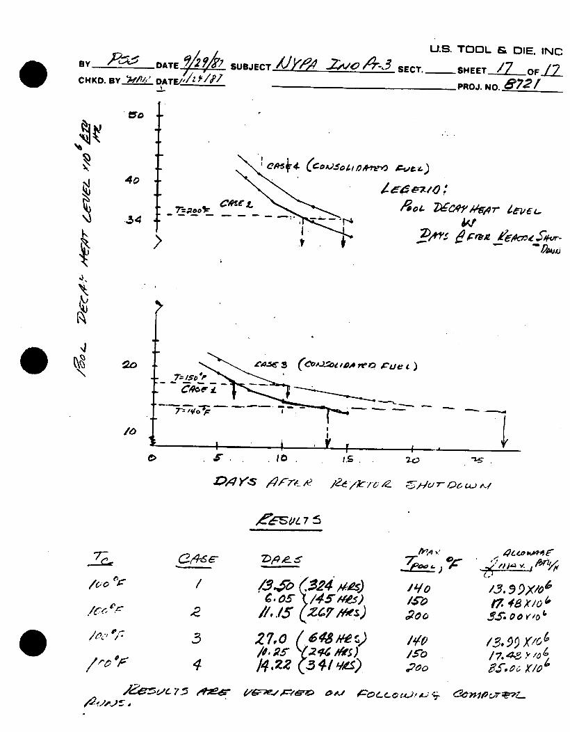
U.S. TOOL & DIE. INC BY DATE______ SUBJECT XI* P-OJ409 SECT. SHEET 7OFZ CHKD. 11Y 2W&4' DAT/'/Z;'O'/" ____________PROJ. NO. 6721
t
7's;oo~ CdftdL ' od. C4eYA' - -5
.4IC4~* S
7"-/o'P
....... ....
V 'V I V -LI.S.
Z)4YS sro.: ,' ;WV7- c.e6 C,-) ,./
,eC6SO/ 75
i~.1-5 (24 #&e)
//../5 2(47 hs)
2-7,0 /27 p /4 . 2
14'o 1A0
/11o
'.3. 9 9X/olp
p ~.9 X/61
75 ,#~ I
6'~~ 1~t~7~'~ ~ #'~i g5LL 0 £4).' ~n 1v~2~?L.
/0
I0
-
/n-., 01-
6 48 h te ',,) Y2f4 h*' ) (3 4 / q&),
U.S. TOOL & DIE, INC BY d . SUBJECT .. ... C ... SHEET/ 7 4 oF/! 7
CHKD. BY__ DATE P~J2 7Ld/47~ 4 ROJ. NO. 0~/o
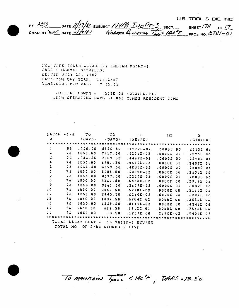
L,*!C, W.K AtC:VEA A:'ilCI'ii :ND:AW PO:N'-3
£EU;[ JtLY 2,3. 19C'? 'AU,:i tL'yAd, 1) c
" : ' ~.: :' U l. DAY : Y . Afl. !l ,&'3 4.
:A1. "O,.Wr.l .535r 08 Li".J/IIuu/rA; :C" % OiER4A7:NC DAYL :1.1 .000 TLIM3 RC .Dr.R'CN "1';ML
L1A DY Z) DAYL, VD f D/ PD) t ftr u / ma )
i050. OC .00 ti .00c n
1050.00 10 .00 1050 00
t05 0 00
1050 00 i u 50 00 i10 .00 1050 00 1050 .00
8525.50
7917 .50 7309. 0 6701 50 6093.5U 5 05 .50
4C77.50 4 7 .50
366: .S0 3U53 .50 2445 50
1337 50
1229 . 0
621 .50 %d 50
4777E-02
*2"3Z -02 4467E-02
.4 L C -- 02
5021r-02
..5239E-02 54?E-02 56flE-O2
5910Z-02
6704 4'. -- 0 2
* 14it2-O!
.1737C 00
.00u0c 00
.0000CS 00
.0000L 00 00 0 00 .oooor01 00 .00o0C 00 .000L 00 .0o00L 00 .0u00c 00
Ooorf 00 .U 00 00
.0000C 00
2 17CE- 02
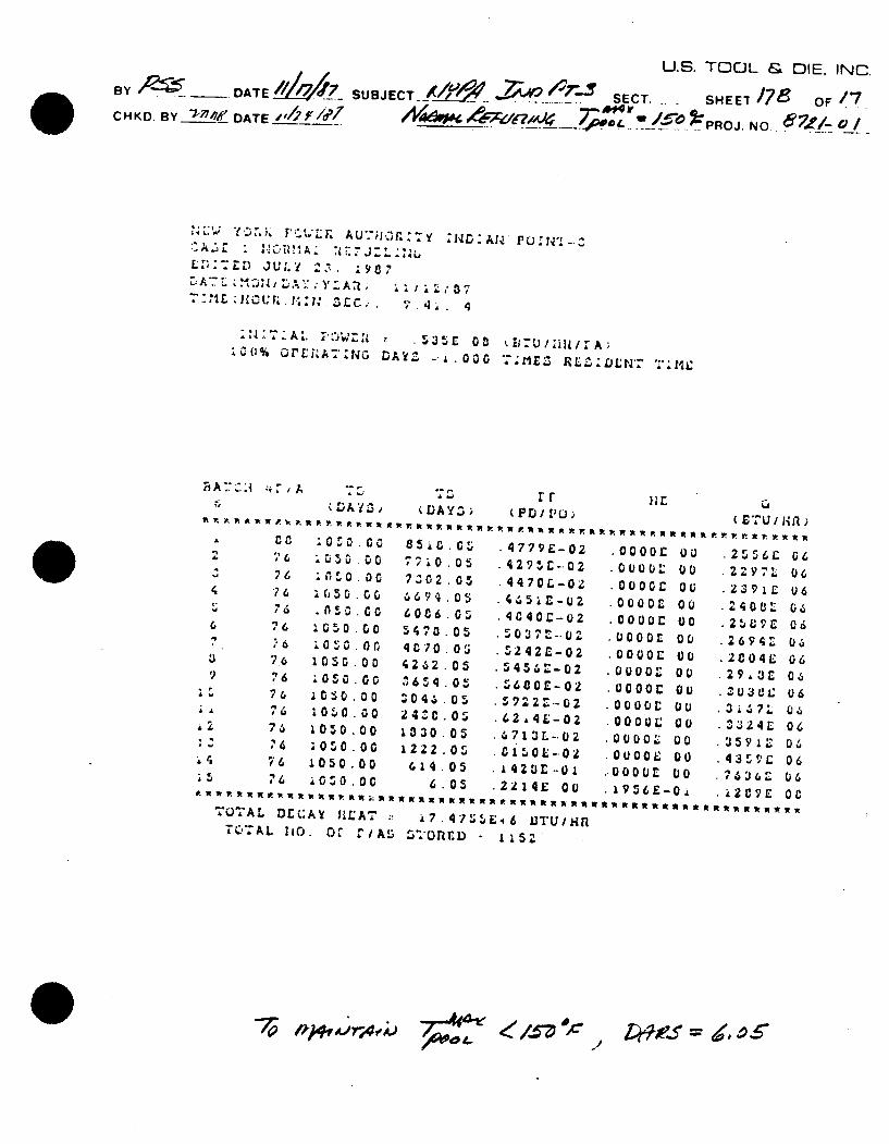
TU7AL DECAY JEAT ,. 1.98012E.6 DTU/Hfl 7OTAL N. or "/AS STOanD :. !152
AM ( 0
2555 2296Z
2390E
2 9 1 7 L. 3037C
358 Z 434JL 75531 94 0C
U.S. TOOL & DIE, INC. By ~__ DATE A46 4 SUB JECT- /(,141 Z;' SECT. -SHEET /786 OF /7 C H K D. BYr' DATE U '-.. r7 PROJ. NO. 8&
Y ; LK A U-;j 'r y NO zDAN P vor' .
L. .J U 7 2
2CIN . A : "' tD t :. ., 035.E 0 - U .]R A
' 6
2 "'6
476
62 7,
35 76
iDAY3
1 0 00
0 0 0
0 00
1050 00
0 50 00 10 0 00
1050 00 1 e000
TOTAL Dr(:A¥ fIZ'AT *i74253 E.6 UTLJ'UIIn ,TAL laO. OV t/A .SO~ - 1152
-~ fk*A/~~ ~Z~9f ~.
(DAYZ>
7710 05 7Z02.05 6694 .05 60c6 0 S470 05 4070 05 4262 05
6 54 05 Z046 05 240.0O3
1030 05 1222 O
614 05 6 05
rP r R c
t ( A R /' 1* f ) t .4779E-02 4 29 5r-02 4470L-02
4040Z-02
42 42 -02
34362-02 3680E-02
62 4E-02 56713L-.02
.C1SO&-.oz .142o-..0 i
2 2 4E 00
.00000 o0
.0000 00
.000or 00 .0000E O0 .0000c 00 .0000L 00
00000 00
0000: 00 .0000L Do .0000C 00
O00O 00 .00000 D0 0000 00
.2556C 06
2ZY7L 06
.2694: 06 2C04it 06 .29,U£ 06
.303el.: 06
2 4 E 06
.3591 04
.43 ',L 06 .7;'s3 4"' 06
U By ____ DATE/ ? SUBJECTVY0W 14-- 9. SECT.CHKD. By _ DATE .. '4 '~~// c.~ co
.S. TOOL & DIE. INC.
SHEET 7C -. OF /_
PROJ. NO. e -
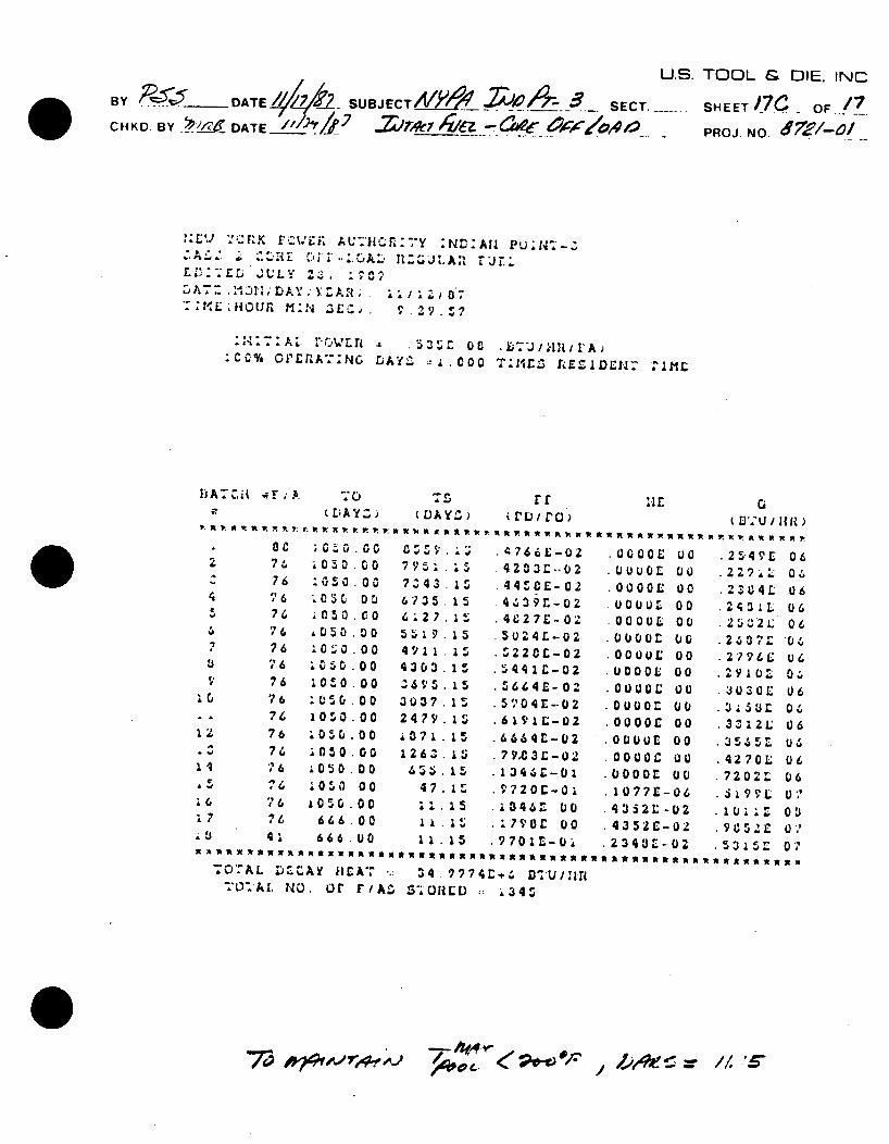
,.7~ ".:3 j'3U ij ; A t"r .1CJ '¥ 7y ND :A U PtJ: 4 -3
L (' Efl J U L. 23. . 9. AT. LDA , . V' A R 1 r . .L l107
-0H O 1'R M , *4 z Ll .n N -Y*' I.C O
'.7 : A1. l"3'L u - 5 35 fit ,T'J/41111I'A C% OVER{A7ING LAYL ::!-COO T:11ES nrE lIl-- 2IML
11AT Zit ; F,;A -1, UT5 LDA Y Z ~DAYZ,
rr PrL)iro)
G
.030.00
a e' 00 0 5 c.00 050 .0
0 50 .00 ~0o .1a00
.oo00 1 00 0
400 .00 1050 .00
1050 00
iOSO .00 i 0 10 O00 0 rl 0 00
666 00 666 00
C7 5$..
7343.15 7V75 .5 75 Z 43
4". 1.5
4303.15 3695.15
3037.1 2479 i5
1263 13 263 Z5
47.15
1i5
x1.15 * m7 w a x * w w~.L TOAL DZCAY /IA .. 34 .9774r.L D+UjIr
. NO. 0r or/A S7-OILD ;: 34S
4766E-02 4203-02 44C E- 02 4439r-oz
*4C27E-02 5024L-02
S220L-02
5 44 lic- 0 S 6 6 4E-02 504E-02
6664L-02 79.C3L-02
13 46C-0 9 72 0 E- 0
.13046Z 00
.17VOC 00 9?7O01 L- U
0000E 00 UUUDL oO
.0000E 00 UOOUZ 0 OCOOUL 00 O00OUL O0
.00005: 00
.OOOOL 00
.00o0C o
.OuOiio 00
.0000c 00
.000UL 00 .0000C 00 .00005 00
10771-06 4352"-02
4352C-02
/*0~ /
25.49E
240±5
.2 4 3 9 2796E
O030E
3312I
4270L 72025 279 L
A,9 1 u
73 'o blrv. --- = //. 's-
U.S. TOOL & DIE, INC 13Y_?5 /174k ____ '7-P<
Y- - SECT.- SHEET. OF ...
CHKO. 13Yo,. DATE_//2r/4'7ROJ. N 0.6
' i.-' YCZFL' [OVLJ.E ALh7_ : fL~Nro~:. C"ALL 3 NOR AL ,rrUL-L:tlG C '"LiLA' L F'ULL ED:'ZL JULY 23. .907/ 'A':'E MON,'DAY,.'Y r.All) . ,07
& L "i.ZOU .C . 0. . 46
:0:"71 AL ruw, .D .535L 00 .'-MZl rziar ;co% o£rA_.;fNG DAYS L-i.000 T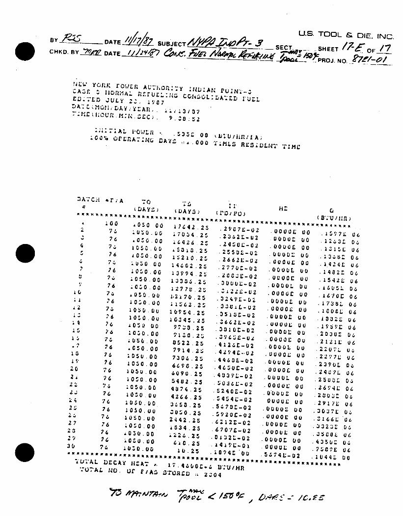
U.S. TOOL & DIE. INC. BY A SECT. ---... SHEET !7 -EOF 17 CHKO. BYW2~ DATE Pn' ,R' _ 6Z 4 !&XPROJ. NO_
NEW' YCKK rr./LJF A1'.:ORx.Y zc .28: IAUN £DEDr JULY 2Za
"T'.M:£ :U .H N , 9. Za 5 2
:;a~~~gIAL0 Ikb;" . $ S= O U/I /fA; "100% OrEPL'R-;1,G DA L ;:A.O000 T MLS; RL:i VJZT "'
4 :00
- 76 474
76
76
74 76
74
11 76 13 4-q 76
76
76 13 76 2$5 76
20 76 23 74
2,.; 76 21 76 -. 76,
27 76 23 7 29 7 30 2
AR RRRUR
• 00 O0
40Z0 00
.00
10so.00 .050 u0
~0 :0 .00
.0 0 Uc .00 .00 1 030 00 1050.00 1050 Ou
50 .00
10,j0.00 1050 .00
05s0 .00 105 0.00
.OO00
1040 00 1050 .00 10 0. Ou ;0 5 00 10f0 00 1050 00 1050.00 .050 .00
• 050.00 jOSO .0
I'U7AL DCECAY 1IA 7. 14,5(05' 707AL 140. L)L r/As 5sruarDi 2.;
'DAYG3
7? 42 25 7034 25
',426 25 4 5 8 A8 .25
,5313.25 1402.25 13994 2
1277 25
1-2! 70 25 11562 25 10954 .25
970 .25
7 1 Z'020 L 0522 25 7914 2 730. 25 6698.25 4090 25 5402 25 4u7 4 25 4266 25 3450 25 10"O 25
2442.25
034 25 60 .25
U .25 .
(I'DPo
27705-02
2VC7-02
300 0 1-0 2 245O-02
.4 29 45-*0 & .2662-02
52050 02
592or-02
62124-02
0± 02-02
S4 y 9 -0 2
4212 L- 02
.4443L-02
.520-02
a4707C-Oz
1074'00
04
.0000L 00
00006c 00 .0000L 00
.00O0L: 00
O0OUOL O0 OOOor 00
OOOOL 00 .0vOOO 00 .0000L DU
.0000C 00 .0000: 00 .0000j1 00 .0000 oU .0000c o0
.0000L Ou .OOOOL o0
.0000L o0 .0001: 00 000O: 00
.00001 ou OOOO. 00
.00001: 00
Oooo 00
.0000L O0
.OUOO U0 000 00 .0000L 00 .5474L 02
704
-
C, (2.u1"1
V 73L
15 Lj
1 4
73L
2 1224
2 a 9 Z o 2207 j.L 22771: .2390:
.267.4( .28035 C
3037 0
.21I66L *0 3323: 0
J:a E 0 1.450: u
06
06 06 06 06 06 06 06 06 06 06 06
06
06 06
06
16 6
)6
U
6
3A-:C.*i 4r;A
U.S. TOOL & DIE, INC
BY -DATE # SUBJECT,/VYP4 -A'/- _-3 SECT.-SHEET / OF_. CHKD. BY 2,41". DATE/,,L. As,' .- ,- PROJ. NO. 6 7 /-o
q4- 6t 7Z/- e
_ l e ." . ..I2: I /EA Tj'4- A"-"/ I2 //A rZ. _ .'- I
7; 'e t 77a4-- Pdi /,S r- )A
.. Z-A ' 7/14 7- 0 A-5/- . -/e-/1 5 K
/ I 4 -rPh5 l 7 / /YZ .o z S. A- "
A'/.. ..C '
/,57 . 'Z~
o74 .374:.
__5o 5712M___
U.S. TOOL & DIE, INC 13Y F DATE~Z.. SUBJECT_________________ SECT.-..SHEET ?- OF___CHKD.1 *Al DATE_ t'oo6 PROJ. NO.________
/7"4; A,/7 . ,4 /, 4cc ' /., -e -
/-A11L- 7 -.. ? ,$p ,0 47A
2o le 4. /)0 Z- 4, 0_
Z ,,'6. 1W/ . 1.
c::'!0-I o--V o4 7 "we,- /A7w/e /
96C)
ICeW6C 7';7/ 1
=143.o ,,15 -.6
'OF - rc
By DATE SUBJECT_____________
CHKD. BY..)r 114( DATE____
U.S. TOOL & DIE. INC.
SECT.-SHEET 3 OF -'2
PROJ. NO. '7L'I-oz-
- 7A 4 e-d'~4.~L /AJ e--E 7-/A
(Grl )P& I(c F -- .D-,"9 77- /6 0 37
,;:o z e 1
) .4 =
~C~#C ~ '2 ~C?~')~I/t ~
_0"q/ A-, .'/
- ./ 7x/) *
F1,e ew i-c dy -7,'4 .Z7y
,?oO -:1O = 0-42 7A //7.9- /dC11.9 0 g.
ka~me_400 Z"' Oc
VZ/e (f- e,.5",.5-,3 PrO' ' q
r 3 , " , , U ,vr 4r *?c
5" 5-3 x
/c , .z. I 2J ,.' ?-,,-n d - f ,. - . , . , 4 "-- E- .,- _/0 rA~2
T,4'~ Po/%~~v~ I
6Kf / ,4 -77-1 A-)
-~
77.06c- Oc:-zler e--
T 7'A( /2_L
U.S. TOOL & oIE. INC. B3Y -ATE SUBJECT A/V' -- -' SECT. SHEET 4 OF_ CHKD. BY *//. DATE i___2___,I___7 _PR oJ. NO. 'Z
Z, .~~~) Af4 3
AS- 7. . ( .J#r/v - D 1V7,-,4eC - -7/">-t= Cq" €.
t~j4,c --o 89254 .4 9 .
~ /z20 -7Jc
U.S. TOOL & DIE, INC. By ' DATE SUBJECT_ SECT.-SHEET , -OF. 2
CHKD. BY ;.-17 DATE __ _ ___7_ PRO J. NO _7 ____
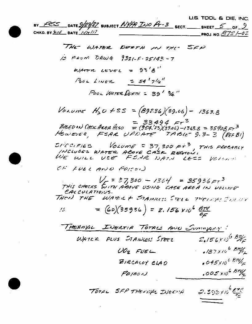
.. Poit>.. T724W, - 39" 3 ,o ) ,4",
= Cy 2 J ?.oR-/J. - .7Y/7
A/ e/5
"-/' ,P;# $A.r.e- ,e ,, 45 -/ -/4-.9. =j, 55 , 7 ,4ptgj /~i~4 4-~ 4e4 U S---k
v 7
;r/ I , _ 30 0 -- AF, o 3 x0
P-lt-L PLUS ,7A,)Wf 1.5 6X1 /j,
"0 .. , /o "
U.S. TOOL & OIE. INC. By -DATE SUBJECT /0045V 2 -0 SECT.-SHEET. 6 OF..' CHKD. BY .24_ DATE "/,h _ __ PROJ. NO._______
- 7-- -" &- Oo4 7- d,_ ,y00-o
o'a-- To
6-! 77A-v ae-= tv, _1 6 t-C o10 .
SLA7)I ;~-= A3 C
44D Y14
17 .4 o 7,3
12
4f5,
"06- 117" Z
~2c~oF -
BY-DATE 9/*?/48/'SUJECT AIY*'/1 ..7A/0 *4-*5 ,/ D CHKO. BY A'AdL DATE I,/hy/P
U.S. TOOL & DIE. INC.
SECT.-SHEET 7 OF 9
PROJ. NO. _7._-
-c (2_ - /o, o) %X9g4 '
= ,Ap. J
,4.fr. 4 D
* /0. 6 X/x6-rse'
7
/4"-
CAe,.- 3
ee'fnz 46~Me
-- / - M L
7Z) 42 19CW
,219To
U.S. TOOL & DIE, INC.
BY _W SUBJE -T _._.SECT. SHEET _ - ..OF 9-. CHKD. BY 'AR DATE______ P7OJ. NO. "_ _O-4.5NO
Pc'os~ -&- V&~ 4-. ~ ~?
______ -~ ,4~f
/7, 4t Yo
-7Z-~o
e,. / /
. So
0.£1
1,04 f- . . .
Ce 0 e
sp.oe 6 / .
A°
I J - I -
/5422. /4A01z
/%ozg
('p
153 9 **'
,1,& xio
J. ,o s l
6'e::&e
4
^04.
A0
14o /5"0
'1
(?4~.
/
Es
09..
xo or 200 *F
1,0 ie
c~ (~
7'. 7
.50 / I- - og"'t
7F
U.S. TOOL & DIE, INC.
BY '-_ DATE 7 SUBJECT NY!. 4, -. SECT . SHEET 9 -_ OF CHKD. BY ' DATE If 7/' PR 0J. NO...-71 R N2-
/,7? 4e-o-pt) AJcr 17t-r~ e .CS= 0/-- : 7-'CI&l ,/,6
4 .Sc~)mz~A7z~ ~ 7-,~'?~C ______- -
-,o'
/39X14
'104 elo I4
-4
7,3o
7, R 0
o.o /9849
g/4\
1 1 4
-~e3
o.BZ
/0,6
57.4 74.9
-7.4 74.9
A, ofJtLa
wattclf
V 6'4- f- 'Ar
At l -
0/,~c~L 6 o ,?cc~
.~ (004 f74i2 ff~'~9ce~' /? i') /61~ PT/4
/
/9~~~
14o
/50
o3/
"43
c o--)
.,?',4 7r- 1 'L..
h
/. 1 7 1 ?1//, 11; -
lfNel -
= Ptq cz-
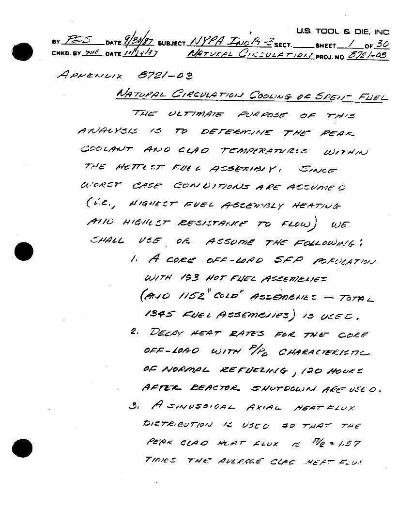
~~ U.s. TOOL & oIE, INC. By.=±L DATE SUBJECT -7'6 -4 / SECT. SHEET / OF 3c CHKD. BY DATE U4~~O/PROJ. NO.____
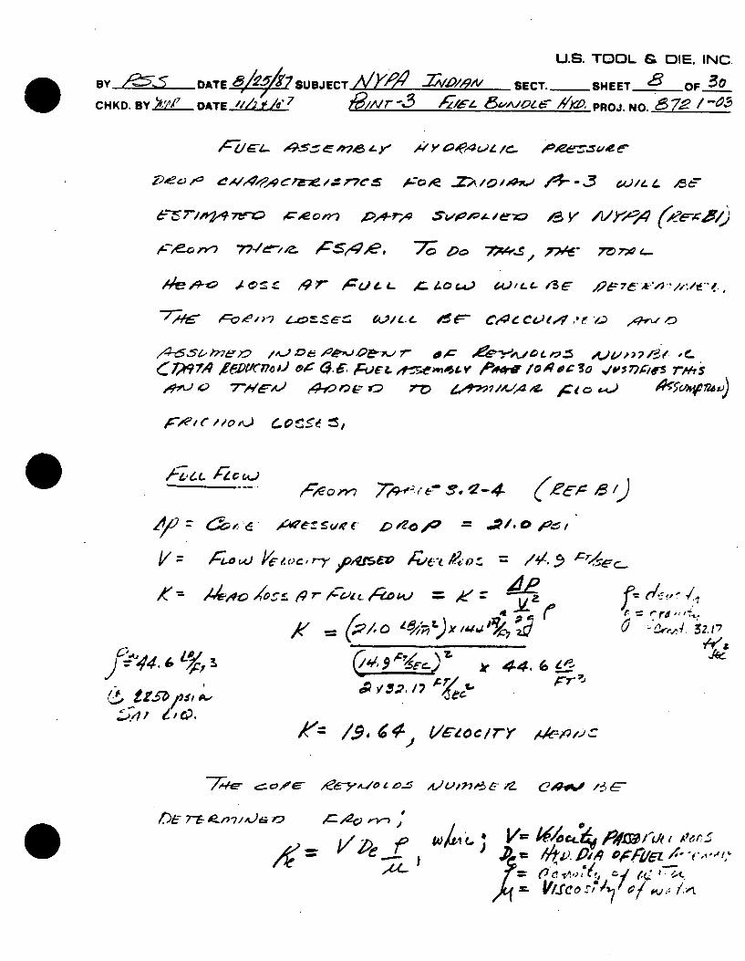
=7-?./ -- ~~~7 1-. &"-L:z a / ,o.- c 7" _
,,$/ 74,7./ C' iEC4 ,7,Y/ A,/,e- C'c., x'. o,_c
e- ~ 7/0 774 4 gp'~E~oc ~
L ~4-~ 7 ~ 6C 4. C' r-47,2(r;'1 77//1Z d', ee , 7
7716- o4c, 77-e- r 7 '
6lle. c",,t7" t " / . ,, 0 - - ""
A14c~e'~~ -e0V0 424 /' Z,0070
OPC r2V4~ 0A0, 77 e4 rx7;E/t- 77 C,
A,., rZ JP 64C7o-.5 oU74
U.S. TOOL & DIE. INC
BY I-" DATE SUBJECT SECT. -SHEET OF 3o CHKD. BY ','117.fDATE ,I/____7 PROJ. NO. Z--" f
4L;W- 7'7,z6 ~ 4C7~'/ 7'C S 9 cOg -/ /
~ c~?7IC4 /0.oc & ' 72A: 2/.s'
%-~ 2 ~ / , 9E z' 7i-e ,,, . 7''/-Ef..' ~7
A,1
IC ,.;.c ;,W- .o ( Z/ - - ,r"-,,
~972s /J / c / 4 ¢ L'" C 7? 9,A' / 'O-' -'K ,' , . "
7111 A aa6;A1 77 5 oVV7- /1./f- j
ej7,#FO.-OS W.--S 75/'//-/ IMr 77-5 -- K
&17?7'4w~ KA'ee) / ~A36- A-*~ 2~ 'A)7~g7
U.S. TOOL & DIE, INC BY /~S DATE ,e/~ SUBJECT -YAX9 4 2AWAc'Pr3 SECT.-SHEET 'OF10 CHKD. BY 2__' DATE
PROJ. NO.________
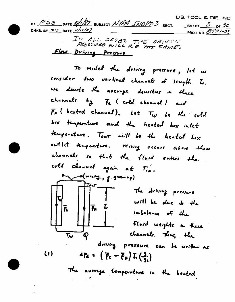
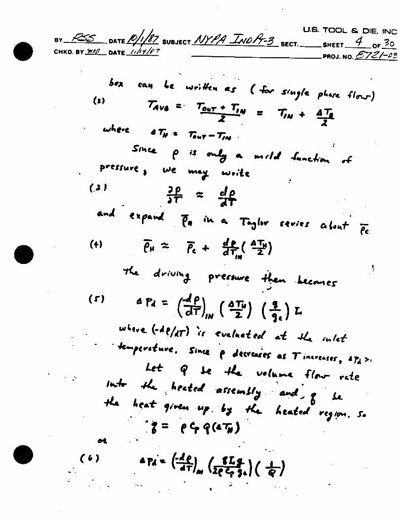
_F-l D-iv,'. s , 'p.e,
Tro mocdS ,. jvgv*11A e~ae
k c Le.ed CIA.,..S) Let! 7T, .j co
Lr J 44s. 4cad jr, jk
To 4r wollI le 44, Acafgf S., O~4 I* 4 .sf4Ai"re l c.: 44rrC41eve 4
W;IL 44~ a A- 44L
Le w t t) Li it,
4.
tott
pret~sIv, CA". L4 3e4,A
9I) •r, (?e-
7 L 44.
U.S. TOOL & DIE. INC By -DATE __ , SUBJECT /V)/ SECT.- SHEET 4 OF CHKD. BY *119 DATE /,/ /j'7 PROJ. NO.________
(
Cou as~. 7;~ = 47;,
rA re- -IS ~e e qe.d 4..- i, e,
prerrur W Le id4 DUt
'.31A rE
Cya..d ~~~g l,~ T&Iv kif (.-
I
fJecr6e ats Td ?A'er >T Le*~ qp Us 44 (k 8-%4 i(I.q e
Itdy .4 Sog *14 ~ ~ c V era) , S ~4. eie C/~.
(l)
.)
& U"L
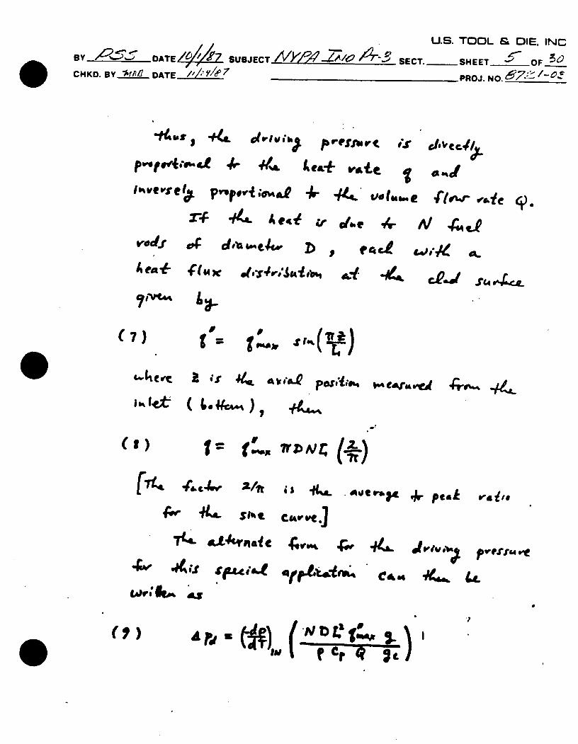
U.S. TOOL & DIE. INC BY , .- DATE SUBJECT IV /TA .LA/& T''-V SECT. SHEET '_OF CHKD. BY ._1/ DATE ___ ___ _7 _PROJ. NO. 97 ' -/-O-- 7
*t~sii41 44L ub 4 rex+ as(i'
lveve;; Prro'vP -- 444 .' vo4,.e
x-* 44& A e- zr coe -4-
vdf *,~b. e D
7e & '= "erv~db
ewveie j)
li 4,4
t~lvf
16% 1t
a..~ .~
(a) 1= as 4'- F.4., 24
-- '141
~t Ab~A.Q ~OSeiihs C4Jfu vea 40ub 44,
(S)is -& 1 . *em
CMv.IC.)
4VOK fp 4L
4. Peal v.,!,e
Jiu .0 pvr14A
ur 4e ("N, (LD c IV ?atc~ 1"(I)
U.S. TOOL & DIE. INC BY... . -.DATE V4 SUBJECT /, r -S-SECT.OSHEET OF-CHKD.U *-Y___ DATE____ _______________PROJ. N.__________
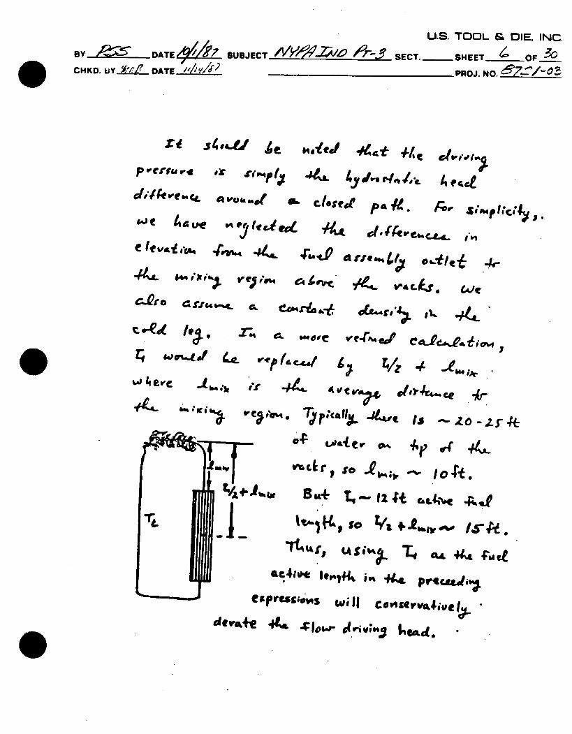
XE ,o .,,UL/ , .ded ./ttr i,/c .. ,.,i 74 4_ sitI , 44. /... A~s' d4# teer 4V~ k or t c .4 4s r4 o *4 c. 9 -Si pk. ,
"rdat ks ., we ,4. cc
W- ts r s 9% II c osoiue
eIfv. .*o 44hiih 44 .. -ri,.-; i .4 4. iil £jeem VJeA C4vc i4, 4.~
C.Qro eamr h~e a(Agk 44c
#(- ejc4. TjpocaIIX -#,, Is s4
as fter, so to io 4 t.
4+-v~t I, U+T,
ac1t gc4,.e~ . pvrtcmatl e;~rss.~qswell CoeSavvejt
U.S. TOOL & DIE. INC.
BY -~7 DATE4. SUBJECT A/'4"i'/ -6SECT.-SHEET O 0F 0 CHKD. B1Y .'M/- DATE /,/_ _"_ PROJ. NO.________
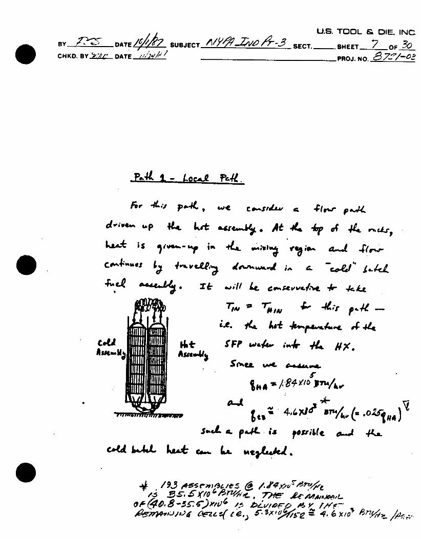
-P.., IL-- LocA- r,..
L-P 44 tot ogb~ At 44 4r of 41-t ma-. LoA+ ;~s 4.P.WS ~
A4 IgJ4D * 7 , =I L , t.-~ t . * r- 4 x
i..e. .4 4 4,
,~1~C~i'4' i~uL L1 mFF w& ,. ,,4r i'.
Joe. ca L . ,,t . ,.,. ,.
4 ,,/9%.345
5-, 4. 6 ny
U.S. TOOL & OIE. INC.
BY D -D°ATE /SU3JECT /y .Z/A,,,9A, SECT.-SHEET OF
CHKD. BY OiZ DATE /1/29 7 I'/Ltr-, t/'6 & ,oUE- //y.6. PROJ. NO. 7i /-'
P~--*- 7/0~ e7L.- 9, o.AZ-) .97 or-: O/d 7/~ ('As
(4-5.5t~'b7-0 2,/ ") o /e".. AP/* 7P /_'4 'y- / Vtk ,'
~~~~o o,) 77A/-A- 7704-c' 7V' 7;d e-I-7AA
40 - ?U 4 L. C 4 4..- & -, ,,
4_zr _ e - Ce/ Co ee ., e,. /4 q. 'D; , A4_=
K ~ g~ ~ 2.17
Pk 44.6t.
of ~,t 7/ OQ/-"A wRiL; oc4 -,n.1
A4 V'/e k'* 't
BY BDATE___ _7
CHKD. By .'/-'/2 DATE_____
U.S. TOOL & DIE. INC.
SUBJECT 421e ' SECT. -SHEET 9 OF A
"Ce4 -, I 7~A eo -
Z/c A7/;0 e ~4 c
46-#IA-5Wl A-7crL t
- / 3k- A0 e e !A,t
- r'
AJe~7~j A~,1
A.Ue_772-o /1/e-;wmv -
A~e~7-0 -= Fffg ,c-
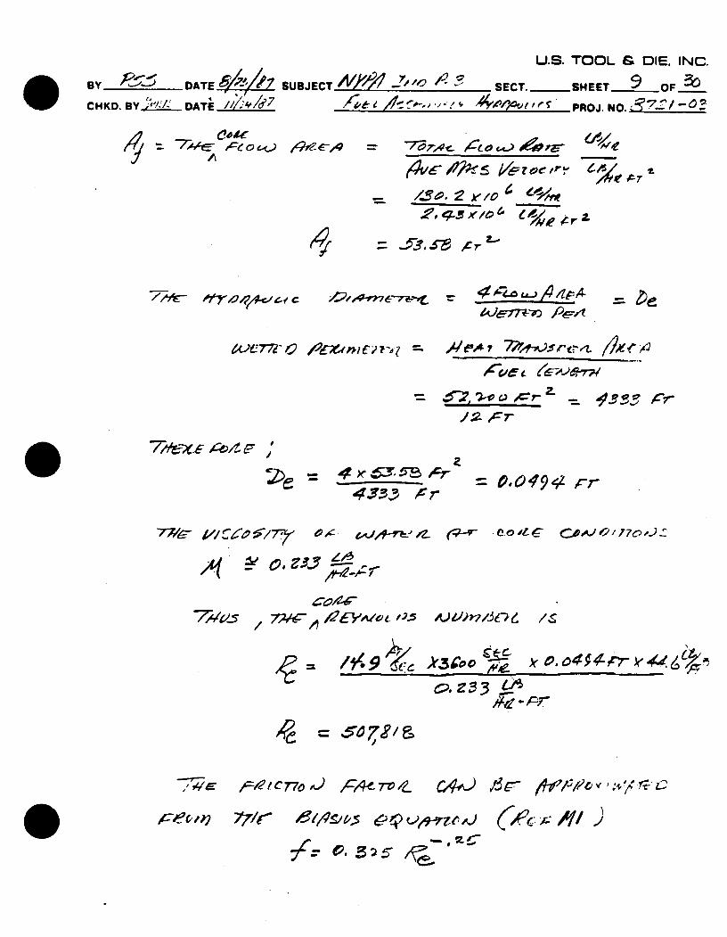
7/,+--x. ,¢,,1 r ;,
4-5 A7 433 cr
O.0O094-Z rr
77/45 'p &47?49~- ~~ CV"'?
/ia_ "5 46ZV/~C6
.9.~
= 50r72,/ &
7WC oe-121C 770&) A4~C7V IL
771r c.lV 5 I
C,4-ej 13C.- / P / -cy',I, ".7-t-c
U.S. TOOL & DIE. INC.
BY ,DATE SUBJECT 4,,!!2 -Zaw 4 - SECT.- SHEET /0 OF CHKD. BY____e DATE___ //C1bh /Y0'41,,( PROJ. NO. ~ 2-i
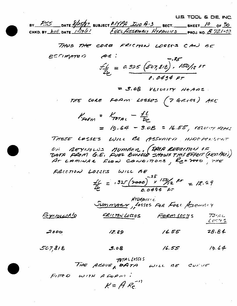
/9 -- 4 - = . -/-- -. s- tf)e e-.5 eCc',~4r
4-e- o9 M mo, - C4 4) Cd' -0 7 7Z" 4:= ,.- -~g
FZ~c27-r 6).rei Y.u-. o46 - f
_______ It /V~rt-5 /-Vi orpf_(. /047f- 7/..'r
el c
L1
,F1 ife C
/0.,bl'-
cc/., t167-,A,) / Z- L 13 6,
U.S. TOOL & OIE. INC.
BY DATEL- - ' SUBJECT 404'3 SECT. .. SET
CHKD. BY Afflri DATE:Y1j J~icl 4 L5 __ afX"Ilt--4X-PROJ. NO. __
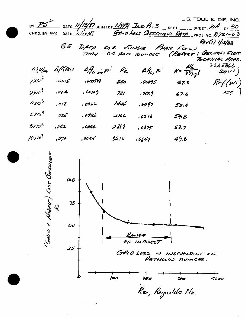
0,ol4 cv 2/ o , .' o'. .
x/o3 .0/ Po D- .21 . ,o 6,.6
I X/0 ,, gp~r .0 1,02-4 SI0 3,,
&X/03 *04z 0044 8 1 o3 7!* 57
i 4l
75.
5~. Mxe 7'
#4 T-./o4o.% v,,,#t,.
I I I I,
/0o
ee~~ /~5,s/4 A4
U.S. TOOL & DIE. INC
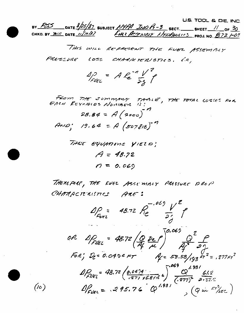
BY -DATE____1 SUBJECTAW -A&0/79-3 SECT.-SHEET O CHKD. BY ,." DATE ,___,_ I , ,, -' /Yri,,, PROJ. NO. 872 /".?
e' 77 .
-, 7,4- flJ-74c eosfe--72;; F->1-
)/, 64 =-4 0
r,? = . 0 6 5
/
457Z
oCe /;;
- ; 0, 7-V 2
A"- , C? '._
= .¢., 7 / 9
72Yr- "er-
6?4 ,4 C 7? -t I f r7 e-_X
AeJl Z
rve,
7z Wi-
)A 92:410,oltwn
41,C-941,rL
7
U.S. TOO
By DATE,,. SUBJECT 1 ' -Z1', --3 SECT. ,SHEET
CHKD. 1BY____ DATE_____ __ _ PROJ.
L & DIE. INC. -/ OF_
NO. 7 /-OE
,- . /"-0 el4A- c z- Le-
(i
/I V 7,,,Z4
1-- " -- - *I #" # r
T,,, c- e -=_ , £O x /t P-
S'o772'/r P7 -- 6e Z/_L_
7-qot ,C,;', CLZ .
,,o"5 C,) r (.)19-Lo 6 -k ' / r ,-
'. = 2 c,'e. /2
),
74-t-A odc -
*.47'1)
~*~2
2 = 0. 06 72: 7,
~/e /
)
-7-/4- 77 7*Lr P0e~d~ i~£~ 4~~z r--'~7ol"-~24
I 73/ 4-./7,7~T~L
(ii)
/ /L .. ,Di,) .,<7- 0,C" A " T .. ,,,
77/c 174oze P14177e7,--,'e 16 4'1
- -W-5.76
(11J4 P 7' rV le4e /C )
Norg-'f 1r..X W /,&
OX 771tr BaAIVZ407 0
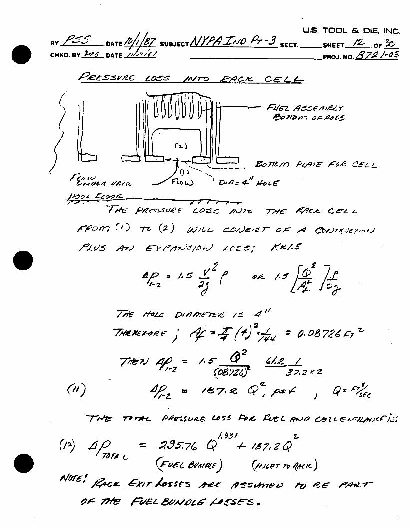
U.S. TOOL & DIE. INC BY eYBH,) DATE SUBJECT,/Y Z/000 SECT.-SHEET OF___/CHKD. BY Idz DATE _____________________POJ. NO. ~7 -:.
5" 4" A L( ftL P4#ire / ri
44""k - & 4w-.lx-a
oo#e/co& ) O 4es A u
of~'~s er Mwe- = ~,z ~~9? ="Zs$ -o~* &dh J
bh*~4E*jb4 <1,. (n)
ce4, 444
47 (/97g2, 1
f if-.. B7, c .
44 o. . p ~.t ad wye
CO41&..4 of
ey h,,'i.Fv%. VJ C
"Pve4ewi-
W1. 7-1, =. a-Or
or i4ameq-V. £',4.
k L cob...gev vb,,.#(p .L.~.44)
W4) a d
P is 44
'MeToJ
. h
Afow- "P
w,'1I f/ L
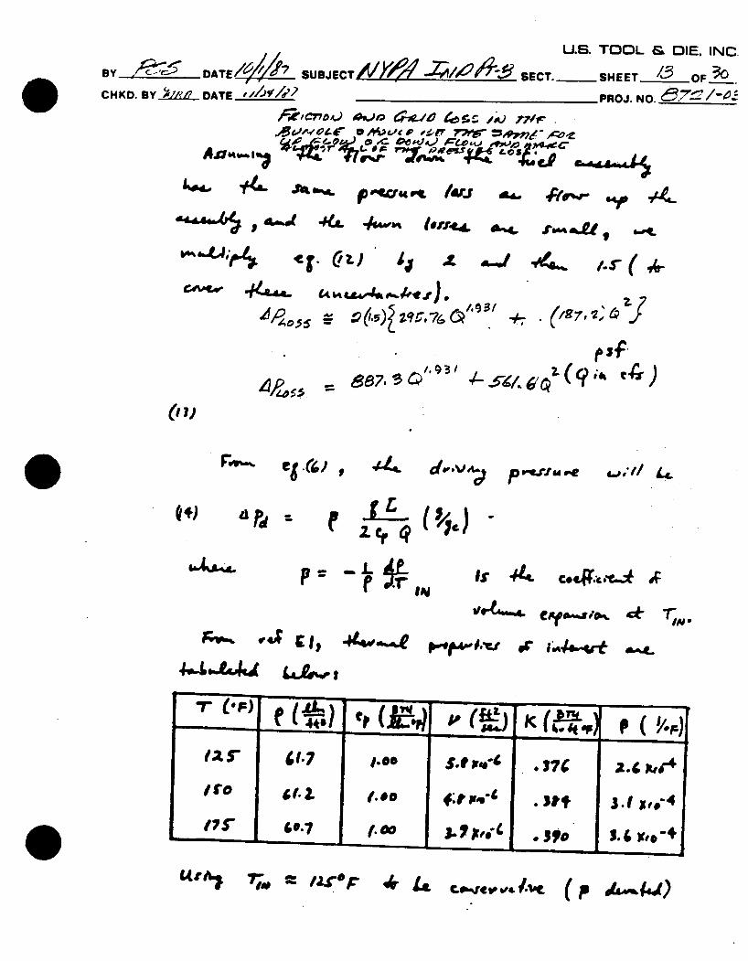
BY B I DATE /6 SUBJECT.
CHKD. BY 162WI DATE____
U.S. TOOL & DIE. INC.
Yf,,-, , -- _ SECT. -SHEET -OF
PROJ. NO. 172-
co'4ce-zz Poc
#M'7~.' )oc~ e6~ 9,4e~- ~-t-'e, y C.; s e/. .~~r~'7:~/ ~ ~ f: /-7119779-~ X~l-'e4
0 .- OC..4z I (, .4eaZ,,q1.770~4.1.
/, XA /a 4:*' f,/V 7- t, XereY 0
4 PZA:-_.-Y / ,
(93~-j ~)
7/--_ 2 7- __
0 e 7 - z a
,d.&I -I-
/ ~' eCtr. )~4
- A ~ ~-~
Ye-
Ae = //504
/f
cet f, 'u/ /
co 194 -o , /
f -
= , t, i - , i/77 .'-r if ? or7 Y -1*6/L o
4,8 g -r e
" A- 77 V ,Z 7. , t , - ly.4 4?
ow A &-nre'er
P 6, 5pe '7o
Pe
( 7&-Ie & u e r A-, r
_ C'. otfT2
U.S. TOOL & 01E. INC. C.BY ______ ATIa,% _________
-- SUBJECT__ _ _ _ __ SECT. -___ SHEETOF CHKD.BY ~Rl' DATEJ,/'Y . _ _ _ _ PROJ. NO.________
- e. L-'9..0 60_ 7,7-- rv e, .C c/77 Ja- 4 -<, =,-zz ,,A/ o ,
= . 6 10: -
3, rA,41V'. ' / 2 A -, c l -4'
c 1 ~z ~C7~
-76.
"C'
1/ o-Zo-"d; Zge-c
A 24'1 7 ',eF, XV
z -/.d eI / (Z,:3 ,' P ) = -0 7-./ 8 Q i:
/le.-
U.S. TOOL & DIE. INC.
BY _ _ DATE SUBJECT________ _1_ _ _ SECT. .... SHEET 2_OF_3o
CHKD. BY DVvl DATE /____ _PROJ. NO. A7"'? / -- 5
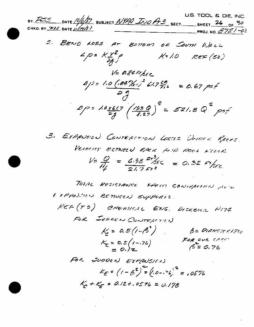
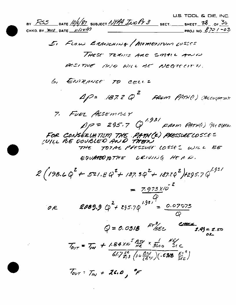
77t'C'!.% ,4-op S- ont-f e- r
7Z~ ceL~ ~
/87? 4*,P
/:Z' 2 7 CosJ%&Z* r1SM ;/7h 2t6
7W~77A5- 60 -- ~~4/~-('~
1 , --1 -2 , g 4 ) z 7
zz95- 7 q
= 4 o O/4
- 0.07973
.f4$ = 9. 5-
/ 36o o Se c~.
te7
70.r,- 71v + zeo °F l
~'C/fLL
4 z 2 (/98.4 C?
Ad I,,.) g f- //He ;pp m7w-v^-7
,oo e e o -- " er 7 -e - o. ,
e , 1! 5: ; -;,e-,,i ev c r- -
*5i =
q/.93/ , , Pk,,.,l) < ),
7 9 73 ly/o
.q/.p:
U.S.
BY DATE /ala-J- SU BJECT " / 'i#_ ,,-. SECT.._ _
CHKD. BY _t__ DATE________ F
TOOL & DIE, INC.
HEET_ OF 30
,ROJ. NO. T /)-3
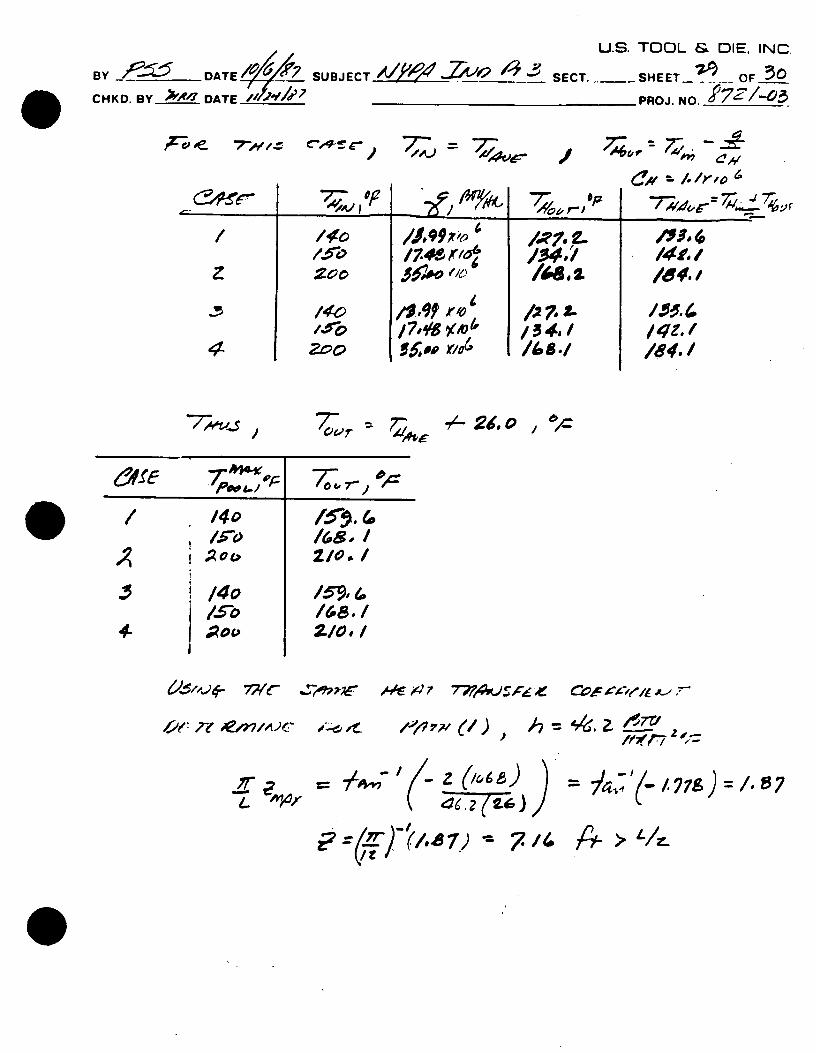
7-~,o// C4-Sr ' 7-
I I -
/ 740 r'ad
1:,9?,o 4
/ 7# 18 )(toor
-- 24 o
7o-,7-' 0
/Cos, /0, /
/59k 4 2.10. /
#4 F,47 7W.4i)_'iocee
,,'~ :.,_
= 7L4 ,
I (_
)
Z, (- 6J, 462f6
7f- > /-
, ,_
/
2c'o
-5/W. Z. / 4/
/4.1
/4vz. / 184.1
ap. l. 14eog.
1 9/11
140
/,o 14o /vo
95' 7-7 ,4An,.Cos'c~c 'elAz -- '7-
ff~w~f72 "~=
74V"C--7.7 , C I AG 7'
7 - 77
= ja-&-f '(- / 7 79 ) = /, 13 7ff ' ' .e- , '41
Z7 (7T) (AJ7.)
U.S. TOOL & DIE, INC.
BY _DATE4C//_,Z_ SUBJECT /,,Z/. ,- SECT.___SHEET3_0F 3 0
CHKD. BY ____, DATE_____ _PROJ. NO._______
z', ; / 7')
7-., ?-,/ I. /.5"
A.e .,o142,1 184.1
/,tz ./ /84,/
, f vU
A2f. 9
/so, 9 izz. 9
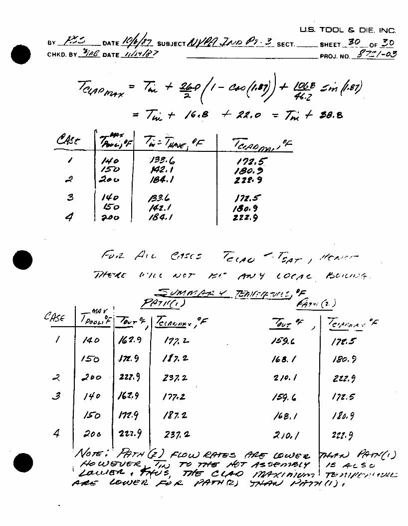
/17V V e 0 e,4 e-
4~- _ ____ 'P ________ 47;.. (?~)
/ 2
.17. 9 /17..
'",9
17? 9
2%2.9
177,Z
237.a
coe/ ve-?) 7-0 77'6Ar 9 4/e-, -- L ~ '-e- S c,
/
414V
~.
/Ho
-- ,,o
2/, /zzz, 9 171,.6
/,
/Il. 9/N,, /
-d4st I
77 4 44- q-p /4:74447/af x
Z
/0 It 8 -1/- XAf, 0
/17f."
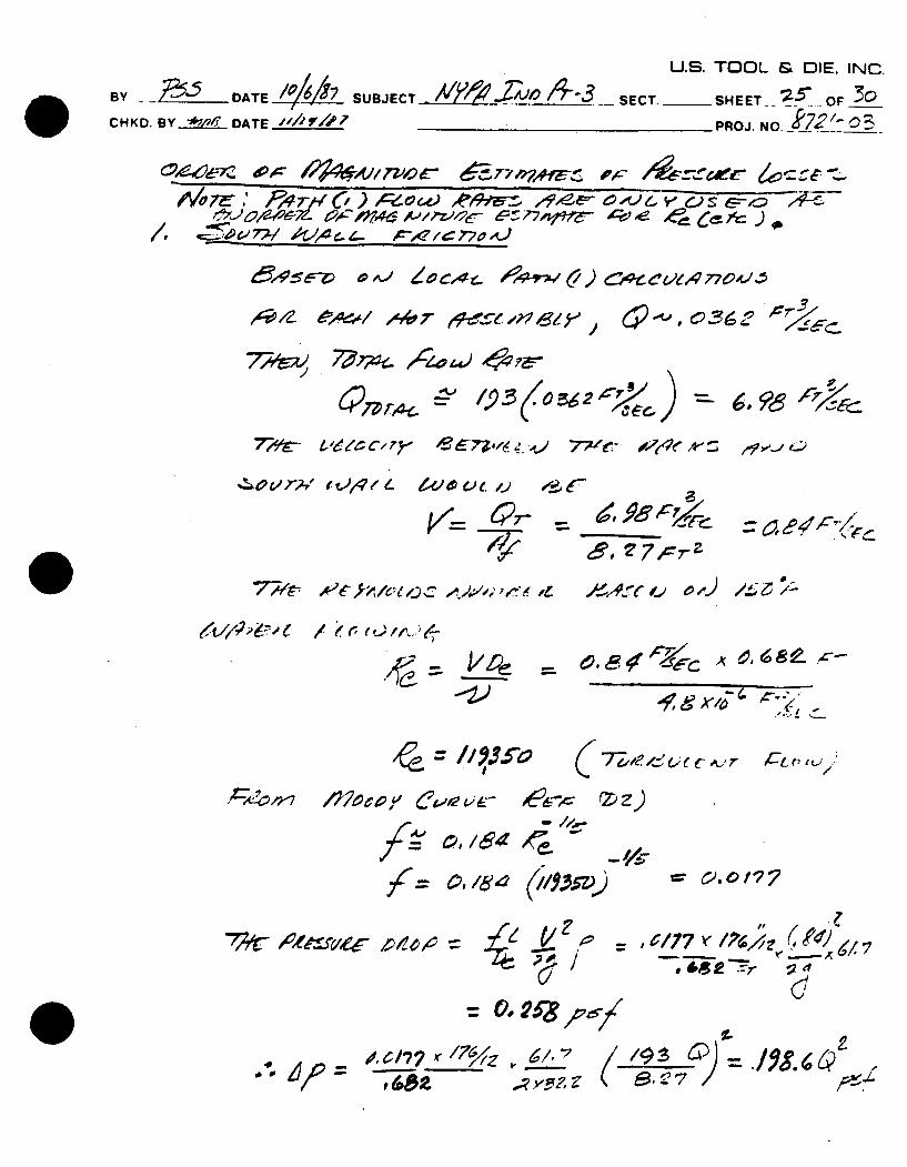
U.S. TOOL & DIE. INC. 13Y DATE I /# 7 7 __ - SE0 OF _ _
CHKD. BY t AW ' DATE _,/,/,, -__PROJ. NO._ __- 4
oc •v~p 7
/ / ,:5 - -,/ 0 9,-,
,4/-z y A~mc, ,,, ,o, eS . 'P v £-- A-z '-/ .7-.. A E 7-)
7V oqlwe, J .%1AVj /7lc 41Z-S'4
77' 1907- IZ CeX.? _ X 177 .2. 4M7
'& b ~ . '- ' t 7-- 40 t La ? 3~ A ~ a
4'CV5" *Lo Vs ~ 7,,' AI 'r-'pc. JeO'r-" '
jrrhh*"l",0 / '.5 Wc/77/ IAJ #'- 4'Ot ) &X £'V-1e5C ,dCo;,7
7-"~ A c' / , 4.0 0 -- ' - A,47
,,,',, " 7,,/? - 57,,-.,e,, -r ., . ,, " P "'-.../412- e
U.S. TOOL & [DIE, INC. BY -___ DATE SUBJECTN _-:/:;,,o SECT. SHEET OF CHKD. BY__ DATE PROJ. NO._____ 4
. e'.- " $ -g. 1L , ,0 7,,- €-,,,tb,,4 5p4 .- -e/,*
4 *,' -r- , 0.
,4 ~ ~ t , pf 4 - . * 0
-7Cw$t~ -T5// Z 06f7W± 'a%'l
oloir
QA7
/' , - ~1A.,v~o4 -O77"o-,1 , 4r', A-- -,/4 - A-,-1 .4
i -"°" ' '7) -. 7 74, ,
U.S. TOOL & DIE. INC.
By DATE SUBJECT -061W14 _Z____- SET SHEET 4__ OF __
CHKD. BY */? DATE _ __ ___ __ PROJ. NO. _ -44
-----. 0 7 .
- ", -- e - ' , 0# t' e , ,- k
., -.t ,, e '1 " ,' 'c , - , e-". ,, 7V o IoA-;p ,,
~. .j ~r
/e', ,j,, ,,_. O4.4.. , f = 28.->!/,vr) /* ,,! ,.
U.S. TOOL & DIE. INC.
BY.e DATE 2 SUBJECT 1 K 20 X,.1Y047-? SECT. -S5EE 2UOF/' CHKD. BY DATE______ _ _ /_ PROJ. NO.-Z7/-
R 'o, / (F- o , ois )
10 7 -&W &W
41L?~&t~'A' WOAIuJA L
I -J
I. ~ I
IIhf IIII
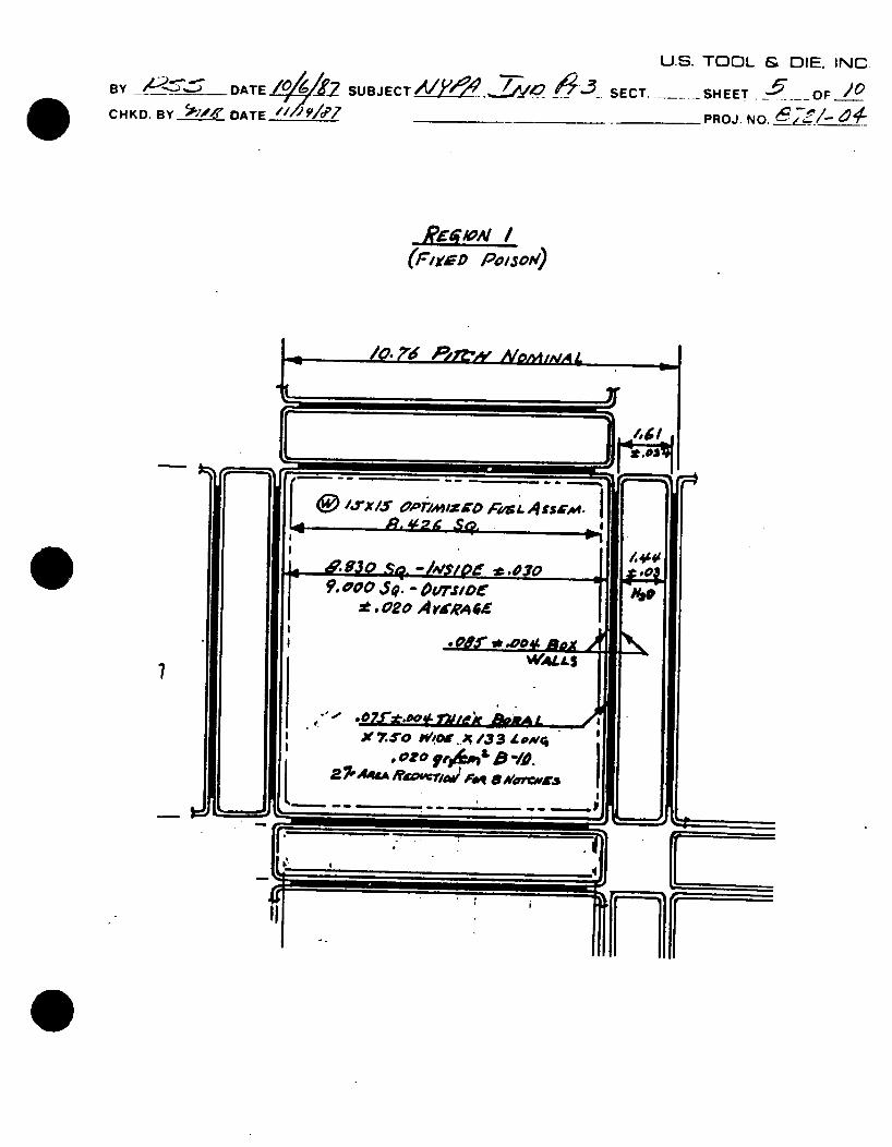
/.rx s a' orxh/-,v' p A.,& 1. Ass cm
~53a s~. -A'so~ ~.D7O 9. ~oa $Q - O~'r.roeI-
0. 00 ,5'. - 0ou'rs..o t .02o A varRA4
-0.!I * .004 A&M
7,'A.'" ,,$eO &0 /, X .5o ww...,,i /3 3 L owq c
2 7AAt raomriw I 40% aroves
(I,'
-1
461 Hl
± 0.
'.4"' A V 41
,J ~:i I~~=======
fl
I
L
Jm
Ilml
U.
BY__ SUJC SECT-'~ U BY - ___ DATEi-- SUBJ T_---SECT. _
CHKD. BY ___ DATE 19/""7
S. TOOL & DIE. INC.
SHEET OF /O
-PROJ. NO. ~7'
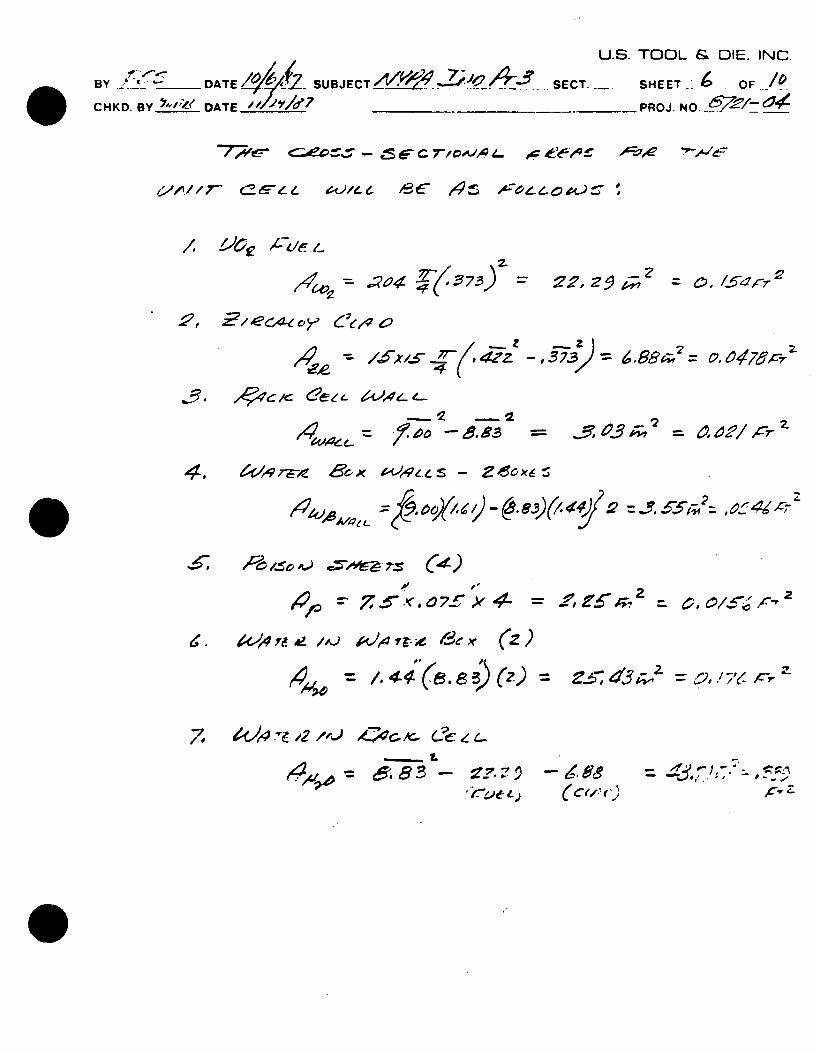
=*7;v5- <eo%.. - .5 o A,, 4- a te r
141,ja 4 4(/57-3) z 2r, 2"1 ; 2 = c, 154r 22
2, ~/ec4-1 ~ ~ y Cc,.4o
'4 ee
14Ie ..c- 03 0 a = o 2/rz-1/00
4. 4',qr-,l Sexl&4ef
- f, O/, ( -- -) /,4 2 = ,?, x5T4 2z, ~bl-;141,eAOOZL
" s v 4- =" .
,.4.j(z
7, A4,4 -e 12/,.j A. ¢__, C... c'4..I.
- ~ eI -Ve& )
¢ 88 = d,,'T ;:::,
0.6-,
C4e e
/ M9or
= 4.9 r- 7 = 0, e479-'S-73
,6, lo gclc (?&ee- z 0,4e--'
(
// U.S. TOOL & DIE. INC. BYD- BY eu, SJECT SECT--. SHEET 7 OF /o HKO 'Y"DoA'rE ///4'/p/
-PROJ. NO. __ __/-_-_
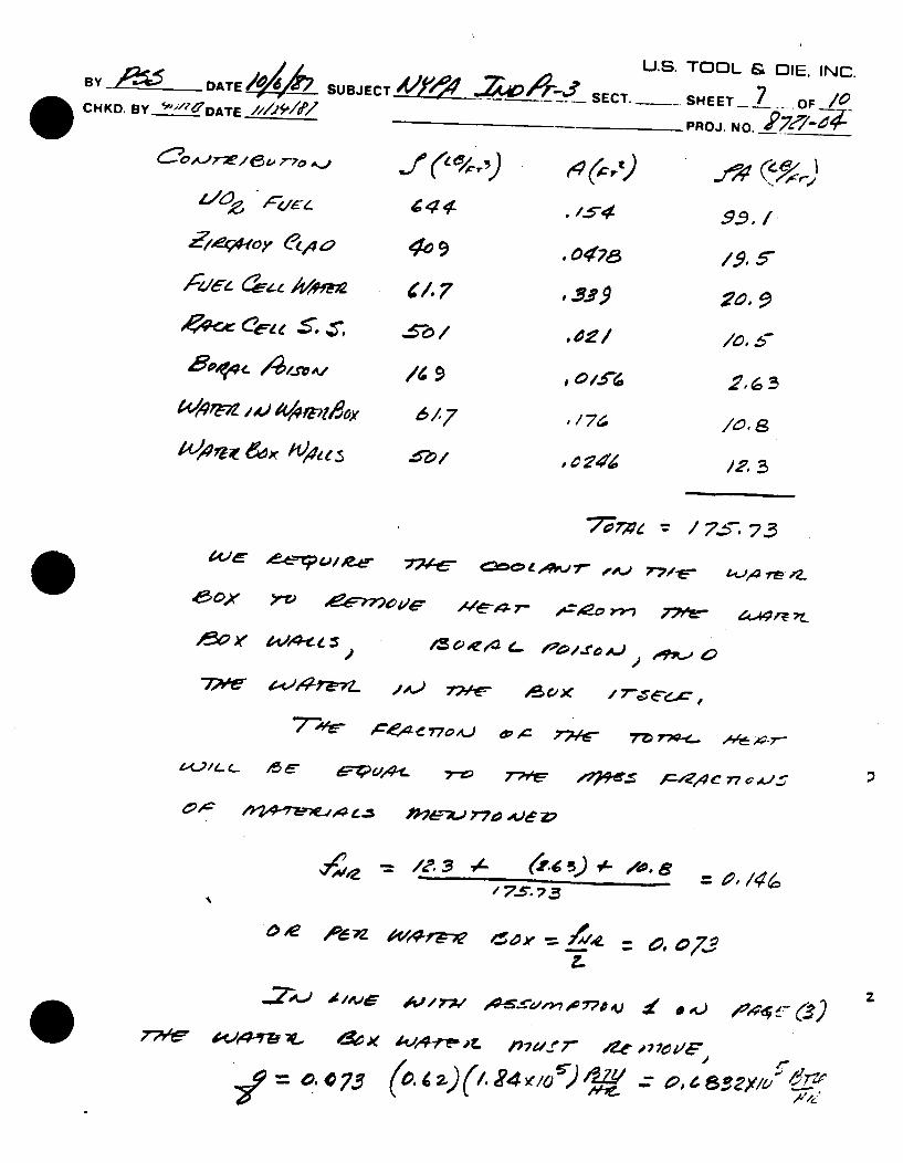
en,\. 7-" -9 r
4.1.
WPM .4.)o AAoP,6 617 / 7 .5 we*~fr eo,4
A ? , AD
"7-, -4-t- o 00 ^?ar "&e -s:- £- i"
/ ')5 73z0,
.d /, d~ 4 / ~ ) *1 *~ ) / ( "
U.S. TOOL & DIE. INC.
BY.~DATE 1W4 SUBJECT Ak$M .ZZ . 40 SECT. -___SHEET OF O CHKD. BY- DATE ,,,1 _PROJ. NO. _
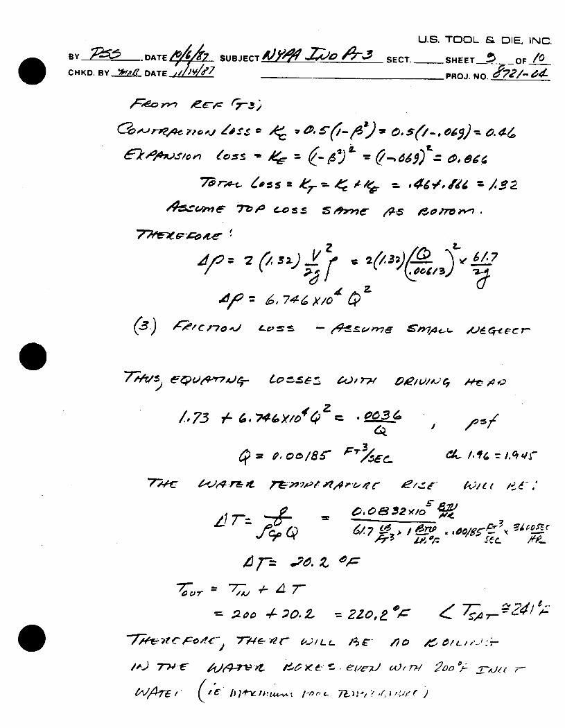
7' r,-, ,., Lss a er 4 = /_ 2
- 9~ /,9ne, 7Z' 405 Sx/ e- ,4
L7 se41 lJ7-
ZI 7-='L
= ooL o.. :2Zzo,e # "7:,..,C2
7 - t')/L / -- /lo 1- 4)L,,'- 2E0
7.
U.S. TOOL & DIE. INC.
BY._______ DATE 7SUBJECT4 SECT. ___- SEET / OF _
CHKD. BY %life DATE_____ ________________PROJ. NO.A7,o
/3 ,.~ o
, -- -e "01 H- -- '
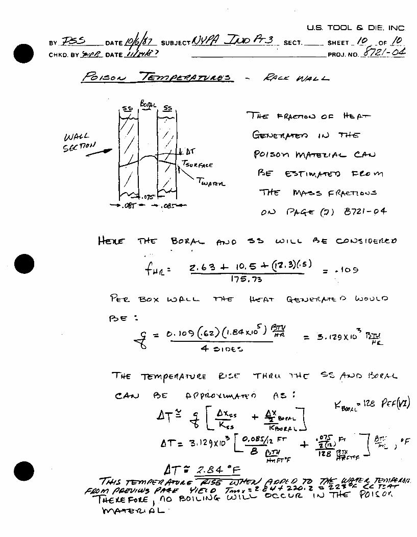
P015'0-r VwiAc C4-'-j
(4Jp1k~t
O~S *~- -~ .(5721-04-
Z.s3- 1( = .Io9
Fe-c
t4
CAtj F PE
(1 .84 Y-.tO ).at e. ) I f.
P ,1 "r y t. .. -'.,
(A s
L T + r bot.-t
S"~ z ~V/-
0, oe& Fr LlVT= ,3 ,5
!IT' .7" .. 4-*
WNrVA-.A to L.. •
".,s l-r -
tie ol
175, 17
- ,, ,' C- ./ -z.. -
00 P -CT P)
krxir -1H-c 13of-A-., ftvjo 5, tD. w t- ta -e C-0 os I ot apt 10
U.S. TOOL & DIE, INC.
13Y __- DATE S UBJ E CT _S.L~ Er SC T. -- HEE OF CHD. BY_' DATE ,/ V, ?,/7.......... PROJ. NO. -(5e- 04
e&--7&-oJ Z--g,
P/'e ,A. '2A-tt'J,.e ..,
E_ i,, Z. / ,Fs ,, .#'=--- r~p,,,_, TV,~e e u ..t
Question IVl
Why the fuel assembly drop height is 20" instead of 36" normally used for such analysis?
Response to Question IVl
It was determined that it would not be possible to raise a fuel assembly higher than approximately 19 inches over an installed maximum density rack. This determination was based on:
(a) Actual measurements with the manipulator crane in the full up position and a fuel assembly suspended from the fuel handling tool.
(b) The installed rack being at the minimum elevation permitted by the adjustable screw pedestals.
The 20 inch drop height used in the analysis is therefore a bounding condition.
Question IV.2
Since the analysis performed for a straight drop of a fuel assembly through an individual cell shows that the weld between the bottom plate and cell wall fails, provide calculations to demonstrate (a) the integrity of the pool liner to accommodate the dropped fuel assembly, and (b) the integrity of the fuel assembly under the impact.
Response to Question IV.2
(a)
The residual striking energy of the missile (fuel assembly) is much less than the strain-energy of the target (0.25" thick liner plate supported continuously on concrete). Confirmatory calculations were performed for the drop of the fuel assembly through water alone and showed that the liner plate thickness would not be penetrated. The Ballastic Research Laboratory formula for steel target thickness was used. This confirms that the integrity of the pool liner would be maintained if a fuel assembly is dropped on it.
bIl
Section 14.2.1 of the Indian Point 3 FSAR addresses fuel handling accidents, including analysis of dropping a fuel assembly vertically onto a rigid surface. This analysis indicated that the buckling load on the fuel rods was below the critical buckling load and stresses in the cladding were below yield. The loads induced by dropping a fuel assembly vertically through an individual rack storage cell would be less than the cas analyzed for the FSAR due to the kinetic energy absorbed by the cell bottom plate. The results of the previous FSAR fuel drop analysis, therefore, remain valid.
Question IV.3
Provide the basis or fuel drop analysis. buckling coefficient
source for the buckling stress equation used for the Also provide Reference #13 which developed the Kc•
Response to Ouestion IV.3
Attached please find a copy of Reference #13 as requested. The buckling stress equation used for the fuel drop analysis was derived from the classical theory of buckling of thin plates as may be found in "Theory of Elastic Stability" by S.P. Timoshenko and J.M. Gere. The adaptation of the classical theory for the present application is described in detail in the reference provided, under the chapter titled "Theoretical Buckling Predictions, Test Observations and Correlations."
APPENDIX B
FUEL BOX CRUSH TESTS
REPORT AND CALCULATIONS
907F17
-TYPICAL
FOR FUEL STORAGE RACKS WHICH
HAVE CELL TO CELL CONSTRUCTION
WITH NO INTRACONNECTING STRUCTURE
JANUARY, 1980
SP..,f FUEL STORAGI ,ACKS
FUEL BOX CRUSH TESTS
MAXIMUM DENSITY RACK DESIGN
TYPICAL PWR FUEL
REPORT AND CALCULATION 907F17
COVER SHEET: Conforming to WAI QA-8-75-100, No. Q-6 Section 4.0.
TRACEA.BLE DESIGN INPUT: ITLS Report No. 27852 (Attached).
PURPOSE: Determine fuel rack response to impact or external loading conditions based on box crush test results for two MDR box sections.
ASSUMPTIONS:
FERENCES:
CONCLUS IONS:
Quasi-static compression tests on corner and fully loaded MDR box sections can be used to access the extent of damage in the actual rack array. In particular, some of the box crush test results must be predictable and the four requirements listed on page 2 should be justified.
Den Hartog, Faupel, Shanley, and Roark listed on page 24.
The box crush test buckling forces are theoretically predictable within estimated undertainties and the four requirements of page 2 are justified. The actual rack array will buckle near allowable yield limits. The extent of vertical deformation in the rack array can be estimated conservatively high using a specific absorbed energy estimate of 1250 ft-lbs per inch deformation per square inch contact area. Lateral damage to boxes adjacent to the impacted one(s)will typically be small in comparison.
PREPARED BY: I. - ,L /,o
REVIEWED BY://6
APPROVED BY: -,
This reportxs applic' a to a I PWR - MDR designs.
BY, EAF 9o CHKD. BY 4~, 907F17
VSPENT FUEL STORAGE RACKS
FUEL BOX CRUSH TESTS MAXIMUM DENSITY RACK DESIGN
TYPICAL PWR FUEL
INTRODUCTION AND SUMMARY
The typical Wachter spent fuel storage Lox for a PWR maximum density rack (MDR) design measures 9" square and is fabricated from 1/8" thick (.120 - .125") 304 stainless steel sheet. To a~sess the extent of damage resulting from external impact loadings (e.g., fuel, cask, or gate drop accidents), two MDR box sections approximately 15h" in length were fabricated and compressed quasi-statically at deformation rates ranging from 25 to 200 mils/minute.
The first box was corner loaded over one quandrant and deformed 4" - equivalent to a total absorbed energy of 6000 ft-lbs. The second box was fully loaded in compression and deformed 3" - equivalent to a total absorbed energy of 11,000 ft-lbs.
The forces required for buckling are in good agreement with theoretical predictions and are nearly independent of the box length. Apart from inflections not exceeding 30%, the absorbed energy versus deflection curves are linear, defining an average force 60 to 65% of the buckling force.
TEST CONSIDERATIONS AND CONDITIONS
It is desired to have a relatively simple test that provides information on a variety of external loading
-1-
B E F boole'
CHKD. BY_2_Z
907F17
and impact conditions. Although testing of partial rack arrays could yield a considerable amount of information, a large number of arrays would need to be constructed and tested to cover uncertaintics and varieties of accident loading conditions. In addition, tonnage capacities and test bed areas limit both the applied forces and the number of fuel boxes that can be tested.
It is recognized that for any postulated accident, the potential energy prior to impact is known or easily calculated. This energy is approximately mgh, where a is the mass of the impacting missile, g thi acceleration due to gravity, and h is the height of the drop. Neglecting the bouyancy due to the water in the fuel pool, the rack must absorb this energy plus an additional mg6 where 6 is the vertical deformation. Since 6 is generally much smaller than h, it >could be neglected as a first approximation and then determined with one iteration.
In order for the crush test results on single boxes to be used to estimate the extent of external loading damage in the actual rack array, some of the crush test results must be theoretically predictable. It is also desirable that the following be established:
I. The extent of damage is locally limited. 2. The absorbed energy is a known and simple (semiempirical) function of axial deformation. 3. The test results and the actual rack array behavior are not strongly length dependent. 4. The test results can be used for accurate (or conservatively high) estimates of the actual rack array deformation.
-2-
CHKD. B
907F17
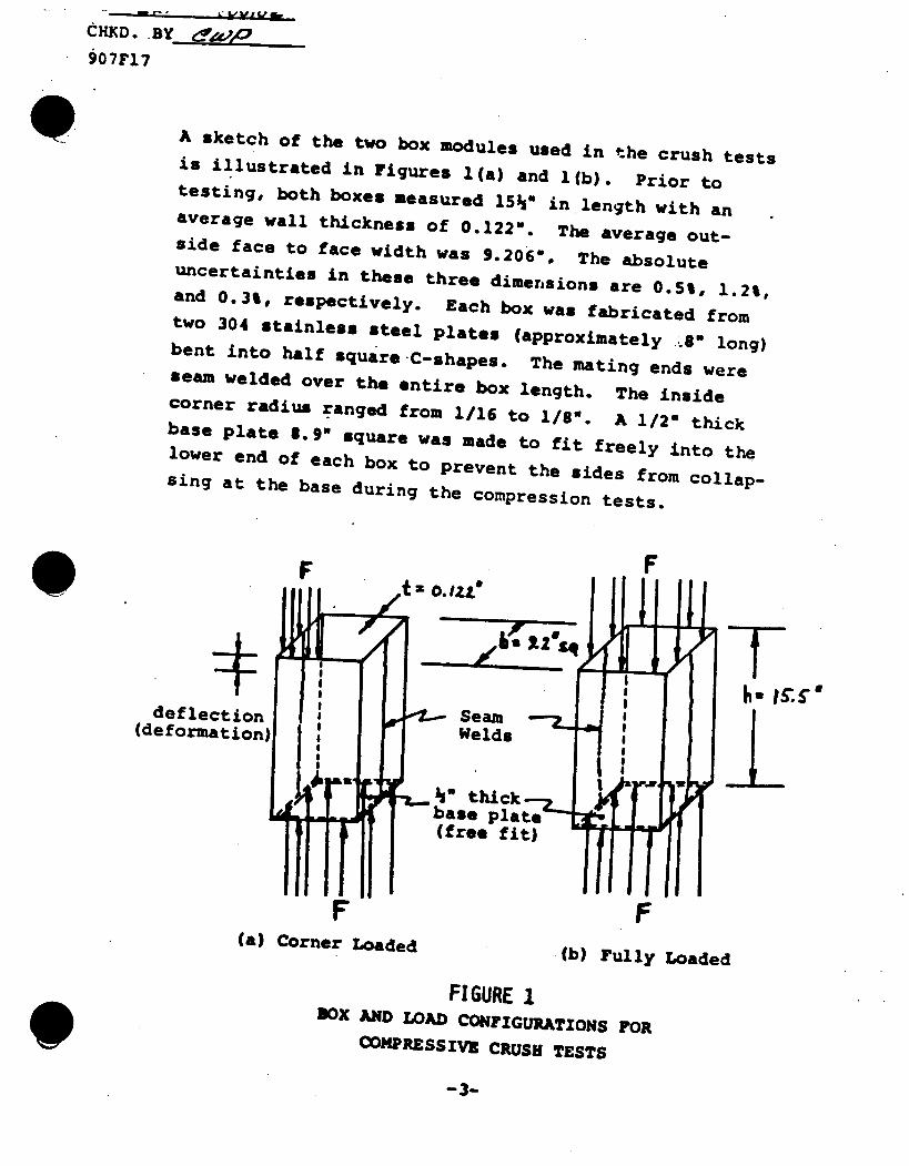
A sketch of the two box modules used in the crush tests is illustrated in Figures l(a) and l(b). Prior to testing, both boxes measured l5hQ in length with an average wall thickness of 0.1220. The average outside face to face width was 9.206', The absolute uncertainties in these three dimensions are 0.5%, 1.2%, and 0.30, respectively. Each box was fabricated from two 304 stainless steel plates (approximately '. long) bent into half square C-shapes. The mating ends were seam welded over the entire box length. The inside corner radius ranged from 1/16 to 1/8". A 1/2" thick base plate 8.9" square was made to fit freely into the lower end of each box to prevent the sides from collapsing at the base during the compression tests.
F F, ~t .1zLe
[ (free fit)
F (a) Corner Loaded .(b) rully Loaded
FIGURE I BOX AND LOAD CONFIGURATIONS FOR
COMCPRESSIVE CRUSH TESTS
-3-
BY. £EF toopz
CHXD. BY
907F17
The first box was corner loaded in compression over one quandrant at the top of the box, approximately 4.5" along two adjacent sides. The base was fully supported in the direction of the applied force and constrained from bending laterally by the presence of the 1/2" thick plate. This box was axially deformed 4.0" over the loaded corner. The second box was supported at the base in a similar manner but fully loaded at the top. The contact area being four times larger for this box necessitated using a test machine with a larger tonnage capacity (up to 60 tons). This box was compressed 3.1". Deformation rates for both tests ranged from 25 to 200 muls/minute depending upon the frequency at which the force-deflection (or deformation) measurements were taken.
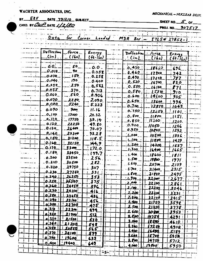
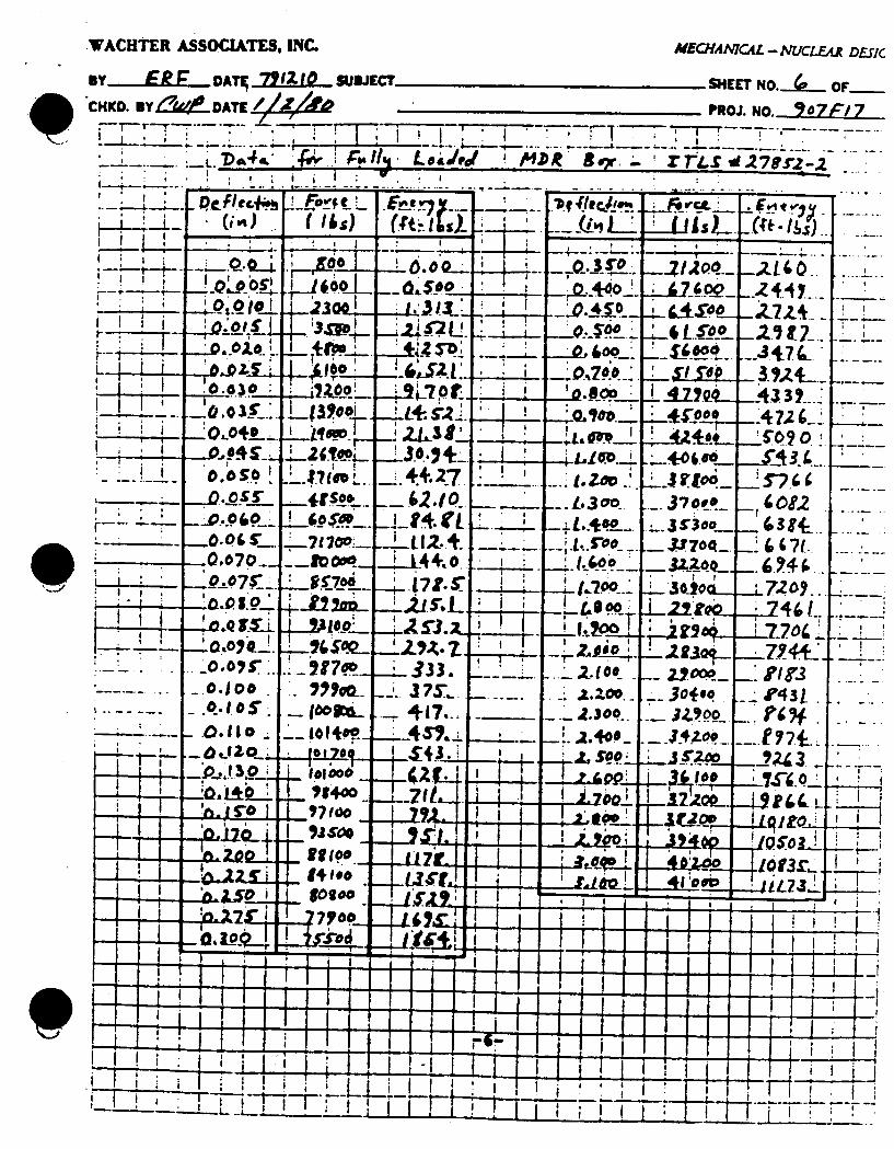
Both tests were conducted during the morning of Dec. 7, 1979 at Industrial Testing Laboratory Services, Inc., RIDC Park, Pittsburgh, PA 15238 under the supervision of Dr. G. T. Home (ITLS). A Wachter Associates, Inc. (WAI) representative (E. R. Frantz) witnessed the test and independently recorded force-deflection data. The ITLS test reports are attached as an appendix to this report. The WAI data is given on the following two pages. The tabulated energies (E -IFd6) were determined by numerically integrating the force-deflection (deformation) data following the trapazoidal method approximation. Plots of F vs 6 and E vs 6 for both tests are given on the three pages following.
-4-
WACHTER ASSOCIATES., INC. MECHAAML - NUCLE"R DESKc
By ElR DATE 7912/0 SUBJECT SHEET NO.... OF SCHKD. BY DATE 4& Z P PROJ. NO._ 27F/'7
. -_ Dac A eC., V r k.Leade $'35)t loe.:. r ti $ : -z785,4-
. .
----- F
ml-
r'.f(eC+4.i 1 vr
__(r. ____ *IS .. ). ,OL _
.... Qto
. .o qo__ 0. oo
.oo. ... . 0 .0 _. .0,0t0_ _.0.po_
.o10 ! _ .L O,,L0 _. o
o-o .
. 0.2.0.
37o.
S177o...
... 3!ooo
• "_250
... zes " *3.45 1 335.0-
0.0 _ ... 0.400
.6-713. _0.90¢. _. 2.o~o.
FII. If,,
20.32, I...3301+ - 49.to _70.07
1..L72, 0.
._3o7
I I .- - *. - I
A......
----- I- -
_. l-. _-m_
... 100
1900
_.2o L-I
... ... . I
.E....g oo
,--Z07m_ ,aL+
2-.--+ttie__
I I
_.0...4 3o_
(.too
. 70 .
-. (.(O0__
.... e, o :
• . 00..
-..
__'ff i
_.LC : .-... _,.__
i94 J7 L _- "
+__ _t .I 0 7!
__U L_ .I '._ _
-" 197 _/ I--
- 31- _ _ _.
_.2R/.. .4..j
_.2~L. 1 , -
,-A_cI S'-L
WACHTER ASSOCIATES, INC. MECHANMCAL - NUCLEAR DESKC
m RY .E " DATI 7111O SUBJECT SHEET NO.-_( OF.
CHKO. B l-&.. DATE PROJ. N.7-.. . "-" -r -T . .. . '- , . .. •l----. -- .. .. .-* - a---+ ... . -- . . . . - . -- ... .
- ._'.4a ,. r, Ledrd M.DR BO' Y. rfl-s.270r2.-.2
goo -21.0 1 . L. /6 ..
0: 0 1-, L"4O0. t
.J. ' .. O;O. PS. 2J e:l. 4lt ' -- )I.. d..0 _o ,' ..Frc . 7, I '.... .') (/s (Ft,I ~ ~ a .. A6 , • ... -.....sJ 'I a I I * ,
P- . - --- -. - ..... - -,. _ .... 8 - L - - -. 3 ,_ , .;Q,, "t-- ,. oo, ,, , ...._ ----- •4 2L~ ... .
.. ... 0 -Ill...... ...... :o j .o, '3i.Soop _ ,L o_.. aa a,'~so !_lt._ .Z 3 -tSO... oL_.. :_€ o -+. . j 5_. 'l ' + oo_ _4a + : L
I , ' a
LiL3 _L~.o.o1o_+ _£.._ L;.sS. i : aQ~e._ * 4$'0Z * _A?2 o ,
L144 - -- Z.t.--3O +, -=. o._j l OL4L" ; Ld ! ~Z. , •LL~ A . + " ;O?
..Qo7o._
I a..to
"O~ IL
_0.0 _.
.0. II o.
.4.,(0+ L.
-71 700:
. oo.
-:~ 0
Mat
'27T _ .1.. s.
jI4 . 3 13.
; J7S... --"117...
a a - -~-
TTV
014. -4 .. : , .L.l oi7.e I 4 . ,
__. , o c-i~.r0
-;d.1oo.
.2.00..
* so .._
.... 37o,,,
S.3-_7om
-- 3200
- $zo,
A o__. __.36io~ _
5"
72O+..
r- 431
.. 3S.. +. ULJ0t _j?
-i T: SI IT
I r -
%-P
-1~ -a I
a I
'a
* I 7F1 m -1---
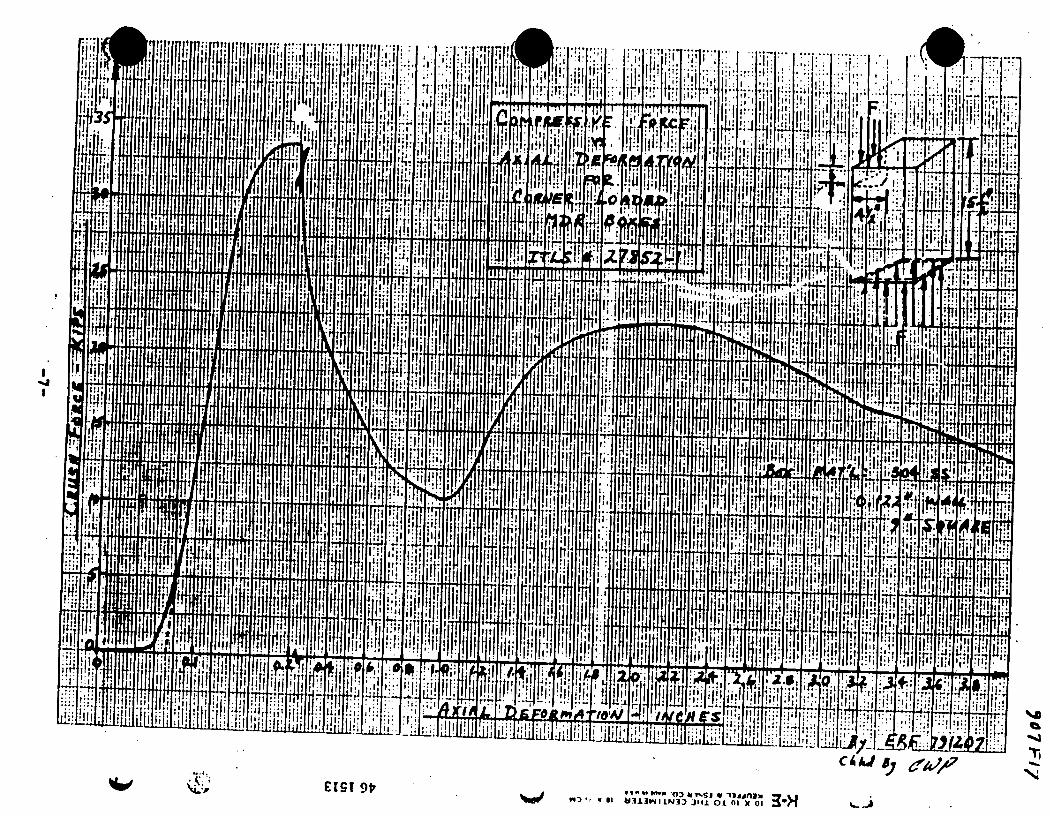
'l ,I II*, I . , ,. . J1 : '
?, ~~ ~ Ol.,..- . Ju"l. .
III]
17 II
.jI
0i'r;hII
C lr 9t"33.LI 04L3-1 314L 01 0 1 x 01 3
, .8.
L I 1 11 A
lif. . .............
711
CAAJ
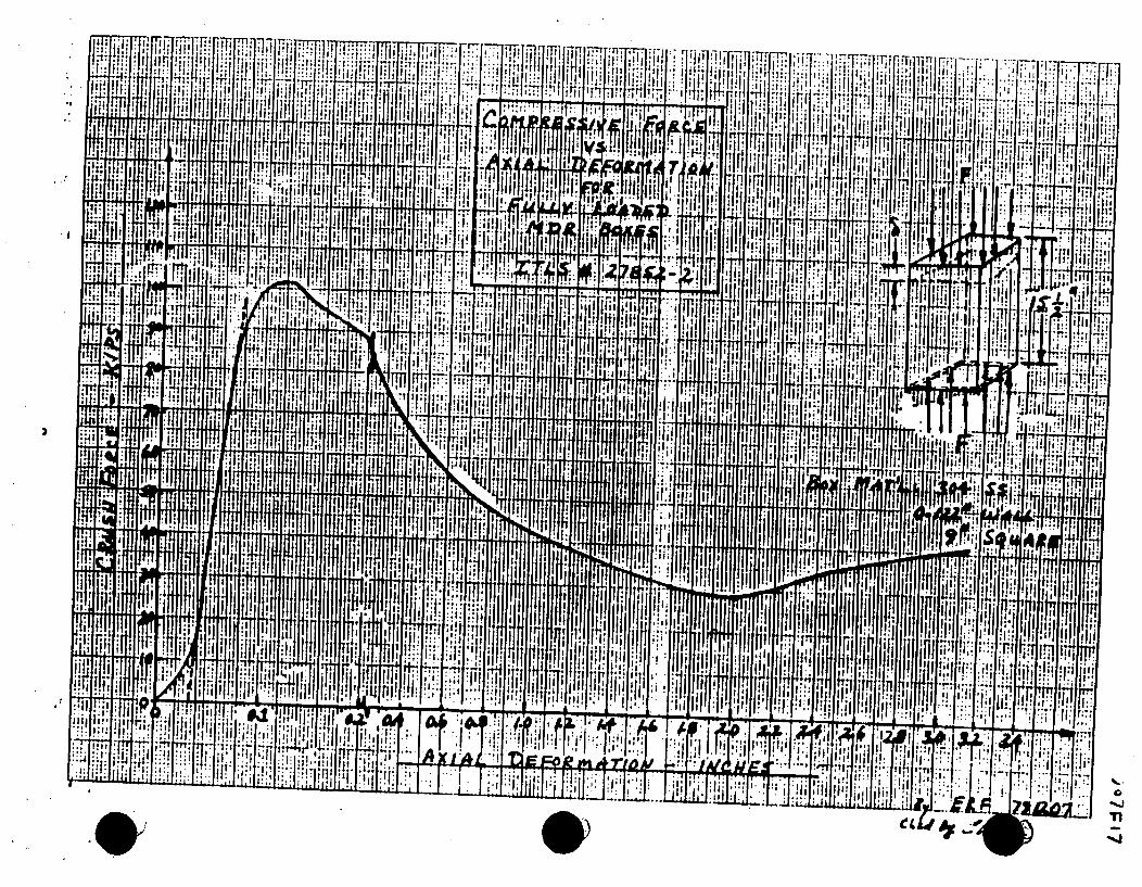
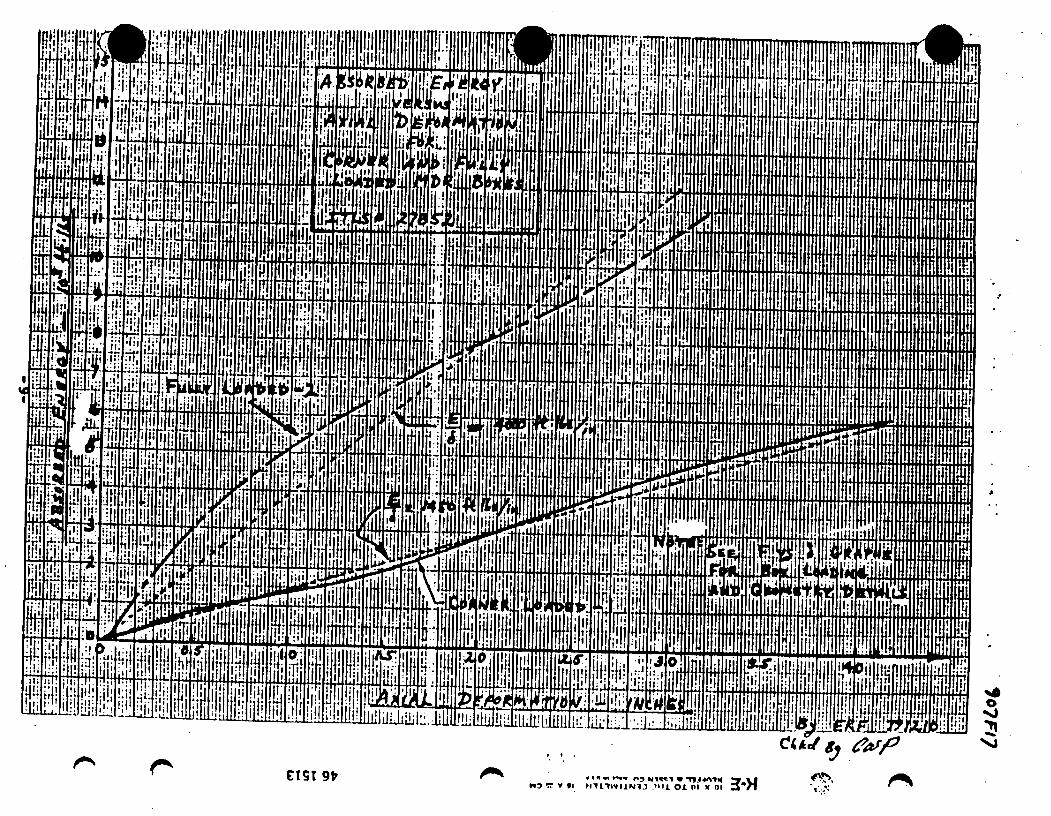
'lAl-
-4I-E..L
-f*F
!.hijaLII~i; 1 EIEZs
CIST 9V'W3r, I V 'll J I IN13 '11 01 111a l 30H
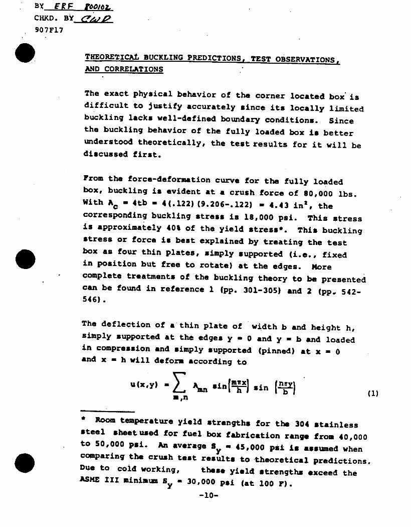
B)( ERF VoO/OL C HKD. B
907F17
THEORETICAL BUCKLING PREDICTIONS, TEST OBSERVATIONS,
AND CORRELATIONS
The exact physical behavior of the corner located box is difficult to justify accurately since its locally limited buckling lacks well-defined boundary conditions. Since the buckling behavior of the fully loaded box is better understood theoretically, the test results for it will be discussed first.
From the force-deformation curve for the fully loaded box, buckling is evident at a crush force of 80,000 lbs. With Ac - 4tb - 4(.122)(9.206-.122) - 4.43 in', the corresponding buckling stress is 18,000 psi. This stress is approximately 40% of the yield stress*. This buckling stress or force is best explained by treating the test box as four thin plates, simply supported (i.e., fixed in position but free to rotate) at the edges. More complete treatments of the buckling theory to be presented can be found in reference 1 (pp. 301-305) and 2 (pp. 542546).
The deflection of a thin plate of width b and height h, simply supported at the edges y - 0 and y - b and loaded in compression and simply supported (pinned) at x - 0 and x - h will deform according to
U(x,y) A.~ sin(mA~) sin . ) 1 min
* Room temperature yield strengths for the 304 stainless steel sheetused for fuel box fabrication range from 40,000 to 50,000 psi. An average SF - 45,000 psi is assumed when
comparing the crush test results to theoretical predictions. Due to cold working, these yield strengths exceed the ASME III minimum Sy - 30,000 psi (at 100 F).
-10-
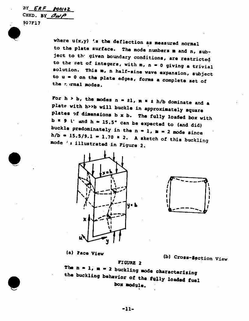
£R .F ,ietZ CHKD. BY
907FI7
where u(x,y) 's the deflection as measured normal to the plate surface. The mode numbers m and n, subject to thr given boundary conditiona, are restricted to the set of integers, with m, n - 0 giving a trivial solution. This s, n half-sine wave expansion, subject to u - 0 on the plate edges, forms a complete set of the r. rmal modes.
For h > b, the modes n = ±I, m w I h/b dominate and a plate with h•>b will buckle in approximately square plates if dimensions b x b. The fully loaded box with b 2 9 L' and h = 15.5" can be expected to (and did) buckle Predominately in the n - 1, a - 2 mode since h/b - 15.5/9.1 - 1.70 a 2. A sketch of this buckling mode "s illustrated in Figure 2.
volt
(a) Face View (b) Cross-Opction view
The n = I# a 2 buckling mode characterizing the buckling behavior of the fully loade4 fuel
boar nodule,
-11-
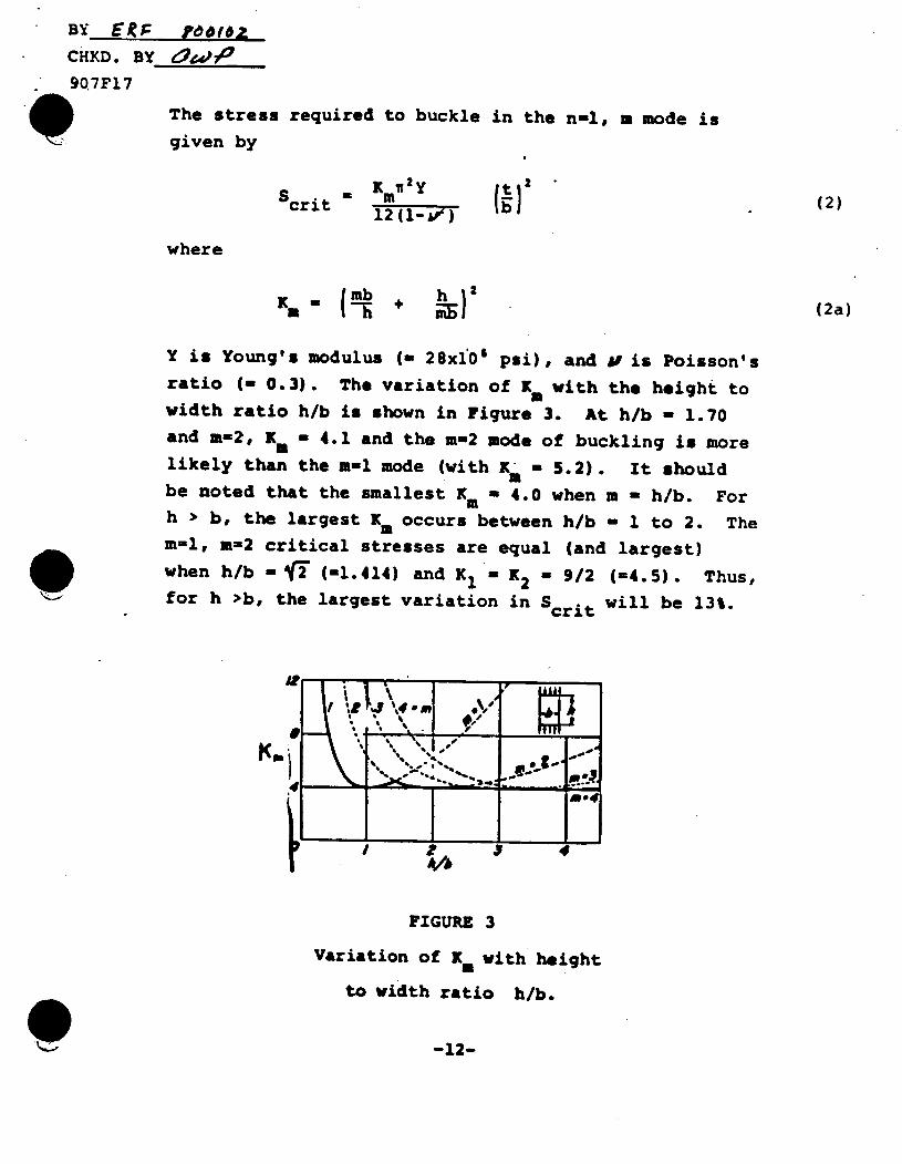
BY. E.F 'e616z CHKD. BY O&OP
9Q7F17
The stress required to buckle in the n-i, a mode is given by
Sci X Xit 2Y (2) Scrit 1 1- 1 112
12(1_VT"
where
K. _ (I + h(2a)
Y is Young's modulus (- 28xi'6 psi), and l is Poisson's ratio (- 0.3). The variation of K with the height to width ratio h/b is shown in Figure 3. At h/b - 1.70 and m-2, K. - 4.1 and the m-2 mode of buckling is more likely than the m-1 mode (with K - 5.2). It should be noted that the smallest Km - 4.0 when m - h/b. For h > b, the largest K. occurs between h/b - 1 to 2. The mnl, m-2 critical stresses are equal (and largest) when h/b -1 (-1.414) and K l= K2 - 9/2 (-4.5). Thus, for h >b, the largest variation in Scrit will be 13%.
ki T ! j-It FIGURE 3
Variation of K with height
to width ratio h/b.
-12-
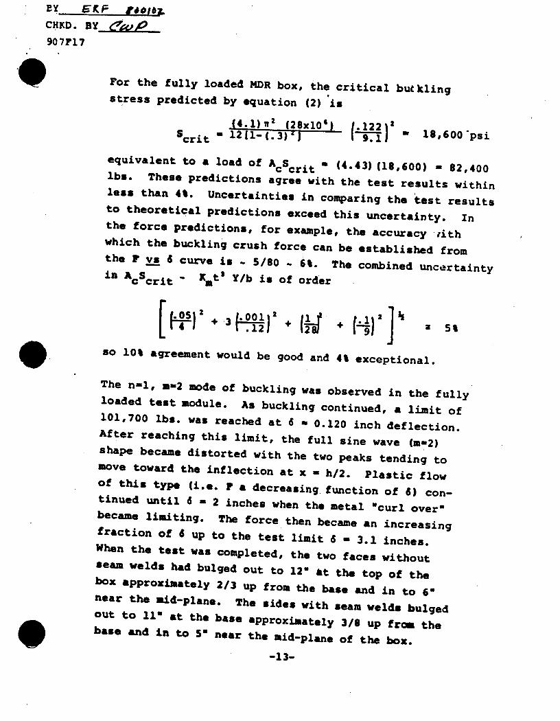
EY ET F t$01h1i
CHKD. By___ e,,p 907F17
For the fully loaded MDR box, the critical butkling stress predicted by equation (2) is
A4. 1) 2 (28x10') . .122)2 2 Scrit - 2[1-(.3)'J I 9.11 18, 6 00psi
equivalent to a load of AcScrit - (4.43)(18,600) - 82,400 lbs. These predictions agree with the test results within less than 40. Uncertainties in comparing the test results to theoretical predictions exceed this uncertainty. In the force predictions, for example, the accuracy ,ith which the buckling crush force can be established from the F vs 6 curve is - 5/80 - 61. The combined uncertainty in ACScrit - Xmt2 Y/b is of order
cc t.12 (5
so 10% agreement would be good and 4% exceptional.
The n-l, m-2 mode of buckling was observed in the fully loaded test module. As buckling continued, a limit of 101,700 lbs. was reached at 6 - 0.120 inch deflection. After reaching this limit, the full sine wave (m-2) shape became distorted with the two peaks tending to move toward the inflection at x - h/2. Plastic flow of this type (i.e. F a decreasing function of 6) continued until 6 - 2 inches when the metal "curl over" became limiting. The force then became an increasing fraction of 6 up to the test limit 8 - 3.1 inches. When the test was completed, the two faces without seam welds had bulged out to 12" at the top of the box approximately 2/3 up from the base and in to 6" near the aid-plane. The sides with seam welds bulged out to 110 at the base approximately 3/8 up from the base and in to 50 near the aid-plane of the box.
-13-
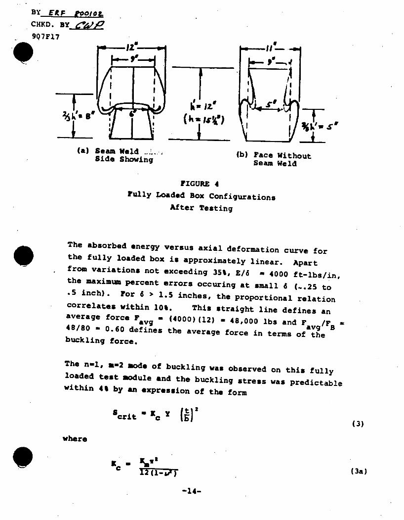
BY ERF tooto . CHKD. 907F17
(a) Seam Weld (b) Face Without Side Showing Seam Weld
FIGURE 4 Fully Loaded Box Configurations
After Testing
The absorbed energy versus axial deformation curve for the fully loaded box is approximately linear. Apart from variations not exceeding 35%, E/6 - 4000 ft-lbs/in, the maximum percent errors occuring at small 6 (-.25 to .5 inch). For 6 > 1.5 inches, the proportional relation correlates within 10%. This straight line defines an average force Favg - (4000)(12) - 48,000 lbs and F avg/F = 48/80 - 0.60 defines the average force in terms of the buckling force.
The n-l, u-2 mode of buckling was observed on this fully loaded test module and the buckling stress was predictable within 4% by an expression of the form
crit - C ((3)
where
12 (3a)
-14-
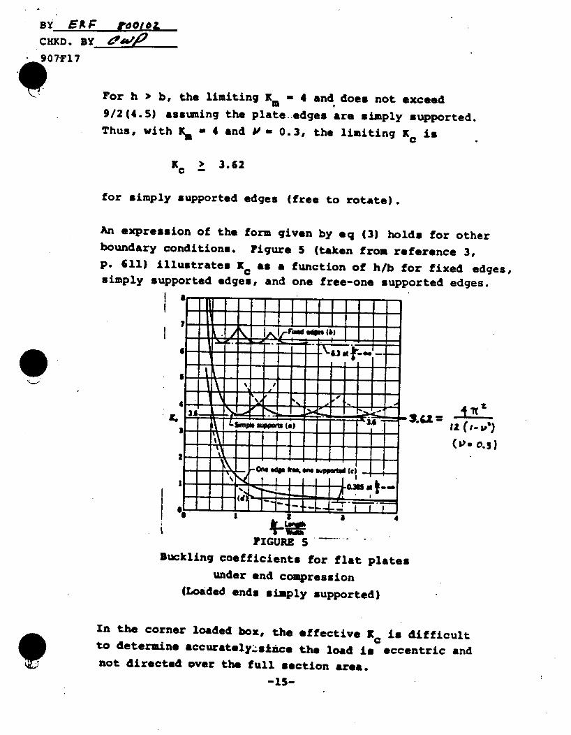
BY ExF pootea
CHKD. BY
907"F17
For h > b, the limiting Km - 4 and does not exceed me
9/2 (4.5) assuming the plate edges are simply supported. Thus, with Km - 4 and Y - 0.3, the limiting Kc is
Kc > 3.62
for simply supported edges (free to rotate).
An expression of the form given by eq (3) holds for other boundary conditions. Figure 5 (taken from reference 3, p. 611) illustrates Kc as a function of h/b for fixed edges, simply supported edges, and one free-one supported edges.
iI !iiiii 1* I1 I I *~
1i 11 1 1 ^- I I I -- lr
IR Ii
IL25
|, !, , , , .
Ii (i-~,')
(&'. 0.3)
a 3
FIGURE 5 . Buckling coefficients for flat plates
under end compression (Loaded ends simply supported)
In the corner loaded box, the effective K4 is difficult to determine accurately-siuce the load is eccentric and not directed over the full section area.
-15-
!
BY ERF P00/IL
CHKD.BY
907F17
P If the unloaded portion offers some support against rotation, then Kc will likely fall within the range 3.62 to 6.3,where the latter signifies fixed edges. The buckling stress will then fall between
(3.6) (28xl0) 1.12 Sb < (6.3) (28x10) 1.122 2
or
18,000 < Sb < 32,000 psi
and since Ac 3 bt 8 4.43/4 = 1.11 in 2 , the test buckling
force should fall between
20,000 lbs 4 Fb < 35,000 lbs.
The observed proportional limit was approximately 27,500 lbs, approximately half way between these theoretical limits, defining an effective Kc n 5.0 for the corner
loaded box.
As the box buckled, the loaded side with a seam weld deflected inward at the top of the box and the side without deflected outward. Although the seam welded sides in the fully loaded box also deflected inward at the top, there is no reason to suspect that--this trend will always occur. In the fully loaded box, neither mean weld has failed. In the corner loaded box, the
seam weld tore when 6 a 1 inch, far beyond the deflection 6 U 0.2 inch at the peak compressive force.
The 1 vs 8 curve for the corner loaded box Wes through two relative maxima and one minium. At the second 3 maximum, 1' 22,000 lbs. and 6 = 2.0 inches. The minimum
-16-
BY EO F todoL
CHKD. BY dA ..
907F17
at 6 a 1 inch is F - 10,500 lbs, approximately half as large. This variation was caused by the metal folding over or bending (which required little force to cause deflection) followed by a compressive loading on the flattened folds (which required larger forces). The force at this second relative maximum (a 22,000 lbs) was approximately 75% of the peak crush force ("34,000 lbs at 8 a 0.20 inch).
It is postulated that the second maxima exhibits characteristics of column buckling due to the eccentric loading since the final box configuration shows a net outward deformation superimposed on the inward-outward plate buckling deformation. The familar secant formula for colmn buckling (see e.g. Ref. 2, p. 510 or Ref. 4, p. 261) is used to predict this stress denoted SC P
where e is the equivalent eccentricity, c is the distance from the central axis to the position of peak stress, and r is the section radius of gyration. For the principal axes of the square section of side b with thickness t,<b, r - b/F/. Taking e a c a b/2, the eccentric ratio. ec/r 2 - 3/2. With 8c N 20,000 psi, Y • 28 x 106 psi h. a5.50, and r s b/F6 9 9fV6 - 3.7 in, sec
sec (.056) a 1.00; the critical stress Sc 3 (2/5) S y (.4) (45,000) - 20,000 psi. The corresponding force is (20,000) (1.11) a 22,000 lbs, in agreement with the force near the second maxima. (This precise agreement, however, was not expected.)
-17-
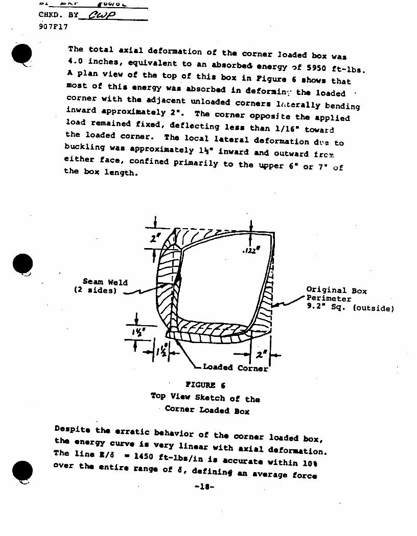
CHIM.By 907F17
The total axial deformation of the corner loaded box was 4.0 inches, equivalent to an absorbed energy of 5950 ft-lbs. A plan view of the top of this box in Figure 6 shows that most of this energy was absorbed in deformin, the loaded corner with the adjacent unloaded corners liLterally bending inward approximately 2. The corner opposite the applied load remained fixed, deflecting less than 1/161 toward the loaded corner. The local lateral deformation due to buckling was approximately 1%" inward and outward frcn either face, confined primarily to the upper 6" or 7" of the box length.
Seam ldes Original Box (2 sides) Perimeter 9.2" Sq. (outside)
Loaded Corner
FIGURE 6 Top View Sketch of the
Corner Loaded Box
Despite the erratic behavior of the corner loaded box, the energy curve is very linear with axial deformation. The line Z/6 = 1450 ft-lbs/in is accurate within 10% over the entire range of d, defininf an average force
-18-
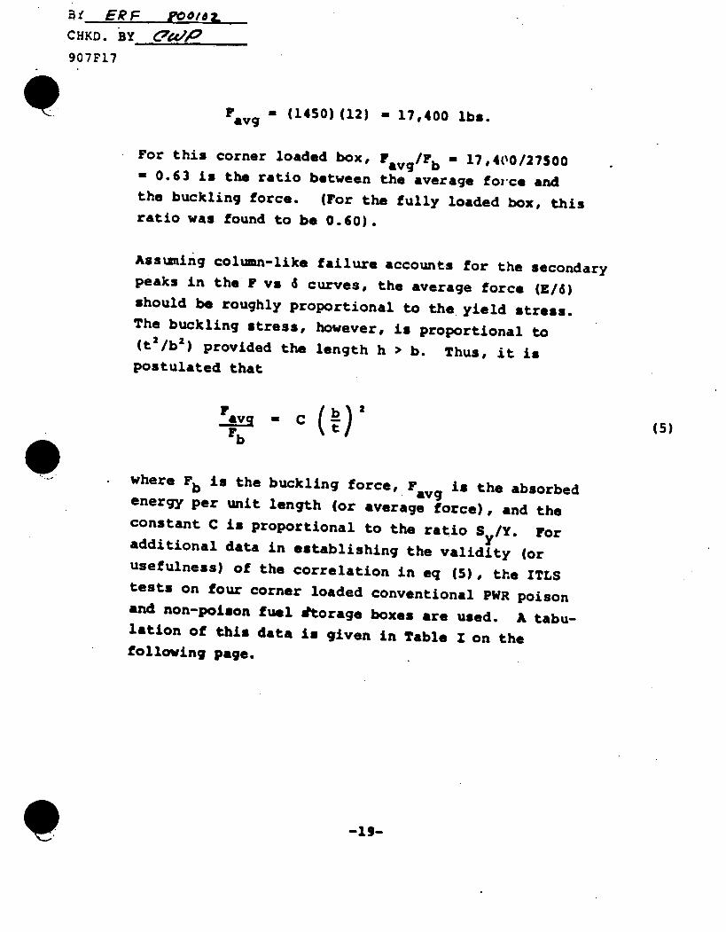
Bi ERF roolez
CHKD. BY C'PWP
907F17
F - (1450) (12) - 17,400 lbs. avg
For this corner loaded box, Favg/Fb - 17,400/27500 - 0.63 is the ratio between the average force and the buckling force. (For the fully loaded box, this ratio was found to be 0.60).
Assuming column-like failure accounts for the secondary peaks in the F vs 4 curves, the average force (E/d) should be roughly proportional to the yield stress. The buckling stress, however, is proportional to (t2/b2 ) provided the length h ) b. Thus, it is postulated that
F avg C b (5) rb t
where Fb is the buckling force, Favg is the absorbed energy per unit length (or average force), and the constant C is proportional to the ratio S y/Y. For additional data in establishing the validity (or usefulness) of the correlation in eq (5), the ITLS tests on four corner loaded conventional PWR poison and non-poison fuel torage boxes are used. A tabulation of this data is given in Table I on the following page.
-19-
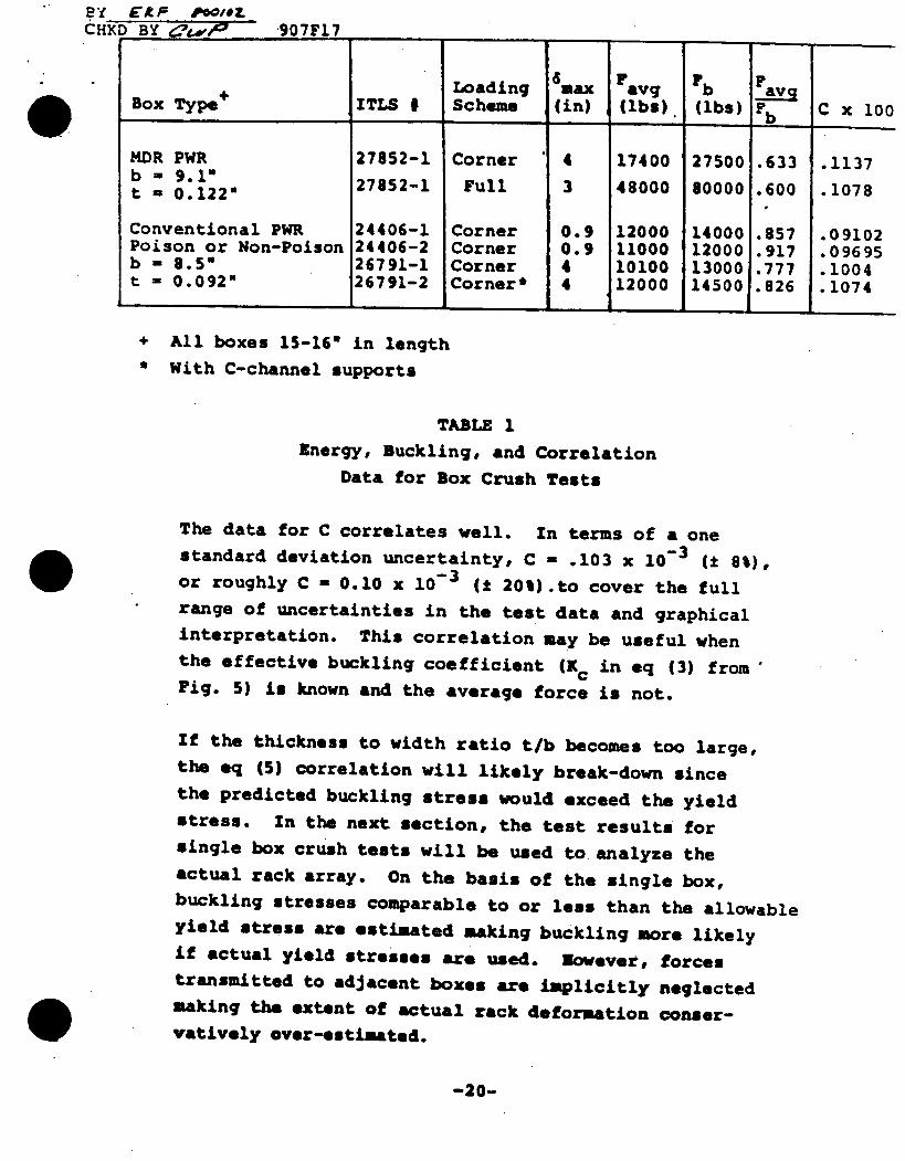
By CAP P00/#L CHKD BY aley47 907F17
Loading 6max F avg Fb ay Box Type+ ITLS # Scheme (in) (lbs). (lbs) Fb C x 100
MDR PWR 27852-1 Corner 4 17400 27500 .633 .1137 b- = .1" b 0.122" 27852-1 Full 3 48000 80000 .600 .1078
Conventional PWR 24406-1 Corner 0.9 12000 14000 .857 .09102 Poison or Non-Poison 24406-2 Corner 0.9 11000 12000 .917 .09695 b - 8.5" 26791-1 Corner 4 10100 13000 .777 .1004 t = 0.092" 26791-2 Corner* 4 12000 14500 .826 .1074
+ All boxes 15-160 in length ' With C-channel supports
TABLE 1 Energy, Buckling, and Correlation
Data for Box Crush Tests
The data for C correlates well. In terms of a one standard deviation uncertainty, C - .103 x 10- 3 (t 8%), or roughly C - 0.10 x 10 - 3 (1 20%).to cover the full range of uncertainties in the test data and graphical interpretation. This correlation may be useful when the effective buckling coefficient (Kc in eq (3) from Fig. 5) is known and the average force is not.
If the thickness to width ratio t/b becomes too large, the eq (5) correlation will likely break-down since the predicted buckling stress would exceed the yield stress. In the next section, the test results for single box crush tests will be used to analyze the actual rack array. On the basis of the single box, buckling stresses comparable to or less than the allowable yield stress are estimated making buckling more likely if actual yield stresses are used. Nowever, forces transmitted to adjacent boxes are implicitly neglected making the extent of actual rack deformation conservatively over-estimated.
-20-
BY jVKF f'0018L
C 1flD. YAt 907F17
APPLICATIONS FOR ACCIDENTAL LOADINGS
A typical M4DR fuel rack for PWR spent fuel consists of an array of 100 to 200 boxes, 1/2 to 3/4 of which may house fuel. Pairs of spot welds at 5 to 8 axial locations attach faces of neighboring boxes together. The first and last pairs of spot welds are approximately 2" from the top and bottom of the 13' long box, respectively. The remaining pairs distribute over the box length weighted near the base where stresses are highest. Additional strength is offered by continuous fusion welds around the top and bottom edges of each box interface.
Forces required for plate-like buckling in the upper two inches of the box (between the fusion weld and top pair of spot welds) are excessive since the effective h/b ratio is small. It is more likely that yield would occur there unless the force can be transmitted to other sets of spot welds. Since these sets of pairs are separated by distances h > be buckling in an interrack position may be possible. The boundary conditiogs here, however, are different than those of the fully loaded test module and weld attached walls are more likely to deflect away from each other instead of moving together as a slab with effective thickness 2t. Referring to Figure 7, the following estimation will establish the reason for this.
-21-
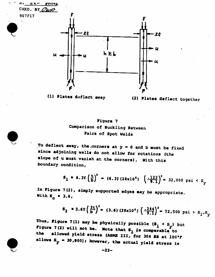
CHKD. By 60 907F17 F
it Z
U U
(1) Plates d-flect away (2) Plates deflect together
Figure 7 Comparison of Buckling Between
Pairs of Spot Welds
To deflect away, the.corners at y - 0 and b must be fixed since adjoining walls do not allow for rotations (the slope of u must vanish at the corners). With this boundary condition,
S 6.3Y() - (6.3) (28xlO) 2 32,000 psi < Sy
In Figure 7(2), simply supported edges may be appropriate. With Kc a 3.6,
S2 "3.6Y(-)- (3 .6)(28x10') (.4) 72,500 psi >St
Thus, Figure 7(1) may be Physically possible (al < S ) but Figure 7(2) will not be. note that a, *a comparable to the allowed yield stress (ASmE III, for 304 18 at 1000F allows Sy - 30*,00), however, the actual yield stress is
-22-
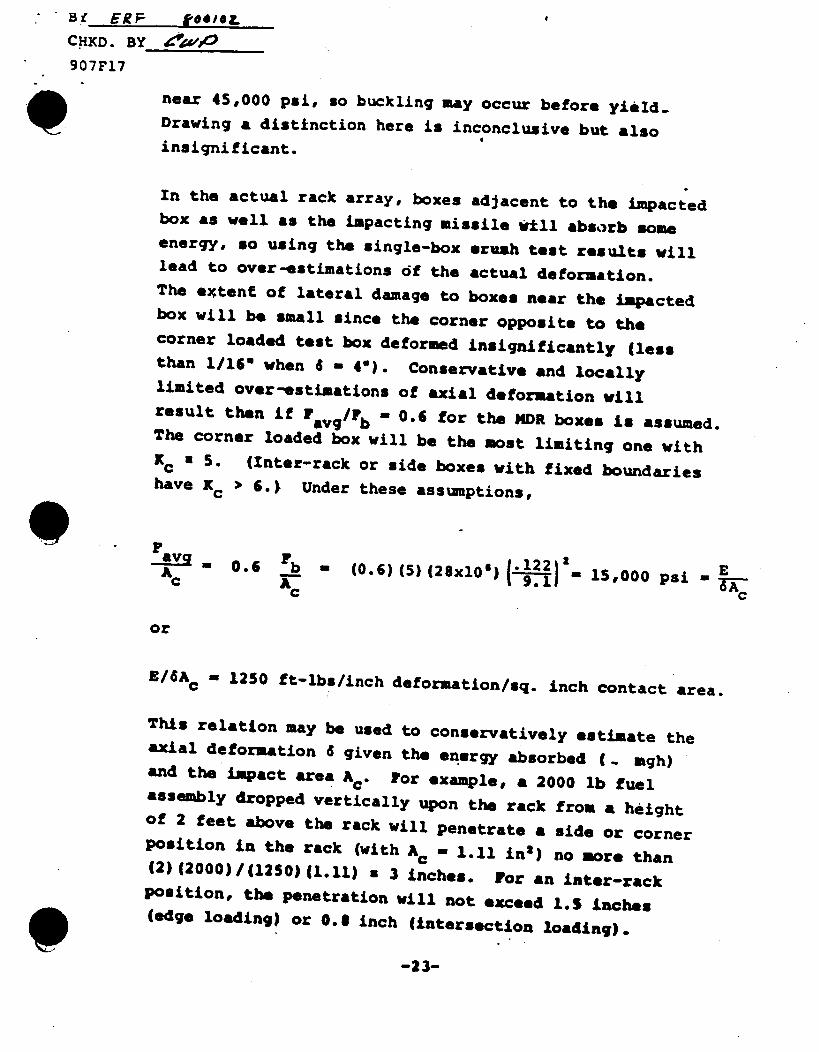
Bf ERF todIOL #
CHXD. BY i- , 4't
907F17
near 45,000 psi, so buckling may occur before yield. Drawing a distinction here is inconclusive but also insignificant.
In the actual rack array, boxes adjacent to the impacted box as well as the impacting missile will absorb some energy, so using the single-box ecush test results will lead to over-estimations of the actual deformation. The extent of lateral damage to boxes near the impacted box will be small since the corner opposite to the corner loaded test box deformed insignificantly (less than 1/16* when 6 - 4e). Conservative and locally limited over-estimations of axial deformation will result then if F avg/F b - 0.6 for the MDR boxes is assumed. The corner loaded box will be the most limiting one with Kc a 5. (Inter-rack or side boxes with fixed boundaries have K€ > 6.) Under these assumptions,
9 av 0.6 Fb - (0.6) (5) (2 8xO 6) (.1221 15000 psi . E c Ac
c
or
E/6A - 1250 ft-lbs/inch deformation/sq. inch contact area.
This relation may be used to conservatively estimate the axial deformation 6 given the energy absorbed (- mgh) and the impact area Ac . For example, a 2000 lb fuel assembly dropped vertically upon the rack from a height of 2 feet above the rack will penetrate a side or corner position in the rack (with Ac - 1.11 in 2 ) no more than (2) (2000)/(1250) (1.11) a 3 inches. For an inter-rack Position, the penetration will not exceed l.S inches (edge loading) or 0. inch (intersection loading).
-23-
•CHKD. BY- e.w 907F17 REFERENCES
1. Den Hartog, J.P., Advanced Strength of Materials, McGraw Hill, New York, 1952, pp. 245-250, 301-305.
2. Faupel, Joseph H., Engineering Design, John Wiley and Sons, New York, 1964, pp. 542-546, 509-511.
3. Shanley, F.R., Strength of Materials, McGraw-Hill, New York, 1957, pp. 608-612.
4. Roark, R.J., Formulas for Stress and Strain, McGrawHill, New York, 1965, pp. 260-261, 278-279.
-24-
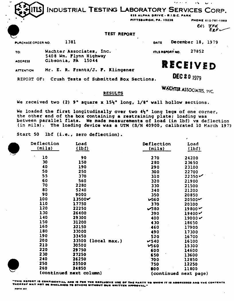
-. -. I I # .. I ,
INDUSTRIAL TESTING LABORATORY SERVICES CORP. 611 ALPHA OIIVft - NI... PARK PITTSBURGH. PA. 13l34 PH1 ON 412-791-1060
C',; 7FK
TEST REPORT
PURCNASE OROER
TO:
AOCRESS
ATTENTION
NO. 1381 OATE December 18, 1979
Wachter Associates, Inc. 5408 Win. Flynn Highway Gibsonia, PA 15044
Mr. E. R. Frantz/J. F. Klingener
REPORT OF: Crush Tests of Submitted Box Sections.
RESULTS
ITLS EPORT NO. 27852
RECEIVED DEC 2 o 1979
WCITEa ASSOCIATES, !4NC
We received two (2) 9" square x 15h" long, 1/8" wall hollow sections.
We loaded the first longitudinally over two 4 " long legs of one corner, the other end of the box containing a restraining plate; loading was between parallel flats. We made measurements of load (in lbf) vs deflection (in mils). The loading device was a UTM (S/N 40900, calibrated 10 March 1979
Start 50 lbf (i.e., zero deflection).
Deflection (mi is)
10 30 40 50 55 60 70 80 90
100 110 120 130 140 150 160 180 190 200 210 220 230 240 250 260 (continued
Load (lbf)
90 150 190 250 370 560
2280 5240 9000
13500wo 17750 22250 26400 29300 31200 32150 33000 33450 33500 (local max.) 30500 29750 27250 26250 25500 24850
next column)
Deflection (mils)
270 280 290 300 310 320 330 340 350
w360 370
w'380 390 400 430 460 490 520
w540 V560
600 650 700 750 Boo (continued
Load (lbf)
24200 23650 23100 22700 22350&" 21900 21500 21200 20850 20500w 20100 19800W 19400v' 19000 %e 18650 17900 17300 16700 16100 15300 14600 13600 12850 12250 11800
next page)
'Tr19 li UPORT IS CONPIjsTgaI AmIII pea tYiN gACLWUSVG U941 OF TNG PARTY TO W OW IT 10 A600611990 AND TNZ CONTUNTS T9NEOIP MAT NOT 94 0ISCL616 mTO OTNIIIIII WITWOUT OU* eWeITT9011 AlPOOVAi.*
*..u Sl
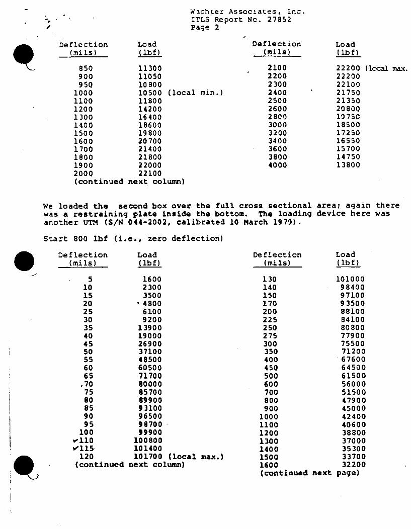
W:ichter Assocl.ates, Inc. ITLS Report Nc. 27852 Page 2
Deflection (:nils)
850 900 950
1000 1100 1200 1300 1400 1500 1600 1700 1800 1900 2000 (continued
Load (ibf).
11300 11050 10800 10500 (local min.) 11800 14200 16400 18600 19800 20700 21400 21800 22000 22100
next column)
Deflection (mils)
2100 2200 2300 2400 2500 2600 2800 3000 3200 3400 3600 3800 4000
Load (lbf)
22200 22200 22100 21750 21350 20800 1975C 18500 17250 16550 15700 14750 13800
(,local max.
We loaded the second box over the full cross sectional area; again there was a restraining plate inside the bottom. The loading device here was another UTM (S/N 044-2002, calibrated 10 March 1979).
Start 800 lbf (i.e., zero deflection)
Deflection (mi Is)
Load (lbf)
5 1600 10 2300 15 3500 20 ' 4800 25 6100 30 9200 35 13900 40 19000 45 26900 50 37100 55 48500 60 60500 65 71700 ,70 80000 75 85700 80 89900 85 93100 90 96500 95 99700
100 99900 W110 100800 e1ls 101400 120 101700 (local max.) (continued next column)
Deflection (mils)
130 140 150 170 200 225 250 275 300 350 400 450 500 600 700 800 900
1000 1100 1200 1300 1400 1500 1600 (continued next
Load (lbf)
101000 98400 97100 93500 88100 84100 80800 77900 75500 71200 67600 64500 61500 56000 51500 47900 45000 42400 40600 38800 37000 35300 33700 32200
page)
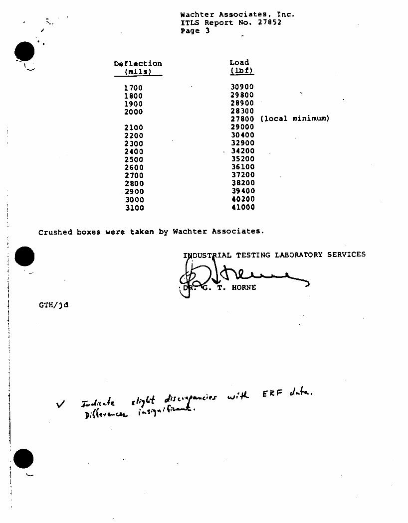
Wachter Associates, Inc. ITLS Report No. 27852 Page 3
Deflection (mi 15)
1700 1800 1900 2000
2100 2200 2300 2400 2500 2600 2700 2800
.2900 3000 3100
Load (lbf)
30900 29800 28900 28300 27800 29000 30400 32900 34200 35200 36100 37200 38200 39400 40200 41000
(local minimum)
Crushed boxes were taken by Wachter Associates.
TESTING LABORATORY SERVICES
HORNE
GTH/jd
'dJ t$- EX : J,, .•v j.d; .C 1g.-li
Question V.1
Describe the sequence for the proposed modifications and fuel assembly storage arrangements. If this results in a partial loading of a rack or series of racks, then demonstrate the seismic adequacy for this arrangement in terms of stability of the rack(s).
Response to Question V.1
Described below is the proposed installation sequence for the new maximum density racks. During several steps when the existing racks are partially loaded and may not represent a seismically stable configuration, temporary seismic restraints will be installed. Revisions to the proposed installation during the actual installation may be necessary. However, at this time, the following is the Authority's planned installation/removal sequence.
INDIAN POINT 3 SPENT FUEL STORAGE RACKS RACK HANDLING AND INSTALLATION INSTRUCTIONS
1. The maximum density spent fuel storage racks are to be installed in sequence with removal of the existing racks as delineated in these installation instructions. Figure 1 shows the existing rack array and stored fuel arrangement. Figure 2 through 23 shows the sequence of existing rack removal, UST&D rack installation and fuel movement.
2. Remove existing racks in this sequence, A-4, A-3, A-1, A-2 and A-5. See Figure 2. Install temporary seismic restraints on Racks A-7 and B-3.
3. Install UST&D Rack #1, locating it from the North and East wall. However, in the North-South direction the rack must line-up with the crane rails. See Figure 3.
4. Install the two floor plate combinations (See Figure 3), Group 1 and 2, from the South face of Rack #1 and from the East wall if the East wall lines up with the crane rails. If the wall and rails do not line up, compensation must be made for the difference. The racks must be lined up with the crane rails.
5. Move fuel from Rack A-6 to Rack #1 as shown on Figure 4.
6. Remove Rack A-6. See Figure 5.
7. Install UST&D Rack #2 in contact with Rack #1 at the bottom spacer blocks and the same distance from the East wall as Rack #1. However, the East face of Rack #2 must line up with the East face of Rack #1. See Figure 6.
8. Move fuel from Rack A-7 to UST&D Rack #1 as shown on Figure 7.
9. Remove temporary seismic restraints on Rack A-7 and remove the rack. See Figure 8.
Response to V.1 (Continued)
10. Install UST&D Rack #3 in contact with Rack #2 at the bottom spacer blocks and the same distance from the East wall as Rack #2. However, the East face of Rack #3 must line up with the East face of Racks #1 and #2. See Figure 9.
11. Install the two floor plate combinations (See Figure 9), (Group 3 and 4), located from Rack #3 and the East wall. If the wall and the crane rails do not line up, compensation must be made for the difference.
12. Install UST&D Rack #4 in contact with Rack #3 at the bottom spacer blocks and located from the East wall. See Figure 10. If the wall and crane rails do not line up, compensation must be made for the difference.
13. Move fuel from Racks B-1, B-2 and B-3 to Racks #1, #2, #3 and #4 as shown on Figure 11.
14. Install Rack #6 in contact with Rack #3 at the bottom spacer blocks and in contact with the cell in the last row on the West face of Rack #4, as shown on Figure 12.
15. Install the two floor plate combinations, Group 6 and 7, located as shown from Rack #4 and #6. Install the single floor plate combination, Group 5, located as shown from Rack #2 and #6. See Figure 12.
16. Install Rack #5 in contact with Rack #2 at the bottom spacer blocks and in contact with Rack #6. See Figure 13.
17. Move fuel from Racks B-1, B-2 and B-3 to Racks #1, #2, #3 and #5 as shown on Figure 14.
18. Install temporary seismic restraints on Racks B-4 and B-S and remove seismic restraints on B-3.
19. Remove racks B-1, B-2 and B-3. See Figure 15.
20. Install Rack #7 in contact with Racks #4 and #6, as shown on Figure 16.
21. Move fuel from Racks B-4 and B-S to Racks #3, #4 and #6 as shown on Figure 17.
22. Remove temporary seismic restraints from Rack B-4 and B-5 and remove racks. See Figure 18.
23. Install two floor plate combinations, Group 6 and Group 10, located as shown from Rack #7. Install the single floor plate Group 9, located as shown from Rack #6 and #7. See Figure 19.
Response to Question V.1 (Continued)
24. Install Rack #9 in contact with Rack #6 and the cell in last row on the West face of Rack #7 as shown on Figure 20. Install Rack #10 in contact with Rack #7 and #9, as shown on Figure 20.
25. Install two floor plate combinations, Group 8 and Group 11 as shown, located from Rack #5 and #9. See Figure 20.
26. Install Rack #8 in contact with Rack #5 and #9. See Figure 21.
27. Install two floor plate combinations, Group 12 and 13 as shown, located from Racks #8 and #9. See Figure 22.
28. Install Rack #12 in contact with Rack #9 and the cell in the last row on the West face of Rack #10 as shown on Figure 23. Install Rack #11 in contact with Rack #8 and #12 as also shown on Figure 23.
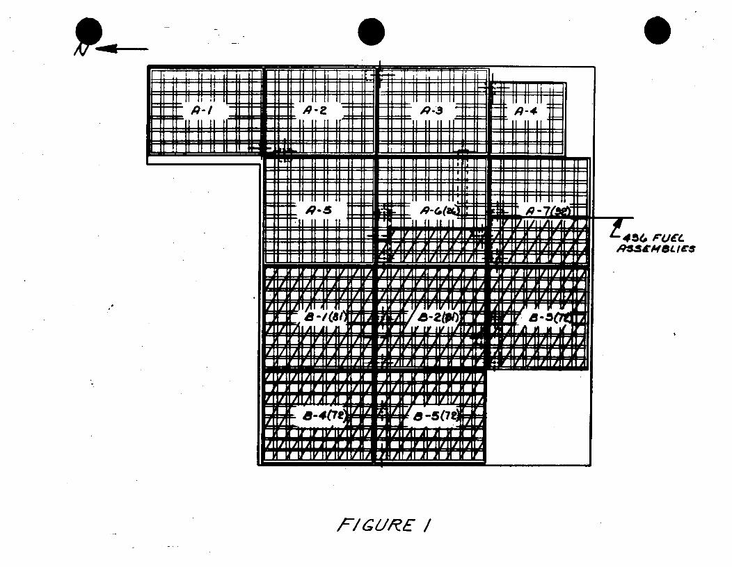
Eli _______________ U ___________________ 1= l~E~ ____________
V li ii if
'Q-s II II II
II II II L
/11 II II I
II fl I I II II ~ll~-E ~1~1 ~:1I11 11 I
ii i i i i iiiii* iiii II U ~ I i~ ~~~~~~~~f ii111 i i ii i i1i !
S2 K U C
it II II Ii #91- a -i
S"Af 8. cs
F/t4194YE /
1ii Ii I4 1
,-I ,' : = ,49-3 - :1-ii I II II i II II !!
. .. .. .. . .. I . . . . . . . .
_vIfl
/7--am-II II l1,l ,! il ,I Ii
II II II II
I1 II I I 11 1
11 11 ¥ II/I II/ I AI L
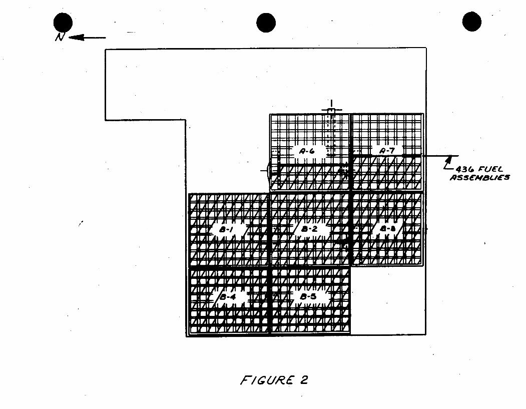
Al v
U-jl.,ilf
II II II
II II II
I~E~~3AN u IF17 I
E11Illl Al I
wwww~.qqj~rn! ~I I
=7= - '.7 .
-jmtm-,EMA-lA 'AFIAFI~w AW1Y'I
iAlli nlAill A AI.F 1 11Y
S.
i -7r:4iRW7 -
434 I 'J(L 3QS&C$t/E
FIGURE 2
lib
----------------1/11/1111/11
11 11 rl 14 I/ 111F
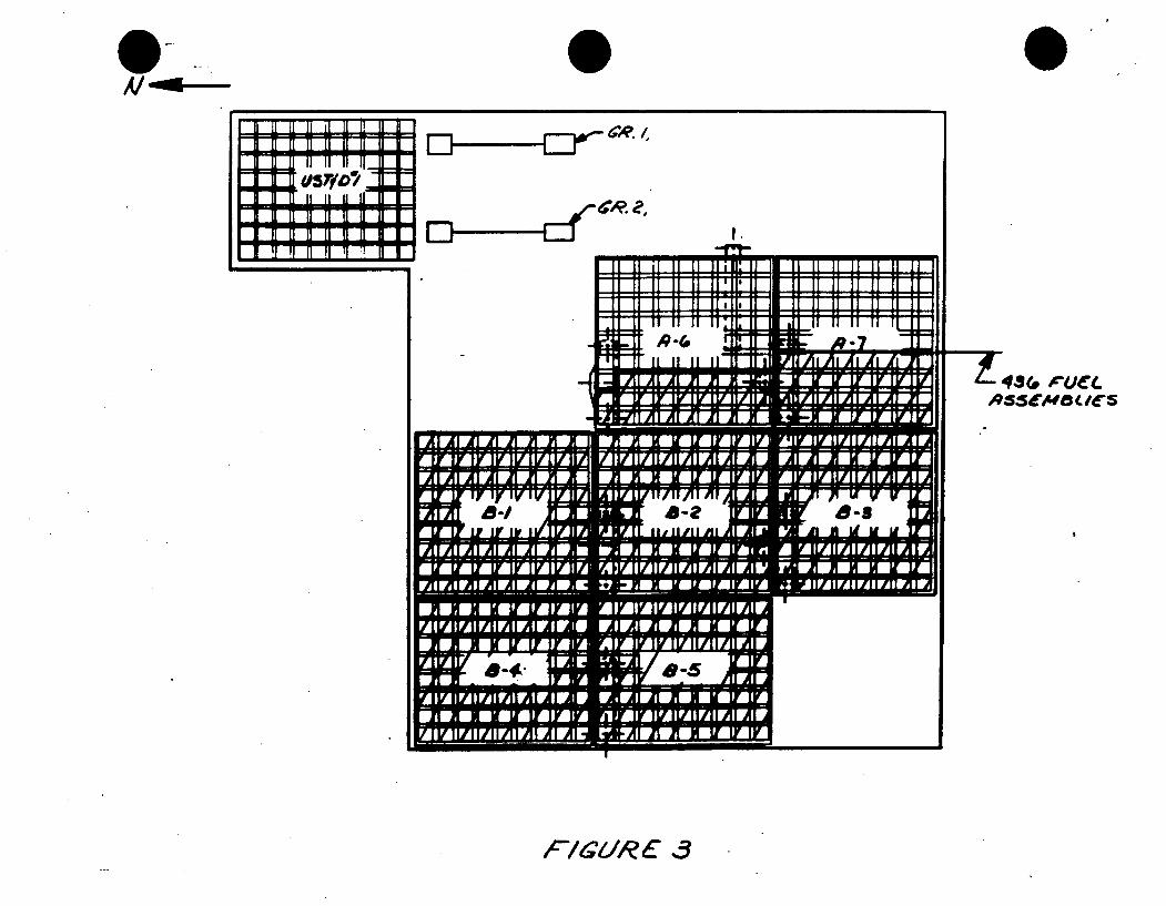
11 1 1 l 11U a
fi lS 1 11 1 1 1
H EE
11111 EI-- Zr-4dI .
* U
liiiII II II
SII II II II~
12 1 In i I I I I I II II II
I II lI3/14A1/II Al Al At
~~NflhiIIf Ir
114141 Ir ly IV I W v v
494 A-2 0-8 1 A
TAI A Al AM 38%*,d 11 'n A IL IF ly
t 3( ' #4r( ASSC a/cs
,C'/ 9IR E .3
.LL-U-LL-L RlROnlALAJ-A"L-, M'MIMIAIAI'AIFAl U HH
A1-dd&---
I 411 A(1 41 In II orl *IV I
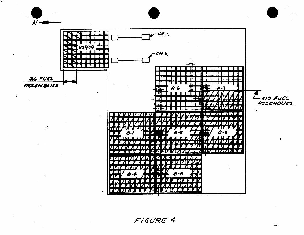
a& ra re _ mft RZScEM8ewJs I-
U51Y0 ~ SEf
1
K l-4
UyI VIz
fl t!U
II IIII II
M"M'MIMPAPAFlI
410 ft.VE.
... ... ..
/GURE 4
r i
I .. --fwt-
1
I ill il AI AI , I at iI in m
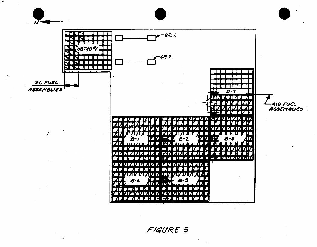
*( tI t. I EJ-d-
F/a'R6 5
-T410 dr(lec
IIf
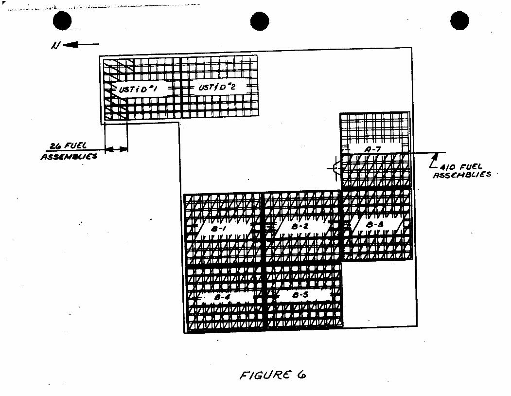
A/ W-
Zep ACMW
,S CN BLS
IV I-V I
•w .lv ly , -
Co
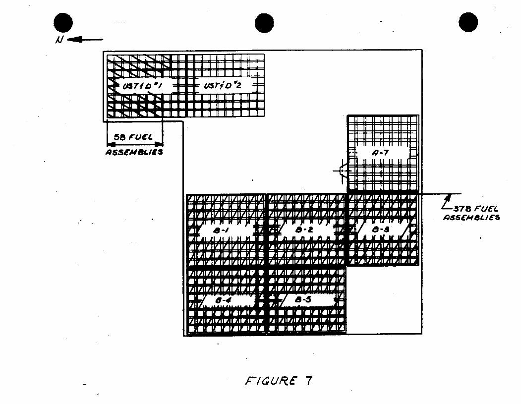
ti
A SS (N 8k/f S
HITUW IMIIIA-7 IA A 8-I AI -I
8-4 8-5
F/URE 7
Al ~
378 FUCL.
ff'*-4
Mrio 10/ 4z ri D ".2
11 H H H I a
, 1 9 1 1 1 1
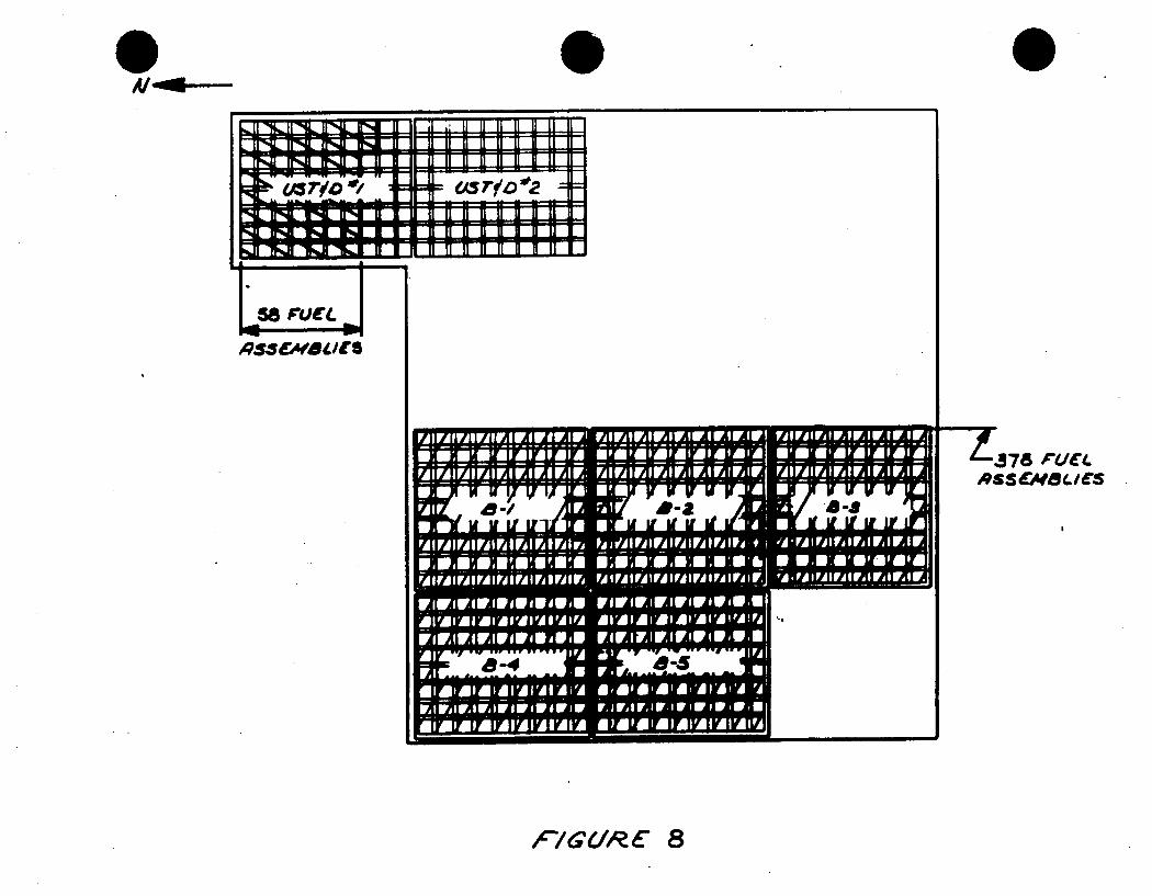
jQSS(M8S/E
/7GL/R a
UiQSS(AVBLA(IFAlfAlFJlFJlFjlVlWlFAW fjllFjlFlWAFAWlWlFlW
C i Fr -------------
WIN*, wa mAqm vr4'A.
FA I FA I IFA I FA I A I rA I ri I iri I Iri
FA I I eA I rA I F-A 1 r-A 1 rA I ri I FA IFA I FA I U I FA I FA I FA I IFA I rA I F,
wirlw1worowdogwo lF#wlwlwAwlwfwOW-w
41F'A'lAlAl'Al'Jl"AllAlFA Al'AlAlAlAl'Al'AlfA!Fj
ALL ALLI
r-- fir 1 -9 Aw 1w rAFAr'Ilr.lw IV or IN'S AIA' 1A lAiAlAlAlAlA M)AFMIAlAllAl'Al'AlFA
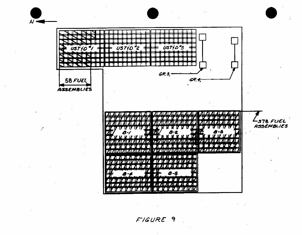
Al -0*
KJ FA on ON/C
AMENSLU(S
.58F/CAL .41SEMBL /S
.3'
4arro of as rib "1z
4- H11114 rQ r"*4- IL
1.3 _710 -S',HZLL 9 u H U
MIFAIM 1w Ivor twir A i Ii I i i li i I -A* 1'-A, 011111041111110MOMPAPAPAPAIA 0 1 ip' i I i 6i 14
E e I ii I i, I i I Fr, I Fr. I Fr,:,FAF. FA I FA I yj I FA I FA I M I r, I F I IF ri I VA I ri I F, I F, I W I IF I w IAI 61 11111141110 1A MP 0 I IF; Flo: iri TINOMF
OFMISWSPOPM141 Piro@ OWN, SP 8,1111,01111 0 WNIMP111110111111411111A YA-MrAlIF111FAIRAINFAW,
101W Irivilrowiff grip flVIFIVAriwirswill All
MIAPAPAPAPAPAPAI N)MOMIM04111A A U Fd,
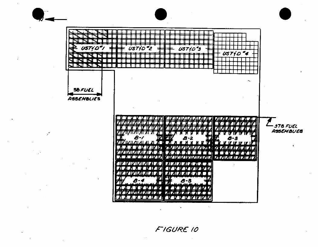
I -, . . , il ii . 1 H 4 li i 11 F ~. d Ll 11 ILI ,+- I! J .iJ.i! !!
LiW- "rloo=
II II II If II II II
-m H t ; N H I IH I"n I 1: -" 1 M ---- I I i Ir l 7/sjo 'v
44P4CAu 1
- &S 7' '3
M..lL..IA II II II II II II H
I I I I lI I
c7 fo"4 -
P/GURC /0
--. 778 Fu AMssetrsa
I ,
ir ly-fv-lvl -11,A] A] A] A lAl A
49-1 9 if ly ly I
Al
Al Al
IV IV invi
PLJI A lair Illyly!j IF IF I- IV IV IV
i
"N I"Wi - m m II 1I l1 II il 1I 1I l
I IF ,JI I BIP , I ! i .i || II II II II II HI II II II II II II II I
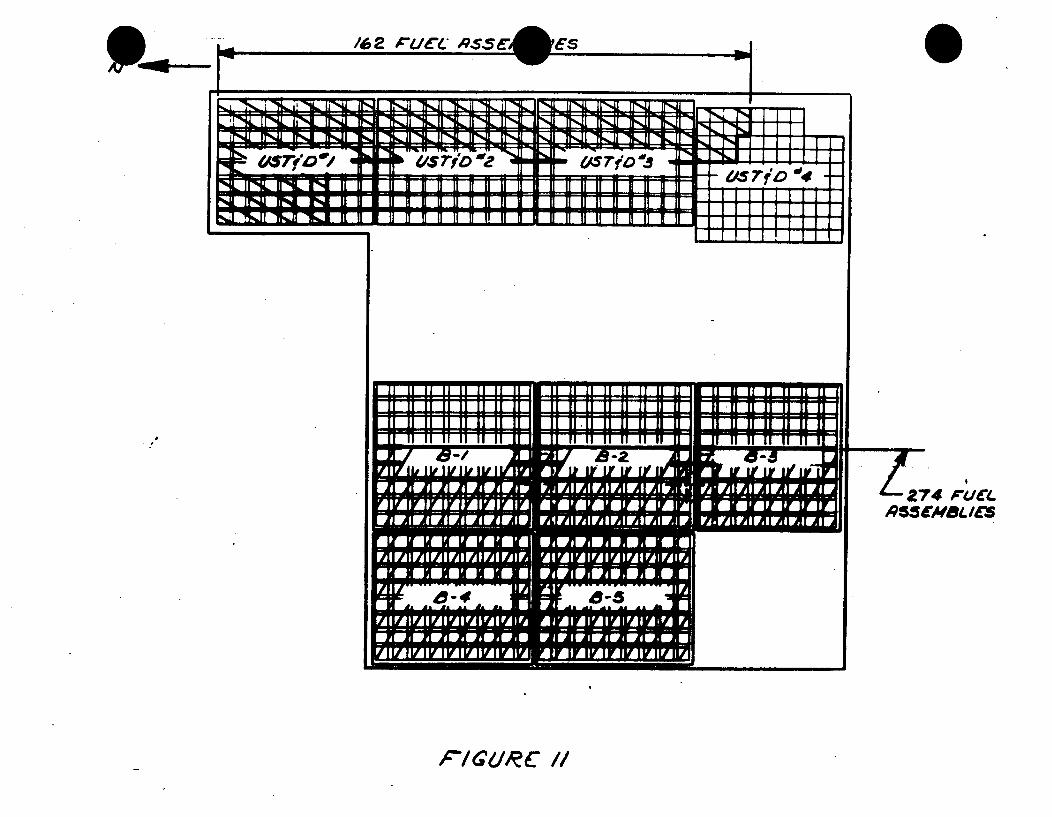
/62 #C~/CL 9SS (
___ __ ___ __ __ 1 !I!I,-,; I I I I I I I1
" 274 ,UCl. . $5(MBL /(r'
FIGUkRC //
ES- j
11J Z IL st lE l.U~U il1 bR-1 Q S" . - . I I I
=. . 1 :7 = =: : = == = - - s
r*4L ffNL P-4 ml-z
I
iF iFNL ir,-.a %-,,1I '% 11 1"1 41 If-% I?",,Jl II',,,Ji 11 Ji
w " elS rj4O Z - 445 7 0 "Sqqt "re104111 +1 11,1141 II,14L " II II g II II fl II II II II II II li II g
eAS 7l 1 i04
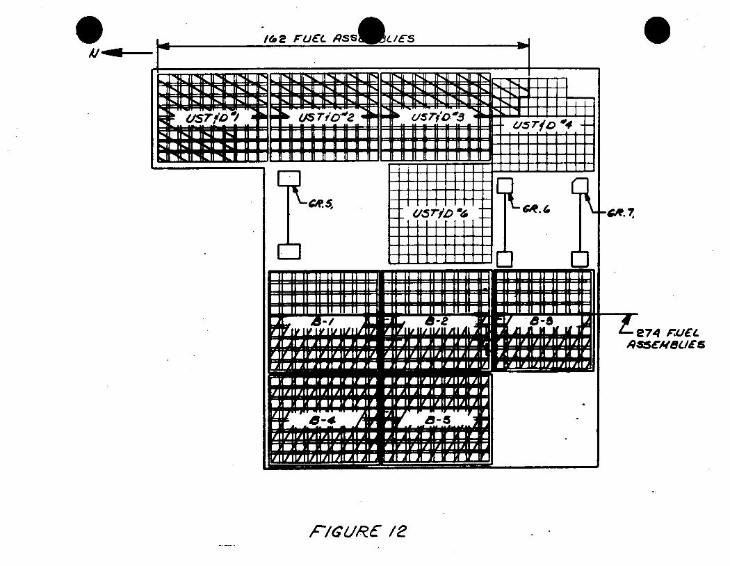
Ai -0
996.(. F.JC PSS uc- 5
Z _-. I 1 1l l
-e74 ,,UCt ,45SCROS/./
PIGUkC 12
I
11 If If 11 1 If 11 11 11 11 In-JLL .Ii 11 if 1111
jag
L141
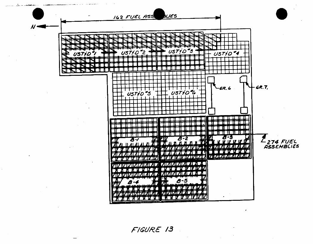
- 274 r~d'(jqssemsele/
F/16k( 13
Al -
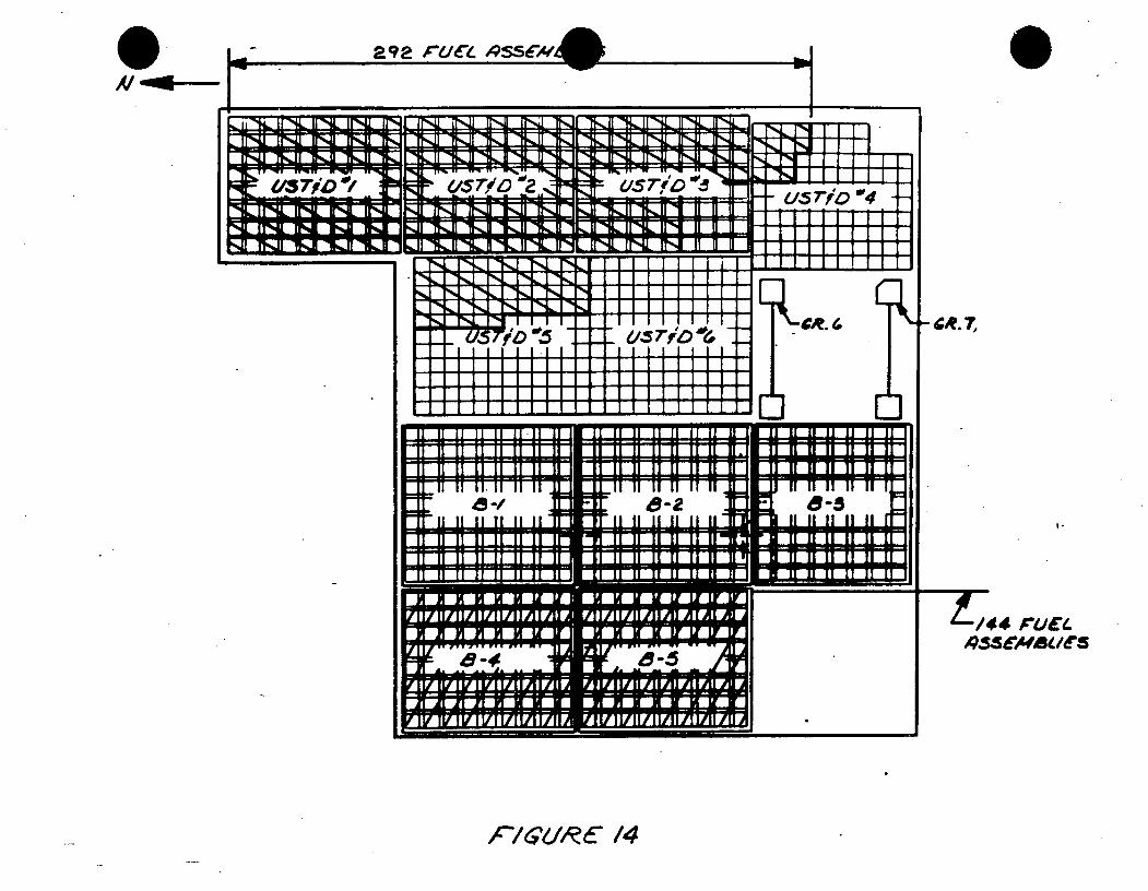
"M*-
2 9 P- A"UC. ,5SCA
fr,,I 1AI N 1%11i
/5Tjr /
ITR*A 11 .1 M%,m MNbI
'115 iTirL RL f9TImrT H f~a II ' , i I . .I! -%,.. I L ]UL il'Il iII IN,,Jl
- .. .- U - -. .. .. - U~II--1
~'si/o"a ~H k"IN JI T,,. "1*- .11 '%-H
i -hlLL I I I I1 I IuL 0io'4 -
tEWThIFelk. e*
B-28
II~ IL
(t i.D~E~OqJ I ~I) 'ii I~F.F.~JI
I- -
I.
p744 CL/EL QSSEAVBU(S
cFi4RE 14
I!
I
-7 -7
iI
• ' as rib c
-J -7 - Z- - 77-
!
l l l .L 1 11 1 II U
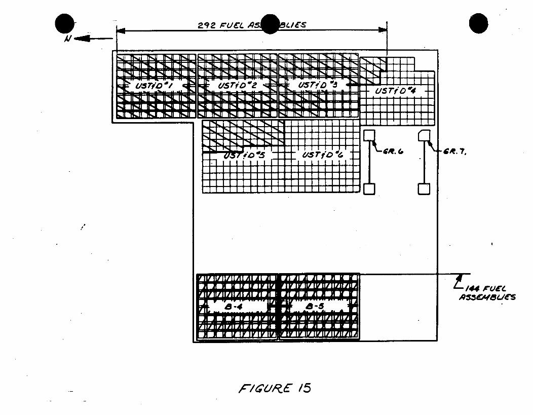
292 ,r/J(l.
irdl I 1" I1" ,l I WINNa r 1i.. .a1r:. .-.. .-.4~
U
U
I I, ,it - ,. EE
4 "'4. 7,
- - - I. I -
-~ 1-/4" rucle 19-"Ca l/e
,/ e "k /5
I
iQl IF.11 IFZ; lKil ITll "FrOl
r:: -
I' I ] I I I1
!
1 "%1 I I1 1 11 , I I -11I PL II" i, H "gk II 1 ; I -i II '1 11 -v 1,.I ,
II" 114if"% II l I% i
F"vroz;.
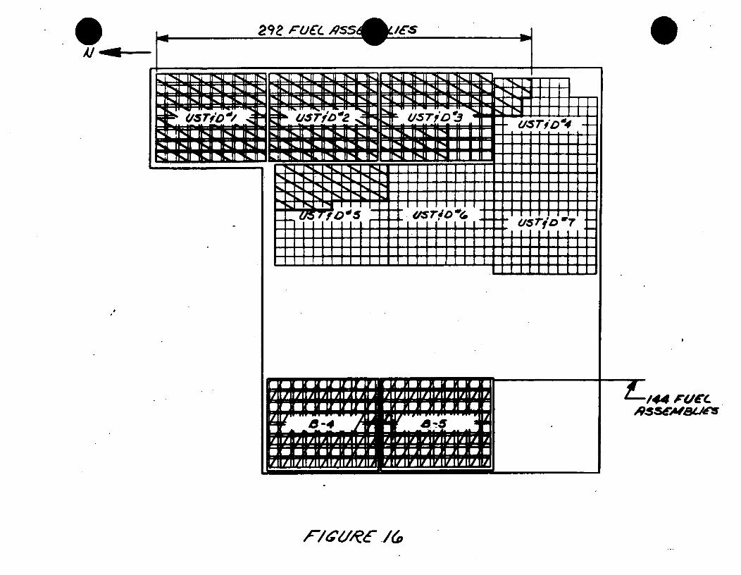
29Z rue As!
i~l TINJI N. U llI
,/cs
JWYK~{TZT1TTThRI-%nL IIN. gv4'R -N L -iAL iI4,L g"Ni. Lf%
7'jD'
=IqL~ & nb: I zrI m g ll ,.* m folim-- - - -- - WE
1 L IIFNL WlNl i.rN IqUI% ir%I If MT -r-f -,f -,H-%
N If I U' i11I'
I 4 .- I
I T D'04
Ie f II N f I , K
FIVIVIV1IVIVIR 11
9.-# m MU6c
Al -d*i
TFhCfNill I III
4 r.aI m
-i irla ir"41 lrIW4l~ i ' NI, '',
,,,J~r',,,Lr",,,LlS ij i 0 iiI l
FA I rA I FA I FA I FA I FA I FA I FA I P
'- W7:
i lk Ii 'I,. Ii 1 II •
m
--X-lao(IRC AA
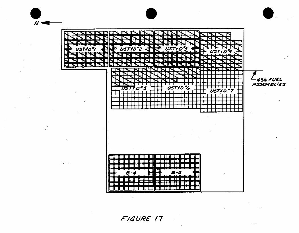
-%j Ma nl Ki 1~ll m1 -I ~ ~ ; >.I N.[J~
qp" /i?ii "+SI1"S F-~N
-- ii ~r ~
114 r - -IN- I %Vl 4..& 1 U . -
111111!! 111111 1.11 lilA 1111!! ifA!-4 a.5
-. - *I I~=
1 436 F41(L As5cM8~le
.............................. EL
FIS URC /7
Al -a*-
Fl%" IMM ml%.l M.-MIM m L-- -- -
lqqzr TL FIL I 4CH 1% I r*4L I
i. i I I I I I I I i
EL.__.._olma
"I lr*.JI MI ,U IIk% ll -M . -M-ll n%,-g
1. -.r. ' -....IAS rjD *4 t 1 r, , - A
aN4 mI I I I rl U I I I
I" L 1 "N, I "l" t I'lL I" I'" I "N I 1", l- I %1 r% IP I
I
i .. .. i i
]
T!i rl R'm I --ts,
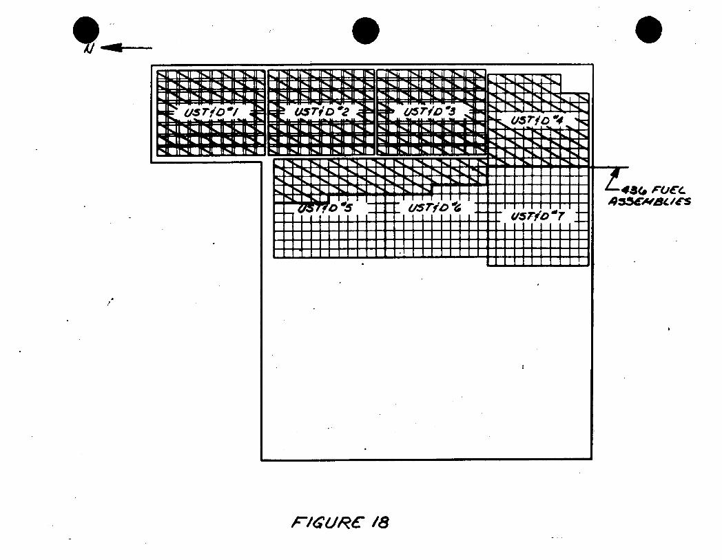
-~ * .- ~ r- ~e.u.u.umt.t.t.Imumt.uum.na
,-c7laUtRe? /8
1-4 'j UCZ.. 48(. PVBU1e
r .z T?.,H I -1 ,Jl 16111 INJI IS-1 J
Nj ['NL I -N,
US Tj D r &,S 7- 40
Im
-N L % I I I " ' l -.A I I I........ I
1 3 Il I I I JL L 11 1 1 1 .. . .
-" l I l l I III I# Il I I I I"
1 l l1l l ! 1 I i 1 1 ! 1 1
w -ad*-
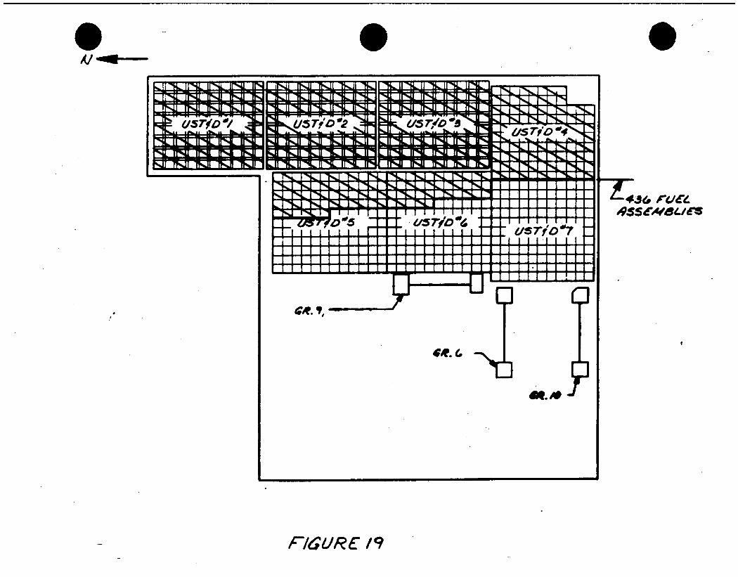
Al ,
=K usi rfo H57"l. -"N
_"U' 5 "'5 -, 7 1 I 14% 1 1*A I% 1 I i I I I I I II I I I I I I t
lilll ~~~41 ilj !iiil7 !ilI
CRA,
ER.6
f43 roa 09sevdales
F'6UR /9
t 1 ! 1 ] t I 11 r*L I L I % 1 71
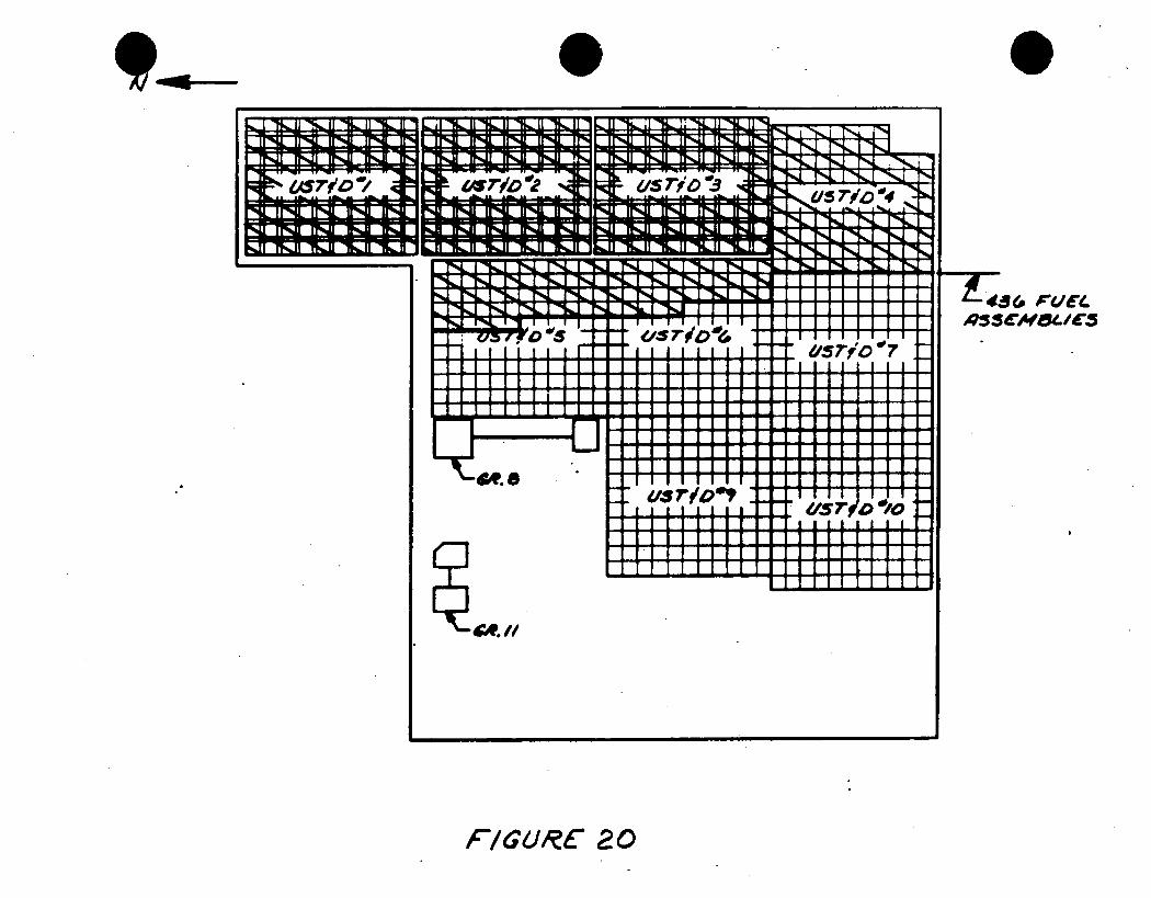
-. . . .- . . . . . . . . . .
%% I- I1 1 ' 4 l A&i r~CTI %~FI - - -. -. 1-9
IA I N*J i rN. I l I
5S '04 iiLF -1 ",n " " ri" i
t1 I y IIHu I -J~ ~ ~~~~~~I Ij III I-i " Ti"7
L-j.T i iJiL 1 1
!i!T III
!I II
± 43& $-/'e.
F/G&4RC 20
,,-l :j$'ll :$jl ah, 11 kil JlA ll -r L OL ILML M -111 N,"- wtltq " -m Tpq It! jDj irs" lps irNwt I I 'M.. 11 VD-11 To, 11 '71111 mw_ If TV-11 MIN 1%, 11 -M, 11 It- 11 F%- il nh- 11
i
l qkl i J f' qkJI
ll I i' b, LI r kll i I LII l i hmll li :
I I -?*.i r%4L 1 '1%, 1 rl%
w -No-
I
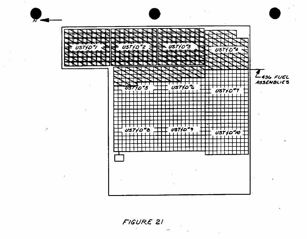
'w Iril IrM R~Jml
PhjI 1L I sl_ 11 %. II -~ii in i~:1 .. z iv; ... .* -4 ....
I,
QAO-IG Fl a Zu4jojoiaow zesi -~
.-
ZVI
U-S570 '2
1Ii~ W ~ L Wi~hJJ I1%II E~ flU fl~ U fl~ U I ~ -. - U
I-. -~ ~9.
.- %% F-4,1 'SO 7SlAd?
a rb08USTo
I I 1
- .
VST9O~ -
a
434 PC/CL ~95SdWBL 'CS
F/tR 6 o2/
11-4L T*4L INL- p - w -- w - F40
T%%L 1 -14%.l
god
I
r%41 lr*lx lr**,U frufl-*& 11-4, iI" !L.
r]j,,TJl 1,,,Jl
LIIr',, II%" 11I -,,1I1
I -..... ., 5 / oI II II IL III ]I H 11 111, 1 "11 .1 I II 4JI fl JI tJ
II ll IL ir' lu IlgWUR L II L II II l I
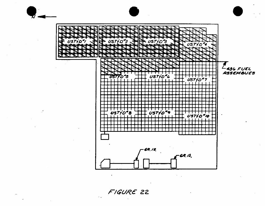
I I -iL U-111A- UNL 1-4 1rl4 Ir-41 TNJI
Um 25r:
T*--L rib 10.3
I 1% I P4 I % 1 7%.. 1 r.%.] I I m- ISI i I 1~ 6:u.m m Im Im .u
",Z"E = I- , -, -IL rI ' ll I I I I 11 • r.,_L 1-- t - I, I I I Il
T I I .,s ~~~U 7'" vs'." s¢°.
U5r/
486 I"UCL. AS!43M(0 /uC
. lrlOt-lKA -114LI
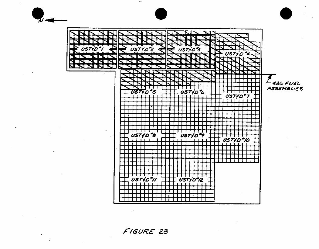
-/., a-
I T& if -4L 11 -1& it IL -4j Il- 11 --II II I
E. T4N IAL II I II 1L II 9% II 9 1. II 1L II IL II 9 II I
w . -
= &, 7jOL INll IINdJ IrN1 I1%
-~II r~ in' I ~ II~~ liii II~ U
Ii .. J NZ[ 1 5 Q I -*I NJ. [Ml I N- % i%I -~ I F~J I. I Lrl-Iq* ~. ~ ~...i r ~ -
"+,J ', r 'l -N I . II
"R II I! I I I I if I I f il
IAUr#' rio" us7~
I I: I I I I I I I I 0 i
f i l l 1 1 111 I.I 1 11I
__ 4io // "u r o /
I II
r/gURC 23
%.L" S L- T-Qi,
f43(, oLCLve ASSd-/4ur/
I -lp_ I
ir*-z lrz :
k -- . . -- ik ii . .. .. ,. . ., II l '" -. 1, . . .... II I II
:p , ,
I"% IIlil lrl r IULl irMi ll Ii- 1 U Ir1-0 r I'NJI 11 TV,- 11 M- 11 ll
415 Tf ,O ".21
! NIIIl "lJ ff%11"%% "INJl "it1 'WlJI '%-:
I -.%, r-L J- I A-I. 1 I-A
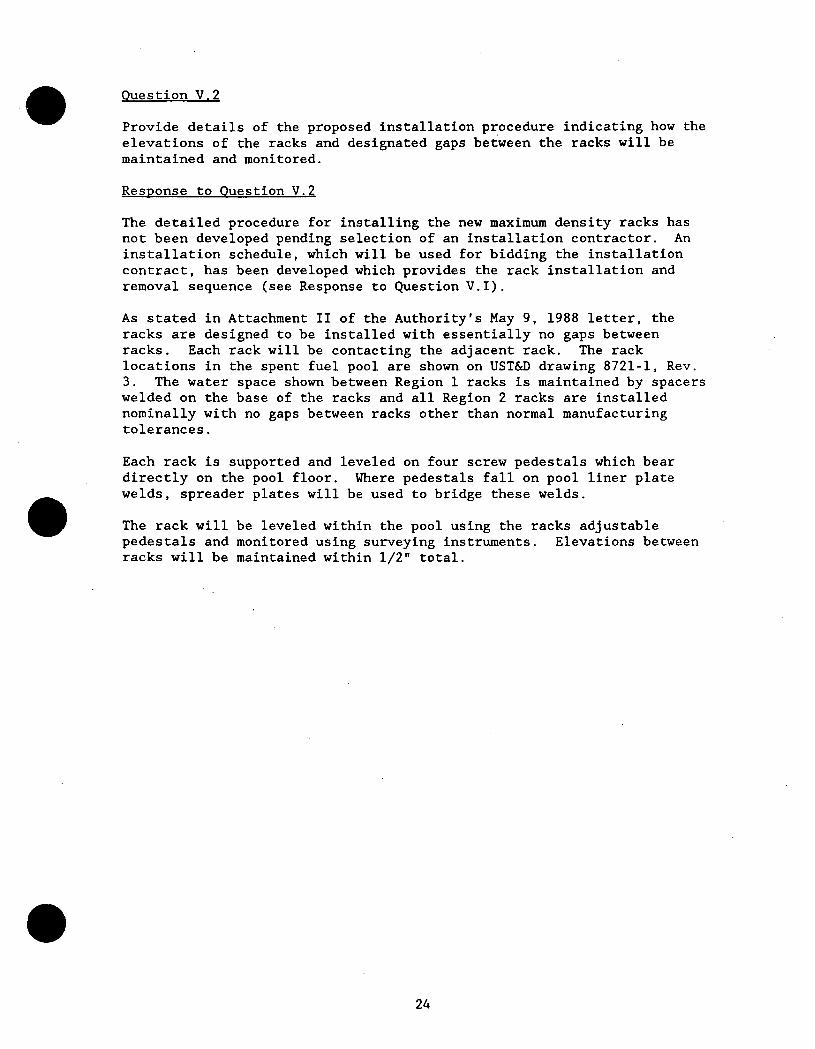
Question V.2
Provide details of the proposed installation procedure indicating how the elevations of the racks and designated gaps between the racks will be maintained and monitored.
Response to Question V.2
The detailed procedure for installing the new maximum density racks has not been developed pending selection of an installation contractor. An installation schedule, which will be used for bidding the installation contract, has been developed which provides the rack installation and removal sequence (see Response to Question V.1).
As stated in Attachment II of the Authority's May 9, 1988 letter, the racks are designed to be installed with essentially no gaps between racks. Each rack will be contacting the adjacent rack. The rack locations in the spent fuel pool are shown on UST&D drawing 8721-1, Rev. 3. The water space shown between Region 1 racks is maintained by spacers welded on the base of the racks and all Region 2 racks are installed nominally with no gaps between racks other than normal manufacturing tolerances.
Each rack is supported and leveled on four screw pedestals which bear directly on the pool floor. Where pedestals fall on pool liner plate welds, spreader plates will be used to bridge these welds.
The rack will be leveled within the pool using the racks adjustable pedestals and monitored using surveying instruments. Elevations between racks will be maintained within 1/2"' total.
Question V.3
Provide a description of plant safety procedures as related to the spent fuel pool in case of:
a. fuel drop accident b. a seismic event (OBE exceedance) C. loss of water from the pool detected by leak chases or by low
water level in the pool.
Response to Question V.3
a. Fuel drop accidents are covered under Site Procedure ONOP-RP-2 ("Irradiated Fuel Damage in Fuel Storage Building"). It
addresses the indications to the Control Room Operators that would immediately indicate any associated rise in radiation fields and the protective actions that would occur as a result of these alarms. It then addresses the subsequent actions that may need to be taken in order to minimize the air and water activity levels in the Fuel Storage Building. Finally, it specifies the circumstances to consider in the evaluation of the damaged fuel assembly.
b. The operation, startup and shutdown of the seismic monitoring equipment is covered under Site Procedure SOP-S-l ("Seismic Monitoring Equipment"). In the event of the occurrence of a seismic event exceeding the OBE, Site Procedure ONOP-S-l ("Seismic Monitoring Equipment Actuation") provides the, necessary operator response, depending upon the magnitude and
location of the seismic event. This may include bringing the reactor to hot shutdown. The condition of the fuel and Spent Fuel Pit is covered under:
it..after a detailed engineering survey of the plant
structures and components, an engineering task force will
either (1) recommend to the Superintendent of Power that the
plant can be returned to power, or (2) specify procedures and analytical work considered necessary before the plant can be returned to power."
C. Loss of water level in the Spent Fuel Pit is signaled in the Control Room by a pool water level alarm. This event is
treated the same as if it were a loss of water level in the Reactor Cavity during refueling operations. The associated plant procedure, ONOP-RP-3, addresses Procedure SOP-SFP-l ("Spent Fuel Pit Cooling and Purification System Operation") in
order to provide borated make-up to the Spent Fuel Pit using
various methods, e.g. through the Refueling Water Storage Tank or through the CVCS blender. Procedure SOP-SFP-l also covers operation of the leak detection system in the Spent Fuel Pit.
All ONOP's (Off-Normal Operating Procedures) address activation
of the Site Emergency Plan as appropriate for the events they cover.
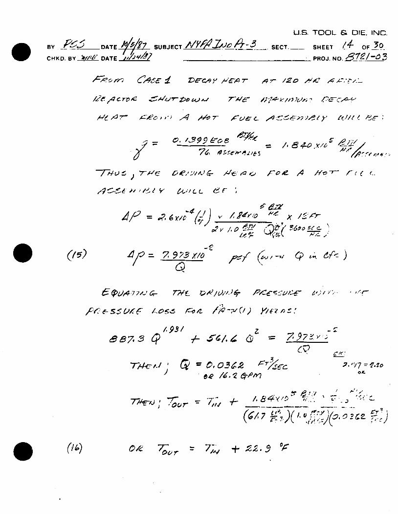
U.S. TOOL & DIE, INC.
.B / ' ATE 2 -,,i ',L SECT. O.SHEET .. 7 /
CH KD. BY '11/DATE 117 _______'______ PROJ.NO ____
Z&-C,4y v .'',Ll, 7-
,2g~4 ~~e ~i'U7~t A 4- -
I-
7WC /; ~ /4 ~ ~'
7e. /15 9. 6!_o
-7--11-) ) 7-,4'c C ., C,/-.sL- 4- , t r oe 1 A / -r- r- e C e
6'.'/ (.L.. F ',
,,x A,7/ f
<p t£4I 67r<)
7WL ~4)A'J#
f~&ssC~f.e LO~6 ,~
7. 3 L'? /
1I
74- -I -
7 -S6/. 4
6' 3 gT
~ L.
ale / 1 12 -,pfr
-7,1
(14) 70~,/ + - 0 6
/ p.'',-. ie~,-Y~,,A re.'.' ~ ~
(~~/7 ~)( '~ ~ ' ~A3e~2. 2
,4- 400 /111C .X-,bL-
4 1-16' ,0,- " / I s-,
4 p = 7 .9 ,_? x1o 0.
• . .'
2. ")7 = 17-90
04) 77 To
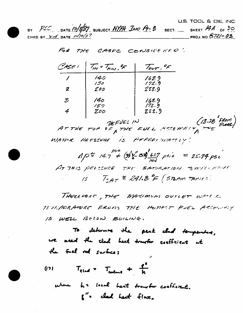
U.S. TOOL & DIE. INC.
BYf~. DATELj41/ SUBJECTA//) AIV2 SECT. __SHEET 144OF 3 CHKD. BY___ DATE _____ _ _ _ _ _ _ -7 PROJ. NO._7 _.
/o /5o % C L., )
1. 741 /T.
4717/ /4.z~7* 4,, 2179O
6%&44r. ~ 4~Mk
4L fet "i4 s.r4vcA:
I"~ ~aot 4uk 4 laqrg
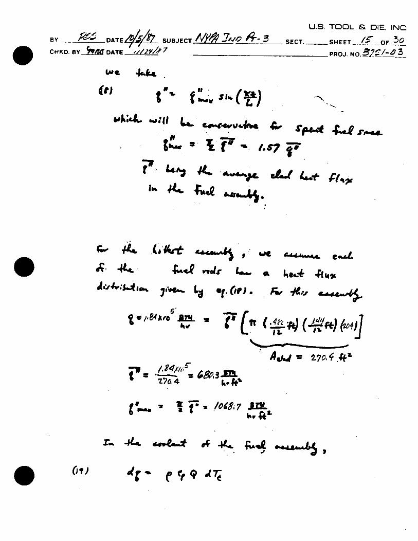
U.S. TOOL & DIE, INC.
By Y DATE4kZ SUBJECT /i4O-XO ."04- SECT. __SHE ET- OF 3 CHKD. BY M DATE ,'//2, 7 PROJ. NO. ,;__-"
LAt, 4..
(t) t ee hm~V
, 1,044WW agr7q P
OWN-n
. 4oa,44,t4~4h'4~C..4".,
/f 8 o . '
. 770.4
U
r., -td4
Wet C4A -d~. e"4
a 4e4.- A 14 L
AM h t
" Ai r '.., = IL70 44
k. 41.
v t-Fa.1M , L'
I 446 4 4. ,
(it,.
A v -9-1f
t w
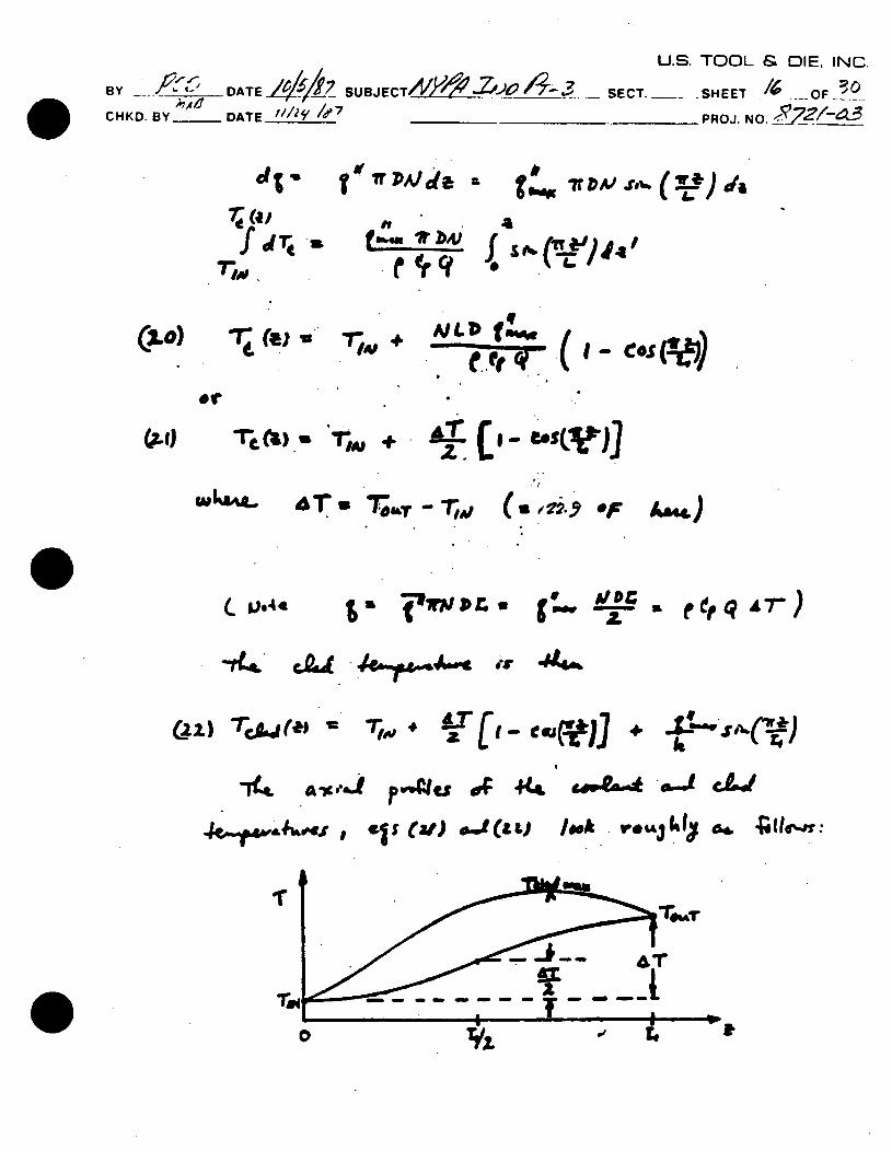
U.S. TOOL & DIE. INrC
BY~~~ ~~ 0_ A'- DATI ,i _UJC4~V SECT. __ -SHEET _
CHKD. BY_ DATE _/1121 /?7 PROJ. NO.
dt 'f" fWPAJ/A r # ir t
7(4J "f d "rm
e, Sto-o
+ fNLDf ter
SN
q
-~'.- (e~ c~ 11 ("
AT u TOO&, -T'
6s "I W sor.u * ro z -
e eq 4 )
~Qd4 A~4~c er 14f
(22) "TcA,,(*I =
cove.-A- wJ
,st).4(a l eok ,. ,jhj 64&
(2-o)
W604.
C. ve4a
A&.4
.'7---F
( u0 22'9 OF
+ Af"-W*.ro-,rr*) It rq
J~p.,. -ge , 4ts
A!:
AT1( - effiffl] 1.
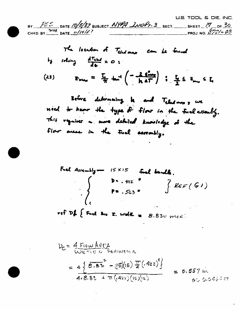
U.S. TOOL & DIE, INC.
BY ' DATE / SUBJECT .... 3 SECT. SHEET OF O CHKD. ,,___ DATE __ PR OJ. NO. _
do-%.g &4q
I' MAW L- 4. PIP? ' i
* v,.. iS, L 0 v c '.-a
,*f ~$(F1L 1q1 ?. Lm"SA " .%
~4 rLC~ 4'W
4 -z
=. v. 5E7 £~A~
~ ~c<~
7'e& to cehom. of
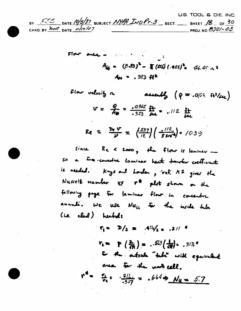
U.S. TOOL & DIE, INC.
BY DAT SUJCT40 A PI SECT. __-SHEET OF__
C HK D. B Y_ _ D AT E____ ____ _______ P ROJ. N__0
Fo,'-" ,~ - ..
At* IL~ fr
____ ___ * /1 S" ( .,_ q _ .._,
g. _ ¢. - .It_- :_ JIB (J Oz
fhtselt K #A v
I4- .ticftfhft
4%S IA ti
Pour .* k, r 4
4w 44 CC.-IL"
.4A 1,/, 2, / 4I
V" '& ft p .I_ . .) , , aq .. :, &AL" 4 44" 7 A
3 4
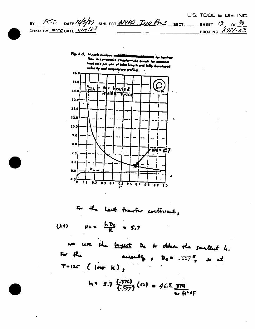
U.E Bv D DATE _ . 7-SU. JECT ,4V Y - SECT.-CHKD. BY _//. _ DATE _ __ ____ _7
SHEET OF
PROJ. NO. 3Z/d3
N . 6-s. Nui@ Ih .Wa4 W III flow In a gEWick-€ WIJ IM 6'o h1%00 pe wn" Of hake Ie09th ond Mlu , dsv.lopw
'eloeley WInd Iia hWW. Pwrilm. taft
rey 4t. LL* -4va'w~
".d44,4)
D
'be it ,'S57
IjU 8*~7 u 4(.2. IO
IA4 - N '
J, .
3. TOOL &. OIE. INC.
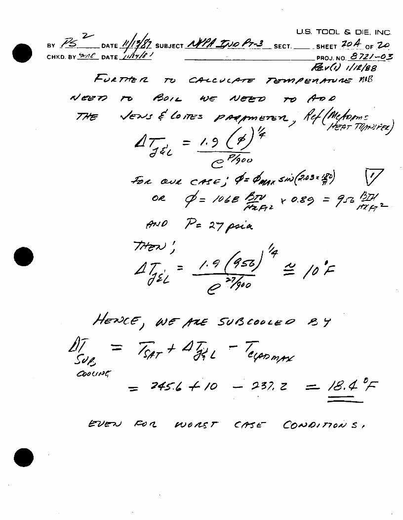
U.S. TOOL & DIE. INC.
BY DATE I A SUBJECT O,_ __7 ,- SECT.... , ._ .OF
CHKD. BY____e DATE___ ____________PROJ. NO. me2-0
oe. t.- 4tc- -vee 7-V e-V.
/17o'-X,- 127
e~-~-'~ C0
S( )
c& -1,999
- 0. cfpoe"a.r Z
,, --O -'
7~) / I
47-/e 9o 4e /4
4~9r~'K4L c~o £/~4~ ~
~- /6'4 ~-
clC);. &6 C0,004- r7A' s~~: "
774=,IOJF 7-
e7-ai -pt ;-,
0 4x e7r)
7 Z 7t / 2-
-57a 6 ev p 4
eve-A.) 4o rL AV 6 AX_ r-
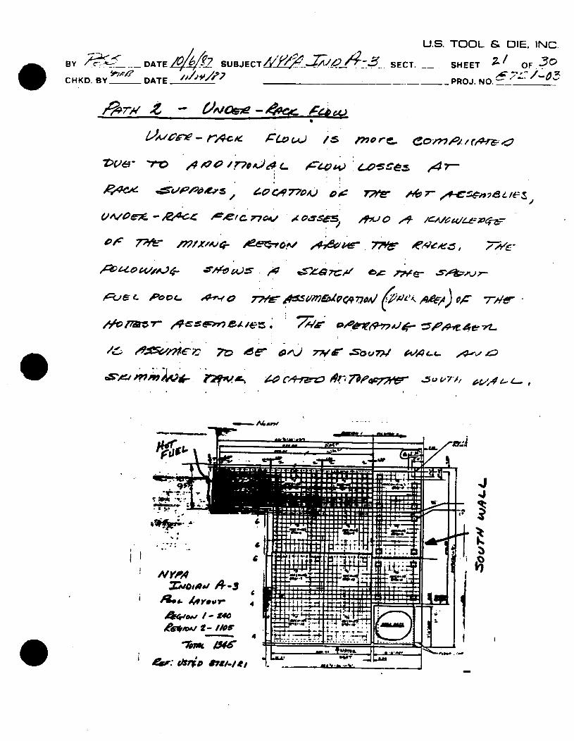
U.S. TOOL & DIE. INC. 44o P2 SUBJECT 2--2SECT. SHE / OF. , zz~SCT SHEET? O. -7
CHKD.BY- DATE PROJ.
cHKD B _ D A T CO MA_ -O_ _
Vve- o $4/77u.)~~c774 ~~e~e47
/4A/7aM 4 7OA o&"4"oj1 =' ,oVA7
_,Cr) 66 470 -1%) 77& ,9,LA 0 4e
lilt"
NYI'A - i
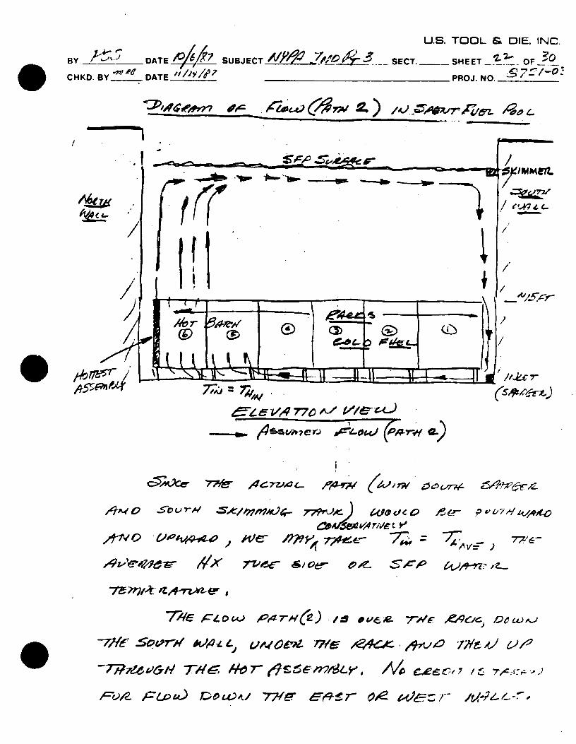
U.S. TOOL & DIE, INC.
Y____ DATE d0 SUBJECT____ SECT.-- SHEET OF
CHKD. BY_,___ DATE________ PROJ. NO. -7
II
,4 77
,q]A€ 0 -. ou 7-,," 7??/vtr/O~-; /J We@ <. 0 , .. ,,i-' 7-'! €
71 c'r A~~ 77- xeA/v'e 71-'wr *Ay . 54Dcc-a
"7 ;4,eo &1 4/ l 7 7L ,7 -TBZ~ H"T , Hz" n"/'z.v, _ ,., , ",:::-,.
lk'M:t~ '
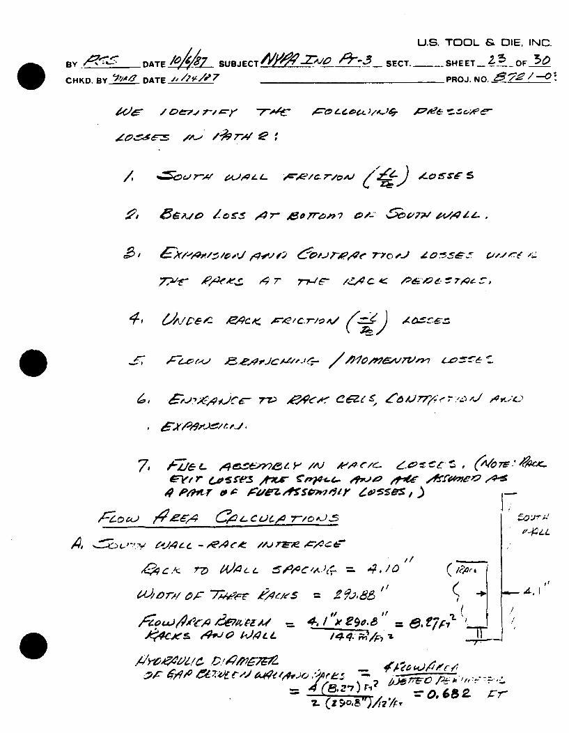
U.S. TOOL & DIE. INC.
BY -_______ DATE! ____ SUBJECT 4O,-Z '/A '0+--5- SECT.._- SHEET_!5_OF O
CHKD. BY____ DATE_______ PROJ. NO. , _______
c-- - o i Z72 TX ,. } e
K C/d2 , 0 4 ,q:v!,' a~T, 6:,J-Ap. "=c A) - P_0,,,,'./'., 4
,#. .- 4 7- 77-/ 1,4 C .-,
e le- to -z C I-. oFe ~ e ^.ci-s C=q; z.- Ofm St~ ljrae e4.
- /57~7)7.~? 1j 7 ,r 7~-/~~~
z.(z~o.~,477' ~O682 r7-
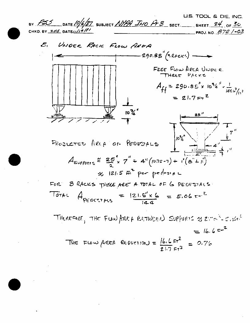
U.S. TOOL & DIE, INC.
BY. 142:,: r DATESBET T /% SECT.---- SHEET. 21. -OF-/ 3 C H KD. B Y D DAT E /I 9 '______________PROJ. NO. 8~ -
C *toq-b1
f - A I, pp -- le
-
'I .7 V
A v. p o r..- 0 ,PPL
'K
~Q(L. QA-L TD ,-7A-. L- P 6 f -11CA7
'To-r4-L 4 O~~t
14- d
olrr1 i Wq T r u u) /\-iv~fu ~ ) I ~ p & -r- it 0P A-)
-74E ~ ~ ~ ~ ~ ~ .~ PFTA)2
0Ue10 WLi-
,4 S u p PO Pr -s
= .6. 6 ( r --
=- 0, 7

PROP
PROPRIETARY INFORMATION
NOTICE
THE ATTACHED DOCUMENT MAY CONTAIN "PROPRIETARY INFORMATION" AND SHOULD BE HANDLED AS NRC "OFFICIAL USE ONLY" INFORMATION. IT SHOULD NOT BE DISCUSSED OR MADE AVAILABLE TO ANY PERSON NOT REQUIRING SUCH INFORMATION IN THE CONDUCT OF OFFICIAL BUSINESS AND'SHOULD BE STORED, TRANSFERRED, AND DISPOSED OF BY EACH RECIPIENT IN A MANNER WHICH WILL ASSURE THAT ITS CONTENTS ARE NOT MADE AVAILABLE TO UNAUTHORIZED PERSONS.
COPY NO.
DOCKET NO.
CONTROL NO.
REPORT NO.
REC'D W/LTR DTD.
PROPRIETARY INFORMATIONNRC Form 190 (4-78)