u-shaped slots loaded patch antenna with …jestec.taylors.edu.my/vol 13 issue 5 may...
TRANSCRIPT
Journal of Engineering Science and Technology Vol. 13, No. 5 (2018) 1396 - 1410 © School of Engineering, Taylor’s University
1396
U-SHAPED SLOTS LOADED PATCH ANTENNA WITH DEFECTED GROUND PLANE FOR MULTIBAND
MODERN COMMUNICATION SYSTEMS
K. G. JANGID1,*, P. K. JAIN2, NEELAM CHOUDHARY2, BRAJRAJ SHARMA3, V. K. SAXENA2, V. S. KULHAR1, D. BHATNAGAR2
1Department of Physics, Manipal University, 303007, Jaipur, India
2Microwave Lab, University of Rajasthan, 302004, Jaipur, India 3Department of Physics, SKITM & G, 302017, Jaipur, India
*Corresponding Author: [email protected]
Abstract
In this article, the design and performance of circular radiating patch element
with two U-shaped slots and defected ground plane, comprising of a triangular
notch monopole structure with rhomboid shape resonator, is reported. The
proposed multiband antenna has a compact structure design for GSM 1800
MHz, WLAN, WiMAX and UWB communication systems. The antenna is
designed on FR4 glass epoxy substrate of size 39 mm × 34 mm × 1.59 mm by
using computer simulation tool CST Microwave Studio 2014. For confirmation
of simulation results, prototypes are fabricated and their performance is tested
in free space. Measured results demonstrate that fabricated antenna provides
triple bands with impedance bandwidth of 157 MHz (1.733 GHz to 1.89 GHz),
3.2 GHz (2.29 GHz to 5.49 GHz) & 10.45 GHz (6.83 GHz to 17.28 GHz),
almost flat high gain between 4 to 6 dBi and good radiation patterns in the
desired frequency range. The maximum measured gain of proposed structure
is close to 6.59 dBi at 4.40 GHz. The circular polarization is also realized in
the frequency range 4.12 GHz to 5.20 GHz with axial impedance bandwidth
1.08 GHz. The specific absorption rate SAR values of proposed design are also
evaluated at various frequency spots which are well within the SAR values
specified by the FCC. Proposed design may be proved a useful structure for
advance radio communications systems as well as for the present requirements
in defence applications.
Keywords: Double U-shaped slots, Monopole structure, Multiband patch antenna,
Rhomboid shape resonator, Specific absorption rate, UWB
communication system, WLAN.

U-Shaped Slots Loaded Patch Antenna with Defected Ground Plane . . . . 1397
Journal of Engineering Science and Technology May 2018, Vol. 13(5)
Nomenclatures
fres Resonance frequency, GHz/MHz
h Height of substrate, mm
m Radial mode number
n Angular mode number
R Physical radius of the proposed design, mm
Re Effective radius of the proposed design, mm
S11 Reflection coefficient, dB
TM Transverse magnetic mode
Greek Symbols
eff Effective dielectric constant
r Relative permittivity
0 Speed of light in free space, m/s
'
mn nth zero root derivative of Bessel function of order m
Abbreviations
GSM Global system for mobile
UWB Ultra wide band
WiMAX Wireless worldwide interoperability access
WLAN Wireless local area network
1. Introduction
For enhancing the overall performance of portable communication devices,
compact size antennas are in great demand because they may be integrated easily
with other circuit elements and are capable in multiband operation.
The IEEE proposed various license free spectrum bands under 802.11 WLAN
and 802.16 WiMAX standards. Under WLAN standards, three bands namely 2.4
GHz (2.40-2.48 GHz), 5.2 GHz (5.15-5.35 GHz) and 5.8 GHz (5.725-5.825 GHz)
are allocated while under WiMAX standards, three licensed bands namely 2.3 GHz
(2.30-2.40 GHz), 2.5 GHz (2.495-2.69 GHz) and 3.5 GHz (3.50-3.60 GHz) are
allocated. Planar antennas are interesting candidates for these communication
applications [1, 2]. In antenna designs, wide or multiband operation can be attained
through alternations in the patch structure as well as in ground plane by creating
several resonance modes. Introduction of ground slots or monopole structures
produces some sort of disruption that changes the path of the electrical current,
which in turn increases the electrical dimensions of the ground plane.
This solid pairing between radiator and the ground slots provides a multiband
operation. Extensive efforts have been made by researchers for the design and
development of multiband antennas for application in mobile and wireless
communication systems. These include, design of H-shaped slot antenna for
multiband operation [3], X-shaped slit loaded rectangular patch [4], a simple
printed monopole slot antenna with two parasitic shorted strips [5], Y-shaped
monopole slot antenna [6], a square cylindrical monopole antenna with cross-
shaped metal plate [7], dual band antenna with omni directional radiation pattern
[8], broadband L-shaped microstrip patch antenna [9], compact dual band hook-
shaped antenna [10], symmetrical L-slot antenna for triple frequency bands of

1398 K. G. Jangid et al.
Journal of Engineering Science and Technology May 2018, Vol. 13(5)
2.34–2.82 GHz, 3.16–4.06 GHz, and 4.69–5.37 GHz [11], square spiral patch for
multiband operation [12], meandered shaped monopole antenna with asymmetrical
ground plane [13], a tri-band microstrip slot antenna for WLAN/WiMAX
application [14], ground strip with an L-shaped open slot [15], a circular radiating
slot antenna for UWB communication [16], a monopole antenna with two split ring
resonator pairs [17], co-planar wave guide feed patch antenna for multi-band
communication systems [18], a compact annular ring shaped patch antenna with L-
slot [19]. SAR (Specific absorption rate) value is also very important parameter of
these multiband antennas. SAR defines the power absorption value by human body
tissue [20]. The safety limits of the SAR values for portable devices are specified
by the FCC.
In this article, the design and execution of a compact triple band circular patch
antenna having dual U-shaped slots on top and a rhomboid type resonator along
with a triangular notch on bottom side of antenna is proposed to achieve
multiband operation and improved gain. The finite integration technique based
computer simulation tool CST Microwave StudioTM [21] is utilized for the
simulation analysis of antennas while measurements of fabricated prototypes are
carried out by using R & S make Vector Network analyser model ZVA 40. The
main advantage of proposed single element multiband antenna is its ability to
support four applications at a time i.e. GSM 1800, WLAN, WiMAX, UWB
applications with distinctly different radiation patterns, low SAR value and high
gain results. A comparison between the performances of different antenna
structures developed in recent times with our proposed structure is presented
in Table 1. It is shown that the proposed structure is the most compact structure
and provides four desired frequency bands. In the later part of this paper,
design and execution of intended antenna is presented through simulated and
measured results.
Table 1. Comparison of functioning of the
proposed antenna with other recorded antenna.
Reference Size
(mm2)
Operating
frequency bands
(GHz)
Remarks
[4] 44×46 2.37-7.89 Overall size is large
[5] 60×60 1.55-1.57,
2.395-2.695,
4.975-5.935
Overall size is very large
[6] 36×26 2.33-2.49,
4.30-10.18
Dual bands present
[7] 60×115 0.800-1.300,
1.710-2.325
Overall size is very large
[9] 40×10 2.38-2.52,
3.40-3.62
Few useful frequency bands
[14] 67×38 0.863-1.049,
1.49-2.81
Overall large size and lower
band exist
Proposed
Antenna
39×34 1.733-1.89,
2.29-5.49,
6.83-17.28
Compact and Cover all
communication bands

U-Shaped Slots Loaded Patch Antenna with Defected Ground Plane . . . . 1399
Journal of Engineering Science and Technology May 2018, Vol. 13(5)
2. Antenna Design and Analysis
The geometrical parameters of the circular shape patch antenna are shown in Fig.
1(a) and model of fabricated antenna is shown in Fig. 1(b). The antenna is
fabricated on available glass epoxy FR-4 material. The comprehensive size of
considered design is 39 mm x 34 mm. The structure is placed in the x-y plane and
perpendicular direction is parallel to z-axis. The radiating element and strip feed
line are engraved on top side of the dielectric material to obtain 50-ohm
characteristic impedance. The partial ground plane is fabricated on bottom side of
antenna. The resonance frequency of conventional circular patch with finite ground
plane is obtained through the relation [22]:
r
mnmnr
Rf
2)( 0
'
0 (1)
where χmn′ represents the nth zero root derivative of Bessel function of order m;
(ɛr) is the dielectric constant of the substrate material; υ0 is the speed of light in
free space and ‘R’ is the physical radius of the proposed antenna. This resonant
frequency does not consider the fringing effect. The size of the patch is electrically
large due to this effect and a correction is introduced by considering an effective
radius ‘Re’ which replace the actual physical radius ‘R’ in above Eq. (1).
re
mnmnr
Rf
2)( 0
'
0 (2)
2/1
7726.12
ln2
1
h
R
R
hRR
r
e
(3)
The optimized dimensions of the intended antenna through simulation software
are: L = 39 mm, W = 34 mm, Lg = 7 mm, R = 14 mm, Lf = 8 mm, Wf = 4 mm.
(a)
(b) (c)
Fig. 1(a). Geometrical parameters of circular patch antenna, (b) Prototype of
fabricated circular patch antenna, (c) Simulated variation of S11(dB) with frequency.

1400 K. G. Jangid et al.
Journal of Engineering Science and Technology May 2018, Vol. 13(5)
The computed resonance frequencies of circular patch antenna with finite
ground plane corresponding to its dominant TM11 mode and other excited modes
TM21, TM01 are 2.89 GHz, 4.79 GHz and 6.02 GHz respectively. This antenna
matches well with the applied feed line at frequencies 2.93 GHz and 5.80 GHz, as
shown in Fig. 1(c). A good agreement between simulated and calculated
frequencies of this conventional circular microstrip patch antenna structure
(CMPA) is detected. The simulated bandwidth of this finite ground plane structure
is very narrow and maximum gain of this antenna is close to 1.02 dBi. This antenna
is further modified in different steps to enhance its overall performance. In the next
section, the details of applied modifications in the ground geometry and obtained
results based on these modifications are reported.
2.1. Modification in ground plane
The ground plane of antenna is modified in steps which are depicted below in Figs.
2(a) to (c). The surface current distributions in all three considered cases are also
shown in Figs. 3(a) to (f). The size of ground plane is optimized through CST
simulation software 2014 and finally considered size of ground is 34.0 mm × 7.0
mm. This monopole structure can be considered as a patch antenna on a very thick
substrate. The lower band edge frequency (flb) corresponding to S11= -10 dB or
VSWR= 2 of this monopole structure may be obtained following Eq. (4)
grl
cf lb
72
(GHz) (4)
Here ‘l’ is the height, ‘g’ is the gap between radiating patch and ground plane,
and ‘r’ is the radius of cylindrical monopole patch. For circular monopole case, the
values l and r of the equivalent cylindrical monopole antenna are given by:
l = 2R, r = R/4 and hence flb will be modified to
gR
R
cf lb
42
72
(GHz) (5)
The value of ‘R’ and ‘g’ for the present case are taken as 14 mm and 1 mm
respectively. The calculated lower edge frequency of this monopole structure,
which has shown in Fig. 2(a), comes out to be 2.22 GHz.
(a) (b) (c)
Fig. 2. Modified ground plane in three considered steps.

U-Shaped Slots Loaded Patch Antenna with Defected Ground Plane . . . . 1401
Journal of Engineering Science and Technology May 2018, Vol. 13(5)
(a) (b) (c)
(d) (e) (f)
Fig. 3. Surface current distributions in various considered cases.
Wider bandwidth is interpreted in terms of various higher order modes excited
in circular patch structure. Modes of the circular resonator (characterized by the
roots of the derivative of the Bessel function) are closely spaced. All higher modes
have a large bandwidth because the radiating patch is in the air; hence, variation in
input impedance from one mode to another mode is very small. The resonant
frequencies of different higher order modes (TM11, TM21, TM02, TM12 and other
modes) may be obtained through relations given below:
effe
mnmnr
Rf
2)( 0
'
0 (6)
2/1
7726.12
ln2
1
h
R
R
hRR
eff
e
(7)
where (ɛ𝑒𝑓𝑓 ) is the effective dielectric constant which includes the effect of
monopole structure (dielectric constant of substrate material (FR-4) and beyond
this substrate very thick air layer).
In the next step of modification, a rhomboid shape resonator and a triangular
notch are introduced in ground plane of structure. The details of geometrical
parameters of this design are included in Table 2. In each stage of modifications,
antenna parameters were carefully examined. Comparison of variation of simulated
S11 parameters with frequency for three considered steps of modification in ground
plane are shown in Fig. 4. A triangular notch in the ground plane can be considered
similar to a sleeve in the sleeve monopole antenna [23]. This notch provides a
1402 K. G. Jangid et al.
Journal of Engineering Science and Technology May 2018, Vol. 13(5)
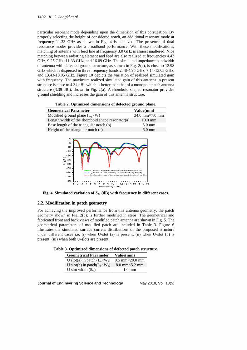
particular resonant mode depending upon the dimension of this corrugation. By
properly selecting the height of considered notch, an additional resonant mode at
frequency 11.33 GHz as shown in Fig. 4 is achieved. The presence of dual
resonance modes provides a broadband performance. With these modifications,
matching of antenna with feed line at frequency 3.0 GHz is almost unaltered. Nice
matching between radiating element and feed are also realized at frequencies 4.42
GHz, 9.25 GHz, 11.33 GHz, and 16.09 GHz. The simulated impedance bandwidth
of antenna with defected ground structure, as shown in Fig. 2(c), is close to 12.98
GHz which is dispersed in three frequency bands 2.48-4.95 GHz, 7.14-13.03 GHz,
and 13.43-18.05 GHz. Figure 10 depicts the variation of realized simulated gain
with frequency. The maximum realized simulated gain of this antenna in present
structure is close to 4.34 dBi, which is better than that of a monopole patch antenna
structure (3.39 dBi), shown in Fig. 2(a). A rhomboid shaped resonator provides
ground shielding and increases the gain of this antenna structure.
Table 2. Optimized dimensions of defected ground plane.
Geometrical Parameter Value(mm)
Modified ground plane (Lg×W) 34.0 mm×7.0 mm
Length/width of the rhomboid shape resonator(a) 10.0 mm
Base length of the triangular notch (b) 5.0 mm
Height of the triangular notch (c) 6.0 mm
Fig. 4. Simulated variation of S11 (dB) with frequency in different cases.
2.2. Modification in patch geometry
For achieving the improved performance from this antenna geometry, the patch
geometry shown in Fig. 2(c); is further modified in steps. The geometrical and
fabricated front and back views of modified patch antenna are shown in Fig. 5. The
geometrical parameters of modified patch are included in Table 3. Figure 6
illustrates the simulated surface current distributions of the proposed structure
under different cases i.e. (i) when U-slot (a) is present; (ii) when U-slot (b) is
present; (iii) when both U-slots are present.
Table 3. Optimized dimensions of defected patch structure.
Geometrical Parameter Value(mm)
U slot(a) in patch (La×Wa) 9.5 mm×20.0 mm
U slot(b) in patch(Lb×Wb) 8.0 mm×5.2 mm
U slot width (Sw) 1.0 mm

U-Shaped Slots Loaded Patch Antenna with Defected Ground Plane . . . . 1403
Journal of Engineering Science and Technology May 2018, Vol. 13(5)
Fig. 5. Front & back views of proposed patch
antenna (geometrical as well as fabricated model).
(i) 1.76 GHz
(ii) 5.57 GHz
(iii) 1.76 GHz & 5.30 GHz
Fig. 6. Surface current distributions in three considered cases (i) U slot
(a) is present (ii) U slot (b) is present (iii) Both U slots are present.
Fig. 7. Comparison between simulated reflection coefficients
with frequency in different cases of inserted slots.

1404 K. G. Jangid et al.
Journal of Engineering Science and Technology May 2018, Vol. 13(5)
3. Results and Discussion
After extensive optimizations, the prototype of antenna showing triple band
performance is developed and the design parameters of this prototype are listed in
Tables 2 and 3. The measured and simulation results of reflection coefficient S11
are shown in Fig. 8. The measured results are obtained through R & S make Vector
network analyser (ZVA 40). The measured results shown in Fig. 8 provide a wide
impedance bandwidth extended between frequency range 2.29 GHz to 17.28 GHz
for S11 < -10 dB, with rejection band lying in frequency range 5.49 GHz - 6.83 GHz
for S11> -10 dB. The presence of higher order modes due to monopole structure and
triangular notch in ground plane significantly contributes in the enhancement of
impedance bandwidth. An additional frequency band spread in between 1.733 GHz
to 1.89 GHz frequency range is also realized. Measured results also demonstrate a
nice matching between radiating element and feed at frequencies 1.81 GHz, 3.00
GHz, 4.22 GHz, 7.33 GHz, 9.34 GHz and 14.24 GHz. A reasonable agreement
between experimental and simulated results is realized. The minor deviation
between simulated and experimental results is perhaps due to fabrication error and
associated measurement limitations.
Figures 9(a) and (d) illustrate the simulated surface current distribution of the
proposed structure at 1.76 GHz and 5.30 GHz. The maximum current density
appears mainly along the U-shaped slots at the patch, which are responsible for first
(1.76 GHz), and third (5.30 GHz) resonance frequencies. Inserted U-shaped slots
on patch corresponding to these frequencies are working as individual leaky
resonators and maximum currents on the patch are flowing along the outer and
inner edges of the slots [24]. The surface currents are more centralized around the
slots in the structure and hence for each introduced slot; a resonant frequency band
is generated. These frequency bands are useful for GSM 1800 MHz and
WLAN/WiMAX communication systems. Figures 9(b) and (e) indicate that the
maximum surface currents mostly centralize near the feed line and radiation patch.
The triangular notch in ground plane is responsible for resonance frequencies 3.18
GHz & 9.15 GHz, which are depicted in Figs. 9(c) and (f). A comparison of gain
performance of antenna in different situation is shown in Fig. 10. On introducing a
rhomboid shape resonator in bottom side of antenna, an increase in gain of antenna
in lower frequency band may be obtained. The maximum measured gain of antenna
is approximate 6.59 dBi at 4.40 GHz which is shown in Fig. 11.
Fig. 8. Measured and Simulated variation of S11 (dB) with frequency.

U-Shaped Slots Loaded Patch Antenna with Defected Ground Plane . . . . 1405
Journal of Engineering Science and Technology May 2018, Vol. 13(5)
(a) 1.76 GHz
(b) 3.18 GHz
(c) 3.18 GHz
(d) 5.30 GHz
(e) 9.15 GHz
(f) 9.15 GHz
Fig. 9. Simulated surface current distributions
of the modified structure at various frequencies.
Fig. 10. Simulated variation of gain with frequency in three different cases.
Fig. 11. Variation of measured gain with frequency of proposed structure.
1406 K. G. Jangid et al.
Journal of Engineering Science and Technology May 2018, Vol. 13(5)
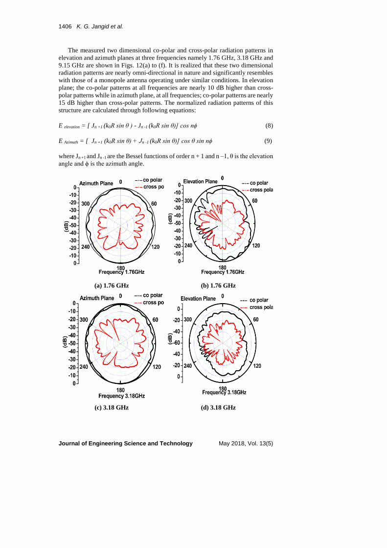
The measured two dimensional co-polar and cross-polar radiation patterns in
elevation and azimuth planes at three frequencies namely 1.76 GHz, 3.18 GHz and
9.15 GHz are shown in Figs. 12(a) to (f). It is realized that these two dimensional
radiation patterns are nearly omni-directional in nature and significantly resembles
with those of a monopole antenna operating under similar conditions. In elevation
plane; the co-polar patterns at all frequencies are nearly 10 dB higher than cross-
polar patterns while in azimuth plane, at all frequencies; co-polar patterns are nearly
15 dB higher than cross-polar patterns. The normalized radiation patterns of this
structure are calculated through following equations:
E elevation = [ Jn +1 (k0R sin θ ) - Jn -1 (k0R sin θ)] cos nϕ (8)
E Azimuth = [ Jn +1 (k0R sin θ) + Jn -1 (k0R sin θ)] cos θ sin nϕ (9)
where Jn +1 and Jn -1 are the Bessel functions of order n + 1 and n –1, θ is the elevation
angle and ϕ is the azimuth angle.
(a) 1.76 GHz (b) 1.76 GHz
(c) 3.18 GHz (d) 3.18 GHz

U-Shaped Slots Loaded Patch Antenna with Defected Ground Plane . . . . 1407
Journal of Engineering Science and Technology May 2018, Vol. 13(5)
(e) 9.15 GHz (f) 9.15 GHz
Fig. 12. Measured 2-D radiation patterns in elevation (E-plane)
and azimuth (H-Plane) planes at different resonance frequencies.
The polarization of proposed design has performed at several (θ, ϕ) values and
finally with θ= 50° & ϕ= 74°, the best performance of the antenna is achieved. The
simulated variation of axial ratio as a function of frequency is shown in Fig. 13. It
indicates that antenna is presenting circular polarization in the frequency range 4.12
GHz to 5.20 GHz with axial ratio bandwidth close to 1.08 GHz.
Fig. 13. Simulated variation of axial ratio with frequency.
The numerical simulation of the SAR values has evaluated on Specific
Anthropomorphic Mannequin phantom head through CST Simulation program.
This head is modelled by a shell filled with a liquid, which represent the average
material properties of the head. The SAR values averaged over 1g biological tissue
and are obtained by selecting IEEE standard [25]. The simulated power 0.5 W has
used and SAR calculation performed in the post processing phase of the simulation.
Figure 14 shows the geometry of the SAM model with proposed antenna.

1408 K. G. Jangid et al.
Journal of Engineering Science and Technology May 2018, Vol. 13(5)
Fig. 14. Geometry of
SAM Head Hand model
with proposed antenna.
(a) 1.8 GHz (b) 2.4 GHz
Fig. 15. SAR values at different frequencies.
The effect of the human head on SAR values has studied at 1.8 GHz and 2.4 GHz,
which is depicted in Fig. 15. The SAR values at 1.8 GHz is 0.000063749 W/kg and
at 2.4 GHz is 0.00036884 W/kg for 1 gram of tissue on two frequency which are well
interior the value specified by the FCC (1.6 W/kg). The proposed antenna acquired
lower SAR values in the human head than that of a dipole and helical antenna.
4. Conclusions
This paper provides design and performance of a U-shaped slots loaded patch
structure with modified ground plane through simulation and measured results.
This antenna provides triple band performance with impedance bandwidths 157
MHz (in frequency range 1.733 to 1.89 GHz), 3.2 GHz (in frequency range 2.29 to
5.49 GHz) & 10.45 GHz (in frequency range 6.83 to 17.28 GHz), axial impedance
bandwidth 1.08 GHz (in frequency range 4.12 GHz to 5.20 GHz), nearly flat gain
(close to 6.5 dBi) and good radiation patterns and acceptable SAR value in the
desired range. The maximum gain of the antenna is close to 6.59 dBi at 4.40 GHz.
This antenna may be proved as a useful structure for modern radio communication
systems including in Mobile and Bluetooth application, WLAN, WiMAX and
UWB communication systems.
Acknowledgement
Authors are thankful to Department of Electronics & Information Technology, New
Delhi and MHRD’s DIC programme for providing financial support for the present
work. Authors also extend their sincere thanks to Mr. V.V. Srinivasan, ISRO
Satellite Centre, Bangalore and Mr. Fetah Lohar, Application Engineer, Jyoti
Electronics for their valuable suggestions in this work.
References
1. Kumar, G.; and Ray, K.P. (2003). Broadband microstrip antenna.
Massachusetts: Artech House.
2. Bahl, I.J.; and Bhartia, P. (1980). Microstrip antennas. Massachusetts:
Artech House.

U-Shaped Slots Loaded Patch Antenna with Defected Ground Plane . . . . 1409
Journal of Engineering Science and Technology May 2018, Vol. 13(5)
3. Chang, T.-H.; and Kiang, J.-F. (2013). Compact multi-band H-shaped slot
antenna. IEEE Transactions on Antennas and Propagation, 61(8), 4345-4349.
4. Tang, H.; Wang, K; and Wu, R. (2017). Compact triple-band circularly
polarized monopole antenna for WLAN and WiMAX application. Microwave
and Optical Technology Letters, 59 (8), 1901-1908.
5. Chang, C.H.; Wei, W.C.; Ma, P.J.; and Huang, S. Y. (2013). Simple printed
WWAN monopole slot antenna with parasitic shorted strips for slim mobile
phone application. Microwave and Optical Technology Letters, 55(12),
2835-2841.
6. Mondal, K.; and Sarkar, P.P. (2017). Dual band compact monopole antenna
for ISM 2.4/5.8 Frequency bands with bluetooth, wi-fi, and mobile
applications. Microwave and Optical Technology Letters, 59(5), 1061-1065.
7. Liu, Y.T.; and Su, C.W. (2008). Wideband omni-directional operation monopole
antenna. Progress in Electromagnetics Research Letters, 1, 255-261.
8. Malik; Patnaik, A.; and Kartikeyan, M.V.A. (2015). Compact dual band
antenna with omnidirectional radiation pattern. IEEE Antennas and Wireless
Propagation Letters, 14, 503-506.
9. Ray, K.P.; Thakur, S.S.; and Deshmukh R.A. (2012). Wideband L-shaped
printed monopole antenna. International Journal of Electronics &
Communication, 66(8), 693-696.
10. Yeo, W.L.; Lai, K.C.; Yeap, K.H.; Teh, P.C; and Nisar, H.A. (2017). A
compact dual-band hook-shaped antenna for wireless application. Wideband
L-shaped printed monopole antenna. Microwave and Optical Technology
Letters, 59(8), 1882-1887.
11. Chitra, R.J.; and Nagarajan, V. (2013). Double L-slot microstrip patch antenna
array for WIMAX and WLAN application. Computers and Electrical
Engineering, 39, 1026-1041.
12. Beigi, P.; Nourinia, J.; Zehforoosh, Y.; and Mohammadi, B. (2015). A compact
novel CPW-FED antenna with square spiral patch for multiband applications.
Microwave and Optical Technology Letters, 57(1), 111-115.
13. Hsieh, D.H.; Wu, J.W.; Cheng, Y.W.; and Wang, C.J. (2015). A CPW fed
meandered-shaped monopole antenna with asymmetrical ground planes.
Proceedings of the IEEE Radio and Wireless Symposium (RWS ’15). San
Diego, California, United States of America, 86-88.
14. Liu, P.; Zou, Y.; Xie, B.; Liu, X.; and Sun, B. (2012). Compact CPW fed tri-
band printed antenna with meandering split-ring slot for WLAN/WiMAX
applications. IEEE Antennas and Wireless Propagation Letters, 11, 1242-1244.
15. Pei; W., A.G.; Gao, S.; and Leng, W. (2011). Miniaturized triple-band antenna
with a defected ground plane for WLAN/WiMAX applications. IEEE
Antennas and Wireless Propagation Letters, 10, 298–301.
16. Deng, C.; Li, Y.; Zhang, Z.; and Feng, Z. (2015). Planar printed multi resonant
antenna for octa-band WWAN/LTE mobile handset. IEEE Antennas and
Wireless Propagation Letters, 14, 1734–1737.
17. Kim, D.O.; Kim, C.Y.; Yang, D.G.; and Ahmed, M.S. (2017). Multiband
omnidirectional planar monopole antenna with two split ring resonator pairs.
Microwave and Optical Technology Letters, 59(4), 753-758.

1410 K. G. Jangid et al.
Journal of Engineering Science and Technology May 2018, Vol. 13(5)
18. Guo, Z.; Tian, H.; Wang, X.; Luo, Q.; and Ji, Y. (2013). Bandwidth
enhancement of monopole UWB antenna with new slots and EBG structures.
IEEE Antennas and Wireless Propagation Letters, 12, 1550- 1553.
19. Goswami, S.A.; and Karia, D. (2017). A compact monopole antenna for
wireless applications with enhanced bandwidth. AEU-International Journal of
Electronic and Communications, 72, 33-39.
20. Neebha, T.M.; and Nesasudha M. (2016). Design and analysis of advanced
microstrip patch antenna for endoscopic capsules. Microwave and Optical
Technology Letters, 58(7), 1762-1767.
21. Simulia, D.S. (2014). Computer simulation technology. Retrieved May 10,
2016, from http://www.cst.com.
22. Balanis, C.A. (2005). Antenna theory: Analysis & design (3rd ed.). New York:
John Wiley and Sons Inc.
23. Lin, C.C.; and Chuang, H.R. (2008). A 3-12 GHz UWB planar triangular
monopole antenna with ridged ground-plane. Progress in Electromagnetics
Research, 83, 307-321.
24. Ghalibafan, J.; Attari, A.R.; and Hojjat-Kashani, F. (2010). A new dual-band
microstrip antenna with U-shaped slot. Progress in Electromagnetics
Research C, 12, 215-223.
25. Means, D.L.; and Chan K.W. (2001). Evaluating compliance with Federal
Communications Commision (FCC) guidelines for human exposure to
radiofrequency electromagnetic fields. FCC's Office of Engineering and
Technology's World Wide Web, OET bulletin 65, edition 97-01.