uav engine efi components specifications manual uav engine efi components specs -v2.1.pdf · uav...
TRANSCRIPT
UAV engine EFI components
Specifications Manual
-In miniature sizes
- For 20cc to 300cc engines
V2.1
COPY RIGHTS ECOTRONS LLC
ALL RIGHTS RESERVED
Http://www.ecotrons.com
Note: If you are not sure about any specific details, please
contact us at [email protected].
Index Page Revision Date Note
1 First Edition 5.3.2015 V1.0
2 Second Edition 6.5.2016 V1.5
3 Third Edition 3.1.2017 V1.6
4 Fourth Edition 6.14.2017 V1.7
5 Fifth Edition 10.8.2018 V1.8
6 -- 2.14.2019 V2.0
7 -- 3.27.2019 V2.1
UAV engine EFI Components Specs –V2.1
1 Copy right ECOTRONS LLC http://www.ecotrons.com
Contents
1. UAV EFI System Overview ......................................................................................................................... 1
1.1 EFI System Block Diagram .......................................................................................................... 1
1.2 Control Strategy Block Diagram.................................................................................................. 2
2. ECU ................................................................................................................................................................ 4
2.1 ECU Overview ............................................................................................................................... 4
2.2 ECU Technical Parameters.......................................................................................................... 5
2.3 ECU Pin Definition and Description............................................................................................ 6
2.4 ECU Mechanical CAD drawing and dimensions ...................................................................... 7
3. EFI Harness .................................................................................................................................................. 8
4. UAV CDI ........................................................................................................................................................ 9
4.1 UAV CDI Overview ................................................................................................................................ 9
4.2 Technical Parameters ......................................................................................................................... 10
5. Throttle Body .............................................................................................................................................. 11
5.1 Throttle body with servo assembled ......................................................................................... 11
5.2 Mechanical CAD drawing........................................................................................................... 12
6. Fuel supply system .................................................................................................................................... 15
6.1 Rotor pump oil supply system ........................................................................................................... 15
6.1.1 Picture of Fuel pump ........................................................................................................................... 15
6.1.2 Connect instructions for rotor pump assembly (Unit: mm)................................................................ 16
6.1.3 Mechanical Dimensions of the fuel pump ........................................................................................... 17
6.1.4 Fuel pressure regulator .................................................................................................................... 17
6.2 Gear pump oil supply system ............................................................................................................ 19
6.2.1 Picture of Fuel pump ........................................................................................................................... 19
6.2.2 Connect instructions for Gear pump assembly ................................................................................... 20
6.2.3 Mechanical Dimensions of the fuel pump (Unit: mm) ....................................................................... 21
6.2.4 Gear Pump controller ......................................................................................................................... 22
6.2.5 Check value ...................................................................................................................................... 24
6.3 Fuel injector.................................................................................................................................... 25
7. Barometric Pressure Sensor .................................................................................................................... 27
7.1 BARO sensor ............................................................................................................................... 27
7.2 Sensor electrical parameters ..................................................................................................... 27
8. Map Sensor (Optional for 4 stroke engine only) .................................................................................... 28
8.1 Electrical connection ................................................................................................................... 28
UAV engine EFI Components Specs –V2.1
2 Copy right ECOTRONS LLC http://www.ecotrons.com
8.2 Sensor electrical parameters ..................................................................................................... 28
8.3 Nominal characteristic curve ..................................................................................................... 29
8.4 Mechanical CAD Drawing .......................................................................................................... 29
9. TPS sensor (optional for 60cc or bigger engines) ................................................................................ 30
9.1 Circuit diagram of TPS ............................................................................................................... 30
9.2 Electrical connection ................................................................................................................... 30
9.3 Output characteristics ................................................................................................................. 31
9.4 Sensor specifications .................................................................................................................. 31
10. Servo motor .................................................................................................................................................. 32
10.1 Servo motor Picture .......................................................................................................................... 32
10.2 Servo motor electrical characteristics ........................................................................................ 32
10.3 Mechanical CAD Drawing ............................................................................................................ 33
11. Temperature sensors .................................................................................................................................. 33
11.1 Intake air temperature sensor (IAT) ................................................................................................ 33
11.2 Engine temperature sensor ......................................................................................................... 34
12. Hall sensor ................................................................................................................................................... 36
12.1 Hall sensor Picture ........................................................................................................................ 36
12.2 Hall sensor Parameters ................................................................................................................ 36
12.3 Pin-out definitions .......................................................................................................................... 37

UAV engine EFI Components Specs –V2.1
1 Copy right ECOTRONS LLC http://www.ecotrons.com
To meet the requirement of UAV small engine EFI
systems, Ecotrons has developed a series of mini-size
EFI components.
1. UAV EFI System Overview
1.1 EFI System Block Diagram
Abbreviation:
IAT: Intake Air Temperature Sensor
CHT: Engine Temperature or Cylinder Head Temperature Sensor
BARO: Barometric Pressure Sensor
MAP: Manifold Absolute Pressure Sensor
UAV engine EFI Components Specs –V2.1
2 Copy right ECOTRONS LLC http://www.ecotrons.com
TPS: Throttle Position Sensor
KEYSW: Key Switch or Ignition Switch input
CKP: Crank Position Sensor
ROUT: Relay control Output
INJ: Injector control output
CDI: Capacitor Discharge Ignition Controls
SERVO: Servo motor which controls the throttle position
CAN: Controller Area Network or CAN bus
FGP: Gear Pump
FRP: Rotary Pump
Knock: Knock sensor for ignition control closed-loop
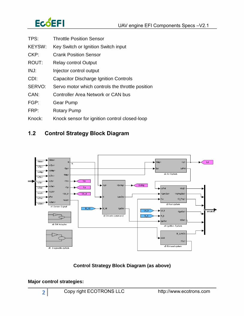
1.2 Control Strategy Block Diagram
Control Strategy Block Diagram (as above)
Major control strategies:
UAV engine EFI Components Specs –V2.1
3 Copy right ECOTRONS LLC http://www.ecotrons.com
• Charge detection and prediction.
• Fuel injection controls.
• Ignition system controls.
• Fuel pump controls.
• Idle speed controls
• Transient fuel compensations.
• Decel-fuel-cut-off.
• Altitude compensations.
• Temperature compensations (winter, summer, etc.).
• Engine protections.
• Diagnostics and serial communications.
• Servo motor controls (optional).
• Knock Control (optional).
UAV engine EFI Components Specs –V2.1
4 Copy right ECOTRONS LLC http://www.ecotrons.com
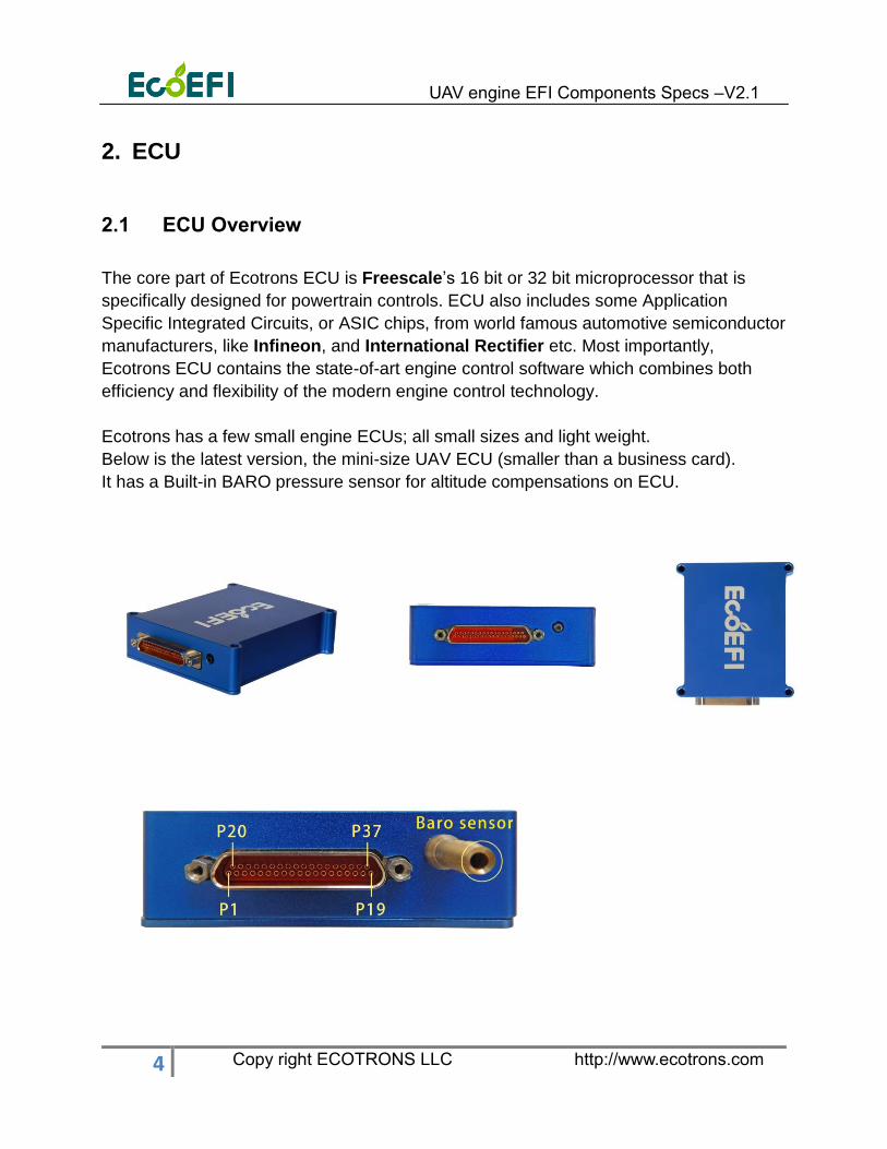
2. ECU
2.1 ECU Overview
The core part of Ecotrons ECU is Freescale’s 16 bit or 32 bit microprocessor that is
specifically designed for powertrain controls. ECU also includes some Application
Specific Integrated Circuits, or ASIC chips, from world famous automotive semiconductor
manufacturers, like Infineon, and International Rectifier etc. Most importantly,
Ecotrons ECU contains the state-of-art engine control software which combines both
efficiency and flexibility of the modern engine control technology.
Ecotrons has a few small engine ECUs; all small sizes and light weight.
Below is the latest version, the mini-size UAV ECU (smaller than a business card).
It has a Built-in BARO pressure sensor for altitude compensations on ECU.
UAV engine EFI Components Specs –V2.1
5 Copy right ECOTRONS LLC http://www.ecotrons.com
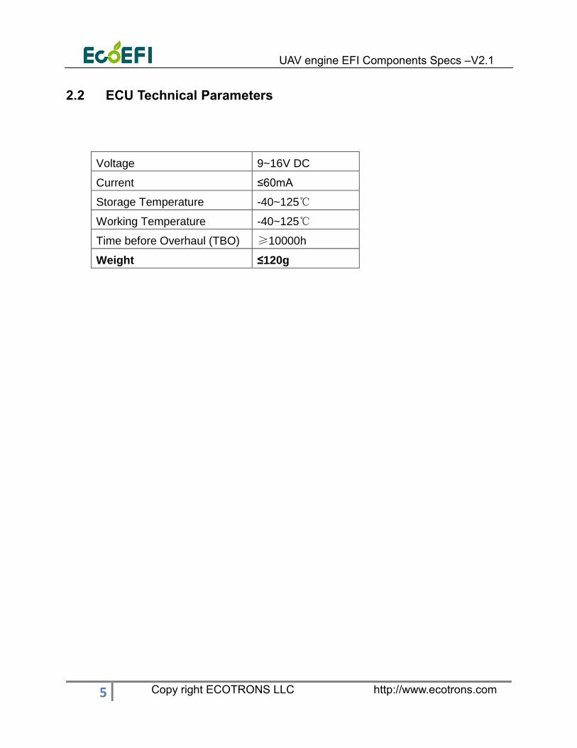
2.2 ECU Technical Parameters
Voltage 9~16V DC
Current ≤60mA
Storage Temperature -40~125℃
Working Temperature -40~125℃
Time before Overhaul (TBO) ≥10000h
Weight ≤120g
UAV engine EFI Components Specs –V2.1
6 Copy right ECOTRONS LLC http://www.ecotrons.com
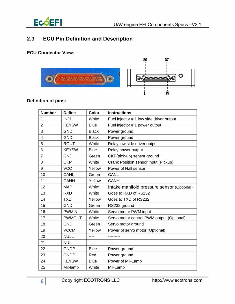
2.3 ECU Pin Definition and Description
ECU Connector View:
Definition of pins:
Number Define Color instructions
1 INJ1 White Fuel injector # 1 low side driver output
2 KEYSW Blue Fuel injector # 1 power output
3 GND Black Power ground
4 GND Black Power ground
5 ROUT White Relay low side driver output
6 KEYSW Blue Relay power output
7 GND Green CKP(pick-up) sensor ground
8 CKP White Crank Position sensor input (Pickup)
9 VCC Yellow Power of Hall sensor
10 CANL Green CANL
11 CANH Yellow CANH
12 MAP White Intake manifold pressure sensor (Optional)
13 RXD White Goes to RXD of RS232
14 TXD Yellow Goes to TXD of RS232
15 GND Green RS232 ground
16 PWMIN White Servo motor PWM input
17 PWMOUT White Servo motor control PWM output (Optional)
18 GND Green Servo motor ground
19 VCCM Yellow Power of servo motor (Optional)
20 NULL ---- ---------
21 NULL ---- ---------
22 GNDP Blue Power ground
23 GNDP Red Power ground
24 KEYSW Blue Power of Mil-Lamp
25 Mil-lamp White Mil-Lamp
UAV engine EFI Components Specs –V2.1
7 Copy right ECOTRONS LLC http://www.ecotrons.com
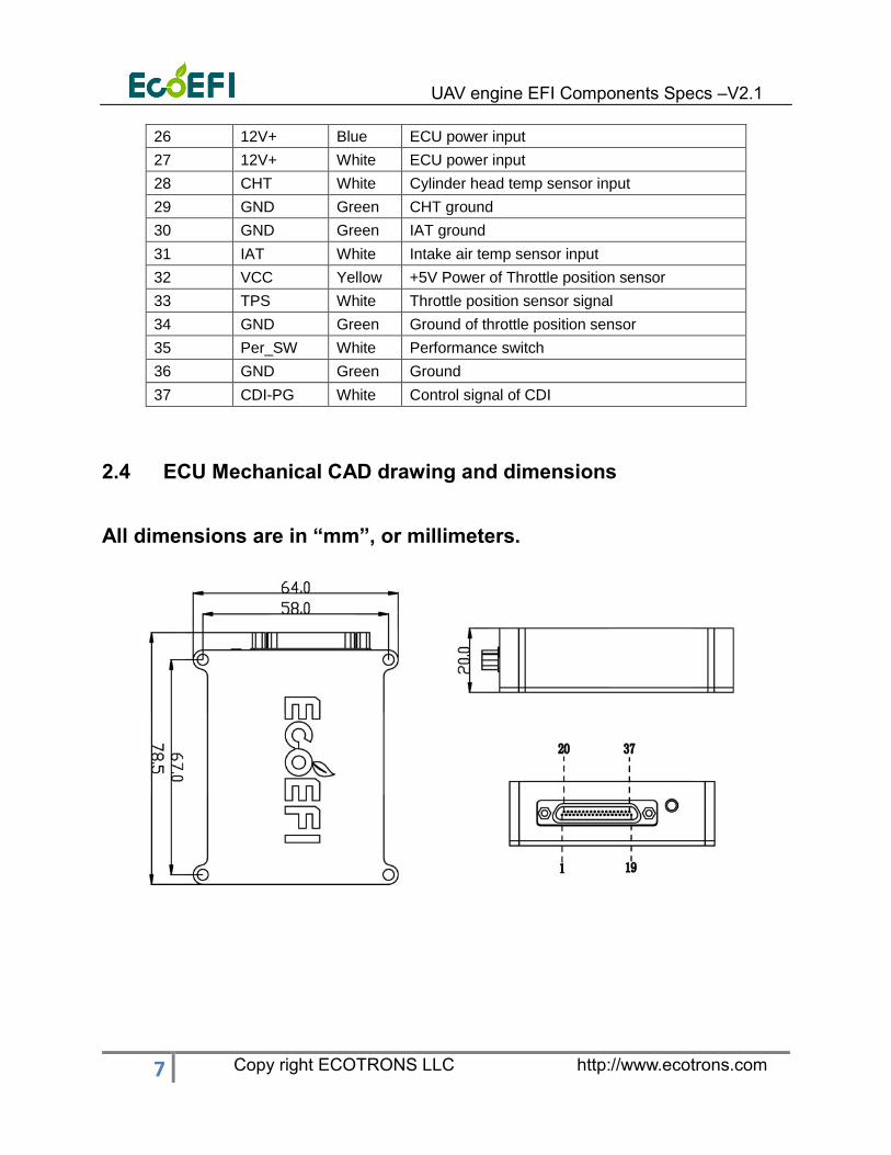
26 12V+ Blue ECU power input
27 12V+ White ECU power input
28 CHT White Cylinder head temp sensor input
29 GND Green CHT ground
30 GND Green IAT ground
31 IAT White Intake air temp sensor input
32 VCC Yellow +5V Power of Throttle position sensor
33 TPS White Throttle position sensor signal
34 GND Green Ground of throttle position sensor
35 Per_SW White Performance switch
36 GND Green Ground
37 CDI-PG White Control signal of CDI
2.4 ECU Mechanical CAD drawing and dimensions
All dimensions are in “mm”, or millimeters.
UAV engine EFI Components Specs –V2.1
8 Copy right ECOTRONS LLC http://www.ecotrons.com
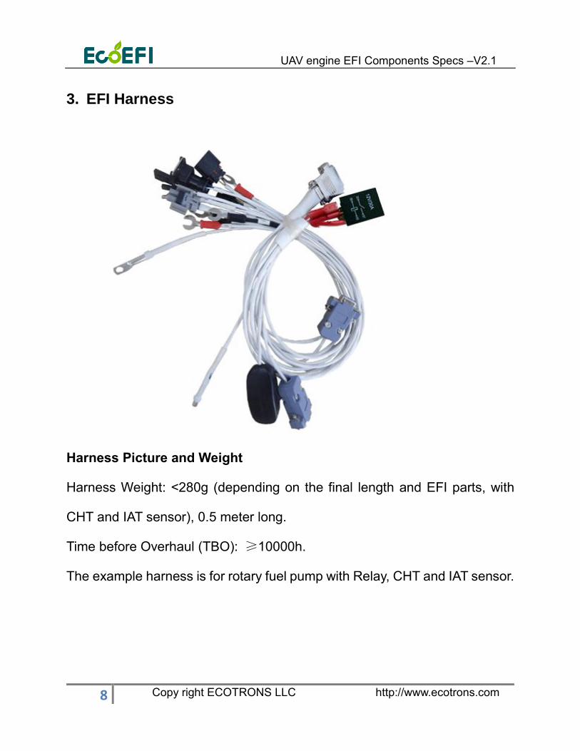
3. EFI Harness
Harness Picture and Weight
Harness Weight: <280g (depending on the final length and EFI parts, with
CHT and IAT sensor), 0.5 meter long.
Time before Overhaul (TBO): ≥10000h.
The example harness is for rotary fuel pump with Relay, CHT and IAT sensor.
UAV engine EFI Components Specs –V2.1
9 Copy right ECOTRONS LLC http://www.ecotrons.com
4. UAV CDI
4.1 UAV CDI Overview
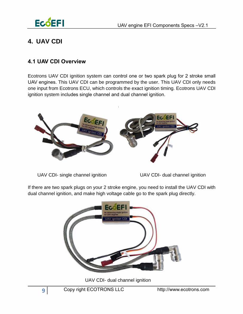
Ecotrons UAV CDI ignition system can control one or two spark plug for 2 stroke small
UAV engines. This UAV CDI can be programmed by the user. This UAV CDI only needs
one input from Ecotrons ECU, which controls the exact ignition timing. Ecotrons UAV CDI
ignition system includes single channel and dual channel ignition.
UAV CDI- single channel ignition UAV CDI- dual channel ignition
If there are two spark plugs on your 2 stroke engine, you need to install the UAV CDI with
dual channel ignition, and make high voltage cable go to the spark plug directly.
UAV CDI- dual channel ignition

UAV engine EFI Components Specs –V2.1
10 Copy right ECOTRONS LLC http://www.ecotrons.com
4.2 Technical Parameters
Total CDI system weight: 120g
Power supply: 12V
CDI Unit Size: 50x38x29mm
Time before Overhaul (TBO): ≥5000h
1) Minimum RPM limitation of firing: < 250 r/min
2) Working RPM range: 250r/min~11000r/min
3) Withstand voltage: The secondary peak voltage 35kV, without breakdown in
continuously 1 minute.
4) Resistance between primary and secondary coil.
Measured with digital multimeter: Primary coil 4.0Ω+10%:
Secondary coil:13.5kΩ+10%
Measured with Digital inductance meter: Primary coil: 6.5mH+1 0%
Measured with bridge: Secondary coil: 20H+10%
5) Spark cap resistance: 5kΩ+10%
6) The secondary peak voltage: when the primary voltage is 200V, the secondary
voltage is higher than 22kV.
7) Without breakdown in continuously 30 seconds, 2500r/min
UAV engine EFI Components Specs –V2.1
11 Copy right ECOTRONS LLC http://www.ecotrons.com
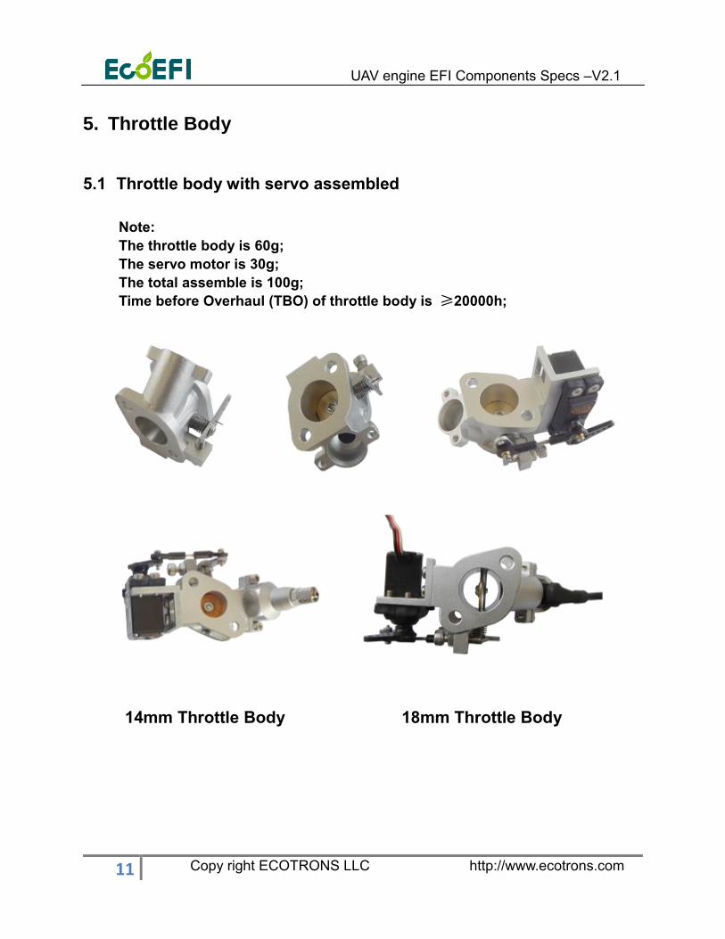
5. Throttle Body
5.1 Throttle body with servo assembled
Note:
The throttle body is 60g;
The servo motor is 30g;
The total assemble is 100g;
Time before Overhaul (TBO) of throttle body is ≥20000h;
14mm Throttle Body 18mm Throttle Body

UAV engine EFI Components Specs –V2.1
12 Copy right ECOTRONS LLC http://www.ecotrons.com
22mm Throttle Body 28mm Throttle Body
34mm Throttle Body
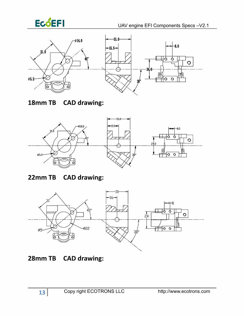
5.2 Mechanical CAD drawing
14mm TB CAD drawing:
UAV engine EFI Components Specs –V2.1
13 Copy right ECOTRONS LLC http://www.ecotrons.com
18mm TB CAD drawing:
22mm TB CAD drawing:
28mm TB CAD drawing:
UAV engine EFI Components Specs –V2.1
14 Copy right ECOTRONS LLC http://www.ecotrons.com
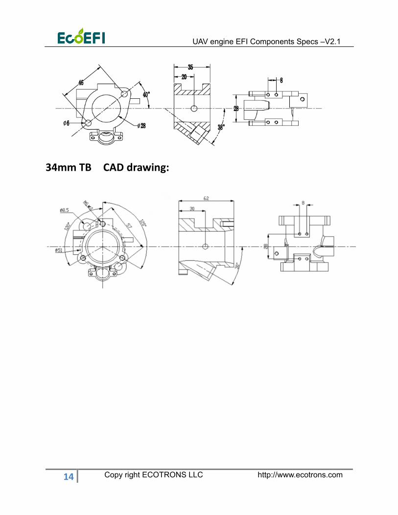
34mm TB CAD drawing:
UAV engine EFI Components Specs –V2.1
15 Copy right ECOTRONS LLC http://www.ecotrons.com
6. Fuel supply system
We have two kinds of fuel supply system, one is composed of rotor pump and oil pressure
regulator, the other is composed of gear pump and gear pump controller. In comparison,
the gear pump system is light in weight and low in power consumption.
Basic characteristics
Rotor Pump Gear Pump
Supply voltage 12VDC (+11~15) VDC
Working current <=2A <1.5A
Flow 25L/h >=12L/h@3bar
Weight 185g 80g
Installation Style External External
Working temperature (-40~+80 )o C (-25~+70) o C
Fuel type Gasoline
Gasoline with <=20% ethanol
Gasoline
Gasoline with <=20% ethanol
Storage Temp Range -30 o C~60 o C -20~100 o C
Humidity <=60% --
Time before Overhaul
(TBO)
>=2000h >=500h
Storage period <=2 years --
6.1 Rotor pump oil supply system
6.1.1 Picture of Fuel pump

UAV engine EFI Components Specs –V2.1
16 Copy right ECOTRONS LLC http://www.ecotrons.com
Rotor Pump
6.1.2 Connect instructions for rotor pump assembly (Unit: mm)
Note: the bracket of the oil pump needs to be purchased separately. The default
parts list does not contain it.
UAV engine EFI Components Specs –V2.1
17 Copy right ECOTRONS LLC http://www.ecotrons.com
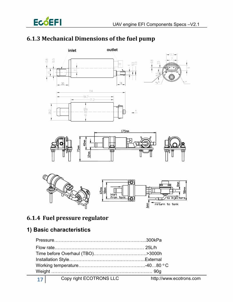
6.1.3 Mechanical Dimensions of the fuel pump
6.1.4 Fuel pressure regulator
1) Basic characteristics
Pressure……………………………………………….…...300kPa
Flow rate…………………………………………..……… 25L/h
Time before Overhaul (TBO)……………………….…….>3000h
Installation Style…………………………….…………….External
Working temperature………………………………….….-40…80 o C
Weight …………………………………………..…………..… 90g
UAV engine EFI Components Specs –V2.1
18 Copy right ECOTRONS LLC http://www.ecotrons.com
Fuel:
…………………………………………………….Gasoline
…………………………………………………....Gasoline with <=20% ethanol
Storage:
Storage Temp Range ……………….…..….-30 o C …60 o C
Humidity…………………………………..…<=60%
Storage period……………….………………<=2 years
2) Pictures and Mechanical CAD Drawing
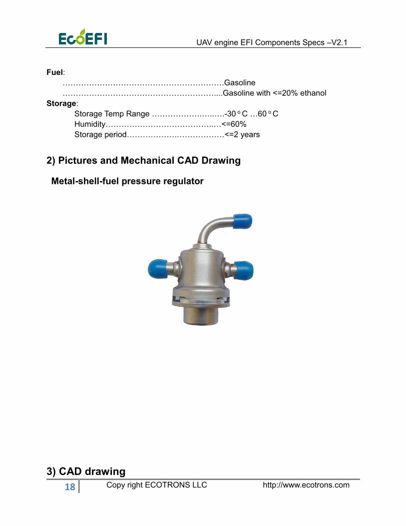
Metal-shell-fuel pressure regulator
3) CAD drawing

UAV engine EFI Components Specs –V2.1
19 Copy right ECOTRONS LLC http://www.ecotrons.com
6.2 Gear pump oil supply system
6.2.1 Picture of Fuel pump
Gear Pump

UAV engine EFI Components Specs –V2.1
20 Copy right ECOTRONS LLC http://www.ecotrons.com
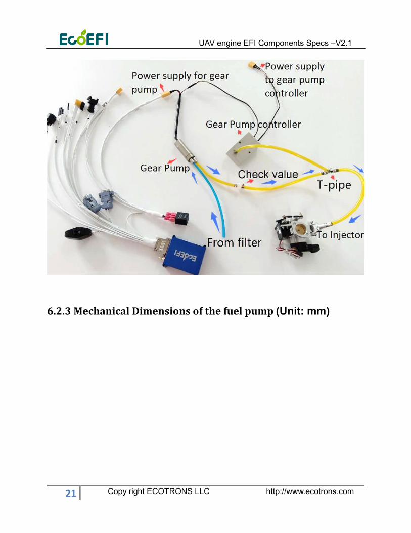
6.2.2 Connect instructions for Gear pump assembly
Fuel tank
Filte
rInjector
Check valve T-pipe
Gear Pump Controller
Gear pump
UAV engine EFI Components Specs –V2.1
21 Copy right ECOTRONS LLC http://www.ecotrons.com
6.2.3 Mechanical Dimensions of the fuel pump (Unit: mm)

UAV engine EFI Components Specs –V2.1
22 Copy right ECOTRONS LLC http://www.ecotrons.com
6.2.4 Gear Pump controller
1) Gear Pump controller (EMCU-BL-2) is the controller from ECOTRONS, which is
designed for EFI micro gear pump controls to provide constant fuel pressure (3Bar or
43.5psi). Gear Pump Controller can keep constant fuel pressure, and you do not need an
external fuel pressure regulator.
UAV engine EFI Components Specs –V2.1
23 Copy right ECOTRONS LLC http://www.ecotrons.com
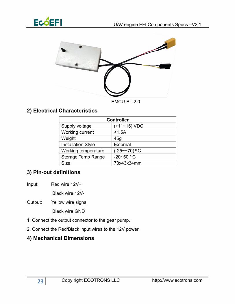
EMCU-BL-2.0
2) Electrical Characteristics
Controller
Supply voltage (+11~15) VDC
Working current <1.5A
Weight 45g
Installation Style External
Working temperature (-25~+70) o C
Storage Temp Range -20~50 o C
Size 73x43x34mm
3) Pin-out definitions
Input: Red wire 12V+
Black wire 12V-
Output: Yellow wire signal
Black wire GND
1. Connect the output connector to the gear pump.
2. Connect the Red/Black input wires to the 12V power.
4) Mechanical Dimensions

UAV engine EFI Components Specs –V2.1
24 Copy right ECOTRONS LLC http://www.ecotrons.com
6.2.5 Check value
Note: Check value is only used with gear fuel pump (weight <1g)
Working pressure: 3Bar ( Gauge pressure)
CAD drawing:
UAV engine EFI Components Specs –V2.1
25 Copy right ECOTRONS LLC http://www.ecotrons.com
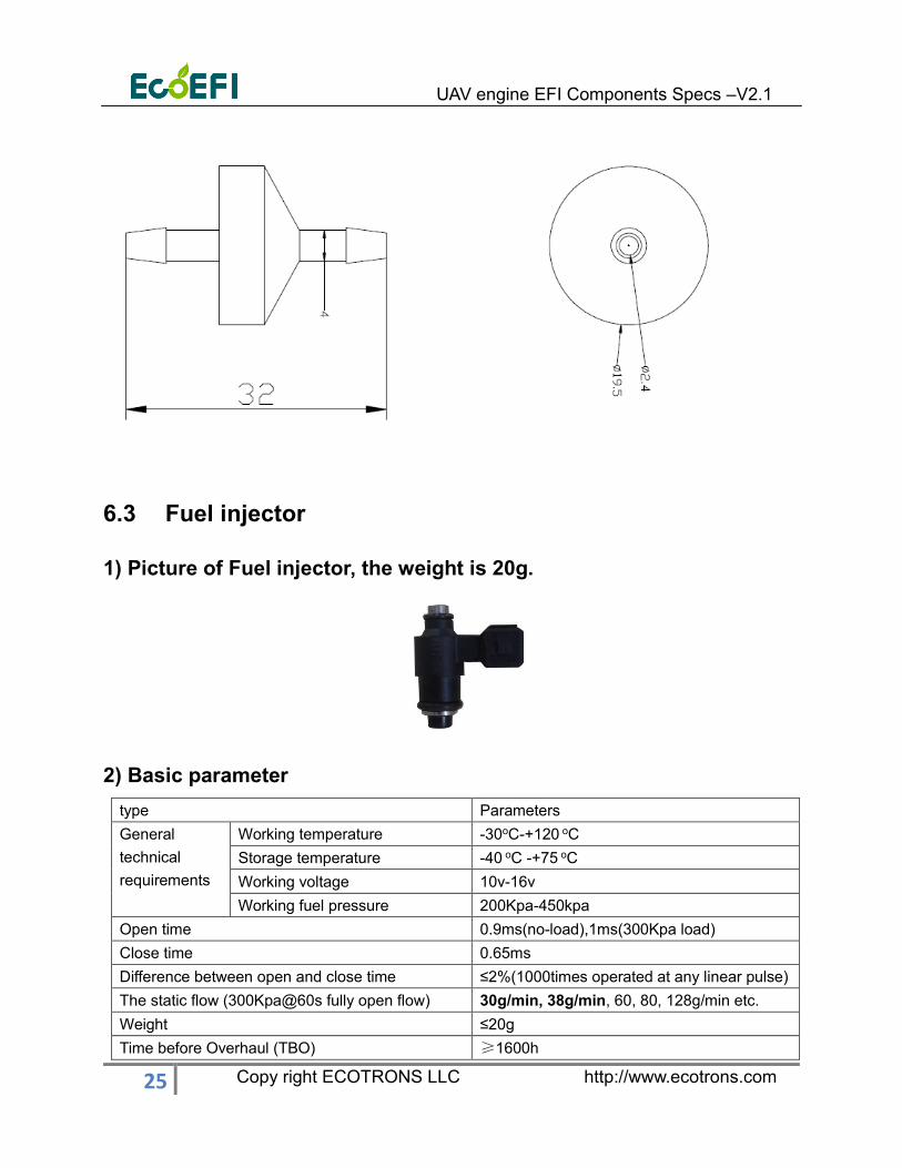
6.3 Fuel injector
1) Picture of Fuel injector, the weight is 20g.
2) Basic parameter
type Parameters
General
technical
requirements
Working temperature -30oC-+120 oC
Storage temperature -40 oC -+75 oC
Working voltage 10v-16v
Working fuel pressure 200Kpa-450kpa
Open time 0.9ms(no-load),1ms(300Kpa load)
Close time 0.65ms
Difference between open and close time ≤2%(1000times operated at any linear pulse)
The static flow (300Kpa@60s fully open flow) 30g/min, 38g/min, 60, 80, 128g/min etc.
Weight ≤20g
Time before Overhaul (TBO) ≥1600h

UAV engine EFI Components Specs –V2.1
26 Copy right ECOTRONS LLC http://www.ecotrons.com
Coil resistance 12Ω~14.5Ω
Uniformity of the static and dynamic flow <±3%
The offset of the spraying flow <±3%
Dynamic flow linear error <±3%
Required
operating
voltage
The minimum voltage for operating <7v
The required overload operating
voltage
after24@60s: the offset of dynamic flow<
±4%
Seal leakage <0.3cc/min(400kpa)
Atomized particle (50% SMD) 70
Low temperature test
Dynamic flow<±3%
Seal leakage <0.3cc/min(400kpa)
High temperature test
Thermal shock test
Physical performance test
Durability test for 0.6billion
Socket performance test of injectors In accordance with QC/T417
Noise performance test of injectors <70db(A)
Salt performance test of injectors No corrosion marks on the injectors
Offset of dynamic flow <±3%,
3) Mechanical CAD Drawing
UAV engine EFI Components Specs –V2.1
27 Copy right ECOTRONS LLC http://www.ecotrons.com
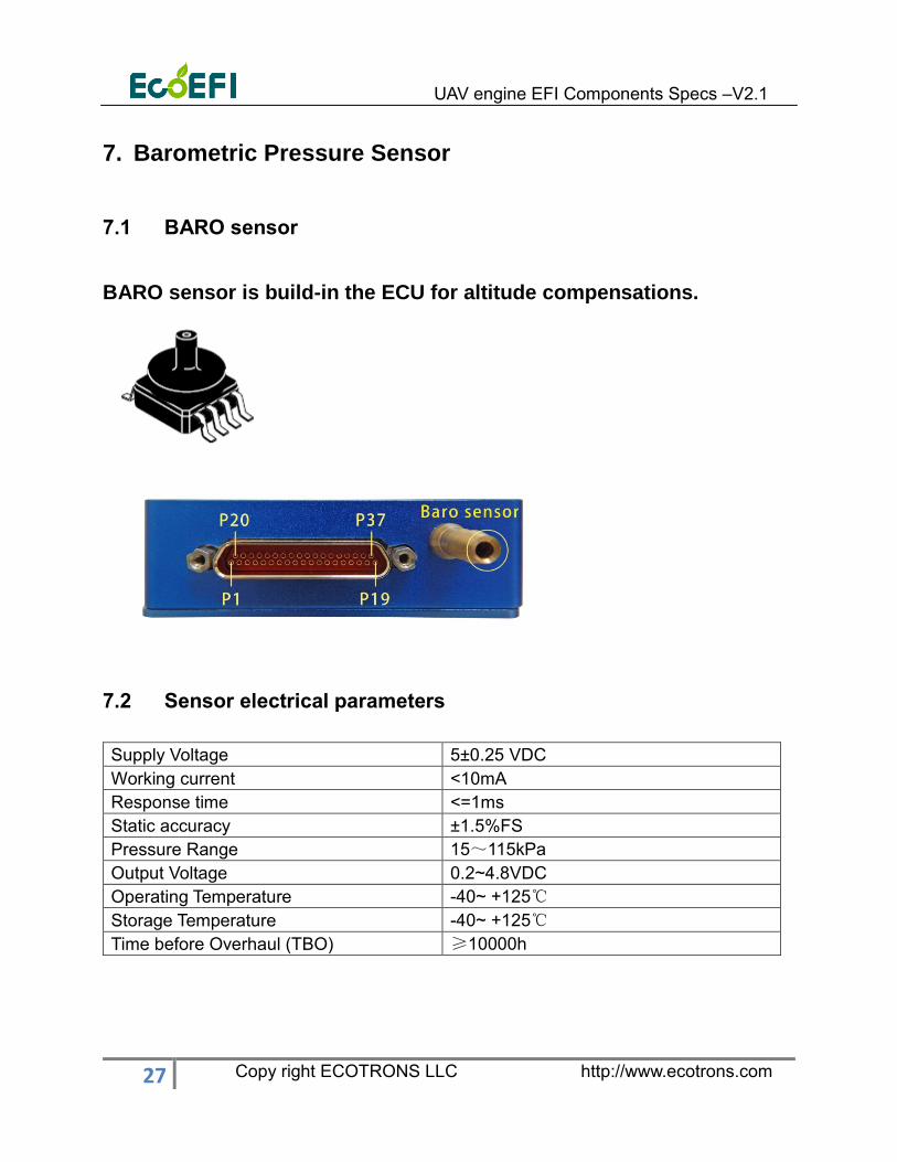
7. Barometric Pressure Sensor
7.1 BARO sensor
BARO sensor is build-in the ECU for altitude compensations.
7.2 Sensor electrical parameters
Supply Voltage 5±0.25 VDC
Working current <10mA
Response time <=1ms
Static accuracy ±1.5%FS
Pressure Range 15~115kPa
Output Voltage 0.2~4.8VDC
Operating Temperature -40~ +125℃
Storage Temperature -40~ +125℃
Time before Overhaul (TBO) ≥10000h

UAV engine EFI Components Specs –V2.1
28 Copy right ECOTRONS LLC http://www.ecotrons.com
8. Map Sensor (Optional for 4 stroke engine only)
8.1 Electrical connection
This MAP sensor requires a +5v power supply, and a ground return and has an
analog voltage output.
The sensor output is in 0-5v range. It is linear proportional to the pressure
measured.
The MAP sensor usually is used four stroke single cylinder UAV engine.
Pin1: Signal wire Output Blue
Pin2: Ground wire Ground White
Pin3: Power wire +5V Red
8.2 Sensor electrical parameters
Working current <10mA
Weight 10g
Response time <2ms
Static accuracy ±1.8%FS
Pressure Range 20~103kPa
Operating Temperature -40 oC ~ 120 oC
Compensated Temperature 0 oC ~ 80oC
Storage Temperature -40 ~ 130 oC
Max. Voltage 7 VDC
Supply Voltage 5±0.5 VDC
Output Voltage 0.5~4.9VDC
Pressure Port size 4mm hose (fuel resistant)
Overload Pressure 300kPaA
Output Type 0-5V
Pressure Cycles 30,000kms or more than one year
UAV engine EFI Components Specs –V2.1
29 Copy right ECOTRONS LLC http://www.ecotrons.com
Media Compatibility Air
Time before Overhaul (TBO) ≥5000h
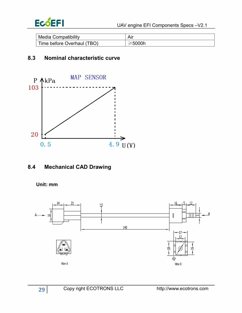
8.3 Nominal characteristic curve
8.4 Mechanical CAD Drawing
Unit: mm
UAV engine EFI Components Specs –V2.1
30 Copy right ECOTRONS LLC http://www.ecotrons.com
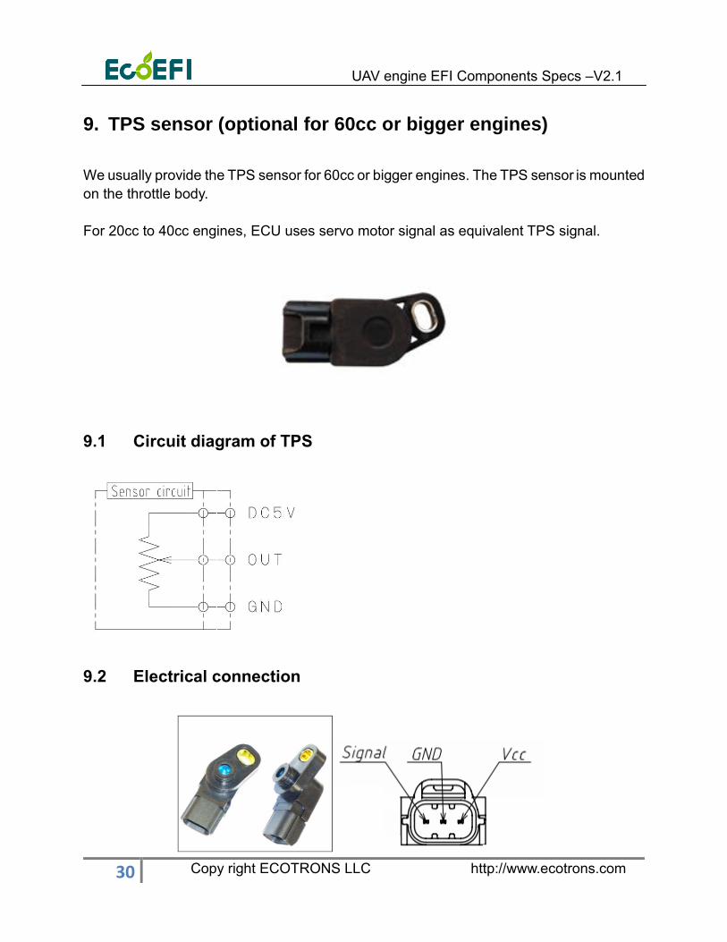
9. TPS sensor (optional for 60cc or bigger engines)
We usually provide the TPS sensor for 60cc or bigger engines. The TPS sensor is mounted
on the throttle body.
For 20cc to 40cc engines, ECU uses servo motor signal as equivalent TPS signal.
9.1 Circuit diagram of TPS
9.2 Electrical connection

UAV engine EFI Components Specs –V2.1
31 Copy right ECOTRONS LLC http://www.ecotrons.com
9.3 Output characteristics
9.4 Sensor specifications
1) Basic specifications
NO. Item Criteria
1 Electrical rotation angle 100°
2 Mechanical rotation angle 125°
3 supply voltage DC +5V
4 Storage temperature -40 oC --120 oC
5 Operating temperature -40 oC --120 oC
6 Total resistance 3kΩ±20%
7 Output Linearity ±2%
8 Installation torque 49.03 mN.m(MAX)
9 Weight 15g
2) Durability:
UAV engine EFI Components Specs –V2.1
32 Copy right ECOTRONS LLC http://www.ecotrons.com
10. Servo motor
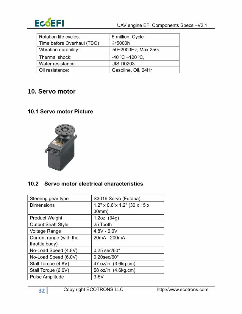
10.1 Servo motor Picture
10.2 Servo motor electrical characteristics
Steering gear type S3016 Servo (Futaba)
Dimensions 1.2" x 0.6"x 1.2" (30 x 15 x
30mm)
Product Weight 1.2oz. (34g)
Output Shaft Style 25 Tooth
Voltage Range 4.8V - 6.0V
Current range (with the
throttle body)
20mA - 200mA
No-Load Speed (4.8V) 0.25 sec/60°
No-Load Speed (6.0V) 0.20sec/60°
Stall Torque (4.8V) 47 oz/in. (3.6kg.cm)
Stall Torque (6.0V) 58 oz/in. (4.6kg.cm)
Pulse Amplitude 3-5V
Rotation life cycles: 5 million, Cycle
Time before Overhaul (TBO) ≥5000h
Vibration durability: 50~2000Hz, Max 25G
Thermal shock: -40 oC ~120 oC,
Water resistance JIS D0203
Oil resistance: Gasoline, Oil, 24Hr
UAV engine EFI Components Specs –V2.1
33 Copy right ECOTRONS LLC http://www.ecotrons.com
Operating Temperature -20 to +60°C
Continuous Rotation
Modifiable
Yes
Direction w/ Increasing
PWM Signal
Counter Clockwise
Motor Type 3-Pole Motor
Potentiometer Drive Indirect Drive
Output Shaft Support Ball Bearing
Gear Type Straight Cut Spear
Gear Material All Metal Gears
Wire Length 12" (3048mm)
Time before Overhaul(TBO) ≥200
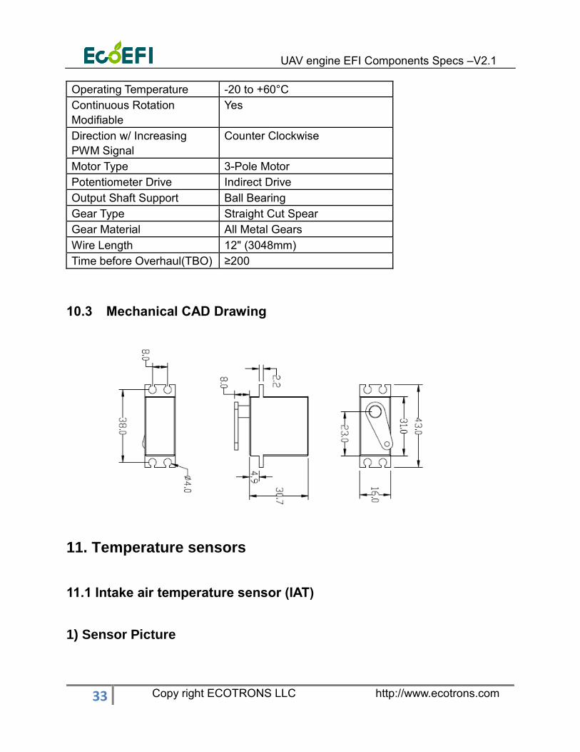
10.3 Mechanical CAD Drawing
11. Temperature sensors
11.1 Intake air temperature sensor (IAT)
1) Sensor Picture

UAV engine EFI Components Specs –V2.1
34 Copy right ECOTRONS LLC http://www.ecotrons.com
IAT sensor installation: it can be inserted into the air filter or installed in the air inlet
of manifold.
2) Sensor electrical characteristics
Zero power resistance R25=2KΩ+1% 25 oC
B-value B25/50=3470k±1%
Thermal time constant 7s max in static air
Dissipation constant 0.6mW/oC
~0.95mW/ oC
in static air
Power rating 3mW
Operating temperature range -40 oC ~150 oC
Storage temperature range 0~120 oC
Time before Overhaul (TBO) ≥43800h
Weight <=7g
3) Mechanical CAD Drawing
11.2 Engine temperature sensor
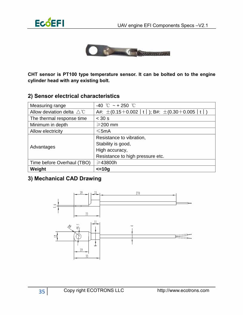
1) Cylinder Head Temperature Sensor Picture
UAV engine EFI Components Specs –V2.1
35 Copy right ECOTRONS LLC http://www.ecotrons.com
CHT sensor is PT100 type temperature sensor. It can be bolted on to the engine
cylinder head with any existing bolt.
2) Sensor electrical characteristics
Measuring range -40 ℃ ~ + 250 ℃
Allow deviation delta △℃ A#: ±(0.15+0.002│t│); B#: ±(0.30+0.005│t│)
The thermal response time < 30 s
Minimum in depth ≥200 mm
Allow electricity ≤5mA
Advantages
Resistance to vibration,
Stability is good,
High accuracy,
Resistance to high pressure etc.
Time before Overhaul (TBO) ≥43800h
Weight <=10g
3) Mechanical CAD Drawing
UAV engine EFI Components Specs –V2.1
36 Copy right ECOTRONS LLC http://www.ecotrons.com
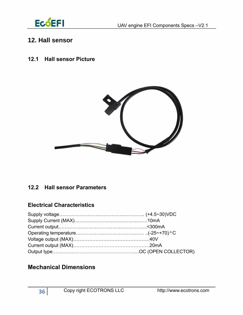
12. Hall sensor
12.1 Hall sensor Picture
12.2 Hall sensor Parameters
Electrical Characteristics
Supply voltage………………………………….………….. (+4.5~30)VDC
Supply Current (MAX)………………………………….……10mA
Current output………………………………………………..<300mA
Operating temperature……………………………………. ..(-25~+70) o C
Voltage output (MAX)…………………………………………40V
Current output (MAX)…………………………………………20mA
Output type……………………………………………....OC (OPEN COLLECTOR)
Mechanical Dimensions
UAV engine EFI Components Specs –V2.1
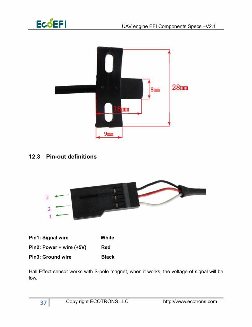
37 Copy right ECOTRONS LLC http://www.ecotrons.com
12.3 Pin-out definitions
Pin1: Signal wire White
Pin2: Power + wire (+5V) Red
Pin3: Ground wire Black
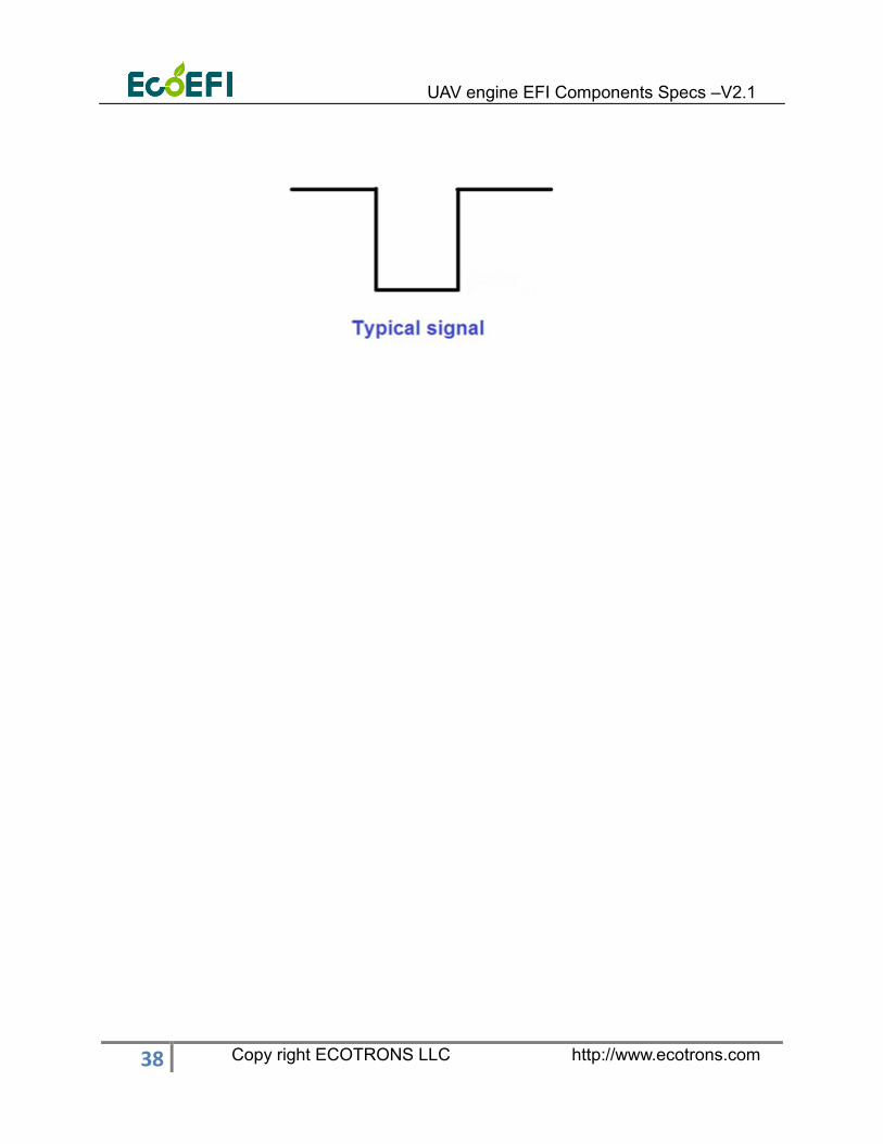
Hall Effect sensor works with S-pole magnet, when it works, the voltage of signal will be
low.
UAV engine EFI Components Specs –V2.1
38 Copy right ECOTRONS LLC http://www.ecotrons.com