uccnc software installation and user's guide - … · uccnc software installation and...
TRANSCRIPT

UCCNC software installation and user's guide
Version of this software manual: 1.0042Software version: 1.2047
Supported motion controllers:
● UC100 ● UC300ETH – 5LPT
● UC300 – 5LPT ● UC300ETH – M44
● UC300 – M44 ● UC300ETH - 5441
● UC300 - 5441 ● UC300ETH - M45
● UC400ETH ● UC300ETH - UB1
1/82

Contents
1.Installation of the software.1.1.Introduction1.2.Safety notes1.3.Hardware requirements1.4.Software prerequirements1.5.Download and install1.6.Licensing.1.7.The first run, first steps
1.7.1.Command line arguments2.The graphical user interface
2.1.The default screenset2.2.Screen elements
2.2.1.Tab pages2.2.2.Buttons2.2.3.Labels2.2.4.LEDs2.2.5.Toolpath viewer2.2.6.Jog control
2.3.Virtual mouse control.3.Setting up the software for the machine (Configuration)
3.1.Axis setup3.2.Spindle setup
3.2.1.Spindle pulleys3.2.2.Spindle PID controller
3.3.Auxiliary encoders3.4.I/O setup3.5.I/O trigger
3.5.1.Input trigger3.5.2.Output trigger3.5.3.Hotkeys
3.6.General settings3.7.Appearance3.8.Importers 3.9.Profiles
3.9.1.Operator (un)lock3.9.2.Statistics
3.10.Offsets3.11.Tools3.12.Diagnostics3.13.Porting the settings to a different computer
4.The code interpreter4.1. Supported codes
4.1.1.G-codes4.1.2.M-codes4.1.3.Other codes
4.2. Parametric programming4.2.1. Available math operators and operations
2/82

4.3. Using the software, executing codes, using functions4.3.1.Open, edit, close a G-code file4.3.2.Executing code from program4.3.3.Executing code via the MDI4.3.4.Zeroing and referencing one or more axis4.3.5.Using offsets4.3.6.Overriding the feedrate and the spindle speed4.3.7.Using the toolpath and G-code viewers4.3.8.Jog control, jogging the machine
5.Macro-ing capability
6.Plugin controls6.1.Installing plugins6.2.Enabling, configuring and using plugins6.3.Writing/creating custom plugins
7.Screen editor7.1.Description of the screen editor7.2.Editing screen elements7.3.Editing the canvas properties7.4.Editing picture images7.5.Saving the screen
8.Macro loops8.1.Description of macro loops8.2.Writing macros for loops8.3.Running, stopping, killing macro loops
1 .Installation of the software 1.1 .Introduction
For first of all we thank you for your interest in our software product and reading this user's guide.This first section of the manual will describe the basic purpose of this software and what hardware you will need and may need to you use it.
The UCCNC is a machine control software. It uses and external hardware to generate signals to produce coordinated motion on upto 6 machine axis. The external hardware is a motion controller device which is currently our UC100 or UC300 or UC400ETH motion controller.
This software connects to the external motion controller via a single USB port connection or ethernet connection (depends on the motion controller model) of a personal computer (PC) and via a software application interface (API) which is built into the software. The installer of the UCCNC software includes and completes all the tasks to make it possible to use this software on your computer. The device drivers are included in the installer too.
The UC100 motion controller and this software is not capable to run motors and machine axis directly, it is capable only to produce the required signals to run a machine like a CNC mill which requires programmed coordinated motions. The possibility and the selection on the external motor controller is nearly endless and there are lots of options and choices on the stepper and servo motor controller market. We also offering a few options and most of the 3rd party hardware available on the market today will also work. To get a more clear idea about how this software works and what else electronics you may need to get your machine running please read this user's guide further and make your own resource on the internet, there are lots of useful informations and articles available
3/82

about motion and motor control electronics.
1.2 .Safety notes
Moving objects like machine axis and machine parts can be dangerous and could cause personal injury or even death. Please keep this always in mind and operate your machine carefully keeping all safety standards and regulations first.
1.3 .Hardware requirements
This software requires Microsoft Windows XP, 7 , 8, 8.1 or 10 Operating System running on an x86or x64 desktop or laptop or tablet computer.
The minimal hardware requirements for the computer are as follows:– CPU frequency: minimum 1.8 GHz (duo or dual core is recommended.)– Graphics card: OpenGL 1.3 or higher compatible– RAM: minimum 1GB for XP and 2GB for all other supported OS.– Hard drive space: minimum 16GB
The above are the recommended minimal values, however the software may run on PCs with lowerrecources, but we do not advice to do so.If large G-code files with the hundreds of thousands or millions of code lines count are run then the requirements may be higher.We suggest to always try the software even in demo mode on the planned to be used computer with the largest and most complex planned to be run g-code files to see the performance and to see if the computer fits the software requirements.
1.4 .Software prerequirements
Prior to install the software the .NET framework 2.0 need to be installed. The .net framework 2.0 is Microsoft's runtime environment for applications (like the UCCNC) developed in Visual Studio.
On Windows XP operating system the .net framework 2.0 can be installed from a file which is available of Microsoft's website and we also keep a copy of this file on the following link: http://cncdrive.com/MC/Software%20prerequirements/dotnetfx2_0.exe
On Windows 7. the .Net framework 2.0 is part of the Operating system, no need to install it.
On Windows 8.,8.1 and 10 the .Net framework can't be istalled from file, it can be installed with enabling the .Net 3.5 compatibility option in Windows and then it installs automaticly via the Windows update. The .Net framework 3.5 package contains the .Net 2.0 package too.
If the .Net framework is not installed, the UCCNC software installer will not run, it will drop an error message on startup and the installer will exit. On Windows 10. no error message will be shown, but the installer will not run without the .Net framework 3.5 installed.
1.5 .Download and install
The UCCNC software comes in a single .exe executable installer package, the uptodate version is always available as a download on our website: http://www.cncdrive.com/UCCNC/download_UCCNC.php
4/82

Download the setup.exe file from the above link, save it to your harddrive and double click the file to start the installation process.When running the setup file the following screen will pop up:
Press the next button to proceed the installation.
The End-User License Agreement for the software will appear and you should read the EULA carefully and if you agree the terms select the "I accept the agreement" radiobutton and press the next key. If you do not accept the EULA then press the cancel button and in this case the installationwill terminate.
5/82

On this screen the installation folder path can be set, The default installation location is your main harddrive which is mostly the C: drive and the \UCCNC folder. The path can be changed with overwriting the path string on this window. Before pressing the next button make sure that there is enough disk space available on the harddrive used for the installation, the required disk space is indicated on this window. When these are done press the next button.
If the software was installed previously to the same directory then the installer will ask for permission to overwrite the previously installed software version and the files.Select yet to proceed the installation.
6/82

There is an option to overwrite or keep the previously installed default profile file. The default profile file contains all the settings of the screen, machine settings etc.It is strongly recommended to select this option.
The installer will ask under what section name to create a shortcut icon for the software in the startup menu in Windows. The default is CNCdrive\UCCNC software. Press next to proceed the installation.
7/82

Finally before the actual installation process starts a summary screen will appear where you can check the settings you made. This is the last time the installation can be rolled back with pressing the back button.To confirm the settings and start the installation process press next.
8/82

The installation starts and the installer extracting and copying all files and registry entries as nessessary. Wait while the process finishes, it may take a few minutes.At the end of the installation process you will be asked to plug the UC100 device to the computer's USB port, do so.
Because the USB drivers were preinstalled by the installer Windows will automaticly assign the USB drivers to the device once it gets plugged to the PC's USB port.Wait while the process finishes and press the next button.
The installation got finished and selecting the "Run UCCNC.exe" option will start the software when pressing the Finish button. Press the finish button to exit the installer.
1.6 .Licensing.
The software requires a license key to fully function. The license key is an encrypted file releasedby the author and owner of the software: CNCdrive Kft. company. One license key is valid and canbe used with one UC100 device only. The license keys are personalised and assigned to an UC100or other future motion controller device's serial number which makes the software function withthat specific device only.
9/82

The UC100 device's serial number and the license key's serial number must match, the license keywith one serial number and an UC100 device with a different serial number will not work.A separate license key should be purchased for each UC100 devices for the UCCNC software towork with them. It also must be noted that the software can connect to and can run with one UC100device one time. The license key file is delivered in e-mail only, no physical media (CD/DVD) issupplied.
To install the license key, simply copy the license key file to the UCCNC installation folder and runthe software. The software automaticaly senses the license key in the installation directory and willconnect to the device.
Without a license key the software runs in demo mode when there is no physical connection is madeto the external motion controller, the software emulates the motion, but signals are not generated bythe device.
Without an UC100 device connected or installed to the computer the software will start in demomode. As mentioned previously in this case the software emulates the motion, but no signals aregenerated by the device, all motions happening on the screen is just simulation.
The possiblity of using the software in demo mode without a software license key and withoutbuying an UC100 motion controller provides the ability for you to try and test the software withoutthe need of any prior purchase. We recommend that you test and make sure that the software fitsyour needs before purchasing a software license key.
Software license keys because of the nature of this kind of product are not returnable and are notrefundable.The following printscreen picture shows the software running in demo mode, please note the "Running in demo mode..." text in the header of the window.
10/82

1.7 .The first run, first steps.
After the installation process and licensing the software it is time to run and setup the software towork with your machine.To run the software double click the UCCNC icon on the desktop or in the start menu.If only a single UC100 or UC300-5LPT device is connected and if the software is licensed for thatdevice then the software will startup.If no devices are connected or if more then one devices are connected or if one device is onlyconnected but it is not licensed for the software then the following device selection window willpopup prior to the software startup:
The device selection window lists all the available motion control devices which are actuallycunnected to the PC and also it lists the available demo modes to run the software in. The devices
11/82

can be selected with clicking and then with pressing the Continue button the software will startupand will connect to the selected device in case that device is licensed. If the selected device is notlicensed then the software will run in demo mode simulating the selected device.Selecting any of the demo modes will also simulate the device.
1.7.1 .Command line arguments
Command line arguments can be used to influence how the software starts. The arguments may be written to the shortcut icon properties target field after the path of theUCCNC.exe file.The available command line arguments are as follows:
– /n : Using this switch in the argument will only allow the software to start one instance. Ifone instance is already running, the software will show an error message and will close.
– /p profilename : Using this switch forces the software to load a specific machine profile file.– /s serialnumber : Using this switch forces the software to connect to a motion controller with
the specified serial number. If the motion controller is not connected (not available) or if it isalready in use then the software will show an error message and will close.
– /d devicetype : Using this switch forces the software to always run in demo mode only, nomatter if any motion controller devices are connected. The devicetype parameter can haveone of the following values: UC100, UC300_5LPT, UC300_ISOBOB, UC300_M44, UC300_5441, UC300_HI, UC300_LOW, UC300ETH_5LPT, UC300ETH_5441, UC300ETH_HI, UC300ETH_LOW, UC300ETH_M44, UC300ETH_M45, UC300ETH_ISOBOB, UC400ETH
And example for using the command line arguments:
C:/UCCNC/UCCNC.exe /p myprofile /s 60CC4D
This comamnd will load the myprofile profile file (myprofile.pro) and will connect only to thedevice with the 60CC4D serial number.
2 .The graphical user interface
The graphical user interface (GUI) is based on OpenGL technology. All screen components like the buttons, labels, TAB layers are customisable, the look, format ofthese elements are defined in a screen set script file. The UCCNC software loads the screen setscript on startup. The name of the screen set file is defined in the Profile file in the"mainscreenfilename" key entry. Changing this key entry value will read a different .ssf screensetfile. The user could write their own screen set file customizing the GUI and it's components.
The screen can be dinamicly resized on the fly and the form elements resizing accordingly, thismakes the usage ideal on monitors with any screen resolutions.
2.1 .The default screenset
The default screenset is the screen set file (.ssf) which the software installs by default.This screenset file contains components and graphics for a 6-axis machine controller.Printscreens of this screenset are shown in this documentation.
2.2 .Screen elements 2.2.1 .Tab pages
12/82

Tab pages are similar to the standard Windows TAB control pages. These elements are like layerson the screen. Clicking the label text of the TAB page changes the screen view and showing thecomponents on the selected TAB layer. TAB layers can have a hierarchy where any TAB layer canhave child TAB layers and all TAB layers have a parent layer. The basic layer is layer 1. which isthe main and lowest layer on the screen, in other words this layer is the UCCNC window itself.Any number of tab pages with any labels can be placed onto the screen when making a customscreen set file. The way of placing TAB controls on the screen will be further discussed in aseparate documentation which will be about writing own screen sets.
The TAB pages on the default screen set are:
– Run
This page is the main page of the screen, it contains the buttons to load, edit, run, close a G-codefile. It also contains buttons to switch the spidle, coolant, mist on/off, select the offset coordinatesystem. It contains a 3D toolpath viewer and a G-code viewer. On the top of the screen the 6 axisposition DROs and actual and set feedrate, spindle set rotational speed and spindle actual rotationalspeed DROs are taking place. An MDI (manual data input field) is placed on the middle of thescreen, this component allows a manual G-code input via the keyboard.
– Toolpath
This page is to get a more clear view of the toolpath loaded into software. The page contains a large,high resolution 3D toolpath viewer and buttons to navigate, zoom and to have different viewingangles of the toolpath.
– Offsets
This page contains the offset coordinate system parameters. The offset coordinate systems are on 6sub TAB pages and are G54, G55, G56, G57, G58, G59 respectively. The actual offset coordinatesystem can be selected on the Run page. The offset values on the actually selected offset system isapplied to the coordinate DROs of the machine and the name of the actual offset system is indicatedin a label on this screen for example "Active fixture: G54" means that the G54 coordinate system isselected. Currently work offset is available for all the 6 axis and in addition a tool offset is availablefor the Z-axis. The offset numeric values are one by one all editable on the screen.
The current position which is the actual position of the machine can be offset with a single buttonpress. Also the work offset can be cleared with one button and the tool offset can be cleared in asimilar way with a single button press.
– Tools
This page contains the tool offsets for the Z-axis, because as previously described tool offsets are currently only available for the Z-axis only.There are in total 96 pieces of tool offsets are available marked Tool#1 to Tool#96 on the screen.All tools can have it's own tool length offset value. All tools numeric values are editable on the screen and the values can be saved to the profile file.
– Configuration
This page is the most complex tab page, it contains several sub TAB pages and this page has all the software configuration parameters. The sub tab pages and their purpose will be discussed in the
13/82

followings.
– Axis setup (sub tab page)
This page has sub pages for all 6-axis settings X, Y, Z, A, B, C axis respectively.The axis settings can be made on these tab pages.There is also a sub tab page for the Spindle settings.
– I/O setup (sub tab page)
This page contains the input and output pins definitions, settings for the E-stop, charge pump and other signals which are not exact relations with the axis and the spindle.
– General settings (sub tab page)
This page contains the parameters for the USB communication and some machine behaviour.
– Appearance (sub tab page)
This page contains settings for the toolpath viewer screen colors.
– Importers (sub tab page)
This page contains data import function(s).
– Profiles (sub tab page)
This page contains the machine profile setup, profiles can be loaded, created, deleted.
– Diagnostics tab page
This page shows datas and feedback about the current job and the machine properties, like I/O and functions logic states.
– Help tap page
This page lists the supported G and M and other codes with basic descriptions. Also the motion controller device parameters and the license key validity can be read here.
2.2.2 .Buttons
Buttons are one of the most important screen elements, these are like Windows buttons, pressing them execute an action. All buttons have a function to call inside the UCCNC software. All these functions have a pre-defined identify number. When creating a screen set file the buttons can be defined to call one of these functions by adding the function number to the button by a parameter.The function numbers of the different buttons and how to add them to a custom screen will be defined in a separated documentation which will be about writing a custom screen set file.
To read more about the buttons controls read the Buttons_by_number.htm document.
14/82

2.2.3 .Labels
Labels are used to show texts on the screen and also they are used to input values from the user. Labels can be static labels which are not updateable, their contant is constant and always the same.Static labels does not have a reference number since they never need an update of their value, their content is static, always the same. The text content of these buttons are defined in the screenset script and uploaded to the screen when the software load the screenset.There are also output and input type dynamic labels. Dynamic labels are updated by the software mostly in sequence or in case an event is happening. Dynamic labels all have a reference/function number. There are input and output type dynamic labels. The output type labels are to view only text while the input type labels are used to input datas from the user via the screen.
To read more about the labels controls read the Labels_by_number.htm document.
2.2.4 .LEDs
LED controls are used to show the state of Boolean variables states to the user. Leds can have 2 states on/off and the actual state of each LEDs is updated by the software automaticly.Every LED function have a function number which means the variable the LED will indicate.
To read more about the LED controls read the LEDs_by_number.htm document.
2.2.5 .Toolpath viewer
The toolpath viewer is a special control which is used to show, visualise the path the machine will execute for the loaded G-code program. Each tab page can have one toolpath viewer control.There are several associated buttons functions which can show the toolpath from different view points, angles, zoom the contents, zoom in and out etc. To read more about these read the Buttons_by_number.htm document and look for the associated buttons controls.
2.2.6 .Jog control
The jog control panel is located at the right side of the window and is used to move the machine is manual, "jog" mode.
2.3 .Virtual mouse control
There can be machine controls where no physical mouse or trackball is installed. In these system it is still possible to control the mouse cursor with keyboard keys using the virtual mouse function.To enable the virtual mouse control press the TAB keyboard key and this will enable the virtual mouse control mode. The indication of the virtual mouse control is enabled is that the mouse pointer changes from the arrow to a cross icon. In virtual mouse control mode the mouse cursor can be moved left/rigth and up/down with the keyboad arrow keys and the left mouse click can be emulated with pressing the enter key on the keyboard. The cursor can be moved with high speed if the Shift keyboard key is pressed and is held down while the cursor is commanded to move with the arrow keys.To disable the virtual mouse control press the TAB keyboard key again and the mouse cursor will change back to the arrow icon and the function is then disabled.
3 .Setting up the software for the machine (Configuration)
15/82

3.1 .Axis setup
The machine axis settings can be configured in the axis setup.The axis setup page contains 6 sub tab pages for the 6 available axis.All axis has identical settings, except that the X,Y and Z axis can have a slave axis, so these axishave an additional setting for the slave axis selection.Each axis has the following settings:
Step port & pin: Which is the physical output pin on the UC100 device for the step signal. Thesignal can be configured active low or active high selecting or unselecting a checkbox next to thecontrol.The active high means that the rising edge (0->5Volts) is the active edge of the step signal andactive low means that the falling edge (5->0Volts) is the active edge of the step signal.
Dir port & pin: Which is the physical output pin on the UC100 device for the step signal. Thesignal can be configured active low or active high selecting or unselecting a checkbox next to thefield. Changing the active polarity of the signal reverses the axis running direction.
Enable port port & pin: Which is the physical output pin on the UC100 or UC300 device for theenable signal. Which is the physical output pin on the UC100 device for the step signal. The signalcan be configured active low or active high selecting or unselecting a checkbox next to the field.The enable signal goes active when the axis is enabled with the "Axis enabled" checkbox markedand when the software is out of reset. Otherwise the enable signal is inactive.
Limit – and + port & pins: These are the physical input pins on the UC100 device for the limitswitches.Limit switches are used to limit the workspace, limit the length of an axis or in other words to not
16/82

allow the machine to run over a certain position on each axis direction.When the limit switch is activated the UCCNC software triggers the reset signal and stops themotion. The signal can be configured active low or active high polarity. The correct polaritydepends on if the limit switch or sensor inputs a low (0V) or high (5V) signal when activated.One negative and one positive side of limit pins can be defined.The limit pins may be the same for more than one axis. Any combination of the limit pins for anyaxis is allowed. To disable a limit input pin, write 0 value to the field.
Home port & pin: Which is the physical input pin on the UC100 device for the Home of Referencepoint switch or sensor. The machine axis can be homed and pick up the reference point using thisswitch or sensor. The signal can be configured active low or active high polarity. The correctpolarity depends on if the Home switch or sensor inputs a low (0V) or high (5V) signal whenactivated.The home direction to the positive or to the negative side of the axis can be configured with the"Direction positive" checkbox.The home pin may be the same pin as a limit pin, if using the same sensor for the home and limitfunctions. If the home and limit pins are the same then the pin will be treated as a limit pin all thetime except when a homing sequence for that axis is in execution. In this case the lmit function isdisabled and the pin is treated as if it was a home switch only. When the homing sequence isfinished, the pin is again treated as a limit input pin.
Homing speed up: Which is a numeric value and sets the feedrate of the motion when homing theaxis and when the axis is moving to the home sensor.The Homing feedrate can be equal or lower than the Velocity parameter of the axis.The parameter is defined in Units per minute.
Homing speed down: Which is a numeric value and sets the feedrate of the motion when homingthe axis and when the axis is moving down from the home sensor.The Homing feedrate can be equal or lower than the Velocity parameter of the axis.The parameter is defined in Units per minute.
Write offset on Homing: Which is a numeric value and sets the coordinate to write to the axisposition DRO when a homing action is executed and succeded.The parameter is defined in Units.The homing position DRO value can be autoset with checking the checkbox next to the field.If the autoset checkbox is not set then the axis will remain it's coordinate when a homing sequenceis successfully executed. If the autoset checkbox is not set then the set value will be written to theaxis position DRO when a homing sequence is successfully executed.
Steps per Units: Which is a numeric value and means the output pulses per one Unit of mechanicaltravel on the machine axis. The correct value depends on the resolution of the motor and motordrive in case a stepper motor and drive is used or on the encoder resolution if a servo motor anddrive is used to drive the axis.
Velocity: Which is a numeric value and sets the maximum feedrate on the axis. The axis cannot runon higher feedrate then the set value. In G0 (rapid linear motion) code execution the motion isexecuted with this feedrate value.The value of this parameter is in Units/minute.
Acceleration: Which is a numeric value and sets the maximum acceleration value of the axis. Theaxis cannot accelerate faster than the set value.The value of this parameter is in Units/sec/sec.
17/82

Softlimit - : Which is a numeric value and is the negative direction software position limit. The axiscannot run to a lower coordinate than the set value. Note: The software limits can be enabled ordisabled on the general config tab page with checking or unchecking the enable softlimitscheckbox.The value of this parameter is in Units.
Softlimit + : Which is a numeric value and is the positive direction software position limit. The axiscannot run to a higher coordinate than the set value. Note: The software limits can be enabled ordisabled on the general config tab page with checking or unchecking the 'enable softlimits'checkbox.The value of this parameter is in Units.
Backlash distance: Which is a numeric value and sets the backlash distance to compensate on theaxis. The backlash compensation can be enabled or disabled with checking or unchecking the'enable backlash' checkbox next to the textfield. The value of this parameter is in Units.
Compensation acceleration: Which is a numeric value and defines the acceleration of the axiswhen compensating the backlash and also used when rigid tapping (G33.1 and G33.2) and whenthread cutting (G33 and G76). This value has to be set at least 20% higher than the accelerationparameter of the axis.The value of this parameter is in Units/sec/sec.
Slave axis: This setting is only available for the X, Y and Z axis. These axis can have a slave axisattached to them. The slave axis moves together with the master axis. The slave axis can be the A, Bor the C axis. The slave axis functionality is useful for example in router machines where 2separated motors running the same axis on the 2 sides of the gantry axis. These motors can setup asa master and slave axis, so the two axis will run together in syncron.
Calibrate button: Each axis setup page has a calibrate button. Use this button to calibrate theresolution (steps per value) on the axis. Pressing this button will open an axis calibration windowwhich looks the following:
18/82

The calibration is built from a 3 steps sequence. Press the OK button to process the sequences.The first step of the sequence moves the axis to the set distance with the set feedrate using thecurrently set steps per unit value. The next step is to measure the distance on the machine axisbetween the movement startpoint and the movement endpoint and type the measured distance valueback to the screen. In the third seqeunce the software calculates the new steps per value based onthe previous and the measured input data. The new steps per value is shown on the page and againpress OK to save the new value and to end the calibration process. A new calibration process can be started with pressing the OK button again, or the process can beterminated and the window can be closed pressing the cancel button any time.
3.2 .Spindle setup
The spindle setup tab page contains settings for the main spindle of the machine.The spindle can be a spindle with PWM (analog input) control or a step/dircetion control spindle.Separate relays can be also setup to switch the spindle on/off.The mist and flood coolant control parameters setup are also located on this tab page, because theseare in close relation to the spindle control.
19/82

The spindle setup tab page has the following parameters:
Settings for a PWM control type spindle:
PWM spindle check box: Selecting this checkbox sets the spindle to PWM control mode. In PWMcontrol the spindle control signal is a PWM (pulse width modulation) signal and the PWM dutycycle is changed proportionally with the programmed spindle speed.The PWM spindle control mode is useful for analog input spindle electronics forexample forVariable Frequncy Drives with analog input. The PWM signal can be filtered, smoothed to ananalog signal using a simple RC (resistor + capacitor) network.
PWM port & pin: This is the physical output pin number for the spindle control PWM signal, thesignal will appear on the selected pin. The signal can be inverted setting the 'active low' checkboxnext to the textfield.
Dir port & pin: This is a physical output pin number of the spindle direction signal. The runningdirection of the spindle depends on if an M3 (Clockwise rotation) or M4 (Counter clockwiserotation) is programmed. The direction signal changes according to the programmed runningdirection. The signal can be active low or high. Changing the direction active state inverts the signalpolarity.
PWM frequency: This parameter sets the base frequency of the PWM signal, in other words it setshow long one PWM cycle will last. The time perion of the PWM cycle equals 1/PWM frequency.The value of this parameter is in Hertz.
PWM min duty (%): This parameter sets the minimum duty cycle of the spindle speed PWMsignal. The PWM duty cycle will go to this level when the lowest spindle speed is set.
20/82

PWM max duty (%): This parameter sets the maximum duty cycle of the spindle speed PWMsignal. The PWM duty cycle will go to this level when the highest spindle speed is set.
Settings for a step/direction control type spindle:
Step/direction spindle checkbox: Selecting this checkbox sets the spindle to step and directioncontrol mode. In step and direction control the spindle control signal is a step pulse train just like itis on the machine axis. This control mode is useful for position control spindles like servo motorspindles.
Step port & pin: This is the physical output pin number for the spindle control step signal, thesignal will appear on the selected pin. The signal can be inverted setting the 'active low' checkboxnext to the textfield.
Dir port & pin: This is a physical output pin number of the spindle direction signal. The runningdirection of the spindle depends on if an M3 (Clockwise rotation) or M4 (Counter clockwiserotation) is programmed. The direction signal changes according to the programmed runningdirection. The signal can be active low or high. Changing the direction active state inverts the signalpolarity.
Steps per rotation: This is a numeric value which represents the number of pulses the controllershould send out on the step signal to produce one full motor rotation.
Acceleration: This is a numeric value and sets the maximum acceleration for the spindle.The spindle cannot accelerate faster than the set value.The value of this parameter is in Rotation/sec/sec.
The following settings are shared between and valid for both a PWM and step/direction typespindle:
Minimum velocity: This is a numeric value and defines the programmable minimum rotationalspeed for the spindle motor. The spindle can be programmed with the 'S' parameter. If a lower thanthe minimum set value is programmed then the minimum setup value is used.
Maximum velocity: This is a numeric value and defines the programmable maximum rotationalspeed for the spindle motor. The spindle can be programmed with the 'S' parameter. If a higher thanthe maximum set value is programmed then the maximum setup value is used.
Index port & pin: This is a physical input pin for the index input signal. The index input signal isused to measure the spindle rotational speed and to feed it back to the actual spindle speed DRO.The index pin is also the index channel of the spindle feedback encoder for thread cutting.
Index prescaler: This is a numeric value and is used to divide the frequency of the spindlerotational speed. In other words this should be set to a value of 1 if a single slot spindle speedsensor is used and a a value of 2 if a dual slot spindle speed sensor is user and so on.
Encoder PPR: This is a numeric value and defines the pulse per revolution of the incrementalencoder which is used to feedback the spindle position in sycnronous thread cutting applications.
Reverse enc.dir: This parameter changes the encoder count direction. If the encoder pins wereaccidentally connected up in reverse then no need to exchange them or to change the A with B pin,just change this parameter to change the count direction of the encoder.
Encoder A port & pin: This is the physical input pin for the encoder A channel.
21/82

Encoder B port & pin: This is the physical input pin for the encoder B channel.
Spindle relay outputs enabled checkbox: Selecting this checkbox enables the M3 (rotation CW)and M4 (rotation CCW) relay outputs. These output activates when an M3 or an M4 code isprogrammed and the outputs can be used to switch the spindle on/off. Only one of these outputs canbe active one time. Both outputs can bedeactivated with programming an M5 command.
M3 spindle relay port & pin: This is a physical output pin for the spindle M3 (CW) relay. The pincan be inverted checking the active low checkbox next to the textfield. The pin is active when a M3command is programmed and inactive after a M5 command is programmed.
M4 spindle relay port & pin: This is a physical output pin for the spindle M4 (CCW) relay. Thepin can be inverted checking the active low checkbox next to the textfield. The pin is active when aM4 command is programmed and inactive after a M5 command is programmed.
M3 delay after on: This is a numeric value. The software dwells for the set amount of time inmilliseconds when a spindle M3 command is programmed and after the spindle output goes active.
M3 delay after off: This is a numeric value. The software dwells for the set amount of time inmilliseconds if the spindle M3 command was active and when a spindle M5 command isprogrammed and after the spindle output goes inactive.
M4 delay after on: This is a numeric value. The software dwells for the set amount of time inmilliseconds when a spindle M4 command is programmed and after the spindle output goes active.
M4 delay after off: This is a numeric value. The software dwells for the set amount of time inmilliseconds if the spindle M4 command was active and when a spindle M5 command isprogrammed and after the spindle output goes inactive.
Flood/Mist relay outputs enabled checkbox: Selecting this checkbox enables the M7 (Mist) andM8 (Flood) relay outputs. These output activates when an M7 or an M8 code is programmed andthe outputs can be used to switch the Mist and Flood coolants. Both outputs can be activated thesame time and both outputs can be deactivated with the M9 command.
M7 mist relay port & pin: This is a physical output pin for the spindle M7 (Mist) relay. The pincan be inverted checking the active low checkbox next to the textfield. The pin is active when a M7command is programmed and inactive after a M9 command is programmed.
M8 flood relay port & pin: This is a physical output pin for the spindle M8 (Flood) relay. The pincan be inverted checking the active low checkbox next to the textfield. The pin is active when a M8command is programmed and inactive after a M9 command is programmed.
M7 delay after on: This is a numeric value. The software dwells for the set amount of time inmilliseconds when a M7 command is programmed and after the Mist output goes active.
M8 delay after on: This is a numeric value. The software dwells for the set amount of time inmilliseconds when a M8 command is programmed and after the Flood output goes active.
M9 delay: This is a numeric value. The software dwells for the set amount of time in millisecondsif the M7 and/or the M8 command was active and after these outputs goes inactive.
22/82

3.2.1 .Spindle pulleys
The spindle pulleys settings can be useful for machines which have pulleys on between the spindleand the driving motor. These pulleys with different mechanical ratios can vary the speed range ofthe spindle and also the spindle feedback speed if the spindle Index sensor which measures thespeed is placed on the motor and not on the spindle.The spindle pulleys settings can be accessed with pressing the Spindle pulleys button on the Spindletab page and can be enabled with checking the Use pulleys checkbox next to the button.On the spindle pulleys Window there are 15 available slots to setup with different spindle speedranges and ratios.When the use pulleys checkbox is set then the pulley number can be selected with the M215 Pxcommand, where the P parameter means the pulley number to be used, for example M215 P1selects pulley number 1.The minimum and maximum speed value for the pulley defines what value the software will acceptwhen programming the spindle speed with the S word.The software automatically adjusts the spindle speed range to the setup PWM minimum andmaximum values when a PWM spindle is selected and it automatically adjusts the speed range tothe spindle step frequency if a Step/dir spindle is configured.The ratio parameter in the spindle pulleys settings scales the feedback with multiplying themeasured spindle speed with the ratio value before showing the measured value in the Sact Spindlespeed DRO.
If the use pulleys checkbox is not set then the pulley window settings are not used and the spindlespeed range used will be the value range setup on the main Spindle settings tab page and the ratioused for the feedback will be value 1.
The following page shows the Spindle pulleys settings window:
23/82
3.2.2 .Spindle PID controller
The spindle PID controller function is is only available with our ethernet motion controllers(UC400ETH and UC300ETH), this functionality is not available with our USB controllers (UC100and UC300).The function is accessible with pressing the Set button next to the Spindle PID control text.
The PID controller makes the spindle control closed loop.If the spindle speed drops then the controller adjusts the output signal to compensate and control thespindle speed to keep the programmed spindle speed value.The controller takes the programmed S parameter (Sset) as the control signal and the spindle speedmeasurement (Sact) as the feedback signal.A speed error signal is calculated using the Error = Sset - Sact.The error signal is fed to the PID controller input and a calculation is made to get an output signalwhich signal controls the spindle motor.The output signal is the setup PWM and/or analog output which are defined in the spindle setup.
For the spindle PID control to work the followings are required:
- The spindle speed has to be controllable with the output PWM or analog output signal.- An incremental encoder with A and B channels has to be connected and measure the spindle speedand the encoder resolution has to be configured.(Note: Single Index channel feedback is currently not supported, only an incremental encoder canbe used.)
The PID parameters are the followings:Kp: Proportional GainKd: Differential GainKi: Integrap GainSampling time: The repeat time interval in milliseconds of the PID calculation.
24/82

The following printscreen shows the spindle PID controller setup window:
3.3 .Auxiliary encoders
The auxiliary encoders menu and function is only available with our ethernet motion controllers(UC400ETH and UC300ETH), this functionality is not available with our USB controllers (UC100and UC300).The auxiliary encoders page contains 6 pieces of freely configurable incremental encoder counters.The encoders must be incremental type ones with A and B channel output signals.The encoders' positions can be read and written through the screenset with reading and writing theTextfields of the encoder coordinates. The Textfields can be read and written by GUI input and viamacros and plugins.With the 'Counts per' parameter the counts per the encoder ticks can be defined, so the encodercounting can be scaled up or down as required.The aux encoders can't be used to close the position loop of the axes, they could be used to verifyposition or for other custom purposes which requires encoder counters.
25/82

The following printscreen shows the auxiliary encoders tab page:
3.4 .I/O setup
The I/O setup tab page contains settings for in and output functions which are not in exact relationto the axis. These are the E-stop, probe, index inputs, charge pump, current hi/low output settings.
26/82

The I/O setup tab page has the following parameters for the UC100 device:
The I/O setup tab page has the following parameters for the UC300 device:
27/82

E-stop port & pin: This is a physical input pin for the e-stop button input signal. The pin can beinverted checking the active low checkbox next to the textfield. The machine goes to reset whenthis input signal is active.
Probe port & pin: This is a physical input pin for the straight probe input signal. The pin can beinverted checking the active low checkbox next to the textfield. The straight probe can beprogrammed with a G31 code.
Charge pump port & pin: This is a physical output pin for the charge pump safety output signal.The charge pump safety is a PWM signal. The pin can be inverted checking the active lowcheckbox next to the textfield. The PWM has a fixed 12.50kHz carrier frequency.If the 'charge pump always on' checkbox is set then the PWM signal is always on when the UCCNCsoftware is running. If the 'charge pump always on" checkbox is not set then the PWM signal isonly active if the software is not in reset and inactive if in reset.The charge pump signal can be used to enable an external electronics only if the UCCNC softwareis loaded or if it is not in reset making the operation of the electronics safe.
Current high/low port & pin: This is a physical output pin which can be used as an enable signalfor the external motor control electronics connected to the system. The pin can be inverted checkingthe active low checkbox next to the textfield. The signal is active if the software is running.
The following parameters are available for the UC300 only, because the UC100 has no analogsignals:
Analog input 1-> #var: This setting makes the software to load the analog input 1. channel's readvalue to the internal variable number set in this field. The software continously reading the analoginput and loading it into the variable. The value of the analog input is represented on 16bits, so thevalue can be between 0 and 65535, however the analog channel of the UC300's DSP has 12 bitsresolution only, therefor the read value is multiplied to 16bits and transferred to the software.To disable this function write 0 to this field.The variables can be used in G-code execution or to read out the value in MDI command: ?#variable number.
Analog input 2-> #var: This setting makes the software to load the analog input 2. channel's readvalue to the internal variable number set in this field. The software continously reading the analoginput and loading it into the variable. The value of the analog input is represented on 16bits, so thevalue can be between 0 and 65535, however the analog channel of the UC300's DSP has 12 bitsresolution only, therefor the read value is multiplied to 16bits and transferred to the software.To disable this function write 0 to this field.The variables can be used in G-code execution or to read out the value in MDI command: ?#variable number.
FRO analog channel: This setting attaches the feedrate override (FRO) to the selected analog inputchannel. Using this function the FRO can be set with an external potentiometer connected to theanalog input. The min.% value means the FRO percentage, which is set when 0Volts applied to theanalog input and the max.% value sets the maximum FRO percentage, which is when the analoginput has the maximum 10Volts input Voltage. Setting the min% to 0 value and turning thepotentiometer down to 0Volts sets the feedrate override to 0% which causes a feedhold till thepotentiometer is turned up again to higher than 0Volts.Setting the min.% value lower than the max.% value reverses the function, in this case the 10Voltsinput Voltage applies the min% value for the FRO and the 0Volts input applies the max.% value.This reversible operation makes it possible to use the potentiometer even if it was connectedbackwards to the power supply Voltage.
28/82

SRO analog channel: This setting attaches the spindle rate override (SRO) to the selected analoginput channel. Using this function the SRO can be set with an external potentiometer connected tothe analog input. The min.% value means the SRO percentage, which is set when 0Volts applied tothe analog input and the max.% value sets the maximum SRO percentage, which is when the analoginput has the maximum 10Volts input Voltage. Setting the min.% value lower than the max.% value reverses the function, in this case the 10Voltsinput Voltage applies the min% value for the SRO and the 0Volts input applies the max.% value.This reversible operation makes it possible to use the potentiometer even if it was connectedbackwards to the power supply Voltage.
JRO analog channel: This setting attaches the jog rate override (JRO) to the selected analog inputchannel. Using this function the JRO can be set with an external potentiometer connected to theanalog input. The min.% value means the minimum JRO percentage, which is set when 0Voltsapplied to the analog input and the max.% value sets the maximum SRO percentage, which is whenthe analog input has the maximum 10Volts input Voltage. Setting the min.% value lower than the max.% value reverses the function, in this case the 10Voltsinput Voltage applies the min% value for the SRO and the 0Volts input applies the max.% value.This reversible operation makes it possible to use the potentiometer even if it was connectedbackwards to the power supply Voltage.
It is possible to set more than one override function to a single analog channel, for example theFRO and SRO can be set to the same channel and then when rotating the potentiometer both thefeedrate override and the spindle rate override will change.It must be noted that when the FRO, SRO or the JRO is attached to an analog input then the screenbuttons to adjust the values of these will not function, because then the value is derived from theanalog input.
To disable any of these functions set the channel to 0 value.
Var# → analog output 1. This setting makes the software to load the set variable's value to theanalog 1. output channel. The valid value ranges are 0 to 65535 (16bits). Writing 0 to the variablecauses the analog output to be 0 Volts and writing 65535 to the variable will make the analog outputto go to 10Volts.Variables can be programmed in code execution or via MDI command. For example to make the variable #1 to get a value of 1000, command #1 = 1000To disable this function set the variable number to 0.
Var# → analog output 2.: This setting makes the software to load the set variable's value to theanalog 2. output channel. The valid value ranges are 0 to 65535 (16bits). Writing 0 to the variablecauses the analog output to be 0 Volts and writing 65535 to the variable will make the analog outputto go to 10Volts.Variables can be programmed in code execution or via MDI command. For example to make the variable #1 to get a value of 1000, command #1 = 1000To disable this function set the variable number to 0.
Spindle PWM → analog channel.: This setting attaches the PWM spindle control PWM to theanalog output. The analog output channel will have a value of the spindle PWM duty cycle.For example if the minimum PWM is running at 50% duty cycle then the analog channel will havea 5Volts output which is the 50% of the 10Volts maximum.It must be noted that this setting overrides the other settings for the analog outputs which means thatif this function is enabled then other functions cannot write to the selected analog channel.To disable any of these functions set the channel to 0 value.
29/82

MPG A port & pin: This is a physical input, the pin of the A input channel of an externallyconnected manual pulse generator (MPG).The MPG should produce incremental quadrate A and B channel signals.
MPG B port & pin: This is a physical input, the pin of the B input channel of an externallyconnected manual pulse generator (MPG).The MPG should produce incremental quadrate A and B channel signals.
MPG prescaler: This is a numeric value and sets the number of encoder ticks when the axis willmove when the MPG hendwheel is rotated. Setting the value to 1 value will move the axis for everyencoder ticks.
MPG filter constant: This is a numeric value and with this setting the smoothness of the axismotion for the MPG jog can be set. The higher value means a larger time constant and therefor asmoother motion even if the operator hand movement is not smooth, however the larger the valuethe slower the MPG will react. It is adviced to find the optimum where the MPG motion is smoothenough and where the reaction time is still not too slow.
MPG speed multiplier: This is a numeric value and it sets how fast the axis will travel for theMPG wheel rotation. Using a higher value will run the machine fast and long for even smallrotation on the encoder wheel. The optimal value for this parameter depends on several factors, likethe encoder resolution and the machine type. For metal working machines it is mostly morepractical to use a low value to let the machine move slower and shorter distances for the MPGrotation to let the operator position the machine very precisely.For large scale wood routers it is mostly practical to set this value higher to let the axis move thelong distances faster.
3.5 .IO trigger
The IO trigger function contains 3 sub pages which all makes the user interaction with the softwareeasier.
3.5.1 . Input trigger
The input trigger functionality makes is easy to attach external pushbuttons or switches to callinternal functions of the software.The input port pins can be attached to the UCCNC function numbers. When the input is triggeredthe UCCNC runs the selected function. If the "Low" setting is marked then the input triggers on thefalling edge (when the input goes from 5Volts to 0Volts) otherwise it triggers on the rising edge(when the input goes from 0Volts to 5Volts) of the signal. All function numbers are listed in thedocumetation subfolder of the UCCNC installation, in the Buttons_by_number.htm document.An example is shown on the below printscreen picture, where Pin13. On the Port1. Is attached tothe 128. function which is the Cycle Start function of the UCCNC software.The signal is set active low which means that if the input goes from 5V to 0V then the Cycle startfunction is called by the software and if a g-code is loaded then it will start running.Calling the 128. function does basicly the same as if the Cycle start button was pressed on thescreen.
30/82

3.5.2 .Output trigger
The output trigger function attaches LED codes to physical output pins of the motion controldevice. The actual logic state of the LED is read and is reflected to the selected output pin. If the'low' field is set then the signal gets inverted before the output.
31/82

3.5.3 .Hotkeys
To Hotkeys function attaches keyboard key triggers to UCCNC function calls.
32/82

3.6 .General settings
This tab page contains settings for the machine behaviour.
The settings available on this page are the following:
Communication buffer size: This parameter sets the length of the USB communication buffer. Theparameter is in seconds. The shorter the buffer is the faster the machine will react to button presses.The minimum set value is 0.05seconds(50milliseconds) and the longest is0.5seconds(500mseconds).Because the motion core of the software is running in a special high priority loop in our testings wefound that 0.1seconds (100milliseconds) buffer length is enough in all cases and we recommend toleave this parameter at this value, but we left the ability to change this setting for the mostflexibility of the software.
Interpolation mode selection: This parameter selects how the trajectory planner executes themotion. There are two modes, the exact stop mode and the constant velocity mode.These two different modes can be also selected executing the G61.1 (exact stop mode) and G64(constant velocity mode). When these codes are executed the selection on the screen changesaccordingly. When a G64 code gets executed the parameters for this command are read from thisscreen settings.
33/82

Exact stop mode: This is a trajectory planning mode. In this mode the trajectory planner followsthe motion path positions exactly. The machine axis accelerates at the beginning of each segmentand deccelerates at the end of each segment. This interpolation mode is adviced to set if closetolerance parts are manufactured. The position error is always zero with this interpolation mode.
Constant velocity mode: This is a trajectory planning mode. In this mode the trajectory planner isinterpolating to the set feedrate, in other words the trajectory is planned looking ahead in the motionpath and trying to keep the feedrate constant on the set feedrate.For this mode to work some additional parameters needs to be defined which are discussed in thefollowings. The constant velocity mode is adviced to be used when high speed machining isnessessary for example 3D artworks are machined. This mode can also be used for close toleranceparts machining, but the tolerance parameters for this mode must be set correctly to force themotion planner to not make higher position errors than what is allowed for the workpiece.There is always a tradeoff between machining speed and precision. The higher the allowedmachining errors are set the faster the job will be finished, because the motion planner has morespace for optimising the motion, however the less the workpiece precision might be.
Stop at angle degrees: This parameter works only if the Constant velocity mode is selected for themode of interpolation. The parameter is in degrees and means a physical angle.When set in constant velocity mode the motion planner looks ahead in the code it will executewhich means it sees the code it will execute in the near future. The stop angle parameter defines thatif a higher connection angle on one line segment to the other segment happens then stop the lookingahead at that point and only interpolate the previous segments. The looking ahead will start againafter the point of that too high connection angle. Setting this parameter lower can reduce therounding error on between line segments with high connection angle or in other words on sharpedges.
34/82

Look ahead lines count: This parameter works in constant velocity mode only and defines how farthe motion planner looks ahead in the code, how many line segments in maximum should itprecheck. Setting the parameter to a high value makes a better constant velocity interpolationespecially when the motion path is built from short segments and when a long lookahead isnessessary to see even a short distance in advance. The higher the look ahead lines are set ofcoursethe higher the comuputer's CPU and memory usage will be because it takes CPU time and memoryto look ahead. The default setting is 200 lines which works pretty good in most cases.
Linear error max.: This parameter sets the maximal linear error for the interpolator and works inconstant velocity mode only. The higher the parameter is set in most cases the faster the job willfinish, because the interpolator will shorten the motion path as much as possible with the linearerror setting.The following diagram shows an example path and demomstrates how the linear error checkingworks. The diagram is a simplified view, because at each new point in the path all the previous nonexecuted path points are checked. (these are not drawn).On the diagram the blue colored path will be a new path and the red colored path shows the pathwhere the linear error is higher then the set value, this path gets ignored and the blue path getsexecuted. The linear error calculation is then starts from the point P5 again.The parameter is in Units.
Linear addition length: This parameter is in direct conjunction with the "Linear error max."parameter and defines the maximal vector length which the interpreter can add to the unified pathwhen the machine is moving in constant velocity mode and when the next line segments fits otherparameters. This parameter is to limit the position error when interpolating long lines, in otherwords these long lines (which can likely be sides of parts) can be excluded from the look-aheadcontrolled unify process, keeping these lines precise even if the machine is moved in constantvelocity mode. This parameter has a meaning and work only in constant velocity interpolationmode.
Linear Unify length: This parameter is similar to the "Linear addition length", but it limits thelength of the unified line segment. In other words the unified vector cannot be longer than definedin this parameter. The purpose of this setting is the same as the purpose of the "Linear additionlength" parameter. This parameter has a meaning and work only in constant velocity interpolationmode.
Corners error max.: This parameter sets the maximal interpolation error at the connection betweentwo path points and works in constant velocity mode only.
35/82

The motion path is calculated in a way that the new faster path contains the error at theseconnection points lower than the set value. In the following graph an example connection and newpath calculation is demonstrated. The green area is where the corner can be rounded. The machinecan move anywhere in the green marked area and the fastest possible path will be selected by themotion planner. The parameter is in Units.
Arc radius tolerance: This parameter sets the tolerance of the arcs radius which arcs areprogrammed in radius (R) mode. When an arc is programmed with the radius (R) parameter then itis possible to set the radius too small to define a center point between the start and the end points ofthe arcs. If the radius is smaller than the half of the distance between the start and the end pointsthen the arc cannot be defined mathematically. CAM programs often not defining the radius preciseenough (rounding) and so the radius can become too small which would produce an arc error. If thesoftware sees that the radius is too small to define the center point and therefor to create the arc thenthe software will calculate the midpoint between the start and the end points and will measure thecenter point distance to them.The software will only give an arc error if the calculated center point is more far from the start andthe end points then the radius plus the arc tolerance parameter. If the calculated center point iscloser then no arc error will be given and the arc will be created with the calculated center point.
Enable softlimits: Setting this checkbox enables the software position limit on all axis. If thischeckbox is not set then the softlimits are disabled. If the checkbox is set the software limits getsenabled and carry the value set on the axis setup page.
Unknown g-codes: The loaded g-code program may contain g-codes which are unknown, notsupported by the UCCNC software. This setting allows the user to configure the software what todo when any unknown g-codes are found in the g-code program. There are 3 warning levels:
1.) "Ignore", selecting this mode the software will ignore the unknown g-codes and will runwithout giving any warnings.
2.) "Warning", selecting this mode the software will give a warning message asking theoperator what to do, to run the code or not.
3.) "Don't run", selecting this mode the software will give a warning message and will notallow to run the g-code program.
Homing sequence: The order of the homing sewuence can be set here. There are 6 slots where thedifferent axis names can be selected. When the Home all command gets executed the axis gethomed in the order selected here. The first axis in the first slot gets homed first and the axis in the
36/82

sixth slot gets homed last. If not all home slots needed then the value of "none" can be selected thenthose slots will be unused.
Kernel frequency: The maximum frequency what the UC100 device should output can be definedwith this setting. The selectable options are 100kHz, 50kHz and 25kHz. This parameter defines how many pulses per second the controller should produce. For examplewith the 100kHz setting the maximum steps per second is 100 000 which means a 10microsecondstotal time period for each pulse. With the lower frequencies the signal period is longer which makesthe setting better suite of drives built with low performance (slow) optocouplers.
Position DROs digits: This parameter sets the decimal places to show in DROs. The value can be 0to 6 decimal places. The numbers shown are then rounded on the screen view, but they are notrounded when used for the motion, in other words the numbers rounding only happens on thescreen.
On tool change code (M6) do the following: This setting defines how to handle the M6 toolchange codes. There are 3 options to select from:1.) Ignore tool change code(M6)Selecting this mode will ignore all M6 codes in the program execution and also if placed into theMDI. The M6 codes are simply skipped. This mode should be selected if the machine has noautomatic toolchanger and if the tool change macro means nothing for the machine.2.) Stop spindle and wait for cycle startSelecting this mode will stop the motion at any M6 codes and the software will wait for the operatorto press the Cycle start button. When the Cycle start button got pressed the code executioncontinues.3.) Run the tool change macro(m6)Selecting this mode will read and execute the M6 macro. The M6 macro is a text file and is locatedin the Profiles\Macro_Name of profile\ folder, where the "Name of profile" is the profile name themachine is running. The M6 macro as other macros can contain even complex code to execute acomplete tool change sequence. For more informations about writing macro codes please read point5. in this manual and the Macroing_capability_detailed.pdf document.
Safe Z height: This parameter defines the Z-axis position which is high enough to safely travel ofthe X and Y axis with no risk of a tool collision. This setting is used when the G-code program isstopped and the code execution pointer is changed by the user and the "run from here" button waspressed. In this case an initial movement is produced moving the machine to safe Z height first andmoving the machine to the next XY coordinate point.
G73 back off: This parameter sets the distance to back the tool off when a G73 peck drilling g-codeis executed.
Measure dwell in seconds instead of msec: By default the time for dwell is measured inmilliseconds. Ticking this option will measure the time in seconds, so executing a G4 dwellcommand will dwell for the P parameter defined amount of seconds instead of milliseconds.
Precompile all macros on startup: If this option is checked then all of the text macros in theprofile folder are complied when the software starts up. The advantage of the macros beingprecompiled is that there is no delay when a precompiled macro is executed, because the macro isalready in an executable code form and then the software only needs to execute the macroexecutable code. If this option is not set then the macros are compiled when they run the first timeand the macro runs only after the compilation time which is in the 50-200mseconds for mostcomputers. On the second and next macro runs the macro is already compiled and will run without acompilation delay.
37/82

If this option is set or not set in both cases the macros are always recompiled if the user changes themacro text. The software checks for the macro text change on every macro calls and recompiles themacro if the macro code text was changed.Ofcourse this parameter only influances the text type macros which macros are coded in theprofiles/macros folder. This parameter has no effect on the built in macros, for example on theM10/M11 fast laser control macros, because these macros are built into the software and do notneed to be compiled on runtime.
3.7 .Appearance
The appearance screen contains settings about the look of the toolpath viewer screen and the G-code viewer screen.
38/82

The colors of the background, different paths type, tool center point viewer etc. can be set here.The following items color can be set:
Show crosshair on TCP: If this checkbox is set then the a crosshair is shown on the TCP marker.
3D TCP marker color checkbox: If this checkbox is set then the TCP markers move always at thetop of the bounderies box and the Z-axis movement is shown with a straight line from the XY pointto the Z actual height. If this checkbox is unchecked then the TCP markers move always on theactual Z height.
Show cone icon on TCP: If this checkbox is set then a cone icon marks the TCP.
Maximize screen on startup: Setting this checkbox makes the software to start in fullscreen mode.
Rotate TCP marker with plane selection: If this checkbox is set then the TCP marker orientationchanges according to the selected plane G17, G18 or G19.
Show zero marker: If this checkbox is set then a cone icon is shown on the 0,0,0 zero coordinate.
Zero marker color: This is the color of the zero marker cone icon.
Show message on softlimits: If this checkbox is set then a popup window is shown when thesoftlimits coordinate is reached and the axis has to stop, otherwise only a status message is shown.
Validate textfields with enter key only: If this checkbox is set then pressing an Enter keyboardkey is required to validate the new input values in textfields. If the checkbox is not set then leavingthe checkbox will always validate the new value.
39/82

Disable automatic jogpanel popup: If this checkbox is checked then the jog control panel does notpop up automatically when the mouse pointer enters the panel's screen area, but a mouse click isrequired on the panel for it to pop up.
Show rotation point marker: If this checkbox is checked then the G68 rotation point is shownwith a cone icon when the G68 code is active.
Show toolpath boundaries marks: If this checkbox is set then the boundaries of the toolpath issorrounded with a frame.
Undone path color: This is the color of the toolpath which was yet not executed.
Done path color: This is the color of the toolpath which was already executed.
Rapid path color: This is the color of all rapid (G0) movements in the toolpath.
TCP marker color: This is the tool center point marker's color, which is a cross built from 2 linesand the 2 lines connects at the tool-center-point.
Background color: This is the color of the toolpath viewer's background.
Boundaries color: This is the color of the toolpath boundary box.
Interpretable codes color: This is the color of the G and M and other codes which the G-codeinterpreter understands and which codes are executable by the interpreter.
Non interpretable codes color: This is the color of the G and M and other codes which the G-codeinterpreter does not understand and which codes are not executable by the interpreter.
Zero marker color: This is the color of the zero point marker cone on the toolpath.
Selected code highlight color: This is the color of the current selected movement on the toolpath.
DROs warning color: This is the text color of the DROs when they are in warning mode. Forexample if the G68 rotation is active then the X and Y current position DROs are drawn with thiscolor to make the user aware that the coordinates shown are in the rotated coordinate system.
Rotation marker color: This is the color of the rotation point marker cone on the toolpath.
3.8 .Importers
The importers tab page contains settings import functions. Currently a Mach3 .xml setup fileimporter is available. Pressing the "Import Mach3 XML file" button a file dialog box appears and aMach3 setup file can be imported to the UCCNC software. Loading a Mach3 .xml file imports allthe settings to the UCCNC Configuration screen. The settings can be applied and/or saved pressingthe "Apply settings" and "Save settings" buttons.
40/82

3.9 .Profiles
The profiles tab page contains the setup for the machine profiles.
Each profile can have different machine setup which means that one installation of the UCCNCsoftware can be used for more than one machine not simultaneously. The Profile files are located atthe UCCNC installation folder and the Profiles subfolder, the default file path isC:\\UCCNC\Profiles\ , but the installation directory can be different as it is changeable on thesoftware installation.The Profile files are named as the name of the profile and has a .pro file extension. Each profile isstored in a separated file. The .pro files are plain text files with key entries, the files are thereforeditable manually too with a notepad, but we recommend not to edit it this way, because a mistypecan cause the key to be unreadable for the software.For each profile there is also a folder named Macro_profilename, where the profilename is the nameof the profile. This folder contains the macro files for that profile.
On the profiles tab page all profiles can be listed, new keys can be created, already made profilescan be deleted and existing keys can be loaded.The following picture shows the profile tab screen:
Pressing the "list profiles" button lists all of the available profile names in the above listbox. Toselect a profile click the name of the profile in the listbox.After selecting a profile clicking the "delete profile" button will delete that profile. Clicking the loadprofile will load that profile.To create a new profile put the new profile's name into the textbox left next to the create profilebutton and press the create profile button. If the "Create shortcut on desktop" checkbox was selectedthen a shortcut icon with the profile name will be also created and will be placed on the desktop.
41/82

Double clicking that icon on the desktop will run the UCCNC software loading this profileautomaticaly. After creating a new profile a new .pro file gets created and placed to the UCCNC\Profiles folder.Also a new macro folder is getting created with the default macro files inside.
3.9.1 .Operator (un)lock
To lock the setting of the current profile press the Operator (un)lock button and type in a password. If a password is set then the settings can't be changed, because the Apply settings and Save settings buttons will not allow the new settings to be applied and saved, but the software will ask for the password. If the correct password is typed then the profile gets unlocked and it will again allow applying and saving the settings.The following image shows the Operator (un)lock window:
3.9.2 .Statistics
The statistics window gives some details about the machine usage, so the operator can more easily plan the machine maintance work cycles.The left side of the window lists the total run distance of every axis. The distance is in Units. The next column shows the total run distance of each axes with active spindle.
The times column shows the following informations:– Total time, which elapsed with the software profile execution.– Session time, which elapsed since the software profile was last time started.– M3 time, which elapsed with the spindle on in the M3 (CW) direction.
42/82

– M4 time, which elapsed with the spindle on in the M4 (CCW) direction.– Cycles time, which is the total elapsed time with the Cycle running.
The Actions column shows the total switch times of the spindle M3 and M4 and the Mist and Coolant M7 and M8.
To reset the datas to zero press the Reset button under the columns.
On the bottom of the Window a graph is shown with the communication loop latency.The graph is continuously updating and scrolling on the screen.The graph shows a 0-20 milliseconds interval range of the communication loop. The lower the values the better the latency of the loop is and the more the computer is sufficient to run the software.If the graph values are all high is an indication that the computer might have not enough power to run the software without issues.
The following printscreen shows the Statistics window:
43/82

3.10 .Offsets
The offsets tab page contains all position offset related settings. Currently the work offsets and a tool offset is available.The following picture shows the Offsets page:
The offsets page contains 6 sub tab pages, these are the G54, G55, G56, G57, G58 and G59 offsetpages respectively. These sub tab pages are identical and each of them is a different fixture.The fixtures can be selected with programming G54 to G59 in the G-code program or in the MDI.
There are four columns on each fixture table, the first one is the Current coordinates which is theMachine coordinates substracted with the Work offsets. The Machine coordinates which is theabsolute coordinate system's actual coordinates, the Work offset coordinates which are separatelysetable for each offset coordinate systems and the Current coordinates are offset with these values.The last column is the Tool offset which is the tool length compensation, this value is common forall fixtures and currently it is available for the Z-axis only.
The current position can be offset with a single button press by pressing the "Offset currentposition" button. Pressing this button offsets all the 6 axis with the actual fixture position.All offsets can be cleared by pressing the "Clear work offset" button. Clearing the offset will changethe current coordinates, the cleared offst values are added to the Current coordinates.
The tool offset can be cleared by pressing the "Clear tool offset" button. Clearing the tool offsetadds the tool offset to the Current coordinates.
All the Current coordinates, Work offset and the Tool offset are editable on the screen.
44/82

3.11 .Tools
The tools page contains a tools table where there are 96 tool slots listed on 2 tab pages. Thedifferent tools length can be programmed on the screen. The different tools can be selectedprogramming G43 H"tool number" or G44 H"tool number" in program or via the MDI. Whenprogramming the G43 or G44, the tool length of the selected tool will be offset to the Z-axis. Thetool offset can be cleared programming G49 in program or via the MDI.The following picture shows the Tools page:
The tools page also contains the probe/digitize settings on the Probe tab sub page.
The Digitize activated LED shows when the digitizing function is active. The number of pointscurrently being stored in the digitize variable array is also shown. The digitizing can be activatedwith the M40 command and can be deactivated with the M41 command.
The Digitizing file name textfield shows the name of the file where the digitized points will besaved. A new upto 6 dimensions point is added to the points variable array when executing a G31probing command. All points are saved to the file when the M41 command is called and then thepoints array is cleared.Which axes coordinates are saved to the file can be also selected with the Include axis checkboxesand if the axis names has to be written before the coordinate numbers.The Comma separated CSV options places a comma character between the coordinates.The Clear filename setting on M41 to avoid file overwrite option clears the filename string whenthe M41 macro is called, so the filename has to be set again, this helps the user to not overwrite thealready saved file with the next digitizing sequence.If the probe radius is not 0 then the probed point coordinates are compensated with the radius valueon the XYABC axes.
45/82

The following image shows the Probe settings tab page:
3.12 .Diagnostics
The diagnostics page contains visual feedback of the inputs and outputs and functions different state. The feedback values are shown with virtual LEDs on the screen. The LEDs are sectioned into 3 columns, these columns are the following:
I/O monitor column: This culomn shows one LED for each input and each output pins on theUC100 device. The LED states correspond to the logic level of the in and outputs. If the virtualLED is grey means that the in or output is low. The input type LEDs are green colored and theoutput type LEDs are red colored when logic high.
Status monitor column: This cokumn shows the the most important flags in the UC100, there arevirtual LEDs for the current running status of the controller, the status of the jog, dwell, backlashcompensation, Homing, probing actions. Also it is showed if the machine is on any hardware limitswitches and if the limit override function is active. Finally the spindle and the coolant on/off statesare listed. On the right side of the same culomn the step counter DROs are shown, this countershows the internal step counter values in the UC100 device, these counters have integer values andshould not be mixed with the position DROs. On the bottom the actual fill of the data buffer isshown.
At the very bottom of this screen the loaded G-code (job) properties are shown. The G-code job properties lists the X, Y and Z axis limits, or in other words the minimal and maximal coordinates where the machine will move when executing the code. And the size of the part is also shown in theX, Y and Z dimensions. The "total objects number" lists the number of the interpreted objects to execute in the loaded G-code program. At the bottom the path for the loaded file is listed.
46/82

The following printscreen shows the diagnostics screen when running the software with the UC100:
The diagnostics screen when running the software with the UC300-5LPT:
47/82

3.13 .Porting the settings to a different computer
It can be sometimes nessessary to copy the settings of the machine or to just port them to a differentcomputer. Also it is always a good idea to keep a backup copy of the settings files once the machinewas setup. In the UCCNC software porting the settings is easy, because all the settings are located in an external text file. This text file is located in the UCCNC installation directory /Profiles subfolder. The profile file name is always the name of the profile with a .pro extension. For examplethe Default named profile file is named Default.pro. Saving this file saves all of the machine settings and copying this file to the same folder on another installation of the UCCNC will copy the profile to that computer.There are some other important files which are the macro files and these files are compiled and called when M (macro) codes are executed. Each profile has it's own macro directory and this directory is always named as "Macro_Name of profile" where the "Name of profile" is the profile's name. This folder also needs to be ported if macro macro calls will be used.
To make the profile ported installation complete and easy to use for the user a shortcut icon can be created to load the profile directly when double clicked on the Windows desktop or an old shortcut icon can be copied and edited. To let the shortcut icon load the UCCNC software, edit it's propertiesand set the target value to point the UCCNC .exe file's location which is by default the C:\UCCNC\UCCNC.exe, however the path may be different, because it can be changed at the software installation. Also set the /p switch for the shortcut icon and write in the name of the profile which the shortcut has to load when clicked. In summary, the shortcut icon's target icon to load the profile named testprofile1 should look the following: C:\UCCNC\UCCNC.exe /p testprofileWhen double clicking the shortcut icon it runs the UCCNC.exe software and will pass the /p parameter with the "testprofile" value which will force the UCCNC software to load the profile named testprofile.
4 .The code interpreter
The code interpreter can read the G-code program when opened from file and also it can read G-code commands if entered into the MDI. The interpreter first reads the code then compiles it to and internal structure list which it can execute as movements, I/O manipulations or whatever the code has to do when executed.
When the code is loaded from a G-code file the interpreter marks the codes it understood and whichit can execute with a different color than the codes it cannot understand and can't execute.This colored code text is shown in the g-code viewer control on the screen.In default the codes which can be executed are marked with a white color and the ones which the interpreter can't understand and are not executable are marked with a red color by default, but these colors are configurable on the appearance settings page.
4.1 .Supported codes
The supported codes are the codes which the code interpreter understands and which it can execute. In the following sections these codes are listed with some descriptions.When developing we followed the industry standard RS274 format and used the same codes which codes this standard implements.
4.1.1 .G-codes
In this section of the documentation the currently supported G-codes are listed, these are the codes
48/82

which the code interpreter understands. The list of the supported G-codes will change, we planned to add support for more codes in the future, but the currently supported codes already covers the needs of the avarage machining jobs.
The supported G-codes are the following:
Rapid Linear Motion : G0
For rapid linear motion, program G0 X… Y… Z… A… B… C…, where all the axis words areoptional. The G0 is optional if the current motion mode is G0. If absolute distance mode is selected (G90) then this command will produce coordinated linear motion to the destination point at the maximal possible feed rate. If relative distance mode is selected (G91) then this command will produce coordinated linear motion to the current point plus the programmed point coordinates. In other words the new point will be an increment on the current point.It is expected that cutting will not take place when a G0 command is executing.If all axis words are ommited then no motion will happen, but the active motion mode changes to G0. The axis coordinates
Linear Motion at Feed Rate : G1
For linear motion at feed rate (for cutting or not), program G1 X… Y… Z… A… B… C…,where all the axis words are optional. The G1 is optional if the current motion mode is G1. If absolute distance mode is selected (G90) then this command will produce coordinated linear motion with the programmed feedrate to the destination point at the maximal possible feed rate. If relative distance mode is selected (G91) then this command will produce coordinated linearmotion with the programmed feedrate to the current point plus the programmed point coordinates.In other words the new point will be an increment on the current point.If all axis words are ommited then no motion will happen, but the active motion mode changes toG1.Arc at Feed Rate : G2 and G3
A circular or helical arc is specified using either G2 (clockwise arc) or G3 (counterclockwise arc).
– The arc lies on the XY plane if the G17 plane is in selection.– The arc lies on the XZ plane if the G18 plane is in selection.– The arc lies on the YZ plane if the G19 plane is in selection.
A 3rd axis offset can be also programmed, in this case the 3rd axis will do a linear motion and willstart to move the programmed distance when the arc interpolation starts and finishes the movementwhen the arc interpolation ends. If the 3rd axis offset is programmed then the path will be a helixinstead of an arc.There are two ways to define the arc, one way is the center mode and the other is the radius mode.In the center mode the I and J and K parameters defines the center of the circle.In the radius mode the R parameter defines the radius of the circle.
To interpolate an arc or helix in the center format, program G2 (or G3) X... Y... Z... I... J... K... ,where X and Y and Z are the endpoint coordinates and
– if the G17 plane is selected then I and J specifies the center of the arc.– if the G18 plane is selected then I and K specifies the center of the arc.– if the G19 plane is selected then J and K specifies the center of the arc.
49/82

To interpolate an arc or helix in the radius format, program G2 (or G3) X... Y... Z... R... , where Xand Y and Z are the endpoint coordinates of the arc and R specifies the radius of the arc. A positiveradius indicates that the arc turns through 180 degrees or less, while a negative radius indicates aturn of 180 degrees to less than 360 degrees.
In both formats the axis coordinates mean the endpoint of the arc or helix if the absolute distancemode is selected (G90). And in relative distance mode the endpoint is the current point plus theprogrammed coordinates.
The following image shows the directions of the arcs on the different planes:
Dwell : G4
For a dwell, program G4 P…. This will keep the axes unmoving for the period of time inmilliseconds. specified by the P number. It is an error if:• the P number is negative.
Set tool lengt in tool table: G10 L1
To set the tool length value program G10 L1 P … Z …, where the where the P number mustevaluate to an integer in the range 1 to 20 (corresponding to tool number 1 to 20.)The programmed Z parameter will be the tool length for programmed tool.The tool length data is uploaded to the Tools table screen of the UCCNC software.It is an error if:• the P number does not evaluate to an integer in the range 1 to 20.
Set Coordinate System Data : G10 L2
To set the coordinate values for the origin of a coordinate system, programG10 L2 P … X… Y… Z… A… B… C…, where the P number must evaluate to an integer in therange 1 to 6 (corresponding to G54 to G59) and all axis words are optional. The coordinates ofthe origin of the coordinate system specified by the P number are reset to the coordinate valuesgiven (in terms of the machine coordinate system). Only those coordinates for which an axis wordis included on the line will be reset.It is an error if:• the P number does not evaluate to an integer in the range 1 to 6.Example: G10 L2 P1 x 3.5 y 17.2 sets the origin of the first coordinate system (the one selectedby G54) to a point where X is 3.5 and Y is 17.2 (in machine coordinates). The Z coordinate of the
50/82

origin (and the coordinates for any rotational axes) are whatever those coordinates of the originwere before the line was executed.
Plane selection : G17, G18, G19
To select the XY plane program G17.To select the XZ plane program G18.To select the YZ plane program G19.
Arcs will be interpolated on the selected plane. For more informations please read the descriptionabout G2, G3 in this documentation.
Run to home position : G28
To move the machine to the set home coordinates , program G28 X... Y... Z... A... B... C..., where the parameters are the axis coordinates of an intermediate point.When executing the G28 code and if any intermediate coordinates are programmed then the machine will first make a move to this point with rapid linear interpolation (G0) and from this point it will move to the set home coordinates again with G0 interpolation.If intermediate coordinates are not programmed then the machine moves straight to the home position.
Warning: Only execute a G28 when the machine is homed.
Home axis: G28.1
To home the machine, program G28.1 X... Y... Z... A... B... C..., where the parameters are the axis coordinates of an intermediate point.When executing the G28.1 code and if any intermediate coordinates are programmed then the machine will first make a move to this point with rapid linear interpolation (G0) and from this point it will start a homing sequence, will home the programmed axes with the feedrate setup in the homing configuration. The homing sequence will be in the order setup in the homing configuration.If no axis words are programmed then the code will execute the same procedure as the Home all button does, it will home all the axes without any prior movement.
Straight Probe : G31
Program G31 X… Y… Z… A… B… C…to perform a straight probe operation. Currently programming one axis word one time is allowed only.
In response to this command, the machine moves the controlled point (which should be at the endof the probe tip) in a straight line at the current feed rate toward the programmed point. If the probetrips the coordinates at the trigger point are written into the variables #5061 to # 5066 (axescoordinates X to C in order) and the axis stops with deceleration.
If the probe does not trip even after reaching the programmed coordinate, the axis stops and theprobing action ends. In this case the variables #5061 to #5066 are set to 0 value.
In addition to the axes coordinates variables the variable #5060 is written to value 0 if the probeinput was triggered and therefor the operation ended with success. It is written to value 1 if theprobe was not triggered and the probing ended with reaching the programmed endpoint and it iswritten to value 2 if the probe input was already active when the G31 command was issued and
51/82

therefor the movement was aborted.
The probing command can be practically combined with other macro scripts, an example code is theM31 macro code which code can be find in the Macros library.
An extra function for probing is the software's ability to probe with jogging. If the probe inputactivates while the machine is jogging then the axes stop automatically and the current jog directionon the axes get disabled until the probe input deactivates. This protects the probe from gettingdamaged from over traveling the touch point. The machine operator can re-enable the disabledjogging directions with jogging the axes off the probe deactivating the probe input.
Spindle Syncronised motion : G33
Program G33 X... Z... K... Q... to perform a spindle syncronised motion, where the X parameter isthe final position of the X-axis, the Z parameter is the final position of the Z-axis. The K parameteris the pitch per revolution and the Q parameter is the start angle in degrees.
For the spindle syncronised motion an incremental encoder with A, B and Index channels has to beinstalled onto the spindle and the spindle encoder has to be setup in the software.
When executing a G33 command, the motion controller will first waiting for the index channelsignal from the spindle encoder and will syncronise the feedrate to the rotational speed.The start angle (Q parameter) defines the angle between the encoder index signal and the motioncontroller measures the set angle after the index signal and starts the motion at this angle.The G33 motion is always on a straight line just like with G1, but it is always on the XZ plane andthe feedrate is continously syncronised to the spindle speed and taking the pitch (K) parameter intoaccount. The syncronised motion always ends at the programmed X and Z coordinates.If both the X and Z coordinates are programmed for the G33 command and if both coordinatesdiffers from the starting coordinates then the thread will be cut on a cone on the XZ plane and thethread will then not be parallel to the Z not the X axis. The pitch is then calculated on axis whichmakes the longer movement.If more G33 commands follows eachother and if the start angle is not programmed or onlyprogrammed for the first G33 command then the rest G33 commands will be syncronised with theprevious G33 command which makes it possible to cut a continous thread even with changing pitch.
Rigit tapping G33.1 and G33.2
To execute a right hand (Leads in with M3) rigid tapping cycle program G33.1 Z... K... Q... and toprogram a left hand (Leads in with M4) rigid tapping cycle program G33.2 Z... K... Q..., where theZ parameter is the bottom of the tap along the Z-axis and the K is the thread pitch per revolution.The Q parameter is optional and defines the peck depth.If the Q parameter is not programmed then the tapping cycle is executed from a single pass.If the Q parameter is programmed then a peck tapping is made with each cycle incements Q depthand a spindle syncronised tool pull off happens to the tapping command start position.If the Q parameter value is not an integer divider of the full tap depth then the final tap depth will bestill correct, in this case the last peck cycle depth incremenet will be shorter than the Q parametervalue.
The difference between the G33.1 and G33.2 is the direction of the thread, the G33.1 starts thetapping with CW rotation of the spindle, with M3 command in action when the tool is leading intothe material and leads out with an M4 command. The G33.2 command starts the tapping with anM4 command when the tool is leading into the material and leads out with an M3 command.Prior to a rigid tapping cycle the tool on the XY plane should be moved to above the drilled hole
52/82

which needs to be tapped and the M3 or M4 comamnd must be active. (depending on which codewas executed.)A rigid tapping command executes the following cycle:
1.) The motion controller waits for the index signal of the spindle encoder and measures therotational speed of the spindle and syncronises the Z-axis feedrate to the spindle speed withtaking the thread pitch (K) parameter into account. The spindle should be already rotating tothe correct direction, otherwise the tapping will not start and the software will wait for thespindle to turn.
2.) The Z-axis motion starts and the tool is moved down to the programmed Z position.3.) At the bottom of the tap, at the programmed Z position the spindle direction is switched.
If it is a G33.1 command then the M3 is switched to M4, or if it is a G33.2 command thenthe M4 command will switch to M3. This will reverse the spindle rotational direction. Thesyncron between the spindle and the Z-axis feedrate is kept.
4.) The tool is moved out from the material to the starting point where the motion controllerremoves the syncron between the spindle and the Z-axis feedrate.The Z-axis stops using the set decceleration. This means that the axis will overrun the startpoint a bit, because it needs to travel a distance to deccelerate from the current feedrate.
5.) The Z-axis is moved down to the start point with a rapid movement.
Tool Length Offsets : G43, G44 and G49
To use a tool length offset, program G43 H…, where the H number is the desired index in the tooltable. The H number should be, but does not have to be, the same as the slot number of the toolcurrently in the spindle. It is OK for the H number to be zero, an offset value of zero will be used.It is an error if:• the H number is not an integer, is negative, or is larger than the number of carousel slots, which iscurrently set to a value of 20.The G44 command is similar to the G43, but for negative tool length offsets.To cancel the tool length offset compensation, program G49.It is OK to program using the same offset already in use. It is also OK to program using no toollength offset if none is currently being used.
Reset all scale factors to 1 : G50
To reset the scale factor to value 1 on all XYZABC axes program G50.The command has no parameters.
Set scale factors : G51
To scale any axis program G51 X… Y… Z… A… B… C… , where the axis parameters define thescaling factors and can be positive and negative numbers. In case of negative scale factors the axisgets mirrored.All parameters are optional, but at least one parameter has to be defined.The scaling happens on the axes around the 0 point in the current coordinate system.All motion commands including linear and circular motion commands are scaled with the definedscale factor, except the G33, G33.1, G33.2 and G76 commands, these are not allowed to be scaled.
A simple scaled movement example:G90G0 X0G51 X2
53/82

G1 X1
This code will move the X axis to position X=2*1 = 2, because the X axis was scaled to 2.
It is an error if:– Different scale factor values are set for the 2 axes of an arc.– Executing G33 thread cutting command when the X or Z axis is scaled.– Executing G76 thread cutting command when the X or Z axis is scaled.– Executing G33.1 or G33.2 rigid tapping command when Z axis is scaled.
Temporary offset coordinate system : G52
To offset the current point by a given positive or negative distance (without motion), program G52 X... Y... Z... A... B... C..., where the axis words contain the offsets you want to provide. All axiswords are optional, except that at least one must be used. If an axis word is not used for a givenaxis, the coordinate on that axis of the current point is not changed.
It is an error if all axis words are omitted.
When G52 is executed, the origin of the currently active coordinate system moves by the coordinatevalues given.
The effect of G52 is cancelled by programming: G52 X0 Y0 etc.
The axis offsets are always specified in absolute values and effects all fixture coordinate systems.
Move in Machine Coordinates : G53
For linear motion to a point expressed in machine coordinates, program G1 G53 X… Y… Z…A… B… C… (or use G0 instead of G1), where all the axis words are optional, except that at leastone must be used. The G0 or G1 is optional if it is the current motion mode. G53 is not modal andmust be programmed on each line on which it is intended to be active. This will producecoordinated linear motion to the programmed point. If G1 is active, the speed of motion is thecurrent feed rate (or slower if the machine will not go that fast). If G0 is active, the speed ofmotion is the current traverse rate (or slower if the machine will not go that fast).It is an error if:• G53 is used without G0 or G1 being active.
Select Coordinate System : G54 to G59
To select coordinate system 1, program G54, and similarly for other coordinate systems. Thesystem number G-code pairs are: (1—G54), (2—G55), (3—G56), (4—G57), (5—G58), (6—G59)
Set Path Control Mode to exact stop : G61, G61.1
Program G61 or G61.1 to put the machine into exact stop path control mode.
Set Path Control Mode to constant velocity : G64
Program G64 D... E... H... L... P... Q... to put the machine into constant velocity path control mode.All parameters are optional. If any parameters are left out (not programmed) then the software willget that parameter's value from the screen settings. The parameter D is the Stop angle setting.
54/82

The parameter E is the Lookhead lines setting.The parameter H is the Linear error setting.The parameter L is the Linear addition length setting.The parameter P is the Unify length setting.The parameter Q is the Corner error setting.
Rotate coordinate system: G68
To rotate the coordinate system around a defined point on the XY plane program: G68 A... B... R...,where the A parameter is the X coordinate and the B parameter is the Y coordinate of the rotationcenter point and the R parameter is the rotation angle measured in degrees.The A and B parameters are optional and if one parameter is missing then the current point of thataxis is used for that rotation coordinate.The rotation angle is programmed in degrees and a positive value means a counter-clockwise and anegative value makes a clockwise rotation.When the rotation is enabled all of the motion commands are rotated, except the movements in theabsolute coordinate system (G53).The rotation is applicable only on the XY plane.
It is an error if:
– The rotation is applied when the active plane is not G17 (XY) or if the G18 or G19 plane isselected when the rotation is active.
– Executing G33 thread cutting commands when the rotation is active.– Executing G76 thread cutting commands when the rotation is active.
Reset coordinate system rotation: G69
To reset the rotation of the coordinate system program G69.The command has no parameters.
Peck drilling cycle with set backoff distance: G73
To execute a peck drilling cycle with a set back off distance, program G73 X... Y... Z... Q... R... ,where the X, Y and the R parameters are optional and the Q parameter is modal.The peck drilling cycle rapids to the XY coordinates and then to the R plane where it begins to feeddown in increments of Q at a feed rate of F to a depth of Z. At the end of each Q increment the drillwill stop and back off the distance set on the General configuration screen's G73 back off labelvalue to break a possible stringer chip and then continue with he next increment of Q. As in allpecking cycles the programmer does not need to calculate the number of pecks and peck distancethat will equal the exact Z Depth. The controller will calculate the distance of the last peck tocoincide with the Z depth. At the end of the cycle the Z axis returns to the R plane if the Rparameter was set or to the initial plane if the R parameter was not set.
Threading cycle: G76
To execute a threading cycle, program G76 P... Z... I... J... K... E... L... Q... H... , where the parameters are the following:
P: The pitch of the thread in distance units per spindle revolution.Z: The final position of the thread along the Z-axis.I: The thread peak position in units along the X-axis. This is the starting height of the thread and the material was mostly turned down to this size.J: Cut depth per pass. The first cut will be J beyond I along the X-axis.
55/82

K: Full thread depth. The last cut will be this deep along the X-axis.E: Taper length. Specifies the length of the taper(s). For a 45° taper program the E parameter equal to the K parameter. L: Tapered ends. Specifies which end of the workpiece will get a taper. L0 means no taper, L1 means start taper, L2 means end taper, L3 means both start and end tapers.Q: Slide in angle. Specifies an angle between the cuts. As the tool goes from one cut depth to the other the cut start is offset along the Z-axis with this angle measured from the X-axis. Programminga positive or negative angle will make one or the other side of the tool to remove more material.H: Number of final cuts. To make any extra cuts on the final depth program this parameter other than 0. The value of the parameter will define the number of extra cuts on the final depth. If the parameter is not set the default value of 0 will be used causing a single final depth cut.
For the thread cutting cycle first move the tool to the starting point and then program the G76 with the required parameters. Executing the thread cutting code the tool will move to the thread peak position (I parameter) along the X axis in case no start taper is programmed. If a start taper is programmed then the tool will first move to the thread peak position minus the full thread depth.The motion controller will wait for the index signal input and will syncronise the axis feedrates to the spindle encoder. The thread cutting will start on the index signal and the feedrate is continously syncronised to the spindle speed. If a start taper was programmed then the tool cuts the taper first and this motion is also syncronised to the spindle.The thread cutting ends on the exact programmed Z position if no slide in angle was programmed (Q parameter) or if a slide in angle was programmed then the final Z position will be compensated with the slide in angle which can be in positive or negative direction depending on the sign of the Q parameter. If an end taper was programmed then the tool will slide out from the material also in syncron making a taper to the end of the thread. The end taper angle will be the same as the start tapper angle, in other words the start and the end tappers will be symmetrical.At the end of each thread cutting cycle the tool rapids out to the starting X coordinate first leaving the material and then to the start Z coordinate and begins a new cut cycle with a new cut depth.The process continues until the final thread depth is reached and if the H parameter is set other then zero then the final cut depth cycle is repeated H times.
Cancel canned cycle: G80
To cancel the drilling cycle program G80. The command cancels the drilling cycle and the last programmed G0, G1, G2 or G3 modal motion mode gets enabled.
Drilling cycle: G81
To execute a drilling cycle program G81 X... Y... Z... R..., where the X and Y parameters are the coordinates of the drill on the XY plane, the Z parameter is the endpoint of the drill along the Z-axisand the R parameter is the retract plane.The G81 code moves the tool to the XY coordinates with a single rapid movement where it starts moving down to the programmed Z coordinate along the Z-axis with the set feedrate.When the Z endpoint gets reached the Z axis reverses and rapids out of the drill to the retract plane.
Drilling cycle with dwell: G82
To execute a drilling cycle with dwell program G82 X... Y... Z... R..., P... where the X and Y parameters are the coordinates of the drill on the XY plane, the Z parameter is the endpoint of the drill along the Z-axis, the R parameter is the retract plane and the P parameter is a dwell time in milliseconds. The G82 is very similar to the G81 code, the only difference is that the software dwells at the
56/82

bottom of the drill before it rapids the tool out.
Peck drilling cycle with full backoff distance: G83
To execute a peck drilling cycle with a full back off distance, program G83 X... Y... Z... Q... R... ,where the X, Y and the R parameters are optional and the Q parameter is modal.The G83 code is very similar to the G73, the only difference is that at each peck increments thecontroller returns to the R plane if the R plane was programmed or to the initial plane if the Rparameter was not set. The purpose of this command is the same as of the G73, but because of thefull retract at each increments can break spiral chips better.
Rigid peck tapping cycle: G84
To execute a rigid peck tapping cycle, program G84 X... Y... Z... K... Q... R... H...,where the X, Y and the R and H parameters are optional and the Q and K parameters are modal.The Z parameter is the bottom of the tap along the Z-axis and is modal and the K parameter is thethread pitch per revolution and is modal.The XY parameters define the position of the drill.The R parameter defines the retract plane.The Q parameter is modal and defines the peck depth.If the Q parameter is not programmed then the tapping cycle is executed from a single pass, exceptif the Q parameter was previously defined, then the previous Q value will be used, because the Qparameter is modal.If the Q parameter is programmed then a peck tapping is made with each cycle incements Q depthand a spindle syncronised tool pull off happens to the R plane or to the initial plane depending on ifthe G98 or G99 code is active.If the Q parameter value is not an integer divider of the full tap depth then the final tap depth will bestill correct, in this case the last peck cycle depth increment will be shorter than the Q parametervalue.The H parameter is optional and if it is not defined or if it's value is 0 then it is a right hand tapotherwise it is a left hand tap.
The G84 cycle is only allowed to be programmed on the XY (G17) plane. It is an error if the G84 isprogrammed when the G18 or G19 plane is active.
Boring cycle with feed out: G85
The G85 cycle is very similar to the G81 cycle except that the retraction of the tool is with thecurrent feedrate and not with rapid.
Boring cycle with dwell and spindle stop/start: G86
The G86 cycle is very similar to the G82 cycle except that the spindle is stopped at the bottom ofthe drill before the retraction of the tool and the spindle restarts rotation to the same direction it wasspinning before stopped when the retraction finished. In addition to the G82 code parameters the G86 code has an optional H parameter. If the Hparameter is not programmed or if it's value is 0 then the retraction is executed with rapid otherwiseit is executed with the programmed feedrate.
Boring cycle with dwell and feed out: G89
The G89 cycle is very similar to the G82 cycle except that the retraction of the tool is with thecurrent feedrate and not with rapid.
57/82

Absolute distance mode selection: G90
To select absolute distance mode program G90. This will make coordinates in the executedcommands to be interpreted as absolute position values.The G90 command can be executed any time in code execution or via the MDI.
Relative distance mode selection: G91
To select relative distance mode program G91. This will make the coordinates in the execuredcommands to be interpreted as relative position values to the actual coordinates.The G91 command can be executed any time in code execution or via the MDI.
Temporary offset to programmed coordinates : G92
To make the current point have the coordinates you want (without motion), programG92 X... Y... Z... A... B... C..., where the axis words contain the axis numbers you want. All axiswords are optional, except that at least one must be used. If an axis word is not used for a givenaxis, the coordinate on that axis of the current point is not changed.
It is an error if all axis words are omitted.When G92 is executed, the origin of the currently active coordinate system moves. To do this,origin offsets are calculated so that the coordinates of the current point with respect to the movedorigin are as specified on the line containing the G92. The offset for an axis is the amount the originmust be moved so that the coordinate of the controlled point on the axis has the specified value.
The axis offsets are always specified in absolute values and effects all fixture coordinate systems.Because the G92 offset is temporary, unlike the other offsets the G92 offset coordinates are notsaved when closing the software. The G92 offset coordinates are always 0 on software startup.
Reset temporary offset coordinates : G92.1
To reset the G92 offset coordinatets program G92.1.
Canned cycle return level to initial plane : G98
To make the canned cycles retract to the plane the depth axis was program G98.The axis will return to the initial plane only if the initial plane is higher then the plane programmedby the R word, otherwise if it is lower then the axis will return to the R plane.
Canned cycle return level to R plane : G99
To make the canned cycles retract to the plane programmed with the R word, program G99.
4.1.2 .M-codes
Macro codes can be called from code execution or via the MDI control. To program a macro callMx, where 'x' means a positive integer number and this number is the number of the macro to call.Macros are text files and located in the folder of the machine profile.
There are default macros in the RS274 language and there are some other macros which weprepared as an example. These macros and their functions are described in this section of thedocumentation.
58/82

Macros can have parameters. The parameters are passed to the macro script file and can be used aspredefined variable values inside the macro script file.There are 2 ways to pass variables to the macro, one way is to pass upto 3 parametersprogrammable with the 'E', 'H' and 'Q' prefixes. For example 'M300 E1.2 H3 Q4.5'.The parameters are all optional and if a parameter is set it can be used inside the macro with theEvar, Hvar and Qvar variables. These variables are always defined and set when the macro is called.The default value of all these parameters are 'null', if the parameters does not exist when called thenthe parameters will have a 'null' value.
The other way to pass parameters to macros is to place the variables in {} brackets next to themacro call.For example 'M300 {A1.2 B2.3 C3.4}'Using the brackets for passing variables a much larger number of parameters can be passed, theavailable letters for the parameters are: A, B, C, D, E, H, I, J, K, L, N, O, P, Q, R, U, V, W, X, Y, Z.In the macro file the variables can be refered and used as a member of the 'Allvars' structure, forexample: Allvars.Avar , Allvars.Bvar.If no variable is passed to the macro then the Allvars structure is not getting created it's value is'null'. If a variable is not defined in the call code then that variable member will have a null value.The macro writer should make a check whether a variable was passed or not before using thevariable in the macro. The check can be done as the following example shows. In the example codethe Allvars structure is checked if exists first and then if the X variable was defined and passed.
if(Allvars != null){ if (Allvars.Xvar != null) { MessageBox.Show(exec.mainform, ""+Allvars.Xvar); //Print the X variable to a MessageBox }}
The following are the default macros built into the UCCNC:
Program stop: M0, M1, M60 Program M0, M1 or M60 to stop the g-code program execution. The code execution can becontinued with a new cycle start operation.The M0, M1 and M60 codes function the same, but they activate different virtual LEDs so the userand plugins and macros can distinguish which code was activated.
Program end: M2 Program M2 to end the g-code program.The M2 macro can be programmed in code execution only, in MDI it has no meaning.
Turn spindle clockwise: M3Program M3 to start the spindle rotation in the clockwise direction.The M3 macro can be programmed in code execution and via the MDI.
Turn spindle counterclockwise: M4Program M4 to start the spindle rotation in the counterclockwise direction.The M4 macro can be programmed in code execution and via the MDI.
Stop spindle turning: M5Program M5 to stop the spindle rotation.
59/82

The M5 macro can be programmed in code execution and via the MDI.
Tool change: M6To change a tool in the spindle from the tool currently in the spindle to the tool most recentlyselected, program M6 which will call the M6 macro. The number of the tool to select can beprogrammed with the "T" keyword.We supplied an example tool change M6 macro in the macro library of the Default profile.Example usage: M6 T2 , will change the current tool to tool number 2.The M6 macro calls can be overridden in the setup on the general settings tab page!
Coolant Control: M7, M8, M9To turn mist coolant on, program M7.To turn flood coolant on, program M8.To turn all coolant off, program M9.It is always OK to use any of these commands, regardless of what coolant is on or off.
Activate syncronous fast (laser) output: M10To activate an output in syncron with the motion program M10 Q..., where the Q parameter is theduty cycle of the PWM output pin and the range is 0..255 for the 0 to 100% duty cycles. If the Qkeyword is omitted then the maximum 255 value is used. The output port and pin number can beselected on the Configuration/I/O setup tab page. The output will be a PWM and the duty cycle ofthis signal will be set by the programmed Q parameter.The M10 command can be used to control a laser device or any other device which requires fast andsyncronous switching with the motion.
Deactivate syncronous fast (laser) output: M11To activate an output in syncron with the motion program M11Executing this macro will switch off the fast syncronous laser output if it was previously switchedon with an M10 Q... command.
Stop program and rewind code: M30To stop the program and rewind the code to the first line, program M30.Usually the M30 is placed at the very end of the G-code program.
Start digitizing: M40To start the digitizing process and collect probed points execute M40.
Stop digitizing: M41To stop the digitizing process and to save the probed points to file execute M41.
Program rewind and continue running: M47To rewind the program and continue code execution from the first line, program M47.Usually the M47 is placed at the very end of the G-code program.
Subroutine call: M98To call a subroutine program: M98 P... L..., where the P parameter defines the number of thesubroutine to call and the L number defines the number of times the subroutine needs to be called.If the L parameter is not programmed then the default L value of 1 is used.It is an error if the P parameter is not programmed.A subroutine call can be placed inside another subroutine. The subroutine stack is 100 level deep.If a subroutine call is deeper than the subroutine stack size then the stack will get full and a popupwindow will indicate this error and the code execution will be stopped. The stack full error is likelyto happen if a subroutine is called from itself which will create an infinate loop and stack overflow.
60/82

Return from subroutine: M99To return from a subroutine program M99. This will return the line pointer to the code line the call was made.It is an error if the M99 code was called without an M98 code was called, in this case the codeinterpreter will not know where to return the code line pointer and a popup window will indicatethis error and the code execution will stop.
Enable THC (Torch Height Control) control for plasma: M205To enable the THC control for a plasma cutter machine program M205.The THC control will use the THC up and THC down and THC on signals to control the Z-axisposition. This macro runs in syncron with the g-code without delays and without axes deccelerationor stop.
Disable THC (Torch Height Control) control for plasma: M206To enable the THC control for a plasma cutter machine program M206.This macro runs in syncron with the g-code without delays and without axes decceleration or stop.
Enable the THC (Torch Height Control) delay for plasma: M207To enable the THC delay for plasma cutter machine program M207.The THC delay disables the THC inputs control to control the Z-axis for the set amount of timeafter the torch fires. This protects the machine from the Z-axis to be pushed downwards to the tablebecause of the high Voltage generated while the arc is piercing the sheet.The THC delay time can be set in the UCCNC setup.This macro runs in syncron with the g-code without delays and without axes decceleration or stop.
Disable the THC (Torch Height Control) delay for plasma: M208To disable the THC delay for plasma cutter machine program M208.This macro runs in syncron with the g-code without delays and without axes decceleration or stop.
Enable the THC (Torch Height Control) anti dive function for plasma: M209To enable the THC anti dive function for plasma cutter machine program M209.The THC anti dive function runs directly in the motion controller. The function measures thefeedrate of the movements and if the feedrate drops below the programmed value times the setuppercentage then the downwards movement of the Z-axis controlled by the THC gets temporarilydisabled. As soon as the feedrate rises back to the programmed rate times the set percentage the Zaxis downwards control gets enabled again.This function is to protect the Z-axis to be pushed downwards to the table when the feedrate dropsand when a constant feedrate can't be maintained by the software for example if the code containsdirection changes when the machine axes have to deccelerate and therefor the feedrate must bedropped. This cut feedrate reduction can cause the arc voltage to rise and the THC control willdirect the Z-axis downwards. The anti dive function protects against this unwanted effect.This macro runs in syncron with the g-code without delays and without axes decceleration or stop.Disable the THC anti dive function for plasma: M210To disable the THC anti dive function for plasma cutter machine program M210.This macro runs in syncron with the g-code without delays and without axes decceleration or stop.
Enable the THC (Torch Height Control) anti down function for plasma: M211To enable the THC anti down function for plasma cutter machine program M211.The THC anti down function disables the downwards control of the THC.This function is useful when the motion path contains movements which crosses already cut paths.For example the job is to cut an X shape. The cut is done with 2 linear movements, the 2 sides, 2lines of the X shape. After the first half of the X got cut the second line has to cross the first alreadycut one, so the second cut line will have to cross the first at one point. When this happens there will
61/82

be no material to cut for the torch for a short time and this can cause the arc voltage to quickly riseand this would control the Z-axis with the THC downwards to the table.The M211 code can be inserted into the g-code program right before the movement to thisproblematic point, so the THC downwards movement will be disabled for a short period.The THC upwards control will still be enabled, so if the sheet is bent is still not a problem as thetorch can still move upwards. After the torch left the problematic point an M212 can be inserted intothe g-code to disable the anti down function which will enable the THC downwards control again.The M211/M212 can be inserted into the g-code program manually also, but in practise it is moreuseful to get the CAM software to do the job with adding this requirement to the post processor ofthe CAM software. Please note that this is possible only with CAM software which supports this init's post processors.This macro runs in syncron with the g-code without delays and without axes decceleration or stop.
Disable the THC (Torch Height Control) anti down function for plasma: M212To disable the THC anti down function for plasma cutter machine program M212.This macro runs in syncron with the g-code without delays and without axes decceleration or stop.
Enable the safe probe mode: M213To enable the safe probe mode program M213.The M213 macro protects the probe sensor with generating a reset condition and hard-stopping themachine when this mode is active and if the probe is activated while the machine is in motion.In practice this macro command can be executed for example in the M6 macro if the tool number tobe used is a probing tool. This can prevent a probe damage if the operator accidentally cycle startsthe g-code program or commanding the machine to move and hit the probe.
Disable the safe probe mode: M214To disable the safe probe mode program M214.
Select spindle pulley: M215 PxTo select a spindle pulley program M215 Px, where the x is a number between 1 and 15.
Constructor macro: M99998This macro is called on each software startup. Initial actions like user variables loading and startupsettings could be made using and programming this macro.
Destructor macro: M99999This macro is called on each software shutdown. User variables and DRO values could be saved ormessages could be shown to the user etc. on the software shutdown with programming this macro.
4.1.3 .Other codes
Set Feed Rate: FProgram F... to set the feedrate.Note that the Feedrate can be override in the 1-300% range using the + and – buttons in the feedrateoverride DRO.
Set Spindle Speed: STo set the speed in revolutions per minute (rpm) of the spindle, program S… . The spindle willturn at that speed when it has been programmed to start turning. It is OK to program an S wordwhether the spindle is turning or not. If the speed override switch is enabled and not set at 100%,the speed will be different from what is programmed. It is OK to program S0; the spindle will notturn if that is done. It is an error if:
62/82

• the S number is negative.
Note that the Spindle speed can be override in the 1-300% range using the + and – buttons in thespindle speed override DRO.
Subroutines: OThe subroutines are labeled with the 'O' prefix.Usually the subroutines are placed at the end of the program, after the M30 or M47 code.
Load tool: TTo load a tool program T... , for example T2.Programming the T code loads the tool number into the next tool variable in memory and on thenext M6 code programming the actual tool will be changed to the most recently programmed toolnumber.
4.2 .Parametric programming
Instead of constants variables could be also used to define coordinates or feedrate, spindle speedetc. There are 1000 pieces of variables internal variables currently, named as #0 to #999.When a number is programmed with the '#' suffix means that this paramater is not a constant, but apointer to an internal variable. The variables can get new value any time programming an equation in code execution or via MDI.Mathematic equations can be also programmed to give value to variables. For example to give a value of 1.23 to variable #2, code: '#2 = 1.23'.Equations should always be in a new line, it is not allowed to place an equation as a parameter of anaxis word or feedrate or spindle speed set code. A single variable can be programmed as a parameterstandalone only.The following code example shows how to use the variables:
#1 = 5 (Sets the value of variable #1 to 5)#2 = 10 (Sets the value of variable #2 to 10)G0 X#1 Y#2 Z1 (Moves the axis with rapid to coordinates X=5, Y=10, Z=1)#2 = 1.5 (Sets the value of variable #2 to 1.5)G1 X#1 Y#2 Z#2 (Moves the axis with set feedrate to coordinates X=5, Y=1.5, Z=1.5)#3 = #1 + #2 (Sets the value of variable #3 to 6.5)#4 = 100 (Sets the value of variable #4 to 100)G1 X#3 F#4 (Moves the axis with set feedrate of 100 unit/min to coordinates X=6.5)
To program complex equations it is often required to use brakets. Because in the RS274NGCprogramming the round brackets '(' and ')' are used to defined comments for the equations therectangular brackets '[' and ']' should be used. Also to define a comma for functions which has morethan one parameters use the ';' character instead of the ',' comma.For example: #1= [1 + #2]*3
And there are two available built in constant variables, these are the 'pi' and the 'e'.
4.2.1 .Available math operators and operations
In the equations the constants and internal variables can be mixed with mathematical operators andfunctions to calculate complex equations inline. The mathematic operators and the supportedfunctions are listed below:
63/82

Operator Name of function Short description
+ summation Summarise numbers.
- deduction Deduct numbers.
* multiplication Multiply numbers.
/ division Divide numbers.
% division for remainder Returns the remainder of a division.
^ power Returns a specified number raised to the specified power.
? Get variable value Shows variables value in a window.For example ?#1 prints the value of #1 variable.Note: This operator works in MDI input only.
abs absolute value Returns the absolute value of a number.
acos arc cosine Returns the angle whose cosine is the specified number.
asin arc sine Returns the angle whose sine is the specified number.
atan arc tangent Returns the angle whose tangent is the specified number.
cosh hiperbolic cosine Returns the hyperbolic cosine of the specified angle.
exp exponentiation Returns e (the base of natural logarithms) raised to the specified power.
floor floor Returns the largest integer that's less than or equal to the specified number.
log logarithm Returns the natural (base e) logarithm of a specified number orthe logarithm of a specified number in a specified base.
log10 10 base logarithm Returns the base 10 logarithm of a specified number.
min minimum Returns the smaller of two numbers.Example: min[1;2] gives an output of 1.
max maximum Returns the larger of two numbers.Example: max[1;2] gives an output of 2.
pow power Returns a specified number raised to the specified power.Exampe: pow[2;3] gives an output of 8.
rnd round to 0 to 9decimals
Rounds the input number to 0 to 9 decimal places.Exampe: rnd[1.234;2] gives an output of 1.23.
sin sine Returns the sine of the specified angle.
sinh hyperbolic sine Returns the hyperbolic sine of the specified angle.
sqrt square root Returns the square root of a specified number.
tan tangent Returns the tangent of the specified angle.
tanh hyperbolic tangent Returns the hyperbolic tangent of the specified angle.
4.3 .Using the software, executing codes, using functions 4.3.1 .Open, edit, close a G-code file
G-codes files are codes generated with a CAM software or simply written by hand using a notepad.These code files must have a format defined in the RS274 standard and also detailed in this user'sguide. The UCCNC software can open, read and execute these files files.
64/82

To open a G-code program press the load file button in the software, this action will start a standardopen-file dialog where the file can be selected and opened. When opening the file the G-codeinterpreter checks the file through, interpret the code written inside and places it into the G-codeviewer control. Also the path for the file is calculated and showed in the Toolpath viewer control.
To rewind the file to the beginning (first line) press the rewind file button. To close the file press theclose file button. Closing the file will unload the file from the G-code viewer and the Toolpathviewer and also the file will and the associated variables and structure will be unloaded from thecomputer's memory.
The file can be also edited to do that press the edit file button, this will open the file in notepad.exesoftware which is built into the Windows Operating System. When the file editing is finishedsimply close the file and the UCCNC software will automaticaly reload the file.
4.3.2 .Executing code from program
To execute, stop a program use the buttons on the right side of the screen. These buttons are visibleon all tab pages. To start a Cycle press the "Cycle Start" button. The virtual LED on the bottomright corner of the button will light while the cycle is running. When the program execution endsthe virtual LED goes off. To run a single line of code only press the "Single Cycle" button, this will execute a single line ofcode only. The virtual LED in the bottom right corner of the button will light while the cycle isrunning and the LED goes off as soon as the execution of the line finishes.When a Cycle or a Single line is being executed press the "Stop Cycle" button any time to stop theCycle. When pressing the "Stop Cycle" button the Cycle is stopped which stops the motion withdecceleration in case any axis was moving. The decceleration of the axis happens with using theacceleration values set for the axis.To stop the Cycle and movement immediately without a decceleration press the "Reset button". Thiswill stop the Cycle and the motion without decceleration, immediately. The "Reset button" is atoggle type of button, it blinks if pressed in and this blinking means that the machine is in reset andit cannot be moved, no motion can be executed. Pressing the "Reset button" again brings themachine out of reset.
The software can be put to Offline mode with pressing the "Offline" button. In offline mode alloutputs of the UC100 device goes to the default output state and no output signals are generated.The software in the offline state operates as if it was just simulating the motions and the functions.The offline mode can be used for example to run a G-code software without the machine movingand check what the machine will do prior the real machining cycle.
4.3.3 .Executing code via the MDI
The MDI (Manual Data Input) control provides the ability to execute a G-code command withoutloading a G-code program. The MDI is an input field where a text can be entered and after typingthe text command pressing the enter will make the software interpret the entered text and executethe command. The textfield of the MDI control will blink green color if the input text isunderstandable and executable by the interpreter and it will blink red color if the text is notinterpretable. After a red clor blinking no action will be taken by the software. After a green blinkthe software will execute the command which was entered.
The right side of the MDI control shows the active motion mode of the MDI. The active motionmodes can be G0, G1, G2 or G3. When any of these modes are active inputting only axis woordswith coordinates is valid. For example if the G0 is the active motion mode then a 'X1 Y2' text typed
65/82

into the MDI will move the axis with a rapid linear movement from the current coordinates to theX=1 and Y=2 coordinates.
The following printscreen picture shows text input in the MDI control:
4.3.4 .Zeroing and referencing one or more axis
All of the 6-axis can be zeroed and referenced (homed) using the axis zero and home buttons.Axis can be homed and referenced individually or all pressing a single button. When all axis arereferenced, the homing is done in sequence. The following picture shows the ref and home buttons:
66/82

4.3.5 .Using offsets
Offsets are used to define different origin coordinate system inside and derived from the machinecoordinate system. The machine coordinate system origin point is defined by the reference (home)points. The offset coordinate system are offset from the machine coordinates by the user definedlengths. Different work offset values can be defined for each axis and for the Z-axis also a Toollength offset can be defined which offset is useful when compensating the drilling or milling tool'slength in the machine's chuck. There are in total 6 pieces of offset coordinate systems, these arenamed G54 to G59. The different coordinate systems can be selected using the on screen offsetbuttons or programming the G54 to G59 codes in program or via the MDI.When selecting a coordinate system the screen set offsets are applied to the system and thecoordinate DROs' values are compensated with the offset values.The Offset coordinates can be edited on the Offsets tab page.
67/82

The following picture shows the Offsets tab page:
4.3.6 .Overriding the feedrate and the spindle speed
The programmed feedrate and spindle speed can be overridden any time, even when a code isexecuted and when a motion is in progress. Both properties can be overridden in the range of 0-300% of the programmed value. The override feature is useful for example if the programmedfeedrate is too slow or too fast and need to be adjusted, but the operator does not want to botherwith regenerating the code with new feedrate values. The same is true for the spindle speedoverride, if the spindle speed is controlled from software then the programmed speed can beoverriden on the fly which makes the system more comfortable for the operator and moreproductive saving lots of additional work and time.To override the feedrate use the + and – buttons next to the feedrate and the spindle speed DROs.Pressing the plus button increases the value with +10% if the value is equal or above 10% and itincreases +1% if the actual value is below 10%. Pressing the minus button decreases the value with10% in case the current value is above 10% and decreases the value with 1% if the actual value isequal or below 10%.If the feedrate override is set to 0% then the motion stops and stalls till the DRO value is changed toany higher value.
68/82

The following picture shows the Feedrate override and the Spindle speed override interfaces:
4.3.7 .Using the toolpath and G-code viewers.
The toolpath viewer is a 3D openGL control which shows the actually loaded toolpath. The toolpathdrawing in the toolpath window can be rotated, panned, zoomed and moved using the mousepointer and mouse buttons.There are also buttons next to the window to apply different viewpoints to the window.
69/82

4.3.8 .Jog control, jogging the machine
The jog controller is used to move the machine manually with pressing screen buttons. Also themanual pulse generator and the associated buttons can be found on this screen. The jog panel is located on the very left side of the screen and on startup this screen is hidden, onlyit's right side border is shown. Touching the panel's border with the mouse pointer makes the jogpanel to pop and appear on the screen. The panel is not available when a motion is in progress,when the machine controller is busy executing commands. There are + and – jog buttons on the jog panel, pressing these buttons all axis can be jogged to thenegative and to the positive directions. The Jog feed sets the feedrate of the jog movements, thevalue is defined in percentage of the set maximum (G0) feedrate of the axis. The mode of the jogging can be selected with buttons on the screen, there are continous andstepping modes and also there is an MPG mode.In continous jogging mode the machine axis jogs while the jog button of the axis is being pressedand the jog finishes when the button gets released.In step jogging mode the axis moves the selected distance for every jog button presses. Currentlythere are 0.01, 0.1 and 1 unit lengths are selectable.In MPG mode the external MPG device is selected for the jogging and selecting this mode disablesthe screen buttons jogging. The MPG mode has 3 running modes, the MPG cont., the MPG singleand the MPG multi modes.In the MPG cont. mode when rotating the MPG wheel the axis continously moving with the wheelrotation.In MPG single mode when rotating the MPG wheel the axis is moving the jog step distance on thefirst encoder tick, the distance is selected with the distance buttons 0.001, 0.01, 0.1 or 1.00 Units.The next movement happens after the motion is finished and on the next encoder tick.In MPG multi mode when rotating the MPG wheel the axis is moving the jog step distance on allencoder ticks, the distance is selected with the distance buttons 0.001, 0.01, 0.1 or 1.00 Units.
70/82

The axis to move with the MPG can be selected with the X,Y,Z,A,B,C buttons.Also there are button codes for the MPG axis selection, so external buttons or switches on the MPGcontroller can be connected to the UC100 or UC300 inputs and they can be configured to these axisselection button codes, these settings can be made on the input trigger configuration page.The associated buttons codes are documented in the buttons_by_number.htm document in thedocumentation section of the UCCNC installation.The following screen shows the jog panel on the left side of the UCCNC software window:
5 .Macro-ing capability.
The macro codes are text files located in the Profiles\Macro_Name of profile\ folder, where the"Name of profile" is the profile name the machine is running. A macro can contain simple or evencomplex code to execute even a bunch of movements and I/O manipulations.A macro can be called from program execution or via the MDI control with simply programmingMx, where the "x" means an integer number. When calling a macro the corresponding macro file isread, compiled and executed by the interpreter. If the macro file contains a syntax error then themacro is ignored and skipped and an error message is shown in the status list control.
There are default macros in the RS274 programming language, but also custom macros can bewritten by the user with creating the required macro file in the profile's macro folder and writing thescript into the file using notepad.exe for example.
Macros can be edited using a text editor like notepad. The macro files can be edited on the fly,because the macro scripts are read and compiled on runtime, when the macro is called.For informations about writing custom macro codes please read theMacroing_capability_detailed.pdf document.
71/82

6 .Plugin control modules
Plugin controls are software modules which builds into and works within and together with theUCCNC software.The following picture shows the plugin configuration window which window can be opened withpressing the Configure plugins button on the Configuration/General settings tab page.
6.1 .Installing plugins
To install new plugins simply copy the plugin .dll file to the /Plugins subfolder in the UCCNCinstallation folder. The software will automatically detect the new plugin on the next softwarestartup. By default the a newly installed plugins are disabled, in order to make them run they haveto be enabled on the Plugin configuration window.
6.2 .Enabling, configuring and using plugins
Every plugin can be configured using the Plugin configuration window. The plugin properties areshown in this windows. Every row on this windows lists one plugin and the first text section of thisrow shows the name, the version number of the plugin and the name of the author. The plugins canbe opened up with pressing the Show button in the row of the plugin. Pressing the Show buttoncalls the Showup event of the plugin if the actual plugin has this interface implemented. In mostcases this event opens and shows a Window which represents the plugin. If the plugin does notimplement the Showup event then the UCCNC software will show an error message with a message
72/82

about this. Some plugins which just running in the background may not need a visual interface andmay not implement the Showup event.
To configure a plugin press the Configure button in the row of the plugin, this will call theConfiguration event of the plugin. Usually this event will popup a new window where the user canset parameters about the plugin. If the plugin does not implement the Configuration interface thenthe software will show an error message about this. Some plugins may not need a configuration UI,because there is nothing to configure in them or the plugin writter decided to place all configurationsettings on the main window of the plugin which can be called with the Show button as describedpreviously.
The plugins can be individually enabled with checking the enable checkbox of the plugin. If aplugin is enabled then it will start running when the UCCNC software starts up and when it hasfinished all of the initialisation process. If the plugin is disabled then the UCCNC will not call thecreate the plugin object and also no other messages will be sent to the disabled plugin, in otherwords the plugin will be not running.
If checking the call startup checkbox of the plugin then the plugin's startup event will be called onthe UCCNC startup. It must be noted that the plugin mist be enabled for the startup function to becalled. The startup event mostly contains code which opens the plugin Window, but how it isimplemented depends on the plugin's developer. Plugins which has no visual appearance justrunning in the background may not show any windows on the software startup, but may still dothings in the background when this event is called. How and for what the plugins can be used fordepends on the purpose of the plugin. Plugins can implement different and even complex featureswhich features may be useful for some users with different machine setups and different needs fordifferent functions.
An example plugin is the laser engraving plugin. With the use of this plugin scan type laserengraving can be done with the UCCNC software. The plugin can read picture images and convertsit to grayscale or black and white image and then to vectors and executable code for the UCCNC.
73/82

The following picture shows the laser engraving plugin:
6.3 .Writing/creating custom plugins
The plugin interface allows programmers to create their own plugin modules for the UCCNCsoftware. A plugin modul is a .dll (dynamic link library) file which is placed into the UCCNCinstallation directory and which software module can then communicate and interact with theUCCNC software. To write a plugin the plugininterface.dll file (located in the UCCNC directory)should be included into the plugin project. The plugin interface is a .NET 2.0 based code and so theplugin has to be also .Net 2.0 based. We advice to use Visual Studio to create new plugins.
In the plugins folder there is an Example folder which contains the source code for an exampleplugin. This source code could be studied and may be modified for a new plugin creation. SinceVisual Studio has intellisense the available function calls to the UCCNC can be easily explored andaccessed via the plugin interface dynamic library.
7 .Screen editor
7.1 .Description of the screen editor
The UCCNC software has a built in screen editor module. To enter the screen editing mode pressthe Edit screen button on the Configuration/General settings tab page.
Entering the screen editor mode any of the screen elements like the buttons, textfields, labels, tabpages, backgrounds, LEDs, etc. can be resized, replaced, removed or any type and number of newelements can be added to the screen.
In screen editor mode all functions of the UCCNC are disabled/inactive, pressing buttons will takeno effect. To use the software functions again the screen editor mode must be left, this can be donewith closing the screen editor window.
74/82

The following printscreen shows the screen editor window with the screen editor mode active:
7.2 .Editing screen elements
When in screen editor mode pressing any screen items will select the item. The selection will beindicated with a blinking red border around the selected item.
After selecting an item the property grid control on the Selection tab page of the screen editorwindow will list the properties of the item. The properties can be changed with overwriting thevalues in the property grid control. To validate the new values press the Apply settings on thebottom of the tab page. After validating the new values the changes will immediately take effect andthe item will change position or size etc. depending on which properties where changed.
The screen items can be also dragged and resized using the mouse. After the item was clicked andselected clicking the item again with holding the mouse button down and moving the mouse willdrag the item. When releasing the mouse button the item's new position will be registered andshown in the property grid. To resize an item move the mouse on the blinking selection border andwhen the cursor changes to the resize arrows then press the mouse button, hold it down and movethe cursor to pull and resize the item.
To undo the last change press the Undo button. The Undo button will only reverse the last changeand only while the item is still selected.
To change between tab screens while in screen editor mode press and hold the Shift keyboard keyand click the tab page's header with the mouse.
To edit the fills (hider panels) press the control keyboard key. Pressing the Control key will togglethe fill items' visibility when working in screen editing mode. When the fills are visible then theycan be selected and edited just like the other screen items.
75/82

The following printscreen shows an example where the Feedhold button' is selected and it's positionand dimensions were changed.
To add new items or to delete an existing one select the item with clicking on it and go to theCreate/delete tab page. There are individual buttons to create different type of new objects. Pressingthese buttons will create a blank new screen item of the selected type.
To delete an item after selecting it click the Delete selection button.
To copy an existing item select the item and press the Copy selection button.
The new item will be created and shown on the middle of the screen. The new item will be blank,the properties of the new item can be filled afterwards.
76/82

The following printscreen shows the Create/delete tab page of the screen editor window:
7.3 .Editing the canvas properties
The resolution of the main screen canvas can be set on the screen editor window on the Screen tabpage. The screen resolution is defined in pixels. Changing the screen resolution can be useful whendifferent monitors, aspect ratios are used. Different screensets can be designed to fit specificmonitor resolutions.
The coordinates of the screenset items will be relative to the set resolution. For example if thescreen vertical resolution is 1000 pixels and a button's vertical position is at 500 pixels then thebutton' left side will be shown on the middle of the vertical resolution.
If the screen vertical resolution is changed to 2000 pixels and if the button will still have the 500vertical coordinate then it will appear at the first quarter of the screen.
The vertical and horizontal resolutions of the jog screen can be set separately on the same tab pageand in addition the tab size of the jog screen can be also defined. The tab size means the number ofpixels which will remain visible from the jog screen at the left side of the window when the jogscreen is in it's hidden state.
77/82

The following printscreen shows a case when the main screen's horizontal and vertical resolutionsware both changed:
7.4 .Editing picture images
Most of the screen items like the buttons, LEDs, tab screens, backgrounds rendering images. Theseimages are defined in the screenset file. To edit the to be loaded images select the Images tab pageon the screen editor window. This page lists all the to be loaded images names. All images in the listhas 2 file references, because all buttons and LEDs etc. have an up and a down or on/off states.Separate images are used in these states of the screen items. To change the image reference click onthe filename in the list, this will open an open file dialog and browse and select the new image fileto be used. At the bottom of the page there are buttons to add new images or to delete an existingimages from the list. Set the number of the new image in the numeric up/down counter control nextto these buttons. Adding a new image will make a new entry in the image list.
78/82

The following printscreen shows the images list on the screenset editor window:
7.5 .Saving the screen
To save all changes to the screenset select the File tab page on the screen editor window and pressthe Save screenset button. To save the screenset to a different screenset file select the file withpressing the Set file button on the same page.
The screens for different motion controller devices are defined in sections inside the screenset file.For example if a UC100 motion controller or the UC100 demo mode is loaded then saving thescreenset will save the screenset datas to the UC100 section in the screenset file. The section startand section ends are marked in the file with the //region devicetype and //endregion devicetype,where the devicetype means the device name. When starting up the UCCNC the software will readthe screenset datas for the used motion controller device with reading the datas only from betweenthe region definition markers. In case a device has no screenset region defined in a screenset filethen the software will remove all the other regions and will execute the remaining datas which areoutside all of the region declarations, in most cases this will mean that the screen will be emptywhite.
79/82
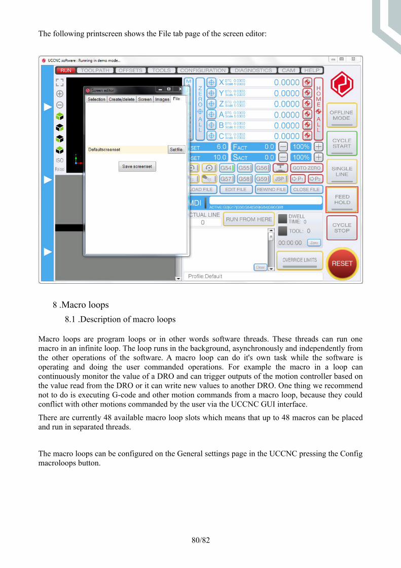
The following printscreen shows the File tab page of the screen editor:
8 .Macro loops
8.1 .Description of macro loops
Macro loops are program loops or in other words software threads. These threads can run onemacro in an infinite loop. The loop runs in the background, asynchronously and independently fromthe other operations of the software. A macro loop can do it's own task while the software isoperating and doing the user commanded operations. For example the macro in a loop cancontinuously monitor the value of a DRO and can trigger outputs of the motion controller based onthe value read from the DRO or it can write new values to another DRO. One thing we recommendnot to do is executing G-code and other motion commands from a macro loop, because they couldconflict with other motions commanded by the user via the UCCNC GUI interface.
There are currently 48 available macro loop slots which means that up to 48 macros can be placedand run in separated threads.
The macro loops can be configured on the General settings page in the UCCNC pressing the Configmacroloops button.
80/82

The following picture shows the macro loop configuration window:
8.2 .Writing macros for loops
The programming language, syntax and available functions are the same as for the standardmacros, the only difference is the running in a separated thread, in a loop.The code which surrounds the macro and written into the macroloop interface is thefollowing:
while(loop){//The macro code is executed here...Thread.Sleep(50);}
The 'loop' variable is internally defined and it's value is set based on the running state of themacro. If the loop is commanded to run then the loop variable is true, so the macro code islooped. When the loop is Stopped then the loop variable value becomes false, so the loopexecution stops as soon as the macro code finishes.There is an 50mseconds wait time programmed in the loop, so the highest frequency amacro could run is around 1/50msec = 20Hz. Of course the loop time can be longer thanthis, because the macro code itself takes some time to execute.
Because the macro runs in a loop the whole macro code is repeated from the beginning, this
81/82

arrises a problem that variables will always gets their original value on the next cycle repeat.For example:
int i= 0;i++;
The above code defines a local variable and then it increments the variable with one.The issue is that the loop repeats, so the variable will then again gets the value 0.To overcome this problem one or more internal loops can be programmed inside the macro,like I nthe following code:
int i=0;while(loop){ i++; //Do the rest of the work here... Thread.Sleep(50);//It is important to do some wait, otherwise the CPU will be overloaded!}
Please note that the loop variable was checked in the internal while loop and as previouslydescribed this variable will change value to false as soon as the macro is commanded tostop, so then the macro can safely terminate.
8.3 .Running, stopping, killing macro loops
To place a macro into a loop open up the macro loop configuration Windows and select thenumber of the macro to run and then press the Run button. The green virtual LED in thesame line will indicate if the macro starts running and the LED will be green until the loopstops running. To stop the loop press the Stop button, this will make the loop variable tobecome false and the thread can terminate.To run the loop automatically every time the UCCNC is loaded and starts up select theAutorun option.There can be cases when a macro can't be stopped, a simple macro code example for this isbelow:
while(true){ Thread.Sleep(50);}
The above code will not terminate on stop command, because the while loop is infinate andthe execution will not jump out of the loop even in the macro stop button was pressed.In this case the green Running LED will remain on indicating that the loop is still running.The Kill button can be used to abort/kill the macro execution. However this will likely notcause serious problems, but if a macro loop can't be stopped we recommend to investigateand correct the issue in the macro code.To save the settings press the save button on the bottom of the window.
82/82