ucs direct attached storage and fc zoning … 23, 2013 · ucs direct attached storage and fc zoning...
TRANSCRIPT

UCS Direct Attached Storage and FC ZoningConfiguration Example
Document ID: 116082
May 23, 2013
Contents
IntroductionPrerequisites Requirements Components Used ConventionsBackground Information UCS with DAS Earlier than Version 2.1 UCS with DAS in Version 2.1Configure Configure Direct Attached Storage Configure FC ZoningVerify Verify from GUI Verify from CLITroubleshootRelated Information
Introduction
This document provides a sample configuration of Direct Attached Storage (DAS) in the Cisco UnifiedComputer System (UCS); the configuration uses the graphical user interface (GUI) available in the UCSManager (UCSM).
With the release of UCS version 2.1, it is now possible to connect the storage array directly to the FabricInterconnect (FI) without any upstream storage area network (SAN) switch.
Contributed by Ganesh Kumar K, Cisco TAC Engineer.
Prerequisites
Requirements
Cisco recommends that you have knowledge of these topics:
UCS and UCS Manager Knowledge• Storage Area Networking• Fiber Channel Zoning Concepts•

Components Used
The information in this document is based on these software and hardware versions:
UCS setup with FI in fiber channel (FC) switch mode and with firmware version 2.1(1a) or later.• Storage array that supports UCS. Refer to UCS − Storage Interoperability Matrix for list of supportedstorage arrays.
•
The information in this document was created from the devices in a specific lab environment. All of thedevices used in this document started with a cleared (default) configuration. If your network is live, make surethat you understand the potential impact of any command.
Conventions
Refer to Cisco Technical Tips Conventions for information on document conventions.
Background Information
UCS with DAS Earlier than Version 2.1
In versions of UCS earlier than 2.1, you had the option to use DAS with UCS. However, you needed a SANswitch connected to the FI so the switch could push the zone database to the FI. That is, the UCS platform wasnot able to build a zone database. The topology was similar to this:

UCS with DAS in Version 2.1
With the release of Version 2.1, UCS now has the ability to build its own zone database. You can have DASwith UCS without the need for a SAN switch to push the zoning configuration. The topology now looks likethis:

Configure
Note: Use the Command Lookup Tool (registered customers only) in order to obtain more information on thecommands used in this section.
Configure Direct Attached Storage
The general process to configure DAS in UCS is:
Configure FI in FC switch mode.1. Create required virtual SAN (VSAN).2. Set the port role in UCS.3. Check if the storage port worldwide port name (WWPN) is logged in to the fabric.4.
This assumes the physical cables are already connected between the storage array ports and the FabricInterconnects.
Each of these steps is explained in detail in the next sections.
Configure FI in FC Switch Mode
If the FI is not already in FC switch mode, this procedure demonstrates how to change to that mode. You canstill run End Host Mode for the Ethernet.

Note: This activity requires an FI reboot.
In the UCSM, navigate to and click the Equipment tab.1. Expand Fabric Interconnects.2. Click Fabric Interconnect A.3. In the right pane, select Set FC Switching Mode.4.
Repeat Steps 1−4 for Fabric B.5.
Create Required VSAN
This procedure demonstrates how to create the required VSANs in both FIs and how to enable zoning on theVSANs. Before you start this procedure, identify which VSAN ID you want to use for both fabrics.
Note: Storage VSANS should be created only under Storage Cloud and should not be allowed in the FCuplinks if any.
In the UCSM, navigate to and click the SAN tab.1. Expand Storage Cloud.2. Expand Fabric A.3. Right−click VSANs, and select Create Storage VSAN.4. Enter a name for the VSAN.5. Select Enabled for FC Zoning.6. Select Fabric A.7. Enter the VSAN ID and a Fiber Channel over Ethernet (FCoE) VLAN ID for Fabric A. Make surethat FCoE VLAN ID is a VLAN ID that is not currently used in the network.
8.
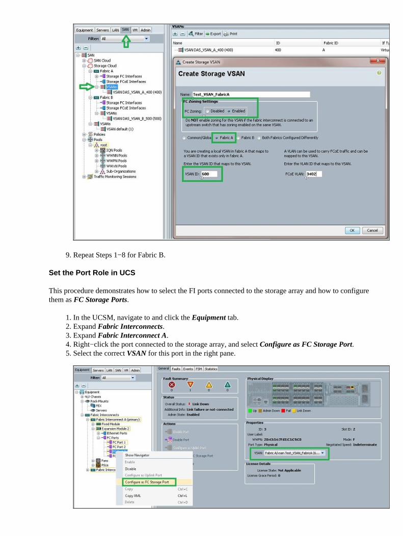
Repeat Steps 1−8 for Fabric B.9.
Set the Port Role in UCS
This procedure demonstrates how to select the FI ports connected to the storage array and how to configurethem as FC Storage Ports.
In the UCSM, navigate to and click the Equipment tab.1. Expand Fabric Interconnects.2. Expand Fabric Interconnect A.3. Right−click the port connected to the storage array, and select Configure as FC Storage Port.4. Select the correct VSAN for this port in the right pane.5.

Repeat steps 1−6 for Fabric B.6.
If the port is configured properly and is up in the storage array, the FC Storage port in UCS should comeonline.
Confirm StoragePort WWPN Is Logged in to the Fabric
This procedure ensures that the storage port WWPN is logged in to the fabric.
Log in through the secure shell (SSH), or establish a Telnet connection to the UCS Virtual IP (VIP).1. Enter the connect nxos { a | b } command, where a | b represents FI A or FI B; in this example, the FIis A.
2.
Enter the show flogi database vsan vsan ID command, where vsan ID is the identifier for the VSAN;in this example, the identifier is 600.
3.
This image is an example of output from these two commands. The storage port WWPN is now logged in toVSAN 600. Be sure to confirm the storage port login on both of the fabrics.
Configure FC Zoning
The general process to configure the server is:
Create storage connection policy.1. Create a service profile.2. Associate the service profile with the server.3.
Each of these steps is explained in detail in the next sections.
Create Storage Connection Policy
This procedure demonstrates how to create the storage connection policy and the storage target WWPN.
Note: Cisco recommends that you create one policy for each fabric so the zoning is easy to understand.

In the UCSM, navigate to and click the SAN tab.1. Expand Policies, expand Root, right−click Storage Connection Policies, and select Create StorageConnection Policy.
The Create Storage Connection Policy window opens and allows you to define the storage targetWWPN and the fabric details.
2.
Enter a Name for the storage connection policy.3. Select a Zoning Type from the three options:
None: Use this option when you do not have the zones created in the FI, but do have zonesused from the upstream FC switch for a particular VSAN.
♦
Single Initiator Single Target: Use this option when you have only one storage portconnected to one fabric. In this example, there is one target connected to each fabric.
♦
Single Initiator Multiple Targets: Use this option when you have more than one storage portconnected to one fabric.
♦
4.
Click the plus (+) sign next to the FC Target Endpoints section. The Create FC Target Endpointwindow opens.
5.
Enter the WWPN of the FC target.6. Click the Path for the fabric.7. Select the VSAN ID from the drop−down list.8.

Click OK in order to save the changes.9.
Create Service Profile
This procedure demonstrates how to create a regular service profile with additional zoning configuration.
In the UCSM, navigate to and click the Servers tab.1. Expand Servers, right−click Service Profiles, and select Create Service Profile(expert).2. Enter a name for the service profile, and select the unique identifier (UUID) pool that you alreadycreated. Click Next.
3.
In the Networking section, create the required number of virtual network interface controllers(vNICs). Click Next.
4.
In the Storage section, create the required number of virtual host bus adapters (vHBAs), and makesure that you place them in the correct VSAN for storage connectivity. This example uses VSAN 600.Click Next.
5.
In the Zoning section (which is new in UCSM 2.1), select the vHBA and the Storage ConnectionPolicy mapping in order to define the zoning. Under Select vHBA Initiators, click vHBA. Under theSelect vHBA Initiator Groups section, click the plus (+) sign in order to open a new window.
6.
Enter a Name for the Initiator Group, select the Storage Connection Policy you created previously,and click OK.
7.
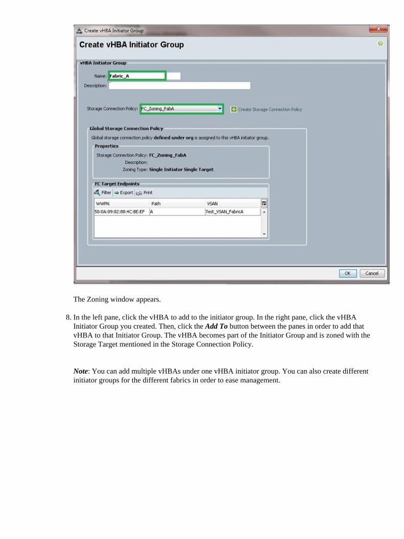
The Zoning window appears.
In the left pane, click the vHBA to add to the initiator group. In the right pane, click the vHBAInitiator Group you created. Then, click the Add To button between the panes in order to add thatvHBA to that Initiator Group. The vHBA becomes part of the Initiator Group and is zoned with theStorage Target mentioned in the Storage Connection Policy.
Note: You can add multiple vHBAs under one vHBA initiator group. You can also create differentinitiator groups for the different fabrics in order to ease management.
8.

Click Next from the Zoning section, and complete the other sections in the service profile.9.
Associate Service Profile with the Server
This procedure demonstrates how to associate the service profile with the server, which initiates the creationof zones and the zoneset.
Right−click the service profile you just created, and click Change Service Profile Association.1. Select Select Existing Server from the drop−down list.2. Select the appropriate server, and click OK. The server then reboots.3.
Verify
Use this section to confirm that your zone creation and zoneset activation work properly.
The Output Interpreter Tool (registered customers only) supports certain show commands. Use the OutputInterpreter Tool in order to view an analysis of show command output.
Verify from GUI
This procedure describes how to verify the zone configuration and zoneset activation from the GUI.
In the UCSM, navigate to and click the Servers tab.1. Expand Servers and Service Profiles.2. Navigate to and click the service profile you created previously.3. Click the FC Zones tab in the right pane.4.
In this image, the initiator and target WWPN are in the same zone. The zone Admin State is Applied, and theOper State is Active, which means the zone is part of the current active zoneset.

Note: The zone name is automatically created; you do not have any control over the name. In this example,the naming convention is ClusterName_FabricID_ZoneID_ServiceProfileName_InitiatorName.
Verify from CLI
This procedure connects to the NXOS shell of the UCS and verifies the zoning from the command−lineinterface.
Log in through the secure shell (SSH) to the UCS VIP.1. Enter the connect nxos { a | b } command, where a | b represents FI A or FI B; in this example, the FIis A.
2.
Enter the show zoneset active vsan vsan ID command, where vsan ID is the identifier for the VSAN;in this example, the identifier is 600.
3.
This image is an example of output from these two commands.
If the proper logical unit number (LUN) masking is done from the storage side, the LUN is now visible in theserver OS.
Troubleshoot
This section provides information you can use to troubleshoot your configuration.
If you have created the service profile, but cannot see the zones under the FC Zones tab, use thistroubleshooting checklist:
Is the zoning enabled on the intended VSAN?• Is the service profile associated? Zones are created only when the service profile is associated with theserver.
•
Is the correct storage connection policy selected under vHBA initiator groups?• Is the correct VHBA added to the correct vHBA initiator group?• Is the correct VSAN selected for the vHBAs?• Are the correct VSAN and fabric selected under the storage connection policy?•
Related Information
UCS 2.1 FC Zoning Configuration Guide• Technical Support & Documentation − Cisco Systems•
Updated: May 23, 2013 Document ID: 116082