ud fsae front impact analysis - university of...
TRANSCRIPT
UD FSAE Front Impact Analysis
Patrick Geneva - [email protected] Dodd - [email protected]
Last UpdatedMay 16, 2017

1 Introduction
We look to preform an analysis on the front aerodynamic devices and the front impact attenuatorto ensure that it passes all rules needed for competition. Our team uses the standard impactattenuator that was bought from “BSCI Energy Impact Systems.” In years past we have not donea aerodynamics package and thus have not needed to worry about having additional non-crushableobjects in the front of the impact attenuator. Thus for this year, as per Rule T3.21.6, we need topreform an analysis on either the mounting or the bolts. We look to preform an analysis to findthe force experience by the designed mounting bolt locations and then select the bolt that wouldensure that the peak load is not reached in a frontal impact.
2 Standard Impact Attenuator
Figure 1: Seen above is the drawing for the standard impact attenuator specified by the 2017 rules.This impact attenuator has not changed since 2013 and uses high energy absorbing foam.
See above, is the standard impact attenuator that will be used by the team. It will be securedfollowing rule T3.20.4 with eight, grade 8.8 bolts. This method, compared to gluing it with epoxy,allows for removable during transport and will prevent damage being done to the foam.
1

3 Problem Formulation
Figure 2: Above is the impact scenario that we will be preforming analysis on. The force will beapplied to the front of the vehicle to both the wing and standard impact attenuator.
The FSAE rules specify the assumptions that should be made for the crash scenario. We havea 300kg vehicle that needs to have an average deceleration of 20g’s, with a peak deceleration of40g’s. We can preform the following simple calculation to find the specified 120kN of maximumforce exerted:
F = m ∗ a= (car mass) ∗ (peak g′s) ∗ (gravity)
= (300kg) ∗ (40g′s) ∗ (9.81m/s2)
= 117kN ≈ 120kN (1)
We know from rule T3.21.6 that the standard impact has a max force of 95kN. We want preformanalysis in the worst-case scenario, and thus we assume that both the front wing and the standardimpact attenuator are being struck at the same time instant. This means that the standard impactattenuator will be taking 95kN from the total max of 120kN at this time instant. Thus the mountingbolts of the wing cannot exceed 25kN peak force. Knowing the force we can now determine thegeometry of the system. We define everything in reference to the origin of the mount and get thefollowing values:
Table 1: Geometry taken from the solidworks model of the front aerodynamic wing assembly. Alldistances are denoted in meters.
Description X Direction (m) Y Direction (m)
Mount Bolt Hole 1 0.00762 0.06858
Mount Bolt Hole 2 0.00762 0.00762
Location of Force on Wing 0.41630 -0.12192
2
4 Bolt Analysis
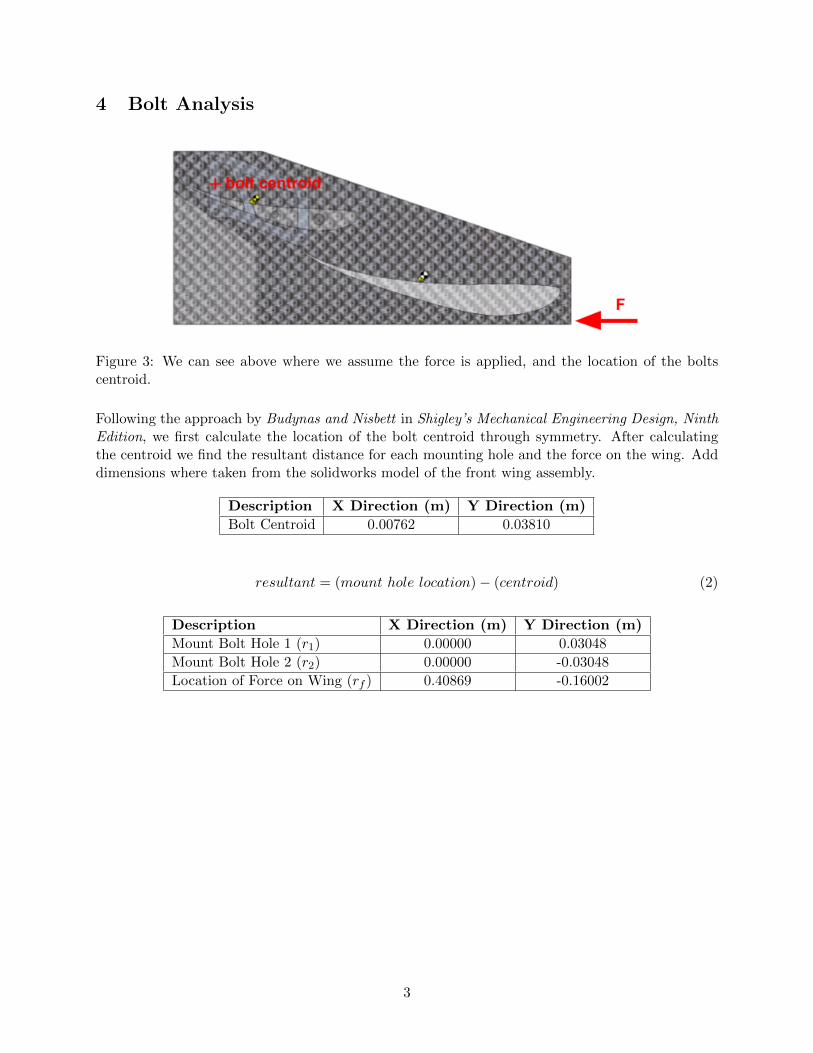
Figure 3: We can see above where we assume the force is applied, and the location of the boltscentroid.
Following the approach by Budynas and Nisbett in Shigley’s Mechanical Engineering Design, NinthEdition, we first calculate the location of the bolt centroid through symmetry. After calculatingthe centroid we find the resultant distance for each mounting hole and the force on the wing. Adddimensions where taken from the solidworks model of the front wing assembly.
Description X Direction (m) Y Direction (m)
Bolt Centroid 0.00762 0.03810
resultant = (mount hole location) − (centroid) (2)
Description X Direction (m) Y Direction (m)
Mount Bolt Hole 1 (r1) 0.00000 0.03048
Mount Bolt Hole 2 (r2) 0.00000 -0.03048
Location of Force on Wing (rf ) 0.40869 -0.16002
3

Figure 4: The distance diagram of the calculated resultants (left). Force diagram of the forcesacting on the bolt holes (right)
The total force (F) applied to the wing is the 25kN at peak load. Since there are two mountsholding the front wing up on either side of the car we half this total force to get an applied forceof 12.5kN on a single mount. We can now calculate the primary shear caused by this force on asingle mount
F ′ = − F
num bolts= −12.5kN
2 bolts= −6.25kN (3)
We can now calculate the secondary shear caused by the moment of the force being offset vertically.The moment at the bolt centroid is the following:
M = F ∗ rf = (12.5kN) ∗ (−0.16002) = −2kNm (4)
Now we can calculate the secondary shear caused by this moment. Give by the weighted distancefraction of shear that each bolts gets, is given as the following for each bolt in the mount:
F ′′1 = − M ∗ r1
(r1)2 + (r2)2= −32.8kN (5)
F ′′2 = − M ∗ r2
(r1)2 + (r2)2= 32.8kN (6)
Taking the combined magnitude of these resulting forces, we have the following for the total forceon bolt 1 and bolt 2.
F1 = −39.0kN F2 = 26.6kN (7)
Now that we have the magnitude of shear force experience by the bolt, we can compute the averageshear stress felt in each bolt. To do so we need the cross sectional area that the force is beingapplied through. We will be using fully threaded fine thread bolts, and thus can attain the crosssectional areas of the smallest diameter in the bolt. See Appendix A for the full table that wasreferenced.
τ =F
Ashear(8)
4
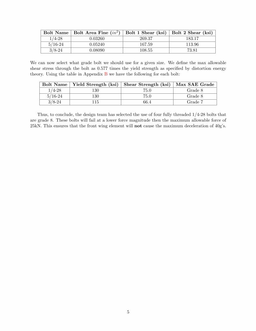
Bolt Name Bolt Area Fine (in2) Bolt 1 Shear (ksi) Bolt 2 Shear (ksi)
1/4-28 0.03260 269.37 183.17
5/16-24 0.05240 167.59 113.96
3/8-24 0.08090 108.55 73.81
We can now select what grade bolt we should use for a given size. We define the max allowableshear stress through the bolt as 0.577 times the yield strength as specified by distortion energytheory. Using the table in Appendix B we have the following for each bolt:
Bolt Name Yield Strength (ksi) Shear Strength (ksi) Max SAE Grade
1/4-28 130 75.0 Grade 8
5/16-24 130 75.0 Grade 8
3/8-24 115 66.4 Grade 7
Thus, to conclude, the design team has selected the use of four fully threaded 1/4-28 bolts thatare grade 8. These bolts will fail at a lower force magnitude then the maximum allowable force of25kN. This ensures that the front wing element will not cause the maximum deceleration of 40g’s.
5
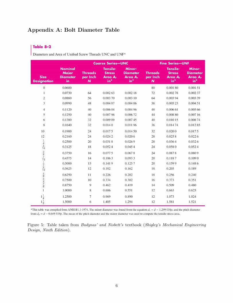
Appendix A: Bolt Diameter Table
Figure 5: Table taken from Budynas’ and Nisbett’s textbook (Shigley’s Mechanical EngineeringDesign, Ninth Edition).
6

Appendix B: Bolt Grade Table
Figure 6: Table taken from Budynas’ and Nisbett’s textbook (Shigley’s Mechanical EngineeringDesign, Ninth Edition).
7

Appendix C: FSAE Rules
T3.20.2 The Impact Attenuator must be
• At least 200 mm (7.8 in) long, with its length oriented along the fore/aft axis of the Frame.
• At least 100 mm (3.9 in) high and 200 mm (7.8 in) wide for a minimum distance of 200 mm(7.8 in) forward of the Front Bulkhead.
• Attached securely to the Anti-Intrusion Plate or directly to the Front Bulkhead.
T3.20.3 The Anti-Intrusion Plate must
• Be a 1.5 mm (0.060 in) solid steel or 4.0 mm (0.157 in) solid aluminum plate, or an approvedalternative as per T3.38.
• Attach securely and directly to the Front Bulkhead.
• Have an outer profile must extend at least to the centerline of the Front Bulkhead tubes onall sides (note that this is for welded attachment of the impact plate).
T3.20.4 Attaching the Impact Attenuator
• Welding, where the welds are either continuous or interrupted. If interrupted, the weld/spaceratio must be at least 1:1. All weld lengths must be greater than 25 mm (1 in).
• Bolted joints, using a minimum of eight (8) 8 mm Metric Grade 8.8 (5/16” SAE Grade 5)bolts with positive locking. The distance between any two bolt centers must be at least 50mm (2 in).
T3.21.2 Impact Attenuator Data Requirement
• Teams using the standard Impact Attenuator are not required to submit test data with theirIAD Report, but all other requirements must be included. In addition, photos of the actualattenuator and evidence that it meets the design criteria in Appendix T-3 must be appendedto the report.
T3.21.6 Impact Attenuator Data RequirementTeams with any non-crushable object(s) that do not meet the requirements of T3.22.2(c) mustprove the combination of their Impact Attenuator Assembly and non-crushable object(s) do notexceed the peak deceleration of 40g (rule T3.21.2). Any of the following methods may be used toprove the design does not exceed 120kN:
(a) Physical testing of the Impact Attenuator Assembly including any required non-crushableobject(s). See fsaeonline.com FAQs for an example of the structure to be included in the testfor wings and wing mounts
(b) Combining the peak force from physical testing of the Impact Attenuator Assembly with thefailure load for the mounting of the non-crushable object(s), calculated from fastener shearand/or link buckling.
(c) Combining the “standard” Impact Attenuator peak load of 95kN with the failure load for themounting of the non-crushable object(s), calculated from fastener shear and/or link buckling.
8