ud series dc servo drives user guide - parker hannifin · 2001-07-09 · ud series dc servo drives...
TRANSCRIPT

UD Series DC Servo Drives
User Guide
For engineering For engineeringassistance in Europe: assistance in the U.S.:Parker Hannifin plc Parker Hannifin CorporationElectromechanical Division - Digiplan Compumotor Division21 Balena Close 5500 Business Park Drive, Suite DPoole, Dorset Rohnert Park, CA 94928England, BH17 7DX USATelephone: 01202-699000 Telephone: (800) 358-9070Fax: 01202-695750 Fax: (707) 584-8015e-mail: [email protected] e-mail: [email protected]
Part No: 1600.037.07 December, 1996


IMPORTANT INFORMATION FOR USERS
Installation and Operation of Digiplan Equipment
It is important that Digiplan motion control equipment is installed and operated in such a way that all applicable safetyrequirements are met. Note that it may be necessary for the complete installation to comply with the Low VoltageDirective or Machinery Directive. It is your responsibility as an installer to ensure that you identify the relevant safetystandards and comply with them; failure to do so may result in damage to equipment and personal injury. In particular,you should study the contents of this user guide carefully before installing or operating the equipment.
Under no circumstances will the suppliers of the equipment be liable for any incidental, consequential or specialdamages of any kind whatsoever, including but not limited to lost profits arising from or in any way connected with theuse of the equipment or this user guide.
! SAFETY WARNINGHigh-performance motion control equipment is capable of producing rapid movement and very high forces.Unexpected motion may occur especially during the development of controller programs. KEEP WELL CLEAR ofany machinery driven by stepper or servo motors. Never touch any part of the equipment while it is in operation.
This product is sold as a motion control component to be installed in a complete system using good engineeringpractice. Care must be taken to ensure that the product is installed and used in a safe manner according to localsafety laws and regulations.
High voltages exist within enclosed units, on rack system backplanes (motherboards) and on transformer terminals.Keep clear of these areas when power is applied to the equipment.
If the equipment is used in any manner that does not conform to the instructions given in this manual , then theprotection provided by the equipment may be impaired.
The information in this user guide, including any apparatus, methods, techniques, and concepts described herein,are the proprietary property of Parker Digiplan or its licensors, and may not be copied, disclosed, or used for anypurpose not expressly authorised by the owner thereof.
Since Digiplan constantly strives to improve all of its products, we reserve the right to modify equipment and userguides without prior notice. No part of this user guide may be reproduced in any form without the prior consent ofDigiplan.
© Digiplan Division of Parker Hannifin plc, 1996– All Rights Reserved –


User Guide Change Summary
The following is a summary of the primary changes to this userguide since the last version was released. This user guide, version1600.037.07, supersedes version 1600.037.06.
When a user guide is updated, the new or changed text isdifferentiated with a change bar in the outside margin (thisparagraph is an example). If an entire chapter is changed, thechange bar is located on the outside margin of the chapter title.
Removal of the DC Series Servo Motor Data Appendix.
Alteration of the supply voltage for the UD Series of DC ServoDrives.
EMC and LVDCompliance
Considerations
The UD Series of drives are sold as complex components toprofessional assemblers, as components they are not compliantwith Electromagnetic Compatibility Directive 89/336/EEC.
The UD Series of drives are for use only at voltages under 75VDC, and are therefore outside the scope of current LVDrequirements.
Note: Care must be taken particularly in transformer selection andwiring to ensure safety of the installation. The complete systemmay need to conform with either the Low Voltage Directive or theMachinery Directive.

CONTENTS i
Contents
CHAPTER 1. GENERAL DESCRIPTION ............................................................... 1Introduction ...................................................................................................................................... 1Summary of Features..................................................................................................................... 2
Protection Circuits............................................................................................................... 2Function Indicators ............................................................................................................. 2Adjustments ......................................................................................................................... 2Outputs and Inputs.............................................................................................................. 2Other Features..................................................................................................................... 2Options.................................................................................................................................. 2
Specification.................................................................................................................................... 3Variant Information ......................................................................................................................... 4
CHAPTER 2. INSTALLATION ............................................................................... 5Installation........................................................................................................................................ 5Connector Identification................................................................................................................. 5
Single-voltage Supply Connection................................................................................. 5Dual-voltage Supply Connection .................................................................................... 5Dual-voltage Sub-rack - Supply Protection Requirement......................................... 6Motor AC Supply Connection........................................................................................... 6Primary Fuse Ratings......................................................................................................... 7Disconnect Device.............................................................................................................. 7
Environmental Considerations..................................................................................................... 7Logic Supply..................................................................................................................................14Fuse Ratings..................................................................................................................................14Motor Connections .......................................................................................................................15Signal Connections......................................................................................................................15Control Signals .............................................................................................................................15
Signal Input PLB Pins 3 and 4 .......................................................................................15Tachometer Input PLA Pins 7 and 8..............................................................................15Limit Switch Inputs PLB Pins 9 and 10.........................................................................16External Disable PLB Pin 8.............................................................................................16+/-15v Auxiliary Outputs PL9 Pins 4 and 6 (Pin 5 is 0v.) ...........................................1624v DC Unregulated ........................................................................................................16Velocity Amp Input PLB Pin 2.........................................................................................16Reset Input PL4 Pin 8 (Power Supply Card) ...............................................................17
Limit Polarity Link..........................................................................................................................17Protection Circuits.........................................................................................................................17
General...............................................................................................................................17Power Supply Card LED 1 (Lowest Position) .............................................................18Power Supply LED 2........................................................................................................18Power Supply LED 3........................................................................................................18Power Supply LED 4 (Top Position) .............................................................................18Axis Card LED 1 (Top Position) .....................................................................................18Axis Card LED 2................................................................................................................18
CHAPTER 3. SETTING UP THE DRIVE .............................................................. 1 9Initial Precautions .........................................................................................................................19Setting-up Procedure...................................................................................................................19
CHAPTER 4. OPERATION .................................................................................. 2 3
ii UD SERIES DC SERVO DRIVES
Theory of Operation - Axis Card ................................................................................................ 23Output Stage ..................................................................................................................... 24Input Section and Velocity Error Amplifier................................................................... 24Current Error Amplifier..................................................................................................... 25Pulse Width Modulator .................................................................................................... 25Gating ................................................................................................................................. 25Current Sense................................................................................................................... 25Overcurrent Detector........................................................................................................ 26
Theory of Operation - Power Supply Card .............................................................................. 26Logic Supply ..................................................................................................................... 27Active Pull-off Supply Generation ................................................................................. 27Fault Monitoring................................................................................................................ 27Enable/Reset Circuitry..................................................................................................... 28Power Dump Circuit......................................................................................................... 28
CHAPTER 5. TROUBLESHOOTING .................................................................... 2 9General........................................................................................................................................... 29Module Removal and Replacement.......................................................................................... 29Power Supply Card...................................................................................................................... 29
LED 1 (Red): Lowest Position ........................................................................................ 29LED 2 (Red)....................................................................................................................... 29LED 3 (Green)................................................................................................................... 30LED 4 (Green)................................................................................................................... 30
Axis Card........................................................................................................................................ 30Overcurrent LED Illumination......................................................................................... 30Overtemperature LED Illumination................................................................................ 31Incorrect Operation........................................................................................................... 31
Returning the System .................................................................................................................. 32INDEX......................................................................................................................................................... 32
CONTENTS iii
List of Figures
Figure 1. Customer Connections for UR3 DC Drive Rack (3-axis)................................................... 8Figure 2. Customer Connections for UR8 DC Drive Rack.................................................................. 9Figure 3. Customer Connections for UR8 DC Drive Rack................................................................10Figure 4. Customer Connections for UR8 DC Drive Rack................................................................12Figure 5. Relationship Between I LIMIT Control and Current..........................................................21Figure 6. Tacho Signal Waveforms......................................................................................................22Figure 7. Axis Card Schematic..............................................................................................................23Figure 8. Power Supply Card Schematic............................................................................................26

iv UD SERIES DC SERVO DRIVES

CHAPTER 1. GENERAL DESCRIPTION 1
CHAPTER 1. GENERAL DESCRIPTION
Introduction The UD2/5 is a high performance, low-loss pulse width modulatedDC servo drive suitable for use with permanent-magnet servomotors.
The system comprises a 3U power sub-rack to which may be fittedup to three or eight axis cards, depending on the type. The UD5 iscapable of delivering a continuous output power of over 1/2hp(375W) and the UD2 1/5hp (150W). Adjustable current limitingallows the drive to be matched to a wide range of motors. Inaddition, again depending on the type, the sub-rack may supportone of the following options:
(a) A single DC motor supply rail, so that all motors are poweredfrom the same DC supply.
(b) Two DC motor supply rails, so that motors may be run fromdifferent DC supply rails, thus allowing more accurate matching of amotor to its application (UR8 model only).
The drive is fully protected against damage caused by overheatingand by short-circuits across motor connections or to earth.Additional protection circuitry monitors the voltage rails within thedrive and disables the power switches if these fall outside thespecification.
Inputs are provided for directional limit switches and each axis maybe disabled independently.
The power supply card has a built-in power dump circuit whichpermits full four-quadrant operation.
2 UD SERIES DC SERVO DRIVES
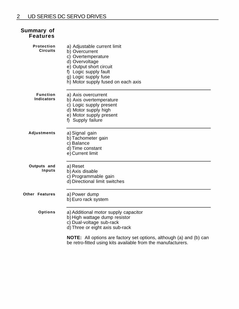
Summary ofFeatures
ProtectionCircuits
a) Adjustable current limitb) Overcurrentc) Overtemperatured) Overvoltagee) Output short circuitf) Logic supply faultg) Logic supply fuseh) Motor supply fused on each axis
FunctionIndicators
a) Axis overcurrentb) Axis overtemperaturec) Logic supply presentd) Motor supply highe) Motor supply presentf) Supply failure
Adjustments a) Signal gainb) Tachometer gainc) Balanced) Time constante) Current limit
Outputs andInputs
a) Resetb) Axis disablec) Programmable gaind) Directional limit switches
Other Features a) Power dumpb) Euro rack system
Options a) Additional motor supply capacitorb) High wattage dump resistorc) Dual-voltage sub-rackd) Three or eight axis sub-rack
NOTE: All options are factory set options, although (a) and (b) canbe retro-fitted using kits available from the manufacturers.
CHAPTER 1. GENERAL DESCRIPTION 3
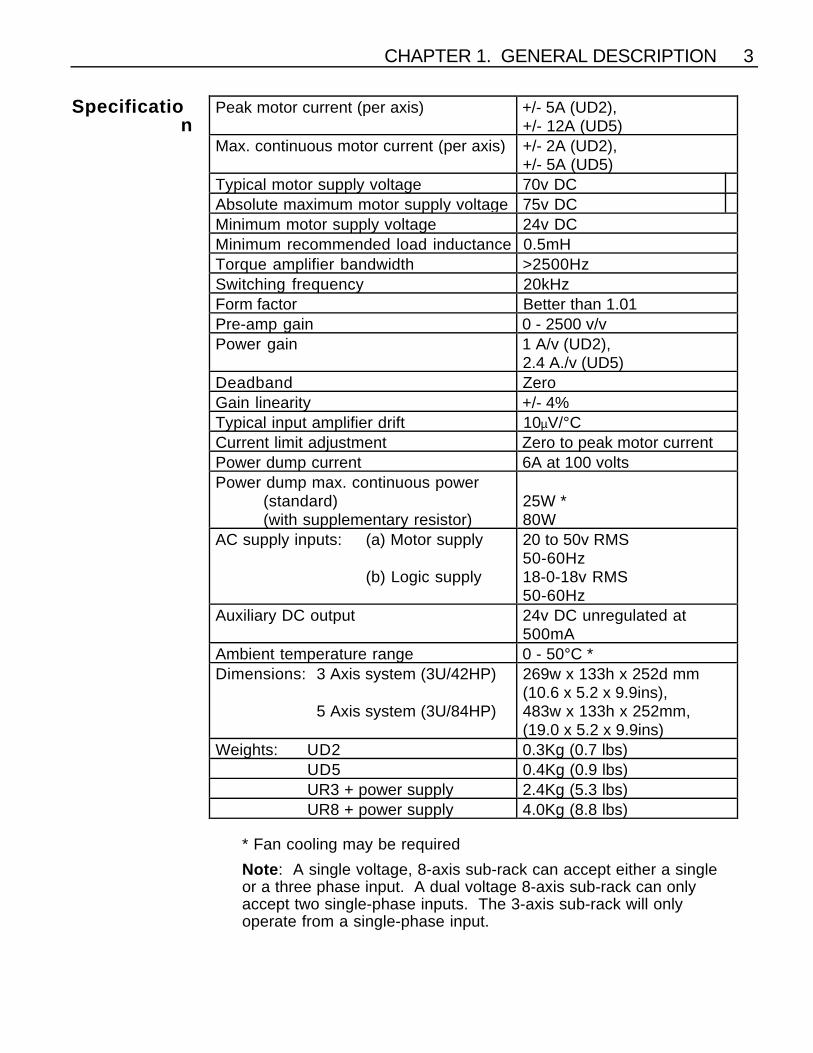
Specification
Peak motor current (per axis) +/- 5A (UD2),+/- 12A (UD5)
Max. continuous motor current (per axis) +/- 2A (UD2),+/- 5A (UD5)
Typical motor supply voltage 70v DCAbsolute maximum motor supply voltage 75v DCMinimum motor supply voltage 24v DCMinimum recommended load inductance 0.5mHTorque amplifier bandwidth >2500HzSwitching frequency 20kHzForm factor Better than 1.01Pre-amp gain 0 - 2500 v/vPower gain 1 A/v (UD2),
2.4 A./v (UD5)Deadband ZeroGain linearity +/- 4%Typical input amplifier drift 10µV/°CCurrent limit adjustment Zero to peak motor currentPower dump current 6A at 100 voltsPower dump max. continuous power
(standard)(with supplementary resistor)
25W *80W
AC supply inputs: (a) Motor supply
(b) Logic supply
20 to 50v RMS50-60Hz18-0-18v RMS50-60Hz
Auxiliary DC output 24v DC unregulated at500mA
Ambient temperature range 0 - 50°C *Dimensions: 3 Axis system (3U/42HP)
5 Axis system (3U/84HP)
269w x 133h x 252d mm(10.6 x 5.2 x 9.9ins),483w x 133h x 252mm,(19.0 x 5.2 x 9.9ins)
Weights: UD2 0.3Kg (0.7 lbs)UD5 0.4Kg (0.9 lbs)UR3 + power supply 2.4Kg (5.3 lbs)UR8 + power supply 4.0Kg (8.8 lbs)
* Fan cooling may be required
Note : A single voltage, 8-axis sub-rack can accept either a singleor a three phase input. A dual voltage 8-axis sub-rack can onlyaccept two single-phase inputs. The 3-axis sub-rack will onlyoperate from a single-phase input.
4 UD SERIES DC SERVO DRIVES
VariantInformation
There are two alternative sub-racks available for UD series drives.
The UR3 sub-rack can accommodate up to three drives togetherwith a power supply card. All drives operate from the same motorsupply voltage.
The UR8 sub-rack accommodates up to eight drives and a powersupply card. This sub-rack can be supplied in either single or dualmotor supply versions. A dual supply sub-rack can be identified bya break in the main HV1 rail and a track cut next to the HV1 pillar.The position of the breaks depends on the number of drivesconnected to the HV1 and HV2 supplies, and this is indicated by anumber to be found adjacent to the HV1 rail break. 2/6 wouldindicate 2 drives at HV1 and 6 drives at HV2. Any combination ofhigh and low voltage drives can be configured, the HV1 drivesbeing located next to each other and closest to the power supplycard.
Both the UR3 and UR8 sub-racks can be populated with anycombination of UD2 and UD5 drives. The UD5 can be identified bythe addition of a heatsink fitted with two metal-cased resistors.
IMPORTANT. A dual-voltage rack is intended to be operated withHV1 as the higher of the two supplies and HV2 as the lower. Whenconnecting a dual-voltage system, always ensure that HV1 isgreater than or equal to HV2 AT ALL TIMES, even in the event of asupply protection device operating. See 'Dual-voltage sub-rack -supply protection requirement' for further details.
CHAPTER 2. INSTALLATION 5
CHAPTER 2. INSTALLATION
Installation UD Series drives must be installed by competent personnel familiarwith the installation, commissioning and operation of motion controlequipment.
The drive system should be installed in an area where there isadequate ventilation above and below the sub-racks. The UR8sub-rack can be mounted in a standard 19" cabinet. In someapplications involving high duty cycles, ventilation fans and/oradditional dump resistors may be required. Ensure the drive 0Vand transformer screen are earthed. In the final application theequipment must be enclosed to prevent the operator coming intocontact with any high voltages. This includes the transformer, driveand motor terminations.
Metal equipment cabinets offer the most advantages for siting theequipment since they can provide operator protection, EMCscreening and can be readily fitted with interlocks arranged toremove all AC power when the cabinet door is opened. This formof installation also allows the fitting of metal trays beneath theequipment to act as a flame barrier, which should be provided inthe final installation.
ConnectorIdentification
The motherboard is fitted with two connectors behind each axiscard for signal and motor connections. These are identified by anumber such as PL2A or PL5B. The number refers to the axisposition, and A or B indicates a motor or signal connector.References in this manual are general and do not relate to specificaxis positions, so a typical reference would be "PLA pin 2".
Single-voltageSupply
Connection
Figs. 1 & 2 show a typical connection scheme for a basic single-axis system using a single voltage sub-rack. Obviously additionalcontrol connections may be required.
Dual-voltageSupply
Connection
Fig. 3 shows a similar scheme, but using a dual voltage sub-rack.As with the single voltage rack, additional control connections maybe required.

6 UD SERIES DC SERVO DRIVES
Dual-voltageSub-rack -
SupplyProtection
Requirement
Note that when using a dual voltage sub-rack, the supply to theHV1 connections must ALWAYS be equal to or greater than thesupply to the HV2 connections. Failure to comply with thisrequirement will result in damage to the unit. This applies at alltimes, even under fault conditions, therefore fuses should bearranged to ensure that the HV2 supply is removed in the event ofoperation of HV1 supply protection.
Motor AC SupplyConnection
The motor supply will be derived from an isolating transformer andthe voltage will depend on the application. The isolatingtransformer may be single phase or, in the case of a UR8 single-voltage chassis, either single phase or three phase. In either casethe transformer should be rated for the total loading. This clearlydepends on the duty cycle but would be typically 25-50VA per axisfor the UD2 and 60-150VA per axis for the UD5. A fuse should befitted in the primary circuit suitably rated for the AC supply and thetransformer loading.
If an alternative transformer is used it must have an earthed screenbetween the primary and secondary windings and the insulationrating between primary and secondary should be adequate toensure safety (minimum of 2300V AC rms).
For mains wiring, use approved mains cable of at least 0.75mm2
CSA, taking care to keep all mains wiring away from all secondaryand signal wiring. Ensure that the transformer terminations aresuitably enclosed to prevent operator contact. either by fitting asuitable cover or enclosing the transformer within a housing. Note:low power secondaries must be separately fused with an in-linefuse in the wire close to the transformer. The fuse value should beapproximately twice the current rating of the secondary windingbeing used (with a time delay characteristic).
Connections between the transformer secondary and the rackshould not be made until the appropriate point in the setting-upprocedure is reached.
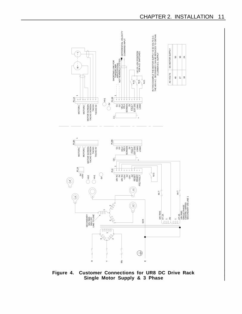
The transformer secondary is connected to M5 screw terminals onthe back of the sub-rack. In the case of a single-voltage 8-axis rack,both pairs of terminals are used in parallel for single-phaseworking, i.e. one side to L1/L3 and the other to L2/L4. Threeterminals are used for three-phase working as shown in Fig. 4. Inthe case of the dual-voltage rack the connections are made to L1and L2 (HV1), and to L3 and L4 (HV2) as indicated in Fig. 3.

CHAPTER 2. INSTALLATION 7
Primary FuseRatings
Primary fuses need to be rated to protect the transformer andsecondary wiring from short circuit faults whilst withstanding theprimary in-rush current at power up.The value of fuse required is given by:
1.5 × VAsupply volts
in amps
Fuses need to be of the anti-surge high breaking capacity type,which have a limited range of values, consequently you may needto select the next highest standard value rather than the calculatedvalue. For example, a 700VA transformer used with a supply of240V will require a 4.4A fuse, consequently the next higheststandard value of 5A will need to be selected. Note: If the live wirecannot be readily identified, fuse both phase conductors.
DisconnectDevice
A disconnect device must be provided which isolates all mainssupply current-carrying conductors. If the mains supply ispermanently connected, a switch or circuit breaker must beincluded in the wiring. It must be placed close to the equipment(less than 1 metre) and marked as the disconnecting device for theequipment.
EnvironmentalConsiderations
The drive system should be operated in the temperatures range 0 to50C° (32 to 122°F) and at a relative humidity between 0 and 95%(non-condensing). Make sure the system is stored in temperaturesfrom -40°C to 85°C (-40°F to 185°F).
The UD Series of drives can be used in a Pollution Degree 2environment i.e., one in which only non-conductive pollution occurs.

8 UD SERIES DC SERVO DRIVES
243655
182740
AC
VO
LTS
DC
MO
TO
R S
UP
PLY
E L N
TO
138A
1P
L9
L1
AN
OT
HE
R T
AP
PIN
G A
LO
WE
R V
OLT
AG
E M
AY
BE
OB
TA
INE
D.
CH
OS
EN
TO
BE
66
VO
LTS
DC
. BY
CH
OO
SIN
GIN
TH
IS E
XA
MP
LE T
HE
HV
MO
TO
R S
UP
PLY
IS
FO
R N
.O. S
WIT
CH
ES
LK1
IN +
15V
PO
SIT
ION
CO
MM
AN
D IN
PU
TD
IFF
ER
EN
TIA
L V
ELO
CIT
YN
OT
NO
RM
ALL
Y F
ITT
ED
AP
PLI
CA
TIO
NS
TO
RQ
UE
AM
PS
HO
RT
ING
LIN
K F
OR
N.O
.
N.O
.
N.O
.
TM
TA
CH
OT
AC
HO
TA
CH
O
18V
RM
S O
/C @
1A
0V18V
RM
S O
/C @
1A
AS
SY
.No.
1343
.017
D
B
C
A
50
120
110
100
5
0
240V
A.C
.O
R11
0V
@ 7
,5A
O/C
VO
LTS
RM
S
N.O
.
++
+
11
1
11
1
C1
C2
C3
PL3
BP
L2B
PL1
B
PL1
AP
L2A
0V0V
0V
HV
HV
HV
0V
HV
L2
100
110
120
018274048+
R1
PL3
A
D4
D5
SE
RIA
L N
o.
PL1
4
+24
V0V
PC
B 1
343.
016.
02
PS
U F
AU
LTR
EA
DY
RE
SE
T0V
-15V0V
+15
V18
V A
C0V18
V A
C
TA
CH
O 0
V
TA
CH
O S
CR
EE
NM
OT
OR
SC
RE
EN
MO
TO
R2
MO
TO
R1
MO
TO
R1
MO
TO
R2
MO
TO
R S
CR
EE
NT
AC
HO
SC
RE
EN
TA
CH
O 0
VT
AC
HO
0V
TA
CH
O S
CR
EE
NM
OT
OR
SC
RE
EN
MO
TO
R2
MO
TO
R1
G1
G2
VE
L2V
EL1
SC
RE
EN
0V
LSW
1LS
W2
G1
G2
VE
L2V
EL1
SC
RE
EN
0V
LSW
1LS
W2
LSW
2LS
W1
0VS
CR
EE
NV
EL1
VE
L2G2
G1
EX
T.D
ISF
AU
LTF
AU
LTE
XT
.DIS
FA
ULT
EX
T.D
IS
2A T
2A T
6648
Figure 1. Customer Connections for UR3 DC Drive Rack (3-axis)

CHAPTER 2. INSTALLATION 9
NLE
DC
MO
TO
R S
UP
PLY
AC
VO
LTS
40 27
55 36
0
1P
L9
18V
RM
S O
/C @
2A
18V
RM
S O
/C @
2A
20
018
SC
R
TO
139A
HV
1
L3
L4
L1
20 20
0
120
110
0
110
120
LSW
2LS
W1
EX
T.D
ISF
AU
LT0VS
CR
EE
NV
EL1
VE
L2G2
G1
MO
TO
R1
MO
TO
R2
MO
TO
R S
CR
EE
NT
AC
HO
SC
RE
EN
TA
CH
O 0
V
18V
AC
0V18
V A
C+
15V 0V
-15V 0V
RE
SE
TR
EA
DY
PS
U F
AU
LT
0V+
24V
PL1
4
PL8
A
48 40 27 18 0
120
110
HV
2
0V
PL8
BC
8
1 1
+
N.O
.
RM
SO
/C V
OLT
S11
0VO
R24
0V A
.C. 0
110
120
20
0V
TA
CH
O
L2
G1
G2
VE
L2V
EL1
SC
RE
EN
0V
LSW
1LS
W2
MO
TO
R1
MO
TO
R2
MO
TO
R S
CR
EE
NT
AC
HO
SC
RE
EN
TA
CH
O 0
V
HV
1
0V
PL1
A
PL1
BC
1
1 1
+
TA
CH
O
MT
N.O
.
N.O
.
N.O
.SH
OR
TIN
G L
INK
FO
RT
OR
QU
E A
MP
AP
PLI
CA
TIO
NS
NO
T N
OR
MA
LLY
FIT
TE
DD
IFF
ER
EN
TIA
L V
ELO
CIT
YC
OM
MA
ND
INP
UT
LK1
IN +
15V
PO
SIT
ION
FO
R N
.O. S
WIT
CH
ES
IN T
HIS
AP
PLI
CA
TIO
N A
LL A
XE
S A
RE
FE
D F
RO
MA
66
VO
LT D
C S
UP
PLY
. BY
CH
OO
SIN
G A
NO
TH
ER
TA
PP
ING
A L
OW
ER
VO
LTA
GE
MA
Y B
E O
BT
AIN
ED
FA
ULT
EX
T.D
IS
4A T
4A T
4866
Figure 2. Customer Connections for UR8 DC Drive RackSingle Motor Supply & Single Phase

10 UD SERIES DC SERVO DRIVES
MA
X O
/C @
11A
2418
3655
2740
AC
VO
LTS
DC
MO
TO
R S
UP
PLY
E L N(H
V1)
RM
S
20
48 40 27
CO
ULD
BE
OB
TA
INE
D F
OR
HV
1B
Y C
HO
OS
ING
AN
OT
HE
R T
AP
PIN
G A
LO
WE
R V
OLT
AG
EIN
TH
IS E
XA
MP
LE H
V1
IS 6
6V D
C &
HV
2 IS
24V
DC
FO
R N
.O. S
WIT
CH
ES
LK1
IN +
15V
PO
SIT
ION
CO
MM
AN
D IN
PU
TD
IFF
ER
EN
TIA
L V
ELO
CIT
YN
OT
NO
RM
ALL
Y F
ITT
ED
AP
PLI
CA
TIO
NS
TO
RQ
UE
AM
PS
HO
RT
ING
LIN
K F
OR
N.O
.
N.O
.
N.O
.
TM
TA
CH
O
+
11
C1
PL1
B
PL1
A
0V
HV
1
TA
CH
O 0
V
TA
CH
O S
CR
EE
NM
OT
OR
SC
RE
EN
MO
TO
R2
MO
TO
R1
LSW
2LS
W1
EX
T.D
ISF
AU
LT0VS
CR
EE
NV
EL1
VE
L2G2
G1
L2
TA
CH
O
0V
0
120
1100
240V
A.C
.
(HV
2)M
AX
O/C
RM
S
N.O
.
+
11
C8
PL8
B
0V
HV
2
110
120
018
PL8
A
PL1
4
+24
V0V
PS
U F
AU
LTR
EA
DY
RE
SE
T0V
-15V0V
+15
V18
V A
C0V
18V
AC
TA
CH
O 0
V
TA
CH
O S
CR
EE
NM
OT
OR
SC
RE
EN
MO
TO
R2
MO
TO
R1 G
1G
2V
EL2
VE
L1S
CR
EE
N0V
FA
ULT
EX
T.D
ISLS
W1
LSW
2
120
110
0
110
120 02020
L1
L4
L3
HV
1
TO
139A
SC
R
18 0
20
18V
RM
S O
/C @
2A
18V
RM
S O
/C @
2A
PL9
1
4A T
4A T
6648
Figure 3. Customer Connections for UR8 DC Drive RackDual Motor Supply & Single Phase
CHAPTER 2. INSTALLATION 11
1824
E
BluYR
3655
2740
AC
VO
LTS
DC
MO
TO
R S
UP
PLY
11AT
2A
SE
CO
ND
AR
Y O
N L
INE
1C
EN
TR
E T
AP
PE
DS
ING
LE P
HA
SE
18V
RM
S
23
1
32
1
A L
OW
ER
D.C
. SU
PP
LYT
HE
40V
A.C
. SE
CO
ND
AR
Y C
AN
BE
RE
DU
CE
D T
O O
BT
AIN
IN T
HIS
EX
AM
PLE
TH
E M
OT
OR
SU
PP
LY IS
55
VO
LTS
D.C
.
FO
R N
.O. S
WIT
CH
ES
LK1
IN +
15V
PO
SIT
ION
CO
MM
AN
D IN
PU
TD
IFF
ER
EN
TIA
L V
ELO
CIT
YN
OT
NO
RM
ALL
Y F
ITT
ED
AP
PLI
CA
TIO
NS
TO
RQ
UE
AM
PS
HO
RT
ING
LIN
K F
OR
N.O
.
N.O
.
N.O
.
TM
TA
CH
O
+
11
C1
PL1
B
PL1
A
0V
HV
1
TA
CH
O 0
V
TA
CH
O S
CR
EE
NM
OT
OR
SC
RE
EN
MO
TO
R2
MO
TO
R1
LSW
2LS
W1
EX
T.D
ISF
AU
LT0VS
CR
EE
NV
EL1
VE
L2G2
G1
L2
TA
CH
O
0V
LIN
E T
O L
INE
MA
X O
/C50
V R
MS
N.O
.
+
1
C8
PL8
B
0VHV
2
PL8
A
PL1
4
+24
V0V
PS
U F
AU
LTR
EA
DY
RE
SE
T0V
-15V0V
+15
V18
V A
C0V
18V
AC
TA
CH
O 0
V
TA
CH
O S
CR
EE
NM
OT
OR
SC
RE
EN
MO
TO
R2
MO
TO
R1 G
1G
2V
EL2
VE
L1S
CR
EE
N0V
FA
ULT
EX
T.D
ISLS
W1
LSW
2
L1
L4
L3
HV
1
SC
R AT
2A
18V
RM
S
PL9
1
SE
CO
ND
AR
Y
4A T
4A T
Figure 4. Customer Connections for UR8 DC Drive RackSingle Motor Supply & 3 Phase
12 UD SERIES DC SERVO DRIVES
When connecting up a dual-voltage chassis note that the utmostcare must be taken to ensure that the HV1 supply is never lowerthan the HV2 supply. See 'Dual-voltage sub-rack - protectionrequirement'.
NOTE: When using one transformer to power more than one sub-rack, a separate secondary winding is required for each rack.Similarly when using one transformer to power both the HV1 andHV2 supplies of a dual-voltage system, a separate secondarywinding should be used for each supply.
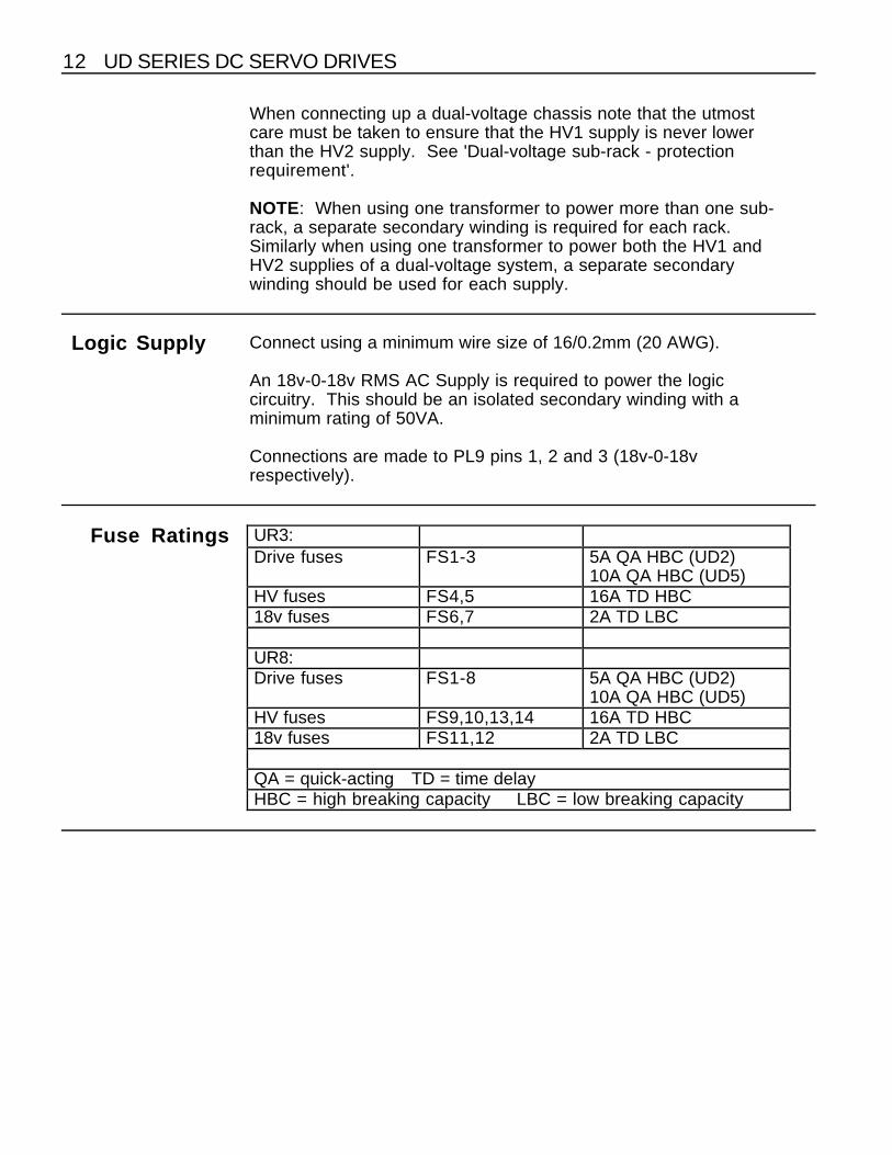
Logic Supply Connect using a minimum wire size of 16/0.2mm (20 AWG).
An 18v-0-18v RMS AC Supply is required to power the logiccircuitry. This should be an isolated secondary winding with aminimum rating of 50VA.
Connections are made to PL9 pins 1, 2 and 3 (18v-0-18vrespectively).
Fuse Ratings UR3:Drive fuses FS1-3 5A QA HBC (UD2)
10A QA HBC (UD5)HV fuses FS4,5 16A TD HBC18v fuses FS6,7 2A TD LBC
UR8:Drive fuses FS1-8 5A QA HBC (UD2)
10A QA HBC (UD5)HV fuses FS9,10,13,14 16A TD HBC18v fuses FS11,12 2A TD LBC
QA = quick-acting TD = time delayHBC = high breaking capacity LBC = low breaking capacity

CHAPTER 2. INSTALLATION 13
MotorConnections
Check motor inductance and if necessary add an additional seriesinductor to meet the minimum requirement of 0.5mH.
Connect using a wire size appropriate to the continuous ratedmotor current. Connections should be made to PLA MOTOR 1 andMOTOR 2. Each motor terminal has two pins, and both should beused where a UD5 is fitted.
To reduce the effect of radiated electrical noise it is suggested thatthe motor leads and the supply leads be run as twisted pairs, or asscreened cable. It is also advisable to keep the motor and powerleads away from the signal leads.
Check all connections carefully but DO NOT apply power to thedrive before first reading the setting-up procedure.
SignalConnections
Signal connections should be made with a minimum wire size of7/0.2mm (24 AWG), using the crimp terminals provided. A suitabletool is Molex part no. 11-01-0026 (HTR-2445-A).
Screened cable should be used for all signal inputs, and careshould be taken to ensure that the screen is grounded at one endonly.
ControlSignals
Signal Input PLBPins 3 and 4
The signal from the control source is connected to this input.Nominal signal range is +/- 10 volts, and the input impedance is20K.
Tachometer InputPLA Pins 7 and 8
The input from the tachometer is connected to pin 7 with the returnon pin 8.
Input impedance of this input is also 20K, and again the nominalsignal range is +/- 10 volts. Maximum input signal is +/- 60 volts.
14 UD SERIES DC SERVO DRIVES
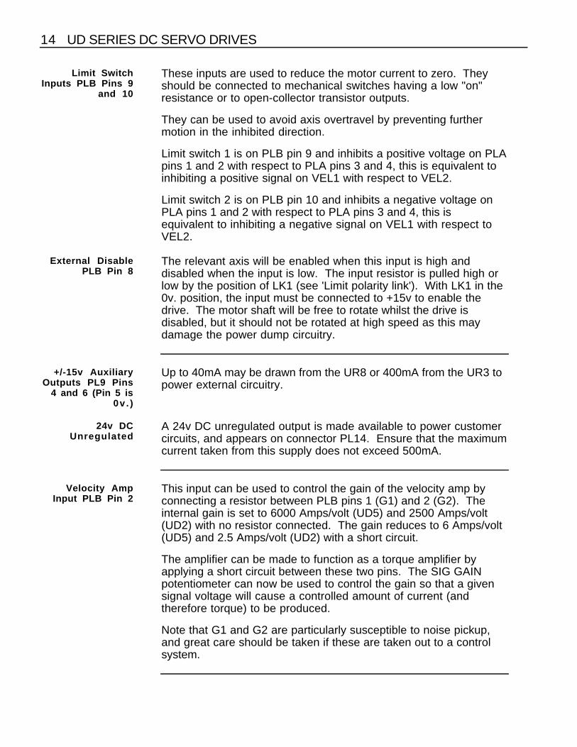
Limit SwitchInputs PLB Pins 9
and 10
These inputs are used to reduce the motor current to zero. Theyshould be connected to mechanical switches having a low "on"resistance or to open-collector transistor outputs.
They can be used to avoid axis overtravel by preventing furthermotion in the inhibited direction.
Limit switch 1 is on PLB pin 9 and inhibits a positive voltage on PLApins 1 and 2 with respect to PLA pins 3 and 4, this is equivalent toinhibiting a positive signal on VEL1 with respect to VEL2.
Limit switch 2 is on PLB pin 10 and inhibits a negative voltage onPLA pins 1 and 2 with respect to PLA pins 3 and 4, this isequivalent to inhibiting a negative signal on VEL1 with respect toVEL2.
External DisablePLB Pin 8
The relevant axis will be enabled when this input is high anddisabled when the input is low. The input resistor is pulled high orlow by the position of LK1 (see 'Limit polarity link'). With LK1 in the0v. position, the input must be connected to +15v to enable thedrive. The motor shaft will be free to rotate whilst the drive isdisabled, but it should not be rotated at high speed as this maydamage the power dump circuitry.
+/-15v AuxiliaryOutputs PL9 Pins
4 and 6 (Pin 5 is0v . )
Up to 40mA may be drawn from the UR8 or 400mA from the UR3 topower external circuitry.
24v DCUnregulated
A 24v DC unregulated output is made available to power customercircuits, and appears on connector PL14. Ensure that the maximumcurrent taken from this supply does not exceed 500mA.
Velocity AmpInput PLB Pin 2
This input can be used to control the gain of the velocity amp byconnecting a resistor between PLB pins 1 (G1) and 2 (G2). Theinternal gain is set to 6000 Amps/volt (UD5) and 2500 Amps/volt(UD2) with no resistor connected. The gain reduces to 6 Amps/volt(UD5) and 2.5 Amps/volt (UD2) with a short circuit.
The amplifier can be made to function as a torque amplifier byapplying a short circuit between these two pins. The SIG GAINpotentiometer can now be used to control the gain so that a givensignal voltage will cause a controlled amount of current (andtherefore torque) to be produced.
Note that G1 and G2 are particularly susceptible to noise pickup,and great care should be taken if these are taken out to a controlsystem.
CHAPTER 2. INSTALLATION 15
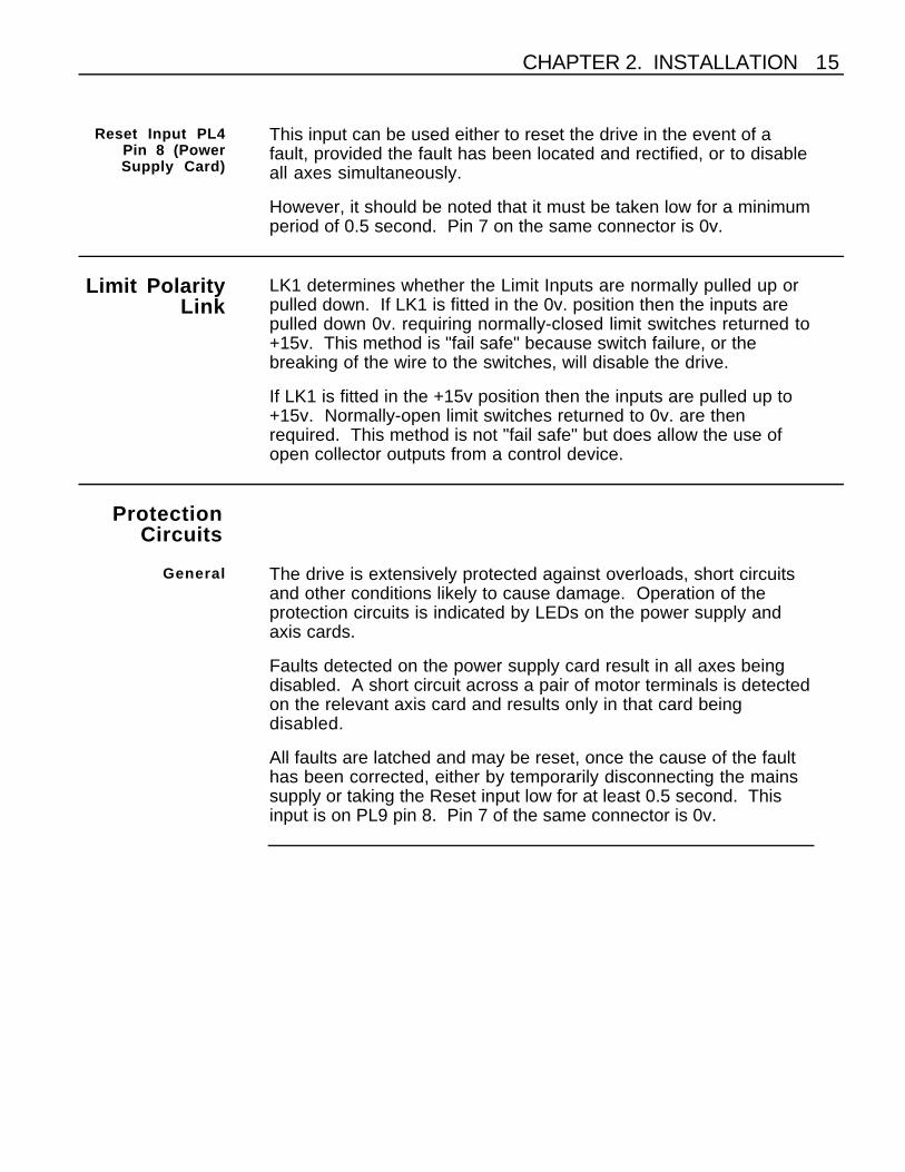
Reset Input PL4Pin 8 (PowerSupply Card)
This input can be used either to reset the drive in the event of afault, provided the fault has been located and rectified, or to disableall axes simultaneously.
However, it should be noted that it must be taken low for a minimumperiod of 0.5 second. Pin 7 on the same connector is 0v.
Limit PolarityLink
LK1 determines whether the Limit Inputs are normally pulled up orpulled down. If LK1 is fitted in the 0v. position then the inputs arepulled down 0v. requiring normally-closed limit switches returned to+15v. This method is "fail safe" because switch failure, or thebreaking of the wire to the switches, will disable the drive.
If LK1 is fitted in the +15v position then the inputs are pulled up to+15v. Normally-open limit switches returned to 0v. are thenrequired. This method is not "fail safe" but does allow the use ofopen collector outputs from a control device.
ProtectionCircuits
General The drive is extensively protected against overloads, short circuitsand other conditions likely to cause damage. Operation of theprotection circuits is indicated by LEDs on the power supply andaxis cards.
Faults detected on the power supply card result in all axes beingdisabled. A short circuit across a pair of motor terminals is detectedon the relevant axis card and results only in that card beingdisabled.
All faults are latched and may be reset, once the cause of the faulthas been corrected, either by temporarily disconnecting the mainssupply or taking the Reset input low for at least 0.5 second. Thisinput is on PL9 pin 8. Pin 7 of the same connector is 0v.

16 UD SERIES DC SERVO DRIVES
Power SupplyCard LED 1
(Lowest Position)
Illumination of this LED indicates that the motor supply has reacheda peak of above 100v DC. This condition is most likely to occur ifexcessive regeneration is taking place which may also cause thepower dump fuse to fail. Should this be the case, it will usually benecessary to fit an alternative power dump resistor which isavailable from the manufacturers.
Power SupplyLED 2
Illumination of this LED indicates a failure of the HV+7v rail which isinternally generated on the power supply card.
Power SupplyLED 3
Non-illumination of this LED indicates that either the +15v or the -15v supplies have fallen below 13.5v (typical). This may bebecause the auxiliary output is too heavily loaded by externalcircuitry, or can be the result of an internal failure.
Power SupplyLED 4
(Top Position)
Illumination of this LED indicates that the motor supply is present,and above 30v (approx). It may remain illuminated after the motorsupply has been switched off, but the intensity will decrease as thepower supply capacitors are discharged.
Axis Card LED 1(Top Position)
Illumination of this LED indicates a short circuit across the twomotor terminals or a short to ground.
Axis Card LED 2 Illumination of this LED indicates overtemperature on that drivecard.
CHAPTER 3. SETTING UP THE DRIVE 17
CHAPTER 3. SETTING UP THE DRIVE
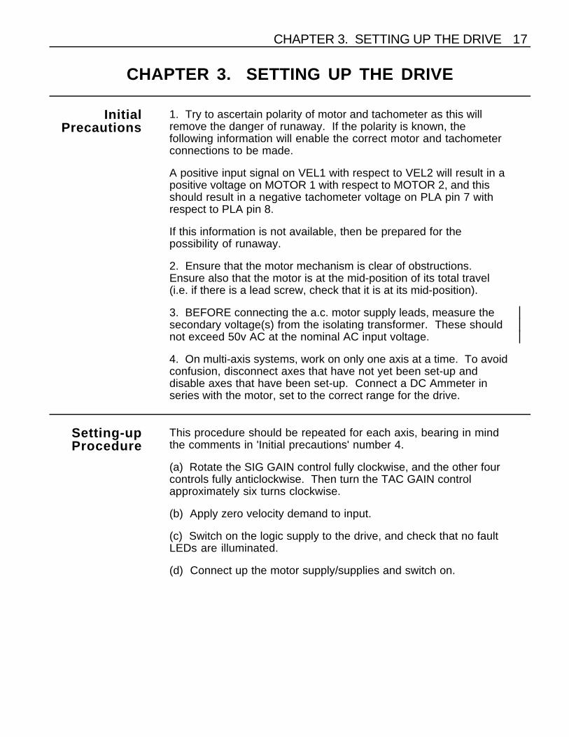
InitialPrecautions
1. Try to ascertain polarity of motor and tachometer as this willremove the danger of runaway. If the polarity is known, thefollowing information will enable the correct motor and tachometerconnections to be made.
A positive input signal on VEL1 with respect to VEL2 will result in apositive voltage on MOTOR 1 with respect to MOTOR 2, and thisshould result in a negative tachometer voltage on PLA pin 7 withrespect to PLA pin 8.
If this information is not available, then be prepared for thepossibility of runaway.
2. Ensure that the motor mechanism is clear of obstructions.Ensure also that the motor is at the mid-position of its total travel(i.e. if there is a lead screw, check that it is at its mid-position).
3. BEFORE connecting the a.c. motor supply leads, measure thesecondary voltage(s) from the isolating transformer. These shouldnot exceed 50v AC at the nominal AC input voltage.
4. On multi-axis systems, work on only one axis at a time. To avoidconfusion, disconnect axes that have not yet been set-up anddisable axes that have been set-up. Connect a DC Ammeter inseries with the motor, set to the correct range for the drive.
Setting-upProcedure
This procedure should be repeated for each axis, bearing in mindthe comments in 'Initial precautions' number 4.
(a) Rotate the SIG GAIN control fully clockwise, and the other fourcontrols fully anticlockwise. Then turn the TAC GAIN controlapproximately six turns clockwise.
(b) Apply zero velocity demand to input.
(c) Switch on the logic supply to the drive, and check that no faultLEDs are illuminated.
(d) Connect up the motor supply/supplies and switch on.
18 UD SERIES DC SERVO DRIVES
(e) SLOWLY rotate the I LIMIT control clockwise until the motorstarts to rotate. If the motor starts to accelerate towards full speed,then switch off the motor supply and check that the TAC GAINcontrol has been rotated by at least six turns clockwise. If it has,reverse the tachometer connections. If, because of system earthingand screening criteria, it would be inconvenient to change thetachometer connections, then reverse the motor connections. Don'tchange the tachometer connections as well as the motorconnections.
Switch on again and the motor should now rotate slowly.
(f) Adjust the balance control until the motor shaft rotates towardsthe positive limit. Check that the motor stops when the limit switchoperates. If it fails to stop, remove power and reverse the limitswitches. When power is re-applied, further movement should beprevented. Now rotate the BALANCE control in the oppositedirection and check operation of the negative limit switch. Returnthe axis to the centre of travel, and stop motion using the balancecontrol. Speed of return can be increased by reducing the TACHOgain.
(g) If the value of peak current is known, then this should be set upnext by locking the motor shaft and rotating the I LIMIT controlclockwise until the desired current is measured on the ammeter.This should be carried out as quickly as possible to avoid the motorand drive overheating. To assist in setting up if no ammeter isavailable, five turns clockwise gives approximately 50% peakcurrent, 10 turns gives approximately 75% peak current. If themotor runs very hot in service it may be necessary to reduce thecurrent limit setting.
(h) Rotate the TIME CON control clockwise until the motor shaftstarts to oscillate, then turn back sufficiently to stop the oscillation.Failure of the system to break into oscillation is not a problem, itusually means that the system has a high mechanical resonantfrequency.

CHAPTER 3. SETTING UP THE DRIVE 19
0 2 4 6 8 10 12 14 16 18 20
No. OF TURNS
Ip = 5A FOR UD2Ip = 12A FOR UD5Ip
0.75 Ip
0.50 Ip
0.25 Ip
PEAKCURRENT(AMPS)
Figure 5. Relationship Between I LIMIT Control and Current
(i) Periodically apply and remove the input signal (i.e. apply a stepsignal to the input), noting the response of the system. Adjust theTAC GAIN control to give the shortest settling time withoutovershoot (ignore the fact that the final speed also changes). It mayalso be necessary to turn the TIME CON control a little furtheranticlockwise if oscillation can still be heard when the motor ismoving, i.e. it sounds rough.
If the control system will not permit this method of control, removethe signal connections and use a separate DC power source, i.e. abattery or a DC power supply to provide the signal.
(j) Increase the signal gain or input signal to run the motor at highspeed (not full speed) and check for smooth behaviour. If there arestill signs of roughness try turning the TIME CON controlanticlockwise or try reducing the TAC GAIN. To optimise theresponse it is necessary to connect an oscilloscope to the Tachsignal input (PLA pin 7), the waveforms in Fig. 6 will help to indicatethe required correction. Use a small input signal when observingthese waveforms.

20 UD SERIES DC SERVO DRIVES
(k) Remove the input signal and readjust the balance control ifnecessary
(l) Finally set the SIG GAIN to give the correct speed for a giveninput signal.
TURN TACHO GAINAND/OR TIME CONST. CW
TURN TIME CONST. CW
TURN TACHO GAINAND/OR TIME CONST. CCW
TURN TIME CONST. CCWAND TACHO GAIN CW
TURN TIME CONST. CCW
IDEAL RESPONSEFOR MOST APPLICATIONS
Figure 6. Tacho Signal Waveforms

CHAPTER 4. OPERATION 21
CHAPTER 4. OPERATION
Theory ofOperation -
Axis Card
(Refer to schematic diagram Fig 7.)
LIMITCURRENT
OVER
R37
Bb = BOTTOM SWITCH bBa = BOTTOM SWITCH a
Tb = TOP SWITCH bTa = TOP SWITCH a
BALANCE
RV4
TACHO
SIGNAL
NETWORKISOLATING
ERROR AMPVELOCITY
LIMITCURRENT
CONSTANTTIME
R38 C15
0V
0V
GAINSIGNAL
R41GAIN
TACHOC17
-15V
+15V
NETWORKBALANCE
FILTER
FILTER
CCTDEFINEGAIN
Roc
HV
Tb & Bb
Ta & Ba
EXT. DISABLE
LIMIT SWITCHES
ERROR AMPCURRENT
MOTOR 0V
SENSECURRENT
BaBb
TbTa
PWM GATING
M
Figure 7. Axis Card Schematic
The axis card contains all the necessary circuitry to control a DCServo Motor. It must be used in conjunction with a Power Supplycard as this generates all the necessary voltages and includes therequired monitoring circuitry.
It can be used with a simple analogue signal source (e.g. apotentiometer), a DC Servo Motor and a tachometer. Whereverpossible the tachometer should be rigidly coupled to the motor, asflexible couplings will result in instability.

22 UD SERIES DC SERVO DRIVES
Output Stage The output stage accepts the signals from the gating section (see'Gating') and allows the flow of current in the required directionthrough the motor windings.
It consists of an H-bridge where the top and bottom switches arecontrolled in a diagonal formation i.e. the top right hand switch isturned on at the same time as the bottom left hand switch for currentflow between MOTOR 1 and MOTOR 2, the converse being true forcurrent flow in the opposite direction.
When the current has reached the desired level, the top switch willturn off, but the diagonal bottom switch will remain on. Thisprovides a low-loss recirculative loop around the bottom half of theH-bridge, i.e. one bottom switch and one bottom recirculating diodeconducting.
Both the top and bottom switches utilise active pull-off to minimiseswitching times. There is a certain amount of charge stored in thebase of the transistor, and the switch cannot turn off completely untilall this charge has gone. Using active pull-off extracts the chargequickly and this results in faster switching times.
Input Section andVelocity Error
Amplifier
The velocity demand input consists of a filtered differential inputamplifier with a gain of 0.5, which avoids saturation of the amplifiereven with inputs up to 24v. The resultant signal is passed to thesumming point of the velocity error amplifier.
The tachometer input also passes through a filter network to apotentiometer, then through anR-C network which provides a feed-forward function. This improvesthe system response to speed variations. Once again the resultantsignal is passed to the summing point of the velocity error amplifier.
The velocity error amplifier then algebraically sums the signal input,the tachometer input and the balance control input, and produces atits output a velocity error signal.
The feedback network around this amplifier is in two parts. TheTIME CON control and associated components (C15 and R38) formthe a.c. feedback network and determine the response time of thevelocity error amplifier. The gain defining network (RP3 and R35)determines the d.c. gain of the velocity error amplifier.
CHAPTER 4. OPERATION 23
The I LIMIT control does not operate directly on the output of IC1,but via an isolating network which allows the I LIMIT control toclamp the velocity error signal anywhere between +5v and ˆ5v(approximately).
Current ErrorAmplifier
The clamped output of the velocity error amplifier is thenalgebraically summed with the current feedback signal to determinethe current error. There is a bi-directional zener diode clamparound this amplifier to provide a fast slew rate by preventing theoutput stage of the amplifier from saturating.
Pulse WidthModulator
The current error is compared with a triangular waveform todetermine the switching sequence for the output stage.
The output of the P.W.M. circuit comprises two signals definingwhich of the output transistors will be on, and for how long. Thisdetermines both the direction and rate of acceleration of the motorshaft.
Gating This circuit combines the output of the P.W.M. circuit with theexternal disable signal, the enable/disable from the power supplycard and the output of the overcurrent detector. This circuittherefore determines whether a request for current from the P.W.M.circuit can be allowed to proceed further.
Current Sense The current sense circuit consists of two resistors in the currentpath, the voltage developed across the resistors being proportionalto the current flowing.
The voltage across the two resistors is fed into a filtered differentialamplifier to minimise the effects of noise and to allow calibration ofthe current feedback information.
If current is being injected into the load, or back into the motorsupply rail (i.e. during regeneration), current will only be flowing inone sense resistor. When current is flowing in the recirculativemode around the bottom half of the H-bridge, it flows through twosense resistors. This leads to double the magnitude of the currentfeedback information being available. A 'half gain' circuit isintroduced when this condition exists, thus providing correct currentinformation.
The resulting waveform is fed to the current error amplifier.

24 UD SERIES DC SERVO DRIVES
OvercurrentDetector
All current supplied from the motor supply rail passes through alow-value sense resistor. The voltage developed across thisresistor is referenced to the motor supply rail, so it is fed to a circuitthat references it to 0v. This voltage is then compared to referencevoltage and if it is greater, a latch is set, the axis is disabled andLED 1 is illuminated.
The latch may be reset either by temporarily removing the logicsupply to the drive, or by taking the RESET input on PL4 pin 8 lowfor at least 0.5 second.
Theory ofOperation -
PowerSupply Card
(Refer to schematic diagram Fig.8)
V REF
FROM TRANSFORMERAC SUPPLY
-15V+15V
HV2
HV2 +7
HV1HV1 +7
LATCHES
LED 4
LED 3
LED 2
LED 1
0V
HV PRESENT
LOGIC SUPPLY PRESENT
SUPPLY FAILURE
HV OVERVOLTAGE
ENABLE TO DRIVE CARDS
RESETINITIAL
DETECTORFAULT
DETECTORFAULT
DETECTORFAULT
PSU
0V24V UNREGULATED-15VLOGIC 0V+15V+7V(W.R.T.HV2)+7V(W.R.T.HV1)
EXT RESET
DUMPCOMPARE
INPUTSSUPPLY
AC
HV1
HV2
Figure 8. Power Supply Card Schematic
CHAPTER 4. OPERATION 25
The same power supply card is used on both the single and dualvoltage sub-racks.
This card comprises the power supply, fault logic and power dumpcircuitry. It generates all the voltages required to drive the axiscards, provides the supply rails for the active pull-off, monitors thepower supply rails for faults and operates the power dump circuit inthe event of excessive regeneration.
Logic Supply The logic supplies are generated by taking the 18v-0-18v RMSsupply, rectifying, smoothing, and regulating it via the tworegulators. These supplies are used internally in the power supplycard, and also made available on PL9 which is on the motherboard.
A 5.1 volt reference is also generated and this is used by the faultdetection circuitry.
Active Pull-offSupply
Generation
Two 7v DC (approx) supplies are also generated on this board.The negative of each supply is connected to one of the two HV rails,thus creating the HV1+7v and HV2+7v pull-off rails.
Fault Monitoring The motor supply is monitored by comparing it (via a potentialdivider) with the 5.1v reference. If it exceeds a value determined bythe potential divider then a latch will be set, LED 1 will beilluminated and the enable will be removed from all the axis cards.
The presence of the pull-off supply is also detected, since absenceof these supplies during operation will seriously damage the unit. Ifthey are not present then a latch is set, LED 2 is illuminated and theenable will be removed from the axis cards.
Both the positive and negative Logic Supply rails are monitored bycomparing them (via a potential divider) with the 5.1v reference,and if either of them falls below predetermined values set by thepotential dividers then a latch is set, LED 3 is extinguished and theenable is removed from the axis cards.
26 UD SERIES DC SERVO DRIVES
Enable/ResetCircuitry
The PSU FAULT (PL9 pin 10) is the result of OR-ing the faultlatches on the Power Supply card, and is low when a fault occurs.It may be used to drive external circuitry, and can sink a maximumof 100mA.
The READY signal (PL9 pin 9) is itself the OR function of threesignals, the RST signal from PL9 pin 8, an INTERNAL FAULT signaland the PSU fault signal which ensures that all fault latches arereset at power-on. The power-on reset signal also allows for allsupply rails to be established before the axis cards are enabled.
Power DumpCircuit
This circuit is a standard feature on the UD system and ensures thatthe motor supply rail does not rise excessively during regeneration.It does this by comparing the actual supply rail value with a"calculated" value. This calculated value is obtained simply byrectifying the incoming AC Motor Supply rails. When the actualvalue exceeds the calculated value by a preset amount, then adump resistor is switched into circuit to dissipate the excess energy.The circuit also discharges the HV capacitor at power-down.
As mentioned in 'Single-voltage supply connection', excessiveregeneration may cause LED 1 to be illuminated or even cause thedump fuse to blow. Fitting an external alternative dump resistorprovides for a greater power dissipation. In addition themanufacturers can supply a power supply card which has anincreased dump capacity which must be used with the externaldump resistor.
CHAPTER 5. TROUBLESHOOTING 27
CHAPTER 5. TROUBLESHOOTING
General In order to minimise field failures all UD drives are soak tested atelevated temperatures. In spite of this the occasional failure maystill occur, and the following notes are intended as a brief guide toenable the cause of the fault to be located.
ModuleRemoval andReplacement
Removal of axis cards and power supply cards from the sub-rack iseasily achieved by removing the front panel and unplugging themodule. Ensure that all supplies are switched off, and allow timefor the supplies to collapse.
PowerSupply Card
The majority of faults that can occur on this card will result inillumination of one or more of the LEDs, fault diagnosis on this cardwill therefore be listed under the relevant LED.
LED 1 (Red):Lowest Position
Failure of the dump circuit to cope with regeneration may result inthis LED being on. Check if the fault occurs during a period ofdeceleration, if so then consult manufacturers regarding increasingthe dump capability. Ensure that the supply rail normally has avalue of less than 75V DC.
Check the dump fuse.
LED 2 (Red) Check the drive fuses, FS1 to FS3 on UR3 racks and FS1 to FS8on UR8 racks. These fuses are fitted on the inside of themotherboard and are accessible by removing the axis cards (see'Module removal and replacement').
If the active pull off rail is missing then this LED will be on.Confirmation of this can be obtained by removing all the axis cards.Switch on the logic supply and the HV supply, if LED 2 is stillilluminated then the power supply card is probably faulty. Toconfirm the cause, remove the power supply card and replace withanother. If the fault is no longer apparent, then it is the powersupply card that is at fault and it should be returned for repair.
28 UD SERIES DC SERVO DRIVES
LED 3 (Green) Non-illumination of LED 3 indicates a logic supply fault, and checksshould first be made that excessive current is not being drawn fromthe +/-15v auxiliary outputs (PL9 pins 4 and 6). The maximumpermitted load is 400mA (UR3), or 40mA (UR8). Check also thatthe 18v-0-18v AC supply is not low due to the 24v unregulatedsupply being overloaded (maximum 500mA).
If neither of these is the cause of the fault indication, then the faultwould appear to lie with either an axis card or with the powersupply card itself. To eliminate the cards which are not responsibleproceed as follows:
(a) Switch off all supplies and allow time for the supplies tocollapse.
(b) Remove all axis cards.
(c) Switch on the logic supply ONLY.
(d) If LED 3 is still not illuminated then the fault lies with the powersupply card.
(e) If it is, then the problem lies with one of the axis cards and thefaulty card can be discovered by repeating the procedure, witheach axis card connected in turn.
(f) It is possible that these tests will show that it is the number ofaxis cards connected that causes the fault, in which case the faultlies with the power supply card.
LED 4 (Green) This LED indicates that HV is present. It will remain illuminated fora short time after HV has been switched off, because of the storedcharge in the capacitors.
Axis Card Faults associated with the axis card will either result in theillumination of the Overcurrent LED, or the Overtemperature LED.
Overcurrent LEDIllumination
This LED will be illuminated in the event of a short circuit occurringbetween the motor terminals. It may also occur if either terminal isshorted to earth, either by arcing from the brushes or by a moredirect connection.

CHAPTER 5. TROUBLESHOOTING 29
If no external reason can be found then further tests will benecessary to establish the exact cause. Switch off all supplies,then remove the associated motor connections from themotherboard. Switch on the Logic Supply and then the MotorSupply. If the Overcurrent fault LED is now illuminated then theaxis card is at fault and should be returned to the manufacturers forrepair. It may be necessary to request motion in either direction toobtain the fault. If the LED does not come on then additionalchecks can be carried out with an ohmmeter.
Switch off all supplies and remove the suspect axis card. Using theohmmeter check between each of the motor supply connectionsand each motor terminal (2a and c and 4a and c on the axis cardedge connector). The reading should either be a high impedanceor the equivalent of one diode voltage drop. Reversing the polarityof the ohmmeter leads should result in a similar set of readings, butif the first reading was high impedance then the reading with thepolarity reversed will be a diode voltage drop. If this is not the case,i.e. either a short circuit, or a diode voltage drop is obtained in bothcases, then one or more of the transistors in the H-Bridge isdamaged and the axis card should be returned for repair.
If previous tests have not enabled the fault to be isolated thensubstitution of the cards should enable the fault to be narroweddown to one card which can then be returned for repair.
OvertemperatureLED Illumination
This LED indicates an overtemperature fault. It may be the result ofan axis card fault, which can of course be proved by substitution. Ifthis does not identify the fault then checks should be made toensure that the ambient temperature does not exceed 50°C, whenall units in the vicinity of the drive have reached their normaloperating temperature. A cooling fan may be necessary if high dutycycles are required.
IncorrectOp eration
Noise from Motoror Unstable Motor
Operation
This is usually caused by TAC GAIN or TIM CON controls beingturned too far clockwise. Re-adjustment of either of these twocontrols should cure this, but if not then check that the motor-to-tachometer coupling is not defective. If none of these checks hasisolated the problem then substitution of cards should be used toprove whether or not the axis card is at fault.
Motor Runaway This can be caused either by the tachometer connections beingbroken, by them being reversed, or by the TAC GAIN control beingturned too far anticlockwise. First turn the TAC GAIN controlclockwise to ascertain whether this cures the fault. If not then checkthe leads for integrity and if the fault persists reverse the
30 UD SERIES DC SERVO DRIVES
connections. If none of these steps cures the fault then substitutionof modules can be used to prove if the axis card is faulty.
No Movement inOne Direction
Check that there is no mechanical reason for the inability to move inone direction. Check also that the limit switch inputs (PLB pins 9and 10) are not low as this will prevent movement in one direction.
If these checks do not locate the fault, then substitution of themodule may prove if the axis card is faulty.
Motor Creep This is usually caused by an incorrect setting of the BALANCEcontrol, so first check this setting by turning the SIG GAIN controlfully clockwise and confirming that there is zero velocity commandon VEL1 and VEL2 inputs. Then adjust the BALANCE control untilthe motor shaft is stationary.
Ensure that any unused signal inputs are grounded to avoid pickup,and that all signals are supplied in twisted pairs or screenedcables.
If none of these steps resolves the problem then, once again, trysubstitution of the axis card to prove if the module is at fault.
Returningthe System
Contact the Parker Automation Technology Centre or themachinery manufacturer who supplied the product. Equipment forrepair should NOT be returned directly to Digiplan without priorauthorisation. Repairs will be carried out by Digiplan but will beprocessed via your supplier.
Digiplan may at their discretion authorise direct shipment to andfrom Poole or Rohnert Park, but only by prior arrangement with yoursupplier. Existing UK and USA customers who purchaseequipment directly from Digiplan should contact Poole or RohnertPark for further information (contact numbers are at the front of thisUser Guide).
INDEX
Auxiliary outputs 14
Balance control 18
Control signals 13Current error amplifier 23
Current sense 23
Disconnect device 7Dual-voltage rack 4
Enable/reset circuitry 26External disable 14

INDEX 31
Fault monitoring 25Fuse ratings 12
Gating 23
I LIMIT control 18Installation 5Isolating transformer 6
Limit polarity link 15Limit switch inputs 14Line fuse type 7Line fuse values 7Logic supply 12, 25
Module removal 27Motor connections 13Motor creep 30Motor runaway 30Motor supply 6
Noise from motor 29
Overcurrent detector 24Overcurrent LED 28Overtemperature LED 29
Peak current 18Power dump circuit 26
Power supply 16Precautions 17Protection circuits 15Pulse width modulator 23
Rese input 15
Setting-up procedure 17SIG GAIN control 17Signal connections 13Signal input 13Single voltage rack 5
TAC GAIN control 17Tachometer input 13Theory of operation 21TIME CON control 18Troubleshooting 27
Unstable motor operation 29
Variant information 4Velocity amp Input 14Velocity error amplifier 22