udc 621.887.6 621.824 001.4 003.62 620.1 deuts ch e … · circlips within the meaning of this ......
TRANSCRIPT

UDC 621.887.6 : 621.824 : 001.4 : 003.62 : 620.1 DEUTS CH E NORM September 1981
Circlips (retaining rings)
I 471 for shafts
Normal type and heavy type
Sicherungsringe (Halteringe) für Wellen; Regelausführung und schwere Ausführung
Supersedes DIN 471 Part 1/03.65 and DIN 471 Part 2/03.65 and partially supersedes DIN 995/01.70
As it is current practice in standards published b y the International Organization for Standardization (ISO), the comma has been used throughout as a decimal marker.
Dimensions in mm
Contents Page
1 Concept . . . . . . . . . . . . . . . . . . . . . . . . . . . . . . . . . . . . . 1 2 Dimension letters, symbols . . . . . . . . . . . . . . . . . . . . . . . . . 1 3 Dimensions, designation, design data . . . . . . . . . . . . . . . . . . 2 4 Material . . . . . . . . . . . . . . . . . . . . . . . . . . . . . . . . . . . . . 6 5 Finish.. . . . . . . . . . . . . . . . . . . . . . . . . . . . . . . . . . . . . . 6 6 Testing.. . . . . . . . . . . . . . . . . . . . . . . . . . . . . . . . . . . . . 7 7 Load-bearing capacity . . . . . . . . . . . . . . . . . . . . . . . . . . . . 8 8 Detachmentspeed . . . . . . . . . . . . . . . . . . . . . . . . . . . . . . 9 9 Shape of groove . . . . . . . . . . . . . . . . . . . . . . . . . . . . . . . 1 O
10 Fitting the circlip . . . . . . . . . . . . . . . . . . . . . . . . . . . . . . 10
1 Concept Circlips within the meaning of this standard are retaining rings for holding structural components (e.g. rolling bearings) on shafts. They are given an eccentric shape, are fitted with spring retention in grooves and are suitable for the trans- mission of axial forces (see in this respect clause 7).
2 Dimension letters, symbols radial width of the lug beam (radial width of circlip opposite the aperture) distance between measuring plates for testing spiral flatness shaft diameter groove diameter internal diameter of circlip not under tension maximum symmetrical diameter of bore during fitting diameter of the lug holes modulus of elasticity load-bearing capacity of groove at a yield point of the grooved material of 200 N/mm2 (see subclause 7.1 ) load-bearing capacity of circlip with sharp-edged abutment of the pressing part (see subclause 7.2) load-bearing capacity of circlip for abutment with edge chamfering distanceg (see subclause 7.2) yield point edge chamfering distance of the abutment surface to the circlip distance between the plates when testing conical deformation groove width edge margin detachment speed of the circlip (see clause 8) curvature in the groove base or test jaws thickness of the circlip groove depth with nominal sizes of dl and d2 Continued on pages 2 to 12
Sole 8818 rights of German Standards (DIN-Normen) are with Beuth Verlag GmbH. Beriin 30 07.82 DIN 471 Engl. Price group 9
Saler No. O 1 0 9
Copyright Deutsches Institut Fur Normung E.V. Provided by IHS under license with DIN
Not for ResaleNo reproduction or networking permitted without license from IHS
--`,,,,-`-`,,`,,`,`,,`---

Page2 DIN 471
3 Dimensions, designation, design data The circlips do not need to conform to the illustration; only the dimensions specified must be adhered to.
unloaded
shape of ring at manufacturer’s discretion
External clearance
Figure 1.
di s 9 m m
-4% Figure 2.
Detail of x di > 9 300mm di’ 170mm
a t manufacturer‘s discretion
I pdJ 141
Figure 3.
Values for peak-to-valley height for groove base and loaded edge must be specified in each case. Designation of a circlip for shaft diameter (nominal dimension) dl = 40 mm and circlip thickness = 1.75 mm:
Circlip DIN 471 - 40 x 1,75
Copyright Deutsches Institut Fur Normung E.V. Provided by IHS under license with DIN
Not for ResaleNo reproduction or networking permitted without license from IHS
--`,,,,-`-`,,`,,`,`,,`---

DIN 471 Page3
Shaft Clip diam- eter
Weight of 1000
S d3 a b l ) 4 pieces d l
limen- per per. ominal in kg
sion dev. dev. man. % mln.
Table 1. Normal type
Groove Supplementary data 4)
Nominal size
d i 2 ) m 3 ) n d4 FN FR g FRC h i according of pliers
to Per kN min-1 DIN 5254 dev H13 rnln. kN kN
Copyright Deutsches Institut Fur Normung E.V. Provided by IHS under license with DIN
Not for ResaleNo reproduction or networking permitted without license from IHS
--`,,,,-`-`,,`,,`,`,,`---

Page4 DIN471
Shaft dam- eter
d l
Nmninal dimen-
sion
72
Table 1. (continued)
I
Clip Groove
Weight Of 1000
d3 a b ' ) d5 pieces d22) m31 t in kg
per per. dev. dev. m a . min. %
2.5 67.5 8.2 6.8 3 22.5 69
mln. 1 75 12,51 i 8,41 7 13 1 i i5 78 2.5 -:,o7 73,5 io.46 8.6 7.3 3
80 2.5 74.5 8.6 7.4 3 27.3 76.5
Nominal size
of pliers
to kN kN kN min-' DIN 5254
d4 FN 8 FR. '.bl according
82 I 2.5 1 I 76,5 8.7 I 7,6 13 I 31.2 I 78.5 85 3 79.5 8.7 I 7.8 13.51 36.4 I 81.5
12.65 I 1.5
12,6511,75
13.1511.75
I Supplementary data 4)
4.5 I 89.2 1 55.30 1131.8 12.51 22.8 [ 6190
1108.5 ~ 80,80 217.2
13 134.4 i 1;; 1 5.3 114,8 85.50 212.2 3.5 29.25 4550
5,3 120,2 90,OO. 206.4 3,5 29.0
125.8 107.6 471.8 3.5 67.7
40
5.3 100.3 73.50 128.0 3 19.6 5860
5,3 103.3 76.20 215.4 3 33.4 5710
5.3 106.5 79.00 221.8 3 34.85 5200
85
6 131.2 113.0 457.0 3.5 66.9 4340
6 137.3 118.2 438.6 3.5 65.5 3970
6 143.1 123.5 424,6 3,5 64.5 3685
1149 1128,7 1411,514 156,5 134341 154.4 134.0 395.5 4 55,2
159.8 139.2 389.5 4 55.4
6 165.2 144.5 376.5 4 54.4 2760
6 I 170.6 1 149.6 1367.0 14 I 53.8 I 2600
7.5 I 177.3 I 193.0 1357.5 I4 I 53.4 I 2480
7,5 I 182,3 1 199.6 1 352.9 14 I 52.6 I 2710
7.51188 1206.1 1349.214 152.2 I 2540
7.5 193.4 212.5 1345.3 5 41.4 2520
7.5 198.4 219.1 1349.2 5 41.9 2440
7.5 203.4 225.5 1340.1 5 40.7 2300
7,51210 1232.2 1345,315 i41.4 I 2180 I 7.51 215 1238.6 i 336.715 140.4 I 2070 I
125
I For I ) , 2). 3) and 4) see page 3
Copyright Deutsches Institut Fur Normung E.V. Provided by IHS under license with DIN
Not for ResaleNo reproduction or networking permitted without license from IHS
--`,,,,-`-`,,`,,`,`,,`---

DIN471 Page5
Table 2. Heavy type
dl Nominal dimen- per, sion I dey
18 1,5 -:pt
20 1,75
22 1.75
Clip Groove 7 d3 a
- OP2
32.2 6.7
55.8
-1.1
74.5
Weight Of 1000
in kg dev
9 13.51 71,6 I 96.5 I
2.65 11
Supplementary data4)
1
d4 FN FR g FR#
I kN ~ min-’ kN kN
For I ) , 2). 3) and 4) see page 3
Note: d 4 calculated from: d 4 = dl + 2.1 a
Copyright Deutsches Institut Fur Normung E.V. Provided by IHS under license with DIN
Not for ResaleNo reproduction or networking permitted without license from IHS
--`,,,,-`-`,,`,,`,`,,`---
Page6 DIN471
-
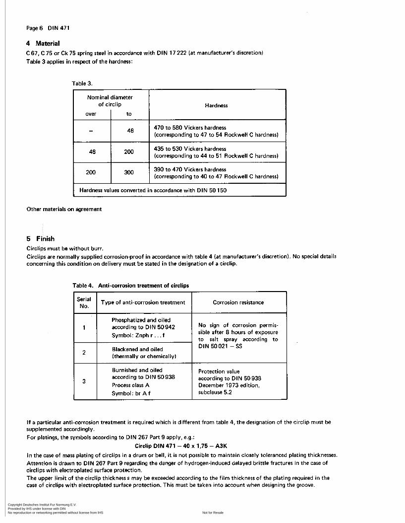
48
4 Material C 67, C 75 or Ck 75 spring steel in accordance with DIN 17 222 (at manufacturer's discretion) Table 3 applies in respect of the hardness:
470 to 580 Vickers hardness (corresponding to 47 to 54 Rockwell C hardness)
435 to 530 Vickers hardness (corresponding to 44 to 51 Rockwell C hardness)
48
200
Table 3.
Type of anti-corrosion treatment
Phosphatized and oiled according to DIN 50942 Symbol: Znph r . . . f
Blackened and oiled (thermally or chemically)
No.
1
2
7
Corrosion resistance
No sign of corrosion permis- sible after 8 hours of exposure to salt spray according to DIN 50021 -SS
Nominal diameter of circlip
over I to
Burnished and oiled according to DIN 50 938 Process class A Symbol: br A f
3
Hardness
Protection value according to DIN 50 938 December 1973 edition, subclause 5.2
390 to 470 Vickers hardness (corresponding to 40 to 47 Rockwell C hardness)
200 I 300 I Hardness values converted in accordance with DIN 50 150
Other materials on agreement
5 Finish Circlips must be without burr. Circlips are normally supplied corrosionproof in accordance with nufacturer's discretion). No special details concerning this condition on delivery must be stated in the designation of a circlip.
able 4 (a t m
I f a particular anti-corrosion treatment i s required which i s different from table 4, the designation of the circlip must be supplemented accordingly. For platings, the symbols according to DIN 267 Part 9 apply, e.g.:
Circlip DIN 471 - 40 x 1.75 - A3K
In the case of mass plating of circlips in a drum or bell, it i s not possible to maintain closely toleranced plating thicknesses. Attention i s drawn to DIN 267 Part 9 regarding the danger of hydrogen-induced delayed brittle fractures in the case of circlips with electroplated surface protection. The upper limit of the circlip thickness may be exceeded according to the film thickness of the plating required in the case of circlips with electroplated surface protection. This must be taken into account when designing the groove.
Copyright Deutsches Institut Fur Normung E.V. Provided by IHS under license with DIN
Not for ResaleNo reproduction or networking permitted without license from IHS
--`,,,,-`-`,,`,,`,`,,`---

DIN471 Page7
Nominal diameter Force F in N f 5 %
Normal Heavy of circlip
over to type type
- 22 30 60
22 38 40 80 38 82 60 120
6 Testing 6.1 Testing the material Vickers hardness test in accordance with DIN 50 133 Part 1 Rockwell hardness test in accordance with DIN 50 103 Part 1 In cases of doubt, the Vickers hardness test applies.
h - s
max.
b X 0,03
6.2 Bend and fracture test The testing of the circlip for ductility must be carried out in accordance with figure 4.
82 150
Figure 4. Bend test
I b X 0,02 150 80 160
300 150 300
One half of the circlip is clamped between two jaws, of which one has a radius equal to the thickness of the circlip. The circlip i s bent through 30" by repeated light hammer blows or with a lever, following which there must be no fractures or cracks in the circlip. The circlip is then further bent until fracture occurs. The fracture surface must reveal a fine-grained structure.
6.3 Testing the deformation 6.3.1 Testing the conical deformation The circlip is placed between two parallel plates and loaded in accordance with figure 5. The distance h -s measured under force F must not exceed the maximum value stated in table 5.
Figure 5. Testing the conical deformation
Copyright Deutsches Institut Fur Normung E.V. Provided by IHS under license with DIN
Not for ResaleNo reproduction or networking permitted without license from IHS
--`,,,,-`-`,,`,,`,`,,`---

Page8 DIN471
Nominal diameter of circlip
over to
- 1 O0 1 O0 -
6-32 Testing the spiral flatness The circlip must fal l through t w o parallel, perpendicular plates w i th a clearance c in accordance w i th table 6.
C
1,5 X s
1.8 X s
Table 6.
7
Acceptable quality level AQL 1)
for testing of features for testing for faulty parts
1 1 3
1) See DIN 40080
Figure 6. Testing the spiral flatness
6.4 Testing the function (permanent set and grip test) The circlip is passed five times over a cone with a diameter o f 1 ,O1 dl in accordance w i th figure 14 and must then be f i t ted onto a bo l t of minimum groove diameter d2 where it must remain under its own weight.
6.5 Acceptance testing For the acceptance testing the principles for testing and acceptance in accordance w i th DIN 267 Part 5 apply. Table 7 applies t o the features, while table 8 applies for the acceptable quality level.
Table 7.
Features
Circlip thickness s Circlip internal diameter d3 Conical deformation Spiral flatness Function (set and grip)
Table 8.
7 Load-bearing capacity A circlip connection requires separate calculations for the load-bearing capacity of the groove FN and for the load-bearing capacity of the circlip F R . In each case the weaker part is that which applies. The load-bearing capacities (FN, F R , FRg) listed in clause 3 contain no safety neither against yielding under static stress nor against fatigue fracture under fluctuating stress. There is a t least twice the level of safety against fracture under static stress.
Copyright Deutsches Institut Fur Normung E.V. Provided by IHS under license with DIN
Not for ResaleNo reproduction or networking permitted without license from IHS
--`,,,,-`-`,,`,,`,`,,`---
DIN471 Page9
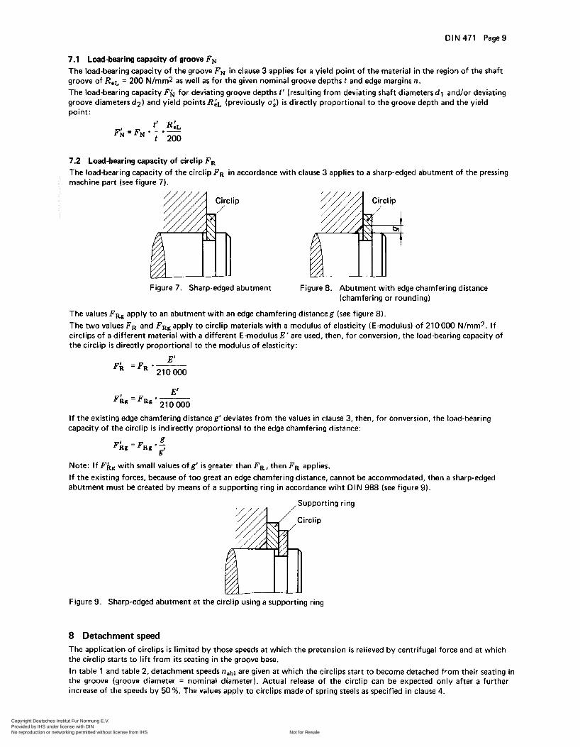
7.1 Load-bearing capacity of groove FN The load-bearing capacity of the groove F N in clause 3 applies for a yield point of the material in the region of the shaft groove of Re, = 200 N/mmz as well as for the given nominal groove depths t and edge margins n. The load-bearing capacity F# for deviating groove depths t' (resulting from deviating shaft diameters dl and/or deviating groove diameters d 2 ) and yield points R&, (previously u:) i s directly proportional to the groove depth and the yield point:
7.2 Load-bearing capacity of circlip F R The load-bearing capacity of the circlip FR in accordance with clause 3 applies to a sharp-edged abutment of the pressing machine part (see figure 7).
Figure 7. Sharp-edged abutment Figure 8. Abutment with edge chamfering distance (chamfering or rounding)
The values FR, apply to an abutment with an edge chamfering distanceg (see figure 8). The two values FR and FRg apply to circlip materials with a modulus of elasticity (E-modulus) of 210000 N/rnm*. If circlips of a different material with a different E-modulusE'are used, then, for conversion, the load-bearing capacity of the circlip i s directly proportional to the modulus of elasticity:
E' F;L = F R * -
21 o O00
If the existing edge chamfering distanceg' deviates from the values in clause 3, then, for conversion, the load-bearing capacity of the circlip is indirectly proportional to the edge chamfering distance:
Note: I f Fhg with small values of g' is greater than F R , then F R applies. If the existing forces, because of too great an edge chamfering distance, cannot be accommodated, then a sharp-edged abutment must be created by means of a supporting ring in accordance wiht DIN 988 (see figure 9).
Figure 9. Sharp-edged abutment a t the circlip using a supporting ring
8 Detachment speed The application of circlips i s limited by those speeds at which the pretension is relieved by centrifugal force and at which the circlip starts to lift from i t s seating in the groove base. In table 1 and table 2, detachment speeds nab1 are given a t which the circlips start to become detached from their seating in the groove (groove diameter = nominal diameter). Actual release of the circlip can be expected only after a further increase of the speeds by 50%. The values apply to circlips made of spring steels as specified in clause 4.
Copyright Deutsches Institut Fur Normung E.V. Provided by IHS under license with DIN
Not for ResaleNo reproduction or networking permitted without license from IHS
--`,,,,-`-`,,`,,`,`,,`---

Page 10 DIN 471
9 Shape of groove 9.1 Groove diameter d2
The groove diameters d2 specified in clause 3 are selected so that the circlips are seated in the groove with pretension. Note: Smaller groove diameters are possible if pretension can be dispensed with. The lower limit is; dz min. = d3 max.
9.2 Groove width m As a rule, for the groove widths specified in table 1 and table 2, the tolerance zone H13 applies. With unilateral power transmission, the grooves can be widened and/or chamfered towards the unloaded side. The groove width has no influence on the load-bearing capacity of the circlip connection. Intra-plant specified groove shapes and groove widths are therefore possible. If the circlip i s to be subjected to alternate power transmission on both groove edges, the groove width m must as far as possible, e.g. also by reducing the tolerance, be matched to the circlip thickness. (For groove shapes, see figure 10 to figure 13).
Figure 10.
Figure 12.
Figure 11.
Figure 13.
9.3 Shape of groove base A square shape i s the normal type of groove base (see figure 10). The radius r on the load side must not exceed 0.1 s. Other successful shapes of groove are shown in figure 1 1 to figure 13. In the case of a sharp-edged square groove, the notch sensitivity of the material used produces a corresponding fatigue notch factor.
10 Fitting the circlip Pliers in accordance with DIN 5254 shall be preferred for fitting the circlips. When fitting, make absolutely sure that the circlips are not overspread, ¡.e. are not opened further than i s necessary for fitting over the shaft. If necessary, pliers with opening restriction (set screw) shall be used. The safest protection against overspreading i s fitting with the aid of cones (see figure 14).
Pressure sleeve Cone Circlip
Centering Groove Shaft
Figure 14. Fitting with cones
Copyright Deutsches Institut Fur Normung E.V. Provided by IHS under license with DIN
Not for ResaleNo reproduction or networking permitted without license from IHS
--`,,,,-`-`,,`,,`,`,,`---

DIN 471 Page 11
Standards referred to DIN 267Part5
DIN 267Part9 DIN 988 DIN 5254 DIN 17222 DIN 40080 DIN 50021 DIN 50 103 Part 1 DIN 50 133 Part 1
DIN 50 150
DIN 50938 DIN 50942
Bolts, screws, nuts and similar threaded and formed parts; technical conditions of delivery; testing and acceptance Mechanical fasteners; technical conditions of delivery; components with electroplated coatings Shim rings and supporting rings Pliers for circlips for shafts Cold rolled steel strips for springs; technical conditions of delivery Procedures and tables for sampling test using qualitative features (sampling by attributes) Corrosion tests; spray tests with different sodium chloride solutions Testing of metallic materials; Rockwell hardness testing, C, A, B, F methods Testing of metallic materials; Vickers hardness testing, test load range: 49 N to 980 N (5 kp to 100 kp) Testing of steel and cast steel; conversion table for Vickers hardness, Brinell hardness, Rockwell hardness and tensile strength Burnishing of iron material; principles of methods, symbols, testing Phosphatizing of metals; procedural principles, symbols and test methods
Further standards DIN 472 Circlips (retaining rings) for bores; normal type and heavy type DIN 983 Circlips with lugs (retaining rings) for shafts DIN 984 Circlips with lugs (retaining rings) for bores DIN 5256 Pliers for circlips for bores DIN 6799 Lock washers for shafts
Earlier editions DIN 471 : 12.41,11.42,01.52,01.54; DIN 471 and 472 Supplement 1 : 01.45,03.54x; DIN 471 Part 1: 03.65; DIN 471 Part 2: 03.65; DIN 995: 01.70
Amendments The following amendments have been made as compared with DIN 471 Part 1, March 1965 edition, DIN 471 Part 2, March 1965 edition and DIN 995, January 1970 edition: a) standards combined b) contents revised and extended (see Explanations).
Explanations The present revised edition of DIN 471 supersedes DIN 471 Part 1 and Part 2 and parts of DIN 995 where these concern circlips for shafts. This inclusion of several standards within one standard and supplemented by technical delivery con- ditions and guidelines for fitting has produced a whole and complete standard which can be applied without the simul- taneous application of additional standards. The following explanations are given with respect to this Standard.
Re Title The term "(retaining rings)" has been added to the t i t l e of the standard. The old designation "circlips" has been retained, although these components are used only for the axial retention of components on shafts and have no locking action. The organizational problems associated with a general change in designation desirable for the sake of clarity were, because of the wide distribution of these standards, also rated as more important than the danger of misunderstood information on the part of the standards user due to an inappropriate tit le.
Re Clause 1 Concept This clause was included in order to prevent possible errors in the application and function of the parts resulting from the designation.
Re Clause 2 Dimension letters, symbols Clause 2 l ists and describes the dimension letters and symbols used in the standard.
Copyright Deutsches Institut Fur Normung E.V. Provided by IHS under license with DIN
Not for ResaleNo reproduction or networking permitted without license from IHS
--`,,,,-`-`,,`,,`,`,,`---

Page 12 DIN 471
Re Clause 3 Dimensions, designation, design data This clause contains the dimensions of the circlips of normal type and heavy type. Required design data have been added. The dimensions of the circlips or their tolerances have been corrected slightly in a few cases without any danger thereby of replacement difficulties. Two types of circlip shape have been shown. The second type of circlip shape included as an additional option has been used for some years. In certain fields it has manufacturing advantages. The application and function of the circlips do not differ from the type previously represented in this standard (lefthand illustration). Toleranced dimensions for the shape and position of the shaft groove have been included a t the request of the userS.These specifications apply to the general application of circlips. Other internal specifications may be used for individual cases. In the main, this applies also to the'groove surfaces for which no generally valid regulations were able to be given in this standard. The possibility of reducing the number of types of circlips, also possibly by means of main and subsidiary series for the shaft diameters, has been thoroughly examined. But no technically feasible solution was able to be found, since practically al l sizes with varying datum points are in use as a result of the already mentioned wide range of application. It was also not possible to offer a selection according to rolling bearing diameters.
Re Clause 4 Material Details of the material have been modified. Three materials have been selected as the most usual from DIN 17 222. Other materials must be agreed by the parties concerned.
Re Clause 5 Finish Details of the finish have been extended and adapted to present conditions. With electroplated circlips, the danger of hydrogen embrittlement is relatively great and requires special attention within the meaning of DIN 267 Part 9. Particular reference hastherefore been made to DIN 267 Part9. Accordingto this standard, the situation i s approximately asfollows: In order to avoid hydrogen-induced delayed brittle fractures in the electroplated surface protection of circlips, the galvanic treatment and heat treatment before and after electroplating must be selected so that only a small amount of hydrogen is taken up in the pickling and galvanic treatment and this hydrogen is furthermore driven off again to a large extent. Normally, delayed brittle fractures can be avoided by these measures. If brittle fractures must be avoided with specific, statistical certainty, the taking of appropriate quantities of random samples i s recommended followed by fatigue testing of these samples over 48 hours at room temperature; the circlips must thereby be loaded up to the shaft diameter dl .
Re Clause 6 Testing Clause 6 covering the testing of circlips is new to the standard. It specifies tests which are required for the assessment of the mechanical and functional properties of circlips. The contents of this clause results from the experience of manu- facturers and users and correspond to the general applications for circlips. This also applies to the details of acceptance testing given in subclause 6.5. These details are based on DIN 267 Part 5. Special agreements are not thereby excluded.
Re Clause 7 Load-bearing capacity Clause 7 containsdetails of the calculation of the load-bearing capacities of circlips and indicates how the extended data given in tables 1 and 2 have arisen. These data refer only to normal applications but clause 7 gives the priciples for calculating the load-bearing capacities also for other applications.
Re Clause 8 Detachment speed Clause 8 is supplementary to clause 7 and explains the detachment speeds in tables 1 and 2.
Re Clause 9 Shape of groove Various possibilities are presented in clause 9 for the shape of the grooves for circlips and these are also applicable from an economic standpoint. Decisions on appropriate shapes must be made on an individual basis.
Re Clause 10 Fitting the circlip Clause 10 recommends the use of cones for fitting circlips. This type of fitting i s of particular advantage in bulk manu- facturing.
Copyright Deutsches Institut Fur Normung E.V. Provided by IHS under license with DIN
Not for ResaleNo reproduction or networking permitted without license from IHS
--`,,,,-`-`,,`,,`,`,,`---