udp hole punching in tomp2p for nat traversal - uzh · udp hole punching in tomp2p for nat...
TRANSCRIPT

UDP Hole Punching in TomP2P forNAT Traversal
Jonas WagnerEmmenbrücke, SchweizStudent ID: 11-716-230
Supervisor: Dr. Tomas Bocek, Andri Lareida,Prof. Dr. Burkhard Stiller
Date of Submission: April 6, 2015
University of ZurichDepartment of Informatics (IFI)Binzmühlestrasse 14, CH-8050 Zürich, Switzerland ifi
BA
CH
ELO
RT
HE
SIS
–C
omm
unic
atio
nS
yste
ms
Gro
up,P
rof.
Dr.
Bur
khar
dS
tille
r

Bachelor ThesisCommunication Systems Group (CSG)Department of Informatics (IFI)University of ZurichBinzmühlestrasse 14, CH-8050 Zürich, SwitzerlandURL: http://www.csg.uzh.ch/
Zusammenfassung
In einer Welt, in welcher die Interkonnektivitat zwischen den verschiedenen netzwerkfa-higen Geraten noch immer zunimmt, ist es wichtig fur ein aktuelles Peer-to-Peer Systemdie Fahigkeit zu Verfugen, seine Peers zu einem Netzwerk zu verbinden. Dies, obwohlviele netzwerkfahige Gerate ein NAT (Network Address Translation) Gerat nutzen. NATGerate (z.B. Router) schirmen das private Netzwerk vom offentlichen ab. Das fuhrt zwarzu mehr Sicherheit fur die Gerate im privaten Netzwerk des NAT, aber es bricht dasEnde-zu-Ende Prinzip des Internets. Der Schlussel, um dieses Prinzip in den aktuellenPeer-to-Peer Systemen wiederzugewinnen liegt darin, dass das Peer-to-Peer System dieFahigkeit unterstutzt NAT Gerate zu traversieren. Hole Punching ist ein Algorithmus,welcher NAT Gerate uberwinden kann. Es bietet die Fahigkeit, alle Peers in einem Peer-to-Peer System direkt miteinander zu verbinden, auch dann wenn diese ein NAT Geratbenutzen. In dieser Bachelor Arbeit wird erklart wie Hole Punching funktioniert, wie esdesigned ist, wie es ins TomP2P Framework implementiert und wie es mit diesem getestetworden ist [24, 31, 28].
i

ii

Abstract
In a world where the importance of interconnectivity of devices and networks still grows,it is important for a state of the art Peer-to-Peer system to be able to connect each ofits peers together. However, many network devices are located behind a so called NAT(Network Address Translation) device. Although NAT devices might add more security tothe private network they create, they are breaking the end-to-end connectivity principleof the internet. Key to gain interconnectivity between peers in todays Peer-to-Peer (P2P)systems is the ability to traverse NAT devices. Hole Punching is a NAT traversal method.It is capable to connect two peers which are using different NAT on a software baseand without the need of configuring or extending the functionalities of the used NAT.The following chapters explain, how Hole Punching works, is designed, implemented andtested with the TomP2P framework [24, 31, 28].
iii

iv

Acknowledgments
I would like to thank Prof. Burkhard Stiller and the whole Communication Systems Group(CSG) for giving me the chance to realize this bachelor thesis. I would like to thank Dr.Thomas Bocek for his extensive support and help with the infrastructure needed for thisthesis and the support in case of questions about the TomP2P framework.
Thanks also to various friends, colleagues and CSG members, which provided a rout-ing device for the router test.
• Dr. Thomas Bocek
• Christian Schneider
• Christian Tschanz
• Guilherme Machado
• Dr. Corinna Schmitt
• David Birchler
• Richard Wagner
• Nico Rutishauser
v

vi

Contents
Zusammenfassung i
Abstract iii
Acknowledgments v
1 Introduction 1
1.1 Motivation . . . . . . . . . . . . . . . . . . . . . . . . . . . . . . . . . . . . 1
1.2 Description of Work . . . . . . . . . . . . . . . . . . . . . . . . . . . . . . 1
1.3 Document Structure . . . . . . . . . . . . . . . . . . . . . . . . . . . . . . 2
2 Related Work 3
2.1 MaidSafe . . . . . . . . . . . . . . . . . . . . . . . . . . . . . . . . . . . . . 3
2.2 A New Method for Symmetric NAT Traversal in UDP and TCP . . . . . . 4
2.3 State of Peer-to-Peer Communication across Network Address Translators . 4
2.4 Differences . . . . . . . . . . . . . . . . . . . . . . . . . . . . . . . . . . . . 4
3 Background 7
3.1 Peer-to-Peer Network . . . . . . . . . . . . . . . . . . . . . . . . . . . . . . 7
3.2 Network Address Translation . . . . . . . . . . . . . . . . . . . . . . . . . 7
3.3 Types of NAT . . . . . . . . . . . . . . . . . . . . . . . . . . . . . . . . . . 9
3.3.1 Full Cone NAT . . . . . . . . . . . . . . . . . . . . . . . . . . . . . 9
3.3.2 Address Restricted Cone NAT . . . . . . . . . . . . . . . . . . . . . 9
3.3.3 Port Restricted Cone NAT . . . . . . . . . . . . . . . . . . . . . . . 10
vii
viii CONTENTS
3.3.4 Symmetric NAT . . . . . . . . . . . . . . . . . . . . . . . . . . . . . 10
3.4 Reverse Connection . . . . . . . . . . . . . . . . . . . . . . . . . . . . . . . 11
3.5 Universal Plug and Play . . . . . . . . . . . . . . . . . . . . . . . . . . . . 12
3.6 NAT Port mapping Protocol . . . . . . . . . . . . . . . . . . . . . . . . . . 12
3.7 Hole Punching . . . . . . . . . . . . . . . . . . . . . . . . . . . . . . . . . . 13
3.8 Summary . . . . . . . . . . . . . . . . . . . . . . . . . . . . . . . . . . . . 15
4 Requirements and Design 17
4.1 Requirements . . . . . . . . . . . . . . . . . . . . . . . . . . . . . . . . . . 17
4.2 Design . . . . . . . . . . . . . . . . . . . . . . . . . . . . . . . . . . . . . . 18
4.2.1 Proof-of-Concept . . . . . . . . . . . . . . . . . . . . . . . . . . . . 18
4.2.2 Design of the Hole Punching Feature . . . . . . . . . . . . . . . . . 18
5 Implementation 23
5.1 Development Environment . . . . . . . . . . . . . . . . . . . . . . . . . . . 23
5.1.1 Hardware Environment . . . . . . . . . . . . . . . . . . . . . . . . . 23
5.1.2 Software Environment . . . . . . . . . . . . . . . . . . . . . . . . . 24
5.1.3 Network Environment . . . . . . . . . . . . . . . . . . . . . . . . . 27
5.2 New Classes and Code Changes . . . . . . . . . . . . . . . . . . . . . . . . 29
5.2.1 PeerNAT . . . . . . . . . . . . . . . . . . . . . . . . . . . . . . . . 29
5.2.2 Sender . . . . . . . . . . . . . . . . . . . . . . . . . . . . . . . . . . 29
5.2.3 HolePInitiator and HolePunchInitiatorImpl . . . . . . . . . . . . . . 29
5.2.4 HolePStrategy . . . . . . . . . . . . . . . . . . . . . . . . . . . . . . 30
5.2.5 AbstractHolePStrategy . . . . . . . . . . . . . . . . . . . . . . . . . 30
5.2.6 Port Guessing Strategies . . . . . . . . . . . . . . . . . . . . . . . . 33
5.2.7 HolePRPC . . . . . . . . . . . . . . . . . . . . . . . . . . . . . . . . 34
5.2.8 HolePScheduler . . . . . . . . . . . . . . . . . . . . . . . . . . . . . 34
5.2.9 DuplicatesHandler . . . . . . . . . . . . . . . . . . . . . . . . . . . 34
5.2.10 NATType . . . . . . . . . . . . . . . . . . . . . . . . . . . . . . . . 35
5.2.11 NATTypeDetection . . . . . . . . . . . . . . . . . . . . . . . . . . . 35

CONTENTS ix
6 Evaluation 37
6.1 Unit Testing . . . . . . . . . . . . . . . . . . . . . . . . . . . . . . . . . . . 37
6.2 Manual Testing . . . . . . . . . . . . . . . . . . . . . . . . . . . . . . . . . 37
6.2.1 Router Testing . . . . . . . . . . . . . . . . . . . . . . . . . . . . . 38
6.2.2 Router Testing Results . . . . . . . . . . . . . . . . . . . . . . . . . 39
6.3 Flooding vs. Hole Punching . . . . . . . . . . . . . . . . . . . . . . . . . . 39
6.4 Limitations . . . . . . . . . . . . . . . . . . . . . . . . . . . . . . . . . . . 40
7 Summary, Conclusion and Future Work 43
7.1 Summary . . . . . . . . . . . . . . . . . . . . . . . . . . . . . . . . . . . . 43
7.2 Conclusion . . . . . . . . . . . . . . . . . . . . . . . . . . . . . . . . . . . . 44
7.3 Future Work . . . . . . . . . . . . . . . . . . . . . . . . . . . . . . . . . . . 45
Abbreviations 51
List of Figures 51
List of Tables 53
List of Listings 55
A Installation Guidelines 59
B Iptables Router Configuration Shell Commands 61
C Contents of the CD 63

x CONTENTS
Chapter 1
Introduction
1.1 Motivation
NAT traversal is a challenge, which many Peer-to-Peer (P2P) systems of today are facing.One of the keys to success of a P2P system like TomP2P is the ability for peers toconnect to each other directly. Due to the fact, that NAT devices break the end-to-endconnectivity between peers, it is important to implement a feature into TomP2P that isable to traverse NAT devices. Hole Punching is a mechanism, which is able to traverseNAT devices. Therefore TomP2P should integrate Hole Punching into its Framework.The paper [28] published a list of non-symmetric NAT devices which are support UDPHole Punching. This list was published in 2008. Now 7 years later, it would be interestingto find out if NAT devices of today also support UDP Hole Punching. This thesis doesa similar router test [28] and extends the NAT devices list with results from currentrouters [26].
1.2 Description of Work
The goals of this thesis are to understand how NAT and NAT traversal techniques, espe-cially Hole Punching, work. Further goals are to design and implement a prototype forHole Punching in TomP2P. This thesis presents a solution, which enables the TomP2Pframework to use Hole Punching in order to connect two of its peers, which are using aNAT device together. It also provides a list of routers and NAT operating systems (OS),which support the Hole Punching mechanism. Also an Evaluation of the implementedHole Punching mechanism and the results of the previously mentioned list of routers isdone in this thesis.
1

2 CHAPTER 1. INTRODUCTION
1.3 Document Structure
This bachelor thesis documents the design and implementation of a NAT traversal mech-anism, namely UDP Hole Punching, with the TomP2P framework. It also covers the the-oretical part of NAT traversal in Chapter 3. In the Chapters 4, 5 and 6 the requirements,design, implementation and testing of the practical part of this thesis are documented.Following the evaluation in Chapter 6 this thesis finishes with a conclusion and a sectionabout the future work in Chapter 7.

Chapter 2
Related Work
This Chapter covers scientific work with respect to NAT traversal in Distributed HashTables (DHT), focusing on Hole Punching.
2.1 MaidSafe
Maidsafe is a Kademlia based DHT P2P network which is used to store data anonymousand secure in the network. It is written in C++ and parts of it are published on Github [5].The interesting parts about the Maidsafe project are its approaches for NAT traversal. Ina published paper, DHT-based NAT traversal, presented by David Irvine in 2010 [19] thefollowing NAT traversal techniques are mentioned and shortly explained. Simple TraversalUtilities for NAT (STUN), Relaying, Network Address Translation Port mapping Protocol(NATPmP), Universal Plug and Play (UPnP) and Hole Punching. In detail, the paper [19]describes a possible Hole Punching approach using User Datagram Protocol (UDP) asfollows. Assumed are two peers A and B which are each connected to a P2P network viathe NATs NA and NB. Also assumed is a public server S which has a well-known globallyreachable IP address. First of all peer A as well as peer B each transmit a UDP packet toS. The NAT devices NA and NB then create their temporary UDP translation states andeach assign external port numbers. S relays then these port numbers back to A and B. Aand B begin to contact each others NAT devices on the translated ports directly. EachNAT then uses previously made translation states in order to forward the packets to Aand B. This paper also includes a Section where it claims that Transport Control Protocol(TCP) Hole Punching is more difficult to use than UDP Hole Punching, because TCPhas much smaller timeout intervals. The fallback scenario in case of UDP Hole Punchingnot working in Maidsafe is TCP relaying [18, 19].
3

4 CHAPTER 2. RELATED WORK
2.2 A New Method for Symmetric NAT Traversal in
UDP and TCP
A research paper from August, 2008 [29] claims, that they worked out a new traversalmechanism for symmetric NAT devices. In their documentation they explain an mech-anism similar to the UDP Hole Punching mechanism used in this thesis. To be morespecific, they claim that the use of small time-to-live (TTL) values and the use of largenumber of holes, namely a 1000 connections at once, which will be punched will increasethe success rate of their approach. They also claim that with their approach, they couldachieve success rates (successful Hole Punch) above 95%.
2.3 State of Peer-to-Peer Communication across Net-
work Address Translators
The paper [28] describes many types of NAT traversal including the Hole Punching mech-anism, which is used by this bachelor thesis. The mechanism is described in detail inSection 3.7. The paper publishes a list of routers, which shows the success rate of UDPHole Punching. This list is shown in the following table 2.1 [28].
NAT Hardware/OS Success RateLinksys 98%Netgear 84%D-Link 76%Draytek 12%Belkin 100%Cisco 100%SMC 100%ZyXEL 78%3Com 100%Windows 94%Linux 81%FreeBSD 78%
Table 2.1: NAT Hardware/OS list with UDP Hole Punching Success rates [28]
2.4 Differences
The main difference between UDP Hole Punching in MaidSafe and Hole Punching inTomP2P is its mechanism. MaidSafe uses a version of UDP Hole Punching, which tries toreuse the connection from peer A to peer S. That mechanism only works if a NAT devicesupports the reuse of its existing mappings. The implementation proposed in this theses

2.4. DIFFERENCES 5
uses a different approach, which is based on each peer predicting its public endpoints portrather than reusing an existing NAT mappings. This approach was chosen, because someNAT devices do not support the reuse of such a mapping (e.g. netfilter iptables) [8, 23].
The main difference to the approach mentioned in Section 2.2 is that the UDP HolePunching mechanism used in this bachelor thesis does not punch a thousand holes atonce (at default it punches 3 holes). Also low TTL values for the hole punching are notused, as they are not needed for the Hole Punching mechanism in this thesis.
The in Section 2.3 mentioned published list of NAT hardware and NAT OS is now sevenyears old. The difference to this work is that this thesis extends this seven year old listwith a number of currently used NAT devices and NAT OS [28].

6 CHAPTER 2. RELATED WORK

Chapter 3
Background
In this chapter, the theoretical basics of NAT traversal and UDP Hole punching areexplained and discussed.
3.1 Peer-to-Peer Network
A P2P (P2P) network consists of peers. A peer runs on an underlaying network. A peeris client and server at the same time. That means, that peers in a P2P network serve eachother in an equal way. All peers communicate directly with each other, have no centralinstance (therefore work in a decentralized manner), and share their resources (e.g. data,information, services, etc...) with each other. There are structured P2P networks andunstructured P2P networks. TomP2P is a Distributed Hash Table (DHT) and thereforea structured P2P network. An example for an unstructured P2P network is Gnutella 0.4.There are also two other types of P2P networks, namely the centralized P2P network (e.g.Napster) and the hybrid Peer-2-Peer network (e.g. Skype) [26, 20, 7].
3.2 Network Address Translation
Because NAT machines break the end-to-end connection between peers, a P2P systemneeds NAT traversal. Network Address Translation is a vaguely specified mechanism,which connects two address spaces together. A NAT device always holds at least twointernet protocol (IP) addresses. For example, one of those mentioned addresses is thepublic IP (Internet Protocol) address provided by the ISP (Internet Service Provider)and another one is the IP address used in the private home network. A NAT device ismeant to transform the IP address on each outgoing packet (that means, that adressesfrom the private adress space are transformed to the public adress space) with its publicIP and every incoming with the corresponding internal IP address. Every NAT devicealso holds a network address translation table. This table stores all active connections,whose destination IP address is not in the private address space owned by the NAT device.
7
8 CHAPTER 3. BACKGROUND
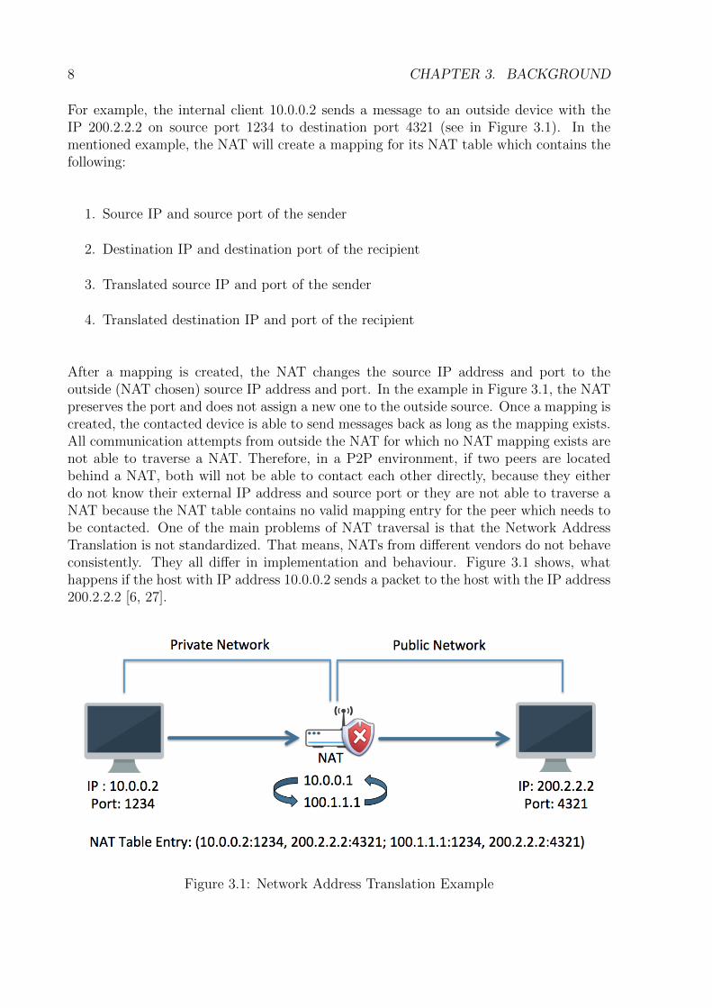
For example, the internal client 10.0.0.2 sends a message to an outside device with theIP 200.2.2.2 on source port 1234 to destination port 4321 (see in Figure 3.1). In thementioned example, the NAT will create a mapping for its NAT table which contains thefollowing:
1. Source IP and source port of the sender
2. Destination IP and destination port of the recipient
3. Translated source IP and port of the sender
4. Translated destination IP and port of the recipient
After a mapping is created, the NAT changes the source IP address and port to theoutside (NAT chosen) source IP address and port. In the example in Figure 3.1, the NATpreserves the port and does not assign a new one to the outside source. Once a mapping iscreated, the contacted device is able to send messages back as long as the mapping exists.All communication attempts from outside the NAT for which no NAT mapping exists arenot able to traverse a NAT. Therefore, in a P2P environment, if two peers are locatedbehind a NAT, both will not be able to contact each other directly, because they eitherdo not know their external IP address and source port or they are not able to traverse aNAT because the NAT table contains no valid mapping entry for the peer which needs tobe contacted. One of the main problems of NAT traversal is that the Network AddressTranslation is not standardized. That means, NATs from different vendors do not behaveconsistently. They all differ in implementation and behaviour. Figure 3.1 shows, whathappens if the host with IP address 10.0.0.2 sends a packet to the host with the IP address200.2.2.2 [6, 27].
Figure 3.1: Network Address Translation Example

3.3. TYPES OF NAT 9
3.3 Types of NAT
In order to differ between the NAT implementations, the following types are described.Full Cone NAT, Address Restricted Cone NAT, Port Restricted Cone NAT, SymmetricNAT.
3.3.1 Full Cone NAT
A Full Cone NAT works like a one-to-one mapping of IP addresses. An internal IP andport are mapped to the same external address and port. Afterwards, any external sourcecan access the internal host by sending packets to the external addresses. That means,once a mapping is created, any outside host is able to contact the internal host. Thefollowing Figure 3.2 shows a Full Cone NAT [27].
Figure 3.2: Full Cone NAT [29]
3.3.2 Address Restricted Cone NAT
The Restricted Cone NAT will assign an external address (IP) to the corresponding inter-nal host only if the internal host first contacts the external host. The external host is thenable to contact the internal host through the assigned external address. The followingFigure 3.3 shows a Restricted Cone NAT [27].
Figure 3.3: Address Restricted Cone NAT [29]
10 CHAPTER 3. BACKGROUND
3.3.3 Port Restricted Cone NAT
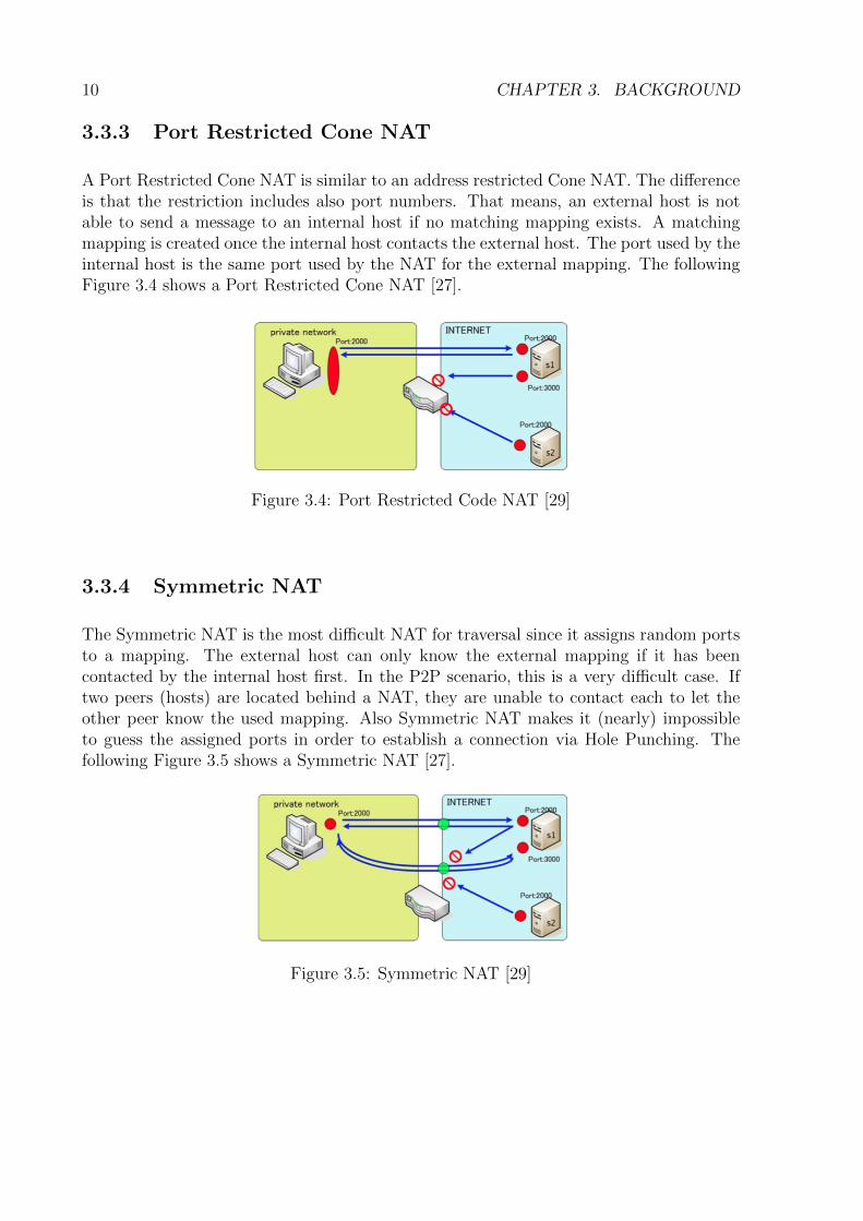
A Port Restricted Cone NAT is similar to an address restricted Cone NAT. The differenceis that the restriction includes also port numbers. That means, an external host is notable to send a message to an internal host if no matching mapping exists. A matchingmapping is created once the internal host contacts the external host. The port used by theinternal host is the same port used by the NAT for the external mapping. The followingFigure 3.4 shows a Port Restricted Cone NAT [27].
Figure 3.4: Port Restricted Code NAT [29]
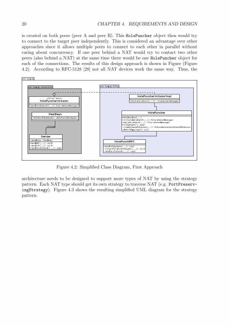
3.3.4 Symmetric NAT
The Symmetric NAT is the most difficult NAT for traversal since it assigns random portsto a mapping. The external host can only know the external mapping if it has beencontacted by the internal host first. In the P2P scenario, this is a very difficult case. Iftwo peers (hosts) are located behind a NAT, they are unable to contact each to let theother peer know the used mapping. Also Symmetric NAT makes it (nearly) impossibleto guess the assigned ports in order to establish a connection via Hole Punching. Thefollowing Figure 3.5 shows a Symmetric NAT [27].
Figure 3.5: Symmetric NAT [29]

3.4. REVERSE CONNECTION 11
3.4 Reverse Connection
A reverse connection is a mechanism, which allows a peer using no firewall or NAT de-vice to connect to another peer which is using a firewall (or NAT device without UPnP,NAT-PmP or similar mechanisms) using a relay (or a server) to establish a direct com-munication. The mechanism works as follows. Let A and B be network devices. A is notusing any kind of firewall while B uses a firewall. Assumed is also a server (or a relay) Swhich is connected to B. A first sends a connection setup request to S. S forwards thenthis message to B using its already established connection. Once B is contacted by S itstarts to connect to A and after both, A and B are connected, A is able to communicatewith B although B is using a firewall (or NAT device). The advantage of a reverse con-nection setup is that two networking devices are able to communicate even if one is usinga firewall (or a NAT device). But this mechanism has various restrictions. First, onlyone of the two devices is allowed to use a firewall (or NAT device). Second, the devicebehind a firewall (or NAT device) must have a connection to an external host like a relayor a server. Third, the device which does not use any firewall (or NAT device) needs toknow the address of the device behind the firewall and needs to be able to connect tothat host which is already connected to the device behind the firewall (or NAT device).Reverse connection is a useful mechanism only if all the previous mentioned restrictionsapply. But since many home networks are using a NAT and a firewall today, this is notconsidered a reliable option for connecting two peers of a P2P network which are locatedbehind a NAT device or a firewall. Figure 3.6 shows the NAT traversal by connectionreversal process [28].
Figure 3.6: NAT Traversal by Connection Reversal [28]

12 CHAPTER 3. BACKGROUND
3.5 Universal Plug and Play
In many home network systems of today, there is a need for P2P applications (e.g.Skype [7]). However, in many cases in which both endpoints are using a NAT devices,the connection cannot be established. A possible solution to this problem is the use ofUniversal Plug and Play (UPnP). UPnP is a definition of an architecture in order to gainP2P network connectivity. It defines a set of common protocols and procedures to guaran-tee interoperability of network-enabled computers, appliances, and wireless devices. TheUPnP Forum claims the UPnP technology provides an open and distributed networkingarchitecture which influences TCP/IP and the Web technologies in a positive way. Inshort terms this technology works as follows:
1. Addressing: Every device obtains an IP address.
2. Discovery: UPnP control point(s) are informed by- or inform all devices aboutits/their existence.
3. Description: The UPnP control point learns about the device capabilities.
4. Control: A control point sends commands to device(s).
5. Eventing: A control point listens to state changes in device(s).
6. Presentation: A control point displays a user interface for device(s) (e.g. a webpage).
An advantage of a P2P system, which uses UPnP, is that it is able to communicate withoutbeing blocked by any kind of NAT or firewall. Further, UPnP configures itself withoutthe user noticing and supports various operating systems. However, on the other hand,this technology may not be enabled on routers and servers and therefore the availabilitydepends on the vendors. Although there is a definition of the UPnP architecture, manydifferent implementations of UPnP exist. In the past, several UPnP implementations hadsecurity flaws, since it offers no authentication mechanism (e.g. Microsoft UPnP [22, 10]).A further disadvantage of UPnP is, that it does not support multiple layers of NAT [11, 12].
3.6 NAT Port mapping Protocol
The NAT Port mapping Protocol (NAT-PmP) is a NAT traversal mechanic developedby Apple Inc. in 2005. This protocol is an extension for a NAT device which automatesthe port forwarding procedure for a NAT user. NAT-PmP offers several interfaces to apossible user like:
• Public address request
• New port mapping
• Destruction of a port mapping

3.7. HOLE PUNCHING 13
Unlike UPnP, this protocol offers an authentication mechanism which is considered as andadvantage. Another advantage of NAT-PmP is that outside devices can request a newconnection to an inside device (behind the NAT). This procedure works similar to UPnPsince it uses a standard port. A disadvantage of NAT-PmP is that it lacks support forconnections through multiple layers of NAT. So, if a user of NAT-PmP uses two or moreNATs, a user outside the NAT is may not able to connect to that user. Also NAT-PmP isnot integrated in many non-Apple devices. For example, less than half of the tested routers(see in in Appendix C) implemented NAT-PmP while all of them supported UPnP [9].
3.7 Hole Punching
Hole Punching is a mechanism, which allows two network devices behind a NAT to contacteach other by letting the other device know their private and public endpoint information.Therefore, it belongs to the knowledge based NAT traversal mechanisms. The require-ment is to have a third party network device which is publicly available from both networkdevices and acting as a port and setup information exchange server. The Hole Punchingprocedure works as follows.
In this scenario two network devices (Host A and Host B) behind a NAT device areassumed. Both have private IP addresses. A third device (Server S), which does notuse any kind of NAT is assumed as well. This Server S has to be publicly availableand addressable from host A and B. Suppose host A wants to establish a direct UDPcommunication session with host B. If A just start sending messages to B’s NAT (B’spublic endpoint), the NAT of host B will ignore all messages of A, because there is noappropriate mapping entry in the mapping table of Host B [28].
1. Host A starts sending UDP messages to host B
2. At the same time, host A contacts host B via server S (relaying) and communicatesits public and private endpoint information (on which port it is going to contacthost B)
3. Once contacted by host A, host B will start sending UDP messages to host A publicendpoint
4. At the same time host B contacts host A via server S (relaying) and communicatesits public and private endpoint information (on which port it is going to contacthost A)
5. Once the port information is exchanged, both hosts (A and B) are now able toestablish a new communication session directly (with no further help of server S)
This procedure is also shown Figure 3.7 and Figure 3.8.

14 CHAPTER 3. BACKGROUND
(a) Before Hole Punching (b) The Hole Punching Process
Figure 3.7: UDP Hole Punching Process [28]
Figure 3.8: After Hole Punching [28]

3.8. SUMMARY 15
3.8 Summary
While there already exist several methods to traverse a NAT, none of the above mentioned,except for Hole Punching, works if two network devices behind a NAT want to connect toeach other and at least one of them does not support NATPmP and UPnP or is locatedbehind multiple layers of NAT. Thus it is essential for TomP2P to support Hole Punching,which allows the connection of two devices behind a NAT to be able to connect to eachother directly. Additionally, with Hole Punching no special software is required for theNAT device used by a peer. Further if a P2P network like TomP2P wants to introducedirect communication between two or more peers behind a NAT device, Hole Punching isan appropriate mechanism.

16 CHAPTER 3. BACKGROUND

Chapter 4
Requirements and Design
This chapter covers the requirements and design process of this thesis.
4.1 Requirements
The goal of this bachelor thesis is to enable NAT traversal with the use of UDP HolePunching. To achieve this goal, a number of user stories were created and classified inthree possible groups which were Must-Haves, Should-Haves, Nice-to-Haves. A detailedenumeration of the user stories is listed below.
1. Must-Have
1.1. A peer behind a NAT must be able to connect to another client behind a NATusing a specific RPC (Remote Procedure Call) to connect in order to be ableto communicate with that other peer.
1.2. The P2P system must be able to detect if a hole punch is possible or not inorder to know if it should use Hole Punching.
1.3. The peer must use relaying as a fallback scenario if Hole Punching does notwork because it should still be able to communicate with other peers behindNATs.
2. Should-Have
2.1. A client using Hole Punching should be able to use different Hole Punching sce-narios (fallback) in order to punch holes and establish a connection to anotherpeer behind a NAT.
3. Nice-to-Have
3.1. A peer behind a NAT should be able to communicate with other peers behindNATs via Hole Punching while using a NAT machine from one of the wellknown router vendors (ASUS, Zyxel, Cisco, DLink, AVM, etc...).
17

18 CHAPTER 4. REQUIREMENTS AND DESIGN
3.2. The peer should be able to support UDP based data Transfer (UDT) [16] orsome related protocol to enable a better way of communication.
4.2 Design
The design of this bachelor thesis had different phases. First of all, a proof of Concepthas been made. With the obtained knowledge from the proof-of-concept, a first testapplication was implemented in order to simulate a P2P network with NAT functionality.
4.2.1 Proof-of-Concept
A proof-of-concept demonstrates the feasibility of a particular idea or methodology tocomplete a particular task. In order to demonstrate the possibility of a working HolePunching feature for TomP2P, tests with the program sendip [30] were made. The goal ofthis proof-of-concept was to punch holes into both of the in Subsection 5.1.2 mentionedIptables firewalls. First, both of the machines behind a firewall were triggered to sendUDP messages to a before specified port to the other NAT. While sending those UDPpackages, the whole network traffic has been monitored with wireshark and conntrack todetermine whether the Hole Punching succeeded or not.
Not only the proof-of-concept was successful, but also the NAT behaviour of Iptablesfirewall could be determined. After the tests with sends it became clear, that Iptableswould create a NAT table entry for every new connection that is opened. In the firstplace, Iptables would assign, if not already used, the same source port a client used toestablish a connection to another user in a different network. But if that source portwould be already in use, it would just change that source port on NAT level to a portnumber starting at 1024 and incrementing.
4.2.2 Design of the Hole Punching Feature
It is assumed that there exists two peers (peer A and peer B) which are located behinddifferent NATs. At least one of them (in this case peer B) is connected to a third peer(peer C, a relay) via a TCP connection. The design of the solution was inspired fromthe Must-Have requirements (see in Section 4.1). The idea was, that a peer A (behind aNAT) wants to transmit a single message to peer B via a direct communication channelwhile using UDP.
Mechanism Design
The Hole Punching mechanism for TomP2P was designed according to the Hole Punchingmechanism mentioned in Section 3.7. The first step (1. checkIfHolePunchingPossi-
ble()) for peer (unreachable peer A) is to check its reachability from the outside network.

4.2. DESIGN 19
If and only if both, unreachable peer A and unreachable peer B, are behind a NAT peer.Peer A starts initiating the Hole Punching process (2. initiateHolePunch()). Thepeer then creates a message with its private endpoint information (source ports and pri-vate IP address) and transmits this message to a relay peer of unreachable peer B (3.communicatePrivateEndpoint()). The relay peer recognizes the incoming request fromunreachable peer A and forwards it to unreachable peer B (4. forwardMessage()).Once the message with the private endpoint information has reached unreachable peer B,it recognizes the incoming Hole Punch request. It then creates also a message with itsprivate endpoint information (5. replyHolePunch()). At the same time unreachablepeer B starts sending dummy (e.g. empty) messages to the unreachable peer A commu-nicated private endpoints (6. sendDummyMessage). After the creation of the messagecontaining its own private endpoint, unreachable peer B replies to the relay peer (7.communicatePrivateEndpoint()). The relay peer then forwards this message back tounreachable peer A (8. forwardMessage()). Once the message containing the privateendpoint information has reached unreachable peer A, it starts sending the original mes-sage through the from unreachable peer B created NAT holes (9. sendOriginalMes-
sage()). The following Figure (Figure 4.1) shows the above explained mechanism in asequence diagram.
Figure 4.1: Sequence Diagram Hole Punching
Class Diagram
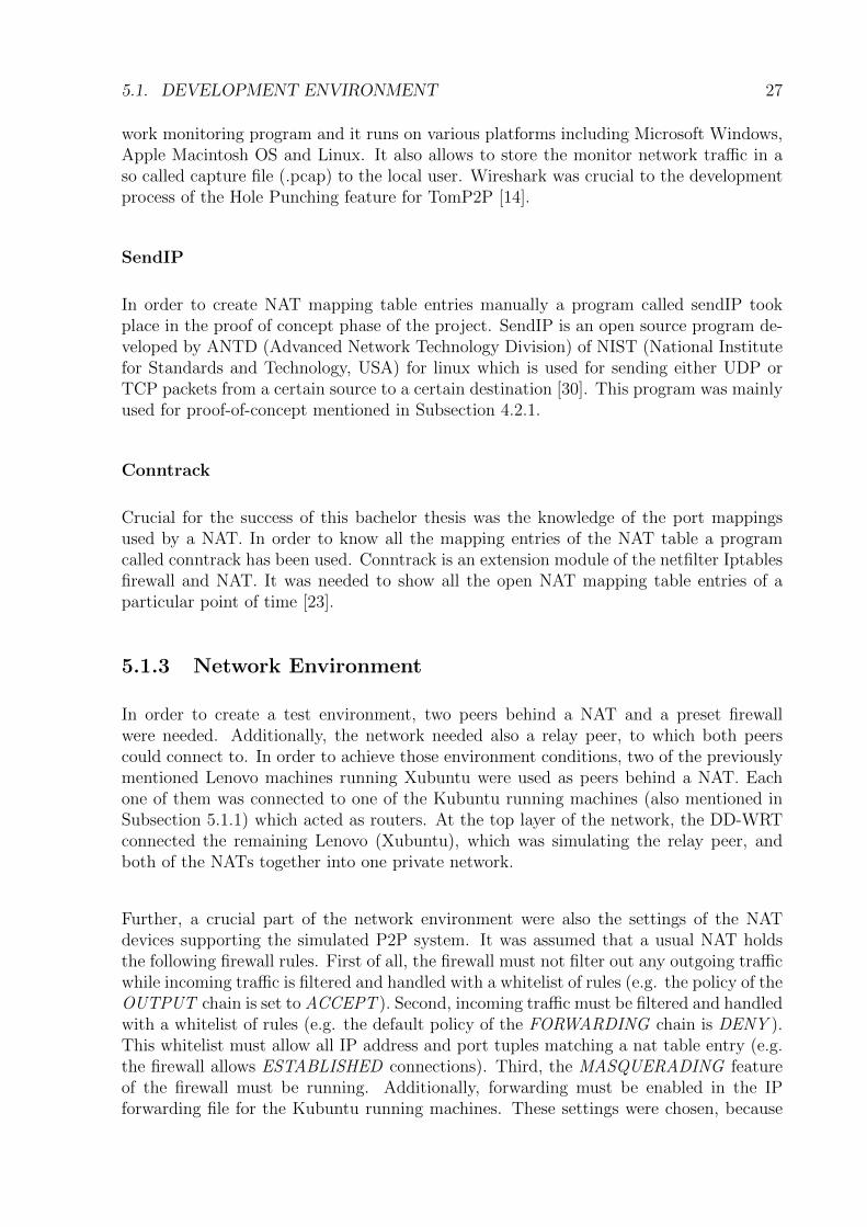
According to the mechanism, which has been defined previously, the class diagram shownin Figure 4.2 was designed. The idea is to create a generic HolePuncher object, which
20 CHAPTER 4. REQUIREMENTS AND DESIGN
is created on both peers (peer A and peer B). This HolePuncher object then would tryto connect to the target peer independently. This is considered an advantage over otherapproaches since it allows multiple peers to connect to each other in parallel withoutcaring about concurrency. If one peer behind a NAT would try to contact two otherpeers (also behind a NAT) at the same time there would be one HolePuncher object foreach of the connections. The results of this design approach is shown in Figure (Figure4.2). According to RFC-5128 [28] not all NAT devices work the same way. Thus, the
Figure 4.2: Simplified Class Diagram, First Approach
architecture needs to be designed to support more types of NAT by using the strategypattern. Each NAT type should get its own strategy to traverse NAT (e.g. PortPreserv-ingStrategy). Figure 4.3 shows the resulting simplified UML diagram for the strategypattern.

4.2. DESIGN 21
Figure 4.3: Simplified Class Diagram, Final Design

22 CHAPTER 4. REQUIREMENTS AND DESIGN

Chapter 5
Implementation
In the following sections, the development environment, the main code changes and newcreated classes in the TomP2P framework will be explained.
5.1 Development Environment
In this Section, the software and hardware components used in this thesis are covered.Subsection 5.1.1 Hardware Environment describes the hardware used in the design, de-velopment and testing process. Subsection 5.1.2 Software Environment describes all thesoftware components used in this thesis. Subsection 5.1.3 shows how the soft- and hard-ware environment were integrated to one development environment.
5.1.1 Hardware Environment
Only Notebooks or Desktop PC’s were used to develop the required Hole Punching feature.To simulate the peers behind a NAT and the relay peer, three Lenovo T61 ThinkPadswere used. Each of those notebooks ran the Xubuntu (Ubuntu 14.04) OS. Each one ofthe machines for the peers had a Intel Core 2 Duo CPU T7500 at 2.20 GHz and 2 GBof RAM. Additionally, a MacBook Pro (Early 2011) with 16GB RAM and a 2Ghz IntelCore i7 (2nd Generation) was used for development. In order to simulate two peers behindone NAT, also a Lenovo ThinkPad T410, which ran Ubuntu 14.04 OS while using a IntelCore i7 (3rd Generation) at 2.67 GHz and 8 GB RAM, was used in the developmentprocess. All these machines were connected to each other via switches and routers whichare explained more detailed in Subsection 5.1.3. Figure 5.1 shows the environment, whichwas used to implement and test the Hole Punching feature.
Router Environment
To implement Hole Punching into the Appendix framework, routers were needed to con-nect the peers to each other in order to simulate a P2P network with NAT boundaries.
23

24 CHAPTER 5. IMPLEMENTATION
Figure 5.1: The Development Environment
The decision was to use two Desktop PC’s running on Kubuntu (Ubuntu 14.04). Each oneof the machines had an Intel Pentium 4 with 2.80 GHz, 512 MB of RAM and two networkcards. Those PC’s were used, because many router operating systems are created by itsvendors and therefore not freely available. Also the remaining freely available operatingsystems were hard to debug (e.g. run commands like conntrack to show the current NATmapping table entries [23]). Therefore it has been decided to use the Linux operatingsystem as a router. A crucial advantage of using those machines were the tools which arefreely available on Linux. If a simple router would have been used, there would not havebeen the possibility to install programs like wireshark or ipsend. Further, a requirementfor this bachelor thesis was that the Hole Punching feature should work with the LinuxIptables firewall and NAT. Additionally, a router from ASUS [17] was used to simulate theinternet. In detail, the ASUS W-500g Deluxe running the DD-WRT operating system [15]with version DD-WRT v24-sp2 took place and supported the network with WAN accessas well as with a DHCP Server for the above mentioned Linux machines.
5.1.2 Software Environment
TomP2P is a P2P distributed hash table (DHT) framework developed by Thomas Bocekand written in Java 1.6 [4]. One of the goals of this bachelor thesis is to implement HolePunching into TomP2P [8].

5.1. DEVELOPMENT ENVIRONMENT 25
Eclipse
Eclipse is an Integrated Development Environment (IDE) for various programming lan-guages like Java, C++ or PHP. Needed for this bachelor thesis was an IDE which wascapable of supporting Java 1.6 since the TomP2P framework uses this programming lan-guage. Since Eclipse supports all Java versions, this IDE was used. Additionally, Eclipsesupports a lot of extensions which are freely available on the Eclipse Marketplace. Indetail, Maven Integration for Eclipse (m2e) 1.5, EclEmma Java Code Coverage 2.3.2, theintegrated JUnit 4.0 test framework and the integrated Git tool were heavily used for thedevelopment [13, 4].
Git and Github
For the development process, a version control system was needed. The decision wasto use Git, because it is a free and open source version control system. It is also welldocumented and it claims to be fast. But the main reason for using Git was the fact, thatthe TomP2P source code was hosted on Github. Github is a company which allows opensource developers to freely host their code on their servers. Github provides repositoriesfor git projects which was needed for the development of the Hole Punching feature withgit. Another advantage of using Github was the import repository function which allowedto make a copy of an existing repository. With this function, a clone of the original sourcecode could easily be made and used for development [3, 2].
Iptables
Iptables is a command line based ip packet filter firewall with integrated NAT functionali-ties for Linux. Iptables allows extensive control and debugging possibilities to a developerwhich needs to develop a Hole Punching feature.
An Iptables firewall consists of chains, tables and policies. In the standard case, there arefive such chains which an ip packet could pass. The names for the chains are PREROUT-ING, INPUT, OUTPUT, FORWARD, POSTROUTING. Additionally, chains could alsobe added by the user, but for this work, only the standard ones were needed. Fur-thermore, each of the chains obtains a policy. A policy determines the default be-havior of each chains while handling a packet which does not meet any rule of its ta-bles. There are three available policies in the standard Iptables build. First, there isthe ACCEPT policy, second the DENY policy and third, the REJECT policy. If achain obtained the ACCEPT policy, it will allow all packets while the DENY policywill ignore all packets. In the DENY case the sender or recipient of the packet willnot get any notification about the packet. If such a notification is needed the useris able to set the chain policy to REJECT. There are also tables, which are used inIptables to either explicitly allow or deny (this depends on the default policy) packethandling in a chain. Although not all possible tables are used in a chain defaultly,the user has the possibility to create new or add already existing tables to a chain.The standard chains are called RAW, MANGLE, FILTER and NAT. While the RAW

26 CHAPTER 5. IMPLEMENTATION
Figure 5.2: Iptables Packet Processing [1]
table is only used to mark if a connec-tion should be tracked or not, MAN-GLE is used to manipulate the headerof a packet (e.g. change the typeof service). But the most impor-tant tables for this thesis were the ta-bles called FILTER and NAT. The fil-ter table is responsible of filtering thelayer three and four packets accord-ing to their source and destination IPand port. So this is where the fire-walls sorts out all the packets whichare allowed or not allowed dependingon the chain policy. In the NAT ta-ble, Iptables handles the whole net-work address translation table. Alsothe port address translation table is han-dled in the NAT table. Both, NATand Port Address Translation (PAT) arevery important for this bachelor the-sis since Hole Punching mechanism de-pends strongly on the behaviour of thosetwo tables (NAT table and PAT ta-ble) [23].
While processing the Iptables packet filter,there can be three different ways for an IPpacket. It is assumed that all machines
mentioned run a current and up to date version of Iptables. In the most importantcase for Hole Punching, in the case of forwarding, the packet will first be passed to thePREROUTING chain. The PREROUTING holds a NAT table, which is responsiblefor the destination NAT. That means if there exists a mapping for a given IP addressand port, the destination of the packet will be changed by this table. If there exists avalid mapping in the PAT table, the packet will be handed, after the routing decision,to the FORWARDING chain. If the packet then passes this chain it will go to thePOSTROUTING chain. Once the packet reaches this chain, the source address and portwill be changed to the address and port of the recipient and afterwords sent to it. Thewhole process flow of the Iptables firewall can also be seen in Figure 5.2 [23].
Wireshark
For the whole testing process and the process of the proof of concept, a network moni-toring program was needed. The requirement was a program which monitors all packetson layer three and four with their source IP, source port, destination IP, destination port,protocol and content. wireshark fulfilled the requirements mentioned above. It is a net-
5.1. DEVELOPMENT ENVIRONMENT 27
work monitoring program and it runs on various platforms including Microsoft Windows,Apple Macintosh OS and Linux. It also allows to store the monitor network traffic in aso called capture file (.pcap) to the local user. Wireshark was crucial to the developmentprocess of the Hole Punching feature for TomP2P [14].
SendIP
In order to create NAT mapping table entries manually a program called sendIP tookplace in the proof of concept phase of the project. SendIP is an open source program de-veloped by ANTD (Advanced Network Technology Division) of NIST (National Institutefor Standards and Technology, USA) for linux which is used for sending either UDP orTCP packets from a certain source to a certain destination [30]. This program was mainlyused for proof-of-concept mentioned in Subsection 4.2.1.
Conntrack
Crucial for the success of this bachelor thesis was the knowledge of the port mappingsused by a NAT. In order to know all the mapping entries of the NAT table a programcalled conntrack has been used. Conntrack is an extension module of the netfilter Iptablesfirewall and NAT. It was needed to show all the open NAT mapping table entries of aparticular point of time [23].
5.1.3 Network Environment
In order to create a test environment, two peers behind a NAT and a preset firewallwere needed. Additionally, the network needed also a relay peer, to which both peerscould connect to. In order to achieve those environment conditions, two of the previouslymentioned Lenovo machines running Xubuntu were used as peers behind a NAT. Eachone of them was connected to one of the Kubuntu running machines (also mentioned inSubsection 5.1.1) which acted as routers. At the top layer of the network, the DD-WRTconnected the remaining Lenovo (Xubuntu), which was simulating the relay peer, andboth of the NATs together into one private network.
Further, a crucial part of the network environment were also the settings of the NATdevices supporting the simulated P2P system. It was assumed that a usual NAT holdsthe following firewall rules. First of all, the firewall must not filter out any outgoing trafficwhile incoming traffic is filtered and handled with a whitelist of rules (e.g. the policy of theOUTPUT chain is set to ACCEPT ). Second, incoming traffic must be filtered and handledwith a whitelist of rules (e.g. the default policy of the FORWARDING chain is DENY ).This whitelist must allow all IP address and port tuples matching a nat table entry (e.g.the firewall allows ESTABLISHED connections). Third, the MASQUERADING featureof the firewall must be running. Additionally, forwarding must be enabled in the IPforwarding file for the Kubuntu running machines. These settings were chosen, because

28 CHAPTER 5. IMPLEMENTATION
it was assumed, that a usual NAT device holds similar settings. A more detailed view ofthe whole network setup is described in Figure 5.3. The detailed configuration files forthe Iptables routers can be looked up in the Appendix B.
Figure 5.3: Network Plan Overview

5.2. NEW CLASSES AND CODE CHANGES 29
5.2 New Classes and Code Changes
The following subsections describe all new classes and code changes, which were made toimplement Hole Punching into TomP2P.
5.2.1 PeerNAT
Since Hole Punching is an mechanism for NAT traversal, the package tomp2p-nat wasused. Similar to the initialization of the reverse connection or the relaying feature ofTomP2P, the initialization of the Hole Punching feature has been placed also into thePeerNAT and its builder class. Whenever a user now creates a PeerNAT object, it willbe able to contact other peers via Hole Punching. In the PeerBuilderNAT, the user isable to change the number of holes punched by the HolePuncher object explained inSubsection 5.2.5. Additionally, the user can also set the number of punches, which areused by the target peer to force its NAT device to create NAT mappings.
5.2.2 Sender
The Sender class in TomP2P is the central instance for coordinating the send mechanismin order to contact other peers. It takes care about all the outgoing connections which areeither TCP or UDP nature. Because Hole Punching in TomP2P should only be availablevia UDP, small changes inside the sendUDP() method were made. In case a messagecontains SendBehaviour.HOLEP, the new created method handleHolePunch() is called.This method is responsible for initiating the Hole Punch procedure in TomP2P as well asif the procedure fails, sending it via relaying (fallback scenario).
5.2.3 HolePInitiator and HolePunchInitiatorImpl
The HolePInitiator (HoleP is the short form of Hole Puncher in TomP2P) is the interfacefrom the tomp2p-core package to the tomp2p-nat package. It provides only one method,handleHolePunch(), which returns a FutureDone<Message>. The detailed code of theinterface HolePInitiator is listed in the Listing 5.1.
Listing 5.1: HolePInitiator Interface
public interface HolePInitiator {
public FutureDone<Message> handleHolePunch(final int idleUDPSeconds, final
FutureResponse futureResponse, final Message originalMessage);
}
The HolePInitiatorImpl class is the implementation of the HolePInitiator interfaceand is meant to be instanciated by the PeerBuilderNAT class. It also takes care about

30 CHAPTER 5. IMPLEMENTATION
the NAT type which a peer has to deal with. Based on the detected NAT type it will alsodecide weather a hole punch is possible or not.
5.2.4 HolePStrategy
The HolePStrategy class is the interface for all HoleP objects. It provides three interfacemethods which are needed for each hole punch set up. Two of them are needed also forthe implemented strategy pattern. The detailed code of the mentioned interface can belooked up in the Listing 5.2
Listing 5.2: HolePStrategy Interface
public interface HolePStrategy {
// these values will never change
public static final boolean BROADCAST_VALUE = false;
public static final boolean FIRE_AND_FORGET_VALUE = false;
public FutureDone<Message> initiateHolePunch(final FutureDone<Message>
mainFutureDone, final FutureResponse originalFutureResponse);
public FutureDone<Message> replyHolePunch();
public void tryConnect() throws Exception;
}
5.2.5 AbstractHolePStrategy
One of the most important classes is the AbstractHolePStrategy class. This class imple-ments the HolePStrategy interface and provides all methods needed for the Hole Punchmechanism except for the port guessing. Each time a peer behind a NAT device wants tosend a message to another peer behind a NAT device, a subclass of AbstractHolePStrat-egy is instantiated on both peers. The implementation of the Hole Punching mechanismmentioned in Subsection 4.2.2 is explained in detail in the following sentences.
First, the AbstractHolePStrategy is never instantiated directly, only its subclasses suchas NonPreservingSequentialStrategy or PortPreservingStrategy will call its con-structor. The constructor itself initializes all global variables which are needed for theHole Punching procedure. Once an object of this class is instantiated the initiate-
HolePunch() method is ready to be called. This method is responsible for the HolePunch mechanism on the initiating peer side and will execute the following steps:
1. It will create a FutureDone<Message> which is returned to the Sender class in orderto determine whether or not the Hole Punching procedure was successful.

5.2. NEW CLASSES AND CODE CHANGES 31
2. The createChannelFutures() method is called to create the needed ChannelFu-
tures. This method will call also the prepareHandlers() method in order toprovide the handling mechanism if the hole punch setup attempt was successful.
3. The createInitMessage() method is called, which will create the setup messagewhich is sent to the other peer via the HolePRPC class. The method will also call thesubclass implementation of the doPortGuessingInitiatingPeer() method whichis responsible for the port guessing. The message then stores the necessary portinformation in a Buffer.
4. The sendHolePInitMessage() is called. This method will create a new Channel-
Creator and will send the above mentioned setup message to a randomly chosenrelay peer of the peer which is needed to be contacted.
The following Listing 5.3 shows the initiateHolePunch method in detail.
Listing 5.3: The initiateHolePunch() Method
public FutureDone<Message> initiateHolePunch(final FutureDone<Message>
mainFutureDone, final FutureResponse originalFutureResponse) {
//check if testCase == true
if (((HolePInitiatorImpl)
peer.peerBean().holePunchInitiator()).isTestCase()) {
mainFutureDone.failed("Gandalf says: You shall not pass!!!");
return mainFutureDone;
}
final FutureDone<List<ChannelFuture>> fDoneChannelFutures =
createChannelFutures(prepareHandlers(true, mainFutureDone),
mainFutureDone, numberOfHoles);
fDoneChannelFutures.addListener(new
BaseFutureAdapter<FutureDone<List<ChannelFuture>>>() {
@Override
public void operationComplete(final FutureDone<List<ChannelFuture>>
future) throws Exception {
if (future.isSuccess()) {
final List<ChannelFuture> futures = future.object();
final FutureDone<Message> initMessage =
createInitMessage(futures);
initMessage.addListener(new
BaseFutureAdapter<FutureDone<Message>>() {
@Override
public void operationComplete(final FutureDone<Message>
future) throws Exception {
if (future.isSuccess()) {
final Message initMessage = future.object();
sendHolePInitMessage(mainFutureDone,
originalFutureResponse, futures, initMessage);
} else {
mainFutureDone.failed("The creation of the initMessage
failed!");
32 CHAPTER 5. IMPLEMENTATION
}
}
});
} else {
mainFutureDone.failed("No ChannelFuture could be created!");
}
}
});
return mainFutureDone;
}
The AbstractHolePStrategy object is also used by the replying peer side. The replyingpeer will always call the replyHolePunch() method. This method works similar to theinitiateHolePunch() method. There are three differences between the previously men-tioned methods. First, replyHolePunch() will call the subclass method of doPortGuess-ingTargetPeer() instead of doPortGuessingInitiatingPeer(). Second, it executes aport mapping between the ports of the initiating peer and the ports of itself and store itto the Buffer of the setup message. Third, it will create a HolePScheduler object, whichwill call tryConnect() in order to punch the needed holes into the NAT. The methodtryConnect() is responsible for sending so called dummy messages to the initiating peer.The sending of these messages will then cause the NAT to create the correct mappingentries so that the initiating peer is able to connect. After the sending of the dummymessages the replying peer will reply the setup message (including the port mappings) tothe initiating peer.
Once the relplying peers message reached the initiating peer again, the initiating peerwill start to send the original message to its destination peer (which is the replying peer).If the sending of the original message fails, it will use its relay fallback scenario. Thefollowing Listing 5.4 shows the replyHolePunch() method in detail.
Listing 5.4: The replyHolePunch() Method
public FutureDone<Message> replyHolePunch() {
originalSender = (PeerAddress)
originalMessage.neighborsSetList().get(0).neighbors().toArray()[0];
final FutureDone<Message> replyMessageFuture = new FutureDone<Message>();
final HolePStrategy thisInstance = this;
final FutureDone<List<ChannelFuture>> rmfChannelFutures =
createChannelFutures(prepareHandlers(false, replyMessageFuture),
replyMessageFuture, numberOfHoles);
rmfChannelFutures.addListener(new
BaseFutureAdapter<FutureDone<List<ChannelFuture>>>() {
@Override
public void operationComplete(final FutureDone<List<ChannelFuture>>
future) throws Exception {
if (future.isSuccess()) {
channelFutures = future.object();
final FutureDone<Message> replyMessageFuture2 =

5.2. NEW CLASSES AND CODE CHANGES 33
createReplyMessage();
replyMessageFuture2.addListener(new
BaseFutureAdapter<FutureDone<Message>>() {
@Override
public void operationComplete(final FutureDone<Message>
future) throws Exception {
if (future.isSuccess()) {
final Message replyMessage = future.object();
final Thread holePunchScheduler = new Thread(new
HolePScheduler(peer.peerBean().holePNumberOfPunches(),
thisInstance));
holePunchScheduler.start();
replyMessageFuture.done(replyMessage);
} else {
replyMessageFuture2.failed("No ReplyMessage could be
created!");
}
}
});
} else {
replyMessageFuture.failed("No ChannelFuture could be created!");
}
}
});
return replyMessageFuture;
}
5.2.6 Port Guessing Strategies
PortPreservingStrategy and NonPreservingSequentialStrategy are subclasses of theAbstractHolePStrategy class. These instances are very important since they implementthe abstract methods doPortGuessingInitiatingPeer() and doPortGuessingTarget-
Peer(). Both methods are responsible for the port information exchange between the ini-tiating and the replying peer. They will provide mechanisms to determine the used NATmapping entries on each side. The following Listing 5.5 shows the doPortGuessingIni-
tiatingPeer() method of the PortPreservingStrategy class.
Listing 5.5: The doPortGuessingInitiatingPeer() Method
@Override
protected void doPortGuessingInitiatingPeer(final Message holePMessage,
final FutureDone<Message> initMessageFutureDone,
final List<ChannelFuture> channelFutures) throws Exception {
final List<Integer> portList = new
ArrayList<Integer>(channelFutures.size());
for (int i = 0; i < channelFutures.size(); i++) {

34 CHAPTER 5. IMPLEMENTATION
final InetSocketAddress inetSocketAddress = (InetSocketAddress)
channelFutures.get(i).channel().localAddress();
portList.add(inetSocketAddress.getPort());
}
holePMessage.intValue(portList.size());
holePMessage.buffer(encodePortList(portList));
initMessageFutureDone.done(holePMessage);
}
5.2.7 HolePRPC
The HolePRPC class is responsible for the message exchange between the two peers whichwant to connect to each other. Its main methods are forwardHolePunchMessage() andhandleHolePunch(). forwardHolePunchMessage() is executed on a relay of the des-tination peer and is responsible for transmitting the setup message from the initiatingpeer to the replying peer and from the replying peer back to the initiating peer. Thisis done via relaying. The handleHolePunch() method is executed on the replying peeronce it receives a hole punch setup message. It will create an instance of a subclass ofAbstractHolePStrategy and will then call its replyHolePunch() method.
5.2.8 HolePScheduler
The HolePScheduler class is used as a Java thread to call the tryConnect() method of aHolePStrategy instance. tryConnect() sends each time it is called a dummy message tothe initiating peer in order to force its NAT device to create a NAT mapping table entry.The number of punches can be specified on creation of the PeerNAT object. Therefore,the HolePScheduler may call tryConnect() a predefined number of times. The followingListing 5.6 shows an example how the number of punches can be specified. If no numberis specified, the default value for the number of punches is three.
Listing 5.6: Example of Number of Punches
final int numberOfPunches = 42;
final PeerNAT peerNAT = new
PeerBuilderNAT(peer).holePNumberOfHolePunches(numberOfPunches).start();
5.2.9 DuplicatesHandler
The DuplicatesHandler class is a subclass of the SimpleChannelInboundHandler class.It makes sure that the destination peer of the initiating peer does not receive a messagemore than one times. The reason why duplicates appear is because the implementation ofthis Hole Punching feature uses more than one hole to connect two NAT peers together.Using more than one holes makes the Hole Punching more reliable to errors.
5.2. NEW CLASSES AND CODE CHANGES 35
5.2.10 NATType
NATType is an enum and a crucial part of the implemented strategy pattern. EveryNATType holds a method holePuncher(), which returns the needed HolePunchStrategy
given the NATType. In the following list, all NATTypes are mentioned and explained.
• UNKNOWN: This means, that the peer does not know whether or not it is using a NATdevice.
• NO_NAT: This means, that the peer is not using a NAT device.
• PORT_PRESERVING: This means, that the peer is using a non-symmetric NAT device.
• NON_PRESERVING_SEQUENTIAL: This means, that the peer is using a symmetric NATdevice which assigns ports in a sequential manner.
• NON_PRESERVING_OTHER: This means, that the peer is using a symmetric NAT devicewhich assigns ports randomly.
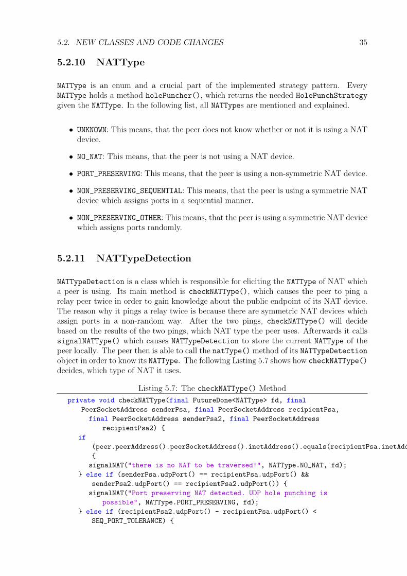
5.2.11 NATTypeDetection
NATTypeDetection is a class which is responsible for eliciting the NATType of NAT whicha peer is using. Its main method is checkNATType(), which causes the peer to ping arelay peer twice in order to gain knowledge about the public endpoint of its NAT device.The reason why it pings a relay twice is because there are symmetric NAT devices whichassign ports in a non-random way. After the two pings, checkNATType() will decidebased on the results of the two pings, which NAT type the peer uses. Afterwards it callssignalNATType() which causes NATTypeDetection to store the current NATType of thepeer locally. The peer then is able to call the natType() method of its NATTypeDetectionobject in order to know its NATType. The following Listing 5.7 shows how checkNATType()
decides, which type of NAT it uses.
Listing 5.7: The checkNATType() Method
private void checkNATType(final FutureDone<NATType> fd, final
PeerSocketAddress senderPsa, final PeerSocketAddress recipientPsa,
final PeerSocketAddress senderPsa2, final PeerSocketAddress
recipientPsa2) {
if
(peer.peerAddress().peerSocketAddress().inetAddress().equals(recipientPsa.inetAddress()))
{
signalNAT("there is no NAT to be traversed!", NATType.NO_NAT, fd);
} else if (senderPsa.udpPort() == recipientPsa.udpPort() &&
senderPsa2.udpPort() == recipientPsa2.udpPort()) {
signalNAT("Port preserving NAT detected. UDP hole punching is
possible", NATType.PORT_PRESERVING, fd);
} else if (recipientPsa2.udpPort() - recipientPsa.udpPort() <
SEQ_PORT_TOLERANCE) {

36 CHAPTER 5. IMPLEMENTATION
signalNAT("NAT with sequential port multiplexing detected. UDP hole
punching is still possible",
NATType.NON_PRESERVING_SEQUENTIAL, fd);
} else {
signalNAT("Symmetric NAT detected (assumed since all other tests
failed)", NATType.NON_PRESERVING_OTHER, fd);
}
}
Chapter 6
Evaluation
The following sections cover the automated and manual testing (Sections 6.1 and 6.2),the router test and its results (see in Subsections 6.2.1 and 6.2.2), a comparison of HolePunching to Flooding (see in Section 6.3, and the Limitations of this thesis (see in Sec-tion 6.4).
6.1 Unit Testing
All created unit tests for this thesis can be found in the /src/test/java/net/tomp2p/ho-lep/strategy folder in the tomp2p-nat package. For overall testing a test which proveswhether or not the Hole Punching procedure works without throwing an error or trans-mitting the wrong data was implemented. Such a test was implemented inside the Ab-
stractTestHolePuncher class and the IntegrationTestHolePuncher class. Also sev-eral smaller unit test were written to ensure that the code works as specified. Those testswere implemented in the TestHolePunchScheduler class, TestNATType class, HoleP-
StressTest and the IntegrationTestBootstrapBuilder class.
6.2 Manual Testing
For the real world tests, the previously mentioned environment (see in Chapter 5.1 on page23) was used. This environment was used, because of the complexity of possible errorslike wrong mapping entries, runtime errors or even deadlocks. The use of integrationtesting was a key to the success of the implementation of Hole Punching into the TomP2Pframework, because it gave immediate feedback if some part of the code was not runningor running with errors. It also prevented many consecutive errors.
37
38 CHAPTER 6. EVALUATION
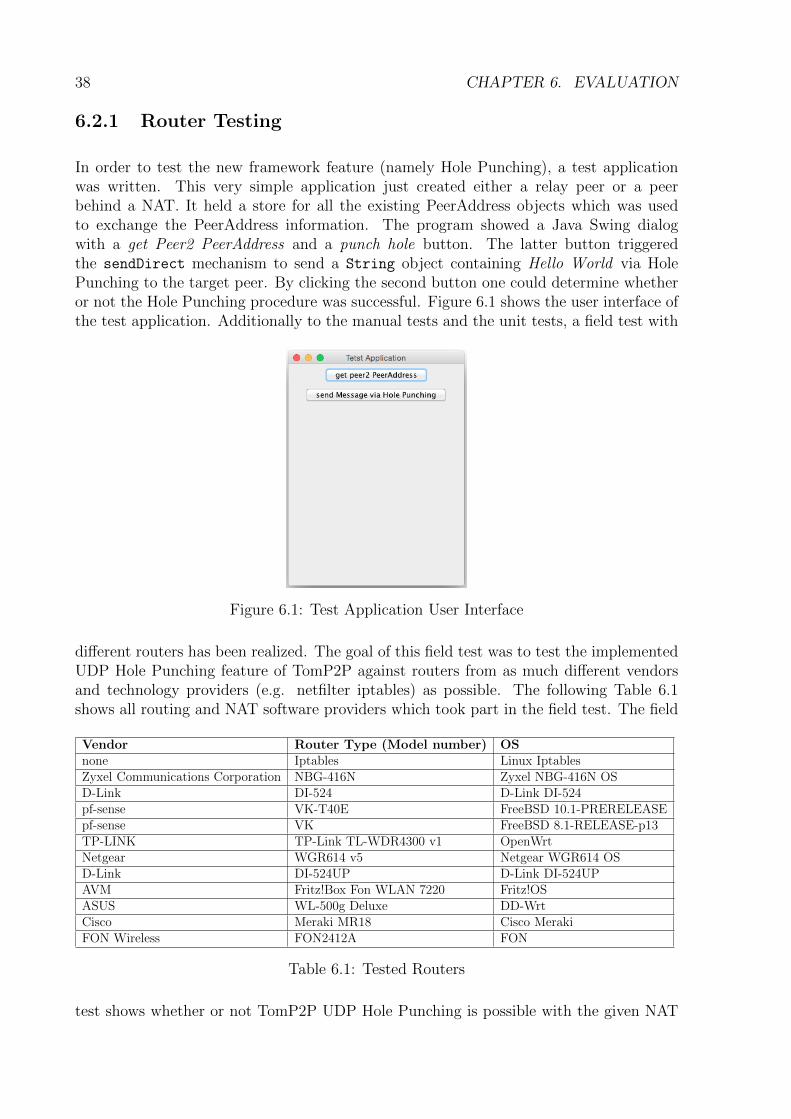
6.2.1 Router Testing
In order to test the new framework feature (namely Hole Punching), a test applicationwas written. This very simple application just created either a relay peer or a peerbehind a NAT. It held a store for all the existing PeerAddress objects which was usedto exchange the PeerAddress information. The program showed a Java Swing dialogwith a get Peer2 PeerAddress and a punch hole button. The latter button triggeredthe sendDirect mechanism to send a String object containing Hello World via HolePunching to the target peer. By clicking the second button one could determine whetheror not the Hole Punching procedure was successful. Figure 6.1 shows the user interface ofthe test application. Additionally to the manual tests and the unit tests, a field test with
Figure 6.1: Test Application User Interface
different routers has been realized. The goal of this field test was to test the implementedUDP Hole Punching feature of TomP2P against routers from as much different vendorsand technology providers (e.g. netfilter iptables) as possible. The following Table 6.1shows all routing and NAT software providers which took part in the field test. The field
Vendor Router Type (Model number) OSnone Iptables Linux IptablesZyxel Communications Corporation NBG-416N Zyxel NBG-416N OSD-Link DI-524 D-Link DI-524pf-sense VK-T40E FreeBSD 10.1-PRERELEASEpf-sense VK FreeBSD 8.1-RELEASE-p13TP-LINK TP-Link TL-WDR4300 v1 OpenWrtNetgear WGR614 v5 Netgear WGR614 OSD-Link DI-524UP D-Link DI-524UPAVM Fritz!Box Fon WLAN 7220 Fritz!OSASUS WL-500g Deluxe DD-WrtCisco Meraki MR18 Cisco MerakiFON Wireless FON2412A FON
Table 6.1: Tested Routers
test shows whether or not TomP2P UDP Hole Punching is possible with the given NAT

6.3. FLOODING VS. HOLE PUNCHING 39
device. For this field test, the test application test is used. The test is repeated five timesin order to make sure no other network influence is disturbing the application and thenetwork traffic. While testing, at three points (machines) wireshark was used to monitorthe network traffic and show that the test message is transmitted directly between thepeers. Two of those points are located on the NAT peers and one on the NAT of one of thepeers. All the capture files of the monitoring can be found in the Appendix C. A routerpasses the test only if at least four of five times the test message could be transmitteddirectly from one of the NAT peers to the other NAT peer. The test application wasdesigned to give direct visual feedback to the testing user whether or not the test messagewas transmitted in a direct way.
6.2.2 Router Testing Results
Tests described in Subsection 6.2.1 showed that nine out of twelve tested devices sup-ported UDP Hole Punching. All of the nine successful routers passed all five repeatedtest scenarios and could transmit the test message directly and without causing any error.Observations have shown that each of those NAT devices uses the source port which thepeer assigns on its private endpoint for its public endpoint.
Two of the three non-successful devices, namely the two pf-sense ones, mapped their theports in their NAT table in a random way. The reason for that is because FreeBSDNAT is based on OpenBSD [21]. In the documentation of OpenBSD NAT it says thatthe NAT will replace the private source port with a randomly chosen, unused port onthe public endpoint [25]. The third of the three non-successful devices was the D-LinkDI-524. Observations have shown, that this device also replaces the private source port ofthe peer with a randomly chosen, unused port number on the public endpoint. All of thethree non-successful devices can be called a symmetric NAT since the peers using such aNAT are unable to predict the public endpoints port number in order to tell the otherpeer its private endpoint. The traversal of symmetric NAT devices would have exceededthe boundaries of this bachelor thesis and therefore there is no implementation availablefor this NAT type. All the successful and non-sucessful NAT devices are shown in thefollowing table 6.2. A much more detailed list (with more detailed observation notes andmore detailed information about the used routers) can be found in the Appendix C ofthis bachelor thesis.
6.3 Flooding vs. Hole Punching
Compared to Flooding (simply flood the NAT with messages on all possible ports togain access to the other host behind a NAT) Hole Punching is the more resource awareapproach. Hole Punching punches only a small predefined number (at default in TomP2Pthree) of holes into the NAT and firewall. If more than one host is located behind a NATwhile using Flooding, the NAT device could possibly collapse under the large number ofrequests. But unlike the implementation of Hole Punching used in this thesis, Flooding

40 CHAPTER 6. EVALUATION
Vendor Router Type (Model Number) Hole Punching SuccessfulNone Iptables SuccessfulZyxel Communications Corporation NBG-416N SuccessfulD-Link DI-524 Non-Successfulpf-sense VK-T40E Non-Successfulpf-sense VK Non-SuccessfulTP-LINK TP-Link TL-WDR4300 v1 SuccessfulNetgear WGR614 v5 SuccessfulD-Link DI-524UP SuccessfulAVM Fritz!Box Fon WLAN 7220 SuccessfulASUS WL-500g Deluxe SuccessfulCisco Meraki MR18 SuccessfulFON Wireless FON2412A Successful
Table 6.2: Router Testing Results
would result in a higher success rate (successfully transmitting a message directly betweenNAT peers) with symmetric NAT devices.
6.4 Limitations
Although a near real world development environment (see in Chapter 5.1) was used torealize the UDP Hole Punching feature for TomP2P, this environment could never fullysimulate the behavior of the internet. In todays internet, for example, round trip timesas well as delays are much higher than in a local area network (LAN).
Also a limitation of this thesis is that the new feature only supports non-symmetric NAT.Support of symmetric NAT would might have been possible. The paper [29] explains, howsymmetric NAT could be traversed, but only if both network hosts (which are locatedbehind a NAT device) open a thousand connections.
A single Hole Punch causes at least 24 bytes of information. These 24 bytes represent asingle NAT mapping table entry including four IP addresses and four port addresses. Ad-ditionally in such a mapping table entry, there is also information about the protocol used,the time-to-live (TTL) value, the idle timer and the state information of the connection.Since it is impossible for this bachelor thesis to find out the exact number of bytes usedfor a mapping table entry, the 24 bytes are used for calculation. A mapping table entrycan not be below that number. If a thousand connections would be opened that wouldmean that (24bytes× 1000connections) 24KB of NAT mapping entries would be createdwith each Hole Punching attempt. If a peer using this method opens 50 connections toother peers via Hole Punching, this mechanism would create about 1MB of NAT mappinginformation (24KB × 1000holes × 50connections). A single Hole Punch with TomP2PHole Punching would cause at least 72 bytes of nat mapping table entries on each NAT(24bytes× 3connections). If a TomP2P NAT peer contacts 50 other NAT peers via HolePunching, it would create about 4KB (24bytes× 3holes× 50connections)

6.4. LIMITATIONS 41
Compared to the approach in the mentioned paper [29], the approach used in this thesiscauses much less mapping entries on the NAT mapping table. Additionally, 1MB of natmappings caused by Hole Punching could also possibly cause difficulties on cheaper NATdevices with less RAM and CPU power. Therefore TomP2P Hole Punching does notsupport symmetric NAT devices. The fallback scenario used in case of a symmetric NATis TCP relaying.

42 CHAPTER 6. EVALUATION

Chapter 7
Summary, Conclusion and FutureWork
7.1 Summary
The result of this bachelor thesis is a fully integrated and working UDP Hole Punchingfeature for TomP2P. Another result of this bachelor thesis is a list of compatible routersor NAT implementations from different vendors or NAT software providers. This listextends the existing list of Hole Punching compatible NAT mentioned in the papers [28]and [29]. The following Requirements were fulfilled in this thesis:
1. Must-Have
1.1. A peer behind a NAT must be able to connect to another client behind a NATusing a specific RPC (Remote Procedure Call) to connect in order to be ableto communicate with that other peer.
Fulfilled. A TomP2P peer, which is located behind a NAT device is now able toconnect to another TomP2P peer (also behind a NAT device) via Hole Punch-ing mechanism. The RPC used to fulfill the requirement is the HolePRPC. TheAbstractHolePunchStrategy makes sure that two peers behind a NAT areable to connect to each other directly.
1.2. The P2P system must be able to detect if a hole punch is possible or not inorder to know if it should use Hole Punching.
Fulfilled. The NATTypeDetection checks the NATType. Also SendBehaviour.HOLEPhas been implemented to TomP2P.
1.3. The peer must use relaying as a fallback scenario if Hole Punching does notwork because it should still be able to communicate with other peers behind
43

44 CHAPTER 7. SUMMARY, CONCLUSION AND FUTURE WORK
NATs.
Fulfilled. The implemented fallback scenario is relaying.
2. Should-Have
2.1. A client using Hole Punching should be able to use different Hole Punchingscenarios (fallback) in order to punch holes and establish a connection to an-other peer behind a NAT.
Fulfilled. There are two implemented strategies for different NAT types. Thereis PortPreservingStrategy for Full Cone NAT, Address Restricted ConeNAT, and Port Restricted Cone NAT and there is NonPreservingSequen-
tialStrategy for Symmetric NAT types which assign ports in an increasingmanner.
3. Nice-to-Have
3.1. A peer behind a NAT should be able to communicate with other peers behindNATs via Hole Punching while using a NAT machine from one of the wellknown router vendors (ASUS, Zyxel, Cisco, DLink, AVM, etc...).
Fulfilled. The TomP2P Hole Punch mechanism has been tested with twelvedifferent NAT devices (or NAT OS).
3.2. The peer should be able to support UDP based data Transfer (UDT) [16] orsome related protocol to enable a better way of communication.
Not fulfilled. See also in Section 7.3.
7.2 Conclusion
With Hole Punching, end-to-end connectivity is possible in TomP2P. Peers behind a non-symmetric NAT can now communicate directly with each other. Also Hole Punchingsaves resources on relay peers, since they only have to forward two messages (one in eachdirection) with the port information instead of relaying the whole traffic. Another advan-tage is that the user do not have to configure the used NAT device. That means, unlikeUPnP or NATPmP UDP Hole Punching works without the need of configuring softwareon the NAT device. Also the user does not need to configure any kind of port forwarding.Additionally, the firewall and the NAT can be used without the need of any restriction orconfiguration.
7.3. FUTURE WORK 45
Many users of today’s internet are using some kind of NAT device provided by their ISP.The router test mentioned in Section 6.2.1 has shown that most of the routers act ina port preserving manner, which means that they are either Full Cone, Port RestrictedCone or Restricted Cone NAT. In the future, probably an even higher number of NATsmay behave in a non symmetric way, because the NAT vendors may want to providethe possibility to use applications which use Hole Punching (e.g. Skype, Online GamingPlatforms, etc...) to the user.
But there are also drawbacks. The current version of UDP Hole Punching does not sup-port symmetric NAT behavior. That means, if one of the affected peers (which are bothbehind a NAT) uses a NAT with symmetric NAT behavior, only communication via re-laying is possible. During this thesis’s work, it also turned out to be difficult even totraverse a NAT, which assigns ports in a sequential manner. UDP Hole Punching canalso be dangerous in security terms, because relay peers are needed to forward the privateport information to the other peer. A further disadvantage of Hole Punching is that itneeds a publicly available server (like a relay peer in TomP2P) to work.
In a paper called P2P Communication Across Network Address Translators from 2005 [28],it is mentioned that 82% of the tested NAT devices supported UDP Hole Punching. Itis assumed that this number will keep on growing. But this assumption works only forso called home networks. If we take a look at a business use case, in the future therewill probably be only symmetric NAT. This, because business users are more concernedabout security issues (like man-in-the-middle attacks) than home network users. All inall, as long as the NAT behavior is not standardized, NAT traversal will keep on being aimportant issue to P2P networks like TomP2P [28].
7.3 Future Work
Implementing UDP Hole Punching is not the only step that needs to be done to gainback direct communication between peers in today’s P2P network. For possible futurework it is suggested not to implement TCP Hole Punching, because it is more difficultto realize than UDP Hole Punching and its success rate is significantly lower than thesuccess rate of UDP Hole Punching. However, what could be done in the future would bethe integration of a connection oriented protocol based on UDP like UDT (UDP-baseddata transfer) [16]. The advantage of the use of UDT would be that on top of UDP HolePunching (namely a UDP connection) a connection oriented protocol could be installed.That would mean that Hole Punching would establish the connection between two NATpeers and UDT would then keep this connection and provide a TCP like data transferfrom one NAT peer to the other.
Also for future work the support for more NAT types is recommended. At the moment,only non-symmetric NAT can be traversed since it is difficult to implement support forthese. But in a future step, partial support for symmetric could be implemented into

46 CHAPTER 7. SUMMARY, CONCLUSION AND FUTURE WORK
TomP2P (e.g. support for NAT which assign ports in an increasing way).
Additionally, the use of a permanent peer connection is recommended. There is alreadya class called PeerConnection available in TomP2P. This class cares about stable andpermanent TCP connections between two peers. Because each message, which is sentfrom one NAT peer to another NAT peer, will cause a new Hole Punch setup, a permanentUDP PeerConnection would save a high amount of resources (e.g. connection setup time)on each peer.

Bibliography
[1] Iptables Info, 2008. http://www.iptables.info/en/structure-of-iptables.
html, last visited on 13.03.2015.
[2] Git, March 2015. http://git-scm.com, last visited on 13.03.2015.
[3] Github, March 2015. https://github.org, last visited on 13.03.2015.
[4] Java, March 2015. https://www.java.com/en/download/faq/whatis_java.xml,last visited on 13.03.2015.
[5] MaidSafe Github Repository, March 2015. https://github.com/maidsafe/
MaidSafe, last visited on 23.03.2015.
[6] F. Audet and C. Jennings. Network Address Translation (NAT) Behavioral Re-quirements for Unicast UDP. BCP 127, RFC Editor, January 2007. http:
//www.rfc-editor.org/rfc/rfc4787.txt.
[7] Salman Baset and Henning Schulzrinne. An Analysis of the Skype Peer-to-PeerInternet Telephony Protocol. CoRR, abs/cs/0412017, September 2004.
[8] Dr. Thomas Bocek. TomP2P, March 2015. http://tomp2p.net, last visited on23.03.2015.
[9] S. Cheshire and M. Krochmal. NAT Port Mapping Protocol (NAT-PMP). RFC 6886,RFC Editor, April 2013. http://www.rfc-editor.org/rfc/rfc6886.txt.
[10] Microsoft Corporation. Sicherheitsanfalligkeit in Universellem Plug n’Play kann Re-motecodeausfuhrung ermoglichen (931261). Technet Article, April 2007.
[11] Wook Hyun Kwon Dong-Sung Kim, Jae-Min Lee. Design and Implementation ofHome Network Systems using UPnP Middleware for Networked Applicances, Novem-ber 2001.
[12] Allegro Software Development Corporation et al. UPnP Device Architecture 1.0.Technical Report 1.0, UPnP Forum, October 2008.
[13] Eclipse Foundation. Eclipse IDE, March 2015. http://eclipse.org/ide, last visitedon 09.03.2015.
[14] Wireshark Foundation. Wireshark, March 2015. https://www.wireshark.org/, lastvisited on 09.03.2015.
47

48 BIBLIOGRAPHY
[15] NewMedia-NET GmbH. DD-WRT, March 2015. http://www.dd-wrt.com/, lastvisited on 23.03.2015.
[16] Yunhong Gu and Robert L. Grossman. Supporting Configurable Congestion Controlin Data Transport Services. In Proceedings of the 2005 ACM/IEEE Conference onSupercomputing, SC ’05, pages 31–, Washington, DC, USA, 2005. IEEE ComputerSociety.
[17] ASUSTek Computer Inc. ASUSTek Computer Inc., March 2015. http://www.asus.com, last visited on 23.03.2015.
[18] David Irvine. MaidSafe Distributed File System. Technical report, maidsafe.netlimited, September 2010.
[19] David Irvine. MaidSafe DIstributed Hash Table. Technical report, September 2010.
[20] Patrick Kirk. The Annotated Gnutella Protocol Specification v0.4. Gnutella DeveloperForum, 1.6 edition, 2003.
[21] Michael W. Lucas. Absolute FreeBSD: The Complete Guide to FreeBSD. No StarchPress, 2nd edition, November 2007.
[22] David P. Lytle, Veronica Resendez, and Robert August. Security in the ResidentialNetwork. In Proceedings of the 33rd Annual ACM SIGUCCS Conference on UserServices, SIGUCCS ’05, pages 197–201, New York, NY, USA, 2005. ACM.
[23] netfilter.org. Iptables Firewall and Conntrack, October 2012. http://netfilter.
org, last visited on 09.03.2015.
[24] Mark O’Neill. The Internet of Things: do more devices mean more risks? ComputerFraud & Security, 2014(1):16 – 17, January 2014.
[25] OpenBSD. Network Address Translation (NAT) - How NAT Works, March 2015.http://www.openbsd.org/faq/pf/nat.html, last visited on 10.03.2015.
[26] Andy Oram. Peer-to-Peer: Harnessing the Power of Disruptive Technologies.O’Reilly & Associates, Inc., Sebastopol, CA, USA, 1st edition, March 2001.
[27] J. Rosenberg, J. Weinberger, C. Huitema, and R. Mahy. STUN - Simple Traversal ofUser Datagram Protocol (UDP) Through Network Address Translators (NATs). RFC3489, RFC Editor, March 2003. http://www.rfc-editor.org/rfc/rfc3489.txt.
[28] P. Srisuresh, B. Ford, and D. Kegel. State of Peer-to-Peer (P2P) Communicationacross Network Address Translators (NATs). RFC 5128, RFC Editor, March 2008.http://www.rfc-editor.org/rfc/rfc5128.txt.
[29] Kazuhiro Tobe, Akihiro Shimoda, and Shigeki Goto. Extended UDP Multiple HolePunching Method to Traverse Large Scale NATs. In Proceedings of the Asia-PacificAdvanced Network 2010, pages 30–36, tobe, shimo, [email protected],2010. APAN - Asia-Pacific Advanced Network.

BIBLIOGRAPHY 49
[30] Advanced Network Technology Division USA. SendIP, February 2014. http://snad.ncsl.nist.gov/ipv6/sendip.html, last visited on 09.03.2015.
[31] Kuai Xu, Feng Wang, Lin Gu, Jianhua Gao, and Yaohui Jin. Characterizing homenetwork traffic: an inside view. Personal and Ubiquitous Computing, 18(4):967–975,August 2014.

50 BIBLIOGRAPHY

Abbreviations
NAT Network Address TranslationUDP User Datagram ProtocolTCP Transport Control ProtocolRPC Remote Procedure CallCSG Communication Systems GroupNATPmP Network Address Translation Port mapping ProtocolUPnP Universal Plug and PlaySTUN Simple Traversal of UDP through NATISP Internet Service ProviderPC Personal ComputerCPU Central Processing UnitRAM Random Access MemoryOS Operating SystemDHT Distributed Hash TableIDE Integrated Development EnvironmentOSI Open Systems InterconnectionANTD Advanced Network Technology DivisionNIST National Institute for Standards and TechnologyUDT UDP based Data TransferLAN Local Area NetworkTTL Time-to-Live
51

52 ABBREVIATONS

List of Figures
3.1 Network Address Translation Example . . . . . . . . . . . . . . . . . . . . 8
3.2 Full Cone NAT [29] . . . . . . . . . . . . . . . . . . . . . . . . . . . . . . . 9
3.3 Address Restricted Cone NAT [29] . . . . . . . . . . . . . . . . . . . . . . 9
3.4 Port Restricted Code NAT [29] . . . . . . . . . . . . . . . . . . . . . . . . 10
3.5 Symmetric NAT [29] . . . . . . . . . . . . . . . . . . . . . . . . . . . . . . 10
3.6 NAT Traversal by Connection Reversal [28] . . . . . . . . . . . . . . . . . . 11
3.7 UDP Hole Punching Process [28] . . . . . . . . . . . . . . . . . . . . . . . 14
3.8 After Hole Punching [28] . . . . . . . . . . . . . . . . . . . . . . . . . . . . 14
4.1 Sequence Diagram Hole Punching . . . . . . . . . . . . . . . . . . . . . . . 19
4.2 Simplified Class Diagram, First Approach . . . . . . . . . . . . . . . . . . 20
4.3 Simplified Class Diagram, Final Design . . . . . . . . . . . . . . . . . . . . 21
5.1 The Development Environment . . . . . . . . . . . . . . . . . . . . . . . . 24
5.2 Iptables Packet Processing [1] . . . . . . . . . . . . . . . . . . . . . . . . . 26
5.3 Network Plan Overview . . . . . . . . . . . . . . . . . . . . . . . . . . . . 28
6.1 Test Application User Interface . . . . . . . . . . . . . . . . . . . . . . . . 38
53

54 LIST OF FIGURES
List of Tables
2.1 NAT Hardware/OS list with UDP Hole Punching Success rates [28] . . . . 4
6.1 Tested Routers . . . . . . . . . . . . . . . . . . . . . . . . . . . . . . . . . 38
6.2 Router Testing Results . . . . . . . . . . . . . . . . . . . . . . . . . . . . . 40
55

56 LIST OF TABLES

Listings
5.1 HolePInitiator Interface . . . . . . . . . . . . . . . . . . . . . . . . . . . 295.2 HolePStrategy Interface . . . . . . . . . . . . . . . . . . . . . . . . . . . . 305.3 The initiateHolePunch() Method . . . . . . . . . . . . . . . . . . . . . . 315.4 The replyHolePunch() Method . . . . . . . . . . . . . . . . . . . . . . . . 325.5 The doPortGuessingInitiatingPeer() Method . . . . . . . . . . . . . . 335.6 Example of Number of Punches . . . . . . . . . . . . . . . . . . . . . . . . 345.7 The checkNATType() Method . . . . . . . . . . . . . . . . . . . . . . . . . 35
57

58 LISTINGS

Appendix A
Installation Guidelines
The Hole Punching feature of this bachelor thesis is a package, namely tomp2p-nat/src/-
main/java/net.tomp2p.holep, inside of the TomP2P framework. In order to downloadTomP2P on a Computer, follow the link to the download site http://tomp2p.net/downlo-ads/.
59

60 APPENDIX A. INSTALLATION GUIDELINES
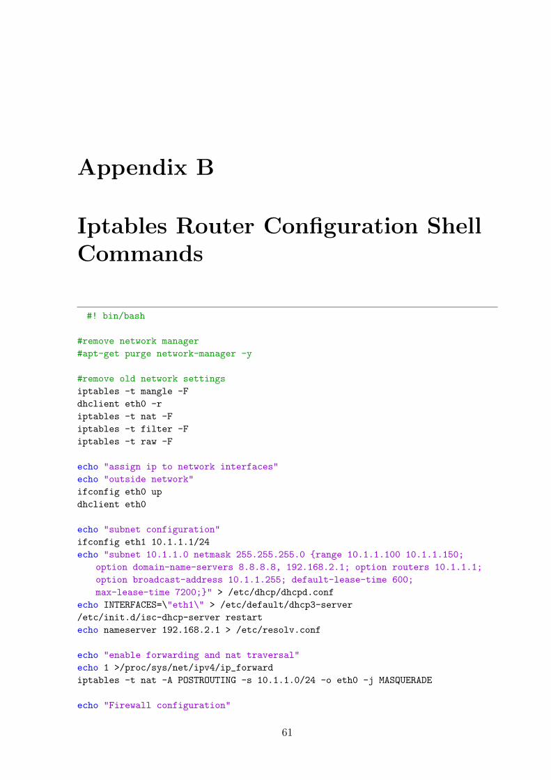
Appendix B
Iptables Router Configuration ShellCommands
#! bin/bash
#remove network manager
#apt-get purge network-manager -y
#remove old network settings
iptables -t mangle -F
dhclient eth0 -r
iptables -t nat -F
iptables -t filter -F
iptables -t raw -F
echo "assign ip to network interfaces"
echo "outside network"
ifconfig eth0 up
dhclient eth0
echo "subnet configuration"
ifconfig eth1 10.1.1.1/24
echo "subnet 10.1.1.0 netmask 255.255.255.0 {range 10.1.1.100 10.1.1.150;
option domain-name-servers 8.8.8.8, 192.168.2.1; option routers 10.1.1.1;
option broadcast-address 10.1.1.255; default-lease-time 600;
max-lease-time 7200;}" > /etc/dhcp/dhcpd.conf
echo INTERFACES=\"eth1\" > /etc/default/dhcp3-server
/etc/init.d/isc-dhcp-server restart
echo nameserver 192.168.2.1 > /etc/resolv.conf
echo "enable forwarding and nat traversal"
echo 1 >/proc/sys/net/ipv4/ip_forward
iptables -t nat -A POSTROUTING -s 10.1.1.0/24 -o eth0 -j MASQUERADE
echo "Firewall configuration"
61
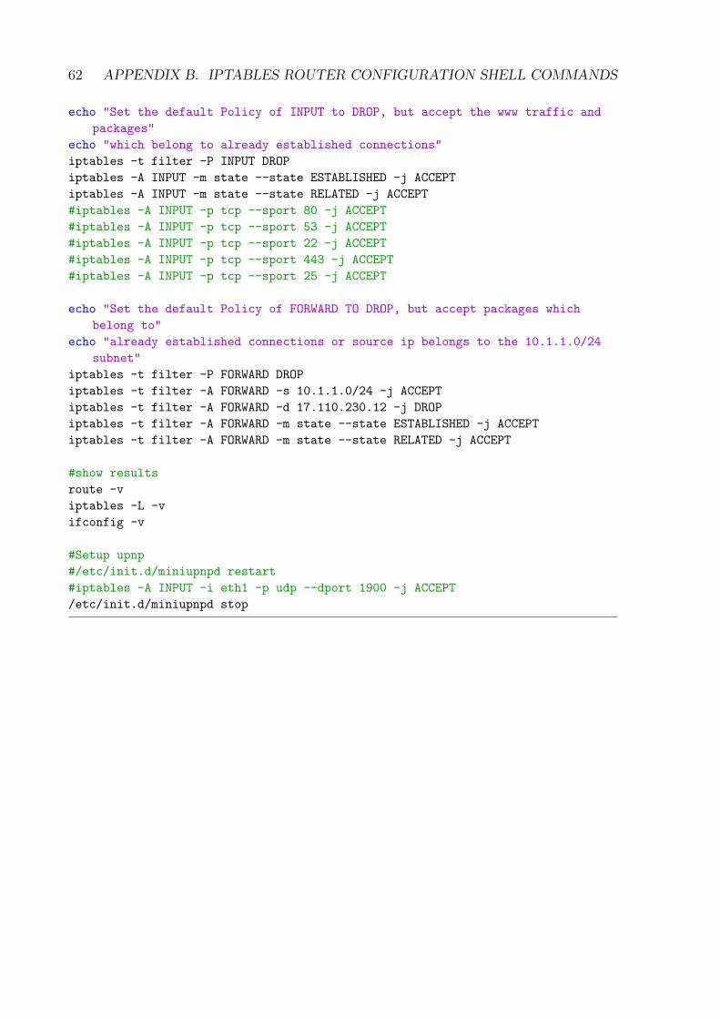
62 APPENDIX B. IPTABLES ROUTER CONFIGURATION SHELL COMMANDS
echo "Set the default Policy of INPUT to DROP, but accept the www traffic and
packages"
echo "which belong to already established connections"
iptables -t filter -P INPUT DROP
iptables -A INPUT -m state --state ESTABLISHED -j ACCEPT
iptables -A INPUT -m state --state RELATED -j ACCEPT
#iptables -A INPUT -p tcp --sport 80 -j ACCEPT
#iptables -A INPUT -p tcp --sport 53 -j ACCEPT
#iptables -A INPUT -p tcp --sport 22 -j ACCEPT
#iptables -A INPUT -p tcp --sport 443 -j ACCEPT
#iptables -A INPUT -p tcp --sport 25 -j ACCEPT
echo "Set the default Policy of FORWARD TO DROP, but accept packages which
belong to"
echo "already established connections or source ip belongs to the 10.1.1.0/24
subnet"
iptables -t filter -P FORWARD DROP
iptables -t filter -A FORWARD -s 10.1.1.0/24 -j ACCEPT
iptables -t filter -A FORWARD -d 17.110.230.12 -j DROP
iptables -t filter -A FORWARD -m state --state ESTABLISHED -j ACCEPT
iptables -t filter -A FORWARD -m state --state RELATED -j ACCEPT
#show results
route -v
iptables -L -v
ifconfig -v
#Setup upnp
#/etc/init.d/miniupnpd restart
#iptables -A INPUT -i eth1 -p udp --dport 1900 -j ACCEPT
/etc/init.d/miniupnpd stop

Appendix C
Contents of the CD
Zusfsg.txt The german version of the Abstract of this Thesis.
Abstract.txt The english version of the Abstract of this Thesis.
BachelorThesis.pdf The digital version of this Thesis.
TomP2P.zip The compressed source code of this Thesis.
UDPHolePunchingManual.txt A Manual of the use of Hole Punching of this Thesis.
RouterTest.zip A compressed version of the realized router test of this Thesis. This filecontains an excel sheet mentioning all the routers in detail and whether or not theysucceeded as well as all the wireshark .pcap files which monitored the traffic in thetest.
Intpr.pdf The intermediate presentation of this Thesis.
63