ufgs 22 16 19.26 20 large centrifugal air compressors ... 22 16 19.26 20.pdfasme b40.100 (2013)...
TRANSCRIPT

**************************************************************************USACE / NAVFAC / AFCEC / NASA UFGS- 22 16 19. 26 20 ( November 2009) - - - - - - - - - - - - - - - - - - - - - - - - - - - - - - - - - - -Pr epar i ng Act i v i t y: NAVFAC Super sedi ng UFGS- 22 16 19. 26 20 ( Apr i l 2006)
UNI FI ED FACI LI TI ES GUI DE SPECI FI CATI ONS
Ref er ences ar e i n agr eement wi t h UMRL dat ed Januar y 2018**************************************************************************
SECTI ON TABLE OF CONTENTS
DI VI SI ON 22 - PLUMBI NG
SECTI ON 22 16 19. 26 20
LARGE CENTRI FUGAL AI R COMPRESSORS ( OVER 200 HP)
11/09
PART 1 GENERAL
1. 1 REFERENCES 1. 2 GENERAL REQUI REMENTS 1. 3 SUBMI TTALS 1. 4 QUALI TY ASSURANCE 1. 4. 1 Wor k Pl an 1. 4. 2 Fact or y Test i ng Cer t i f i cat i on 1. 4. 3 Qual i f i cat i ons of Fi el d Super vi sor s 1. 4. 4 Tr ai ni ng Mat er i al 1. 4. 5 Syst em I nst al l at i on 1. 4. 6 Ai r Compr essor Syst em 1. 5 SAFETY 1. 6 EQUI PMENT ARRANGEMENT 1. 7 ELECTRI CAL REQUI REMENTS 1. 8 SUPERVI SI ON 1. 9 DEFI NI TI ONS 1. 10 I NSULATI ON 1. 11 POSTED OPERATI NG I NSTRUCTI ONS
PART 2 PRODUCTS
2. 1 MATERI ALS AND EQUI PMENT 2. 2 AI R COMPRESSOR 2. 2. 1 Manuf act ur er ' s Cer t i f i cat i ons 2. 2. 2 Guar ant eed Per f or mance 2. 2. 3 Addi t i onal Per f or mance Requi r ement s 2. 2. 3. 1 Ai r Qual i t y 2. 2. 3. 2 Sur ge Out put Pr essur e 2. 2. 3. 3 Unl oadi ng 2. 2. 3. 4 Ambi ent and I nl et Condi t i ons Oper at i ng Ranges 2. 2. 3. 5 Cr i t i cal Speeds 2. 2. 3. 6 Vi br at i on and Bal ance 2. 2. 4 El ect r i cal Ser vi ce Condi t i ons 2. 2. 4. 1 Ai r Compr essor Dr i ve Mot or 2. 2. 4. 2 Accessor y el ect r i cal Ser vi ce
SECTI ON 22 16 19. 26 20 Page 1

2. 2. 5 Compr essor Cont r ol s 2. 2. 5. 1 Two- St ep Cont r ol Mode 2. 2. 5. 2 Dual Cont r ol Mode 2. 2. 5. 3 Unl oaded Compr essor St ar t - Up 2. 2. 5. 4 El ect r i cal St ar t - Up I nt er l ocks 2. 2. 5. 5 Moni t or and Saf et y Cont r ol s 2. 2. 5. 6 Moni t or i ng I nst r ument s 2. 2. 5. 7 [ Gages on Schemat i cs 2. 2. 5. 8 Cont r ol Schemat i cs 2. 2. 6 Cont r ol Ai r Suppl y 2. 2. 7 Compr essor Desi gn Feat ur es 2. 2. 7. 1 Casi ngs 2. 2. 7. 2 Shaf t s 2. 2. 7. 3 I mpel l er s 2. 2. 7. 4 Gear s 2. 2. 7. 5 Seal s 2. 2. 7. 6 Thr ust Bear i ngs 2. 2. 7. 7 Radi al Bear i ngs 2. 2. 7. 8 I nt er cool er , Af t er cool er s, and Oi l Cool er s 2. 2. 7. 9 Lubr i cat i on Syst em 2. 2. 8 El ect r i c Mot or s 2. 2. 8. 1 Mai n El ect r i c Dr i ve Mot or 2. 2. 8. 2 Accessor y and Rel at ed Equi pment Mot or s 2. 2. 9 Cont r ol Panel 2. 2. 10 Accessor i es 2. 2. 10. 1 Cont r ol Val ves 2. 2. 10. 2 Ai r I nt ake Devi ces 2. 2. 10. 3 Compr essor Ai r Out l et Connect i ons 2. 2. 11 I nl et Ai r Fi l t er s 2. 2. 11. 1 Fi r st - St age 2. 2. 11. 2 Second- St age 2. 2. 11. 3 Thi r d- St age 2. 2. 11. 4 Fi l t er Medi a 2. 2. 12 Bypass Li ne Si l encer 2. 2. 13 I sol at i ng Pad 2. 3 AI R FLOW RATE AND PRESSURE RECORDER AND MEASUREMENT 2. 4 CARBON MONOXI DE MONI TOR 2. 4. 1 Sampl i ng Syst em 2. 4. 2 Test Syst em 2. 5 SOURCE QUALI TY CONTROL 2. 5. 1 Fact or y Test Pr ocedur es 2. 5. 2 Super vi s i on of Test i ng 2. 5. 3 Syst em Test 2. 5. 4 Appr oval of Test i ng Pr ocedur e 2. 5. 5 Cer t i f i cat i on of Per f or mance Test s
PART 3 EXECUTI ON
3. 1 I NSTALLATI ON 3. 1. 1 Manuf act ur er ' s Super v i s i on 3. 2 GENERAL REQUI REMENTS FOR I NSTALLI NG AI R COMPRESSORS 3. 2. 1 Pr ompt I nst al l at i on 3. 2. 2 St ar t - Up Ser vi ces 3. 3 FI ELD QUALI TY CONTROL 3. 3. 1 Fi el d Test Pr ocedur es 3. 3. 1. 1 Ai r Compr essor Per f or mance Test s 3. 3. 1. 2 I nst r ument at i on Test 3. 3. 1. 3 Sound Level Test s 3. 3. 1. 4 Def i c i enci es Di scover ed i n Test i ng
SECTI ON 22 16 19. 26 20 Page 2

3. 3. 1. 5 Test i ng Tol er ances 3. 3. 2 Appr oval of Test i ng Pr ocedur e 3. 4 TRAI NI NG OF GOVERNMENT PERSONNEL
- - End of Sect i on Tabl e of Cont ent s - -
SECTI ON 22 16 19. 26 20 Page 3
**************************************************************************USACE / NAVFAC / AFCEC / NASA UFGS- 22 16 19. 26 20 ( November 2009) - - - - - - - - - - - - - - - - - - - - - - - - - - - - - - - - - - -Pr epar i ng Act i v i t y: NAVFAC Super sedi ng UFGS- 22 16 19. 26 20 ( Apr i l 2006)
UNI FI ED FACI LI TI ES GUI DE SPECI FI CATI ONS
Ref er ences ar e i n agr eement wi t h UMRL dat ed Januar y 2018**************************************************************************
SECTI ON 22 16 19. 26 20
LARGE CENTRI FUGAL AI R COMPRESSORS ( OVER 200 HP)11/09
**************************************************************************NOTE: Thi s gui de speci f i cat i on cover s t he r equi r ement s f or l ar ge cent r i f ugal ai r compr essor s over 150 kW 200 hp and cer t ai n accessor i es.
Adher e t o UFC 1- 300- 02 Uni f i ed Faci l i t i es Gui de Speci f i cat i ons ( UFGS) For mat St andar d when edi t i ng t hi s gui de speci f i cat i on or pr epar i ng new pr oj ect speci f i cat i on sect i ons. Edi t t hi s gui de speci f i cat i on f or pr oj ect speci f i c r equi r ement s by addi ng, del et i ng, or r evi s i ng t ext . For br acket ed i t ems, choose appl i cabl e i t em( s) or i nser t appr opr i at e i nf or mat i on.
Remove i nf or mat i on and r equi r ement s not r equi r ed i n r espect i ve pr oj ect , whet her or not br acket s ar e present.
Comment s, suggest i ons and r ecommended changes f or t hi s gui de speci f i cat i on ar e wel come and shoul d be submi t t ed as a Cr i t er i a Change Request ( CCR) .
**************************************************************************
**************************************************************************NOTE: Cool i ng t ower s, c l osed- ci r cui t cool er s, cool i ng wat er pi pi ng, and ot her i t ems ar e not i ncl uded and must be i ncl uded i n ot her sect i ons of t he pr oj ect speci f i cat i on. CENTRI FUGAL COMPRESSORS MUST BE PERMI TTED AS AN OPTI ON I F NONLUBRI CATED ROTARY SCREW COMPRESSORS ARE SPECI FI ED I N THE PROJECT.
**************************************************************************
**************************************************************************NOTE: The f ol l owi ng i nf or mat i on shal l be shown on t he pr oj ect dr awi ngs:
1. Compr essor , accessor y equi pment , and pi pi ng ar r angement and det ai l s .
2. Equi pment f oundat i ons.
SECTI ON 22 16 19. 26 20 Page 4
3. Equi pment schedul es. I f equi pment schedul es i ncl ude oper at i ng condi t i ons f or t he compr essor , del et e t he i nf or mat i on f r om t hi s sect i on.
**************************************************************************
PART 1 GENERAL
1. 1 REFERENCES
**************************************************************************NOTE: Thi s par agr aph i s used t o l i s t t he publ i cat i ons c i t ed i n t he t ext of t he gui de speci f i cat i on. The publ i cat i ons ar e r ef er r ed t o i n t he t ext by basi c desi gnat i on onl y and l i s t ed i n t hi s par agr aph by or gani zat i on, desi gnat i on, dat e, and t i t l e. Use t he Ref er ence Wi zar d' s Check Ref er ence f eat ur e when you add a Ref er ence I dent i f i er ( RI D) out s i de of t he Sect i on' s Ref er ence Ar t i c l e t o aut omat i cal l y pl ace t he r ef er ence i n t he Ref er ence Ar t i c l e. Al so use t he Ref er ence Wi zar d' s Check Ref er ence f eat ur e t o updat e t he i ssue dat es. Ref er ences not used i n t he t ext wi l l aut omat i cal l y be del et ed f r om t hi s sect i on of t he pr oj ect speci f i cat i on when you choose t o r econci l e r ef er ences i n t he publ i sh pr i nt pr ocess.
**************************************************************************
The publ i cat i ons l i s t ed bel ow f or m a par t of t hi s speci f i cat i on t o t he ext ent r ef er enced. The publ i cat i ons ar e r ef er r ed t o wi t hi n t he t ext by t he basi c desi gnat i on onl y.
AMERI CAN GEAR MANUFACTURERS ASSOCI ATI ON ( AGMA)
AGMA 2011 ( 2014B) Cyl i ndr i cal Wor mgear i ng Tol er ance and I nspect i on Met hods
ANSI / AGMA 2009 ( 2001B; R 2008) Bevel Gear Cl assi f i cat i on, Tol er ances, and I nspect i on Met hods
AMERI CAN PETROLEUM I NSTI TUTE ( API )
API St d 672 ( 2004; Er r at a 2007; Er r at a 2010) Packaged, I nt egr al l y Gear ed Cent r i f ugal Ai r Compr essor s f or Pet r ol eum, Chemi cal , and Gas I ndust r y Ser vi ces
ASME I NTERNATI ONAL ( ASME)
ASME B1. 20. 1 ( 2013) Pi pe Thr eads, Gener al Pur pose ( I nch)
ASME B16. 1 ( 2015) Gr ay I r on Pi pe Fl anges and Fl anged Fi t t i ngs Cl asses 25, 125, and 250
ASME B16. 5 ( 2017) Pi pe Fl anges and Fl anged Fi t t i ngs NPS 1/ 2 Thr ough NPS 24 Met r i c/ I nch St andar d
SECTI ON 22 16 19. 26 20 Page 5

ASME B40. 100 ( 2013) Pr essur e Gauges and Gauge Attachments
ASME BPVC SEC VI I I D1 ( 2015) BPVC Sect i on VI I I - Rul es f or Const r uct i on of Pr essur e Vessel s Di v i s i on 1
ASME PTC 10 ( 1997; R 2014) Per f or mance Test Code on Compr essor s and Exhaust er s
ASTM I NTERNATI ONAL ( ASTM)
ASTM A36/ A36M ( 2014) St andar d Speci f i cat i on f or Car bon St r uct ur al St eel
ASTM B111/ B111M ( 2011) St andar d Speci f i cat i on f or Copper and Copper - Al l oy Seaml ess Condenser Tubes and Fer r ul e St ock
ASTM B171/ B171M ( 2012) St andar d Speci f i cat i on f or Copper - Al l oy Pl at e and Sheet f or Pr essur e Vessel s, Condenser s and Heat Exchanger s
ASTM B209 ( 2014) St andar d Speci f i cat i on f or Al umi num and Al umi num- Al l oy Sheet and Pl at e
ASTM B209M ( 2014) St andar d Speci f i cat i on f or Al umi num and Al umi num- Al l oy Sheet and Pl at e ( Met r i c)
ASTM C553 ( 2013) St andar d Speci f i cat i on f or Mi ner al Fi ber Bl anket Ther mal I nsul at i on f or Commer ci al and I ndust r i al Appl i cat i ons
ASTM E84 ( 2017) St andar d Test Met hod f or Sur f ace Bur ni ng Char act er i st i cs of Bui l di ng Materials
COMPRESSED GAS ASSOCI ATI ON ( CGA)
CGA G- 7. 1 ( 2011) Commodi t y Speci f i cat i on f or Ai r ; 5t h Edi t i on
I NSTI TUTE OF ELECTRI CAL AND ELECTRONI CS ENGI NEERS ( I EEE)
I EEE 112 ( 2004) St andar d Test Pr ocedur e f or Pol yphase I nduct i on Mot or s and Gener at or s
I NTERNATI ONAL ORGANI ZATI ON FOR STANDARDI ZATI ON ( I SO)
I SO 2151 ( 2004) Acoust i cs - Noi se Test Code f or Compr essor s and Vacuum Pumps - Engi neer i ng Met hod ( Gr ade 2)
NATI ONAL ELECTRI CAL MANUFACTURERS ASSOCI ATI ON ( NEMA)
NEMA I CS 2 ( 2000; R 2005; Er r at a 2008) I ndust r i al Cont r ol and Syst ems Cont r ol l er s, Cont act or s, and Over l oad Rel ays Rat ed 600 V
NEMA I CS 6 ( 1993; R 2016) I ndust r i al Cont r ol and
SECTI ON 22 16 19. 26 20 Page 6

Syst ems: Encl osur es
NEMA MG 1 ( 2016; SUPP 2016) Mot or s and Gener at or s
U. S. DEPARTMENT OF DEFENSE ( DOD)
MIL-A-3316 ( 1987; Rev C; Am 2 1990) Adhesi ves, Fi r e- Resi st ant , Ther mal I nsul at i on
MIL-PRF-17331 ( 2013; Rev K) Lubr i cat i ng Oi l , St eam Tur bi ne and Gear , Moder at e Ser vi ce
MIL-T-19646 ( 1990; Rev A) Ther momet er , Gas Act uat ed, Remot e Readi ng
U. S. NATI ONAL ARCHI VES AND RECORDS ADMI NI STRATI ON ( NARA)
29 CFR 1910. 219 Mechani cal Power Tr ansmi ssi on Appar at us
1. 2 GENERAL REQUI REMENTS
Sect i on 23 03 00. 00 20 BASI C MECHANI CAL MATERI ALS AND METHODS, appl i es t o t hi s sect i on except as speci f i ed her ei n.
1. 3 SUBMITTALS
**************************************************************************NOTE: Revi ew Submi t t al Descr i pt i on ( SD) def i ni t i ons i n Sect i on 01 33 00 SUBMI TTAL PROCEDURES and edi t t he f ol l owi ng l i s t t o r ef l ect onl y t he submi t t al s r equi r ed f or t he pr oj ect .
The Gui de Speci f i cat i on t echni cal edi t or s have desi gnat ed t hose i t ems t hat r equi r e Gover nment appr oval , due t o t hei r compl exi t y or cr i t i cal i t y , wi t h a " G" . Gener al l y, ot her submi t t al i t ems can be r evi ewed by t he Cont r act or ' s Qual i t y Cont r ol Syst em. Onl y add a “ G” t o an i t em, i f t he submi t t al i s suf f i c i ent l y i mpor t ant or compl ex i n cont ext of t he pr oj ect .
For submi t t al s r equi r i ng Gover nment appr oval on Ar my pr oj ect s, a code of up t o t hr ee char act er s wi t hi n t he submi t t al t ags may be used f ol l owi ng t he " G" desi gnat i on t o i ndi cat e t he appr ovi ng aut hor i t y. Codes f or Ar my pr oj ect s usi ng t he Resi dent Management Syst em ( RMS) ar e: " AE" f or Ar chi t ect - Engi neer ; " DO" f or Di st r i c t Of f i ce ( Engi neer i ng Di v i s i on or ot her or gani zat i on i n t he Di st r i c t Of f i ce) ; " AO" f or Ar ea Of f i ce; " RO" f or Resi dent Of f i ce; and " PO" f or Pr oj ect Of f i ce. Codes f ol l owi ng t he " G" t ypi cal l y ar e not used f or Navy, Ai r For ce, and NASA pr oj ect s.
Use t he " S" c l assi f i cat i on onl y i n SD- 11 Cl oseout Submi t t al s. The " S" f ol l owi ng a submi t t al i t em i ndi cat es t hat t he submi t t al i s r equi r ed f or t he Sust ai nabi l i t y eNot ebook t o f ul f i l l f eder al l y mandat ed sust ai nabl e r equi r ement s i n accor dance wi t h
SECTI ON 22 16 19. 26 20 Page 7

Sect i on 01 33 29 SUSTAI NABI LI TY REPORTI NG.
Choose t he f i r st br acket ed i t em f or Navy, Ai r For ce and NASA pr oj ect s, or choose t he second br acket ed i t em f or Ar my pr oj ect s.
**************************************************************************
Gover nment appr oval i s r equi r ed f or submi t t al s wi t h a " G" desi gnat i on; submi t t al s not havi ng a " G" desi gnat i on ar e [ f or Cont r act or Qual i t y Cont r ol appr oval . ] [ f or i nf or mat i on onl y. When used, a desi gnat i on f ol l owi ng t he " G" desi gnat i on i dent i f i es t he of f i ce t hat wi l l r evi ew t he submi t t al f or t he Gover nment . ] Submi t t al s wi t h an " S" ar e f or i ncl usi on i n t he Sust ai nabi l i t y eNot ebook, i n conf or mance t o Sect i on 01 33 29 SUSTAI NABI LI TY REPORTI NG. Submi t t he f ol l owi ng i n accor dance wi t h Sect i on 01 33 00 SUBMI TTAL PROCEDURES:
SD- 02 Shop Dr awi ngs
Ai r compr essor syst em
I ncl ude wi r i ng di agr ams of t he ai r compr essor wi t h al l accessor i es. The mi ni mum accept abl e scal e i s [ 1: 50 1/ 4 i nch t o one f oot ] [ _____] .
SD- 03 Pr oduct Dat a
**************************************************************************NOTE: I ncl ude car bon monoxi de moni t or i n syst ems whi ch ar e used f or br eat hi ng ai r per DM 3. 5, Sect i on 3.
**************************************************************************
Ai r compr essor
Ai r i nt ake devi ces
Bypass l i ne s i l encer
Ai r f l ow r at e and pr essur e r ecor der
[ Car bon monoxi de moni t or ]
Submi t manuf act ur er ' s cat al og dat a f or compr essor and auxi l i ar y equi pment i n t he f or mat pr ovi ded i n API St d 672, Appendi x A. Submi t al l appl i cabl e i nf or mat i on. For ai r compr essor , i ncl ude af t er cool er , i nt er cool er s, oi l cool er , l ubr i cat i on syst em, and cont r ol val ves. Submi t ai r compr essor and i nt er cool er per f or mance cur ves at speci f i ed summer and wi nt er desi gn condi t i ons.
SD- 06 Test Repor t s
Ai r compr essor per f or mance t est s
Bal ance t est s
Sound l evel and r un- i n t est s
Obt ai n appr oval pr i or t o shi ppi ng compr essor .
SECTI ON 22 16 19. 26 20 Page 8

Ai r compr essor per f or mance t est s
I nst r ument at i on t est
Sound l evel t est s
Ai r compr essor syst em t est s
The t est super vi sor shal l cer t i f y per f or mance by t est t o be i n compl i ance wi t h speci f i cat i ons.
SD- 07 Cer t i f i cat es
Ai r compr essor syst em
Ai r compr essor syst em i nst al l at i on
Wor k pl an
Fact or y t est pr ocedur es
Fact or y t est i ng cer t i f i cat i on
Qual i f i cat i ons of f i el d super vi sor s
Fi el d t est pr ocedur es
Tr ai ni ng mat er i al
SD- 10 Oper at i on and Mai nt enance Dat a
**************************************************************************NOTE: Obt ai n appr oval of equi pment wi t h pr opr i et ar y mai nt enance r equi r ement s f r om t he appr opr i at e cont r act s of f i ce.
**************************************************************************
Ai r compr essor syst em, Dat a Package 3
Submi t i n accor dance wi t h Sect i on 01 78 23 OPERATI ON AND MAI NTENANCE DATA.
SD- 11 Cl oseout Submi t t al s
Post ed oper at i ng i nst r uct i ons f or ai r compr essor
Submi t t ext .
1. 4 QUALI TY ASSURANCE
1. 4. 1 Wor k Pl an
Submi t a wr i t t en schedul e of dat es of i nst al l at i on, st ar t - up, checkout , and t est of equi pment .
1. 4. 2 Fact or y Test i ng Cer t i f i cat i on
Submi t a st at ement t hat t he ai r compr essor f act or y i s equi pped t o per f or m al l r equi r ed f act or y t est s. Submi t i n accor dance wi t h par agr aph ent i t l ed
SECTI ON 22 16 19. 26 20 Page 9

" Manuf act ur er ' s Cer t i f i cat i ons. "
1. 4. 3 Qual i f i cat i ons of Fi el d Super vi sor s
Submi t t he name and cer t i f i ed wr i t t en r esume of t he engi neer or t echni c i an, l i s t i ng educat i on, f act or y t r ai ni ng and i nst al l at i on, st ar t - up, and t est i ng super vi s i on exper i ence f or at l east t wo pr oj ect s i nvol v i ng compr essor s s i mi l ar t o t hose i n t hi s cont r act .
1. 4. 4 Tr ai ni ng Mat er i al
Submi t a det ai l ed t r ai ni ng pr ogr am syl l abus f or t r ai ni ng of gover nment per sonnel , i ncl udi ng i nst r uct i onal mat er i al s at l east t hr ee weeks pr i or t o st ar t of t est s.
1. 4. 5 Syst em I nst al l at i on
Submi t cer t i f i cat i on of ai r compr essor syst em per f or mance conf or mi ng t o ASME PTC 10 and ASME BPVC SEC VI I I D1. Submi t cer t i f i cat i on of pr oper syst em i nst al l at i on i n accor dance wi t h par agr aph ent i t l ed " Super vi s i on. "
1. 4. 6 Ai r Compr essor Syst em
Submi t oper at i on and mai nt enance dat a i n accor dance wi t h Sect i on 01 78 23 OPERATI ON AND MAI NTENANCE DATA. Dat a shal l cont ai n i nf or mat i on r equi r ed f or mai nt enance and r epai r and shal l cont ai n no evi dence t hat pr opr i et ar y mai nt enance ar r angement s wi t h t he manuf act ur er wi l l be necessar y. Compr essor s whi ch wi l l r equi r e pr opr i et ar y mai nt enance ar r angement wi t h t he manuf act ur er r equi r e Gover nment r evi ew and appr oval . The compr essor s may be di sappr oved i f c i r cumst ances do not j ust i f y appr oval of compr essor s wi t h l i mi t ed avai l abi l i t y of mai nt enance.
1. 5 SAFETY
Const r uct al l component s of t he uni t i n accor dance wi t h t he r equi r ement s of OSHA 29 CFR 1910. 219. Requi r ement s i ncl ude shaf t coupl i ng guar ds as speci f i ed i n Sect i on 23 03 00. 00 20 BASI C MECHANI CAL MATERI ALS AND METHODS, t her mal i nsul at i on and j acket i ng wi t h manuf act ur er st andar d cover i ng or al umi num sheet of al l sur f aces at 52 degr ees C 125 degr ees F and hi gher wi t hi n a hei ght of 2. 10 m 7 f eet f r om f l oor l evel , and use of el ect r i cal saf et y devi ces. Ther mal i nsul at i on, f ur ni shed by equi pment manuf act ur er , shal l conf or m t o ASTM C553, Type I ( f l exi bl e r esi l i ent ) , Cl ass B- 5 ( up t o 204 degr ees C 400 degr ees F) , 32 kg/ m3 2 pcf nomi nal . Cement i nsul at i on t o sur f ace wi t h MIL-A-3316 , Cl ass 2, adhesi ve and f ast en wi t h 16 gage wi r e bands at maxi mum 405 mm 16 i nches on cent er spaci ng. Cover i nsul at i on wi t h ASTM B209M ASTM B209 sheet al umi num j acket . The t her mal i nsul at i on i s r equi r ed f or uni t wi t h separ at e i nt er cool er and af t er cool er uni t s.
1. 6 EQUI PMENT ARRANGEMENT
Ar r angement sel ect ed shal l mai nt ai n 0. 9 m 3 f oot c l ear ance f or access passage and 1. 20 m 4 f oot c l ear ance f or per sonnel t o oper at e equi pment . Ther e ar e subst ant i al physi cal and connect i on poi nt di f f er ences among t he sever al ai r compr essor s whi ch compl y wi t h t hi s speci f i cat i on. The Cont r act or shal l be r esponsi bl e f or sel ect i ng equi pment and submi t t i ng ar r angement dr awi ngs cover i ng r equi r ed changes f or appr oval by t he Cont r act i ng Of f i cer . Changes f r om t he equi pment ar r angement shown on t he cont r act dr awi ngs shal l be per f or med by t he Cont r act or at no addi t i onal cost t o t he Gover nment .
SECTI ON 22 16 19. 26 20 Page 10

1. 7 ELECTRI CAL REQUI REMENTS
Compl y wi t h t he r equi r ement s of Sect i on 26 20 00 I NTERI OR DI STRI BUTI ON SYSTEM, [ and [ _____] ] .
1. 8 SUPERVISION
The Cont r act or shal l obt ai n t he ser vi ces of a qual i f i ed engi neer or t echni c i an f r om t he compr essor manuf act ur er t o super vi se i nst al l at i on, st ar t - up, and t est i ng of t he compr essor . Af t er sat i sf act or y i nst al l at i on of t he equi pment , t he engi neer or t echni c i an shal l pr ovi de a s i gned cer t i f i cat i on t hat t he equi pment i s i nst al l ed i n accor dance wi t h t he manuf act ur er ' s r ecommendat i ons.
1. 9 DEFINITIONS
Conf or m t o API St d 672 and t he f ol l owi ng:
Compr essor power i s shaf t power at shaf t coupl i ng, i ncl udi ng al l aer odynami c and mechani cal l osses.
1. 10 INSULATION
Ther mal and acoust i cal i nsul at i on shal l have f l ame spr ead r at i ng not hi gher t han 75, and smoke devel oped r at i ng not hi gher t han 150 when t est ed i n accor dance wi t h ASTM E84.
1. 11 POSTED OPERATI NG I NSTRUCTI ONS
Pr ovi de f or ai r compr essor . I ncl ude st ar t - up and shut down sequence instructions.
PART 2 PRODUCTS
2. 1 MATERI ALS AND EQUI PMENT
Mat er i al s and equi pment compl et e wi t h accessor i es shal l be sel ect ed by t he Cont r act or f or per f or mance compat i bi l i t y .
2. 2 AI R COMPRESSOR
The ai r compr essor s shal l be t he packaged, i nt egr al l y gear ed, cent r i f ugal t ype. I ncl ude t he el ect r i c mot or dr i ver , i nt egr al gear s and cases, st aged compr essor s, i nt er cool er s and moi st ur e separ at or s, af t er cool er s and moi st ur e separ at or s, i nst r ument s, cont r ol s, pr essur e l ubr i cat i on syst em wi t h pr el ubr i cat i on pump and shaf t - dr i ven l ubr i cat i on pump, st eel base and accessor i es. The af t er cool er s may be mount ed separ at el y t o meet t he per f or mance r equi r ement s.
2. 2. 1 Manuf act ur er ' s Cer t i f i cat i ons
The manuf act ur er shal l cer t i f y t hat t he ai r compr essor s pr oposed ar e of t he same desi gn, const r uct i on, and f r ame si ze, and of equal or not mor e t han 10 per cent smal l er i n capaci t y as compr essor s whi ch have been i n sat i s f act or y cont i nuous ser vi ce f or at l east 2 year s at not l ess t han t wo l ocat i ons. Fur ni sh t he name of t he owner , t he addr ess of t he i nst al l at i on, and t he name of a per son at t he i nst al l at i on who can be cont act ed f or ver i f i cat i on. The manuf act ur er shal l al so cer t i f y t hat t he f act or y i s equi pped t o per f or m
SECTI ON 22 16 19. 26 20 Page 11

al l r equi r ed f act or y t est s.
2. 2. 2 Guar ant eed Per f or mance
**************************************************************************NOTE: Desi gner shoul d f ur ni sh r equi r ed i nf or mat i on t o compl et e t he speci f i cat i on.
**************************************************************************
a. Net Compr essed Ai r Out put ( Al l seal l osses shal l be consi der ed i nt er nal and not i ncl uded i n t he net out put ) ( Mi nus zer o pl us 4 per cent ) : [ _____] l i t er s per second ( L/ s) [ _____] SCFM
b. Out put Pr essur e I mmedi at el y Downst r eam of Af t er cool er ( Mi nus zer o pl us 4 per cent ) : 862 kPa ( gage) 125 psi g
c. Out put Ai r Maxi mum Temper at ur e Downst r eam of Af t er cool er : 38 degr ees C 100 degr ees F
d. I nl et Ai r Pr essur e at Fi r st St age: [ _____] kPa ( absol ut e) psi g
e. I nl et Ai r Temper at ur e at Fi r st St age: [ _____] degr ees C F
f . I nl et Ai r Fi l t r at i on Ef f i c i ency: 99. 9 per cent of 0. 5 mi cr omet er s i ze
g. Bar omet r i c Pr essur e: [ _____] kPa ( absol ut e) psi g
h. Rel at i ve Humi di t y: [ _____] per cent
i . Cool i ng Wat er I nl et Temper at ur e: [ _____] degr ees C F
j . Tot al Cool i ng Wat er Fl ow Rat e: [ _____] L/ s gpm
k. Maxi mum Cool i ng Wat er Pr essur e Dr op Thr ough t he Compr essor and Any I nt er cool er , Af t er cool er , or Oi l Cool er : [ _____] [ 55 kPa] [ 8 psi ]
l . Maxi mum Compr essor Power Requi r ed. ( Pl us or mi nus 4 per cent ) : [ _____] kW hp
m. Unl oaded Compr essor Power and Compr essor I nt er connect i ons: [ _____] kW hp
n. Maxi mum sound l evel s one met er hor i zont al f r om compr essor and 1. 5 met er s 5 f eet above f l oor as measur ed per I SO 2151 Test Code f or t he Measur ement of Sound f r om Pneumat i c Equi pment : 84 dBA, 90 dB f or any oct ave band.
2. 2. 3 Addi t i onal Per f or mance Requi r ement s
2. 2. 3. 1 Ai r Qual i t y
Ai r at compr essor i nt ake wi l l be consi der ed br eat hi ng ai r qual i t y conf or mi ng t o CGA G- 7. 1, Type I , Gr ade D or bet t er . Ai r compr essor s shal l i nt r oduce no mat er i al , gases, or par t i c l es, or chemi cal l y al t er any mat er i al s t hat wi l l adver sel y af f ect or r educe t he qual i t y of t he ai r passi ng t hr ough t he uni t .
SECTI ON 22 16 19. 26 20 Page 12

2. 2. 3. 2 Sur ge Out put Pr essur e
API St d 672, par agr aph 2. 1. 12.
2. 2. 3. 3 Unloading
The compr essor shal l be desi gned t o unl oad pr i or t o sur ge l i mi t . The sur ge l i mi t shal l not occur at a capaci t y gr eat er t han 70 per cent of t he guar ant ee poi nt capaci t y. Unl oaded compr essor power shal l not exceed 20 per cent of f ul l l oad power .
2. 2. 3. 4 Ambi ent and I nl et Condi t i ons Oper at i ng Ranges
**************************************************************************NOTE: Desi gner shoul d f ur ni sh r equi r ed i nf or mat i on t o compl et e t he speci f i cat i on.
**************************************************************************
Al l owi ng f or r at i onal engi neer i ng per f or mance adj ust ment s due t o var i at i ons i n ambi ent and i nl et condi t i ons, t he compr essor shal l be desi gned, equi pped, and f ur ni shed t o be f ul l y oper at i onal wi t hout abnor mal wear t hr oughout t he ent i r e r ange bet ween and i ncl udi ng t he l i mi t s of t he wi nt er and summer desi gn condi t i ons speci f i ed.
a. Summer Desi gn Condi t i ons:
I nl et Ai r : [ _____] degr ees C F dr y bul b and [ _____] degr ees C F wet bul b t emper at ur es, [ _____] per cent r el at i ve humi di t y
I nl et Cool i ng Wat er : [ _____] degr ees C F
Ambi ent Compr essor Room Temper at ur e: [ _____] degr ees C F
Bar omet r i c Pr essur e: [ _____] kPa ( absol ut e) psi g
b. Wi nt er ( Low Ambi ent ) Desi gn Condi t i ons:
I nl et Ai r : [ _____] degr ees C F dr y bul b and [ _____] degr ees C F wet bul b t emper at ur es, [ _____] per cent r el at i ve humi di t y
I nl et Cool i ng Wat er : [ _____] degr ees C F
Ambi ent Compr essor Room Temper at ur e: [ _____] degr ees C F
Bar omet r i c Pr essur e: [ _____] kPa ( absol ut e) psi g.
2. 2. 3. 5 Cr i t i cal Speeds
Conf or m t o API St d 672, par agr aph ent i t l ed " Cr i t i cal Speed. "
2. 2. 3. 6 Vi br at i on and Bal ance
Conf or m t o API St d 672, par agr aphs ent i t l ed " Vi br at i on and Bal ance. "
2. 2. 4 El ect r i cal Ser vi ce Condi t i ons
2. 2. 4. 1 Ai r Compr essor Dr i ve Mot or
[ _____] vol t s, 3 phase, 3 wi r e, 60 her t z el ect r i cal ser vi ce.
SECTI ON 22 16 19. 26 20 Page 13

2. 2. 4. 2 Accessor y el ect r i cal Ser vi ce
**************************************************************************NOTE: Change accessor y vol t ages i f r equi r ed f or s i t e condi t i ons.
**************************************************************************
See Tabl e I .
TABLE I - COMPRESSOR ACCESSORY ELECTRI CAL SERVI CE SCHEDULE
Item Voltage Phase Frequency
Cont r ol Power and Mot or s under 3/ 8 kW
120 1 60 Hz
Accessor y Power 460 3 60 Hz
TABLE I - COMPRESSOR ACCESSORY ELECTRI CAL SERVI CE SCHEDULE
Item Voltage Phase Frequency
Cont r ol Power and Mot or s under 1/ 2 hp
120 1 60 Hz
Accessor y Power 460 3 60 Hz
2. 2. 5 Compr essor Cont r ol s
Pr ovi de compl et e pneumat i c l oad r ange cont r ol syst em wi t h each compr essor wi t h a manual l y sel ect abl e capabi l i t y f or t wo modes of l oad r ange cont r ol as speci f i ed. Pr ovi de addi t i onal el ect r i cal , el ect r o- pneumat i c, or sol i d st at e el ect r oni c cont r ol s f or ot her speci f i ed cont r ol and moni t or f unct i ons. Al l cont r ol s shal l conf or m t o NEMA I CS 2 as sel ect ed by t he compr essor manuf act ur er . Cont r ol syst em encl osur e shal l conf or m t o NEMA I CS 6. Cont r ol s shal l be sui t abl e f or i ndi v i dual oper at i on of t he compr essor or par al l el oper at i on wi t h one or mor e ot her compr essor s.
2. 2. 5. 1 Two- St ep Cont r ol Mode
The t wo- st ep cont r ol mode shal l act uat e t he compr essor suct i on i nl et cont r ol val ve t o ei t her a f ul l open posi t i on or t o a f ul l c l osed posi t i on i n accor dance wi t h speci f i ed, adj ust abl e pr essur e set t i ngs. The pr essur e set t i ngs shal l be an adj ust abl e band wi dt h pl us and mi nus per cent age of an adj ust abl e out put gage pr essur e set poi nt . The compr essed ai r out put gage set poi nt shal l be adj ust abl e i n t he r ange of 724 t o 862 kPa 105 t o 125 psi g, and t he gage pr essur e sensor measur ement f or t hi s set poi nt shal l be made downst r eam of t he af t er cool er . The adj ust abl e band wi dt h about t he set poi nt shal l be f r om pl us or mi nus 2 1/ 2 per cent t o pl us or mi nus 5 per cent . Cont r ol s shal l c l ose t he compr essor i nl et val ve at t he hi gh pr essur e l i mi t of t he band wi dt h and si mul t aneousl y open a bypass vent val ve whi ch shal l al so be pr ovi ded. Cont r ol s shal l open t he compr essor i nl et val ve at t he l ow pr essur e l i mi t of t he band wi dt h and si mul t aneousl y c l ose t he bypass vent val ve.
SECTI ON 22 16 19. 26 20 Page 14

2. 2. 5. 2 Dual Cont r ol Mode
A pr essur e r egul at i on cont r ol mode shal l be f ur ni shed t o cont r ol compr essor out put pr essur e t o wi t hi n pl us or mi nus one per cent of an adj ust abl e out put pr essur e set poi nt . Pr ovi de an adj ust ment r ange of 724 t o 862 kPa 105 t o 125 psi g. When t he compr essor oper at es at capaci t i es above sur ge l i mi t unl oad set t i ng and bel ow maxi mum f l ow st onewal l condi t i ons, t he cont r ol syst em shal l t hr ot t l e f l ow at t he compr essor suct i on i nl et cont r ol val ve i n r esponse t o i ncr easi ng di schar ge pr essur e due t o decr eased demand f or compr essed ai r . At l ower demand, pr i or t o r eachi ng sur ge l i mi t at a f l ow capaci t y not mor e t han 70 per cent of guar ant ee poi nt capaci t y, t he compr essor shal l unl oad by c l osi ng t he compr essor i nl et suct i on cont r ol val ve and si mul t aneousl y openi ng t he bypass vent val ve. Use of t he bypass vent val ve al one t o achi eve pr essur e cont r ol by a modul at i on t echni que of spi l l i ng excess ai r i s pr ohi bi t ed. At t he l ow di schar ge pr essur e l i mi t , t he i nl et val ve shal l open and t he bypass vent val ve shal l c l ose t o l oad t he compr essor .
2. 2. 5. 3 Unl oaded Compr essor St ar t - Up
Each of t he t wo pneumat i c cont r ol mode syst ems shal l have pr ovi s i on f or st ar t - up of t he compr essor i n t he unl oaded cont r ol set t i ng wi t h t he compr essor i nl et val ve c l osed and t he bypass val ve open.
2. 2. 5. 4 El ect r i cal St ar t - Up I nt er l ocks
The manual st ar t i ng c i r cui t of each compr essor shal l have i nt er l ocks t o pr event st ar t i ng unt i l pr e- l ubr i cat i on pump oi l pr essur e and cool i ng wat er pump wat er f l ow have been est abl i shed t o t he r equi r ed val ues f or saf e oper at i on as det er mi ned by t he compr essor manuf act ur er .
2. 2. 5. 5 Moni t or and Saf et y Cont r ol s
Pr ovi de suppl ement ar y el ect r i c , el ect r o- pneumat i c, or sol i d st at e el ect r oni c cont r ol s t o pr ovi de al ar m and shut down r equi r ement s, pl us i nt er l ocks wi t h accessor i es. Requi r ement s ar e as f ol l ows:
a. Shut down r equi r ement s shal l cause t he cont r ol l ed compr essor t o shut down, ener gi ze al ar ms, and l i ght l abel ed r ed l i ght s.
b. Al ar m onl y r equi r ement s shal l not cause t he cont r ol l ed compr essor t o shut down, but shal l sound t he same al ar ms and l i ght l abel ed amber lights.
c. Li ght onl y r equi r ement s shal l not cause t he cont r ol l ed compr essor t o shut down, but shal l l i ght l abel ed amber l i ght s.
d. The i ndi v i dual moni t or and saf et y cont r ol s shal l be as shown on Tabl e 2.
TABLE 2 - MONI TOR AND SAFETY CONTROL SCHEDULE
Item Li ght andShutdown
IndicatingAlarm
Li ght Onl y
SECTI ON 22 16 19. 26 20 Page 15

1. Hi gh Di schar ge Ai r Temper at ur e 135 degr ees C 275 degr ees F
Yes Yes -
2. Hi gh I nt er cool er Di schar ge Wat er Temper at ur e, Each I nt er cool er
No Yes -
3. Hi gh Af t er cool er Di schar ge Wat er Temperature
No Yes -
4. Hi gh Cool i ng Wat er Suppl y Temper at ur e No Yes -
5. Hi gh Lube Oi l Temper at ur e Yes Yes -
6. Low Lube Oi l Pr essur e Yes Yes -
7. Low Cool i ng Wat er Fl ow No Yes -
8. Low Oi l Reser voi r Level No Yes -
9. Hi gh Condensat e Level I nt er cool er ( wi r ed t o one l i ght )
Yes Yes -
10. Vi br at i on Moni t or s Each Pi ni on Yes Yes -
11. Sur ge Li mi t Appr oach Yes Yes -
12. Hi gh Mot or St at or Temper at ur e Yes Yes -
13. Hi gh Condensat e Level Af t er cool er No No Yes
14. Hi gh I nl et Pr essur e Dr op Acr oss I nl et Ai r Fi l t er s ( combi ned, 3 st age)
No Yes -
15. Hi gh CO Level Yes Yes -
2. 2. 5. 6 Moni t or i ng I nst r ument s
Pr ovi de t he f ol l owi ng moni t or i ng i nst r ument s i n addi t i on t o t he moni t or and saf et y cont r ol s. Pr essur e gages shal l conf or m t o ASME B40. 100, 115 mm 4 1/ 2 i nch, r ed mar ki ng poi nt er , s i ngl e bour don t ube, br ass case, bl ack enamel f i ni sh. Pr ovi de pr essur e gages wi t h a pr essur e snubber and a st ai nl ess st eel bar st ock needl e i sol at i on val ve. Ther momet er s shal l be ext ended st ai nl ess st eel sheat hed bi met al l i c st em, 90 mm 3 1/ 2 i nch di al , and separ abl e 100 mm 4 i nch st ai nl ess st eel wel l s. Temper at ur e measur ement s at i naccessi bl e l ocat i ons shal l be made wi t h r emot e r eadi ng t her momet er s conf or mi ng t o MIL-T-19646 , Cl ass C separ abl e wel l of Type 304 st ai nl ess st eel . Sel ect pr essur e and t emper at ur e gage r anges t o gi ve a nor mal oper at i ng r eadi ng near t he mi dpoi nt of t he scal e r ange.
a. Oi l cool er out l et t emper at ur e gages f or oi l .
b. Oi l cool er i nl et and out l et t emper at ur e gages f or wat er .
c. Lubr i cat i on oi l pump di schar ge pr essur e gage.
d. Compr essor seal ai r pr essur e gage, i f appl i cabl e.
SECTI ON 22 16 19. 26 20 Page 16
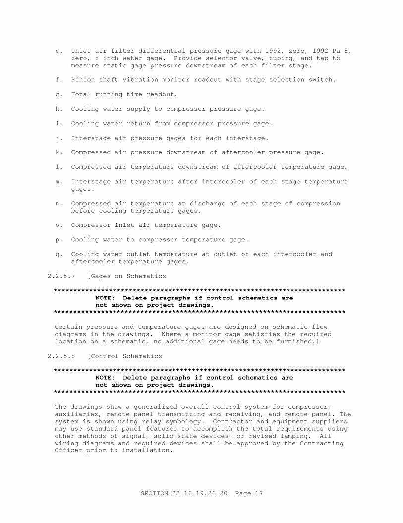
e. I nl et ai r f i l t er di f f er ent i al pr essur e gage wi t h 1992, zer o, 1992 Pa 8, zer o, 8 i nch wat er gage. Pr ovi de sel ect or val ve, t ubi ng, and t ap t o measur e st at i c gage pr essur e downst r eam of each f i l t er st age.
f . Pi ni on shaf t v i br at i on moni t or r eadout wi t h st age sel ect i on swi t ch.
g. Tot al r unni ng t i me r eadout .
h. Cool i ng wat er suppl y t o compr essor pr essur e gage.
i . Cool i ng wat er r et ur n f r om compr essor pr essur e gage.
j . I nt er st age ai r pr essur e gages f or each i nt er st age.
k. Compr essed ai r pr essur e downst r eam of af t er cool er pr essur e gage.
l . Compr essed ai r t emper at ur e downst r eam of af t er cool er t emper at ur e gage.
m. I nt er st age ai r t emper at ur e af t er i nt er cool er of each st age t emper at ur e gages.
n. Compr essed ai r t emper at ur e at di schar ge of each st age of compr essi on bef or e cool i ng t emper at ur e gages.
o. Compr essor i nl et ai r t emper at ur e gage.
p. Cool i ng wat er t o compr essor t emper at ur e gage.
q. Cool i ng wat er out l et t emper at ur e at out l et of each i nt er cool er and af t er cool er t emper at ur e gages.
2. 2. 5. 7 [ Gages on Schemat i cs
**************************************************************************NOTE: Del et e par agr aphs i f cont r ol schemat i cs ar e not shown on pr oj ect dr awi ngs.
**************************************************************************
Cer t ai n pr essur e and t emper at ur e gages ar e desi gned on schemat i c f l ow di agr ams i n t he dr awi ngs. Wher e a moni t or gage sat i sf i es t he r equi r ed l ocat i on on a schemat i c, no addi t i onal gage needs t o be f ur ni shed. ]
2. 2. 5. 8 [ Cont r ol Schemat i cs
**************************************************************************NOTE: Del et e par agr aphs i f cont r ol schemat i cs ar e not shown on pr oj ect dr awi ngs.
**************************************************************************
The dr awi ngs show a gener al i zed over al l cont r ol syst em f or compr essor , auxi l i ar i es, r emot e panel t r ansmi t t i ng and r ecei v i ng, and r emot e panel . The syst em i s shown usi ng r el ay symbol ogy. Cont r act or and equi pment suppl i er s may use st andar d panel f eat ur es t o accompl i sh t he t ot al r equi r ement s usi ng ot her met hods of s i gnal , sol i d st at e devi ces, or r evi sed l ampi ng. Al l wi r i ng di agr ams and r equi r ed devi ces shal l be appr oved by t he Cont r act i ng Of f i cer pr i or t o i nst al l at i on.
SECTI ON 22 16 19. 26 20 Page 17

] 2. 2. 6 Cont r ol Ai r Suppl y
**************************************************************************NOTE: Revi se par agr aph and make pr ovi s i ons f or cont r ol ai r i f t her e i s no exi st i ng ai r suppl y. Speci f y quant i t y of cont r ol ai r and maxi mum dew point.
**************************************************************************
[ Ext end exi st i ng] [ Pr ovi de new] cont r ol ai r syst em of dr y and pur i f i ed ai r f or t he compr essor cont r ol s. Si z i ng shal l be based on not l ess t han [ _____] [ 425 L/ s] [ 15 SCFM] . Fi l t r at i on shal l be t o 5 mi cr omet er s mi ni mum and t he ai r f r om t he dr yer shal l have a maxi mum syst em pr essur e dew poi nt [ 4] [ mi nus 18] degr ees C [ 40] [ 0] degr ees F. [ The Cont r act or shal l obt ai n syst em ai r f or t he cont r ol s by pi pi ng f r om t he exi st i ng syst em. ]
2. 2. 7 Compr essor Desi gn Feat ur es
Compr essor shal l be mul t i s t age cent r i f ugal , wi t h a mi ni mum of 2 cent r i f ugal compr essi on st ages, desi gned f or opt i mum f l ow and speed r equi r ement s t o pr oduce hi ghest space ef f i c i enci es at l owest compr essi on r at i o and t emper at ur e and l owest ext er nal noi se l evel . Speci al at t ent i on shal l be gi ven t o ener gy savi ng f eat ur es i n desi gn and ar r angement such as r adi al damper i nt ake val ve, l ong r adi us i nt er st age pi pi ng, and l ow ai r vel oci t i es. Equi pment shal l be desi gned f or economi cal and r api d mai nt enance. Casi ng component s bear i ng housi ngs and ot her maj or par t s shal l be shoul der ed, dowel l ed, or desi gned wi t h ot her pr ovi s i ons t o f ac i l i t at e accur at e al i gnment or r eassembl y. Shaf t seal s and bear i ngs shal l be accessi bl e f or i nspect i on or r epl acement wi t h a mi ni mum of di sassembl y.
2. 2. 7. 1 Casings
Casi ng shal l be cast i r on, duct i l e i r on, or cast s t eel . Casi ng st r esses shal l be wi t hi n t he l i mi t s al l owed by ASME BPVC SEC VI I I D1. Casi ngs, suppor t s, and basepl at es shal l be desi gned and f abr i cat ed t o pr ecl ude excessi ve and i nj ur i ous di st or t i on f r om t emper at ur es, pr essur es, and f or ces encount er ed i n ser vi ce condi t i ons, i ncl udi ng sur ge. Pr ovi de j ackscr ews, l i f t i ng l ugs, eyebol t s, gui de dowel s, and casi ng al i gnment dowel s t o f aci l i t at e di sassembl y and r eassembl y. When usi ng j ackscr ews f or par t i ng cont act i ng f aces, r el i eve one of t he f aces by count er bor i ng or r ecessi ng t o pr event mar r i ng t he f ace, whi ch r esul t i n l eaki ng or i mpr oper f i t . Pr ovi de l i f t i ng l ugs or eyebol t s f or r emovabl e por t i ons of t he casi ngs. Fl anged casi ng connect i ons shal l conf or m t o ASME B16. 1 or ASME B16. 5. Thr eaded connect i ons shal l conf or m t o ASME B1. 20. 1. Casi ng shal l be spl i t i n a manner per mi t t i ng di r ect access t o i mpel l er s, shaf t s, and bear i ngs. Compr essor s shal l be axi al f l ow i nl et . Gear cases shal l be encl osed, accessi bl e, f or ce l ubr i cat ed and desi gned wi t h seal s and sl i nger s t o keep oi l out of ai r syst em.
2. 2. 7. 2 Shafts
Shaf t s shal l be of f or ged or r ol l ed al l oy st eel and shal l have a machi ned f i ni sh t hr oughout t hei r ent i r e l engt h. Al l r ot at i ng component s shal l be posi t i vel y secur ed t o shaf t s by appr oved mechani cal means or i nt er f er ence shr i nk f i t s .
2. 2. 7. 3 Impellers
I mpel l er s shal l be of 400 ser i es or 17- 4 PH st ai nl ess st eel , open or c l osed
SECTI ON 22 16 19. 26 20 Page 18

desi gn, wi t h backwar d l eani ng vanes, and of wel ded, mi l l ed, or cast construction.
2. 2. 7. 4 Gears
Gear s shal l be of al l oy st eel , ANSI / AGMA 2009 and AGMA 2011 Qual i t y Number 12 or bet t er f or bot h bul l and pi ni on gear s. Gear s shal l be har dened t o 275 Br i nel l f or bul l gear and 320 Br i nel l f or pi ni on, unl ess ot her wi se appr oved. Gear s shal l be gr ound t o t he r equi r ed cont our s, checked f or pr oper cont act dur i ng assembl y at t he f act or y, and shal l not r equi r e a br eak- i n per i od i n t he f i el d f or pr oper oper at i on. Al l gear s shal l be pr essur e l ubr i cat ed.
2. 2. 7. 5 Seals
Separ at e ai r and oi l shaf t seal s shal l be pr ovi ded t o conf i ne ai r i n t he casi ng and pr event cont ami nat i on of t he ai r st r eam by l ubr i cat i ng oi l . Shaf t s seal s shal l be l abyr i nt h t ype, car bon r i ng t ype, or a combi nat i on of t he t wo t ypes. Pr ovi de an ai r space vent ed t o t he at mospher e bet ween t he ai r and oi l seal s. Seal s shal l be sui t abl e f or al l oper at i ng condi t i ons i ncl udi ng suct i on t hr ot t l i ng, st ar t - up, shut down, and moment ar y sur ge.
2. 2. 7. 6 Thr ust Bear i ngs
Axi al i mpel l er t hr ust s shal l be absor bed by t hr ust bear i ngs on t he pi ni on or t r ansf er r ed t o t he bul l gear shaf t by coni cal r i der - r i ng t hr ust col l ar s. Pi ni on t hr ust bear i ngs shal l be hydr odynami c ( f l ui d f i l m) , mul t i pl e- segment t ype, ent i t l ed pad t ype, or ot her appr oved t ype, and shal l be adequat e t o accommodat e al l oper at i ng condi t i ons, i ncl udi ng sur gi ng or st onewal l oper at i on. Bul l gear t hr ust bear i ngs shal l be s i zed f or equal t hr ust i n bot h di r ect i ons and shal l be adequat e f or any axi al l oads t r ansmi t t ed t hr ough t he dr i ver coupl i ng.
2. 2. 7. 7 Radi al Bear i ngs
Radi al bear i ngs shal l be hydr odynami c ( f l ui d f i l m) , pr eci s i on bor ed s l eeve or pad t ype, desi gned f or easy r epl acement by a spl i t desi gn or axi al l y r emovabl e ar r angement . Hi gh speed pi ni on bear i ngs shal l be ant i - oi l whi p, t i l t i ng pad, t i l t ed pad, or ot her appr oved t ype. Bear i ng desi gn shal l pr ovi de l ow vi br at i on and suf f i c i ent dampi ng at r at ed speed and al l oper at i ng modes, i ncl udi ng r at ed capaci t y and unl oadi ng down t o 15 t o 20 per cent of unl oaded power .
2. 2. 7. 8 I nt er cool er , Af t er cool er s, and Oi l Cool er s
I nt er cool er s, af t er cool er , and oi l cool er shal l i ncl ude admi r al t y br ass [ or copper ] t ubes conf or mi ng t o ASTM B111/ B111M i n admi r al t y t ube sheet s conf or mi ng t oASTM B171/ B171M wi t h pl at e f i ns and baf f l es f or opt i mum cool i ng and f oul i ng r esi st ance usi ng [ f r esh] [ _____] wat er . Pr ovi de an i nt er cool er bet ween st ages of compr essi on f act or y assembl ed on uni t base wi t h pi pi ng. The af t er cool er may be mount ed separ at el y. I nt er cool er s, af t er cool er , and oi l cool er shal l be f act or y t est ed at 1. 5 t i mes oper at i ng pr essur e. Ext er nal i nt er cool er s and af t er cool er shal l be const r uct ed i n accor dance wi t h ASME BPVC SEC VI I I D1, r equi r ement s and be ASME code st amped f or 1207 kPa ( gage) 175 psi g wor ki ng pr essur e. I nt er cool er s and af t er cool er shal l be capabl e of one pi ece bundl e r emoval . Each i nt er cool er shal l be equi pped wi t h an i nt egr al or di r ect connect ed moi st ur e separ at or wi t h condensat e t r ap or aut omat i c dr ai ner val ve assembl y. Pi pi ng t o dr ai ner and dr ai ner assembl e shal l be Cl ass 300 st ai nl ess st eel . Desi gn
SECTI ON 22 16 19. 26 20 Page 19

i nt er cool er s and af t er cool er f or 11 and 8 degr ees C 20 and 15 degr ees F appr oach, r espect i vel y, and a f oul i ng f act or of 0. 001 f or bot h s i des of exchanger ; however , t he appr oach t emper at ur e used t o s i ze t he cool er s shal l be r educed i f r equi r ed t o meet af t er cool er maxi mum ai r out l et t emper at ur e speci f i ed. Nonst andar d cool er s shal l be pr ovi ded i f r equi r ed t o meet t he af t er cool er maxi mum ai r out l et t emper at ur e r equi r ement . Al l cool er s shal l be of count er - f l ow desi gn.
2. 2. 7. 9 Lubr i cat i on Syst em
I ncl ude r eser voi r , shaf t dr i ven posi t i ve di spl acement pump, t wi n oi l cool er s, t wi n f i l t er / st r ai ner ( r eadi l y r epl aceabl e car t r i dges whi l e oper at i ng) and par al l el pi pi ng and val v i ng pr ovi s i ons t o accommodat e a separ at el y dr i ven pr el ube l ubr i cat i on oi l pump f or st ar t - up and st andby. Syst em shal l be f act or y assembl ed and t est ed. The oi l r eser voi r shal l r et ai n a mi ni mum 3- mi nut e oi l suppl y. Lubr i cat i ng oi l shal l conf or m t o MIL-PRF-17331 , Lubr i cant No. 2190- TEP or as r ecommended by compr essor manuf act ur er . Oi l cool er shal l be desi gned f or a f oul i ng f act or of 0. 001 f or bot h s i des of exchanger . Pr essur e l ubr i cat e hydr odynami c bear i ngs. Pr ovi de t he oi l sump wi t h l evel i ndi cat or and dr ai n and f i l l connect i ons.
a. Pr el ubr i cat i on pump shal l be s i zed by ai r compr essor manuf act ur er f or t he r equi r ement s of t he syst em, but shal l meet t he f ol l owi ng r equi r ement s. Pump shal l be posi t i ve di spl acement gear pump separ at el y mount ed wi t h mot or on a common base pl at e wi t h dr i p l i p and dr ai n.
( 1) Per f or mance: Pump shal l have separ at e saf et y val ve bypass set at [ _____] [ 172 kPa] [ 25 psi ] above peak expect ed pr essur e.
( 2) Mat er i al s shal l be har dened st eel gear s and shaf t , cast i r on case, br onze bear i ngs, mechani cal seal .
( 3) Fl exi bl e coupl i ng wi t h shaf t guar d shal l be pr ovi ded, except t hat t hese i t ems ar e not r equi r ed f or a c l ose- coupl ed pump.
( 4) Mot or shal l be NEMA MG 1, Desi gn A, Cl ass B i nsul at i on, of open dr i p- pr oof t ype. Fur ni sh combi nat i on t ype st ar t er f or mot or .
b. Lube Oi l Heat er : Pr ovi de t her most at i cal l y cont r ol l ed el ect r i c heat er i n l ubr i cat i on oi l sump of suf f i c i ent capaci t y t o heat up and mai nt ai n manuf act ur er ' s r ecommended oi l t emper at ur e when uni t i s col d at [ _____] [ 0 degr ees C] [ 32 degr ees F] ambi ent . Pr ovi de l ow oi l l evel i ndi cat or wi t h l i ght f or pr ot ect i on of heat er .
2. 2. 8 El ect r i c Mot or s
**************************************************************************NOTE: Pol yphase mot or s shal l be sel ect ed based on r equi r ement s of t he dr i ven equi pment , ser vi ce condi t i ons, mot or power f act or , l i f e cycl e cost , and hi gh ef f i c i ency i n accor dance wi t h NEMA MG 10.
Use Mot or Mast er sof t war e pr ogr am t o i dent i f y t he most ef f i c i ent and cost ef f ect i ve pol yphase mot or f or a speci f i c appl i cat i on. Mot or Mast er i s l ocat ed i n t he " TOOLS" sect i on of Const r uct i on Cr i t er i a Base ( CCB) . For addi t i onal gui dance cont act Char l i e Mandevi l l e of t he NAVFAC Cr i t er i a Of f i ce at ( 757) 322- 4208. Anot her sour ce of i nf or mat i on on ener gy
SECTI ON 22 16 19. 26 20 Page 20

ef f i c i ency i s E- sour ce, accessi bl e t o Navy user s on t he Naval Faci l i t i es Engi neer i ng Cent er ( NFESC) home page http://energy.navy.mil/ .
**************************************************************************
Ef f i c i ency and l osses shal l be det er mi ned i n accor dance wi t h I EEE 112. Unl ess ot her wi se speci f i ed hor i zont al pol yphase squi r r el cage mot or s r at ed one t o 125 hor sepower shal l be t est ed by dynamomet er Met hod B as descr i bed i n Sect i on 6. 4 of I EEE 112. Mot or ef f i c i ency shal l be cal cul at ed usi ng For m B of I EEE 112 cal cul at i on pr ocedur e.
Pol yphase mot or s l ar ger t hat 125 hor sepower shal l be t est ed i n accor dance with I EEE 112 wi t h st r ay l oad l oss det er mi ned by di r ect measur ement or i ndi r ect measur ement ( t est l oss mi nus convent i onal l oss) .
The ef f i c i ency shal l be i dent i f i ed on t he mot or namepl at e by t he capt i on NEMA Nomi nal ef f i c i ency or NEMA Nom ef f .
2. 2. 8. 1 Mai n El ect r i c Dr i ve Mot or
**************************************************************************NOTE: Cent r i f ugal compr essor s ar e nor mal l y pr ovi ded wi t h 3600 r pm i nduct i on mot or s. The speci f i cat i on wi l l be consi der ed r est r i c t i ve by manuf act ur er s i f an 1800 r pm synchr onous mot or i s speci f i ed because a speci al speed i ncr easi ng gear box wi l l make t hem noncompet i t i ve wi t h nonl ubr i cat ed r ot ar y compr essor s.
**************************************************************************
The mai n dr i ve mot or f or each compr essor shal l be an i nduct i on mot or , [ _____] kW hor sepower , wi t h a cont i nuous ser vi ce f act or of 1. 0. Si ze t he mot or so t hat t he namepl at e kW hor sepower r at i ng i s not exceeded under t he ent i r e r ange of oper at i ng condi t i ons speci f i ed. Mot or shal l be hi gh ef f i c i ency t ype, r at ed not l ess t han 95 per cent based on I EEE 112 t est i ng and l abel i ng. El ect r i cal ser vi ce wi l l be as speci f i ed. Mot or shal l be desi gned f or r educed vol t age st ar t i ng [ at [ 50] [ 65] [ 80] per cent of f ul l vol t age] , al l owi ng f or char act er i st i cs of t he connect ed l oad, and shal l s t ar t wi t hout under vol t age t r i ppi ng. Pr ovi de r esi st ance t emper at ur e det ect or s ( RTD) at t ached t o or i mbedded i n mot or wi ndi ng f or cont r ol syst em. The mot or shal l meet t he r equi r ement s of NEMA MG 1 wi t h Cl ass F i nsul at i on. Mot or desi gn shal l i ncl ude acoust i cal cover i ng and r educed noi se ai r i nt ake housi ng and be r at ed f or 84 dBA or l ess at 0. 9 m 3 f eet under f ul l l oad. Pr ovi de space heat er s f or pr ot ect i on of wi ndi ngs dur i ng mot or shut downs.
2. 2. 8. 2 Accessor y and Rel at ed Equi pment Mot or s
Mot or s l ess t han 3/ 8 kW 1/ 2 hor sepower shal l be s i ngl e- phase i nduct i on mot or s and shal l conf or m t o NEMA MG 1. Mot or s 3/ 8 t hr ough 3. 75 kW 1/ 2 t hr ough 5 hor sepower shal l be t hr ee- phase i nduct i on mot or s and shal l conf or m t o NEMA MG 1. Si ngl e- phase and t hr ee- phase mot or s shal l have bi met al l i c di sk t her most at s at t ached t o or i mbedded i n t he mot or wi ndi ng. Mot or s shal l have NEMA MG 1 Cl ass B i nsul at i on.
2. 2. 9 Cont r ol Panel
Cont r ol uni t panel conf or mi ng t o NEMA I CS 6, package or f r ame mount ed, f act or y desi gned, assembl ed, and mount ed shal l be pr ovi ded compl et e wi t h
SECTI ON 22 16 19. 26 20 Page 21

connect i ons made t o sensi ng poi nt s. The panel shal l be f abr i cat ed of f or med st r et cher l evel ed sheet st eel , r ei nf or ced, and assembl ed i nt o a r i gi d uni t . Gasket ed access door s shal l be pr ovi ded as r equi r ed. Panel shal l be f act or y f i ni sh pai nt ed. The panel shal l meet NEMA 12 r equi r ement s.
a. Panel shal l cont ai n el ect r i c and saf et y cont r ol wor k r equi r ed, i ncl udi ng ei t her al ar m annunci at or or i ndi v i dual l abel ed pi l ot l i ght s ar r anged i n a gr oup. Panel shal l cont ai n al ar m devi ce wi t h l i ght and si l enci ng. Gener al i zed ar r angement i n accor dance wi t h dr awi ngs.
b. Panel shal l cont ai n st ar t and st op but t ons ( t he l at t er wi t h l ockout f eat ur e) , v i br at i on moni t or subpanel , di schar ge ai r pr essur e gage, cont r ol t est swi t ch and l i ght s, r eset but t on, gr een uni t r unni ng l i ght , and cont r ol sel ect or swi t ch.
c. Oi l pr essur e gages shal l be mount ed separ at el y f r om panel .
2. 2. 10 Accessories
Requi r ed accessor i es i ncl ude:
2. 2. 10. 1 Cont r ol Val ves
Pneumat i cal l y cont r ol l ed val ves on suct i on i nl et of compr essor and on bl owof f bypass l i ne. Mount suct i on i nl et cont r ol val ve on uni t .
2. 2. 10. 2 Ai r I nt ake Devi ces
**************************************************************************NOTE: Change compr essor ai r i nl et descr i pt i on t o sui t pr oj ect i f r equi r ed.
**************************************************************************
Compr essor ai r i nl et shal l be pi ped t o t he out s i de of t he bui l di ng and consi st of t he f ol l owi ng:
a. I nt ake weat her hood wi t h r ai n hood and bi r d scr een. Mat er i al shal l be gal vani zed st eel or al umi num al l oy, mi ni mum 20 gage.
b. I nt ake pi pe, ASTM A36/ A36M st eel gal vani zed, 12 gage or Schedul e 5 mi ni mum, f r om i nt ake weat her hood t o f i l t er housi ng f l ange, wel ded construction.
c. Fi l t er housi ng by f i l t er manuf act ur er t o i ncl ude f i l t er f r ames, access door ( s) . Mat er i al f or housi ng shal l be 1. 65 mm 0. 065 i nch t hi ckness, Cl ass 5000 al umi num al l oy. Uni t shal l be r i gi d and f r ee f r om di st r ess wi t h al l seams seal ed.
d. I nt ake Pi pe f r om Fi l t er Encl osur e t o Compr essor : Al umi num al l oy ASTM B209M ASTM B209, Al c l ad al l oy 5052- H32 or equi val ent , mi ni mum 10 gage, f l anged, wel ded wi t h 5XXX wel di ng r od usi ng TI G met hod and i ncl udi ng expansi on bel l ows.
2. 2. 10. 3 Compr essor Ai r Out l et Connect i ons
Compr essor ai r out l et f l exi bl e connect i on of st ai nl ess st eel bel l ows wi t h br ai ded st eel cover j acket , wi t h st ai nl ess st eel l i ner s l eeve, 460 mm 18 i nch nomi nal l engt h bel l ows, f l anged ends, Cl ass 150. I f ai r bypass connect s separ at el y t o t he compr essor f r om t he out l et l i ne, pr ovi de a
SECTI ON 22 16 19. 26 20 Page 22

second f l exi bl e connect i on of st ai nl ess st eel bel l ows wi t h br ai ded j acket f or t he bypass.
2. 2. 11 I nl et Ai r Fi l t er s
Pr ovi de a t hr ee- st age f i l t er syst em, compl et e wi t h mount i ng r acks ( hor i zont al f l ow) , i nt er st age seal s, and r epl aceabl e f i l t er s. Fi l t er uni t shal l be pr ovi ded compl et e i ncl udi ng encl osur e or housi ng, and f r ames. Encl osur e shal l be Cl ass 5000 al umi num al l oy wi t h i nl et and out l et f l anges. Const r uct i on shal l be wel ded or , wher e wel di ng i s not pr act i cal , c l ose r i vet ed and caul ked, weat her t i ght , wi t h access door s f or f i l t er r epl acement and cl eani ng. Access door s shal l be r ei nf or ced, f ul l y gasket ed wi t h cont i nuous f l exi bl e neopr ene gasket s, cor r osi on- r esi st ant cont i nuous hi nges and quar t er - t ur n l at ches t o ensur e t i ght ness. Al l i nt er nal f er r ous sur f aces, i ncl udi ng gal vani zed, shal l r ecei ve a f act or y- appl i ed epoxy pr i me and f i ni sh coat f or cor r osi on r esi st ance. Fi l t er s shal l consi st of t hr ee separ at e st ages and si zed t o f i t t he avai l abl e space.
2. 2. 11. 1 First-Stage
Fi r st - st age f i l t er shal l be f l at , 50 mm 2 i nch t hi ckness, r epl aceabl e medi a, and r at ed f or t he r equi r ed ai r quant i t y at 2. 54 m/ s 500 FPM nomi nal f ace vel oci t y, f r i c t i on c l ean 62 Pa 0. 25 i nch wat er gage, ef f i c i ency 98 per cent of 15 mi cr omet er s 0. 60 mi cr oi nches and 90 per cent of 5 mi cr omet er s 0. 20 mi cr oi nches.
2. 2. 11. 2 Second-Stage
Second- st age f i l t er shal l be deep pl eat ed t ype, 229 mm 9 i nchesnomi nal dept h and r at ed f or t he r equi r ed ai r quant i t y at 1. 78 m/ s 350 FPM nomi nal f ace vel oci t y, f r i c t i on c l ean 50 Pa 0. 20 i nch wat er gage, ef f i c i ency 98 per cent t o 5 mi cr omet er s 0. 20 mi cr oi nches and 90 per cent t o 3 mi cr omet er s 0. 12 mi cr oi nches.
2. 2. 11. 3 Third-Stage
Thi r d- st age f i l t er shal l be deep pl eat ed t ype 305 mm 12 i nchesmi ni mum dept h and r at ed f or t he r equi r ed ai r quant i t y at 1. 78 m/ s 350 FPM nomi nal f ace vel oci t y, f r i c t i on c l ean 75 Pa 0. 30 i nch wat er gage, ef f i c i ency 99. 9 per cent t o 0. 5 mi cr omet er 0. 02 mi cr oi nches.
2. 2. 11. 4 Fi l t er Medi a
Fi l t er medi a shal l be r at ed and l i s t ed UL Cl ass 2. Fi l t er ef f i c i enci es shal l be based on Nat i onal Bur eau of St ands ( NBS) t ype di scol or at i on gr avi met r i c t est met hod usi ng at mospher i c dust .
2. 2. 12 Bypass Li ne Si l encer
Pr ovi de a bypass l i ne s i l encer wi t h each compr essor as sel ect ed by compr essor manuf act ur er f or suf f i c i ent noi se at t enuat i on t o meet sound l evel cr i t er i a not gr eat er t han 84 dBA measur ed at an el evat i on of 1. 50 met er s 5 f eet , and 3 met er s 10 f eet hor i zont al l y f r om si l encer .
2. 2. 13 I sol at i ng Pad
I f speci f i cal l y r ecommended by t he compr essor manuf act ur er , each compr essor st eel f r ame shal l be mount ed on a neopr ene waf f l e or r i b t ype i sol at or pad whi ch ext ends uni f or ml y and cont i nuousl y al ong t he base mount i ng sur f ace.
SECTI ON 22 16 19. 26 20 Page 23

The neopr ene mat er i al shal l be of br i dge bear i ng pad qual i t y neopr ene and shal l be f or mul at ed f or 40 dur omet er har dness. The maxi mum bear i ng pr essur e on t he i sol at i ng pad shal l be 345 kPa 50 psi . The pads shal l be composed of t wo l ayer s or 8 mm 5/ 16 i nch neopr ene bonded t o and sandwi chi ng 16 gage gal vani zed st eel . Compr essor bol t down t hr ough t he pad shal l be accompl i shed usi ng 6 mm 1/ 4 i nch t hi ck neopr ene i mpr egnat ed duck washer s. Neopr ene bushi ngs ar e not accept abl e.
2. 3 AI R FLOW RATE AND PRESSURE RECORDER AND MEASUREMENT
Pr ovi de a compl et e f l ow and pr essur e measur ement and r ecor di ng package. Pr ovi de or i f i ce f l anges wi t h pr essur e t aps, squar e edged st ai nl ess st eel paddl e or i f i ce pl at e. The or i f i ce pl at e shal l be concent r i c t ype, of 3 mm 0. 125 i nch t hi ckness and shal l meet ASME St andar ds. Or i f i ce shal l be s i zed f or 10 kPa 40 i nch wat er col umn di f f er ent i al at a f ul l scal e f l ow r at e of [ _____] L/ s SCFM at compr essor based on 827 kPa ( gage) 120 psi g upst r eam pr essur e. St at i c gage pr essur e measur ement devi ce of t he r ecor der shal l have a r ange of zer o t o 1379 kPa ( gage) 200 psi g. Pr ovi de copper i nt er connect i ng t ubi ng bet ween t he pr essur e t aps and t he r ecor der as par t of t hi s measur ement and r ecor di ng package. Pr ovi de a t wo- pen r ecor der f or t he measur ement st at i on. Pens shal l r ecor d pr essur e ( 0 t o 1379 kPa ( gage) 200 psi g r ange) and ai r f l ow ( 0 t o [ _____] L/ s SCFM) . Recor der shal l be el ect r i c dr i ve and housed i n dust - t i ght st eel cabi net . Char t s shal l be 305 mm 12 i nch di amet er wi t h evenl y di v i ded gr aduat i ons. Dr i ve shal l be 7 day c i r c l e. Pr ovi de cont i nuous f l ow i nt egr at i on of a 7 di gi t count er t ype. Pens shal l be suppl i ed wi t h l ong- l i f e car t r i dges and capi l l ar y suppl y. Char t case shal l be i nt er nal l y i l l umi nat ed. Access t o char t s shal l be t hr ough f r ont access wi ndow door . Cal i br at ed over al l accur acy of t he r ecor ded measur ement s shal l be wi t hi n pl us or mi nus 1. 0 per cent of f ul l scal e. Fur ni sh a suppl y of 400 char t s wi t h t he r ecor der .
2. 4 CARBON MONOXI DE MONI TOR
**************************************************************************NOTE: I ncl ude car bon monoxi de moni t or i n syst ems whi ch ar e used f or br eat hi ng ai r per DM 3. 5, Sect i on 3.
**************************************************************************
The car bon monoxi de ( CO) moni t or uni t shal l be of t he pr essur e t ype wi t h at t ached sampl i ng syst em. The uni t shal l be sol i d st at e t ype oper at i on, 2 t o 50 ppm r ange, CO i ndi cat i ng, wi t h pr ovi s i ons f or mi l l i amp si gnal t o r emot e r ecor der , adj ust abl e set poi nt , and nor mal l y open/ nor mal l y c l osed cont act s f or r emot e s i gnal . Power shal l be 120 vol t , s i ngl e phase, 60 her t z wi t h power cor d and pl ug. Response t i me nor mal l y 2 mi nut es per sampl e/ pur ge. Uni t shal l be mount ed i n a gasket ed encl osur e wi t h f ace gage i ndi cat i on CO r eadi ngs.
2. 4. 1 Sampl i ng Syst em
Sampl i ng syst em shal l i ncl ude shut of f val ve f i l t er / r egul at or , pr essur e gage, manual dr ai ner , and l i ne humi di f i er set at 50 per cent . Dr aw sampl e f r om compr essor di schar ge.
2. 4. 2 Test Syst em
Test syst em shal l i ncl ude cal i br at i on gas ( 20 ppm CO) cyl i nder t est gas ( 200 ppm CO) cyl i nder , and cal i br at i on connect or s wi t h qui ck di sconnect .
SECTI ON 22 16 19. 26 20 Page 24

2. 5 SOURCE QUALI TY CONTROL
2. 5. 1 Fact or y Test Pr ocedur es
The compl et el y assembl ed ai r compr essor package, i ncl udi ng t he act ual cont r act dr i ve mot or , i nt er cool er s, l ubr i cat i on syst em, and cont r ol panel shal l be subj ect ed t o per f or mance t est s, bal ance t est s, and sound l evel and r un- i n t est s. Uni t shal l compl y wi t h guar ant ee r equi r ement s appl y i ng engi neer i ng adj ust ment s t o guar ant ee condi t i ons. Test shal l be cer t i f i ed by t he manuf act ur er . Test shal l be r un on t he manuf act ur er ' s t est st and usi ng dr i ver f or t hi s cont r act . Test s shal l be i n accor dance wi t h ASME PTC 10 f or mat . Ful l - r ange per f or mance t est s shal l i ndi cat e per f or mance at maxi mum r at ed f l ow, r at i ng poi nt , and bl owof f condi t i ons. Al l accessor y per f or mance condi t i ons shal l be r epor t ed, i ncl udi ng i nt er cool er s, af t er cool er s, and l ubr i cat i on and cont r ol syst ems. The compl et e uni t shal l be f act or y t est ed wi t h sound met er s i n accor dance wi t h I SO 2151. Locat i on shal l be one hor i zont al met er f r om uni t at 1. 5 met er s above t he f l oor . Test shal l i ncl ude r eadi ngs at each oct ave band mi dpoi nt and t he " A" scal e, and shal l be 84 dBA or l ess and 90 deci bel s at any oct ave band. Resul t s of t est shal l be i ncl uded i n t he f act or y t est r epor t on t he I SO 2151 f or mat . Fact or y t est dat a may be cor r ect ed t o t he l evel s of an equi val ent backgr ound noi se l evel of 60 dBA showi ng cal cul at i ons f or r ef er ence use.
2. 5. 2 Super vi s i on of Test i ng
Syst em and component s t est i ng shal l be conduct ed or super vi sed by ei t her a desi gnat ed aut hor i zed and f act or y t r ai ned r epr esent at i ve of t he compr essor manuf act ur er suppl y i ng t he uni t or a r egi st er ed Mechani cal Engi neer exper i enced i n such wor k.
2. 5. 3 Syst em Test
Test i ng of syst em shal l conf or m t o r equi r ement s out l i ned and shal l be wi t nessed by t he Cont r act i ng Of f i cer .
2. 5. 4 Appr oval of Test i ng Pr ocedur e
Pr oposed t est i ng pr ocedur e shal l be appr oved by t he Cont r act i ng Of f i cer and t he i ndi v i dual i n char ge of t est i ng pr i or t o conduct i ng t est s.
2. 5. 5 Cer t i f i cat i on of Per f or mance Test s
The t est super vi sor shal l cer t i f y per f or mance by t est t o be i n compl i ance wi t h speci f i cat i ons.
PART 3 EXECUTI ON
3. 1 INSTALLATION
The Cont r act or shal l i nst al l t he ai r compr essor s and accessor i es i n accor dance wi t h manuf act ur er ' s r ecommendat i ons and as i ndi cat ed on t he dr awi ngs. Al l equi pment shal l be i nst al l ed pl umb and l evel and anchor ed t o st r uct ur e, mat chi ng hol es pr ovi ded.
3. 1. 1 Manuf act ur er ' s Super vi s i on
I nst al l t he compr essor s under t he di r ect super vi s i on of an aut hor i zed r epr esent at i ve of t he manuf act ur er .
SECTI ON 22 16 19. 26 20 Page 25

3. 2 GENERAL REQUI REMENTS FOR I NSTALLI NG AI R COMPRESSORS
**************************************************************************NOTE: Del et e or modi f y r equi r ement s on exi st i ng bui l di ng and wei ght handl i ng equi pment t o sui t t he project.
**************************************************************************
Ai r compr essor s wi t h cont r act mot or and accessor i es shal l be f act or y assembl ed, r un i n, and t est ed compl et e bef or e shi pment t o j ob s i t e. [ The Cont r act or i s advi sed t hat t her e ar e l i mi t at i ons t o door openi ng s i zes and avai l abl e cr ane l i f t i ng capaci t y. Cr ane uni t i s speci f i ed t o per mi t s i ngl e l i f t s of compl et e compr essor under speci al appr oval onl y. ] Shoul d t he uni t r equi r e di sassembl y f or i nst al l at i on, r eassembl y shal l be under t he di r ect super vi s i on of t he compr essor manuf act ur er ' s aut hor i zed r epr esent at i ve. Compl et e uni t shal l be mount ed on a r i gi d s i ngl e or equi val ent mechani cal l y j oi ned st eel or i r on base. Submi t i nst al l at i on sequence pl ans t o t he Cont r act i ng Of f i cer f or appr oval pr i or t o i nst al l at i on. [ Any bui l di ng mat er i al s r emoved t o accompl i sh i nst al l at i on shal l be r ei nst al l ed i f undamaged by r emoval pr ocedur es; or i f damaged, shal l be r epl aced wi t h new mat er i al s t o mat ch or i gi nal conf i gur at i on. ]
3. 2. 1 Pr ompt I nst al l at i on
The Cont r act or i s advi sed t hat any compr essor r ecei ved shal l be i nst al l ed and pl aced i n oper at i on pr ompt l y t o pr event t i me det er i or at i on when not i nst al l ed. Shoul d t he Cont r act or sust ai n a del ay exceedi ng 90 days pr i or t o act ual i nst al l at i on, t he Cont r act i ng Of f i cer shal l have t he opt i on of r equi r i ng br eakdown and r eassembl y t o i nspect and cl ean pr i or t o pl aci ng i n oper at i on. Thi s wor k shal l be at no addi t i onal cost t o t he Gover nment .
3. 2. 2 St ar t - Up Ser vi ces
The Cont r act or shal l f ur ni sh t he ser vi ces of a compr essor manuf act ur er ' s aut hor i zed r epr esent at i ve t o super vi se pr est ar t checkout , i ni t i al s t ar t - up, per f or mance t est i ng, and oper at or i nst r uct i on. Ti me avai l abl e shal l be as r equi r ed t o pr oper l y st ar t up but not l ess t han 3 consecut i ve days f or t he compressor.
3. 3 FI ELD QUALI TY CONTROL
3. 3. 1 Fi el d Test Pr ocedur es
Compl et e f i el d per f or mance t est i ng of t he t ot al syst em shal l be per f or med by t he Cont r act or and wi t nessed by t he Cont r act i ng Of f i cer . Ai r compr essor syst em t est s shal l be conduct ed by ei t her a compr essor manuf act ur er ' s f act or y t r ai ned and aut hor i zed r epr esent at i ve appr oved by t he Cont r act i ng Of f i cer or a qual i f i ed r egi st er ed Mechani cal Engi neer . Test s may be r un on i ndi v i dual component s or on t he syst em as a whol e at Cont r act or opt i on. Fi el d t est s r equi r e use of t he act ual compr essor dr i ve mot or . Test shal l i ncl ude oper at i on at r at ed capaci t y f or not l ess t han 4 hour s.
3. 3. 1. 1 Ai r Compr essor Per f or mance Test s
Compl et e per f or mance t est shal l be r un at maxi mum l oad, r at ed l oad, at poi nt of unl oad but pr i or t o unl oad, and unl oaded condi t i on. Dat a shal l be r ecor ded l i s t i ng:
SECTI ON 22 16 19. 26 20 Page 26

a. Ai r f l ow, i nl et pr essur e and t emper at ur e, humi di t y; di schar ge pr essur e and t emper at ur e.
b. I nt er cool er wat er f l ows, t emper at ur es, and pr essur es.
c. Af t er cool er wat er f l ow, t emper at ur es, and pr essur es.
d. Lube oi l cool i ng wat er f l ow, t emper at ur es, and pr essur es.
e. Lube oi l f l ow, pr essur es, and t emper at ur e.
f . Cool i ng wat er pump f l ow, pr essur es, and mot or amper age.
g. [ Cool i ng t ower ] [ Cl osed ci r cui t cool er ] ai r f l ow, wat er and ai r t emper at ur es, wat er pr essur e, and mot or amper age.
h. El ect r i cal l oad i n vol t s and amper es f or compr essor mot or , pr el ube oi l pump mot or , and compr essor auxi l i ar i es.
i . I nt ake f i l t er pr essur e di f f er ent i al ( c l ean) .
j . St ar t - up sequence, al ar m si gnal s and aut omat i c syst em shut down.
k. Cont r ol sequence, ei t her modul at i ng or t wo st ep [ i n phase wi t h t he ot her ai r compr essor s and exi st i ng pl ant ai r ] .
l . Test compr essor i nt ake and di schar ge f or conf or mance t o CGA G- 7. 1. Compr essor di schar ge shal l show no i ncr ease i n cont ami nant s.
3. 3. 1. 2 I nst r ument at i on Test
The Cont r act or may use i nst r ument at i on pr ovi ded i n t he cont r act and i nst r ument at i on pr ovi ded by t he Cont r act or t o conduct t he t est . The t est i ng pr ocedur e and i nst r ument at i on shal l be submi t t ed t o t he Cont r act i ng Of f i cer f or appr oval pr i or t o conduct i ng t est s. The f or mat of ASME PTC 10 i s r equi r ed. I t i s i nt ended t hat a f ul l f i el d t est be per f or med. However , i n l i eu of pr eci se i nst r ument at i on, t he Cont r act or may use cer t i f i ed cool i ng wat er pump cur ves [ and [ cool i ng t ower ] [ c l osed ci r cui t cool er ] f an cur ves] . Shut down si gnal s shal l be caused by t hr ot t l i ng sel ect ed f l ui ds. Test dat a, such as ai r i nt ake t emper at ur e and humi di t y, shal l be mat hemat i cal l y cor r ect ed t o per f or mance t est r equi r ement l evel s.
3. 3. 1. 3 Sound Level Test s
Sound l evel t est s shal l be conduct ed concur r ent l y. Br oad Band " A" scal e r eadi ngs and Oct ave Band r eadi ngs shal l be t aken and r ecor ded at t he same posi t i ons as on t he f act or y t est i ng. Maxi mum per mi ssi bl e l evel shal l be 84 deci bel s one hor i zont al met er f r om t he compr essor and 1. 5 met er s above t he f l oor , wi t h uni t i n oper at i on and al l ot her s i gni f i cant equi pment not r equi r ed f or t est wi t hi n t he same bui l di ng bay shut down at t he same l ocat i on pr evi ousl y descr i bed. A backgr ound noi se cor r ect i on t o 60 deci bel s i s per mi ssi bl e.
3. 3. 1. 4 Def i c i enci es Di scover ed i n Test i ng
Any oper at i onal def i c i enci es not ed i n t he t est s shal l be pr ompt l y cor r ect ed and af f ect ed por t i ons of t he t est r er un.
SECTI ON 22 16 19. 26 20 Page 27

3. 3. 1. 5 Test i ng Tol er ances
A t ol er ance of pl us 2 per cent mi nus zer o on f l ow, pl us or mi nus 4 per cent on power , or pl us or mi nus 5 per cent on any ot her var i abl e f or each i t em of equi pment or f l ui d wi t h al l ot her s conf or mi ng i s per mi ssi bl e on f i el d t est r esul t s when compar ed t o f act or y t est dat a and t o guar ant ee per f or mance dat a except t hat compr essor ai r f l ow, di schar ge pr essur e, and mot or power shal l be met .
3. 3. 2 Appr oval of Test i ng Pr ocedur e
Pr oposed t est i ng pr ocedur e shal l be appr oved by t he Cont r act i ng Of f i cer and t he i ndi v i dual i n char ge of t est i ng pr i or t o conduct i ng t est s.
3. 4 TRAI NI NG OF GOVERNMENT PERSONNEL
Dur i ng st ar t - up and f i el d t est i ng, t r ai n Gover nment st at i on per sonnel i n t he oper at i on and mai nt enance of compr essor , [ cool i ng t ower , ] [ c l osed ci r cui t cool er , ] associ at ed equi pment , and al l cont r ol and saf et y devi ces. Tr ai ni ng shal l not commence unt i l equi pment i s oper at i onal and st at i on per sonnel ar e i n at t endance. At l east one day of c l assr oom t r ai ni ng and one day of f i el d t r ai ni ng shal l be f ur ni shed f or each desi gnat ed Gover nment per sonnel . When f act or y t r ai ni ng i s r equi r ed by t he compr essor manuf act ur er f or pr oper mai nt enance and over haul of t he compr essor s, such t r ai ni ng shal l be f ur ni shed by t he compr essor manuf act ur er at no addi t i onal cost t o t he Gover nment . The Gover nment wi l l bear t he cost of t r avel and l i v i ng expenses f or Gover nment per sonnel as necessar y f or t he f act or y training.
- - End of Sect i on - -
SECTI ON 22 16 19. 26 20 Page 28