ufgs 26 12 21 single-phase pad-mounted transformers 26 12 21.pdf · section 26 12 21 single-phase...
TRANSCRIPT
**************************************************************************USACE / NAVFAC / AFCEC / NASA UFGS- 26 12 21 ( May 2017) Change 2 - 11/ 19 - - - - - - - - - - - - - - - - - - - - - - - - - - - - -Pr epar i ng Act i v i t y: NAVFAC Super sedi ng UFGS- 26 12 21 ( November 2013)
UNI FI ED FACI LI TI ES GUI DE SPECI FI CATI ONS
Ref er ences ar e i n agr eement wi t h UMRL dat ed Oct ober 2019**************************************************************************
SECTION TABLE OF CONTENTS
DIVISION 26 - ELECTRICAL
SECTION 26 12 21
SINGLE-PHASE PAD-MOUNTED TRANSFORMERS
05/17
PART 1 GENERAL
1.1 REFERENCES 1.2 RELATED REQUIREMENTS 1.3 DEFINITIONS 1.4 SUBMITTALS 1.4.1 Government Submittal Review 1.4.2 Reduced Submittal Requirements 1.5 QUALITY ASSURANCE 1.5.1 Pad-Mounted Transformer Drawings 1.5.2 Regulatory Requirements 1.5.3 Standard Products 1.5.3.1 Alternative Qualifications 1.5.3.2 Material and Equipment Manufacturing Date 1.6 MAINTENANCE 1.6.1 Additions to Operation and Maintenance Data
PART 2 PRODUCTS
2.1 PRODUCT COORDINATION 2.2 SINGLE-PHASE PAD-MOUNTED TRANSFORMERS (DEAD-FRONT) 2.2.1 Compartment Construction 2.2.1.1 High Voltage 2.2.1.2 Low Voltage 2.2.2 Transformer 2.2.2.1 Specified Transformer Efficiencies 2.3 INSULATING LIQUID 2.4 LIQUID-FILLED TRANSFORMER NAMEPLATES 2.5 CORROSION PROTECTION 2.6 WARNING SIGNS AND LABELS 2.7 GROUNDING AND BONDING 2.8 PADLOCKS 2.9 CAST-IN-PLACE CONCRETE 2.10 SOURCE QUALITY CONTROL 2.10.1 Transformer Test Schedule
SECTION 26 12 21 Page 1
2.10.2 Test Instrument Calibration 2.10.3 Design Tests 2.10.4 Routine and Other Tests
PART 3 EXECUTION
3.1 INSTALLATION 3.2 GROUNDING 3.2.1 Grounding Electrodes 3.2.2 Pad-Mounted Transformer Grounding 3.2.3 Connections 3.2.4 Grounding and Bonding Equipment 3.3 INSTALLATION OF EQUIPMENT AND ASSEMBLIES 3.3.1 Meters and Current Transformers 3.4 FIELD APPLIED PAINTING 3.5 WARNING SIGN MOUNTING 3.6 FOUNDATION FOR EQUIPMENT AND ASSEMBLIES 3.6.1 Cast-In-Place Concrete 3.6.2 Sealing 3.7 FIELD QUALITY CONTROL 3.7.1 Performance of Acceptance Checks and Tests 3.7.1.1 Pad-Mounted Transformers 3.7.1.2 Current Transformers 3.7.1.3 Watthour Meter 3.7.1.4 Grounding System 3.7.1.5 Surge Arresters, Medium- and High-Voltage 3.7.2 Follow-Up Verification
-- End of Section Table of Contents --
SECTION 26 12 21 Page 2
**************************************************************************USACE / NAVFAC / AFCEC / NASA UFGS- 26 12 21 ( May 2017) Change 2 - 11/ 19 - - - - - - - - - - - - - - - - - - - - - - - - - - - - -Pr epar i ng Act i v i t y: NAVFAC Super sedi ng UFGS- 26 12 21 ( November 2013)
UNI FI ED FACI LI TI ES GUI DE SPECI FI CATI ONS
Ref er ences ar e i n agr eement wi t h UMRL dat ed Oct ober 2019**************************************************************************
SECTION 26 12 21
SINGLE-PHASE PAD-MOUNTED TRANSFORMERS05/17
**************************************************************************NOTE: Thi s gui de speci f i cat i on cover s t he r equi r ement s f or s i ngl e- phase cl am shel l t ype and t wo- compar t ment t ype pad- mount ed t r ansf or mer s of t he dead- f r ont t ype f or ext er i or appl i cat i ons.
Adher e t o UFC 1-300-02 Uni f i ed Faci l i t i es Gui de Speci f i cat i ons ( UFGS) For mat St andar d when edi t i ng t hi s gui de speci f i cat i on or pr epar i ng new pr oj ect speci f i cat i on sect i ons. Edi t t hi s gui de speci f i cat i on f or pr oj ect speci f i c r equi r ement s by addi ng, del et i ng, or r evi s i ng t ext . For br acket ed i t ems, choose appl i cabl e i t em( s) or i nser t appr opr i at e i nf or mat i on.
Remove i nf or mat i on and r equi r ement s not r equi r ed i n r espect i ve pr oj ect , whet her or not br acket s ar e present.
Comment s, suggest i ons and r ecommended changes f or t hi s gui de speci f i cat i on ar e wel come and shoul d be submi t t ed as a Criteria Change Request (CCR) .
**************************************************************************
**************************************************************************NOTE: For Navy and Ai r For ce pr oj ect s, t hi s speci f i cat i on i ncor por at es a " r educed shop dr awi ng submi t t al pr ocess" f or l i s t ed manuf act ur er s who pr evi ousl y sat i sf i ed r educed shop dr awi ng submi t t al pr ocess r equi r ement s. Thi s speci f i cat i on al so i ncl udes uni que r out i ne and ot her t est r equi r ement s, t r ansf or mer l oss cer t i f i cat e, t r ansf or mer t est schedul e, and f i el d qual i t y cont r ol accept ance t est s and r epor t s. The pr epar i ng act i v i t y, NAVFAC LANT, has si gni f i cant exper i ence and t echni cal exper t i se i n t hese ar eas. I f Reach- back suppor t dur i ng const r uct i on i s desi r ed, f or a speci f i c NAVFAC or Ai r For ce pr oj ect , t he t echni cal r epr esent at i ve ( el ect r i cal engi neer ) edi t i ng t hi s document f or t hat pr oj ect must cont act t he NAVFAC LANT Capi t al I mpr ovement s El ect r i cal Engi neer i ng ( Code CI 44)
SECTION 26 12 21 Page 3
Of f i ce f or consul t at i on dur i ng t he desi gn st age of t he pr oj ect , pr i or t o i ncl udi ng t he r equi r ement i n t he speci f i cat i on.
**************************************************************************
**************************************************************************NOTE: Use t he f ol l owi ng r el at ed gui de speci f i cat i ons f or power di st r i but i on equi pment :--Section 26 08 00 APPARATUS I NSPECTI ON AND TESTI NG--Section 26 11 13. 00 20 PRI MARY UNI T SUBSTATI ON--Section 26 11 16 SECONDARY UNI T SUBSTATI ONS--Section 26 12 19. 10 THREE- PHASE, LI QUI D- FI LLED PAD- MOUNTED TRANSFORMERS--Section 26 13 00 SF6/ HI GH- FI REPOI NT FLUI D I NSULATED PAD- MOUNTED SWI TCHGEAR--Section 26 20 00 I NTERI OR DI STRI BUTI ON SYSTEM--Section 26 23 00 LOW VOLTAGE SWI TCHGEAR--Section 26 24 13 SWI TCHBOARDS--Section 26 27 13. 10 30 ELECTRI C METERS--Section 26 27 14. 00 20 ELECTRI CI TY METERI NG--Section 33 71 01 OVERHEAD TRANSMI SSI ON AND DISTRIBUTION
Do not use t he f ol l owi ng r el at ed gui de speci f i cat i ons except f or Ar my Ci vi l Wor ks pr oj ect s. They have not been uni f i ed:--Section 26 11 14. 00 10 MAI N ELECTRI C SUPPLY STATI ON AND SUBSTATI ON--Section 26 22 00. 00 10 480- VOLT STATI ON SERVI CE SWI TCHGEAR AND TRANSFORMERS--Section 26 28 00. 00 10 MOTOR CONTROL CENTERS, SWI TCHBOARDS AND PANELBOARDS
**************************************************************************
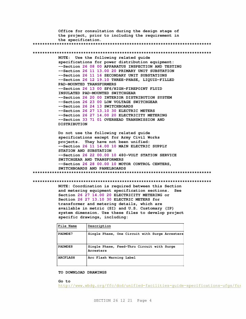
**************************************************************************NOTE: Coor di nat i on i s r equi r ed bet ween t hi s Sect i on and met er i ng equi pment speci f i cat i on sect i ons. See Section 26 27 14. 00 20 ELECTRI CI TY METERI NG or Section 26 27 13. 10 30 ELECTRI C METERS f or t r ansf or mer and met er i ng det ai l s, whi ch ar e avai l abl e i n met r i c ( SI ) and U. S. Cust omar y ( I P) syst em di mensi on. Use t hese f i l es t o devel op pr oj ect speci f i c dr awi ngs, i ncl udi ng:
Fi l e Name Description
PADMDE7 Si ngl e Phase, One Ci r cui t wi t h Sur ge Ar r est er s
PADMDE8 Si ngl e Phase, Feed- Thr u Ci r cui t wi t h Sur ge Arresters
ARCFLASH Ar c Fl ash War ni ng Label
TO DOWNLOAD DRAWI NGS
Go t o http://www.wbdg.org/ffc/dod/unified-facilities-guide-specifications-ufgs/forms-graphics-tables
SECTION 26 12 21 Page 4
Sel ect t he appr opr i at e El ect r i cal . ZI P f i l e( s) and ext r act t he desi r ed det ai l s.
Do not i ncl ude l i s t of det ai l s, or det ai l s t hemsel ves, i n pr oj ect speci f i cat i ons. I nser t t he appr opr i at e det ai l s on dr awi ngs and modi f y opt i onal and bl ank i t ems. I f speci al f eat ur es ar e r equi r ed, do not modi f y det ai l s, but i ndi cat e t hese changes as not es bel ow t he det ai l .
**************************************************************************
**************************************************************************NOTE: Show t he f ol l owi ng i nf or mat i on on t he pr oj ect drawings:
1. Si ngl e- l i ne di agr am showi ng pad- mount ed t r ansf or mer connect or s, i nser t s, sur ge ar r est er s, swi t ches, f uses, cur r ent t r ansf or mer s wi t h r at i ngs, and met er s as appl i cabl e.
2. Gr oundi ng pl an.
3. Type and number of cabl es, and si ze of conduct or s f or each power c i r cui t .
4. Tr ansf or mer pr i mar y and secondar y vol t ages. ( Use I EEE C57. 12. 00, Tabl e 7, " Desi gnat i on of vol t age r at i ngs of s i ngl e- phase wi ndi ngs" ) . St at e t he pr i mar y vol t age ( nomi nal ) act ual l y i n ser vi ce and not t he vol t age cl ass.
5. Speci al condi t i ons, such as al t i t ude, t emper at ur e, and humi di t y; exposur e t o f umes, vapor s, dust , and gases; and sei smi c r equi r ement s.
**************************************************************************
PART 1 GENERAL
1.1 REFERENCES
**************************************************************************NOTE: Thi s par agr aph i s used t o l i s t t he publ i cat i ons c i t ed i n t he t ext of t he gui de speci f i cat i on. The publ i cat i ons ar e r ef er r ed t o i n t he t ext by basi c desi gnat i on onl y and l i s t ed i n t hi s par agr aph by or gani zat i on, desi gnat i on, dat e, and t i t l e.
Use t he Ref er ence Wi zar d' s Check Ref er ence f eat ur e when you add a Ref er ence I dent i f i er ( RI D) out si de of t he Sect i on' s Ref er ence Ar t i c l e t o aut omat i cal l y pl ace t he r ef er ence i n t he Ref er ence Ar t i c l e. Al so use t he Ref er ence Wi zar d' s Check Ref er ence f eat ur e t o updat e t he i ssue dat es.
Ref er ences not used i n t he t ext wi l l aut omat i cal l y be del et ed f r om t hi s sect i on of t he pr oj ect speci f i cat i on when you choose t o r econci l e r ef er ences i n t he publ i sh pr i nt pr ocess.
SECTION 26 12 21 Page 5
**************************************************************************
The publications listed below form a part of this specification to the extent referenced. The publications are referred to within the text by the basic designation only.
AMERICAN CONCRETE INSTITUTE (ACI)
ACI 318 (2014; Errata 1-2 2014; Errata 3-5 2015; Errata 6 2016; Errata 7-9 2017) Building Code Requirements for Structural Concrete (ACI 318-14) and Commentary (ACI 318R-14)
ACI 318M (2014; ERTA 2015) Building Code Requirements for Structural Concrete & Commentary
AMERICAN NATIONAL STANDARDS INSTITUTE (ANSI)
ANSI C12.1 ((2014; Errata 2016) Electric Meters - Code for Electricity Metering
ASTM INTERNATIONAL (ASTM)
ASTM A240/A240M (2018) Standard Specification for Chromium and Chromium-Nickel Stainless Steel Plate, Sheet, and Strip for Pressure Vessels and for General Applications
ASTM C260/C260M (2010a; R 2016) Standard Specification for Air-Entraining Admixtures for Concrete
ASTM D92 (2012a) Standard Test Method for Flash and Fire Points by Cleveland Open Cup Tester
ASTM D97 (2017b) Standard Test Method for Pour Point of Petroleum Products
ASTM D117 (2018) Standard Guide for Sampling, Test Methods, and Specifications for Electrical Insulating Liquids
ASTM D877/D877M (2013) Standard Test Method for Dielectric Breakdown Voltage of Insulating Liquids Using Disk Electrodes
ASTM D1535 (2014; R 2018) Standard Practice for Specifying Color by the Munsell System
ASTM D3487 (2016; E2017) Standard Specification for Mineral Insulating Oil Used in Electrical Apparatus
FM GLOBAL (FM)
FM APP GUIDE (updated on-line) Approval Guide http://www.approvalguide.com/
SECTION 26 12 21 Page 6
INSTITUTE OF ELECTRICAL AND ELECTRONICS ENGINEERS (IEEE)
IEEE 386 (2016) Separable Insulated Connector Systems for Power Distribution Systems Rated 2.5 kV through 35 kV
IEEE C2 (2017; Errata 1-2 2017; INT 1 2017) National Electrical Safety Code
IEEE C37.47 (2011) Standard for High Voltage Distribution Class Current-Limiting Type Fuses and Fuse Disconnecting Switches
IEEE C57.12.00 (2015) General Requirements for Liquid-Immersed Distribution, Power, and Regulating Transformers
IEEE C57.12.25 (1990) Standard for Transformers - Pad-Mounted, Compartmental-Type, Self-Cooled, Single-Phase Distribution Transformers With Separable Insulated High-Voltage Connectors; High Voltage, 34,500 Grdy/ 19,920 Volts and Below; Low Voltage, 240/120 Volts; 167 kVa and Smaller Requirements
IEEE C57.12.28 (2014) Standard for Pad-Mounted Equipment - Enclosure Integrity
IEEE C57.12.29 (2014) Standard for Pad-Mounted Equipment - Enclosure Integrity for Coastal Environments
IEEE C57.12.80 (2010) Standard Terminology for Power and Distribution Transformers
IEEE C57.12.90 (2015; Corr 2017) Test Code for Liquid-Immersed Distribution, Power, and Regulating Transformers
IEEE C57.13 (2016) Requirements for Instrument Transformers
IEEE C57.98 (2011) Guide for Transformer Impulse Tests
IEEE C62.11 (2012) Standard for Metal-Oxide Surge Arresters for Alternating Current Power Circuits (>1kV)
IEEE Stds Dictionary (2009) IEEE Standards Dictionary: Glossary of Terms & Definitions
INTERNATIONAL ELECTRICAL TESTING ASSOCIATION (NETA)
NETA ATS (2017; Errata 2017) Standard for Acceptance Testing Specifications for Electrical Power Equipment and Systems
SECTION 26 12 21 Page 7
NATIONAL ELECTRICAL MANUFACTURERS ASSOCIATION (NEMA)
ANSI C12.7 (2014) Requirements for Watthour Meter Sockets
NEMA 260 (1996; R 2004) Safety Labels for Pad-Mounted Switchgear and Transformers Sited in Public Areas
NEMA Z535.4 (2011; R 2017) Product Safety Signs and Labels
NEMA/ANSI C12.10 (2011) Physical Aspects of Watthour Meters - Safety Standards
NATIONAL FIRE PROTECTION ASSOCIATION (NFPA)
NFPA 70 (2017; ERTA 1-2 2017; TIA 17-1; TIA 17-2; TIA 17-3; TIA 17-4; TIA 17-5; TIA 17-6; TIA 17-7; TIA 17-8; TIA 17-9; TIA 17-10; TIA 17-11; TIA 17-12; TIA 17-13; TIA 17-14; TIA 17-15; TIA 17-16; TIA 17-17 ) National Electrical Code
ORGANISATION FOR ECONOMIC CO-OPERATION AND DEVELOPMENT (OECD)
OECD Test 203 (1992) Fish Acute Toxicity Test
U.S. ENVIRONMENTAL PROTECTION AGENCY (EPA)
EPA 712-C-98-075 (1998) Fate, Transport and Transformation Test Guidelines - OPPTS 835.3100- "Aerobic Aquatic Biodegradation"
EPA 821-R-02-012 (2002) Methods for Measuring the Acute Toxicity of Effluents and Receiving Waters to Freshwater and Marine Organisms
U.S. NATIONAL ARCHIVES AND RECORDS ADMINISTRATION (NARA)
10 CFR 431 Energy Efficiency Program for Certain Commercial and Industrial Equipment
UNDERWRITERS LABORATORIES (UL)
UL 467 (2013; Reprint Jun 2017) UL Standard for Safety Grounding and Bonding Equipment
1.2 RELATED REQUIREMENTS
**************************************************************************NOTE: I ncl ude Sect i on 26 08 00 APPARATUS I NSPECTI ON AND TESTI NG on al l pr oj ect s i nvol v i ng medi um vol t age and speci al i zed power di st r i but i on equi pment .
**************************************************************************
Section 26 08 00 APPARATUS INSPECTION AND TESTING applies to this Section, with the additions and modifications specified herein.
SECTION 26 12 21 Page 8
1.3 DEFINITIONS
Unless otherwise specified or indicated, electrical and electronics terms used in these specifications, and on the drawings, are as defined in IEEE Stds Dictionary .
1.4 SUBMITTALS
**************************************************************************NOTE: Revi ew Submi t t al Descr i pt i on ( SD) def i ni t i ons i n Sect i on 01 33 00 SUBMI TTAL PROCEDURES and edi t t he f ol l owi ng l i s t t o r ef l ect onl y t he submi t t al s r equi r ed f or t he pr oj ect .
The Gui de Speci f i cat i on t echni cal edi t or s have desi gnat ed t hose i t ems t hat r equi r e Gover nment appr oval , due t o t hei r compl exi t y or cr i t i cal i t y, wi t h a " G. " Gener al l y, ot her submi t t al i t ems can be r evi ewed by t he Cont r act or ' s Qual i t y Cont r ol Syst em. Onl y add a " G" t o an i t em, i f t he submi t t al i s suf f i c i ent l y i mpor t ant or compl ex i n cont ext of t he pr oj ect .
For submi t t al s r equi r i ng Gover nment appr oval on Ar my pr oj ect s, a code of up t o t hr ee char act er s wi t hi n t he submi t t al t ags may be used f ol l owi ng t he " G" desi gnat i on t o i ndi cat e t he appr ovi ng aut hor i t y. Codes f or Ar my pr oj ect s usi ng t he Resi dent Management Syst em ( RMS) ar e: " AE" f or Ar chi t ect - Engi neer ; " DO" f or Di st r i ct Of f i ce ( Engi neer i ng Di v i s i on or ot her or gani zat i on i n t he Di st r i ct Of f i ce) ; " AO" f or Ar ea Of f i ce; " RO" f or Resi dent Of f i ce; and " PO" f or Pr oj ect Of f i ce. Codes f ol l owi ng t he " G" t ypi cal l y ar e not used f or Navy, Ai r For ce, and NASA pr oj ect s.
The " S" f ol l owi ng a submi t t al i t em i ndi cat es t hat t he submi t t al i s r equi r ed f or t he Sust ai nabi l i t y eNot ebook t o f ul f i l l f eder al l y mandat ed sust ai nabl e r equi r ement s i n accor dance wi t h Sect i on 01 33 29 SUSTAI NABI LI TY REPORTI NG. Locat e t he " S" submi t t al under t he SD number t hat best descr i bes t he submi t t al i t em.
Choose t he f i r st br acket ed i t em f or Navy, Ai r For ce and NASA pr oj ect s, or choose t he second br acket ed i t em f or Ar my pr oj ect s.
**************************************************************************
Government approval is required for submittals with a "G" designation; submittals not having a "G" designation are [for Contractor Quality Control approval.][for information only. When used, a designation following the "G" designation identifies the office that will review the submittal for the Government.] Submittals with an "S" are for inclusion in the Sustainability eNotebook, in conformance with Section 01 33 29 SUSTAINABILITY REPORTING. Submit the following in accordance with Section 01 33 00 SUBMITTAL PROCEDURES:
SD-02 Shop Drawings
SECTION 26 12 21 Page 9
Pad-Mounted Transformer Drawings ; G[, [_____]]
SD-03 Product Data
Single-Phase Pad-Mounted Transformers (Dead-Front) ; G[, [_____]]
SD-06 Test Reports
Acceptance Checks and Tests ; G[, [_____]]
SD-07 Certificates
Transformer Efficiencies ; G[, [_____]]
SD-09 Manufacturer's Field Reports
Transformer Test Schedule ; G[, [_____]]
Pad-Mounted Transformer Design Tests ; G[, [_____]]
Pad-Mounted Transformer Routine and Other Tests ; G[, [_____]]
SD-10 Operation and Maintenance Data
Transformer(s) , Data Package 5; G[, [_____]]
[ 1.4.1 Government Submittal Review
**************************************************************************NOTE: I ncl ude t hi s br acket ed opt i on on Navy and Ai r For ce pr oj ect s wher e " r each- back suppor t " has al r eady been coor di nat ed wi t h NAVFAC LANT per t he 2nd i nt r oduct or y Techni cal Not e. Add appr opr i at e i nf or mat i on i n Sect i on 01 33 00 SUBMI TTAL PROCEDURES t o coor di nat e wi t h t he speci al r equi r ement s.
**************************************************************************
[Code CI44, NAVFAC LANT, Naval Facilities Engineering Command][_____] will review and approve all submittals in this section requiring Government approval.
][ 1.4.2 Reduced Submittal Requirements
**************************************************************************NOTE: I ncl ude t hi s br acket ed r educed submi t t al r equi r ement s par agr aph on Navy and Ai r For ce Projects.
**************************************************************************
Transformers designed and manufactured by ABB in Jefferson City, MO; by Eaton's Cooper Power Series Transformers in Waukesha, WI; by ERMCO in Dyersburg, TN; or by Howard Industries in Laurel, MS need not submit the entire submittal package requirements of this contract. Instead, submit the following items:
a. A certification, signed by the manufacturer, stating that the manufacturer will meet the technical requirements of this specification.
SECTION 26 12 21 Page 10
b. An outline drawing of the transformer with devices identified (paragraph PAD-MOUNTED TRANSFORMER DRAWINGS, item a).
c. ANSI nameplate data of the transformer (paragraph PAD-MOUNTED TRANSFORMER DRAWINGS, item b).
**************************************************************************NOTE: The desi gner i s r esponsi bl e f or pr ovi di ng pr oper set t i ngs f or secondar y over - cur r ent devi ce( s) t o ensur e pr oper pr ot ect i on of equi pment and coor di nat i on wi t h t r ansf or mer hi gh si de f uses. I ncl ude t he f ol l owi ng opt i on f or t r ansf or mer s ser vi ng secondar y over - cur r ent devi ces cont ai ni ng adj ust abl e t r i ps.
**************************************************************************
[ d. Manufacturer's published time-current curves in PDF format and in electronic format suitable for import or updating into the [EasyPower] [SKM PowerTools for Windows] [_____] computer program of the transformer high side fuses (paragraph PAD-MOUNTED TRANSFORMER DRAWINGS, item e).
] e. Routine and other tests (in PART 2, see paragraph SOURCE QUALITY CONTROL, subparagraph ROUTINE AND OTHER TESTS), conducted by the manufacturer. These tests may be witnessed by the government. Provide transformer test schedule required by submittal item "SD-11 Closeout Submittals". Provide certified copies of the tests.
f. Provide acceptance test reports required by submittal item "SD-06 Test Reports".
g. Provide operation and maintenance manuals required by submittal item "SD-10 Operation and Maintenance Data".
] 1.5 QUALITY ASSURANCE
1.5.1 Pad-Mounted Transformer Drawings
**************************************************************************NOTE: Del et e br acket ed i nf or mat i on f or Navy and Ai r For ce pr oj ect s when separ at e met er i ng speci f i cat i on i s used. May st i l l need f or Ar my and NASA pr oj ect s unt i l met er i ng speci f i cat i on i s uni f i ed.
**************************************************************************
Include the following as a minimum:
a. An outline drawing, including front, top, and side views.
b. IEEE nameplate data.
[ c. Elementary diagrams and wiring diagrams with terminals identified of meter and current transformers.
] d. One-line diagram, including switch(es)[, current transformers, meters,] and fuses.
e. Manufacturer's published time-current curves in PDF format and in
SECTION 26 12 21 Page 11
electronic format suitable for import or updating into the [EasyPower] [SKM PowerTools for Windows] [_____] computer program of the transformer high side fuses.
1.5.2 Regulatory Requirements
In each of the publications referred to herein, consider the advisory provisions to be mandatory, as though the word "shall" or "must" had been substituted for "should" wherever it appears. Interpret references in these publications to the "authority having jurisdiction," or words of similar meaning, to mean the Contracting Officer. Provide equipment, materials, installation, and workmanship in accordance with NFPA 70 unless more stringent requirements are specified or indicated.
1.5.3 Standard Products
Provide materials and equipment that are products of manufacturers regularly engaged in the production of such products which are of equal material, design and workmanship, and:
a. Have been in satisfactory commercial or industrial use for 2 years prior to bid opening including applications of equipment and materials under similar circumstances and of similar size.
b. Have been on sale on the commercial market through advertisements, manufacturers' catalogs, or brochures during the 2-year period.
c. Where two or more items of the same class of equipment are required, provide products of a single manufacturer; however, the component parts of the item need not be the products of the same manufacturer unless stated in this section.
1.5.3.1 Alternative Qualifications
Products having less than a 2-year field service record will be acceptable if a certified record of satisfactory field operation for not less than 6000 hours, exclusive of the manufacturers' factory or laboratory tests, is furnished.
1.5.3.2 Material and Equipment Manufacturing Date
Products manufactured more than 3 years prior to date of delivery to site are not acceptable.
1.6 MAINTENANCE
1.6.1 Additions to Operation and Maintenance Data
**************************************************************************Not e: Del et e br acket ed i nf or mat i on f or Navy and Ai r For ce pr oj ect s when separ at e met er i ng speci f i cat i on i s used. May st i l l need f or Ar my and NASA pr oj ect s unt i l met er i ng speci f i cat i on i s uni f i ed.
**************************************************************************
Submit operation and maintenance data in accordance with Section 01 78 23 OPERATION AND MAINTENANCE DATA and as specified herein. In addition to requirements of Data Package 5, include the following on the actual transformer(s) provided:
SECTION 26 12 21 Page 12
a. An instruction manual with pertinent items and information highlighted.
b. An outline drawing, front, top, and side views.
c. Prices for spare parts and supply list.
d. Routine and field acceptance test reports.
e. Fuse curves for primary fuses.
[ f. Information on watthour demand meter, CT's, and fuse block.
] g. Actual nameplate diagram.
h. Date of purchase.
PART 2 PRODUCTS
2.1 PRODUCT COORDINATION
Products and materials not considered to be pad-mounted transformers and related accessories are specified in[ Section 33 71 01 OVERHEAD TRANSMISSION AND DISTRIBUTION,][ Section 26 20 00 INTERIOR DISTRIBUTION SYSTEM,][ and][ Section 33 71 02 UNDERGROUND ELECTRICAL DISTRIBUTION].
2.2 SINGLE-PHASE PAD-MOUNTED TRANSFORMERS (DEAD-FRONT)
**************************************************************************NOTE: Accor di ng t o I EEE 386, 200 amper e separ abl e i nsul at ed connect or s nor mal l y used on dead- f r ont pad- mount ed t r ansf or mer s have bot h a f aul t c l osur e and a shor t - t i me cur r ent r at i ng of 10, 000 amper es. Ther ef or e, f r om a saf et y st andpoi nt , dead- f r ont conf i gur at i ons whi ch ut i l i ze t hese connect or s shoul d onl y be used at syst em l ocat i ons whi ch have avai l abl e f aul t cur r ent s of l ess t han 10, 000 r ms symmet r i cal amper es.
Nor mal l y use si ngl e compar t ment ( c l am shel l ) t r ansf or mer s. I f t wo- compar t ment t r ansf or mer s ar e r equi r ed, t hei r use must be appr oved by t he t he t echni cal r evi ew aut hor i t y.
Ut i l i zat i on of 35 kV si ngl e- phase t r ansf or mer s i s not a r ecommended desi gn pr act i ce. Ther ef or e, appr oval f or use i s r equi r ed by t he t echni cal r evi ew aut hor i t y and si gni f i cant changes t o t hi s speci f i cat i on woul d be r equi r ed.
Thi s speci f i cat i on does not addr ess t he mat er i al s used f or t he wi ndi ng ( copper ver sus al umi num) and i t i s assumed t hat t he manuf act ur er wi l l pr ovi de t hei r st andar d pr oduct wi t h r espect t o t he wi ndi ng const r uct i on, based on t he cost of mat er i al s at t he t i me of or der accept ance. No f ai l ur e dat a has been obt ai ned i ndi cat i ng t hat copper wi ndi ngs have a l onger l i f e t han al umi num wi ndi ngs. I f copper wi ndi ngs ar e speci f i ed, t he cost i ncr ease f or
SECTION 26 12 21 Page 13
si ngl e- phase di st r i but i on t r ansf or mer s has r ecent l y been about 15 per cent . Do NOT speci f y wi ndi ng materials.
**************************************************************************
IEEE C57.12.25 , IEEE C57.12.28 and as specified herein. Submit manufacturer's information for each component, device, insulating fluid, and accessory provided with the transformer.
2.2.1 Compartment Construction
[ a. Single compartment: Provide Type 1 combination high- and low-voltage compartment, clam shell style, with lockable (having pad-locking provisions) hinged cover and single-point latching. Type 1 is defined by IEEE C57.12.25 .
][ b. Two compartment: Provide high- and low-voltage compartments separated by steel isolating barriers extending the full height and depth of the compartments. Compartment doors:
(1) Hinged lift-off type with stop in open position and three-point latching.
(2) High voltage door fastening accessible only after the low voltage door has been opened.
] 2.2.1.1 High Voltage
**************************************************************************NOTE: Cur r ent pol i cy i s t o use oi l - i mmer sed f uses i n ser i es wi t h cur r ent l i mi t i ng f uses t o achi eve bet t er pr ot ect i on and obt ai n l i f e cycl e cost benefits.
For 15 kV and 25 kV, 200 A bushi ngs, sel ect bushi ng wel l s and bushi ng wel l i nser t s.
Use t wo bushi ng wel l s f or phase- t o- neut r al syst ems and f our bushi ng wel l s f or phase- t o- phase syst ems. Coor di nat e wi t h t r ansf or mer vol t age desi gnat i ons i n par agr aph TRANSFORMER. I f f eed t hr ough appl i cat i ons ar e r equi r ed, speci al t r ansf or mer compar t ment s i z i ng may be necessar y.
I f f eed t hr ough i nser t s ar e used, t hen ensur e t he encl osur e i s speci f i ed t o be wi de enough and deep enough t o cont ai n t he i nser t s wi t h conduct or s terminated.
Del et e dead- br eak connect or s and l oad- br eak swi t ch handl e opt i ons except f or syst ems wi t h a f aul t capabi l i t y gr eat er t han 10, 000 amps or when t he pr i mar y cabl e s i ze i s gr eat er t han No. 4/ 0 AWG. Thi s desi gn r equi r es appr oval of t he t echni cal r evi ew aut hor i t y.
Do not pr ovi de st andof f bushi ngs unl ess t hi s t r ansf or mer i s t he onl y dead- f r ont t r ansf or mer on t he base. Publ i c wor ks nor mal l y car r i es st andof f
SECTION 26 12 21 Page 14
bushi ngs i n t hei r vehi c l es. Pr ovi de pr ot ect i ve caps when pr ovi di ng st andof f bushi ngs and t o cover unused bushi ng wel l i nser t s when not pr ovi di ng sur ge arresters.
Coor di nat e l ead- i n par agr aph wi t h br acket ed opt i ons below.
**************************************************************************
High-voltage portion contains: the incoming line, insulated high-voltage [load-break ][dead-break ]connectors, bushing well inserts,[ feed-through inserts,] [two][four] high-voltage bushing wells configured for loop feed application,[ load-break switch handle(s),] access to oil-immersed fuses,[ dead-front surge arresters,] tap changer handle, connector parking stands[ with insulated standoff bushings],[ protective caps,] and ground pad.
[ a. Insulated high-voltage load-break connectors: IEEE 386 , rated [15][_____] kV, [95][_____] kV BIL. Current rating: 200 amperes rms continuous. Short time rating: 10,000 amperes rms symmetrical for a time duration of 0.17 seconds. Provide connectors and inserts from the same manufacturer. Provide connectors with a steel reinforced hook-stick eye, grounding eye, test point, and arc-quenching contact material.
][ b. Insulated high-voltage dead-break connectors: IEEE 386 , rated [15 kV, 95 kV BIL][25 kV, 125 kV BIL]. Current rating: 600 amperes rms continuous. Short time rating: 25,000 amperes rms symmetrical for a time duration of 0.17 seconds. Provide connectors with a [200 ampere bushing interface for surge arresters,] steel reinforced hook-stick eye, grounding eye, test point, and arc-quenching contact material.
] c. Bushing well inserts[ and feed-through inserts]: IEEE 386 , 200 amperes, [15][_____] kV class. Provide a bushing well insert for each bushing well unless indicated otherwise.[ Provide feed-through inserts as indicated.]
[ d. One-piece bushings: IEEE 386 , 600 amperes, [15][25] kV Class.
][ e. Load-break switch: Radial-feed oil-immersed type rated at [15 kV, 95 kV BIL][25 kV, 125 kV BIL], with a continuous current rating and load-break rating of [200][300][_____] amperes, and a make-and-latch rating of 12,000 rms amperes symmetrical. Locate the switch handle in the high-voltage compartment.
] f. Provide bayonet oil-immersed, expulsion fuses in series with oil-immersed, partial-range, current-limiting fuses. The bayonet fuse links sense both high currents and high oil temperature in order to provide thermal protection to the transformer. Coordinate transformer protection with expulsion fuse clearing low-current faults and current-limiting fuse clearing high-current faults beyond the interrupting rating of the expulsion fuse. Include an oil retention valve inside the bayonet assembly housing, which closes when the fuse holder is removed, and an external drip shield to minimize oil spills. Display a warning label adjacent to the bayonet fuse(s) cautioning against removing or inserting fuses unless the transformer has been de-energized and the tank pressure has been released.
Bayonet fuse assembly: 150 kV BIL.
SECTION 26 12 21 Page 15
**************************************************************************NOTE: Del et e t he br acket ed opt i on r egar di ng pl acement of cur r ent - l i mi t i ng f uses except when l oad- br eak swi t ch i s speci f i ed.
**************************************************************************
Oil-immersed current-limiting fuses: IEEE C37.47 ; 50,000 rms amperes symmetrical interrupting rating at the system voltage specified.[ Connect current-limiting fuses ahead of the radial-feed load-break switch.]
**************************************************************************NOTE: Pr ovi de bushi ng- mount ed el bow t ype ar r est er s at t he ends of al l r adi al s. Pr ovi de ar r est er s f or al l vol t age l evel s above 5 kV.
**************************************************************************
[ g. Surge arresters: IEEE C62.11 , rated [3][6][9][10][12][15][_____] kV, fully shielded, dead-front metal-oxide-varistor, elbow type with resistance-graded gap suitable for plugging into inserts as indicated.
] h. Parking stands: Provide a parking stand near each bushing well.[ Provide insulated standoff bushings for parking of energized load-break connectors on parking stands.]
[ i. Protective caps: IEEE 386 , 200 amperes, [15][25][_____] kV class. Provide insulated protective caps (not shipping caps) for insulating and sealing out moisture from unused bushing well inserts[ and insulated standoff bushings].
] 2.2.1.2 Low Voltage
**************************************************************************NOTE: I nst al l at i on of c i r cui t br eaker s i n t he t r ansf or mer i s not r ecogni zed by I EEE st andar ds, and l i mi t s accessi bi l i t y by cover i ng l ugs, gauges, and accessor i es. Do not use.
Coor di nat e l ead- i n par agr aph wi t h br acket ed opt i ons below.
**************************************************************************
Low-voltage portion contains: low-voltage bushings with NEMA spade terminals, accessories,[ metering,] stainless steel or laser-etched anodized aluminum diagrammatic transformer nameplate, and ground pad.
a. Include the following accessories: drain plug, fill plug, pressure relief device and a liquid level sight gage.
**************************************************************************NOTE: Many Act i v i t i es have, or ar e i n t he pr ocess of , conver t i ng t o basewi de met er i ng syst ems. A uni f i ed met er i ng speci f i cat i on i s under devel opment t o r epl ace t he met er i ng r equi r ement s i n t hi s sect i on.
For s i ngl e- compar t ment ( c l am shel l t ype) t r ansf or mer s, use t he f i r st br acket ed par agr aph t o pr ovi de a sel f - cont ai ned met er base at t he f aci l i t y ser ved by t he t r ansf or mer , such as i ndi v i dual
SECTION 26 12 21 Page 16
housi ng uni t s or l i f t s t at i ons. For t wo- compar t ment t r ansf or mer s, use t he second br acket ed par agr aph bel ow f or Navy pr oj ect s and possi bl y f or Ai r For ce pr oj ect s. Navy pr oj ect s r equi r e use of Sect i on 26 27 14. 00 20 ELECTRI CI TY METERI NG. Ai r For ce pr oj ect s may r equi r e use of Sect i on 26 27 13. 10 30 ELECTRI C METERS. Del et e t he t hi r d br acket ed par agr aphs bel ow f or Ai r For ce and Navy pr oj ect s.
Coor di nat e wi t h t he Act i v i t y and pr ovi de speci f i c r equi r ement s " t o mat ch exi st i ng syst ems" when necessar y. I f speci f y i ng pr opr i et ar y pr oduct s, i nsur e t hat appr opr i at e " Just i f i cat i on and Aut hor i zat i on ( J & A) " document at i on has been obt ai ned by pr oj ect manager and " pr opr i et ar y l anguage r equi r ement s" have been added t o Di v i s i on 1 as wel l as t o t hi s sect i on of t he speci f i cat i ons.
I f t her e ar e any component s ( such as met er s, housi ng, or cur r ent t r ansf or mer s) t hat wi l l be Gover nment Fur ni shed Cont r act or I nst al l ed ( GFCI ) , or Gover nment Fur ni shed Gover nment I nst al l ed ( GFGI ) , edi t Di v i s i on 1 and t hi s speci f i cat i on sect i on.
**************************************************************************
b. Metering
[ For single-compartment (clam shell type) transformers, provide a self-contained meter base at the facility to be served by the transformer, as specified in Section 26 20 00 INTERIOR DISTRIBUTION SYSTEM.
][ For two-compartment transformers, provide as specified in Section [26 27 13.10 30 ELECTRIC METERS][ 26 27 14.00 20 ELECTRICITY METERING].
][ For two-compartment transformers, provide a transformer-rated meter at the secondary portion of the transformer.
[ (1) NEMA/ANSI C12.10 . Provide a socket-mounted electronic programmable outdoor watthour meter, surface mounted flush against the side of the low-voltage compartment as indicated. Program the meter at the factory or in the field. When field programming is performed, turn field programming device over to the Contracting Officer at completion of project. Coordinate the meter to system requirements.
**************************************************************************NOTE: When Sect i on 23 09 00 I NSTRUMENTATI ON AND CONTROL FOR HVAC i s used, coor di nat e met er r equi r ement s. For m 4S, i n t ext bel ow, i s f or s i ngl e- phase, t hr ee- wi r e syst ems, f or ot her syst em conf i gur at i ons, desi gner must det er mi ne t he appr opr i at e f or m desi gnat i on.
**************************************************************************
(a) Design: Provide meter designed for use on a single-phase, three-wire, [240/120][480/240] volt system with two current transformers. Include necessary KYZ pulse initiation hardware for energy monitoring and control system (EMCS)[ as specified in
SECTION 26 12 21 Page 17
Section 23 09 00 INSTRUMENTATION AND CONTROL FOR HVAC].
(b) Coordination: Provide meter coordinated with ratios of current transformers and transformer secondary voltage.
(c) Class: 20; Form: 4S, accuracy: plus or minus 1.0 percentFinish: Class II.
(d) Cover: Polycarbonate and lockable to prevent tampering and unauthorized removal.
(e) Kilowatt-hour register: five digit electronic programmable type.
(f) Demand register:
1. Provide solid state.
2. Meter reading multiplier: Indicate multiplier on the meter face.
3. Demand interval length: programmed for [15][30][60] minutes with rolling demand up to six subintervals per interval.
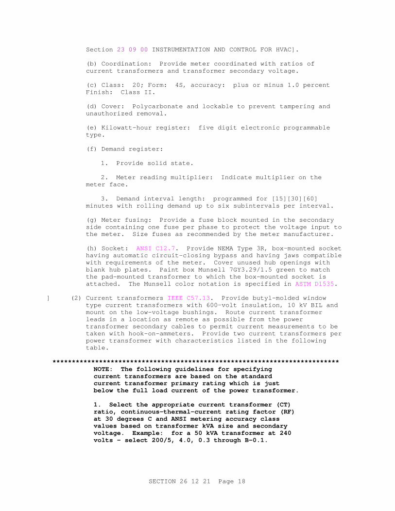
(g) Meter fusing: Provide a fuse block mounted in the secondary side containing one fuse per phase to protect the voltage input to the meter. Size fuses as recommended by the meter manufacturer.
(h) Socket: ANSI C12.7 . Provide NEMA Type 3R, box-mounted socket having automatic circuit-closing bypass and having jaws compatible with requirements of the meter. Cover unused hub openings with blank hub plates. Paint box Munsell 7GY3.29/1.5 green to match the pad-mounted transformer to which the box-mounted socket is attached. The Munsell color notation is specified in ASTM D1535.
] (2) Current transformers IEEE C57.13 . Provide butyl-molded window type current transformers with 600-volt insulation, 10 kV BIL and mount on the low-voltage bushings. Route current transformer leads in a location as remote as possible from the power transformer secondary cables to permit current measurements to be taken with hook-on-ammeters. Provide two current transformers per power transformer with characteristics listed in the following table.
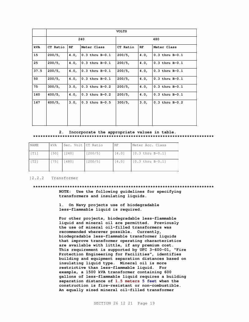
**************************************************************************NOTE: The f ol l owi ng gui del i nes f or speci f y i ng cur r ent t r ansf or mer s ar e based on t he st andar d cur r ent t r ansf or mer pr i mar y r at i ng whi ch i s j ust bel ow t he f ul l l oad cur r ent of t he power t r ansf or mer .
1. Sel ect t he appr opr i at e cur r ent t r ansf or mer ( CT) r at i o, cont i nuous- t her mal - cur r ent r at i ng f act or ( RF) at 30 degr ees C and ANSI met er i ng accur acy c l ass val ues based on t r ansf or mer kVA si ze and secondar y vol t age. Exampl e: f or a 50 kVA t r ansf or mer at 240 vol t s - sel ect 200/ 5, 4. 0, 0. 3 t hr ough B- 0. 1.
SECTION 26 12 21 Page 18
VOLTS
240 480
kVA CT Rat i o RF Met er Cl ass CT Rat i o RF Met er Cl ass
15 200/5, 4.0, 0. 3 t hr u B- 0. 1 200/5, 4.0, 0. 3 t hr u B- 0. 1
25 200/5, 4.0, 0. 3 t hr u B- 0. 1 200/5, 4.0, 0. 3 t hr u B- 0. 1
37.5 200/5, 4.0, 0. 3 t hr u B- 0. 1 200/5, 4.0, 0. 3 t hr u B- 0. 1
50 200/5, 4.0, 0. 3 t hr u B- 0. 1 200/5, 4.0, 0. 3 t hr u B- 0. 1
75 300/5, 3.0, 0. 3 t hr u B- 0. 2 200/5, 4.0, 0. 3 t hr u B- 0. 1
160 400/5, 4.0, 0. 3 t hr u B- 0. 2 200/5, 4.0, 0. 3 t hr u B- 0. 1
167 600/5, 3.0, 0. 3 t hr u B- 0. 5 300/5, 3.0, 0. 3 t hr u B- 0. 2
2. I ncor por at e t he appr opr i at e val ues i n t abl e.**************************************************************************
NAME kVA Sec. Volt CT Ratio RF Meter Acc. Class
[T1] [50] [240] [200/5] [4.0] [0.3 thru B-0.1]
[T2] [75] [480] [200/5] [4.0] [0.3 thru B-0.1]
] 2.2.2 Transformer
**************************************************************************NOTE: Use t he f ol l owi ng gui del i nes f or speci f y i ng t r ansf or mer s and i nsul at i ng l i qui ds.
1. On Navy pr oj ect s use of bi odegr adabl e l ess- f l ammabl e l i qui d i s r equi r ed.
For ot her pr oj ect s, bi odegr adabl e l ess- f l ammabl e l i qui d and mi ner al oi l ar e per mi t t ed. Pr evi ousl y t he use of mi ner al oi l - f i l l ed t r ansf or mer s was r ecommended wher ever possi bl e. Cur r ent l y, bi odegr adabl e l ess- f l ammabl e t r ansf or mer l i qui ds t hat i mpr ove t r ansf or mer oper at i ng char act er i st i cs ar e avai l abl e wi t h l i t t l e, i f any pr emi um cost . Thi s r equi r ement i s suppor t ed by UFC 3- 600- 01, " Fi r e Pr ot ect i on Engi neer i ng f or Faci l i t i es" , i dent i f i es bui l di ng and equi pment separ at i on di st ances based on i nsul at i ng l i qui d t ype. Mi ner al oi l i s mor e r est r i ct i ve t han l ess- f l ammabl e l i qui d. For exampl e, a 1500 kVA t r ansf or mer cont ai ni ng 600 gal l ons of l ess- f l ammabl e l i qui d r equi r es a bui l di ng separ at i on di st ance of 1. 5 met er s 5 f eet when t he const r uct i on i s f i r e- r esi st ant or non- combust i bl e. An equal l y s i zed mi ner al oi l - f i l l ed t r ansf or mer
SECTION 26 12 21 Page 19
requires 4. 6 met er s 15 f eet and 7. 6 met er s 25 f eet of separ at i on f or f i r e- r esi st ant and non- combust i bl e const r uct i on, r espect i vel y. Do not speci f y s i l i cone- f i l l ed t r ansf or mer s.
2. Use I EEE C57. 12. 00, Tabl e 7, vol t age desi gnat i ons, such as " 4160 V - 240/ 120 V" f or t r ansf or mer s connect ed phase- phase on t he pr i mar y s i de, or " 4160Gr dY/ 2400 V - 240/ 120 V" f or t r ansf or mer s connect ed phase- neut r al on t he pr i mar y s i de. Coor di nat e t he number of bushi ng wel l s ( ei t her t wo or f our dependi ng on phase- t o- neut r al , or phase- t o- phase syst ems) wi t h t he pr i mar y vol t age.
3. Tap r at i ngs may var y f r om t hose i ndi cat ed, especi al l y i n l ower kVA r at i ngs.
4. I ncl ude br acket ed opt i on t o di spl ay t r ansf or mer r at i ng on encl osur e when di r ect ed by Act i v i t y. For NASA pr oj ect s onl y, i ncl ude 3 i nch yel l ow l et t er i ng br acket ed opt i ons.
**************************************************************************
a. Less-flammable[ bio-based] liquid-insulated[ or oil-insulated], two winding, 60 hertz, 65 degrees C rise above a 30 degrees C average ambient, self-cooled type.
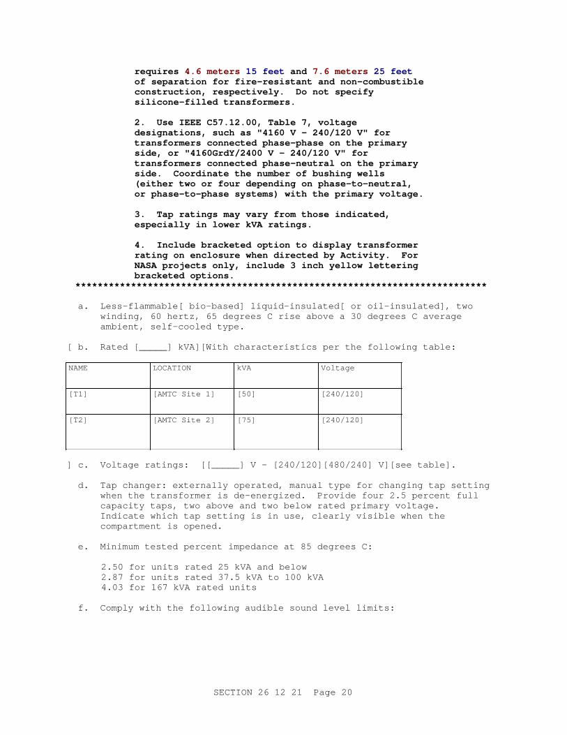
[ b. Rated [_____] kVA][With characteristics per the following table:
NAME LOCATION kVA Voltage
[T1] [AMTC Site 1] [50] [240/120]
[T2] [AMTC Site 2] [75] [240/120]
] c. Voltage ratings: [[_____] V - [240/120][480/240] V][see table].
d. Tap changer: externally operated, manual type for changing tap setting when the transformer is de-energized. Provide four 2.5 percent full capacity taps, two above and two below rated primary voltage. Indicate which tap setting is in use, clearly visible when the compartment is opened.
e. Minimum tested percent impedance at 85 degrees C:
2.50 for units rated 25 kVA and below2.87 for units rated 37.5 kVA to 100 kVA4.03 for 167 kVA rated units
f. Comply with the following audible sound level limits:
SECTION 26 12 21 Page 20
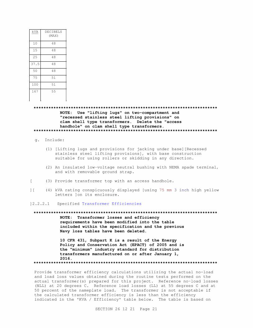
kVA DECIBELS(MAX)
10 48
15 48
25 48
37.5 48
50 48
75 51
100 51
167 55
**************************************************************************NOTE: Use " l i f t i ng l ugs" on t wo- compar t ment and " r ecessed st ai nl ess st eel l i f t i ng pr ovi s i ons" on cl am shel l t ype t r ansf or mer s. Del et e t he " access handhol e" on cl am shel l t ype t r ansf or mer s.
**************************************************************************
g. Include:
(1) [Lifting lugs and provisions for jacking under base][Recessed stainless steel lifting provisions], with base construction suitable for using rollers or skidding in any direction.
(2) An insulated low-voltage neutral bushing with NEMA spade terminal, and with removable ground strap.
[ (3) Provide transformer top with an access handhole.
][ (4) kVA rating conspicuously displayed [using 75 mm 3 inch high yellow letters ]on its enclosure.
] 2.2.2.1 Specified Transformer Efficiencies
**************************************************************************NOTE: Tr ansf or mer l osses and ef f i c i ency r equi r ement s have been modi f i ed i nt o t he t abl e i ncl uded wi t hi n t he speci f i cat i on and t he pr evi ous Navy l oss t abl es have been del et ed.
10 CFR 431, Subpar t K i s a r esul t of t he Ener gy Pol i cy and Conser vat i on Act ( EPACT) of 2005 and i s t he " mi ni mum" i ndust r y st andar d f or di st r i but i on t r ansf or mer s manuf act ur ed on or af t er Januar y 1, 2016.
**************************************************************************
Provide transformer efficiency calculations utilizing the actual no-load and load loss values obtained during the routine tests performed on the actual transformer(s) prepared for this project. Reference no-load losses (NLL) at 20 degrees C. Reference load losses (LL) at 55 degrees C and at 50 percent of the nameplate load. The transformer is not acceptable if the calculated transformer efficiency is less than the efficiency indicated in the "KVA / Efficiency" table below. The table is based on
SECTION 26 12 21 Page 21
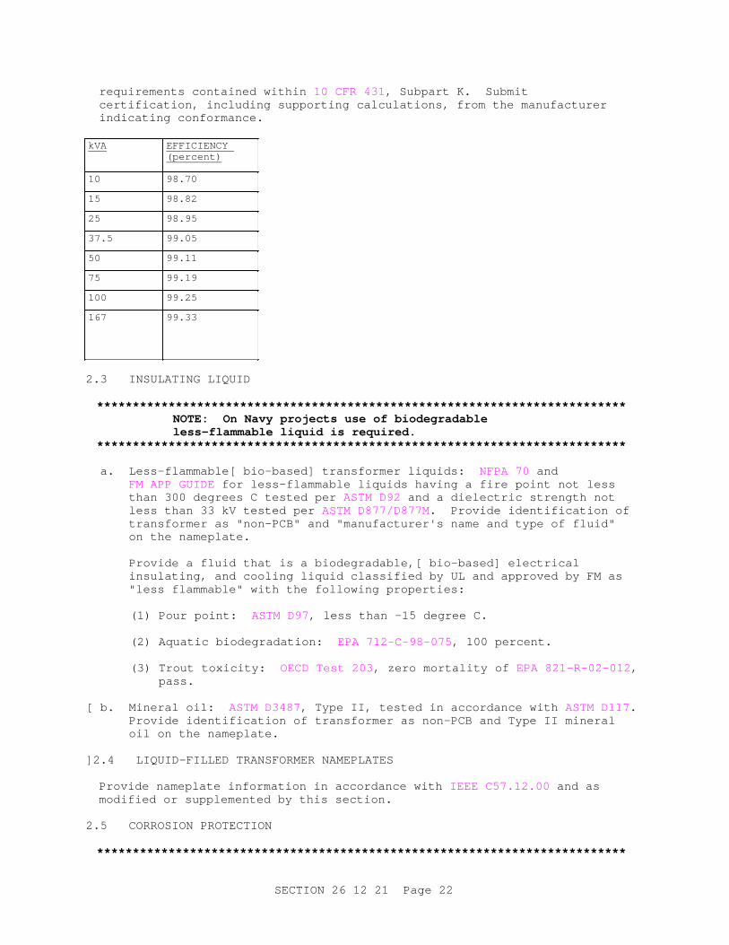
requirements contained within 10 CFR 431 , Subpart K. Submit certification, including supporting calculations, from the manufacturer indicating conformance.
kVA EFFICIENCY (percent)
10 98.70
15 98.82
25 98.95
37.5 99.05
50 99.11
75 99.19
100 99.25
167 99.33
2.3 INSULATING LIQUID
**************************************************************************NOTE: On Navy pr oj ect s use of bi odegr adabl e l ess- f l ammabl e l i qui d i s r equi r ed.
**************************************************************************
a. Less-flammable[ bio-based] transformer liquids: NFPA 70 and FM APP GUIDE for less-flammable liquids having a fire point not less than 300 degrees C tested per ASTM D92 and a dielectric strength not less than 33 kV tested per ASTM D877/D877M. Provide identification of transformer as "non-PCB" and "manufacturer's name and type of fluid" on the nameplate.
Provide a fluid that is a biodegradable,[ bio-based] electrical insulating, and cooling liquid classified by UL and approved by FM as "less flammable" with the following properties:
(1) Pour point: ASTM D97, less than -15 degree C.
(2) Aquatic biodegradation: EPA 712-C-98-075 , 100 percent.
(3) Trout toxicity: OECD Test 203 , zero mortality of EPA 821-R-02-012 , pass.
[ b. Mineral oil: ASTM D3487, Type II, tested in accordance with ASTM D117. Provide identification of transformer as non-PCB and Type II mineral oil on the nameplate.
] 2.4 LIQUID-FILLED TRANSFORMER NAMEPLATES
Provide nameplate information in accordance with IEEE C57.12.00 and as modified or supplemented by this section.
2.5 CORROSION PROTECTION
**************************************************************************
SECTION 26 12 21 Page 22
NOTE: Use st ai nl ess st eel bases and cabi net s f or most appl i cat i ons. I n host i l e envi r onment s, t he addi t i onal cost of t ot al l y st ai nl ess st eel t anks and met er i ng encl osur es may be j ust i f i ed. Manuf act ur er ' s st andar d const r uct i on mat er i al i s accept abl e onl y i n noncoast al and noncor r osi ve envi r onment s. Choose t he second mai n br acket ed opt i on f or host i l e envi r onment s.
**************************************************************************
[ Provide corrosion resistant bases and cabinets of transformers, fabricated of stainless steel conforming to ASTM A240/A240M , Type 304 or 304L. Base includes any part of pad-mounted transformer that is within 75 mm 3 inches of concrete pad.
][ Provide entire transformer assembly, including tank and radiator, base, enclosure, and metering enclosure fabricated of stainless steel conforming to ASTM A240/A240M , Type 304 or 304L. Form enclosure of stainless steel sheets. The optional use of aluminum is permitted for the metering enclosure.
] Paint entire transformer assembly [Munsell 7GY3.29/1.5 green][Munsell 5BG7.0/0.4 sky gray (ANSI 70)][_____], with paint coating system complying with IEEE C57.12.28 [and IEEE C57.12.29 ]regardless of base, cabinet, and tank material. The Munsell color notation is specified in ASTM D1535.
2.6 WARNING SIGNS AND LABELS
Provide warning signs for the enclosures of pad-mounted transformers having a nominal rating exceeding 600 volts in accordance with NEMA Z535.4 and NEMA 260.
a. When the enclosure integrity of such equipment is specified to be in accordance with IEEE C57.12.28 , such as for pad-mounted transformers, provide self-adhesive warning labels on the outside of the high voltage compartment door(s) with nominal dimensions of 178 by 255 mm 7 by 10 inches with the legend "WARNING HIGH VOLTAGE" printed in two lines of nominal 50 mm 2 inch high letters. Include the word "WARNING" in white letters on an orange background and the words "HIGH VOLTAGE" in black letters on a white background.
[ b. When such equipment is guarded by a fence, mount signs on the fence. Provide metal signs having nominal dimensions of 355 by 255 mm 14 by 10 inches with the legend "WARNING HIGH VOLTAGE KEEP OUT" printed in three lines of nominal 75 mm 3 inch high white letters on an orange and black field.
]**************************************************************************
NOTE: I ncl ude t he Ar c Fl ash War ni ng Label det ai l on t he dr awi ngs. See t he t echni cal not es at t he begi nni ng of sect i on t o obt ai n t he Aut oCAD dr awi ng f i l e of t he l abel .
**************************************************************************
Provide arc flash warning label for the enclosure of pad-mounted transformers. Locate this self-adhesive warning label on the outside of the high voltage compartment side warning of potential electrical arc flash hazards and appropriate PPE required. Provide label format as
SECTION 26 12 21 Page 23
indicated.
2.7 GROUNDING AND BONDING
UL 467 . Provide grounding and bonding as specified in Section 33 71 02 UNDERGROUND ELECTRICAL DISTRIBUTION.
[ 2.8 PADLOCKS
**************************************************************************NOTE: Desi gner must assur e t hat Sect i on 08 71 00 DOOR HARDWARE i s i ncl uded and i s edi t ed t o i ncl ude padlocks.
Do not use t hi s par agr aph f or Navy and Ai r For ce projects.
**************************************************************************
Provide padlocks for pad-mounted equipment[ and for each fence gate], keyed [alike][as directed by the Contracting Officer]. Comply with Section 08 71 00 DOOR HARDWARE.
] 2.9 CAST-IN-PLACE CONCRETE
**************************************************************************NOTE: Use t he f i r st br acket ed par agr aph when pr oj ect i ncl udes a concr et e sect i on i n Di v i s i on 03; ot her wi se, t he second br acket ed par agr aph may be used. Coor di nat e r equi r ement s wi t h Sect i on 03 30 00 CAST- I N- PLACE CONCRETE.
**************************************************************************
[ Provide concrete associated with electrical work for other than encasement of underground ducts rated for 30 MPa 4000 psi minimum 28-day compressive strength unless specified otherwise. Conform to the requirements of Section 03 30 00 CAST-IN-PLACE CONCRETE.
]**************************************************************************
NOTE: I f concr et e r equi r ement s ar e det ai l ed and no cast - i n- pl ace sect i on i s t o be i ncl uded i n t he pr oj ect speci f i cat i on, r ef er t o Sect i on 03 30 00 CAST- I N- PLACE CONCRETE and sel ect such por t i ons as needed t o pr ovi de compl et e r equi r ement s i n addi t i on t o t he r equi r ement s bel ow.
**************************************************************************
[ Provide concrete associated with electrical work as follows:
a. Composed of fine aggregate, coarse aggregate, portland cement, and water so proportioned and mixed as to produce a plastic, workable mixture.
b. Fine aggregate: hard, dense, durable, clean, and uncoated sand.
c. Coarse aggregate: reasonably well graded from 4.75 mm to 25 mm 3/16 inch to 1 inch .
d. Fine and coarse aggregates: free from injurious amounts of dirt, vegetable matter, soft fragments or other deleterious substances.
SECTION 26 12 21 Page 24
e. Water: fresh, clean, and free from salts, alkali, organic matter, and other impurities.
f. Concrete associated with electrical work for other than encasement of underground ducts: 30 MPa 4000 psi minimum 28-day compressive strength unless specified otherwise.
g. Slump: Less than 100 mm 4 inches . Retempering of concrete will not be permitted.
h. Exposed, unformed concrete surfaces: smooth, wood float finish.
i. Concrete must be cured for a period of not less than 7 days, and concrete made with high early strength portland cement must be repaired by patching honeycombed or otherwise defective areas with cement mortar as directed by the Contracting Officer.
j. Air entrain concrete exposed to weather using an air-entraining admixture conforming to ASTM C260/C260M.
k. Air content: between 4 and 6 percent.
] 2.10 SOURCE QUALITY CONTROL
2.10.1 Transformer Test Schedule
The Government reserves the right to witness tests. Provide transformer test schedule for tests to be performed at the manufacturer's test facility. Submit required test schedule and location, and notify the Contracting Officer 30 calendar days before scheduled test date. Notify Contracting Officer 15 calendar days in advance of changes to scheduled date.
2.10.2 Test Instrument Calibration
a. Provide a calibration program which assures that all applicable test instruments are maintained within rated accuracy.
b. Accuracy: Traceable to the National Institute of Standards and Technology.
c. Instrument calibration frequency schedule: less than or equal to 12 months for both test floor instruments and leased specialty equipment.
d. Dated calibration labels: visible on all test equipment.
e. Calibrating standard: higher accuracy than that of the instrument tested.
f. Keep up-to-date records that indicate dates and test results of instruments calibrated or tested. For instruments calibrated by the manufacturer on a routine basis, in lieu of third party calibration, include the following:
(1) Maintain up-to-date instrument calibration instructions and procedures for each test instrument.
(2) Identify the third party/laboratory calibrated instrument to
SECTION 26 12 21 Page 25
verify that calibrating standard is met.
2.10.3 Design Tests
IEEE C57.12.00 , and IEEE C57.12.90 . Section 5.1.2 in IEEE C57.12.80 states that "design tests are made only on representative apparatus of basically the same design." Submit design test reports (complete with test data, explanations, formulas, and results), in the same submittal package as the catalog data and drawings for[ each of] the specified transformer(s), with design tests performed prior to the award of this contract.
a. Tests: certified and signed by a registered professional engineer.
b. Temperature rise: "Basically the same design" for the temperature rise test means a pad-mounted transformer with the same coil construction (such as wire wound primary and sheet wound secondary), the same kVA, the same cooling type (ONAN), the same temperature rise rating, and the same insulating liquid as the transformer specified.
c. Lightning impulse: "Basically the same design" for the lightning impulse dielectric test means a pad-mounted transformer with the same BIL, the same coil construction (such as wire wound primary and sheet wound secondary), and a tap changer, if specified. Design lightning impulse tests includes the primary windings only of that transformer.
(1) IEEE C57.12.90 , paragraph 10.3 entitled "Lightning Impulse Test Procedures," and IEEE C57.98 .
(2) State test voltage levels.
(3) Provide photographs of oscilloscope display waveforms or plots of digitized waveforms with test report.
d. Lifting and moving devices: "Basically the same design" requirement for the lifting and moving devices test means a test report confirming that the lifting device being used is capable of handling the weight of the specified transformer in accordance with IEEE C57.12.25 .
e. Pressure: "Basically the same design" for the pressure test means a pad-mounted transformer with a tank volume within 30 percent of the tank volume of the transformer specified.
f. Short circuit: "Basically the same design" for the short circuit test means a pad-mounted transformer with the same kVA as the transformer specified.
2.10.4 Routine and Other Tests
IEEE C57.12.00 . Routine and other tests: performed by the manufacturer on[ each of] the actual transformer(s) prepared for this project to ensure that the design performance is maintained in production. Submit test reports, by serial number and receive approval before delivery of equipment to the project site. Required tests include:
a. Polarity.
b. Ratio.
SECTION 26 12 21 Page 26
c. No-load losses (NLL) and excitation current.
d. Load losses (LL) and impedance voltage.
e. Dielectric.
(1) Impulse.
(2) Applied voltage.
(3) Induced voltage.
f. Leak.
PART 3 EXECUTION
3.1 INSTALLATION
Conform to IEEE C2 , NFPA 70 , and to requirements specified herein. Provide new equipment and materials unless indicated or specified otherwise.
3.2 GROUNDING
NFPA 70 and IEEE C2 , except provide grounding systems with a resistance to solid earth ground not exceeding [25][_____] ohms.
3.2.1 Grounding Electrodes
Provide driven ground rods as specified in Section 33 71 02 UNDERGROUND ELECTRICAL DISTRIBUTION. Connect ground conductors to the upper end of ground rods by exothermic weld or compression connector. Provide compression connectors at equipment end of ground conductors.
3.2.2 Pad-Mounted Transformer Grounding
**************************************************************************NOTE: Ensur e pl ans show t he secondar y neut r al gr oundi ng conduct or s i zed i n accor dance wi t h NFPA 70 and t he pr i mar y neut r al gr oundi ng conduct or when r equi r ed. Ensur e t he CADD det ai l used mat ches how t hi s par agr aph i s edi t ed. Tr ansf or mer i s t o have a gr ound r i ng and t he nor mal number of gr ound r ods i s ei t her f our or t wo. The one gr ound r od opt i on shoul d onl y be chosen i f r equi r ed by l ocal i nst al l at i on r equi r ement s.
**************************************************************************
Provide a ground ring around the transformer with [1/0][4/0] AWG bare copper.[ Provide four ground rods in the ground ring, one per corner.][ Provide two ground rods in the ground ring at opposite corners.][ Provide one ground rod in the ground ring with the ground rod located in the transformer cabinet.] Install the ground rods at least 3000 mm 10 feet apart from each other. Provide separate copper grounding conductors and connect them to the ground loop as indicated. When work in addition to that indicated or specified is required to obtain the specified ground resistance, the provision of the contract covering "Changes" applies.
SECTION 26 12 21 Page 27
3.2.3 Connections
Make joints in grounding conductors and loops by exothermic weld or compression connector. Install exothermic welds and compression connectors as specified in Section 33 71 02 UNDERGROUND ELECTRICAL DISTRIBUTION.
3.2.4 Grounding and Bonding Equipment
UL 467 , except as indicated or specified otherwise.
3.3 INSTALLATION OF EQUIPMENT AND ASSEMBLIES
Install and connect pad-mounted transformers furnished under this section as indicated on project drawings, the approved shop drawings, and as specified herein.
[ 3.3.1 Meters and Current Transformers
**************************************************************************Not e: Del et e br acket ed par agr aph f or Navy and Ai r For ce pr oj ect s, t hi s i nf or mat i on i s cover ed i n t hei r associ at ed met er i ng speci f i cat i ons.
**************************************************************************
ANSI C12.1 .
] 3.4 FIELD APPLIED PAINTING
Where field painting of enclosures is required to correct damage to the manufacturer's factory applied coatings, provide manufacturer's recommended coatings and apply in accordance with manufacturer's instructions.
[ 3.5 WARNING SIGN MOUNTING
**************************************************************************NOTE: I ncl ude t he f ol l owi ng opt i on when pad- mount ed t r ansf or mer i s guar ded by a f ence.
**************************************************************************
Provide the number of signs required to be readable from each accessible side, but space the signs a maximum of 9 meters 30 feet apart.
] 3.6 FOUNDATION FOR EQUIPMENT AND ASSEMBLIES
**************************************************************************NOTE: Mount i ng s l ab connect i ons may have t o be gi ven i n det ai l dependi ng on t he r equi r ement s f or t he sei smi c zone i n whi ch t he r equi r ement i s l ocat ed. I ncl ude const r uct i on r equi r ement s f or concr et e s l ab onl y i f s l ab i s not det ai l ed i n dr awi ngs. Do not pr ovi de cur bs or r ai sed edges ar ound l i qui d f i l l ed t r ansf or mer s unl ess speci f i cal l y appr oved by Techni cal Pr oponent ( l i nk pr ovi ded i n t he t echni cal not e at t he begi nni ng of t hi s sect i on) .
**************************************************************************
SECTION 26 12 21 Page 28
Mount transformer on concrete slab as follows:
a. Unless otherwise indicated, provide the slab with dimensions at least 200 mm 8 inches thick, reinforced with a 152 by 152 mm MW19 by MW19 6 by 6 inches - W2.9 by W2.9 mesh placed uniformly 100 mm 4 inches from the top of the slab.
b. Place slab on a 150 mm 6 inch thick, well-compacted gravel base.
c. Install slab such that top of concrete slab is approximately 100 mm 4 inches above the finished grade with gradual slope for drainage.
d. Provide edges above grade with 15 mm 1/2 inch chamfer.
e. Provide slab of adequate size to project at least 200 mm 8 inches beyond the equipment.
Stub up conduits, with bushings, 50 mm 2 inches into cable wells in the concrete pad. Coordinate dimensions of cable wells with transformer cable training areas.
3.6.1 Cast-In-Place Concrete
**************************************************************************NOTE: Use t he f i r st br acket ed opt i on when pr oj ect i ncl udes a concr et e sect i on i n Di v i s i on 03; ot her wi se, t he second br acket ed opt i on may be used.
**************************************************************************
Provide cast-in-place concrete work in accordance with the requirements of [Section 03 30 00 CAST-IN-PLACE CONCRETE][ ACI 318M ACI 318 ].
[ 3.6.2 Sealing
**************************************************************************NOTE: Requi r e seal i ng of cabl e wel l s ( wi ndows) i n t he concr et e pad i f r odent i nt r usi on i s a pr obl em.
**************************************************************************
When the installation is complete, seal all entries into the equipment enclosure with an approved sealing method. Provide seals of sufficient strength and durability to protect all energized live parts of the equipment from rodents, insects, or other foreign matter.
] 3.7 FIELD QUALITY CONTROL
3.7.1 Performance of Acceptance Checks and Tests
Perform in accordance with the manufacturer's recommendations, and include the following visual and mechanical inspections and electrical tests, performed in accordance with NETA ATS. Submit reports, including acceptance criteria and limits for each test in accordance with NETA ATS "Test Values".
3.7.1.1 Pad-Mounted Transformers
a. Visual and mechanical inspection.
(1) Compare equipment nameplate information with specifications and
SECTION 26 12 21 Page 29
approved shop drawings.
(2) Inspect physical and mechanical condition. Check for damaged or cracked insulators and leaks.
(3) Inspect anchorage, alignment, and grounding.
(4) Verify the presence of PCB content labeling.
(5) Verify the bushings and transformer interiors are clean.
(6) Inspect all bolted electrical connections for high resistance using low-resistance ohmmeter, verifying tightness of accessible bolted electrical connections by calibrated torque-wrench method, or performing thermographic survey.
(7) Verify correct liquid level in tanks.
(8) Verify that positive pressure is maintained on gas-blanketed transformers.
(9) Perform specific inspections and mechanical tests as recommended by manufacturer.
(10) Verify correct equipment grounding.
[ (11) Verify the presence of transformer surge arresters.
] b. Electrical tests.
(1) Perform resistance measurements through all bolted connections with low-resistance ohmmeter.
(2) Verify proper secondary voltage phase-to-phase and phase-to-neutral after energization and prior to loading.
**************************************************************************NOTE: I ncl ude t he br acket ed opt i on f or addi t i onal f i el d el ect r i cal t est s f or NASA pr oj ect s onl y.
**************************************************************************
[ (3) Perform insulation-resistance tests, winding-to-winding and each winding-to-ground. Calculate polarization index.
(4) Perform turns-ratio tests at all tap positions.
(5) Perform insulation power-factor or dissipation-factor tests on all windings in accordance with test equipment manufacturer's published data.
(6) Perform power-factor or dissipation-factor tests on each bushing equipped with a power-factor/capacitance tap. In the absence of a power-factor/capacitance tap, perform hot-collar tests.
(7) Measure the resistance of each high-voltage winding in each de-energized tap-changer position. Measure the resistance of each low-voltage winding in each de-energized tap-changer position, if applicable.
SECTION 26 12 21 Page 30
(8) Remove and test a sample of insulating liquid for the following: Dielectric breakdown voltage, Acid neutralization number, Specific gravity, Interfacial tension, Color, Visual Condition, Water in insulating liquids (Required on 25 kV or higher voltages and on all silicone-filled units.), and Power factor or dissipation factor.
(9) Perform dissolved-gas analysis (DGA) on a sample of insulating liquid.
] [ 3.7.1.2 Current Transformers
**************************************************************************NOTE: Del et e br acket ed opt i onal par agr aphs f or Navy and Ai r For ce pr oj ect s. Thi s i nf or mat i on i s cover ed i n t hei r associ at ed met er i ng speci f i cat i ons.
**************************************************************************
a. Visual and mechanical inspection.
(1) Compare equipment nameplate data with specifications and approved shop drawings.
(2) Inspect physical and mechanical condition.
(3) Verify correct connection.
(4) Verify that adequate clearances exist between primary and secondary circuit wiring.
(5) Verify the unit is clean.
(6) Inspect all bolted electrical connections for high resistance using low-resistance ohmmeter, verifying tightness of accessible bolted electrical connections by calibrated torque-wrench method, or performing thermographic survey.
(7) Verify that all required grounding and shorting connections provide good contact.
(8) Verify correct operation of transformer withdrawal mechanism and grounding operation.
(9) Verify appropriate lubrication on moving current-carrying parts and on moving and sliding surfaces.
b. Electrical tests.
(1) Perform resistance measurements through all bolted connections with low-resistance ohmmeter, if applicable.
(2) Perform insulation-resistance test.
(3) Perform a polarity test.
(4) Perform a ratio-verification test.
SECTION 26 12 21 Page 31
][ 3.7.1.3 Watthour Meter
**************************************************************************NOTE: Del et e br acket ed opt i onal par agr aphs f or Navy and Ai r For ce pr oj ect s. Thi s i nf or mat i on i s cover ed i n t hei r associ at ed met er i ng speci f i cat i ons.
**************************************************************************
a. Visual and mechanical inspection.
(1) Compare equipment nameplate data with specifications and approved shop drawings.
(2) Inspect physical and mechanical condition.
(3) Verify tightness of electrical connections.
b. Electrical tests.
(1) Calibrate watthour meters according to manufacturer's published data.
(2) Verify that correct multiplier has been placed on face of meter, where applicable.
(3) Verify that current transformer secondary circuits are intact.
] 3.7.1.4 Grounding System
a. Visual and mechanical inspection.
(1) Inspect ground system for compliance with contract plans and specifications.
b. Electrical tests.
(1) Perform ground-impedance measurements utilizing the fall-of-potential method. On systems consisting of interconnected ground rods, perform tests after interconnections are complete. On systems consisting of a single ground rod perform tests before any wire is connected. Take measurements in normally dry weather, not less than 48 hours after rainfall. Use a portable ground resistance tester in accordance with manufacturer's instructions to test each ground or group of grounds. Use an instrument equipped with a meter reading directly in ohms or fractions thereof to indicate the ground value of the ground rod or grounding systems under test.
(2) Submit the measured ground resistance of each ground rod and grounding system, indicating the location of the rod and grounding system. Include the test method and test setup (i.e., pin location) used to determine ground resistance and soil conditions at the time the measurements were made.
[ 3.7.1.5 Surge Arresters, Medium- and High-Voltage
a. Visual and mechanical inspection.
(1) Compare equipment nameplate data with specifications and approved
SECTION 26 12 21 Page 32
shop drawings.
(2) Inspect physical and mechanical condition.
(3) Inspect anchorage, alignment, grounding, and clearances.
(4) Verify the arresters are clean.
(5) Inspect all bolted electrical connections for high resistance using low-resistance ohmmeter, verifying tightness of accessible bolted electrical connections by calibrated torque-wrench method, or performing thermographic survey.
(6) Verify that the ground lead on each device is individually attached to a ground bus or ground electrode.
b. Electrical tests.
(1) Perform resistance measurements through all bolted connections with low-resistance ohmmeter, if applicable.
(2) Perform an insulation-resistance test on each arrester, phase terminal-to-ground.
(3) Test grounding connection.
] 3.7.2 Follow-Up Verification
Upon completion of acceptance checks and tests, show by demonstration in service that circuits and devices are in good operating condition and properly performing the intended function. As an exception to requirements stated elsewhere in the contract, notify the Contracting Officer 5 working days in advance of the dates and times of checking and testing.
-- End of Section --
SECTION 26 12 21 Page 33