ufgs 33 61 13 pre-engineered underground heat distribution ... 33 61 13.pdf · 1.5.3 corrosion...
TRANSCRIPT
**************************************************************************USACE / NAVFAC / AFCEC / NASA UFGS- 33 61 13 ( August 2010) Change 1 - 02/ 20 - - - - - - - - - - - - - - - - - - - - - - - - - - -Pr epar i ng Act i v i t y: USACE Super sedi ng UFGS- 33 61 13 ( Apr i l 2008)
UNI FI ED FACI LI TI ES GUI DE SPECI FI CATI ONS
Ref er ences ar e i n agr eement wi t h UMRL dat ed Januar y 2020**************************************************************************
SECTION TABLE OF CONTENTS
DIVISION 33 - UTILITIES
SECTION 33 61 13
PRE-ENGINEERED UNDERGROUND HEAT DISTRIBUTION SYSTEM
08/10
PART 1 GENERAL
1.1 REFERENCES 1.2 DEFINITIONS 1.2.1 Heat Distribution System 1.2.2 Direct-Buried 1.2.3 UHDS Types 1.2.3.1 Drainable-Dryable-Testable (DDT) Direct-Buried 1.2.3.2 Water Spread Limiting (WSL) Direct-Buried 1.2.3.3 Water Spread Limiting Poured-In-Place Insulation (PIPI) 1.3 SYSTEM DESCRIPTION 1.3.1 Scope 1.3.2 UHDS Design 1.3.3 Cathodic Protection 1.3.4 Operating Characteristics 1.3.5 Rated Characteristics 1.4 SUBMITTALS 1.5 QUALITY ASSURANCE 1.5.1 Manufacturer 1.5.2 Manufacturer's Representative 1.5.3 Corrosion Engineer 1.5.4 Testing Firm 1.5.5 Contract drawings 1.6 DELIVERY, STORAGE, AND HANDLING 1.7 SITE CONDITIONS
PART 2 PRODUCTS
2.1 STANDARD PRODUCTS 2.2 FACTORY FABRICATED, DIRECT-BURIED DDT SYSTEMS 2.2.1 DDT Steam and High Temperature Hot Water Carrier Pipes 2.2.2 DDT Condensate Carrier Pipes 2.2.3 DDT Carrier Pipe Insulation 2.2.4 Insulation Banding and Scrim 2.2.5 Casing
SECTION 33 61 13 Page 1

2.2.6 Casing End Plates, Vents, and Drains 2.2.7 Air Space 2.2.8 Casing Coating 2.2.8.1 Fusion-Bonded Epoxy 2.2.8.2 Urethane Elastomer 2.2.9 Coating of End Plates and Conduit Extending into Manholes 2.2.10 Carrier Pipe Guides 2.2.11 Anchor Plates 2.2.12 Field Connection of Casing Sections 2.2.13 Manufacturer's Identification 2.3 FACTORY FABRICATED, DIRECT-BURIED WSL SYSTEM 2.3.1 WSL Steam and Carrier Pipes 2.3.2 WSL Condensate Carrier Pipes 2.3.3 Casing for Steam and Condensate 2.3.4 Pipe Coupling, Steam 2.3.5 Pipe Coupling, Condensate 2.3.6 WSL Carrier Pipe Insulation 2.3.6.1 Calcium Silicate for Steam Systems 2.3.6.2 Polyurethane Foam for Steam and Condensate Systems 2.3.6.3 Insulation Concentricity 2.3.6.4 Insulated Fittings 2.3.6.5 Coupling Insulation for Steam Systems 2.3.6.6 Coupling Insulation for Condensate 2.3.7 Manufacturer's Identification 2.3.8 End Seals 2.3.8.1 End Seals for Steam Service 2.3.8.2 End Seals for Condensate Return Service 2.3.9 Test of WSL Systems for Steam Service 2.3.9.1 Apparatus 2.3.9.2 Test Section 2.3.9.3 Resistance to Water Damage and Joint Leakage 2.3.9.4 Resistance to Mechanical or Structural Damage 2.3.9.4.1 Apparatus 2.3.9.4.2 Procedure 2.3.9.4.3 Results 2.3.9.5 Resistance to Ground Water Infiltration 2.3.9.5.1 Apparatus 2.3.9.5.2 Procedure 2.3.9.5.3 Results 2.3.9.6 Criteria for Satisfactory Results and Reporting 2.3.9.6.1 Reporting 2.3.9.6.2 Drawing 2.3.9.6.3 Resistance to Water Damage and Joint Leakage Test 2.3.9.6.4 Resistance to Mechanical or Structural Damage Test 2.3.9.6.5 Resistance to Ground Water Infiltration Test 2.3.9.6.6 Evidence of Test Results 2.3.9.6.7 Report 2.3.10 Test of WSL Systems for Condensate Return Service 2.4 WATER SPREAD LIMITING POURED-IN-PLACE INSULATION (PIPI) SYSTEM 2.4.1 PIPI Steam and High Temperature Hot Water Carrier Pipes 2.4.2 PIPI Condensate Carrier Pipes 2.4.3 PIPI Carrier Pipe Insulation 2.4.4 Poured-in-Place Insulation - Physical Properties 2.4.5 Poured-in-Place Insulation - Thermal Properties 2.4.6 Poured-in-Place Insulation - Electrical Properties 2.4.7 PIPI System Piping Anchors, Supports, and Guides 2.4.8 PIPI Envelope Penetrations 2.5 PIPE INSULATION TYPE AND MINIMUM THICKNESS 2.6 HEAT DISTRIBUTION PIPING
SECTION 33 61 13 Page 2

2.6.1 Steam and High Temperature Hot Water Pipe 2.6.1.1 Condensate Pipe 2.6.1.2 Joints 2.6.2 Fittings 2.6.2.1 Butt-Welded 2.6.2.2 Socket-Welded 2.7 EXPANSION LOOPS AND BENDS
PART 3 EXECUTION
3.1 PREPARATION 3.1.1 Job Conditions 3.1.2 Interruption of Existing Service 3.1.3 Grading 3.1.4 Connecting to Existing Work 3.1.5 Coordination 3.1.6 Variations 3.2 DEMOLITION 3.2.1 Demolition Procedures 3.2.2 Asbestos Removal 3.3 PIPE, PIPING JOINTS AND FITTINGS 3.3.1 Joint Preparation 3.3.2 Direction Changes 3.4 WELDING 3.4.1 Qualification of Welders 3.4.2 Examining Welders 3.4.3 Examination Results 3.4.4 Beveling 3.4.5 Alignment 3.4.6 Erection 3.4.7 Defective Welds 3.4.8 Electrodes 3.4.9 Radiographic Testing 3.5 HEAT DISTRIBUTION SYSTEM INSTALLATION 3.5.1 Verification of Final Elevations 3.5.2 Excavation, Trenching, and Backfilling 3.5.3 UHDS Manufacturer's Representative Responsibilities 3.5.4 UHDS Manufacturer's Representative Reports 3.5.5 Protection 3.5.6 Defective Material 3.5.7 Cathodic Protection Installation 3.6 TESTS 3.6.1 Holiday Testing of Direct-buried System Steel Casings 3.6.2 Pneumatic, Hydrostatic and Operational Tests 3.6.2.1 Pneumatic Test 3.6.2.2 Hydrostatic Test 3.6.2.3 Operational Test 3.6.3 Deficiencies 3.7 VALVE MANHOLES 3.8 BURIED UTILITY WARNING AND IDENTIFICATION 3.8.1 Plastic Marking Tape 3.8.2 Markers for Underground Piping 3.9 THERMAL PERFORMANCE TESTING 3.9.1 Equipment 3.9.1.1 Casing Temperature Measurement 3.9.1.2 Carrier Pipe Temperature Measurement 3.9.1.3 Terminals 3.9.2 Thermal Performance Test
SECTION 33 61 13 Page 3

-- End of Section Table of Contents --
SECTION 33 61 13 Page 4
**************************************************************************USACE / NAVFAC / AFCEC / NASA UFGS- 33 61 13 ( August 2010) Change 1 - 02/ 20 - - - - - - - - - - - - - - - - - - - - - - - - - - -Pr epar i ng Act i v i t y: USACE Super sedi ng UFGS- 33 61 13 ( Apr i l 2008)
UNI FI ED FACI LI TI ES GUI DE SPECI FI CATI ONS
Ref er ences ar e i n agr eement wi t h UMRL dat ed Januar y 2020**************************************************************************
SECTION 33 61 13
PRE-ENGINEERED UNDERGROUND HEAT DISTRIBUTION SYSTEM08/10
**************************************************************************NOTE: Thi s gui de speci f i cat i on cover s t he r equi r ement s f or an i nsul at ed under gr ound heat di st r i but i on syst em ( UHDS) and/ or condensat e r et ur n syst em of t he pr e- engi neer ed t ype as cover ed i n TM- 5- 810- 17 " Heat i ng and Cool i ng Di st r i but i on Syst ems" , f or st eam and hi gh t emper at ur e hot wat er up t o 230 degr ees C 450 degr ees F.
Adher e t o UFC 1-300-02 Uni f i ed Faci l i t i es Gui de Speci f i cat i ons ( UFGS) For mat St andar d when edi t i ng t hi s gui de speci f i cat i on or pr epar i ng new pr oj ect speci f i cat i on sect i ons. Edi t t hi s gui de speci f i cat i on f or pr oj ect speci f i c r equi r ement s by addi ng, del et i ng, or r evi s i ng t ext . For br acket ed i t ems, choose appl i cabl e i t em( s) or i nser t appr opr i at e i nf or mat i on.
Remove i nf or mat i on and r equi r ement s not r equi r ed i n r espect i ve pr oj ect , whet her or not br acket s ar e present.
Comment s, suggest i ons and r ecommended changes f or t hi s gui de speci f i cat i on ar e wel come and shoul d be submi t t ed as a Criteria Change Request (CCR) .
**************************************************************************
PART 1 GENERAL
**************************************************************************NOTE: Not es ar e t o t he Gover nment desi gner or desi gn Ar chi t ect / Engi neer f i r m and wi l l not be seen by t he Cont r act or or i t s subCont r act or s. The desi gner wi l l car ef ul l y r evi ew al l Not es; when submi t t i ng t he " dr af t " speci f i cat i on f or r evi ew, Not es wi l l r emai n i nt act .
Thi s speci f i cat i on r equi r es coor di nat i on wi t h ot her desi gn di sci pl i nes ( exampl es: cat hodi c pr ot ect i on, t r enchi ng and backf i l l , s t r uct ur al f or coor di nat i ng
SECTION 33 61 13 Page 5
manhol e st r uct ur es) . The speci f i ed syst ems ar e capabl e of t r anspor t i ng st eam, condensat e, or hi gh t emper at ur e hot wat er . Thi s speci f i cat i on i s f or syst ems oper at i ng above 120 degr ees C 250 degr ees F t o a maxi mum accept abl e pr essur e and t emper at ur e of approximately 2. 800 Mpa ( gage) 408 psi g and 230 degr ees C 450 degr ees F, r espect i vel y. I t shoul d be not ed t hat not al l UHDS ar e accept abl e f or al l s i t e c l assi f i cat i ons, t emper at ur es, and pr essur e r at i ngs.
The Gover nment desi gner wi l l est abl i sh t he s i t e, soi l and gr oundwat er condi t i ons. The cont r act dr awi ngs wi l l show t he si ze, pr oposed r out i ng ( i ncl udi ng const r uct i on l i mi t s) and est i mat ed l engt h of t he syst em. The cont r act dr awi ngs wi l l est abl i sh t he el evat i ons and show t he pr of i l es of t he pi pe and t he exi st i ng and f i ni shed ear t h sur f aces. I ndi cat e and i dent i f y al l obst r uct i ons wi t hi n 8 m 25 f eet of t he syst em cent er l i ne, i ncl udi ng adj acent or cr ossi ng ut i l i t i es.
Thi s gui de speci f i cat i on i s not f or t he desi gn of t he val ve manhol e and associ at ed pi pi ng and equi pment i n t he val ve manhol e. Val ve manhol es and t he pi pi ng and equi pment i nsi de t he val ve manhol es wi l l be desi gned and det ai l ed on t he cont r act dr awi ngs. Sect i on 33 61 13. 19 VALVES, PI PI NG, AND EQUI PMENT I N VALVE MANHOLES wi l l be i ncl uded as par t of t hi s pr oj ect . I ncl ude on t he dr awi ngs a l og of soi l condi t i ons al ong t he pi pe l i ne r i ght - of - way, at pi pe dept h, whi ch gi ves, as a mi ni mum, soi l c l assi f i cat i on, moi st ur e cont ent , soi l r esi st i v i t y and pH, bear i ng st r engt h and unst abl e condi t i ons.
Det ai l s at bui l di ng ent r i es wi l l be pr ovi ded on t he cont r act dr awi ngs t o show pi pe el evat i on, f l oor and gr ade el evat i on, bui l di ng wal l const r uct i on and exi st i ng equi pment . I ncl ude l ocat i on of val ve manhol e and/ or val ve boxes, br anch r unout s, and i sol at i on val ves on t he cont r act dr awi ngs. Pr ovi de det ai l s at manhol e ent r i es on t he cont r act dr awi ngs t o show pi pe el evat i ons; f l oor , t op, ent r ance, and gr ade el evat i ons; manhol e wal l const r uct i on; anchor l ocat i on and const r uct i on; and exi st i ng equi pment and pi pi ng.
Al l connect i ons t o t he UHDS di st r i but i on wi l l occur onl y i n manhol es.
**************************************************************************
1.1 REFERENCES
**************************************************************************NOTE: Thi s par agr aph i s used t o l i s t t he publ i cat i ons c i t ed i n t he t ext of t he gui de speci f i cat i on. The publ i cat i ons ar e r ef er r ed t o i n t he t ext by basi c desi gnat i on onl y and l i s t ed i n t hi s par agr aph by or gani zat i on, desi gnat i on, dat e, and t i t l e.
SECTION 33 61 13 Page 6
Use t he Ref er ence Wi zar d' s Check Ref er ence f eat ur e when you add a Ref er ence I dent i f i er ( RI D) out si de of t he Sect i on' s Ref er ence Ar t i c l e t o aut omat i cal l y pl ace t he r ef er ence i n t he Ref er ence Ar t i c l e. Al so use t he Ref er ence Wi zar d' s Check Ref er ence f eat ur e t o updat e t he i ssue dat es.
Ref er ences not used i n t he t ext wi l l aut omat i cal l y be del et ed f r om t hi s sect i on of t he pr oj ect speci f i cat i on when you choose t o r econci l e r ef er ences i n t he publ i sh pr i nt pr ocess.
**************************************************************************
The publications listed below form a part of this specification to the extent referenced. The publications are referred to within the text by the basic designation only.
AMERICAN ASSOCIATION OF STATE HIGHWAY AND TRANSPORTATION OFFICIALS (AASHTO)
AASHTO M 300 (2003; R 2017) Standard Specification for Inorganic Zinc-Rich Primer
AMERICAN SOCIETY OF MECHANICAL ENGINEERS (ASME)
ASME B16.9 (2018) Factory-Made Wrought Buttwelding Fittings
ASME B16.11 (2016) Forged Fittings, Socket-Welding and Threaded
ASME B31.1 (2018) Power Piping
ASME B40.100 (2013) Pressure Gauges and Gauge Attachments
ASTM INTERNATIONAL (ASTM)
ASTM A36/A36M (2014) Standard Specification for Carbon Structural Steel
ASTM A53/A53M (2018) Standard Specification for Pipe, Steel, Black and Hot-Dipped, Zinc-Coated, Welded and Seamless
ASTM A106/A106M (2019a) Standard Specification for Seamless Carbon Steel Pipe for High-Temperature Service
ASTM A134/A134M (2019) Standard Specification for Pipe, Steel, Electric-Fusion (Arc)-Welded (Sizes NPS 16 and Over)
ASTM A135/A135M (2009; R2014) Standard Specification for Electric-Resistance-Welded Steel Pipe
ASTM A139/A139M (2016) Standard Specification for Electric-Fusion (ARC)-Welded Steel Pipe
SECTION 33 61 13 Page 7

(NPS 4 and over)
ASTM A167 (2011) Standard Specification for Stainless and Heat-Resisting Chromium-Nickel Steel Plate, Sheet, and Strip
ASTM A234/A234M (2019) Standard Specification for Piping Fittings of Wrought Carbon Steel and Alloy Steel for Moderate and High Temperature Service
ASTM C177 (2019) Standard Test Method for Steady-State Heat Flux Measurements and Thermal Transmission Properties by Means of the Guarded-Hot-Plate Apparatus
ASTM C518 (2017) Standard Test Method for Steady-State Thermal Transmission Properties by Means of the Heat Flow Meter Apparatus
ASTM C533 (2017) Standard Specification for Calcium Silicate Block and Pipe Thermal Insulation
ASTM C591 (2019a) Standard Specification for Unfaced Preformed Rigid Cellular Polyisocyanurate Thermal Insulation
ASTM D1895 (2017) Standard Test Methods for Apparent Density, Bulk Factor, and Pourability of Plastic Materials
ASTM D2310 (2006; R 2012) Machine-Made "Fiberglass" (Glass-Fiber-Reinforced Thermosetting-Resin) Pipe
ASTM D2487 (2017) Standard Practice for Classification of Soils for Engineering Purposes (Unified Soil Classification System)
ASTM D2996 (2017) Standard Specification for Filament-Wound "Fiberglass" (Glass-Fiber-Reinforced Thermosetting-Resin) Pipe
1.2 DEFINITIONS
The following definitions shall apply to the work.
1.2.1 Heat Distribution System
A complete pre-engineered, underground [heat distribution] [and] [condensate return] system including all required components such as carrier pipes, [steam pipe,] [high temperature hot water supply pipe,] [condensate return pipe,] [high temperature hot water return pipe,] and fittings, anchors, pipe supports, insulation, protective casing, and cathodic protection, for the system supplied. The pre-engineered system
SECTION 33 61 13 Page 8
does not include valve manholes and the piping and equipment inside the valve manholes; Section 33 61 13.19 VALVES, PIPING, AND EQUIPMENT IN VALVE MANHOLES shall be used for pertinent requirements. The pre-engineered system shall include all piping and components to a point at least 150 mm 6 inches inside the building and valve manhole walls. The UHDS shall not use any part of the building or valve manhole structure as an anchor point.
1.2.2 Direct-Buried
A system which is buried, without the need for a field-fabricated protective enclosure such as a concrete trench or tunnel.
1.2.3 UHDS Types
**************************************************************************N0TE: Fr om t he f ol l owi ng subpar agr aphs, sel ect t he appl i cabl e t ype of syst em t o be al l owed and r emove t he ot her .
**************************************************************************
1.2.3.1 Drainable-Dryable-Testable (DDT) Direct-Buried
A factory-fabricated system including an air and water-tight outer protective casing, air space and an insulated carrier pipe. Drains and vents are provided at the end plates of the system (in manholes or buildings). The drains are normally capped but the caps can be removed to drain water which may leak into the air space if there is a failure in the casing or the carrier pipe. The vents allow water vapor to escape and provide a tell-tale sign of leakage.
1.2.3.2 Water Spread Limiting (WSL) Direct-Buried
A factory fabricated system including an outer protective casing and an insulated carrier pipe. The system is fabricated in sections which are independent from each other; ground water or condensate which leaks from or into one section cannot travel into the next section. Field-assembly of the sections requires no welding as the sections push together and are sealed with a system of couplings and seals.
1.2.3.3 Water Spread Limiting Poured-In-Place Insulation (PIPI)
A field fabricated system consisting of steel carrier pipes and supports encased in the poured-in-place insulation (PIPI). The PIPI consists of chemically modified calcium carbonate powder. The particles cohesively bond with each other to form a closed-cell insulation that thermally insulates the pipes and provides corrosion protection.
1.3 SYSTEM DESCRIPTION
1.3.1 Scope
The work includes the design and fabrication; furnishing; installing, and testing of a direct buried underground [insulated heat-distribution system] [and] [insulated steam pipe,] [insulated high temperature hot water supply pipe,] [insulated steel condensate return pipe,] [insulated high temperature hot water return pipe] consisting of piping as indicated, cathodic protection system (where required by this specification), together with fittings and appurtenances necessary for a complete and operable system. Gland type end seals will not be permitted. DDT systems
SECTION 33 61 13 Page 9
with fiberglass casings will not be allowed.
1.3.2 UHDS Design
Submit a Certificate of Satisfactory Operation certifying that at least 3 systems installed by the UHDS manufacturer within the previous 5 years are operating satisfactorily, not later than [_____] days after notice to proceed. The UHDS manufacturer shall be responsible for the complete design of the UHDS, the product to be supplied, fabrication, witnessing installation and testing of the system within the design parameters established by the contract drawings and specifications, and in compliance with the detailed design. The complete design of the UHDS shall be sealed by a Professional Engineer in the employ of the UHDS manufacturer.
1.3.3 Cathodic Protection
Cathodic protection shall be provided for systems with coated steel casings in accordance with paragraph Cathodic Protection Installation.
1.3.4 Operating Characteristics
**************************************************************************NOTE: The oper at i ng and t he r at ed char act er i st i cs must be suppl i ed. Oper at i ng char act er i st i cs shoul d be based on t he capabi l i t i es of t he syst em. The oper at i ng char act er i st i cs shoul d not exceed t he val ues f or t he " Rat ed Char act er i st i cs" of t he syst em. Rat ed char act er i st i cs ar e t o be used f or cal cul at i ons f or t he syst em desi gn and r epr esent a " wor st case" . For r at ed char act er i st i cs f or DDT syst ems i nser t 260 degr ees C 500 degr ees F and 4. 585 MPa gage 665 psi g. For r at ed char act er i st i cs f or WSL syst ems, whi ch ar e onl y al l owed f or st eam and condensat e r et ur n syst ems, i nser t 208 degr ees C 406 degr ees F and 1. 723 MPa gage 250 psi g. For r at ed char act er i st i cs of t he PI PI syst em i nser t 249 degr ees C 480 degr ees F and 3. 81 MPa gage 551 psi g. The desi gn condi t i ons f or t he condensat e and hot wat er r et ur n pi pi ng wi l l be t he same as f or t he st eam and hot wat er suppl y.
**************************************************************************
The [[steam] [high temperature hot water] supply system shall have an operating temperature of [_____] degrees C F and an operating pressure of [_____] kPa psig .] [[condensate] [high temperature hot water] return system shall have an operating temperature of [_____] degrees C F and an operating pressure of [_____] kPa psig .]
1.3.5 Rated Characteristics
**************************************************************************NOTE: The r at ed char act er i st i cs ar e t o be used i n t he cal cul at i ons f or t he syst em desi gn and r epr esent a " wor st case" . The r at ed condi t i ons f or t he hi gh t emper at ur e hot wat er r et ur n pi pi ng wi l l be t he same as f or t he suppl y. For " I nst al l at i on Temper at ur e" use t he 99 per cent Dr y Bul b Temper at ur e Wi nt er Desi gn Heat i ng Dat a f r om t he weat her t abl es i n UFC 3- 400- 02, Engi neer i ng Weat her Dat a.
SECTION 33 61 13 Page 10
**************************************************************************
Furnish thermal expansion calculations for the supply and return piping using the following design characteristics and installation temperature. The system design conditions for [steam] [condensate] [high temperature hot water] supply and/or return shall be a temperature of 232 degrees C 450 degrees F and a pressure of 4.58 kPa 665 psig . For calculation purposes, the installation temperature shall not be higher than the ambient temperature at the site: [_____] degrees C F .
1.4 SUBMITTALS
**************************************************************************NOTE: Revi ew submi t t al descr i pt i on ( SD) def i ni t i ons i n Sect i on 01 33 00 SUBMI TTAL PROCEDURES and edi t t he f ol l owi ng l i s t t o r ef l ect onl y t he submi t t al s r equi r ed f or t he pr oj ect .
The Gui de Speci f i cat i on t echni cal edi t or s have desi gnat ed t hose i t ems t hat r equi r e Gover nment appr oval , due t o t hei r compl exi t y or cr i t i cal i t y, wi t h a " G. " Gener al l y, ot her submi t t al i t ems can be r evi ewed by t he Cont r act or ' s Qual i t y Cont r ol Syst em. Onl y add a “ G” t o an i t em, i f t he submi t t al i s suf f i c i ent l y i mpor t ant or compl ex i n cont ext of t he pr oj ect .
For submi t t al s r equi r i ng Gover nment appr oval on Ar my pr oj ect s, a code of up t o t hr ee char act er s wi t hi n t he submi t t al t ags may be used f ol l owi ng t he " G" desi gnat i on t o i ndi cat e t he appr ovi ng aut hor i t y. Codes f or Ar my pr oj ect s usi ng t he Resi dent Management Syst em ( RMS) ar e: " AE" f or Ar chi t ect - Engi neer ; " DO" f or Di st r i ct Of f i ce ( Engi neer i ng Di v i s i on or ot her or gani zat i on i n t he Di st r i ct Of f i ce) ; " AO" f or Ar ea Of f i ce; " RO" f or Resi dent Of f i ce; and " PO" f or Pr oj ect Of f i ce. Codes f ol l owi ng t he " G" t ypi cal l y ar e not used f or Navy, Ai r For ce, and NASA pr oj ect s.
The " S" f ol l owi ng a submi t t al i t em i ndi cat es t hat t he submi t t al i s r equi r ed f or t he Sust ai nabi l i t y eNot ebook t o f ul f i l l f eder al l y mandat ed sust ai nabl e r equi r ement s i n accor dance wi t h Sect i on 01 33 29 SUSTAI NABI LI TY REPORTI NG. Locat e t he " S" submi t t al under t he SD number t hat best descr i bes t he submi t t al i t em.
Choose t he f i r st br acket ed i t em f or Navy, Ai r For ce and NASA pr oj ect s, or choose t he second br acket ed i t em f or Ar my pr oj ect s.
**************************************************************************
Government approval is required for submittals with a "G" designation; submittals not having a "G" designation are for [Contractor Quality Control approval.][information only. When used, a designation following the "G" designation identifies the office that will review the submittal for the Government.] Submittals with an "S" are for inclusion in the Sustainability eNotebook, in conformance to Section 01 33 29
SECTION 33 61 13 Page 11

SUSTAINABILITY REPORTING. Submit the following in accordance with Section 01 33 00 SUBMITTAL PROCEDURES:
SD-02 Shop Drawings
Heat Distribution System ; G[, [_____]] .
SD-03 Product Data
Expansion Loops and Bends ; G[, [_____]] .
Cathodic Protection Installation ; G[, [_____]] .
Interruption of Existing Service ; G[, [_____]] .
Work Plan ; G[, [_____]] .
Quality Assurance Plan
UHDS Manufacturer's Representative Reports
Connecting to Existing Work ; G[, [_____]] .
SD-06 Test Reports
Thermal Performance Testing ; G[, [_____]] .
Operational Test ; G[, [_____]] .
Tests ; G[, [_____]] .
Test of WSL Systems for Steam Service ; G[, [_____]]
Test of WSL Systems for Condensate Return Service ; G[, [_____]]
SD-07 Certificates
Manufacturer ; G[, [_____]] .
Manufacturer's Representative ; G[, [_____]] .
UHDS Design ; G[, [_____]]
Certificate of Compliance ; G[, [_____]] .
Testing Firm
Welding
SD-10 Operation and Maintenance Data
Heat Distribution System ; G[, [_____]] .
1.5 QUALITY ASSURANCE
1.5.1 Manufacturer
The UHDS manufacturer is the company responsible for the design and manufacture of the pre-engineered system. The Contractor shall submit
SECTION 33 61 13 Page 12

certification of past experience stating that the UHDS manufacturer regularly and currently manufactures direct-buried systems, and that the designs of the system and equipment to be provided for this project conform to specification requirements. This certification shall be an original signed by a principal officer of the UHDS manufacturer and shall be submitted at least [2 weeks] [_____] prior to the start of work; the certificate shall indicate the location, type of system, size of system, point of contact (POC) including phone number, for information verification. The UHDS manufacturer directs the installation of the system and has a representative on the jobsite. The manufacturer shall submit a Work Plan indicating when various items of work and tests are to be carried out and when its representative will be present at job site. The Contractor shall submit a proposed schedule of activities, not later than [_____] days after notice to proceed. The manufacturer shall submit a list of characteristics indicating what defects or damage will necessitate replacement. The manufacturer shall submit a Quality Assurance Plan not later than [_____] days after notice to proceed for fabrication, delivery, storage, installation and testing of the system. The manufacturer shall submit data sheets for all coatings and indicating thicknesses of insulation for carrier pipes.
1.5.2 Manufacturer's Representative
Submit a letter from the system manufacturer, at least [2 weeks] [_____] prior to the start of work, listing the experience and training of the manufacturer's representative, who shall be a person who regularly performs the duties specified, is certified in writing by the UHDS manufacturer to be technically qualified and experienced in the installation of the system, and shall be authorized by the manufacturer to make and sign the daily reports specified. The UHDS manufacturer's representative shall be under the direct employ and supervision of the UHDS manufacturer.
1.5.3 Corrosion Engineer
Corrosion engineer refers to a person who, by knowledge of the physical sciences and the principles of engineering and mathematics acquired by professional education and related practical experience, is qualified to engage in the practice of corrosion control. Such person may be a licensed professional corrosion engineer or certified as being qualified by the National Association of Corrosion Engineers (NACE), if such licensing or certification includes 3 years experience in corrosion control on underground metallic surfaces of the type under this contract. NACE certification shall be technologist, corrosion specialist, or cathodic protection specialist. The corrosion engineer shall make at least 3 visits to the project site. The first of these visits shall include obtaining soil resistivity data, acknowledging the type of pipeline coatings to be used and reporting to the Contractor the type of cathodic protection required. Once the submittals are approved and the materials delivered, the corrosion engineer shall revisit the site to ensure the Contractor understands installation practices and laying out the components. The third visit shall involve testing the installed cathodic protection systems and training applicable personnel on proper maintenance techniques. The corrosion engineer shall supervise, inspect, and test the installation and performance of the cathodic protection system.
SECTION 33 61 13 Page 13
1.5.4 Testing Firm
Submit a Certificate of Qualification from the independent testing firm or firms, not later than [_____] days after notice to proceed. The Testing Firm must be able to certify that: weld examination methods and procedures, and the interpretation of radiographic films will be performed in accordance with ASME B31.1 ; the firm intends to utilize the proper film exposure, techniques, and penetrameter to produce density and geometric sharpness in sufficient clarity to determine presence of defects; and that all radiographic films will be reviewed and interpreted, and reading reports signed, by not less than a Certified American Society for Nondestructive Testing Level III Radiographer.
1.5.5 Contract drawings
The contract drawings accompanying this specification provide information on:
a. The size of carrier pipes, approximate length, and site location of the system.
b. The routing and elevation of the piping along the route.
c. Location and design of manholes.
d. The obstacles that must be avoided along the path.
e. Location of piping anchors (anchors will be no closer than 1 m 3 feet or further than 1.5 m 5 feet from entrance to manholes or buildings) at manholes and/or buildings. The UHDS manufacturer shall incorporate anchors as needed for the system.
f. Operating pressure and temperature of system.
1.6 DELIVERY, STORAGE, AND HANDLING
Equipment and material placed on the job shall remain in the custody of the Contractor until final acceptance whether or not the Contractor has been reimbursed for the equipment and material by the Government. The Contractor is solely responsible for the protection of the equipment and material against damage from any source while stored or during installation. Protect materials against damage from UV light, and entry of water and mud, by installing watertight protection on open ends at all times. Immediately replace sections of the casing or carrier piping found to have been subjected to full or partial submergence in water (which would allow the insulation to become wet). Materials awaiting installation shall be covered to protect from UV degradation.
1.7 SITE CONDITIONS
**************************************************************************NOTE: A s i t e sur vey must be made of t he pr oposed r out i ng of t he UHDS. I t i s i mpor t ant t hat t he s i t e sur vey r epor t i ncl ude t he i dent i f i cat i on, l ocat i on, and dept h of al l exi st i ng under gr ound ut i l i t i es and st r uct ur es as wel l as al l abovegr ound ut i l i t i es, r oadways, st r uct ur es, et c. Cl assi f i cat i on of t he s i t e condi t i ons wi l l be used t o det er mi ne t he t ype of syst em t o be used: a dr ai nabl e, dr yabl e, t est abl e
SECTION 33 61 13 Page 14
( DDT) syst em shoul d be al l owed i n sever e, bad, and moder at e s i t e condi t i ons; a wat er - spr ead- l i mi t i ng ( WSL) syst em shoul d be al l owed i n bad and moder at e s i t e condi t i ons f or st eam and condensat e r et ur n syst ems onl y. Check wi t h CECW- ETV bef or e i ncl udi ng WSL syst em i n a pr oj ect speci f i cat i on. A PI PI syst em shoul d be al l owed i n moder at e s i t e condi t i ons. PI PI syst ems may al so be used i n bad si t es wher e t he wat er t abl e i s expect ed t o never r i se above t he syst em. Remove t hese par agr aphs i f t he sur vey wi l l be done by t he Gover nment .
A soi l s engi neer , f ami l i ar wi t h t he under gr ound wat er condi t i ons onsi t e, shoul d be empl oyed t o est abl i sh t he s i t e c l assi f i cat i on. Si t e par amet er s ar e def i ned i n TABLE A. I f under gr ound wat er condi t i ons at t he s i t e ar e not avai l abl e, a det ai l ed s i t e c l assi f i cat i on sur vey wi l l be made and TABLE B wi l l be ut i l i zed t o est abl i sh t he s i t e c l assi f i cat i on. Thi s sur vey shoul d be conduct ed wi t hi n t he f r amewor k of t he f ol l owi ng gui del i nes:
a. The sur vey wi l l be made af t er t he gener al l ayout of t he syst em has been det er mi ned and shoul d cover t he ent i r e l engt h of t he pr oposed syst em.
b. The sur vey shoul d be conduct ed dur i ng t he t i me of t he year when t he wat er t abl e i s at i t s hi ghest poi nt . I f t hi s i s not possi bl e, wat er t abl e measur ement s shoul d be cor r ect ed t o i ndi cat e condi t i ons l i kel y t o exi st at t he t i me of year when t he wat er t abl e i s at i t s hi ghest poi nt .
c. I nf or mat i on on gr oundwat er condi t i ons, soi l t ypes, t er r ai n, and soi l moi st ur e cont ent i n t he ar ea of t he syst em wi l l be col l ect ed. I nf or mat i on on t er r ai n, pr eci pi t at i on r at es and i r r i gat i on pr act i ces wi l l be obt ai ned i f not avai l abl e f r om r ecor ds at t he i nst al l at i on.
d. Requi r ed i nf or mat i on wi l l be obt ai ned t hr ough bor i ng, t est pi t s, or ot her sui t abl e expl or at or y means. Gener al l y, a bor i ng or t est pi t shoul d be made at l east ever y 30 m 100 f eet al ong t he l i ne of t he pr oposed syst em, and each expl or at or y hol e shoul d ext end t o a l evel at l east 1. 5 m 5 f eet bel ow t he ant i c i pat ed el evat i on of t he bot t om of t he system.
e. Under gr ound and abovegr ound ut i l i t i es and obst r uct i ons wi l l be l ocat ed.
The l oad- bear i ng qual i t i es of t he soi l i n whi ch t he syst em wi l l be i nst al l ed wi l l be i nvest i gat ed by an exper i enced soi l s engi neer ( pr ef er abl y t he same engi neer r esponsi bl e f or ot her soi l s engi neer i ng wor k) , and t he l ocat i on and nat ur e of pot ent i al soi l pr obl ems wi l l be i dent i f i ed.
SECTION 33 61 13 Page 15

TABLE ASI TE CLASSI FI CATI ON DEFI NI TI ON BASED ON KNOWN UNDERGROUND WATER CONDI TI ONS
Site Classification
Gener al Condi t i ons f or Cl assi f i cat i on
Severe The wat er t abl e i s expect ed t o be f r equent l y above t he bot t om of t he syst em and sur f ace wat er i s expect ed t o accumul at e and r emai n f or l ong per i ods i n t he soi l sur r oundi ng t he syst em.
OR
The wat er t abl e i s expect ed t o be occasi onal l y above t he bot t om of t he syst em and sur f ace wat er i s expect ed t o accumul at e and r emai n f or l ong per i ods i n t he soi l sur r oundi ng t he syst em.
Bad The wat er t abl e i s expect ed t o be occasi onal l y above t he bot t om of t he syst em and sur f ace wat er i s expect ed t o accumul at e and r emai n f or shor t per i ods ( or not at al l ) i n t he soi l sur r oundi ng t he syst em
OR
The wat er t abl e i s expect ed never t o be above t he bot t om of t he syst em but sur f ace wat er i s expect ed t o accumul at e and r emai n f or shor t per i ods i n t he soi l sur r oundi ng t he syst em.
Moderate The wat er t abl e i s expect ed never t o be above t he bot t om of t he syst em but sur f ace wat er i s expect ed t o accumul at e and r emai n f or shor t per i ods ( or not at al l ) i n t he soi l sur r oundi ng t he system.
OR
The wat er t abl e i s expect ed never t o be above t he bot t om of t he syst em but sur f ace wat er i s expect ed t o accumul at e and r emai n f or br i ef or occasi onal per i ods i n t he soi l sur r oundi ng t he system.
OR
The wat er t abl e i s expect ed never t o be above t he bot t om of t he syst em and sur f ace wat er i s not expect ed t o accumul at e or r emai n i n t he soi l sur r oundi ng t he syst em.
SECTION 33 61 13 Page 16

TABLE BSI TE CLASSI FI CATI ON CRI TERI A BASED ON SUBSURFACE SOI L I NVESTI GATI ON
Si t e Cl assi f -ication
Wat er Tabl e Level Soi l Types Terrain Precipitation Rat es or Irrigation Pr act i ces i n Ar ea
SEVERE Wat er t abl e wi t hi n 300 mm 1 f oot of bot t om of system
Any Any Any
OR
Wat er t abl e wi t hi n 1500 mm 5 f oot of bot t om of syst em
GC, SC, CL, CH, OH
Any Any
BAD Wat er t abl e wi t hi n 1500 mm 5 f oot of bot t om of syst em
GW, GP, SW, SP
Any Any
OR
No gr oundwat er encountered
GC, SC, SW, CH, OH
Any Equi val ent t o 75 mm 3 i n. or mor e i n any 1 mont h or 500 mm 20 i n. or mor e i n 1 year .
SECTION 33 61 13 Page 17
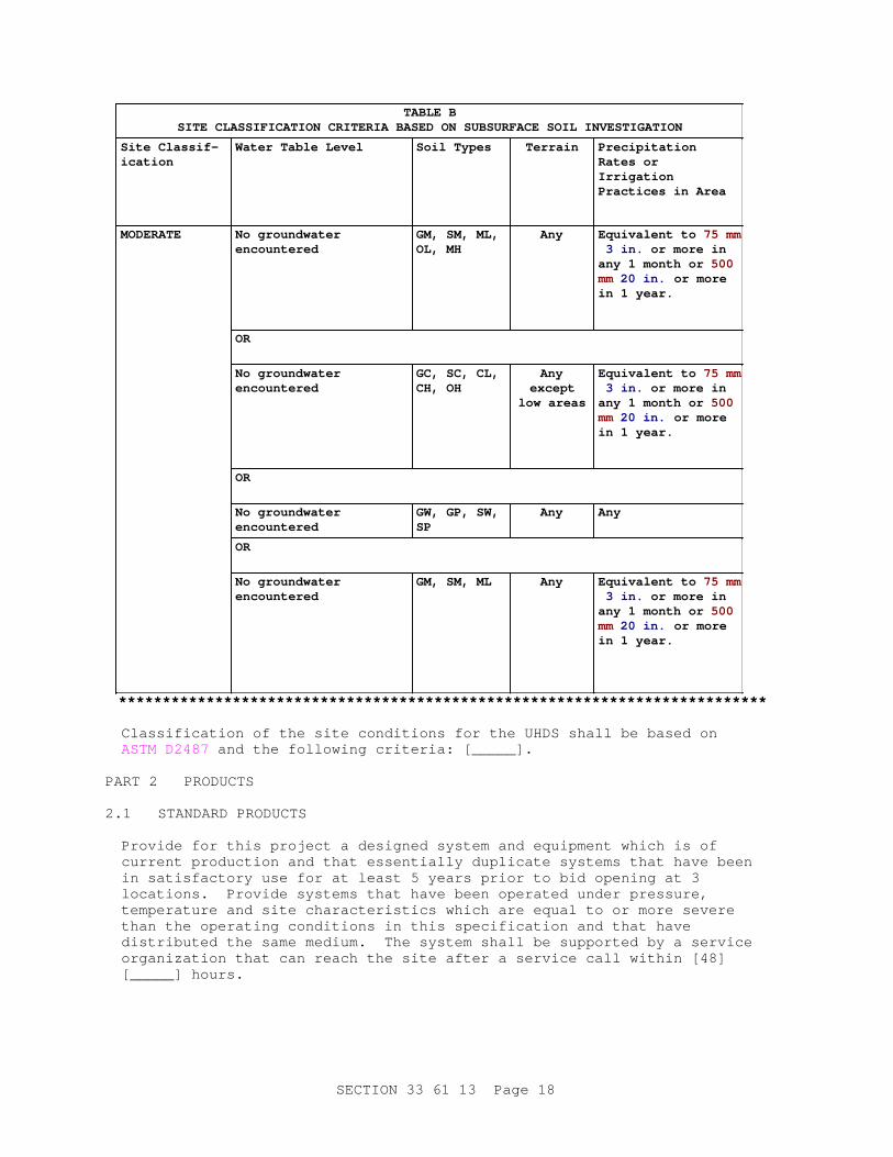
TABLE BSI TE CLASSI FI CATI ON CRI TERI A BASED ON SUBSURFACE SOI L I NVESTI GATI ON
Si t e Cl assi f -ication
Wat er Tabl e Level Soi l Types Terrain Precipitation Rat es or Irrigation Pr act i ces i n Ar ea
MODERATE No gr oundwat er encountered
GM, SM, ML, OL, MH
Any Equi val ent t o 75 mm 3 i n. or mor e i n any 1 mont h or 500 mm 20 i n. or mor e i n 1 year .
OR
No gr oundwat er encountered
GC, SC, CL, CH, OH
Anyexcept
l ow ar eas
Equi val ent t o 75 mm 3 i n. or mor e i n any 1 mont h or 500 mm 20 i n. or mor e i n 1 year .
OR
No gr oundwat er encountered
GW, GP, SW, SP
Any Any
OR
No gr oundwat er encountered
GM, SM, ML Any Equi val ent t o 75 mm 3 i n. or mor e i n any 1 mont h or 500 mm 20 i n. or mor e i n 1 year .
**************************************************************************
Classification of the site conditions for the UHDS shall be based on ASTM D2487 and the following criteria: [_____].
PART 2 PRODUCTS
2.1 STANDARD PRODUCTS
Provide for this project a designed system and equipment which is of current production and that essentially duplicate systems that have been in satisfactory use for at least 5 years prior to bid opening at 3 locations. Provide systems that have been operated under pressure, temperature and site characteristics which are equal to or more severe than the operating conditions in this specification and that have distributed the same medium. The system shall be supported by a service organization that can reach the site after a service call within [48] [_____] hours.
SECTION 33 61 13 Page 18

2.2 FACTORY FABRICATED, DIRECT-BURIED DDT SYSTEMS
2.2.1 DDT Steam and High Temperature Hot Water Carrier Pipes
Requirements shall be in accordance with paragraph HEAT DISTRIBUTION PIPING.
2.2.2 DDT Condensate Carrier Pipes
Carrier piping for condensate return systems shall be steel, schedule 80. Pipe requirements shall be in accordance with paragraph HEAT DISTRIBUTION PIPING. Condensate carrier pipes shall not be located in conduit casings which contain steam pipes or any other piping.
2.2.3 DDT Carrier Pipe Insulation
Carrier pipe insulation shall conform to minimum thicknesses and type listed in Tables 1 and 2 as required for temperature specified under paragraph Rated Characteristics.
2.2.4 Insulation Banding and Scrim
Stainless steel bands and clips, at least 13 mm 1/2 inch wide, conforming to ASTM A167 (304 stainless steel), at a maximum spacing of 460 mm 18 inches shall be used over the scrim to secure the insulation onto the carrier pipe; a minimum of 2 bands shall be used for each 1300 mm 4 foot section of insulation. Scrim shall be vinyl-coated fiberglass with 18 x 16 mesh (number of filaments per 25 mm 1 inch ) and made of 0.335 mm 0.013 inch diameter vinyl-coated fibrous glass yarn.
2.2.5 Casing
Casing shall be smooth-wall steel, electric resistance spiral welded, conforming to ASTM A134/A134M , ASTM A135/A135M , or ASTM A139/A139M and the values tabulated below. Eccentric connectors shall be provided between casing sections as needed to provide drainage of casing section between manholes and between manholes and buildings.
Casing Diameter (mm) (inches) Minimum Thickness (mm) (inch)
150 - 660 6 - 26 6.35 0.250
675 - 900 27 - 36 6.35 0.250
940 - 1050 37 - 42 6.35 0.250
1170 46 6.35 0.250
2.2.6 Casing End Plates, Vents, and Drains
**************************************************************************NOTE: Desi gner must accommodat e 25 mm 1 i nch vent pi pe i n t he desi gn of t he manhol e.
**************************************************************************
End plates shall be made of ASTM A36/A36M steel, minimum thickness 13 mm 1/2 inch for conduit pipe sizes above 300 mm 12 inches and 9.5 mm 0.375
SECTION 33 61 13 Page 19

inches for conduit pipe sizes 300 mm 12 inches and less. A 25 mm 1 inch ASTM A53/A53M, Sch 40, galvanized vent riser pipe shall be provided on end plate vent opening. Vent pipe shall extend to top of manhole and terminate 300 mm 12 inches above grade with a 180 degree bend. A 25 mm 1 inch drain shall be provided at the bottom and vent at the top. Brass plugs and half coupling, constructed with welded steel and welded to the end plate, shall be furnished; drains shall be plugged; vents shall not be plugged.
2.2.7 Air Space
Continuous 25 mm 1 inch minimum air space shall be provided between carrier pipe insulation and casing.
2.2.8 Casing Coating
Coating shall be rated by manufacturer for continuous service for at least 25 years at temperatures of 110 degrees C 230 degrees F . Coating shall be applied in accordance with the coating manufacturer's instructions, shall be factory inspected for holidays and repaired as necessary.
2.2.8.1 Fusion-Bonded Epoxy
Casing coating shall be fusion-bonded epoxy, minimum thickness 1 mm 0.04 inches .
2.2.8.2 Urethane Elastomer
Coating shall be urethane elastomer, minimum thickness 1 mm 0.04 inches .
2.2.9 Coating of End Plates and Conduit Extending into Manholes
End plates and conduit extending into manholes shall be coated with a zinc-rich coating conforming to AASHTO M 300 Type IA, except that volatile organic compounds shall not exceed 0.34 kg/L 2.8 pounds/gallon . The zinc-rich coating shall be applied in accordance with the coating manufacturer's requirements including surface preparation. No additional top coat shall be applied.
2.2.10 Carrier Pipe Guides
Carrier pipe guides shall be spaced 3 m 10 feet on centers maximum, no more than 1.5 m 5 feet from pipe ends, with a minimum of 3 guides per elbow section. Guides shall be designed to allow thermal expansion without damage, to provide proper pipe guiding, and to allow horizontal movement in 2 directions as required at expansion loops and bends. Design of supports shall permit flow of water through the support. Pipe insulation shall extend through the pipe guides and be protected by steel sleeves. Design of guides shall negate metal-to-metal contact between the casing and the carrier pipe. Insulation or non-metallic material used to ensure no metal-to-metal contact shall not be compressed by the weight of the carrier pipe when full of water.
2.2.11 Anchor Plates
Anchor plate shall be ASTM A36/A36M steel, welded to carrier pipe and casing, 13 mm 1/2 inch minimum thickness, with passages for air flow and water drainage thru the annular air space in the system. Exterior surface of the anchor plate shall be coated with the same coating material as the
SECTION 33 61 13 Page 20

casing.
2.2.12 Field Connection of Casing Sections
Field connection of casing shall be made using a compatible steel section, welded to casing sections, coated on all surfaces with UHDS manufacturer's coating field repair compound, and covered with a 1.3 mm 0.05 inch minimum thickness polyethylene shrink sleeve designed for a service temperature exceeding 80 degrees C 176 degrees F .
2.2.13 Manufacturer's Identification
Embossed brass or stainless steel tag, hung by brass or stainless steel chain at each end of each conduit or insulated piping in the manholes and buildings, shall be provided. The tag shall identify UHDS manufacturer's name, date of installation, Government contract number, and manufacturer's project number.
2.3 FACTORY FABRICATED, DIRECT-BURIED WSL SYSTEM
**************************************************************************NOTE: Cont act HQ bef or e al l owi ng t hi s syst em t o be i n t he cont r act .
**************************************************************************
2.3.1 WSL Steam and Carrier Pipes
Pipe material requirements shall be in accordance with paragraph HEAT DISTRIBUTION PIPING. The pipe shall be steel with the ends machined and metallized to provide a satisfactory sealing surface for the sealing rings. The metallizing shall be a high nickel alloy applied to an excess thickness and then machined to the required OD.
2.3.2 WSL Condensate Carrier Pipes
Carrier piping for condensate return systems shall be steel, schedule 80. Pipe requirements shall be in accordance with paragraph HEAT DISTRIBUTION PIPING. Condensate piping shall not be located in casings which contain any other piping.
2.3.3 Casing for Steam and Condensate
The casing shall be reinforced thermosetting resin plastic (RTRP) piping manufactured by the filament winding process. The casing pipe shall be wound to meet ASTM D2310 classification RTRP and ASTM D2996. The resin shall be a polyester isothalic resin. The outer surface shall be coated with a pigmented, protected resin containing a paraffinated wax and ultraviolet inhibitors. Casing thickness shall be as follows:
Carrier Pipe Size (mm) (Inches) Caasing Thickness (mm) (Inches)
50 2 5 0.185
80 3 5 0.185
100 4 5 0.185
SECTION 33 61 13 Page 21

Carrier Pipe Size (mm) (Inches) Caasing Thickness (mm) (Inches)
150 6 6.5 0.250
200 8 6.5 0.250
250 10 6.5 0.250
300 12 6.5 0.250
2.3.4 Pipe Coupling, Steam
Coupling shall be of a multi-stage seal designed to accommodate the expansion and contraction of the system in the coupling. Couplings shall be of corrosion resistant materials capable of handling the design characteristics of the system listed in paragraph Rated Characteristics. The annular seals and carrier pipe ends shall be specifically designed to protect the seals and resist abrasion due to lateral loads in the system.
2.3.5 Pipe Coupling, Condensate
Coupling shall be a single stage seal design to accommodate the expansion and contraction of the adjacent pipes. Coupling shall be of corrosion resistant materials capable of handling the design characteristics of the system listed in paragraph Rated Characteristics. The annular seals and carrier pipe ends shall be specifically designed to protect the seals and resist abrasion due to lateral loads in the system.
2.3.6 WSL Carrier Pipe Insulation
Insulation shall conform to minimum thicknesses and type listed for WSL systems in Tables 1 and 2 as required for temperature in carrier pipe. Insulation shall consist of an inner layer of high temperature calcium silicate and an outer layer of polyurethane foam.
2.3.6.1 Calcium Silicate for Steam Systems
The calcium silicate insulation shall be a hydrous material satisfactory for temperatures to 650 degrees C 1200 degrees F . Calcium silicate insulation shall conform to ASTM C533. The physical properties shall be as follows:
a. Density (dry): 208 kg/cubic meter 13 pcf (minimum).
b. Compressive Strength to produce 5 percent compression: 1723 kPa 250 psi (For 37 mm 1.5 inch thick sample).
c. Maximum linear shrinkage after 24 hour soaking period at 650 degrees C 1200 degrees F : 1.1 percent
d. Maximum Thermal Conductivity k: k = W/(meter*K) k = BTU-IN/HR-FT2-DEG.F) . Where k varies with temperature as shown:
SECTION 33 61 13 Page 22
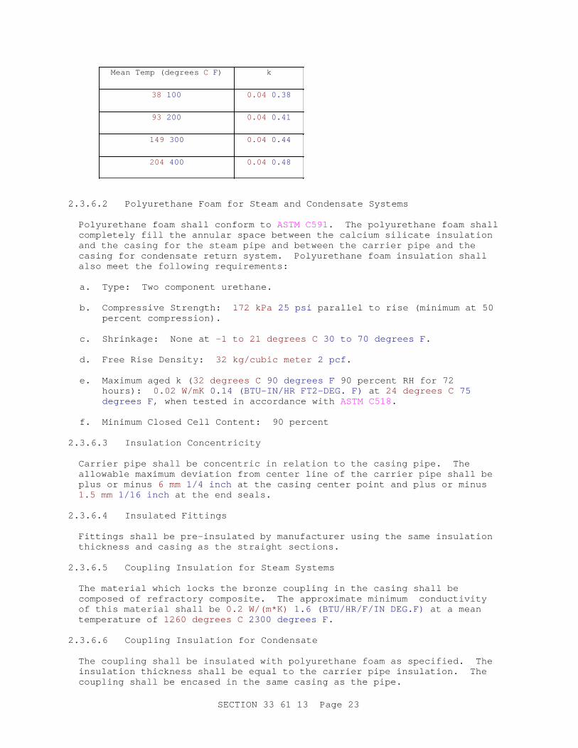
Mean Temp (degrees C F ) k
38 100 0.04 0.38
93 200 0.04 0.41
149 300 0.04 0.44
204 400 0.04 0.48
2.3.6.2 Polyurethane Foam for Steam and Condensate Systems
Polyurethane foam shall conform to ASTM C591. The polyurethane foam shall completely fill the annular space between the calcium silicate insulation and the casing for the steam pipe and between the carrier pipe and the casing for condensate return system. Polyurethane foam insulation shall also meet the following requirements:
a. Type: Two component urethane.
b. Compressive Strength: 172 kPa 25 psi parallel to rise (minimum at 50 percent compression).
c. Shrinkage: None at -1 to 21 degrees C 30 to 70 degrees F .
d. Free Rise Density: 32 kg/cubic meter 2 pcf .
e. Maximum aged k ( 32 degrees C 90 degrees F 90 percent RH for 72 hours): 0.02 W/mK 0.14 (BTU-IN/HR FT2-DEG. F) at 24 degrees C 75 degrees F , when tested in accordance with ASTM C518.
f. Minimum Closed Cell Content: 90 percent
2.3.6.3 Insulation Concentricity
Carrier pipe shall be concentric in relation to the casing pipe. The allowable maximum deviation from center line of the carrier pipe shall be plus or minus 6 mm 1/4 inch at the casing center point and plus or minus 1.5 mm 1/16 inch at the end seals.
2.3.6.4 Insulated Fittings
Fittings shall be pre-insulated by manufacturer using the same insulation thickness and casing as the straight sections.
2.3.6.5 Coupling Insulation for Steam Systems
The material which locks the bronze coupling in the casing shall be composed of refractory composite. The approximate minimum conductivity of this material shall be 0.2 W/(m*K) 1.6 (BTU/HR/F/IN DEG.F) at a mean temperature of 1260 degrees C 2300 degrees F .
2.3.6.6 Coupling Insulation for Condensate
The coupling shall be insulated with polyurethane foam as specified. The insulation thickness shall be equal to the carrier pipe insulation. The coupling shall be encased in the same casing as the pipe.
SECTION 33 61 13 Page 23

2.3.7 Manufacturer's Identification
Provide an embossed brass tag hung by a brass chain, or a stainless steel tag hung by a stainless steel chain, at each end of each casing or insulated piping in the manholes and buildings. The tags shall identify UHDS manufacturer's name and date of installation.
2.3.8 End Seals
Each preinsulated section of piping shall completely seal the insulation, providing a permanent water and vapor seal at each end. Preinsulated factory fabricated sections of piping modified in the field shall be provided with an end seal which is equivalent to the end seals furnished with the preinsulated section of piping. Tests shall be conducted by the UHDS manufacturer to demonstrate that casings, couplings and end seals are capable of resisting penetration of water into the casing and insulation under rated conditions. The tests shall be performed on each type of pre-fabricated system to be furnished, and the test results shall be verified by an independent testing laboratory. The steam and condensate return systems shall be tested and certified in accordance with paragraph Assembly Test of WSL Systems for Condensate Return Service.
2.3.8.1 End Seals for Steam Service
End seals shall be elastomer-ring type designed and dimensioned to fit in the annular space between the casing and the carrier pipe. Tape used for covering field repair joints shall be multi-polymer alloy film type and shall be compatible with synthetic elastomeric tape, suitable for cold application.
2.3.8.2 End Seals for Condensate Return Service
End seals provided shall be one of the following types:
a. Carrying the outer casing over tapered pipe insulation ends and extending it to the carrier pipe. Sufficient surface bonding area shall be provided between the casing and the carrier pipe.
b. Using specially designed molded caps made of polyethylene or rubber of standard manufactured thickness. A minimum 40 mm 1-1/2 inch surface bonding area shall be provided between the cap and both the casing and carrier pipe.
c. Using elastomer-ring end seals designed and dimensioned to fit in the annular space between the casing and the carrier pipe.
d. Using a waterproof mastic seal vapor barrier over the exposed insulation ends.
e. Shrink sleeves.
2.3.9 Test of WSL Systems for Steam Service
The tests shall demonstrate that the WSL system will operate successfully for 25 years under typical operating conditions. The tests shall be conducted in both a dry and wet environment. The WSL system shall be as described in the manufacturer's brochure. The testing program described below shall be conducted at the expense of the WSL system manufacturer.
SECTION 33 61 13 Page 24

Tests shall be witnessed and verified by an independent testing laboratory. The entire pre-insulated test section shall be hydrostatically tested, with water, to 2600 kPa 375 psig (1.5 times the rated pressure) before and after temperature cycling. The tests shall be conducted in a dry environment for 60 cycles followed by a test in a wet environment for 60 cycles for a total of 120 cycles. The test in the wet environment demonstrates resistance to ground water infiltration. All tests shall be conducted on 1 test section and all testing shall be completed in 1 time period (approximately 6 weeks) and the 120 testing cycles shall be continuous except for weekend time periods.
2.3.9.1 Apparatus
A curved bottom test tank at least 3.7 m 12 feet long, 0.8 m 32 inches wide, 0.8 m 32 inches deep shall be used. The tank shall be fitted with a gasketed and bolted cover to pressurize the tank to 60 kPa 8.67 psig . The tank shall have a drain at the lowest point and a vent at the highest point. Manhole entrance sleeves (i.e. wall sleeves through the ends of the tank to simulate manhole entries in actual field conditions) shall be centrally located on each end of the tank. Auxiliary equipment shall include: Steam supply with sufficient capacity to satisfy testing requirements, makeup water tank and pump, and a means for continuously recording temperatures and pressures at needed locations. Thermocouples shall be used to record temperatures and pressure at the following points:
a. Carrier pipe at tank inlet (in thermowell).
b. Casing at mid-point in pipe length (on casing).
c. Casing at anchor point (above FRP overwrap on plate).
d. Casing at field joint (repair, on casing).
e. Casing at coupling mid-point (on casing).
f. End seal flange at coupling (on elastomer).
g. Outer edge of new end plate (at steel plate and FRP wrap).
h. Carrier pipe at specimen outlet end (in thermowell).
i. Interface of calcium-silicate and polyurethane insulations.
j. Interface of calcium-silicate and polyurethane insulations.
k. Carrier pipe internal pressure, at inlet to test specimen.
l. Pressure at test tank.
Surface thermocouples shall be epoxied to the surface of the casing. The calibration of the thermocouples shall be checked and recorded prior to installation and the recorder shall record within 0.06 degree C 0.1 degree Fresolution.
2.3.9.2 Test Section
A 100 mm 4 inch steel carrier pipe test section consisting of 8 m 27 feet of pre-insulated pipe meeting specified materials and design requirements shall be provided. Approximately 3.7 m 12 feet of the test section shall
SECTION 33 61 13 Page 25
be encased within the tank as described below. The test section within the tank shall consist of an expansion coupling, field repair joint, anchor plate, anchor block and end seals. The test section shall be installed (as directed) on at least 280 mm 11 inches of firmly tamped sand. Sand shall surround the casing, and top surface of the sand shall not be any farther than 100 mm 4 inches from the top of the tank. The test section shall be anchored to the tank wall at one end and the building floor at the other end on the portion of the pipe external to the tank. The expansion coupling shall be misaligned by 1.5 degrees in the horizontal plane. Sand ( 118 mL 4 fluid oz ) shall be introduced into the carrier pipe and disbursed throughout the test loop at startup.
2.3.9.3 Resistance to Water Damage and Joint Leakage
This test shall simulate the operation of the WSL system to assure the system will provide successful service life thru its expected life span. The system shall be tested in steam service by cycling for an extended period of time, as described below. System performance shall be deemed successful if there is no joint leakage, deformation of the casing, deterioration of the end seals, or any other deleterious effects.
a. The piping system shall be subjected to 60 cycles of steam introduced into the system while at ambient temperature 38 degrees C 100 degrees F up to a temperature of 207 degrees C 406 degrees F (as measured at the core pipe at the tank inlet and tank outlet) and back to ambient temperature. The system shall be held at 207 degrees C 406 degrees F minimum for a minimum of 30 minutes, each cycle. This cycling shall continue for 60 cycles in dry sand followed by 60 cycles in a saturated environment. The reduction in temperature to 38 degrees C 100 degrees F shall occur naturally with no artificial means of cooling used.
b. Results shall conform to paragraph Criteria for Satisfactory Results and Reporting.
2.3.9.4 Resistance to Mechanical or Structural Damage
This test shall simulate loads induced by truck traffic over pipe, which may occur under actual operating conditions. This test shall be conducted commencing with the 41st cycle of the Resistance to Water Damage and Joint Leakage test and continue through the 60th cycle. Other aspects of the Resistance to Water Damage and Joint Leakage test shall continue simultaneously with this test.
2.3.9.4.1 Apparatus
Same as for apparatus used in Resistance to Ground Water Infiltration test with the addition of a 96 kPa 2000 psf loading device. A hydraulic jack shall be used to apply the test pressure against a 500 by 500 mm 18 by 18 inch plate bearing on the sand directly over the coupling in the tank.
2.3.9.4.2 Procedure
A steady and constant vertical load of 96 kPa 2000 psf shall be applied to the plate for 14 days during the test. The test section shall be installed as in the Resistance to Ground Water Infiltration test. During the 14 day loading period, steam shall be circulated through the carrier pipe alternately at ambient and 207 degrees C 406 degrees F as in earlier test.
SECTION 33 61 13 Page 26
2.3.9.4.3 Results
Requirements shall be in accordance with paragraph Criteria for Satisfactory Results and Reporting.
2.3.9.5 Resistance to Ground Water Infiltration
This test shall be the wet environment test conducted during the second 3 weeks (61st to 120th cycles) of the test period to show that the WSL system will resist the penetration of ground water into the system.
2.3.9.5.1 Apparatus
Same as for basic apparatus used in Resistance to Water Damage and Joint Leakage phase test, plus the following:
a. One 200 L 50 gallon water reservoir with a 0 to 206 kPa 0 to 30 psig pressure gauge and compressed air connection.
b. Provisions to introduce pressurized red dye into the curved bottom test tank. The water/dye solution shall be mixed to a concentration in accordance with the dye manufacturer's recommendation for maximum detectability.
c. One pressure tank with 0 to 206 kPa 0 to 30 psig static pressure gauge.
2.3.9.5.2 Procedure
This phase shall start on the 61st cycle and continue until the 120th cycle. The test section of pipe shall be the same test segment used in the previous tests. The tank cover shall be bolted in place and the Resistance to Ground Water Infiltration test shall begin. The water/dye source shall be attached to the fill fitting and a surge tank shall be attached to the vent with a tee fitting. The pressure tank shall have a 0 to 206 kPa 0 to 30 psig static pressure gauge attached. The other branch of the tee fitting shall employ a shut-off valve. With the shut-off valve open, the water/dye mixture shall be admitted into the tank through the fill fitting until the tank is full and water/dye runs freely from the open valve. The valve shall be closed and the filling shall continue until the pressure reaches 60 kPa 8.67 psig . The tank pressure shall be maintained throughout the test period. Steam shall be circulated through the carrier pipe and cycled from ambient to 207 degrees C 406 degrees F as in the previous test. At the end of the test, the pressure shall be relieved by opening the vent valve and the water/dye shall be drained from the tank through the drain fitting.
2.3.9.5.3 Results
Requirements shall be in accordance with paragraph Criteria for Satisfactory Results and Reporting.
2.3.9.6 Criteria for Satisfactory Results and Reporting
2.3.9.6.1 Reporting
Logs of times and temperature shall be recorded to assure compliance with test requirements and procedures. Complete photographic documentation of the construction and operation of the test facility, as well as the piping
SECTION 33 61 13 Page 27

system components before and after testing, shall be produced. Data shall be analyzed to assure complete compliance with test objectives.
2.3.9.6.2 Drawing
A drawing showing details of the test apparatus and test specimen shall be provided.
2.3.9.6.3 Resistance to Water Damage and Joint Leakage Test
Joints and end seals shall be removed for examination, immediately upon completion of all test cycles. Successful results shall show that steam has not leaked out of the carrier pipe and that the components show no signs of deterioration.
2.3.9.6.4 Resistance to Mechanical or Structural Damage Test
The casing shall not be damaged or deformed enough to impair functioning of the system. The casing shall not be ruptured and shall not be deformed more than 25 mm 1 inch in any direction. In casings with pipe anchors, there shall be no separation between the casing and the pipe anchor interface.
2.3.9.6.5 Resistance to Ground Water Infiltration Test
The water/dye solution shall not have entered the insulation. This shall be determined by removing and inspecting all joints and seals for dye penetration at the end of the test. Results will be deemed successful if no solution is evident in the insulation.
2.3.9.6.6 Evidence of Test Results
After completion of all tests, the test apparatus shall be dismantled for visual inspection of all critical components subjected to the heat cycling, water infiltration and loading tests. All parts will be examined thoroughly for any detrimental affects. Examinations identified shall be conducted. Log sheets, test data and color photographs shall be kept on file and made available as required to document and substantiate compliance to the test requirements.
2.3.9.6.7 Report
Submit a report from the independent testing agency. The report must include the laboratory analysis of the condition of the test section and attest that the testing conditions were followed.
2.3.10 Test of WSL Systems for Condensate Return Service
Submit test reports in booklet form showing all factory and field tests performed to prove compliance with the specified performance criteria, upon completion and testing of the installed system. Testing and certification procedures by an independent testing laboratory shall demonstrate that casings and end seals are capable of resisting penetration of water into the casing and insulation. The test shall be performed on the type of prefabricated system to be furnished. If more than one type of prefabricated system is to be used, the tests shall be performed on each type. The test shall consist of hot and cold cycle testing followed by immersion in a water filled chamber with a head pressure. The hot and cold cycle testing shall consist of 14 days of
SECTION 33 61 13 Page 28
temperature cycling.
a. A fluid with a temperature of 5 degrees C 40 degrees F shall circulate through the carrier pipe, alternating every 24 hours with a fluid with a temperature of 95 degrees C 200 degrees F circulating through the carrier pipe for a low temperature hot water or dual temperature service, or 24 degrees C 75 degrees F for a chilled water service.
b. While the hot and cold cycle test is being performed, the test sample shall be either buried or encased in dry bedding sand with a minimum of 300 mm 12 inches of sand all around the test sample. The carrier pipe size of the test sample shall be 75 mm 3 inches in diameter and shall be restrained during the test period. The insulation thickness shall not exceed the maximum thickness provided for the piping in the project.
c. Transition time for temperature cycle testing shall not exceed 15 minutes in going from cold to hot and 30 minutes in going from hot to cold. The fluid in the carrier pipe may be water, oil or heat transfer fluid. Following the hot and cold cycling test, the test sample shall be immersed in a water filled chamber. The pressure on the highest point of the test sample shall not be less than 60 kPa 20 feet of water head pressure subjected over the entire length of the 2.4 m 8 foot test sample of prefabricated pipe.
d. The water shall contain a dye penetrant, which shall be used to check for end seal leakage. The pressure in the chamber shall be held for not less than 48 hours. Upon completion of this pressure test, the test sample shall be cut open. With the use of a light that will readily show the presence of the dye that was in the water, the test sample shall be inspected. Evidence of the dye inside the test sample shall indicate that the end seal is not acceptable and cannot be certified.
2.4 WATER SPREAD LIMITING POURED-IN-PLACE INSULATION (PIPI) SYSTEM
2.4.1 PIPI Steam and High Temperature Hot Water Carrier Pipes
Requirements shall be in accordance with paragraph HEAT DISTRIBUTION PIPING.
2.4.2 PIPI Condensate Carrier Pipes
Carrier piping for condensate return systems shall be steel, schedule 80. Pipe requirements shall be in accordance with paragraph HEAT DISTRIBUTION PIPING.
2.4.3 PIPI Carrier Pipe Insulation
Carrier pipe PIPI shall conform to minimum thickness and type listed in Table 3 as required for temperature specified under paragraph Rated Characteristics.
2.4.4 Poured-in-Place Insulation - Physical Properties
The poured-in-place insulation shall consist of calcium carbonate powder chemically modified to be hydrophobic with no particles exceeding 1 mm in any dimension. The installed density shall fall in the range of 960 to 992 kg/cubic meter 40 to 62 lb/cubic foot when tested in accordance with
SECTION 33 61 13 Page 29

ASTM D1895. Perform additional product testing at the identified installed density in accordance with ASTM C177.
2.4.5 Poured-in-Place Insulation - Thermal Properties
The thermal conductivity of the PIPI shall not exceed 0.083 W/mK 0.58 Btu-in/hr-square foot-degree F at 37.8 degrees C 100 degrees F , and 0.099 W/mK 0.68 Btu-in/hr-square foot-degree F at 149 degrees C 300 degrees F , when tested in accordance with ASTM C177.
2.4.6 Poured-in-Place Insulation - Electrical Properties
The electrical resistivity of the PIPI shall not be less than 1 by 10 to the 12th power ohm-cm.
2.4.7 PIPI System Piping Anchors, Supports, and Guides
The design and location of pipe anchors, pipe supports, pipe guides, and expansion cushions shall be in compliance with the most recent design manual available from the PIPI manufacturer.
2.4.8 PIPI Envelope Penetrations
The design of penetrations through the PIPI envelope shall be in compliance with the most recent design manual available from the PIPI manufacturer. All pipe anchors, pipe supports, pipe guides and manhole walls that come in contact with the PIPI shall be coated with a mastic compound. For pipe service temperatures up to 204 degrees C 400 degrees F the mastic compound shall be bitumastic coal tar. For pipe service temperatures in excess of 204 degrees C 400 degrees F silicone grease shall be used.
2.5 PIPE INSULATION TYPE AND MINIMUM THICKNESS
**************************************************************************NOTE: Del et e i nappl i cabl e col umns i n Tabl es 1 and 2.
**************************************************************************
Comply with EPA requirements in accordance with Section 01 33 29 SUSTAINABILITY REPORTING. Materials containing asbestos will not be permitted. The minimum thickness of insulation for the heat distribution system shall be in accordance with Tables 1 and 2 in which the insulations listed have passed the 96 hour boiling water test.
SECTION 33 61 13 Page 30

TABLE 1MINIMUM PIPE INSULATION THICKNESS (mm) (Inches)
For Steam (100 to 2,800 kPa (gage)) (16 to 408 psig) and High Temperature Hot WaterSupply and Return (120 to 230 degrees C) (250 to 450 degrees F)
INSULATIONS for Drainable/Dryable Systems INSULATIONS for OtherPre-Engineered Systems
Nominal PipeDiameter (mm)
(inches)
Delta Theromo-12Super Caltemp
MPT-PFMPT-PC
CalciumSilicate
WSLPolyurethane
251.0 652.5 100 4.0 502.0 N/A N/A
401.5 652.5 100 4.0 502.0 N/A N/A
502.0 853.5 110 4.5 652.5 N/A N/A
652.5 853.5 110 4.5 652.5 N/A N/A
803.0 100 4.0 125 5.0 753.0 251.0 +31+1.23
100 4.0 100 4.0 125 5.0 753.0 251.0 +31+1.23
125 5.0 100 4.0 125 5.0 753.0 N/A N/A
150 6.0 110 4.5 135 5.5 853.5 351.5 +34+1.34
200 8.0 110 4.5 135 5.5 853.5 502.0 +30+1.21
250 10.0 125 5.0 150 6.0 100 4.0 652.5 +33+1.31
300 12.0 125 5.0 150 6.0 100 4.0 502.0 +32+1.29
350 14.0 125 5.0 150 6.0 100 4.0 N/A N/A
400 16.0 125 5.0 150 6.0 100 4.0 N/A N/A
450 18.0 125 5.0 150 6.0 100 4.0 N/A N/A
1) Delta is available from Rockwool in Leeds, Alabama.
2) MPT is available from Mineral Products of Texas in Houston, TX
3) Thermo-12 and Super Caltemp are available from Johns Manville in Denver, Colorado.
SECTION 33 61 13 Page 31

TABLE 1AMINIMUM PIPI THICKNESS (mm) (Inches)
For Steam (100 to 2,800 kPa (gage)) (16 to 408 psig) and High Temperature HotWater Supply and Return (120 to 230 degrees C) (250 to 450 degrees F)
Nominal PipeDiameter (mm)
(inches)
Sides and Bottom Between Pipes Above Pipes
251.0 100 4.0 502.0 125 5.0
401.5 100 4.0 502.0 125 5.0
502.0 100 4.0 502.0 125 5.0
652.5 100 4.0 502.0 125 5.0
803.0 100 4.0 502.0 125 5.0
100 4.0 125 5.0 502.0 150 6.0
125 5.0 125 5.0 753.0 175 7.0
150 6.0 150 6.0 753.0 175 7.0
200 8.0 150 6.0 100 4.0 200 8.0
250 10.0 150 6.0 100 4.0 200 8.0
300 12.0 175 7.0 100 4.0 250 10.0
350 14.0 175 7.0 100 4.0 250 10.0
400 16.0 200 8.0 125 5.0 250 10.0
450 18.0 200 8.0 125 5.0 250 10.0
TABLE 2MINIMUM PIPE INSULATION THICKNESS (mm) (Inches) CONDENSATE RETURN
INSULATIONS for Drainable/Dryable Systems INSULATIONS forOther
Pre-EngineeredSystems
Nominal PipeDiameter (mm)
(inches)
Delta Theromo-12Super Caltemp
MPT-PFMPT-PC
Polyurethane
251.0 502.0 753.0 351.5 N/A
401.5 502.0 753.0 351.5 N/A
SECTION 33 61 13 Page 32
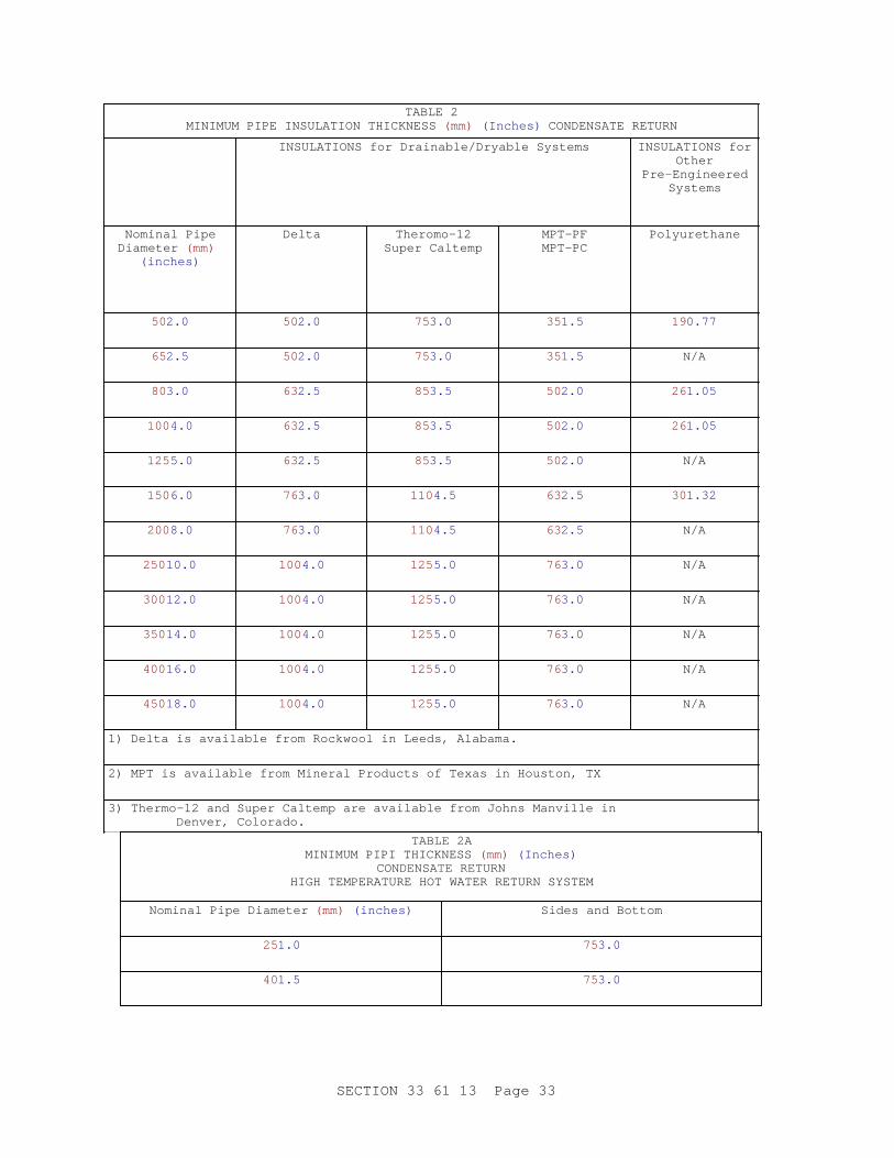
TABLE 2MINIMUM PIPE INSULATION THICKNESS (mm) (Inches) CONDENSATE RETURN
INSULATIONS for Drainable/Dryable Systems INSULATIONS forOther
Pre-EngineeredSystems
Nominal PipeDiameter (mm)
(inches)
Delta Theromo-12Super Caltemp
MPT-PFMPT-PC
Polyurethane
502.0 502.0 753.0 351.5 190.77
652.5 502.0 753.0 351.5 N/A
803.0 632.5 853.5 502.0 261.05
100 4.0 632.5 853.5 502.0 261.05
125 5.0 632.5 853.5 502.0 N/A
150 6.0 763.0 110 4.5 632.5 301.32
200 8.0 763.0 110 4.5 632.5 N/A
250 10.0 100 4.0 125 5.0 763.0 N/A
300 12.0 100 4.0 125 5.0 763.0 N/A
350 14.0 100 4.0 125 5.0 763.0 N/A
400 16.0 100 4.0 125 5.0 763.0 N/A
450 18.0 100 4.0 125 5.0 763.0 N/A
1) Delta is available from Rockwool in Leeds, Alabama.
2) MPT is available from Mineral Products of Texas in Houston, TX
3) Thermo-12 and Super Caltemp are available from Johns Manville in Denver, Colorado.
TABLE 2AMINIMUM PIPI THICKNESS (mm) (Inches)
CONDENSATE RETURNHIGH TEMPERATURE HOT WATER RETURN SYSTEM
Nominal Pipe Diameter (mm) (inches) Sides and Bottom
251.0 753.0
401.5 753.0
SECTION 33 61 13 Page 33
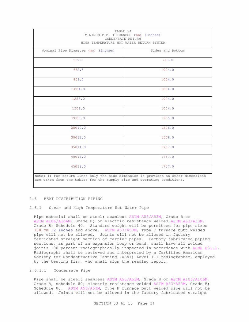
TABLE 2AMINIMUM PIPI THICKNESS (mm) (Inches)
CONDENSATE RETURNHIGH TEMPERATURE HOT WATER RETURN SYSTEM
Nominal Pipe Diameter (mm) (inches) Sides and Bottom
502.0 753.0
652.5 100 4.0
803.0 100 4.0
100 4.0 100 4.0
125 5.0 100 4.0
150 6.0 100 4.0
200 8.0 125 5.0
250 10.0 150 6.0
300 12.0 150 6.0
350 14.0 175 7.0
400 16.0 175 7.0
450 18.0 175 7.0
Note: 1) For return lines only the side dimension is provided as other dimensions are taken from the tables for the supply size and operating conditions.
2.6 HEAT DISTRIBUTION PIPING
2.6.1 Steam and High Temperature Hot Water Pipe
Pipe material shall be steel; seamless ASTM A53/A53M, Grade B or ASTM A106/A106M , Grade B; or electric resistance welded ASTM A53/A53M, Grade B; Schedule 40. Standard weight will be permitted for pipe sizes 300 mm 12 inches and above. ASTM A53/A53M, Type F furnace butt welded pipe will not be allowed. Joints will not be allowed in factory fabricated straight section of carrier pipes. Factory fabricated piping sections, as part of an expansion loop or bend, shall have all welded joints 100 percent radiographically inspected in accordance with ASME B31.1 . Radiographs shall be reviewed and interpreted by a Certified American Society for Nondestructive Testing (ASNT) Level III radiographer, employed by the testing firm, who shall sign the reading report.
2.6.1.1 Condensate Pipe
Pipe shall be steel; seamless ASTM A53/A53M, Grade B or ASTM A106/A106M , Grade B, schedule 80; electric resistance welded ASTM A53/A53M, Grade B; Schedule 80. ASTM A53/A53M, Type F furnace butt welded pipe will not be allowed. Joints will not be allowed in the factory fabricated straight
SECTION 33 61 13 Page 34
section of the carrier pipe. Factory fabricated piping sections, as part of an expansion loop or bend shall have all welded joints 100 percent radiographically inspected in accordance with ASME B31.1 . Radiographs shall be reviewed and interpreted by an ASNT Certified Level III radiographer, employed by the testing firm, who shall sign the reading report.
2.6.1.2 Joints
Joints shall be butt-weld except socket-weld joints will be permitted for pipe sizes 50 mm 2 inches and smaller. Dye penetrant may be used in place of 100 percent radiographic inspection for pipe sizes 50 mm 2 inches and below. Location and elevation of all field joints shall be indicated on detailed design layout drawings. Split-ring welding rings may be used.
2.6.2 Fittings
Welds in factory fittings shall be radiographically inspected. Radiographs shall be reviewed and interpreted by a Certified ASNT Level III radiographer, employed by the testing firm, who shall sign the reading report. The Contracting Officer may review all inspection records, and if any welds inspected are found unacceptable in accordance with ASME B31.1 , the fitting shall be removed, replaced, and radiographically reexamined at no cost to the Government.
2.6.2.1 Butt-Welded
Fittings shall be steel; ASTM A234/A234M , Grade B or ASME B16.9 , same schedule as adjoining pipe. Elbows shall be long radius unless otherwise indicated. Tees shall be full size or reducing as required, having interior surfaces smoothly contoured. Split-ring welding rings may be used.
2.6.2.2 Socket-Welded
Fittings shall be forged steel ASME B16.11 ; 13,800 kPa 2000 pound class shall be used for pipe sizes 50 mm 2 inch and below. Dye penetrant inspection may be used in lieu of radiographic inspection of welded fittings for pipe sizes 50 mm 2 inches and below.
2.7 EXPANSION LOOPS AND BENDS
Stresses shall be less than the maximum allowable stress from the Power Piping Code ( ASME B31.1 ). Submit pipe-stress and system-expansion calculations for each expansion compensation elbow using a finite element computer generated 3 dimensional analysis, not later than [7 days] [_____] after notice to proceed. Demonstrate with calculations that pipe stresses from temperature changes are within the allowable requirements in ASME B31.1 and that the anchors and the guides will withstand the resultant forces. Detailed design layout drawings shall include all analysis node points. As a minimum, computer analysis results shall include node stresses, forces, moments and displacements. Calculations shall be stamped by a registered Professional Engineer in the employ of the UHDS manufacturer. Detailed design layout drawings and stress and anchor force calculations shall be provided for all loops and bends. Locations of all anchors, guides and supports shall be shown. The calculations shall be based on design characteristics (pressures and temperatures) specified for both the supply and return lines.
SECTION 33 61 13 Page 35
PART 3 EXECUTION
3.1 PREPARATION
3.1.1 Job Conditions
Phasing of [demolition and construction] [construction] shall be as shown on contract drawings.
3.1.2 Interruption of Existing Service
Submit schedule of proposed outages and interruptions of existing services, [14 days] [_____] in advance. Arrange, phase and perform work and provide temporary facilities, materials, equipment, and connections to utilities, to ensure adequate heat distribution service for existing installations at all times. Only necessary interruptions required for making connections will be permitted, and only at times when approval is obtained from the Contracting Officer. Set all interruptions to be [between the hours of [_____] and [_____]] [as approved by the Contracting Officer].
3.1.3 Grading
Unless otherwise shown on the contract drawings or the detailed design layout drawings, steam/condensate and high temperature hot water supply/return lines shall be graded uniformly downward not less than 40 mm in 10 meters 5.0 inches in 100 feet to the lower point of entry between manholes and/or building entries.
3.1.4 Connecting to Existing Work
**************************************************************************NOTE: Any connect i ons t o t he UHDS di st r i but i on wi l l onl y occur i n manhol es. Desi gner must ensur e t hat a t hor ough sur vey of t he abovegr ound and under gr ound condi t i ons i s per f or med. The cont r act dr awi ngs must i dent i f y al l pot ent i al i nt er f er ences or conf l i c t s.
**************************************************************************
Submit changes required to the UHDS design due to interferences or conflicts, upon realization of interferences or conflicts. Connect new work to existing work in a neat and workmanlike manner. Make connections only in manholes. Where an existing structure must be cut or existing utilities interfere, such obstructions shall be bypassed, removed, replaced or relocated, restored and repaired. Any changes required to the UHDS design as a result of interferences or conflicts shall be approved by the UHDS designer and the Contracting Officer. Work disturbed or damaged shall be replaced to its prior condition.
3.1.5 Coordination
The location of all items of equipment and work of all trades shall be coordinated. Operability and maintainability of the equipment and systems shall be maintained.
3.1.6 Variations
Any variations from the approved, detailed design layout drawings shall be submitted to the Contracting Officer for approval. Variations shall be
SECTION 33 61 13 Page 36

signed and sealed by the UHDS manufacturers' professional engineer responsible for the complete design of the UHDS.
3.2 DEMOLITION
**************************************************************************NOTE: Ensur e t hat Sect i on 02 41 00 DEMOLI TI ON AND DECONSTRUCTI ON i s i ncl uded i n pr oj ect speci f i cat i ons. Demol i t i on wor k shoul d be wel l def i ned i n t he dr awi ngs and speci f i cat i ons; phot ogr aphs shoul d be i ncl uded i n t he cont r act package, i f avai l abl e.
**************************************************************************
3.2.1 Demolition Procedures
Work shall be performed in accordance with requirements for phasing. Pipe, valves, fittings, insulation, and hangers, including the connection to the structure and any fastenings, shall be removed. Openings in manhole or building walls shall be sealed after removal of piping. Material and equipment removed shall become the property of the Contractor and shall be removed from Government property within 1 week and shall not be stored in operating areas. Flame cutting shall be performed with adequate fire protection facilities available as required by safety codes and Contracting Officer.
3.2.2 Asbestos Removal
**************************************************************************NOTE: Exi st i ng syst ems may i ncl ude asbest os cont ai ni ng mat er i al s. Pr ovi s i ons must be made f or an asbest os sur vey t o be per f or med and abat ement measur es t o be i ncl uded i n pr oj ect speci f i cat i on i f necessary.
**************************************************************************
Asbestos removal shall conform to Section 02 82 00 ASBESTOS REMEDIATION.
3.3 PIPE, PIPING JOINTS AND FITTINGS
3.3.1 Joint Preparation
Pipe and fittings shall be cleaned inside and outside before and after assembly. Dirt, scale, and other foreign matter shall be removed from inside the piping by use of a pipe swab or pipe pig before connecting pipe sections, valves, equipment or fittings. Eccentric connectors shall be used as needed between casing sections to provide drainage of casing section between manholes and between manholes and buildings.
3.3.2 Direction Changes
Changes in direction shall be made with factory-built reinforced fittings. Field-fabricated fittings and miters will not be permitted.
3.4 WELDING
Submit Certification of Acceptability of all welds made in the field, upon completion of the project. This certification shall consist of a letter, signed by an official of the independent testing firm or firms examining
SECTION 33 61 13 Page 37
welds, stating that all provisions of this specification have been complied with, and that all welds inspected radiographically have met the specified acceptability standards. The Contractor will be responsible for welding quality and shall:
a. Conduct tests of the welding procedures used in the work, determine the suitability of the procedures used, determine that the welds made will meet the required tests, and determine that the welding operators have the ability to make sound welds under standard conditions.
b. Comply with ASME B31.1 .
c. Perform all welding operations required for construction and installation of the heat distribution system.
3.4.1 Qualification of Welders
Rules of procedure for qualification of all welders and general requirements for fusion welding shall conform with the applicable portions of ASME B31.1 , and as outlined below.
3.4.2 Examining Welders
Examine each welder to determine the ability of the welder to meet the required qualifications. Welders shall be tested for welds in all positions, including welds with the axis horizontal (not rolled) and with the axis vertical. Each welder shall:
a. Weld only in positions in which they have qualified.
b. Identify welds with the specific code marking signifying name and number assigned.
3.4.3 Examination Results
Furnish a list of welder's names and corresponding code markings. Welders which fail to meet the prescribed welding qualifications shall be retested. Welders who fail the second test shall be disqualified for work on this project.
3.4.4 Beveling
Field and shop bevels shall be done by mechanical means or by flame cutting. Where beveling is done by flame cutting, surfaces shall be thoroughly cleaned of scale and oxidation just prior to welding.
3.4.5 Alignment
Split welding rings shall be used for field joints on carrier pipes above 50 mm 2 inches to assure proper alignment, complete weld penetration, and prevention of weld spatter reaching the interior of the pipe. Field joints 50 mm 2 inches and smaller shall be made with welding sockets.
3.4.6 Erection
Piping shall not be split, bent, flattened, or otherwise damaged before, during, or after installation. Where the pipe temperature falls to 0 degrees C 32 degrees F or lower, the pipe shall be heated to approximately 38 degrees C 00 degrees F for a distance of 300 mm 1 foot on each side of
SECTION 33 61 13 Page 38

the weld before welding, and the weld shall be finished before the pipe cools to 0 degrees C 32 degrees F .
3.4.7 Defective Welds
Defective welds shall be replaced and reinspected in accordance with ASME B31.1 . Repairing defective welds by adding weld material over the defect or by peening will not be permitted. Welders responsible for defective welds shall be tested for qualification.
3.4.8 Electrodes
Electrodes shall be stored in a dry, heated area, and shall be kept free of moisture and dampness during fabrication operations. Electrodes that have lost part of their coating shall not be used.
3.4.9 Radiographic Testing
An approved independent testing firm regularly engaged in radiographic testing shall perform radiographic examination of 100 percent of the field welds in the carrier piping of direct-buried systems in accordance with ASME B31.1 . The following shall be furnished: a set of films showing each weld inspected, a reading report evaluating the quality of each weld, and a location plan showing the physical location where each weld is to be found in the completed project, prior to installing casing field joints, backfilling and hydrostatic testing. All radiographs shall be reviewed and interpreted by a Certified American Society for Nondestructive Testing Level III radiographer, employed by the testing firm, who shall sign the reading report. The Contracting Officer may review all inspection records, and if any welds inspected are found unacceptable they shall be removed, rewelded, and radiographically reexamined at no cost to the Government.
3.5 HEAT DISTRIBUTION SYSTEM INSTALLATION
Submit a complete description of the design and assembly of the system, materials of construction and field installation instructions, not later than [21 days] [_____] prior to the start of field measurements. Include sufficient system details to show that the specified minimum insulation thickness has been met. A detailed design layout of the system (plan and elevation views) showing size, type, elevations and location of each component to be used in the system, the design and location of anchors, pipe guides, pipe supports, expansion loops, Z-bends, L-bends, end seals, leak plates, joint locations, pipe and insulation thickness and sizes, types, and movements, connection to manhole and building wall penetrations, and including, if applicable, details of transition point to aboveground or other type systems. Also, if applicable, type and details of the cathodic protection system to be used. Detailed design layout drawings shall be stamped by a registered Professional Engineer. The UHDS manufacturer's representative shall oversee the delivery, storage, installation and testing of the system. Work shall be in accordance with the requirements specified and with the printed instructions of the manufacturer. These specifications shall take precedence over the printed instructions if conflicts arise. Printed instructions shall be submitted to the Contracting Officer prior to system installation. Submit operation and maintenance manual listing routine maintenance procedures, possible breakdowns and repairs, procedures for recording conduit temperatures biannually, and troubleshooting guides, before completion of work. Include in the Manual as-built piping layout of the system with final
SECTION 33 61 13 Page 39

elevations.
3.5.1 Verification of Final Elevations
For the PIPI system, prior to covering the top of the pipe with PIPI, measure and record the elevation of the top of each pipe at each field joint, 1/3 points along each pipe section, and the top of each elbow. For the PIPI system, elevations of the top of each pipe shall be measured and recorded. Elevations shall be taken at every completed field joint, 1/3 points along each pipe section and top of elbows. These measurements shall be checked against the contract drawings and shall confirm that the conduit system has been installed to the elevations shown on the contract drawings. Slope shall be uniform to within 0.1 percent. These measurements shall be recorded by the Contractor, included in the UHDS manufacturer's representative daily report, and given to the Contracting Officer prior to covering the casing with backfill material.
3.5.2 Excavation, Trenching, and Backfilling
**************************************************************************NOTE: The desi gner must coor di nat e t he t ype of sand t o be used wi t h Sect i on 31 00 00 EARTHWORK. Do not al l ow beach sand or any sand wi t h l ar ge amount s of chl or i des t o be speci f i ed.
**************************************************************************
Excavation, trenching, and backfilling shall be performed as required by the UHDS manufacturer's design and as specified in Section [ 31 00 00 EARTHWORK]. Pipe shall lay on a 305 mm 12 inch minimum sand bed and shall be backfilled with sand on all sides to a minimum of 150 mm 6 inches as measured from outside of casing. This sand bedding requirement does not apply to the PIPI system. Foundation for system shall be firm and stable. Foundation and backfill shall be free from rocks or substances which could damage the system coating. Concrete anchor and thrust blocks shall be installed in undisturbed earth. Backfilling shall not commence until system has been satisfactorily pressure tested (both hydrostatic test of carrier and air test of casing). Minimum depth of burial to the top of the casing (or PIPI envelope) shall be 1 m 39 inches . Maximum depth of burial to the top of the casing (or PIPI envelope) shall be 3 m 10 feet .
3.5.3 UHDS Manufacturer's Representative Responsibilities
The UHDS Manufacturer's representative shall be present at the job site and witness when the following types of work are being performed:
a. Inspection and unloading (not applicable to PIPI).
b. Inspection of trench prior to commencing installation of system.
c. Inspection of concrete anchors and thrust blocks.
d. Pneumatic and Hydrostatic testing.
e. Field joint closure work (not applicable to PIPI).
f. Air test of casing (not applicable to all WSL systems).
g. Holiday test of conduit coating (not applicable to all WSL systems).
SECTION 33 61 13 Page 40

h. Repair of any coating (not applicable to all WSL systems).
i. Installation of cathodic protection system (not applicable to all WSL systems).
j. Initial backfill up to 250 mm 10 inches above the top of the casing.
k. Verification of final elevations. Elevation readings shall be witnessed and recorded.
l. Testing of cathodic protection system (not applicable to all WSL systems).
m. Operational tests.
The UHDS manufacturer's representative shall notify the Contractor immediately of any problems. The UHDS manufacturer's representative shall notify the Contracting Officer of problems requiring immediate action; otherwise, the daily reports shall note any problems encountered and indicate the corrective actions taken.
3.5.4 UHDS Manufacturer's Representative Reports
The UHDS manufacturer's representative shall: prepare and sign a written daily report; present the original daily report to the Contracting Officer no later than one working day after it is prepared; and forward 1 copy to the manufacturer's main office. The report shall state whether or not the condition and quality of the materials used and the delivery, storage, installation and testing of the system are in accordance with the drawings, specifications, and manufacturer's printed instructions and are satisfactory in all respects. When any work connected with the installation is unsatisfactory, the report shall state what corrective action has been taken or shall contain the UHDS manufacturer's recommendations for corrective action. The report shall identify any condition that could result in an unsatisfactory installation, including such items as open conduit ends left in the trench overnight and improper manhole entries. The daily reports shall be reviewed, signed and sealed, on a weekly basis, by the registered engineer responsible for the system design. Signed and sealed copies of the daily reports shall be submitted with the payment request. Requests for payment will be denied if the weekly review is not accomplished. Upon completion of the work and before final acceptance, a notarized Certificate of Compliance , signed by a principal officer of both the manufacturing and the contracting firms, stating that the installation is satisfactory and in accordance with drawings, specifications, and manufacturer's instructions shall be delivered to the Contracting Officer. The UHDS manufacturer shall retain a copy of all daily reports and the Certificate of Compliance for 5 years after final acceptance of the system by the Government.
3.5.5 Protection
Casing coating shall be protected from damage during unloading, storage, rigging and installation. Casing and carrier pipe ends shall be protected from water intrusion during unloading, storage, rigging and installation. Piping and accessories shall be protected from damage due to exposure to UV light.
SECTION 33 61 13 Page 41
3.5.6 Defective Material
The UHDS manufacturer's representative shall take prompt action to remove from the site all damaged or defective material, subject to rejection in accordance with the quality assurance provisions included in the manufacturer's submittals and printed instructions, and shall order prompt replacement of such material.
3.5.7 Cathodic Protection Installation
**************************************************************************NOTE: Desi gner must i ndi cat e on t he cont r act dr awi ngs t hat di el ect r i c separ at i on i s shown wher e UHDS ent er bui l di ngs or above t r ansi t i on f r om under gr ound t o abovegr ound pi pi ng.
**************************************************************************
Provide cathodic protection for all steel casing systems and all buried exposed metal. Assume that 25 percent of the exterior of the UHDS is exposed metal. Submit design life calculations for the cathodic protection system, not later than [7 days] [_____] after notice to proceed. Calculations shall be stamped by an NACE qualified corrosion engineer. Cathodic protection systems shall have a minimum design life of 25 years and shall conform to Section [ 26 42 14.00 10 CATHODIC PROTECTION SYSTEM (SACRIFICIAL ANODE)] [or] [ 26 42 17.00 10 CATHODIC PROTECTION SYSTEM (IMPRESSED CURRENT)]. Dielectric pipe flanges and waterways, and isolation devices shall be provided at all points necessary. Test stations at grade shall be provided on each section of the piping system. Dielectric waterways shall have temperature and pressure rating equal to or greater than that specified for the connecting piping. Waterways shall have metal connections on both ends suited to match the connecting piping. Dielectric waterways shall be internally lined with an insulator specifically designed to prevent current flow between dissimilar metals. Dielectric flanges shall meet the performance requirements described herein for dielectric waterways.
3.6 TESTS
Submit a proposed test procedure and proposed samples of test data sheets for each required test, 30 days prior to the proposed test date. The procedure shall contain a complete description of the proposed test with calibration curves or test results furnished by an independent testing laboratory of each instrument, meter, gauge, and thermometer to be used in the tests. The test shall not commence until the procedure has been approved. Leak-tightness of all piping systems shall be demonstrated by performing pressure tests (hydrostatic, pneumatic) and operational tests. Heat distribution system shall be pressure tested in conformance with specified requirements and printed instructions for the system supplied; tests shall include carrier piping and casing. The carrier pipe shall be hydrostatically tested. Casings of DDT systems shall be pneumatically tested. Casing and end seals of WSL system shall be tested for intrusion of water into the casing and insulation. Mercury shall not be used in thermometers required for the tests.
3.6.1 Holiday Testing of Direct-buried System Steel Casings
Entire exterior surface of the casing, including the bottom exterior surface, shall be tested for faults in coating after installation in trench, prior to backfilling, using test method and voltage recommended by
SECTION 33 61 13 Page 42
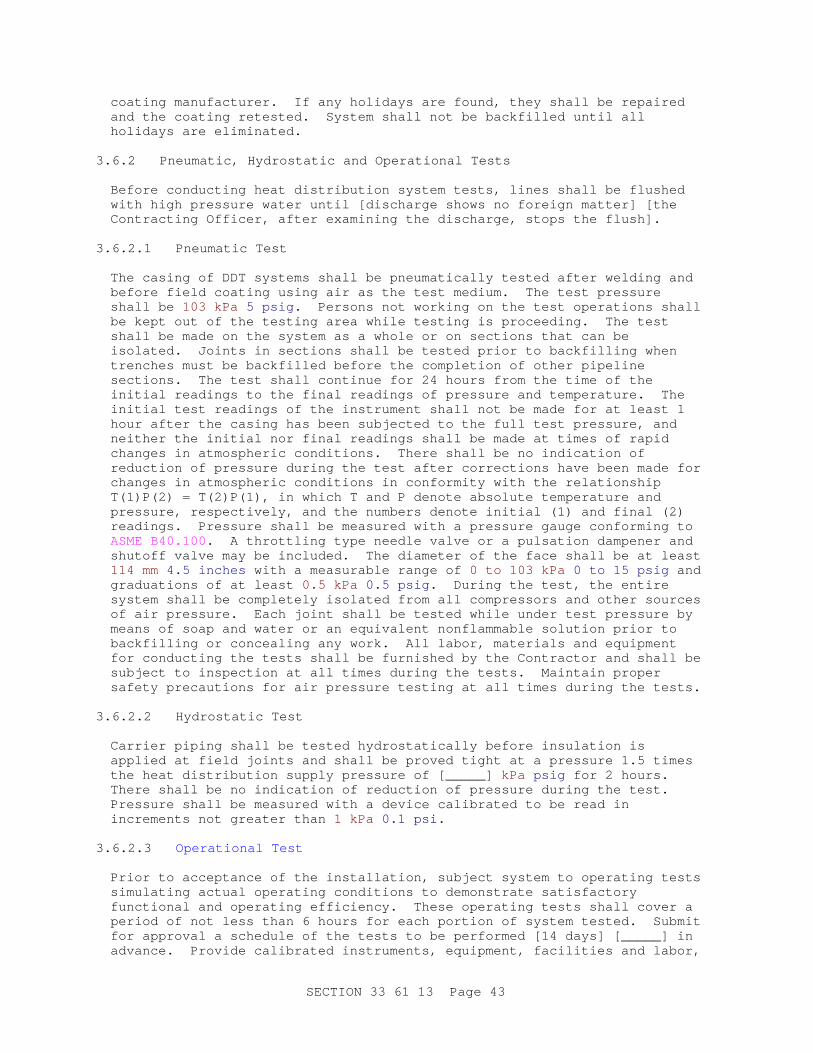
coating manufacturer. If any holidays are found, they shall be repaired and the coating retested. System shall not be backfilled until all holidays are eliminated.
3.6.2 Pneumatic, Hydrostatic and Operational Tests
Before conducting heat distribution system tests, lines shall be flushed with high pressure water until [discharge shows no foreign matter] [the Contracting Officer, after examining the discharge, stops the flush].
3.6.2.1 Pneumatic Test
The casing of DDT systems shall be pneumatically tested after welding and before field coating using air as the test medium. The test pressure shall be 103 kPa 5 psig . Persons not working on the test operations shall be kept out of the testing area while testing is proceeding. The test shall be made on the system as a whole or on sections that can be isolated. Joints in sections shall be tested prior to backfilling when trenches must be backfilled before the completion of other pipeline sections. The test shall continue for 24 hours from the time of the initial readings to the final readings of pressure and temperature. The initial test readings of the instrument shall not be made for at least 1 hour after the casing has been subjected to the full test pressure, and neither the initial nor final readings shall be made at times of rapid changes in atmospheric conditions. There shall be no indication of reduction of pressure during the test after corrections have been made for changes in atmospheric conditions in conformity with the relationship T(1)P(2) = T(2)P(1), in which T and P denote absolute temperature and pressure, respectively, and the numbers denote initial (1) and final (2) readings. Pressure shall be measured with a pressure gauge conforming to ASME B40.100 . A throttling type needle valve or a pulsation dampener and shutoff valve may be included. The diameter of the face shall be at least 114 mm 4.5 inches with a measurable range of 0 to 103 kPa 0 to 15 psig and graduations of at least 0.5 kPa 0.5 psig . During the test, the entire system shall be completely isolated from all compressors and other sources of air pressure. Each joint shall be tested while under test pressure by means of soap and water or an equivalent nonflammable solution prior to backfilling or concealing any work. All labor, materials and equipment for conducting the tests shall be furnished by the Contractor and shall be subject to inspection at all times during the tests. Maintain proper safety precautions for air pressure testing at all times during the tests.
3.6.2.2 Hydrostatic Test
Carrier piping shall be tested hydrostatically before insulation is applied at field joints and shall be proved tight at a pressure 1.5 times the heat distribution supply pressure of [_____] kPa psig for 2 hours. There shall be no indication of reduction of pressure during the test. Pressure shall be measured with a device calibrated to be read in increments not greater than 1 kPa 0.1 psi .
3.6.2.3 Operational Test
Prior to acceptance of the installation, subject system to operating tests simulating actual operating conditions to demonstrate satisfactory functional and operating efficiency. These operating tests shall cover a period of not less than 6 hours for each portion of system tested. Submit for approval a schedule of the tests to be performed [14 days] [_____] in advance. Provide calibrated instruments, equipment, facilities and labor,
SECTION 33 61 13 Page 43
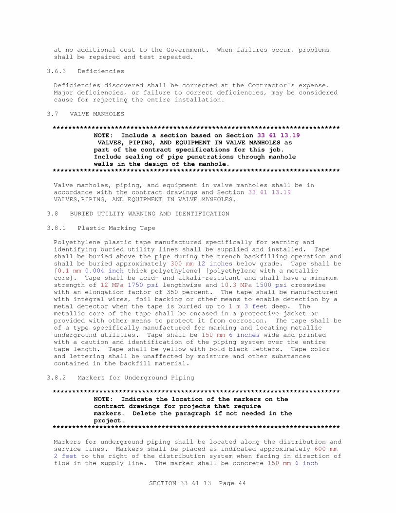
at no additional cost to the Government. When failures occur, problems shall be repaired and test repeated.
3.6.3 Deficiencies
Deficiencies discovered shall be corrected at the Contractor's expense. Major deficiencies, or failure to correct deficiencies, may be considered cause for rejecting the entire installation.
3.7 VALVE MANHOLES
**************************************************************************NOTE: I ncl ude a sect i on based on Sect i on 33 61 13. 19 VALVES, PI PI NG, AND EQUI PMENT I N VALVE MANHOLES as par t of t he cont r act speci f i cat i ons f or t hi s j ob. I ncl ude seal i ng of pi pe penet r at i ons t hr ough manhol e wal l s i n t he desi gn of t he manhol e.
**************************************************************************
Valve manholes, piping, and equipment in valve manholes shall be in accordance with the contract drawings and Section 33 61 13.19 VALVES,PIPING, AND EQUIPMENT IN VALVE MANHOLES.
3.8 BURIED UTILITY WARNING AND IDENTIFICATION
3.8.1 Plastic Marking Tape
Polyethylene plastic tape manufactured specifically for warning and identifying buried utility lines shall be supplied and installed. Tape shall be buried above the pipe during the trench backfilling operation and shall be buried approximately 300 mm 12 inches below grade. Tape shall be [ 0.1 mm 0.004 inch thick polyethylene] [polyethylene with a metallic core]. Tape shall be acid- and alkali-resistant and shall have a minimum strength of 12 MPa 1750 psi lengthwise and 10.3 MPa 1500 psi crosswise with an elongation factor of 350 percent. The tape shall be manufactured with integral wires, foil backing or other means to enable detection by a metal detector when the tape is buried up to 1 m 3 feet deep. The metallic core of the tape shall be encased in a protective jacket or provided with other means to protect it from corrosion. The tape shall be of a type specifically manufactured for marking and locating metallic underground utilities. Tape shall be 150 mm 6 inches wide and printed with a caution and identification of the piping system over the entire tape length. Tape shall be yellow with bold black letters. Tape color and lettering shall be unaffected by moisture and other substances contained in the backfill material.
3.8.2 Markers for Underground Piping
**************************************************************************NOTE: I ndi cat e t he l ocat i on of t he mar ker s on t he cont r act dr awi ngs f or pr oj ect s t hat r equi r e mar ker s. Del et e t he par agr aph i f not needed i n t he project.
**************************************************************************
Markers for underground piping shall be located along the distribution and service lines. Markers shall be placed as indicated approximately 600 mm 2 feet to the right of the distribution system when facing in direction of flow in the supply line. The marker shall be concrete 150 mm 6 inch
SECTION 33 61 13 Page 44
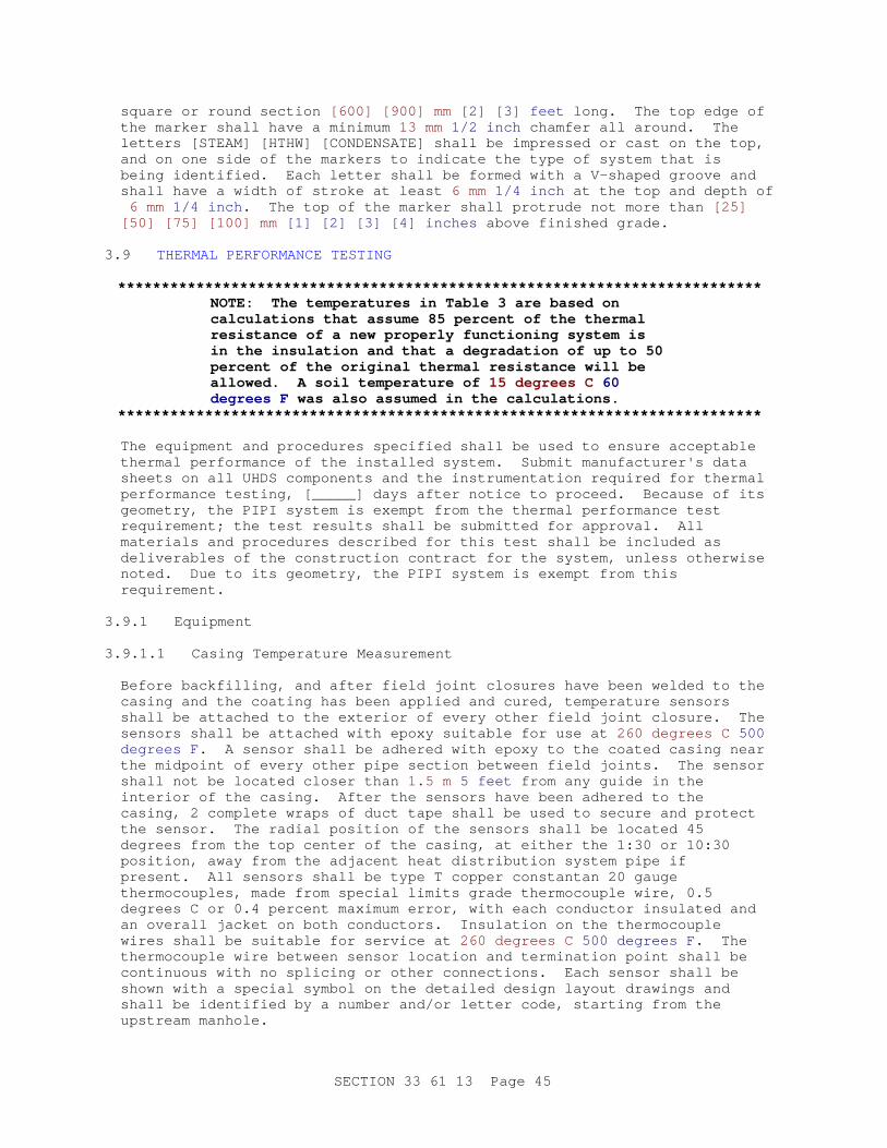
square or round section [600] [900] mm [2] [3] feet long. The top edge of the marker shall have a minimum 13 mm 1/2 inch chamfer all around. The letters [STEAM] [HTHW] [CONDENSATE] shall be impressed or cast on the top, and on one side of the markers to indicate the type of system that is being identified. Each letter shall be formed with a V-shaped groove and shall have a width of stroke at least 6 mm 1/4 inch at the top and depth of 6 mm 1/4 inch . The top of the marker shall protrude not more than [25] [50] [75] [100] mm [1] [2] [3] [4] inches above finished grade.
3.9 THERMAL PERFORMANCE TESTING
**************************************************************************NOTE: The t emper at ur es i n Tabl e 3 ar e based on cal cul at i ons t hat assume 85 per cent of t he t her mal r esi st ance of a new pr oper l y f unct i oni ng syst em i s i n t he i nsul at i on and t hat a degr adat i on of up t o 50 per cent of t he or i gi nal t her mal r esi st ance wi l l be al l owed. A soi l t emper at ur e of 15 degr ees C 60 degr ees F was al so assumed i n t he cal cul at i ons.
**************************************************************************
The equipment and procedures specified shall be used to ensure acceptable thermal performance of the installed system. Submit manufacturer's data sheets on all UHDS components and the instrumentation required for thermal performance testing, [_____] days after notice to proceed. Because of its geometry, the PIPI system is exempt from the thermal performance test requirement; the test results shall be submitted for approval. All materials and procedures described for this test shall be included as deliverables of the construction contract for the system, unless otherwise noted. Due to its geometry, the PIPI system is exempt from this requirement.
3.9.1 Equipment
3.9.1.1 Casing Temperature Measurement
Before backfilling, and after field joint closures have been welded to the casing and the coating has been applied and cured, temperature sensors shall be attached to the exterior of every other field joint closure. The sensors shall be attached with epoxy suitable for use at 260 degrees C 500 degrees F . A sensor shall be adhered with epoxy to the coated casing near the midpoint of every other pipe section between field joints. The sensor shall not be located closer than 1.5 m 5 feet from any guide in the interior of the casing. After the sensors have been adhered to the casing, 2 complete wraps of duct tape shall be used to secure and protect the sensor. The radial position of the sensors shall be located 45 degrees from the top center of the casing, at either the 1:30 or 10:30 position, away from the adjacent heat distribution system pipe if present. All sensors shall be type T copper constantan 20 gauge thermocouples, made from special limits grade thermocouple wire, 0.5 degrees C or 0.4 percent maximum error, with each conductor insulated and an overall jacket on both conductors. Insulation on the thermocouple wires shall be suitable for service at 260 degrees C 500 degrees F . The thermocouple wire between sensor location and termination point shall be continuous with no splicing or other connections. Each sensor shall be shown with a special symbol on the detailed design layout drawings and shall be identified by a number and/or letter code, starting from the upstream manhole.
SECTION 33 61 13 Page 45

3.9.1.2 Carrier Pipe Temperature Measurement
Carrier pipe temperature shall be measured within the manhole where the panel box is located. Carrier pipe temperature shall be measured by a sensor adhered with epoxy directly to the exterior of the carrier pipe. All sensors shall be type T copper constantan 20 gauge thermocouples, made from special limits grade thermocouple wire, 0.5 degrees C or 0.4 percent maximum error, with each conductor insulated and an overall jacket on both conductors. Insulation on the thermocouple wires shall be suitable for service at 260 degrees C 500 degrees F . The thermocouple wire between sensor location and termination point shall be continuous with no splicing or other connections. The location of this sensor shall be at either the 1:30 or 10:30 position. At the location of the sensor, the carrier pipe shall be insulated with calcium silicate insulation at least 125 mm 5 inches thick. This insulation shall extend at least 150 mm 6 inches on each side of the actual sensor location and shall be clad with an aluminum jacket.
3.9.1.3 Terminals
The wires from each casing or carrier pipe temperature sensor shall be extended into the nearest manhole and terminated in a panel box. The panel box shall be a NEMA Type 4 waterproof enclosure, of suitable size, mounted near the top of the manhole at a location near the manhole entrance, accessible without entrance into the manhole, where possible. The termination of the sensor wires shall be with an approved connector of type [OMEGA Miniature Jack Panel (MJP-*-*-T)] [_____]. The thermocouple jack panel shall be mounted to the back plate of the panel box. The temperature sensors shall be labeled at their termination within the panel box; a drawing showing the location of each temperature sensor shall be laminated and attached to the inside of the panel box. All temperature sensors shall be verified as operational by an independent laboratory, hired by the Contractor, after backfilling is complete but before the system is accepted.
3.9.2 Thermal Performance Test
After the system construction is complete, including backfilling, and the system has reached operating condition for at least 30 days, all of the temperature sensors shall be read by an independent laboratory with experience and equipment appropriate for the sensors used. The temperature shall be recorded for each sensor. The temperatures shall be tabulated and submitted in accordance with specified requirements. If temperatures exceed values in Table 3, that portion shall be repaired and temperatures again measured and recorded.
TABLE 3
Carrier Pipe Temperature - TP(degrees C F )
Acceptable Casing Temperature - TC(degrees C F )
121 250 43 110
135 275 47 116
SECTION 33 61 13 Page 46
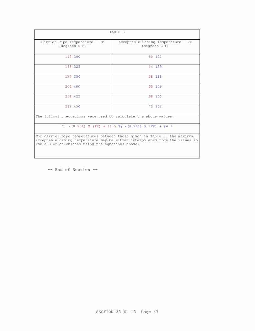
TABLE 3
Carrier Pipe Temperature - TP(degrees C F )
Acceptable Casing Temperature - TC(degrees C F )
149 300 50 123
163 325 54 129
177 350 58 136
204 400 65 149
218 425 68 155
232 450 72 162
The following equations were used to calculate the above values:
T, <(0.261) X (TP) + 11.5 T@ <(0.261) X (TP) + 44.3
For carrier pipe temperatures between those given in Table 3, the maximum acceptable casing temperature may be either interpolated from the values in Table 3 or calculated using the equations above.
-- End of Section --
SECTION 33 61 13 Page 47