ug series product manual - ahi...
TRANSCRIPT

UG16/20/25/30/35/38/40
UG
SE
RIE
S PR
OD
UC
T M
AN
UA
L
AHI GROUP
Sliding RailMan Lift

Product Schematic Diagram 2Product Introduction 3Technical Specifications 3
Operating Instructions 6Manual Lowering of Platform from Ground Controls 7Emergency Lowering 7Machine Achieving Optimal Performance 8Operation of Tilt Support System 9
Laser Position Indicator-Operating Instructions 12Fibreglass Cage 12Hour Meter 12Dual Power Source Machine 13
Electrical System 14Hydraulic System 15Trouble Shooting 16Instructions for Use and Maintenance of Battery 17
Safety Rules 4Safety Decal 5
Loading & Unloading 10UG35 Outrigger Pocket 11UG38DC Back Support 11
12
3
123
12
43
5
1234
1234
12
A
B
C
D
E
F
Congratulations on your purchase of thisquality Up-Lift Product!
Before operating, please read this manual thoroughly and follow the safety rules closely.
Table of ContentsINTRODUCTION
SAFETY
USING THE MACHINE
TRANSPORT
OPTIONS
MAINTENANCE
1
UG Series Product Manual

1 Product Schematic Diagram
Note: Non-standard lift with Fibreglass platform cage has different appearance.
UG Series machine
2
UG Series
UG Series Product Manual
A INTRODUCTION
Lifting lug
Emergency Lower Valve
PlatformControls
Brake wheels Explosion Relief Valve
Platform
Spirit Level
Outriggers
Ground Controls
HydraulicSystem
Tilt-back(if supplied)
LoadingMechanism
MachinePlate

Up-Lift UG series elevating work platforms employ advanced technology, powered by a dynamic hydraulic system and is safe and reliable.
The components which make up the UG product are from the best quality sources, with most of key components imported from western countries. The product is equipped with a number of advanced features, and has a patented back-up power feature allowing lowering of the platform during power black-outs. As a consequence, operators of Up-Lift feel a greater sense of safety comparing with many similar products.
Up-Lift UG elevating work platforms are extensively used for cleanings, decorating, maintenance and aerial signage work in hotels, restaurants, department stores, emporiums, shopping centers, airport departure lounges, sports stadiums, convention centers and stadiums, as well as factories, hospitals, universities and colleges. It can easily pass through standard doorways and elevator lifts and is especially suited to small confined working space applications.
The company reserves the right to alter its design & specification without prior notification.
3
UG Series Product Manual
ModelItem
Max Platform Height (m) 4.7 6.1 7.5 8.8 10.3 11.7 12.3
Max Working Height (m) 6.7 8.1 9.5 10.8 12.3 13.7 14.3
Total Weight (kg) 315/357 340/382 360/402 380/422 415/457 455/497 515/557
Stored Dimensions (m) 1.22x0.8x1.78 1.22x0.8x1.98 1.28x0.8x1.98 1.34x0.8x1.98 1.40x0.8x1.98 1.47x0.8x1.98 1.42x0.8x2.80
Platform Dimensions (m) 0.68x0.66x1.1 0.68x0.66x1.1 0.68x0.66x1.1 0.68x0.66x1.1 0.68x0.66x1.1 0.68x0.66x1.1 0.68x0.66x1.1
Outriggers Foot-Print (m) 1.55x1.75 1.55x1.75 1.55x1.75 1.55x1.75 2.06x2.26 2.34x2.70 2.33x2.58
Wall Access-Distance (m) 0.12 0.12 0.12 0.12 0.36 0.53 0.53
Rated Load (kg) 200/1 People 159/1 People 159/1 People 159/1 People 136/1 People 136/1 People 136/1 People
Lateral Force (N) 200N 200N 200N 200N 200N 200N 200N
Power Rating (kW) 1.1/1.6 1.1/1.6 1.1/1.6 1.1/1.6 1.1/1.6 1.1/1.6 1.1/1.6
Voltage (v) AC/DC 230 /12 230/12 230/12 230/12 230/12 230/12 230/12
Tilted Dimensions (m) -- -- -- -- -- -- 2.85x0.8x1.98
UG16 UG20 UG25 UG30 UG35 UG38 UG40
A INTRODUCTION
2 Product Introduction
3 Technical Specifications

4
UG Series Product Manual
B SAFETY1 Safety RulesAll personnel should read carefully this warning sign and the instruction manual and follow the operating rules. Failure to do so could result in serious safety hazard.
ENSURE that no person or object is placed beneath the platform before and during operation of the machine.
NEVER move the machine into overhead beams or objects.
NEVER operate the machine while under the influence of alcohol.
NEVER operate the machine under poor lighting conditions.
NEVER try to move the machine while platform is loaded or with the outriggers installed.
NEVER elevate the platform in windy environments.
This machine is designed for non-wind condition.
NEVER exceed the load limit specified for the machine. NEVER use machine as a goods lift or a people mover.
NEVER operate the machine within proximity of power lines, or use as an earth for welding.
Electrical shock can kill you. This machine won't protect you from shock.
NEVER sit on, stand on or climb over the platform top-rail or mid-rail to conduct aerial work.NEVER use ladders, planks or other devices to increase the height of the platform.
NEVER operate the platform if the level indicator shows the machine is not on a level position. This machine is designed to be elevated when the chassis is level. ENSURE that the outriggers are on firm solid ground.

5
UG Series Product Manual
B SAFETY2 Safety Decal
Item Design Qty Position Title Item Design Qty Position Title
1 1 Crush & strain hazard 20 1 Check chains
2 1 Hazard head crush 21 1 Brake wheels
3 6 Lock stabilisers small 22 1 Do not step
4 1 Tilt bubble OK nok 23 1 One person only
5 4 Stabiliser max load 24 1 Harness anchor point
6 1 Read manual 25 1 Brief instructions
7 1 Rated load 159 kg 26 1 Laser beam
8 2 Up-Lift 27 1 Lock stabilisers
9 1 Model 28 1 Push down slope hazard
10 1 Capacity rating 29 1 Push elevated platformhazard
11 1 Lateral force 200N 30 1 Use tilt-back deviceproperly
12 1 Finger crush hazard 31 1 Hook point
13 1 Hazards & elec distance 32 1 Use Instruction manual &avoid crush & strain
14 1 Emergency lower 33 1 Heavy battery
15 1 Operator incapicated 34 1 Voltage
16 1 Power supply 35 1 Battery cable connection
17 1 Red ascent buttonmaintenance
36 1 Battery notice
18 1 Lower Elec. box 37 1 Battery warning
19 1 Lower Elec. box 38 1 Battery charging
DCBatteryCase
Chassis
Mast -Front
Mast -Rear
Platform
GroundControl
Box

6
UG Series Product Manual
Ground Control Panel Platform Control Panel
1.2.
3. 4.
5.
6. 7. 8. 9.
Move the machine to the location where aerial working is required.Connect power supply to the unit. Turn the key-switch to the "PLATFORM" position. Power supply indicator light will lit up. Install the four out-riggers and position these supporting legs close on firm ground surface. Check that the bubble in the spirit level indicator is centred within the black circle and all four outrigger indicator lights on the base control box are lit up before operating the unit. Adjust the outriggers until the bubble in the spirit level indicator is centred within the black circle, the machine is now leveled for use. Enter the platform by lifting the mid-rail on the access side and close. Once inside the platform, depress the "UP" and "POWER" buttons simultaneously to raise the platform. When the required height is reached, releasing pressure on both buttons will stop the platform. Commence aerial work.After completion of work, check the space below the platform is clear before depressing both the "DOWN" and "POWER" buttons simultaneously to lower the platform to the minimum height position. Releasing the pressure on these buttons STOPS the platform.Never move the machine unless the platform has returned to the lowest position.After operator has completed work, return the outriggers to its stored position. Return the key switch to the OFF position and remove the key for safe keeping. If power supply is cut while the machine is in the elevated position, the electrical system will automatically switch over to the back up power supply allowing normal operation of the unit to reach the ground level position.
Up
Down
Power
C USING THE MACHINE
1 Operating Instructions

7
UG Series Product Manual
C USING THE MACHINE
2 Manual Lowering of Platform from Ground Controls
3 Emergency Lowering
1.
2.
3.
The emergency down valve is located on the side of the ground control box.
To lower the platform, the red dial is turned anti-clockwise.
The lowering speed is dependent on the number of turns of the dial.
Caution must be taken to control the speed of descent.
Return the dial to the closed position prior to re-using the machine.NOTE:
Make sure that no one is beneath the platform.
1. Check that the key switch is in the "OFF" position.2. Twist the Emergency Stop button clockwise to release to on position.3. While holding the key switch to "GROUND" position, press the Down 00button to lower the platform.

8
UG Series Product Manual
This unit is suitable for indoor operation and the operator should as far as possible operate the machine indoors.If the machine is used outdoors, care should be taken to ensure that the ground is firm and solid to prevent instability. Avoid operation under any windy condition.Always check that the outrigger position indicator lights are working properly.Always make sure that the wheel brakes are on when not moving into position.Descent at full height: When the platform is loaded and raised to its highest point, momentarily press the down control buttons. Then fully engage the down control buttons to continue the descent. This minimises the impact to the equipment of a change in hydraulic flow direction.Before using the machine for aerial work, raise the platform slightly without load to ensure normal functioning of the machine.Frequent check should be made of the electricity leakage protection to ensure effectiveness.For maintenance requirement of the hydraulic system, please refer to Section F.If the machine is used frequently, routine maintenance and safety checks should be carried out every 3 months.Regular check of the chain-drive system for wear and tear at least on a quarterly basis. Apply N32 oil on chain friction points as well as wheels points as required.Keep machine away from dust and rain. Never store the machine outdoors or in an area of high humidity or heat. During storage, keep the machine covered with a protective cover.Only qualified professionals are allowed to undertake dismantle any part of the machine or conduct maintenance on the machine. If unsure, please contact supplier.
1.
2.
3.
4.
5.
6.
7.
8.
9.
10.
11.
12.
C USING THE MACHINE
4 Machine Achieving Optimal Performance

9
UG Series Product Manual
1
2
3
4
5
6
C USING THE MACHINE5 Operation of Tilt Support System
Up-Lift UG Series Personnel Elevating Work Platforms is equipped with an inclined-back support system to allow it to pass through standard doorways. On the UG40 model, the inclined-back support system is supplied as standard equipment.
Please read and adhere strictly to the following operating rules:
Preparing for Storage or Moving of Machine through Standard Door
1. While on a level & flat ground, remove the pin retainer to release xxlocking pin while holding the tilt back frame. (Refer to figure 1) xxEnsure that the frame is partially supported while being lowered. At xxleast two people are required to operate the tilt-back frame.
2. While holding the tilt back support, lower the gas cylinder on the tilt xxback frame to align the holes on its end with the holes on the xxbracket. These steps should only be implemented when there is no xxperson or object behind or under the tilt back frame. Insert the xxlocking pin and hold it in position by the pin retainer. (Refer to xxfigure 2&3)
3. Pull out the leverage arm on the front end of the chassis until the xxspring-loaded pin locks it in position. (Refer to figure 4)
4. Tilt the machine slowly onto the inclined supporting frame by lifting xxthe front leverage arm handle. Under no circumstances should the xxmachine be dropped onto the tilt back support. This procedure must xxbe handled slowly until the machine rests firmly on the castor xxwheels. (Refer to figure 5 )
5. Return the leverage arm to its stored position. The machine is now xxready for moving through standard doorways. (Refer Figure 6)
Preparing to Raise the Machine for Normal Operation
1. While on a level or flat ground, pull out slowly the leverage arm xxfrom its stored position until it is locked in position.
2. Gently push up the rear mast body while a second person on the xxfront of the machine pull down on the leverage arm until the xxmachine returns to its vertical position.
3. Push the inclined-back frame upwards until the gas spring cylinder is xxvertical and the holes on the frame coincides with the bracket holes xxon the back of the machine. Insert the locking pin and pin retainer.
4. Return the leverage arm to its stored position.
5. The machine is now ready for normal operation. (Refer Section C – xxUSING THE MACHINE)

10
UG Series Product Manual
To position the machine into a vertical standing position to allow the locking hook to be disengaged from the lower mast.
Step 1
A. Loading
B. Unloading
Pull out the level arm after releasing the locking pin. Ensure that the retainer pin is engaged in the allocated hole. Dismantle any timber block placed against the castor wheels of the machine for protection during transport. Cut the steel bands which tie the machine onto the timber base, use a fork lift to lift the machine from its timber base with a sling as shown. Adjust the sling so it is close to the centre of gravity of the machine. Gently lower the machine onto the floor with care.With two people one holding the leverage arm handle downwards and the other guiding the forklift driver, gently lift the machine into its vertical standing position using the sling as shown.With one person (approx.75kg) standing in the cage at its minimum position, ensure that the locking hook is disengaged from the lower mast assembly.
Fig.1:
Fig.2:
Fig.3:
Fig.4:
Extreme care should be taken on the Mast Cover, Cage, the Upper & Lower Control Box when unpacking to avoid any damages. Unloading procedure must be strictly followed. Incorrect handling may cause serious damage and personal injury.
WARNING:
D TRANSPORT1 Loading & Unloading
Fig.4Fig.3
Hoisting
Fig.1
Ensure retainerpin is lockedin position
Timber Block
Steel band whichties the machine onto the timber base
Timber base
Machine Documentationsto be placed here
Fig.2
Hoisting
For distance transportation, the machine can be loaded onto a truck using the loading method as shown in the diagram.

11
UG Series Product Manual
The new UG35 outrigger pocket has been designed for the stored outriggers to avoid touching the top rail of the platform cage. To store the outriggers in the pockets and maintain the overall machine stored height of 2 metres, it is necessary to wind the screwjacks down to more than the normal amount before storing in the pockets (Refer adjacent photo).
To prepare the machine for transport using the loading device provided,
follow carefully the instructions below:
A. First use the hook provided (refer 3 in the photo) to lock the sliding
00bar in position. Then remove the two retaining pins as shown in (2)
00and gradually lower the loading assembly (see 1 in the photo).
B. Remove the battery box and place carefully on the floor (See 4 in the
00photo). As the battery box is quite heavy (approx. 40 kg), recommend
00two people handle this.
C. Return the loading assembly (refer to 1 in the photo) back into position and lock using the 00two retainer pins provided. The loading device is now ready for use to transport the machine.
D. Once transportation is complete, return the battery box to its position by following the above 00steps in reverse.
D TRANSPORT
2 UG35 Outrigger Pocket
3 UG38DC Back Support
1
3
4
2
Before putting the machine through a trial run, make sure that the following items are carried out:
The locking hook under the mast is disengaged and the machine is standing upright. (Follow Fig.4)Check for any abnormal signs such as loose bolts on the machine or any damage during transport. Rectify as required.The machine is now ready for trial run. (Refer to Section C - USING THE MACHINE)
1.
2.
3.

12
UG Series Product Manual
E OPTIONS
1 Laser Position Indicator
2
3
Push the machine to the location beneath where aerial working is required.Press the button on the side of the laser position indicator inside the platform.Check the spot where the laser beam is directed to see if this is within the desired working area.If the laser beam is outside the desired working area, adjust the machine position so that the laser beam shines within the working area.
WARNING:NEVER LOOK INTO THE LASER BEAM, Remove cap on the outlet to check work position. Replace cap immediately after use to avoid harm to eyes.
Laser Beam From here
Push Button
Fibreglass Cage
An optional fibreglass cage can be supplied with any of AHI's non-insulated work platforms. The modified cage affords low-voltage protection to an operator experiencing single-point contact with a live, low-voltage electrical circuit. The cage is compliance tested in accordance with Clause 1.12.5.6 of Australian Standard 1418.10 v 2004.With the fibreglass cage, the platform dimensions are likely to change. Please confirm these dimensions with the machine supplier.
Hour Meter
An optional hour meter can be used to record the number of hours the machine has been used. This usage record helps in determining the need for maintenance service.

13
UG Series Product Manual
14
*Dual Power Source means Direct AC source or AC source from DC battery & inverter pack.
CHARGING PROCEDURE:
When charging is required, connect power plug 1 directly to the 230V power source Next connect power plug 2 to power outlet 1 to commence battery charging (For battery maintenance, refer to Section F.4). After charging, disconnect power plug 2 and store power plug 1 inside trolley properly.NOTE: During charging, the green indicator light is blinking. If this is not the case, the charger is in protective mode (charging is not possible). It is necessary to disconnect power plug 1 and 2 and re-connect, until the green indicator on the charger starts blinking.
AC OPERATIONWhen using the 230AC power source, connect the power plug from the hydraulic motor on the lift directly to the 230V AC power source or wall power point. Follow the steps to commence operation.DC OPERATIONWhile using the portable power source (on the trolley provided), connect the AC power plug from the hydraulic motor on the lift to the output 2, from the inverter. Check that the switch on the inverter is on. Follow the steps to commence normal operation. After completing aerial work, switch off the inverter and disconnect power plug from the hydraulic motor. Store the portable power trolley in a cool and dry area.
NORMAL OPERATING PROCEDURE:
Power Output Socket
Inverter Switch
Charge Meter
Handles
Charging Port
Power CordStorage Box
Indicator Light 1
*
Indicator Light 2
Fan 2Fan 1
Reset Switch
AC Input: 220 - 240V
LED1: Red - Power OnLED2: Red - ChargingLED2: Green - Charged
LED1
LED2
Type A (Standard) Type B (Optional)
E OPTIONS
4 Dual Power Source Machine*

14
UG Series Product Manual
LoweringSolenoid
Valve
Power managementOvervoltage protectionOvercurrent protectionUndervoltage protection
Up
Down
Up
Down
EmergencyStop
EmergencyStop
EmergencyStop
EmergencyStop
MotorPlatform Control
Base Electrical Control Box
OutriggerCheck
CityPower Commutation Filter
PowerTransister
Switch
Commutation & Filter
Pulse durationModulation
ComparatorAmplifier
PedestalVoltage
SamplingCircuit
24V Battery
Operation
Relay
(A
C m
odel
s bac
k-up
bat
tery
)
14
F MAINTENANCE
1 Electrical System Repairs by any unauthorised personnel may result in serious personal injury or death. Any interference with and electrical the hydraulic system may also invalidate the product warranty.
Note:
15
UG Series Product Manual
14
F MAINTENANCE
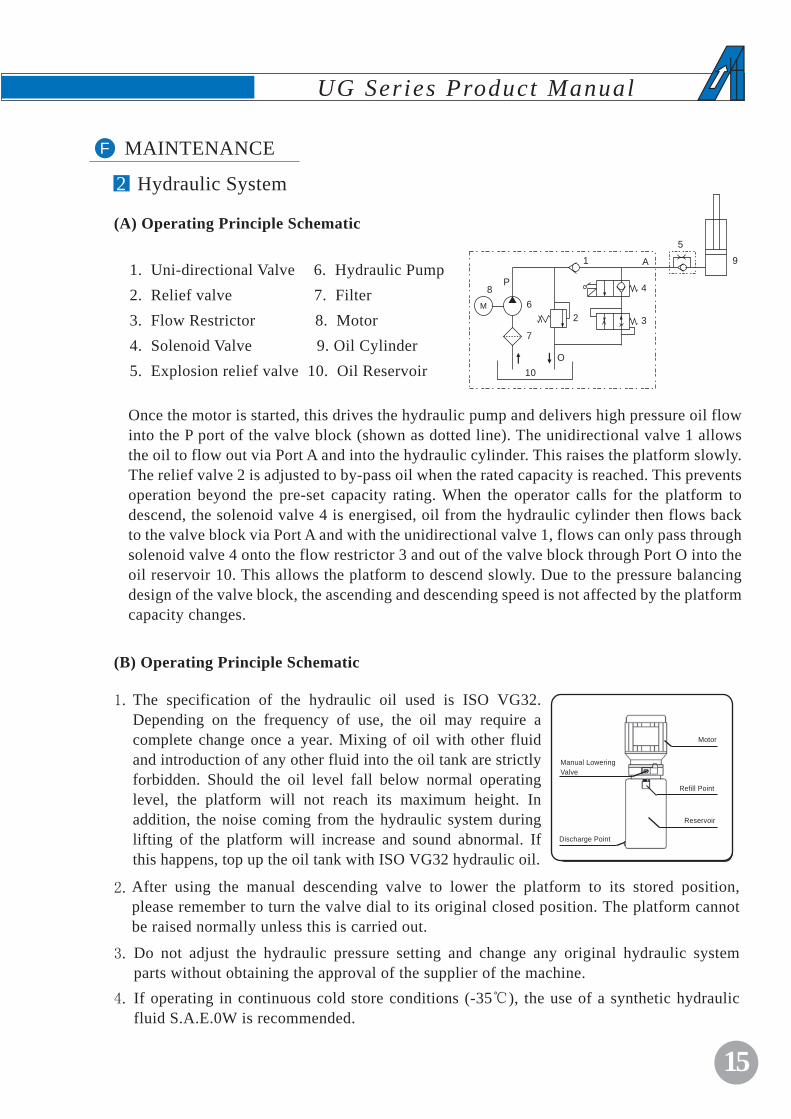
2 Hydraulic System
The specification of the hydraulic oil used is ISO VG32. Depending on the frequency of use, the oil may require a complete change once a year. Mixing of oil with other fluid and introduction of any other fluid into the oil tank are strictly forbidden. Should the oil level fall below normal operating level, the platform will not reach its maximum height. In addition, the noise coming from the hydraulic system during lifting of the platform will increase and sound abnormal. If this happens, top up the oil tank with ISO VG32 hydraulic oil.
Motor
Refill Point
Reservoir
Manual LoweringValve
Discharge Point
Do not adjust the hydraulic pressure setting and change any original hydraulic system parts without obtaining the approval of the supplier of the machine.If operating in continuous cold store conditions (-35℃), the use of a synthetic hydraulic fluid S.A.E.0W is recommended.
1.
2.
3.
4.
After using the manual descending valve to lower the platform to its stored position, please remember to turn the valve dial to its original closed position. The platform cannot be raised normally unless this is carried out.
(B) Operating Principle Schematic
(A) Operating Principle Schematic
Once the motor is started, this drives the hydraulic pump and delivers high pressure oil flow into the P port of the valve block (shown as dotted line). The unidirectional valve 1 allows the oil to flow out via Port A and into the hydraulic cylinder. This raises the platform slowly. The relief valve 2 is adjusted to by-pass oil when the rated capacity is reached. This prevents operation beyond the pre-set capacity rating. When the operator calls for the platform to descend, the solenoid valve 4 is energised, oil from the hydraulic cylinder then flows back to the valve block via Port A and with the unidirectional valve 1, flows can only pass through solenoid valve 4 onto the flow restrictor 3 and out of the valve block through Port O into the oil reservoir 10. This allows the platform to descend slowly. Due to the pressure balancing design of the valve block, the ascending and descending speed is not affected by the platform capacity changes.
1. Uni-directional Valve 6. Hydraulic Pump2. Relief valve 7. Filter3. Flow Restrictor 8. Motor4. Solenoid Valve 9. Oil Cylinder 5. Explosion relief valve 10. Oil Reservoir
5
A
4
3
68
P
M
7
10O
1
2
9

16
UG Series Product Manual
Please ensure machine is on a firm and level ground. All four outriggers must be correctly inserted prior to commencing any repair works.
Please read the product manual and maintenance manual carefully before carrying out any repair work.
If problem persists after following the steps below, please cease using the equipment and contact the manufacturer or authorised representative immediately.
1.
2.
3.
Trouble Probable Cause Remedy
Add hydraulic oilInsufficient hydraulic oilPlatform could not reach max height
Stop using the equipment, contact supplier for replacement.Oil leaking
Platform could not be raised although motor is running
Excessive platform capacityEmergency down valve is left open Insufficient hydraulic oilHydraulic oil is contaminated
1.2.3.4.
Keep to capacity specifiedClose the emergency down valveAdd hydraulic oilReplace hydraulic oil
1.2.3.4.
Platform descends gradually from raised position
Close emergency down valve fullyReplace hydraulic oil, clean filterContact supplier to arrange replacement.
1.2.3.
Emergency down valve is left partially openOil contaminated causing relief valve to remain open Hydraulic seal needs replacement
1.
2.
3.
Hydraulic seal needs replacementOil leakage from fittings.
1.2.
NB. To retrieve the platform open the emergency down valve.
Platform could not descend
Power not connected and back-up battery is flat.Oil cylinder bypass causing explosion relief valve to block oil flow. Pressure release valve damage, cannot open to release pressure.
1.
2.
3.
Check power connection and fix problem. Replace back-up battery if required.Press Up & Power button to raise platform and slowly open the emergency down valve, repeat this cycle if required.Contact supplier for replacement.
1.
2.
3.
Platform could not be raised; electric motor is not running
Key switch is in OFF positionPower connection faulty (DC model: battery level low)Outriggers not insert properlyEmergency stop button is depressed.Electric motor faulty
1.2.
3.4.5.
Turn key switch to PLATFORM positioncheck power point(DC model: recharge battery)Adjust outrigger position till outrigger indicator lights are all on.Release emergency stop button Contact supplier for replacement
1.2.
3.
4.5.
14F MAINTENANCE
3 Trouble Shooting

17
UG Series Product Manual
14F MAINTENANCE
4 Instructions for Use and Maintenance of Battery ( DC Models)
When transporting the DC powered personnel lift, the battery casing and the battery should be detached from the rear of the machine to prevent leakage or damage to the battery casing.
To prepare the machine for use, install the outriggers, then load the battery box (including battery inside) onto the two retaining pins fitted on both side of the central mast and ensure this is fitted securely onto the back of the central mast.
For charging of battery, please follow the instructions on charging operation. When the charger indicator changes from red to green, the battery is fully charged. Continue charging for about an hour will ensure maximum performance of the battery.
If the charged battery has been used or left unused for a period of time, recharging is required.
Store the battery in a cool and dry area to reduce loss of power during storage period.
For lead-acid batteries, check battery fluid level before charging. If the electrolyte level is less than 10 mm above the plates, add distilled water or battery charging fluid. Do not over-fill fluid which may result in dilution thus shorten the life of the battery. Take care not to add too much fluid causing over flowing. After topping up fluid with distilled water, the battery should be recharged for at least half an hour to enable the distilled water to mix thoroughly with the battery fluid and avoid freezing during winter. (This above step is NOT required for Maintenance-free batteries).
Check the battery and the terminals regularly to ensure they are secured tightly in position. Inspect the insulation casing for worn spots, cracks or broken terminals and repair them immediately.
Inspect the battery and the terminals for signs of corrosion at the terminals resulting from overflowing of fluids (for lead-acid batteries only). Clean the battery thoroughly with hot water and dry with a piece of clean cloth thereafter. Remove and clean the terminals and the connecting cables as well. Before refitting the cables, apply a thin layer of industrial vaseline.
To connect the battery and the charger, set the power switch to the "OFF” position. Ensure that the positive terminal on the battery is connected to the positive socket of the charger and vice versa.
Charging must be carried out in a well-ventilated area, away from inflammable materials as charging may result in sparks or flames, which may result in explosion.
Ensure the connecting socket on the battery casing is properly maintained to avoid power disruption.
Battery fluid in lead-acid batteries is highly corrosive. Rinse thoroughly with clean water if spilled fluid comes into contact with hands or eyes.

18
UG Series Product Manual
Keep batteries fully charged when in storage. Prolonged storage at low charge will result in reduced battery performance. Disconnect the battery from the load / equipment before longer term storage. Store in a cool dry place.
The battery casing carrying the charger contains an ammeter, which indicates the charge rate. All power usage should stop when the power discharge level indicated by the ammeter reaches 70%. This is strongly recommended to ensure maximum battery life.
If the charge level remains low after a long period of charging, check if the specific gravity level of each of the cells is between 1.277 +0.007. If any reading falls below 1.230, the battery is damaged and should be replaced. For Maintenance free batteries, check the health of the battery and consider replacing if charge level remains low after charging.
WARNING• Do not charge batteries under direct sunshine or near heat generator.• Battery should be charged immediately after use. If battery is stored without ---recharging, performance could deteriorate.• Avoid operating the battery below -15OC (5OF) or above 50OC (122OF).• Batteries are heavy and should be handled appropriately.• Never disassemble the battery. Clean battery with moist soft cloth.• Never dispose battery into fire. Recycle any used battery.• Do not short the battery terminals.
ISO9001 Quality Management System Certification.
CE Certification
Australian standards AS 1418.10
The product is insured by CPPIC
The Company reserves the right to alter its design & specification without prior notification.
Version: Dec 2014