ug266: silicon labs gecko bootloader user’s guide released with the silicon labs bluetooth sdk...
TRANSCRIPT

silabs.com | Building a more connected world. Rev. 0.2
KEY FEATURES
Describes the Gecko Bootloader compo-nents.
Summarizes how the Gecko Bootloader performs application updates and boot-loader updates.
Reviews how to create customized boot-loaders in Simplicity Studio.
Discusses the key configuration changes for various bootloader types.
Describes Gecko Bootloader security features and discusses how to use them.
Discusses using the Gecko Bootloader with different protocols.
UG266: Silicon Labs Gecko Bootloader User’s Guide
This document describes the high-level implementation of the Silicon Labs Gecko Bootloader for EFR32 SoCs (System on Chips) and NCPs (Network Co-Processors), and provides information on how to get started using the Gecko Bootloader with Silicon Labs wireless protocol stacks. If you are not familiar with the basic principles of performing a firmware update or want more information about update image files, refer to UG103.6: Application Development Fundamentals: Bootloading.

UG266: Gecko Bootloader User Guide
Overview
silabs.com | Building a more connected world. Rev. 0.2 | 1
1 Overview
The Silicon Labs Gecko Bootloader is a common bootloader for all the newer MCUs and wireless MCUs from Silicon Labs. The Gecko Bootloader can be configured to perform a variety of bootload functions, from device initialization to firmware updates. Key features of the bootloader are:
Useable across Silicon Labs Gecko microcontroller and wireless microcontroller families
In-field updateable
Configurable
Enhanced security features, including:
Secure Boot: When Secure Boot is enabled, the bootloader enforces cryptographic signature verification of the application im-age on every boot, using asymmetric cryptography. This ensures that the application was created and signed by a trusted party.
Signed update image file: The Gecko Bootloader supports enforcing cryptographic signature verification of the update image file. This allows the bootloader and application to verify that the application or bootloader update comes from a trusted source before starting the update process, ensuring that the image file was created and signed by a trusted party.
Encrypted update image file: The image file can also be encrypted to prevent eavesdroppers from acquiring the plaintext firm-ware image.
The Gecko Bootloader uses a proprietary format for its update images, called GBL (Gecko Bootloader). These images are produced with the file extension “.gbl”. Additional information on the GBL file format is provided in UG103.6: Application Development Fundamen-tals: Bootloading.
The Gecko Bootloader has a two-stage design, where a minimal first stage bootloader is used to update the main bootloader. The first stage bootloader only contains functionality to read from and write to fixed addresses in internal flash. To perform a main bootloader update, the running main bootloader verifies the integrity and authenticity of the bootloader update image file. The running main boot-loader then writes the update image to a fixed location in flash and issues a reboot into the first stage bootloader. The first stage boot-loader verifies the integrity of the main bootloader firmware update image, by computing a CRC32 checksum before copying the update image to the main bootloader location.
The main bootloader consists of a common core, drivers, and a set of plugins that give the bootloader specific capabilities. The com-mon bootloader core is delivered as a precompiled library, while the plugins are delivered as source code. The common bootloader core contains functionality to parse GBL files and flash their contents to the device.
The Gecko Bootloader can be configured to perform firmware updates in standalone mode (also called a standalone bootloader) or in application mode (also called an application bootloader), depending on the plugin configuration. Plugins can be enabled and configured through the Simplicity Studio IDE.
A standalone bootloader uses a communications channel to get a firmware update image. NCP (network co-processor) devices always use standalone bootloaders. Standalone bootloaders perform firmware image upgrades in a single-stage process that allows the appli-cation image to be placed into flash memory, overwriting the existing application image, without the participation of the application itself. In general, the only time that the application interacts with a standalone bootloader is when it requests to reboot into the bootloader. Once the bootloader is running, it receives packets containing the firmware update image by a physical connection such as UART or SPI. To function as a standalone bootloader, a plugin providing a communication interface such as UART or SPI must be configured.
An application bootloader relies on the application to acquire the firmware update image. The application bootloader performs a firm-ware image upgrade by reprogramming the device’s flash with the firmware update image stored in a region of flash memory referred to as the download space. The application transfers the firmware update image to the download space in any way that is convenient (UART, over-the-air, and so on). The download space is either an external memory device such as an EEPROM or dataflash or a sec-tion of the chip’s internal flash. The Gecko Bootloader can partition the download space into multiple storage slots, and store multiple firmware update images simultaneously. To function as an application bootloader, a plugin providing a bootloader storage implementa-tion has to be configured.
Silicon Labs provides example bootloaders that come with a preconfigured set of plugins for configuration in either standalone or appli-cation mode, as described in section Configuring the Gecko Bootloader. The Silicon Labs wireless protocol SDKs also include pre-compiled bootloader images for EFR32xG12 parts. As of this writing the images shown in the following table are provided.
Note: The bootloader security features are not enabled in these images.

UG266: Gecko Bootloader User Guide
Overview
silabs.com | Building a more connected world. Rev. 0.2 | 2
Table 1. Prebuilt Bootloader Images
Use Stack Image Name Mode Interface
SoC EmberZNet PRO / Silicon Labs Thread
SPI Flash Storage Bootloader Application SPI Serial Flash
SoC Bluetooth Bluetooth In-Place OTA DFU Bootloader
Application OTA/internal flash
NCP EmberZNet PRO / Silicon Labs Thread UART XMODEM Bootloader Standalone UART (EZSP)
NCP Bluetooth BGAPI UART DFU Bootloader Standalone UART (BGAPI)
The following sections provide an overview of the Gecko Bootloader common core, drivers, and plugins. For details see the Gecko Bootloader API Reference, shipped with the SDK in the platform/bootloader/documentation folder.
1.1 Core
The bootloader core contains the bootloader’s main functions. It also contains functionality to write to the internal flash, an image parser to parse and act upon the contents of GBL update files, and functionality to boot the application in main flash. The first word of SRAM is used as shared memory between the bootloader and the application to flag the reason for a reset. The different possible reset reasons are defined in the Reset Information part of the Application Interface, in the file btl_reset_info.h.
The image parser can also optionally support the legacy Ember Bootloader (EBL) file format, but none of the security features offered by the Gecko Bootloader are supported if support for legacy EBL files is enabled.
1.2 Drivers
Different bootloading applications require different hardware drivers for use by the other components of the bootloader.
Driver modules include:
Delay: Simple delay routines for use with plugins that require small delays or timeouts.
SPI: Simple, blocking SPI master implementation for communication with external devices such as SPI flashes.
SPI Slave: Flexible SPI Slave driver implementation for use in communication plugins implementing SPI protocols. This driver sup-ports both blocking and non-blocking operation, with DMA (Direct Memory Access) backing the background transfers to support non-blocking operation.
UART: Flexible serial UART driver implementation for use in communication plugins implementing UART protocols. This driver sup-ports both blocking and non-blocking operation, with DMA backing the background transfers to support non-blocking operation. Ad-ditionally, support for hardware flow control (RTS/CTS) is included.
1.3 Plugins
All parts of the bootloader that are either optional or that may be exchanged for different configurations are implemented as plugins. Each plugin has a generic header file, and one or more implementations. Plugins include:
Communication
UART: XMODEM UART: BGAPI SPI: EZSP
Debug
GPIO Activation
Security
Storage
Internal flash External SPI flash

UG266: Gecko Bootloader User Guide
Overview
silabs.com | Building a more connected world. Rev. 0.2 | 3
1.3.1 Communication
The Communication plugins provide an interface for implementing communication with a host device, such as a computer or a micro-controller. Several plugins implement the communication interface, using different transports and protocols.
BGAPI UART DFU: By enabling the BGAPI communication plugin, the bootloader communication interface implements the UART DFU protocol using BGAPI commands. This plugin makes the bootloader compatible with the legacy UART bootloader that was previously released with the Silicon Labs Bluetooth SDK versions 2.0.0-2.1.1 See AN1053: Bluetooth® Device Firmware Update over UART for EFR32xG1 and BGM11x Series Products for more information about this legacy bootloader.
EZSP-SPI: By enabling the EZSP-SPI communication plugin, the bootloader communication interface implements the EZSP proto-col over SPI. This plugin makes the bootloader compatible with the legacy ezsp-spi-bootloader that was previously released with the EmberZNet and Silicon Labs Thread wireless stacks. See AN760: Using the Ember Standalone Bootloader for more information about legacy Ember standalone bootloaders.
UART XMODEM: By enabling the UART XMODEM communication plugin, the bootloader communication interface implements the XMODEM-CRC protocol over UART. This plugin makes the bootloader compatible with the legacy serial-uart-bootloader that was previously released with the EmberZNet and Silicon Labs Thread wireless stacks. See AN760: Using the Ember Standalone Boot-loader for more information about legacy Ember standalone bootloaders.
1.3.2 Debug
This plugin provides the bootloader with support for debugging output. If the plugin is configured to enable debug prints, short debug messages will be printed over Serial Wire Output (SWO), which can be accessed in multiple ways, including using Simplicity Com-mander, and by connecting to port 4900 of the Wireless Starter Kit TCP/IP interface.
1.3.3 GPIO Activation
This plugin provides functionality to enter firmware update mode automatically after reset if a GPIO pin is active during boot. The GPIO pin location and polarity are configurable.
1.3.4 Security
Security plugins provide implementations of cryptographic operations as well as functionality to compute checksums and to read cryp-tographic keys from manufacturing tokens.
Modules include:
AES: AES decryption functionality
CRC16: CRC16 functionality
CRC32: CRC32 functionality
ECDSA: ECDSA signature verification functionality
SHA-256: SHA-256 digest functionality
1.3.5 Storage
These plugins provide the bootloader with multiple storage options for SoCs. All storage implementations have to provide an API to access image files to be updated. This API is based on the concept of dividing the download space into storage slots, where each slot has a predefined size and location in memory and can be used to store a single update image. Some storage implementations also support a raw storage API to access the underlying storage medium. This can be used by applications to store other data in parts of the storage medium that are not used for bootloading. Implementations include:
Internal Flash: The internal flash storage implementation uses the internal flash of the device for update image storage. Note that this storage area is only a download space and is separate from the portion of internal flash used to hold the active application code.
SPI Flash: The SPI flash storage implementation supports a variety of SPI flash parts. The subset of devices supported can be con-figured at compile time using the checkboxes found in the plugin options area for the SPI Flash Storage plugin in AppBuilder’s Boot-loader framework. (The default configuration if no checkboxes are selected is to include drivers for all supported parts.) Including support for multiple devices requires more flash space in the bootloader. The SPI flash storage implementation does not support any write protection functionality. Supported SPI flash parts are shown in the following table.

UG266: Gecko Bootloader User Guide
Overview
silabs.com | Building a more connected world. Rev. 0.2 | 4
Table 2. Supported Serial Dataflash/EEPROM External Memory Parts
Manufacturer Part Number Size Read-Modify-Write?
Spansion S25FL208K 1024 kB No
Winbond W25X20BVSNIG (W25X20CVSNJG for high- temperature support)
256 kB No
Winbond W25Q80BVSNIG (W25Q80BVSNJG for high- temperature support)
1024 kB No
Macronix MX25L2006EM1I-12G (MX25L2006EM1R-12G for high-temperature support)
256 kB No
Macronix MX25L4006E 512 kB No
Macronix MX25L8006EM1I-12G (MX25L8006EM1R-12G for high-temperature support)
1024 kB No
Macronix MX25R8035F (low power) 1024 kB No
Macronix MX25L1606E 2048 kB No
Macronix MX25U1635E (2V) 2048 kB No
Macronix MX25R6435SF (low power) 8192 kB No
Atmel/Adesto AT25DF041A 512 kB No
Atmel/Adesto AT25DF081A 1024 kB No
Atmel/Adesto AT25SF041 512 kB No
Micron (Numonyx) M25P20 256 kB No
Micron (Numonyx) M25P40 512 kB No
Micron (Numonyx) M25P80 1024 kB No
Micron (Numonyx) M25P16 2048 kB No
ISSI IS25LQ025B 32 kB No
ISSI IS25LQ512B 64 kB No
ISSI IS25LQ010B 126 kB No
ISSI IS25LQ020B 256 kB No
ISSI IS25LQ040B 512 kB No

UG266: Gecko Bootloader User Guide
Gecko Bootloader Operation - Application Update
silabs.com | Building a more connected world. Rev. 0.2 | 5
2 Gecko Bootloader Operation - Application Update
This section summarizes Gecko Bootloader operation for updating application firmware, first if the Gecko Bootloader is configured in standalone mode and then if it is configured in application mode. Section Gecko Bootloader Operation - Bootloader Update provides the same information for updating the bootloader firmware.
2.1 Standalone Bootloader Operation
Standalone bootloader operation is illustrated in the following figure:
Figure 1. Standalone Bootloader Operation
1. The device reboots into the bootloader.
2. A GBL file containing an application image is transmitted from the host to the device. If image encryption is enabled in the main stage bootloader and the image is encrypted, decryption is performed during the process of receiving and parsing the GBL file.
3. The bootloader applies the application update from the GBL update file on-the-fly. If image authentication is enabled in the main stage bootloader and the GBL file contains a signature, the authenticity of the image is verified before completing the process.
4. The device boots into the application. Application update is complete.
2.1.1 Rebooting Into the Bootloader
The Gecko Bootloader supports multiple mechanisms for triggering the bootloader. If the GPIO Activation plugin is enabled, the host device can keep this pin low/high (depending on configuration) through reset to make the device enter the bootloader. The bootloader can also be entered through software. The bootloader_rebootAndInstall API first signals to the bootloader that it should enter firmware update mode by writing a command to the shared memory location at the bottom of SRAM, and then performs a soft-ware reset. If the bootloader finds the correct command in shared memory upon boot, it will enter firmware update mode instead of booting the existing application.
2.1.2 Downloading and Applying a GBL Update File
When the bootloader enters firmware update mode, it enters a receive loop waiting for data from the host device. The specifics of the receive loop depend on the protocol. Received packets are passed to the image parser, a state machine that parses the data and re-turns a callback containing any data that should be acted upon. The bootloader core implements this callback, and flashes the data to internal flash at the address specified. If GBL file authentication or encryption is enabled, the image parser will enforce this, and abort the image update.

UG266: Gecko Bootloader User Guide
Gecko Bootloader Operation - Application Update
silabs.com | Building a more connected world. Rev. 0.2 | 6
The bootloader prevents a newly uploaded image from being bootable by holding back parts of the application vector table until the GBL file CRC and GBL signature (if required) have been verified.
2.1.3 Booting Into the Application
When an application update is completed, the bootloader triggers a reboot with a message in shared memory at the bottom of SRAM signaling that an application update has been successfully completed. The application can use this reset information to learn that an application update was just performed.
Before jumping to the main application, the bootloader verifies that the application is ready to run. This includes verifying that the Pro-gram Counter of the application is valid, and, optionally if Secure Boot is enabled, that the application passes signature verification.
2.1.4 Error handling
If the application update is interrupted at any time, the device will be without a working application. The bootloader then resets the de-vice, and re-enters firmware update mode. The host device can easily restart the application update process, to try loading the update image again.
2.2 Application Bootloader Operation
The following figure illustrates the application bootloader operation both for a single image/single storage slot, and multiple imag-es/multiple storage slots.
Figure 2. Application Bootloader Operation

UG266: Gecko Bootloader User Guide
Gecko Bootloader Operation - Application Update
silabs.com | Building a more connected world. Rev. 0.2 | 7
1. A GBL file is downloaded onto the storage medium of the device (internal flash or external dataflash), as described below, and the presence of an update image is indicated.
2. The device reboots into the bootloader, and the bootloader enters firmware update mode.
3. The bootloader applies the application update from the GBL update file.
4. The device boots into the application. Application update is complete.
2.2.1 Downloading and Storing a GBL Image Update File
To prepare for receiving an update image, the application finds an available storage slot, or erases an existing one using bootload-er_eraseStorage. If the bootloader only supports a single storage slot, a value of 0 should be used for the slot ID.
The application then receives a GBL file using an applicable protocol, such as Ethernet, USB, zigbee, Thread, or Bluetooth, and stores it in the slot by calling bootloader_writeStorage.
When download is complete, the application can optionally verify the integrity of the GBL file by calling bootload-er_verifyImage. This is also done by the bootloader before applying the image, but can be done from the application in order to avoid rebooting into the bootloader if the received image was corrupt.
If multiple storage slots are supported, the application should write a bootload list by calling bootloader_setBootloadList. The bootload list is a prioritized list of slots indicating the order the bootloader should use when attempting to perform a firmware up-date. The bootloader attempts to verify the images in these storage slots in sequence, and applies the first image to pass verification. If only a single storage slot is supported, the bootloader uses this slot implicitly.
2.2.2 Rebooting and Applying a GBL Update File
The bootloader can be entered through software. The bootloader_rebootAndInstall API signals to the bootloader that it should enter firmware update mode by writing a command to the shared memory location at the bottom of SRAM, and then performs a software reset. If the bootloader finds the correct command in shared memory upon boot, it enters firmware update mode instead of booting the existing application.
The bootloader iterates over the list of storage slots marked for bootload and attempts to verify the image stored in each. Once it finds a valid GBL update file, firmware update is attempted from this GBL file. If the update fails, the bootloader moves to the next image in the list. If no images pass verification, the bootloader reboots back into the existing application with a message in the shared memory loca-tion in SRAM indicating that no good update images were found.
Booting Into the Application
When an application update is completed, the bootloader triggers a reboot with a message in shared memory at the bottom of SRAM signaling that an application update has been successfully completed. The application can use this reset information to learn that an application update was just performed.
Before jumping to the main application, the bootloader verifies that the application is ready to run. This includes verifying that the Pro-gram Counter of the application is valid and optionally, if Secure Boot is enabled, that the application passes signature verification.
UG266: Gecko Bootloader User Guide
Gecko Bootloader Operation - Bootloader Update
silabs.com | Building a more connected world. Rev. 0.2 | 8
3 Gecko Bootloader Operation - Bootloader Update
The first stage bootloader is very simple and only knows how to update the main bootloader. The first stage bootloader itself is not up-gradable. Requirements for upgrading the main bootloader vary depending on the bootloader configuration:
Application bootloader with storage: Upgrading the main bootloader requires a single GBL file containing both bootloader and appli-cation update images.
Standalone bootloader with communication interface: Upgrading the bootloader requires two GBL files, one with only the bootloader update image, and one with only the application update image.
Security of the bootloader update process is provided by signing the GBL file, as described in section Creating a Signed and En-crypted GBL Update Image File From an Application.
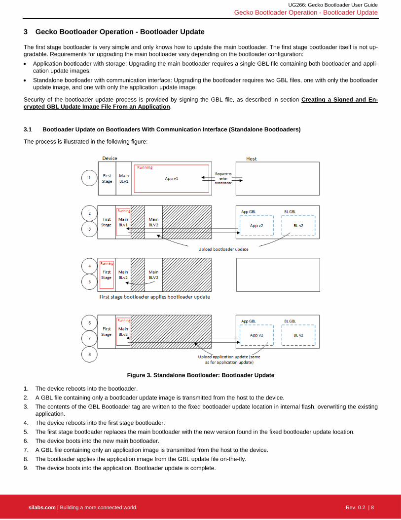
3.1 Bootloader Update on Bootloaders With Communication Interface (Standalone Bootloaders)
The process is illustrated in the following figure:
Figure 3. Standalone Bootloader: Bootloader Update
1. The device reboots into the bootloader.
2. A GBL file containing only a bootloader update image is transmitted from the host to the device.
3. The contents of the GBL Bootloader tag are written to the fixed bootloader update location in internal flash, overwriting the existing application.
4. The device reboots into the first stage bootloader.
5. The first stage bootloader replaces the main bootloader with the new version found in the fixed bootloader update location.
6. The device boots into the new main bootloader.
7. A GBL file containing only an application image is transmitted from the host to the device.
8. The bootloader applies the application image from the GBL update file on-the-fly.
9. The device boots into the application. Bootloader update is complete.

UG266: Gecko Bootloader User Guide
Gecko Bootloader Operation - Bootloader Update
silabs.com | Building a more connected world. Rev. 0.2 | 9
A bootloader update is started in the same way as an application update.
3.1.1 Downloading and Applying a Bootloader GBL Update File
When the bootloader has entered the receive loop, a GBL update file containing a bootloader update is transmitted to the bootloader. When a packet is received, it is passed to the image parser. The image parser parses the data, and returns bootloader update data in a callback. The bootloader core implements this callback, and flashes the data to internal flash at the fixed bootloader update address as given by the first stage bootloader.
The bootloader prevents a newly uploaded bootloader update image from being interpreted as valid by holding back parts of the boot-loader update vector table until the GBL file CRC and GBL signature (if required) have been verified.
When a complete bootloader update image is received, the main bootloader signals the first stage bootloader that it should enter firm-ware update mode by writing a command to the shared memory location at the bottom of SRAM, and then performing a software reset.
The first stage bootloader verifies the CRC of the bootloader update present in the bootloader update location in internal flash, and cop-ies the bootloader update over the main bootloader if the version number of the update is higher than the version number of the existing main bootloader.
3.1.2 Downloading and Applying an Application GBL Update File
Once the bootloader update is completed, the existing application is rendered invalid, since the bootloader update location overlaps with the application. A GBL update file containing an application update is transmitted to the bootloader. The application update process follows that in section Standalone Bootloader Operation.

UG266: Gecko Bootloader User Guide
Gecko Bootloader Operation - Bootloader Update
silabs.com | Building a more connected world. Rev. 0.2 | 10
3.2 Bootloader Update on Bootloaders With Storage (such as SoCs)
The process is illustrated in the following figure.
Figure 4. Application Bootloader: Bootloader Update
1. A single GBL file containing both a bootloader update image and an application image is downloaded onto the storage medium of the device (internal flash or external SPI flash).
2. The device reboots into the bootloader.
3. The main bootloader copies its update image into internal flash at the fixed bootloader update location, overwriting the existing application.
4. The device reboots into the first stage bootloader.
5. The first stage bootloader replaces the main bootloader with the new version.
6. The device boots into the new main bootloader.
7. The bootloader applies the application image from the GBL update file.
8. The device boots into the application. Bootloader update is complete.
A bootloader update is started in the same way as an Application Update. A single GBL file containing both a bootloader and an appli-cation update is written to storage by the application, and the bootloader is entered.
Applying a GBL Update File
The bootloader iterates over the list of storage slots marked for bootload, and attempts to verify the GBL file stored within. Verification returns information about whether the GBL file contains an application, or both a bootloader and an application. The image parser pars-es the file. If the GBL file contains a bootloader, the bootloader update data is returned in a callback. The bootloader core implements this callback, and flashes the data to internal flash at the bootloader update location given in the First Stage Bootloader Table.
The bootloader prevents a newly uploaded bootloader update image from being interpreted as valid by holding back parts of the boot-loader update vector table until the GBL file CRC and GBL signature (if required) have been verified.

UG266: Gecko Bootloader User Guide
Gecko Bootloader Operation - Bootloader Update
silabs.com | Building a more connected world. Rev. 0.2 | 11
The main bootloader signals the first stage bootloader that it should enter firmware update mode by writing a command to the shared memory location at the bottom of SRAM, and then performing a software reset.
The first stage bootloader verifies the CRC of the bootloader update present in the bootloader update location in internal flash, and cop-ies the bootloader update over the main bootloader if the version number of the update is higher than the version number of the existing main bootloader.
The new main bootloader is entered, and the images in the list of storage slots marked for bootload are verified. When the image parser parses the slot containing the GBL file with the bootloader + application update, the version number of the bootloader update is equal to the running main bootloader version, so another bootloader update will not be performed. Instead, the application update data are re-turned in a callback. Bootloading of the new application proceeds as described in section Application Bootloader Operation.

UG266: Gecko Bootloader User Guide
Getting Started with the Gecko Bootloader
silabs.com | Building a more connected world. Rev. 0.2 | 12
4 Getting Started with the Gecko Bootloader
This section describes how to build a Gecko Bootloader from one of the provided examples. The instructions assume that you have installed the protocol SDK and associated utilities as described in the SDK’s quick start guide, and that you are familiar with generating, compiling, and flashing an example application.
QSG106: Getting Started with EmberZNet PRO
QSG113: Getting Started with Silicon Labs Thread
QSG139: Bluetooth Development with Simplicity Studio
1. From the Launcher Perspective, click New Project.
2. In the Applications dialog, select Gecko Bootloader and click Next.

UG266: Gecko Bootloader User Guide
Getting Started with the Gecko Bootloader
silabs.com | Building a more connected world. Rev. 0.2 | 13
3. In the Select Application dialog, select your bootloader configuration example, and click Next.
4. In the Project Configuration dialog, name your project and optionally select a different project location. Click Next.

UG266: Gecko Bootloader User Guide
Getting Started with the Gecko Bootloader
silabs.com | Building a more connected world. Rev. 0.2 | 14
5. In the Project Setup dialog, if your part is not displayed, search for and select it. Select your compiler (in general, the same compiler you will use for the application). Click Finish. The Simplicity Studio IDE/AppBuilder perspective is displayed.
6. On the General tab, optionally enter a description.

UG266: Gecko Bootloader User Guide
Getting Started with the Gecko Bootloader
silabs.com | Building a more connected world. Rev. 0.2 | 15
The Plugins tab shows the configurations selected for the relevant example.
The Storage tab allows you to configure storage slots to be used if a storage plugin is enabled. The default configuration matches the target part and bootloader type.
7. Click Generate.
8. In the Generation Successful dialog, click OK.
9. Click the Build icon ( ). Two bootloader images are generated into the build directory: a main bootloader and a combined first stage and main bootloader. The main bootloader image is called <projectname>.s37, while the combined first stage + main boot-loader image is called <projectname>-combined.s37. The first time a device is programmed, whether during development or manufacturing, the combined image needs to be programmed. For subsequent programming, when a first stage bootloader is al-ready present on the device, the image containing only a main bootloader may be used. The image containing only a main boot-loader is also the image that must be used to create a GBL file for bootloader upgrade.
UG266: Gecko Bootloader User Guide
Configuring the Gecko Bootloader
silabs.com | Building a more connected world. Rev. 0.2 | 16
5 Configuring the Gecko Bootloader
5.1 Configuring Storage
Gecko Bootloaders configured as application bootloaders must include an API to store and access image files. This API is based on the concept of storage slots, where each slot has a predefined size and location in memory, and can be used to store a single update im-age. This is done by configuring the Storage plugins in the Bootloader application framework in Simplicity Studio.
When multiple storage slots are configured, a bootload list is used to indicate the order in which the bootloader should access slots to find update images. If multiple storage slots are supported, the application should write the bootload list by calling bootload-er_setBootloadList before rebooting into the bootloader to initiate a firmware update process. The bootloader attempts to verify the images in these storage slots in sequence, and applies the first image to pass verification. If only a single storage slot is supported, the bootloader uses this slot implicitly.
5.1.1 SPI Flash Storage Configuration
When configuring a Gecko Bootloader to obtain images from SPI flash, modify the following.
The base address of the storage area should be configured in the Common Storage plugin. This is the address at which the boot-loader places the bootload list, if more than one storage slot is configured. In the default configuration, this address is set to 0. If only a single storage slot is configured, the bootload list is not used, so configuring it may be omitted.
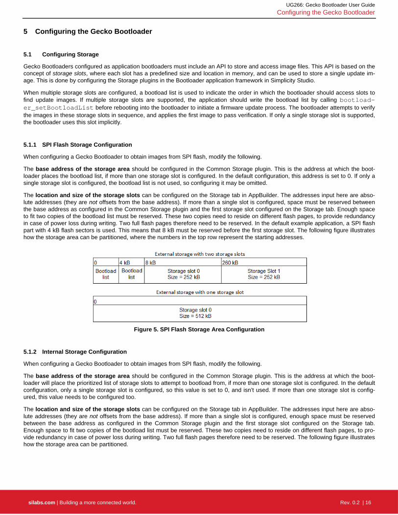
The location and size of the storage slots can be configured on the Storage tab in AppBuilder. The addresses input here are abso-lute addresses (they are not offsets from the base address). If more than a single slot is configured, space must be reserved between the base address as configured in the Common Storage plugin and the first storage slot configured on the Storage tab. Enough space to fit two copies of the bootload list must be reserved. These two copies need to reside on different flash pages, to provide redundancy in case of power loss during writing. Two full flash pages therefore need to be reserved. In the default example application, a SPI flash part with 4 kB flash sectors is used. This means that 8 kB must be reserved before the first storage slot. The following figure illustrates how the storage area can be partitioned, where the numbers in the top row represent the starting addresses.
Figure 5. SPI Flash Storage Area Configuration
5.1.2 Internal Storage Configuration
When configuring a Gecko Bootloader to obtain images from SPI flash, modify the following.
The base address of the storage area should be configured in the Common Storage plugin. This is the address at which the boot-loader will place the prioritized list of storage slots to attempt to bootload from, if more than one storage slot is configured. In the default configuration, only a single storage slot is configured, so this value is set to 0, and isn’t used. If more than one storage slot is config-ured, this value needs to be configured too.
The location and size of the storage slots can be configured on the Storage tab in AppBuilder. The addresses input here are abso-lute addresses (they are not offsets from the base address). If more than a single slot is configured, enough space must be reserved between the base address as configured in the Common Storage plugin and the first storage slot configured on the Storage tab. Enough space to fit two copies of the bootload list must be reserved. These two copies need to reside on different flash pages, to pro-vide redundancy in case of power loss during writing. Two full flash pages therefore need to be reserved. The following figure illustrates how the storage area can be partitioned.

UG266: Gecko Bootloader User Guide
Configuring the Gecko Bootloader
silabs.com | Building a more connected world. Rev. 0.2 | 17
Figure 6. Internal Storage Area Configurations
Note: the storage area partitioning in the example for two storage slots above does not take any NVM system into account. If using an NVM system like SimEE or PStore, take care to place and size the storage area in such a way that bootloader storage does not overlap with NVM.
5.2 Bootloader Example Configurations
The following sections describe the key configuration options for the example bootloader applications.
Note: Security features are disabled for all example configurations. In development, Silicon Labs strongly recommends enabling security features to prevent unauthorized parties from uploading untrusted program code. See the section Using Gecko Boot-loader Security Features to learn how to configure the security features of the Gecko Bootloader.
5.2.1 UART XMODEM Bootloader
Standalone bootloader for EmberZNet PRO, Silicon Labs Thread, and Silicon Labs Flex protocol stacks, using XMODEM-CRC over UART.
In this configuration, the XMODEM UART communication plugin, XMODEM parser plugin, and UART driver plugin are enabled. In order for the example application to run on a custom board, the GPIO ports and pins used for UART need to be configured. This is done by going to the Plugins tab of the AppBuilder project, and selecting the UART driver plugin. Here, Hardware Flow Control can be enabled or disabled, and the baud rate and pinout can be configured.
The GPIO activation plugin is also enabled by default, allowing bootloader entry into firmware upgrade mode by activating a GPIO through reset. This plugin can be disabled if this functionality is not desired, or the GPIO pin used for this can be configured under the GPIO Activation plugin on the Plugins tab.
5.2.2 BGAPI UART DFU Bootloader
Standalone bootloader for the Bluetooth protocol stack, using the BGAPI protocol for UART DFU. This bootloader should be used for all NCP-mode Bluetooth applications.
In this configuration, the BGAPI UART DFU communication plugin and UART driver plugin are enabled. In order for the example appli-cation to run on a custom board, the GPIO ports and pins used for UART need to be configured. This is done by going to the Plugins tab of the AppBuilder project, and selecting the UART driver plugin. Here, Hardware Flow Control can be enabled or disabled, and the baud rate and pinout can be configured.
The GPIO activation plugin is also enabled by default, allowing bootloader entry by activating a GPIO through reset. This plugin can be disabled if this functionality is not desired, or the GPIO pin used for this can be configured under the GPIO Activation plugin on the Plugins tab.

UG266: Gecko Bootloader User Guide
Configuring the Gecko Bootloader
silabs.com | Building a more connected world. Rev. 0.2 | 18
5.2.3 EZSP SPI Bootloader
Standalone bootloader for EmberZNet PRO, Silicon Labs Thread, and Silicon Labs Flex protocol stacks using EZSP for SPI.
In this configuration, the EZSP SPI communication plugin, XMODEM parser plugin, and SPI slave driver plugin are enabled. In order for the example application to run on a custom board, the GPIO ports and pins used for SPI and EZSP signaling need to be configured. This is done by going to the Plugins tab of the AppBuilder project, and selecting the SPI slave and EZSP SPI plugins respectively.
5.2.4 SPI Flash Storage Bootloader
Application bootloader for all wireless protocol stacks, using an external SPI flash to store update images received over the air by the application.
In this configuration, the SPI flash and common storage plugins, as well as the SPI driver plugin, are enabled. In order for the example application to run on a custom board, the GPIO ports and pins used for SPI communication with the external flash need to be config-ured in the SPI plugin, and the type of SPI flash needs to be configured in the SPI flash plugin. The base address of the storage area can be configured in the Common Storage plugin. The location and size of the storage slots themselves can be configured on the Stor-age tab in AppBuilder.
5.2.5 Internal Storage Bootloader
Application bootloader for all wireless protocol stacks, using internal flash to store update images received over the air by the applica-tion. This example is designed for EFR32xG12. The layout of the storage should be modified before running the bootloader on any oth-er devices. In this configuration, the internal flash and common storage plugins are enabled. The base address of the storage area is configured in the Common Storage plugin. The location and size of the storage slots can be configured on the Storage tab in AppBuild-er. In the default example application, a single storage slot is configured.
5.2.6 Bluetooth In-Place OTA DFU Bootloader
Application bootloader for in-place over-the-air device firmware update with the Bluetooth protocol stack, using internal flash to store stack and application update images received over the air in a two-stage process. This example is designed for use with EFR32BG1 (256 kB flash) only.
In this configuration, the 256 kB internal flash is configured as follows.
Figure 7. Flash Configuration in Bluetooth In-Place OTA DFU Bootloader
The first 16 kB are reserved for bootloader and the last 4 kB are used by Persistent Storage (PS). The size of these two are fixed. One continuous area between the bootloader and PS is used by the Bluetooth stack and user application. The size of this area is (256 – 16 – 4) = 236 kB. This area is split equally between the Bluetooth stack and the user application, meaning that the maximum size for both the stack and application is 236/2 = 118 kB.
In a Bluetooth in-place OTA DFU Bootloader project one storage slot is defined as follows:
Start at offset 0x21800 (137216)
Size: 0x1D800 (120832 bytes)

UG266: Gecko Bootloader User Guide
Simplicity Commander and the Gecko Bootloader
silabs.com | Building a more connected world. Rev. 0.2 | 19
6 Simplicity Commander and the Gecko Bootloader
Simplicity Commander is a single, all-purpose tool to be used in a production environment. It is invoked using a simple CLI (Command Line Interface that is also scriptable. You can use Simplicity Commander to perform these essential tasks:
Generating keyfiles for signing and encryption
Signing application images for Secure Boot
Creating GBL images (encrypted or unencrypted, signed or unsigned)
Parsing GBL images
Simplicity Commander is used throughout the examples in the following sections. For more information on executing the commands to complete these tasks, refer to UG162: Simplicity Commander Reference Guide.
Note: Simplicity Commander offers a GUI (Graphical User Interface) that can be used in the lab for typical tasks such as flashing device images. The functions in this User Guide are performed from the CLI.
UG266: Gecko Bootloader User Guide
Gecko Bootloader Security Features
silabs.com | Building a more connected world. Rev. 0.2 | 20
7 Gecko Bootloader Security Features
7.1 About Security Features
The Gecko Bootloader can enforce security on two levels:
Secure Boot refers to the verification of the authenticity of the application image in main flash on every boot of the device.
Secure Firmware Update refers to the verification the authenticity of an update image before performing a bootload, and optionally enforcing that update images are encrypted.
7.1.1 Secure Boot Procedure
When Secure Boot is enabled, the cryptographic signature of the application image in flash is verified on every boot, before the applica-tion is allowed to run. Secure Boot is enabled by default, and Silicon Labs recommends using it to ensure the validity and integrity of firmware images.
Signature Algorithms
The Gecko Bootloader supports the ECDSA-P256-SHA256 cryptographic signature algorithm. This is the ECDSA (elliptical curve digital signature algorithm) of the SHA-256 digest of the application firmware image, using the NIST P-256 (secp256r1) curve.
Summary of Operation
1. On boot, the bootloader checks the application image for information about whether it is signed.
2. The type of signature and signature location is determined.
3. If the type of signature does not match the requirements of the bootloader, the bootloader enters device firmware update mode and prevents the application from running.
4. According to the chosen signature algorithm, the signature of the contents of flash from the beginning of the application to the loca-tion of the signature is compared to the signature at the signature location.
5. If the signatures do not match, the bootloader enters device firmware update mode and prevents the application from running.
Secure Boot using ECDSA-P256-SHA256
For an image to be signed for Secure Boot, the application needs to contain a copy of the ApplicationProperties_t struct. This struct contains information about which signature algorithm is used, and where to find the signature.
On every boot, the bootloader calculates the SHA-256 digest of the application image, from the beginning of the application to the start of the signature. The signature of the SHA-256 digest is then verified using ECDSA-P256.
If the signature is valid, the application is allowed to boot. Else, the bootloader is entered, and an application update is attempted if one is available.
The public key used for signature verification is stored as a manufacturing token in the device. Simplicity Commander can be used to generate a key pair and write the public key to the device. See AN961: Bringing up Custom Devices for the Mighty Gecko and Flex Gecko Families for more information.
7.1.2 Secure Firmware Update
The Gecko Bootloader supports a secure firmware update process. This is achieved by using symmetric encryption to encrypt the up-date image, and asymmetric cryptography to sign the update image in order to ensure its integrity and authenticity.
Encryption Algorithms
The Gecko Bootloader supports the AES-CTR-128 encryption algorithm. The GBL update file is encrypted using 128-bit AES in Coun-ter mode with a random nonce as the initial counter value.
Signature Algorithms
The Gecko Bootloader supports the ECDSA-P256-SHA256 cryptographic signature algorithm. This is the ECDSA signature of the SHA-256 digest of the GBL update file, using the NIST P-256 (secp256r1) curve.

UG266: Gecko Bootloader User Guide
Gecko Bootloader Security Features
silabs.com | Building a more connected world. Rev. 0.2 | 21
Summary of Operation
Before starting a firmware update process, the application can verify an image in storage by calling into the bootloader verification func-tions.
During firmware update, the GBL file is parsed, and if encrypted, decrypted on-the-fly. A GBL Signature Tag in the GBL file indicates to the bootloader that the file is signed, and the signature is verified. If signature verification fails, the firmware update process is aborted.
7.2 Using Gecko Bootloader Security Features
In this example, we assume that a bootloader called bootloader-uart-xmodem has been built using the Application Builder in Simplici-ty Studio. In the output directory, two files of interest have been generated:
bootloader-uart-xmodem.s37 – This file contains the main bootloader. Can be used for bootloader update.
bootloader-uart-xmodem-combined.s37 – This file contains both the first stage and main bootloader in a single image. Can be used for manufacturing and initial deployment of the bootloader.
The relevant version can be flashed to the EFR32 using the Flash Programmer in Simplicity Studio, or using Simplicity Commander.
This example provides two ways of signing the update images. The first option uses Simplicity Commander to generate key material and sign data. This is suitable for development. The second option uses an external signer, such as a dedicated Hardware Security Module (HSM) to protect private key material and perform signing operations. Silicon Labs recommends using a HSM to safeguard private keys.
7.2.1 Generating Keys
In order to use the security features of the Gecko Bootloader, encryption and signing keys need to be generated. These keys must then written to the EFR32 device. The encryption key is used with the GBL file for secure firmware update. The signing keys are used both with the GBL file for secure firmware update and to sign the application image for Secure Boot.
Generating a Signing Key Using Simplicity Commander
commander gbl keygen --type ecc-p256 -o signing-key
This creates an ECDSA-P256 key pair for signing: signing-key contains the private key in PEM format, and must be kept secret from third parties. This key will later be used to sign images and GBL files. signing-key.pub contains the public key in PEM format, and can be used to verify GBL files using commander gbl parse. signing-key-tokens. txt contains the public key in token format, suitable for writing to the EFR32 device.
Generating a Signing Key Using a Hardware Security Module
When using a Hardware Security Module, the private key is kept secret inside the HSM. According to the instructions from your HSM vendor, have it generate an ECDSA-P256 key pair and export the public key in PEM format to the file signing-key.pub. Then use Sim-plicity Commander to convert the key to token format, suitable for writing to the EFR32 device.
commander gbl keyconvert --type ecc-p256 signing-key.pub –o signing-key-tokens.txt
Generating an Encryption Key
commander gbl keygen --type aes-ccm -o encryption-key
This creates an AES-128 key for encryption in the file encryption-key. The file has token format, making it suitable to write to the EFR32 device using commander flash --tokenfile.
Writing Keys to the Device
To write the two token files containing the encryption key and public key as manufacturing tokens to the device, issue the following command:
commander flash --tokengroup znet --tokenfile encryption-key --tokenfile signing-key-tokens.txt

UG266: Gecko Bootloader User Guide
Gecko Bootloader Security Features
silabs.com | Building a more connected world. Rev. 0.2 | 22
7.2.2 Signing an Application Image for Secure Boot
If the bootloader enforces Secure Boot, the application needs to be signed in order to pass verification. On every boot, an SHA-256 digest of the application is calculated. The signature is verified using ECDSA-P256, with the same public key as for the GBL file signing. Signature verification failure prevents application from booting.
Using Simplicity Commander
Signing the application can be done with the command:
commander convert myapp.s37 --secureboot --keyfile signing-key -o myapp-signed.s37
Using a Hardware Security Module
The application can be prepared for signing by issuing the command:
commander convert myapp.s37 --secureboot --extsign -o myapp-for-signing.s37
Using a HSM, sign the output file myapp-for-signing.s37, and supply the resulting DER-formatted signature file signature.der back to Simplicity Commander:
commander convert myapp.s37 --secureboot --signature signature.der –o myapp-signed.s37
7.2.3 Creating a Signed and Encrypted GBL Update Image File From an Application
To create a GBL file from an application, use commander gbl create.
Note that, as of this writing, secure application images can only be constructed through Simplicity Commander, not through the configu-ration options available through AppBuilder.
Using Simplicity Commander to Sign
For an application called myapp.s37, use:
commander gbl create myapp.gbl --app myapp.s37 --secureboot --signgbl --signingkey signing-key --encrypt encryption-key
This single command performs four actions:
Signs the application for Secure Boot
Creates a GBL file
Encrypts the GBL file
Signs the GBL file
If the application was previously signed using commander convert --secureboot, remove the --secureboot parameter from the commander gbl create command.
Using a Hardware Security Module to Sign
For an application called myapp-signed.s37, which has previously been signed for Secure Boot, use:
commander gbl create myapp-for-signing.gbl --app myapp-signed.s37 --signgbl --extsign --encrypt en-cryption-key
This command performs the following actions:
Creates a GBL file
Encrypts the GBL file
Prepares the GBL file for signing by an external signer
Using a HSM, sign the output file myapp-for-signing.gbl, and supply the resulting DER-formatted signature file signature.der back to Simplicity Commander:
commander gbl sign myapp-for-signing.gbl --signature signature.der -o myapp.gbl

UG266: Gecko Bootloader User Guide
Application Interface
silabs.com | Building a more connected world. Rev. 0.2 | 23
8 Application Interface
The bootloader has an application interface exposed through a function table in the bootloader. The application interface provides APIs to use bootloader functions for storing and retrieving update images, and verifying their integrity. APIs to reboot into the bootloader are also provided. For details see the Gecko Bootloader API Reference, shipped with the SDK in the platform/bootloader/documentation folder.
If you are not using a protocol stack from Silicon Labs, the api/btl_interface.h header provides the bootloader application interface API. If you are using a protocol stack from Silicon Labs, the recommended bootloader interface API for the specific protocol stack should be used instead. The following files provide the implementation of the bootloader interface:
api/btl_interface.c (common interface)
api/btl_interface_storage.c (interface to storage functionality)
The application interface consists of functions that can be included into the customer application, and that communicate with the boot-loader through the MainBootloaderTable_t. This table contains function pointers into the bootloader. The 10th word of the bootloader contains a pointer to this structure, allowing any application to easily locate it. Using the wrapper functions provided in the Bootloader Interface API is preferred over accessing the bootloader table directly. Modules include:
Application Parser Interface: Application interface for interfacing with the bootloader image parser.
Application Storage Interface: Application interface for interfacing with the bootloader storage. The Storage Interface is only available on bootloaders that support the storage interface.
Common Application Interface: Generic application interface available on all versions of the bootloader, independently of which plugins are present.
8.1 Application Properties
Applications must contain an ApplicationProperties_t struct declaring the application version, capabilities, and so on. When using a protocol stack from Silicon Labs, this structure is already present in the application. Simplicity Commander extracts the metadata con-tained in this structure from the application and places it in the GBL update file.
The structure is also used to declare whether the application image is signed, and what type of signature is used. This information is added by Simplicity Commander when signing the image. In order for the bootloader to locate the ApplicationProperties_t struct, if not already done by the linker, Simplicity Commander modifies word 13 of the application to insert a pointer to the ApplicationProper-ties_t struct when signing the application image for Secure Boot and creating the GBL file.

UG266: Gecko Bootloader User Guide
Using the Gecko Standalone Bootloaders with EmberZNet PRO and Silicon Labs Thread
silabs.com | Building a more connected world. Rev. 0.2 | 24
9 Using the Gecko Standalone Bootloaders with EmberZNet PRO and Silicon Labs Thread
A Gecko Bootloader-based standalone bootloader receives an application image onto a target device by serial transfer via SPI or UART. If using UART, you can establish a serial connection between a source device and a target device’s serial interface and upload a new software image to it using the XModem protocol. If you need information on the XModem protocol, a good place to start is http://en.wikipedia.org/wiki/ XMODEM, which should have a brief description and up-to-date links to protocol documentation.
9.1 Performing a Serial Upload – UART XMODEM Bootloader
Serial upload can be performed with any source device that provides the expected serial interface method. This can be a Windows- based PC, a Linux or Mac OS-based device, or an embedded MCU with no operating system. UART transfer can be done with a third-party serial terminal program like Windows HyperTerminal or Linux “lrzsz” or with user-compiled host code. However, drivers for SPI Master or UART may vary with operating systems, and serial terminal programs may vary in timing and performance, so if you are un-sure about what driver or program to use on your source code, please consult Silicon Labs technical support.
To open a serial connection over UART, the source device connects to the target device at 115,200 baud, 8 data bits, no parity bit, and 1 stop bit (8-N-1), with no flow control by default. These options may be changed using the plugin options in the Bootloader AppBuilder project.
Note: The UART-based serial bootloader configuration do not employ any flow control in the communication channel by default, be-cause the XModem protocol used for image transfer already has built-in flow control mechanisms. However, Silicon Labs’ normally-supplied NCP firmware does utilize either hardware-based (RTS/CTS) or software-based (XON/XOFF) flow control, so a host device must take care to temporarily disable the flow control when placing its NCP into serial bootloading mode. Al-ternatively, application designers can change the options in the provided bootloader project and customize the serial bootload-er’s handling of the UART to add hardware flow control at their discretion.
Once the connection with a UART-based serial bootloader is established:
1. The target device’s bootloader sends output over its serial port after it receives a carriage return from the source device at the ex-pected baud rate. This prevents the bootloader from prematurely sending commands that might be misinterpreted by other devices that are connected to the serial port. Note that serial bootloaders typically don’t enforce any timeout when awaiting the initial serial handshake via carriage return, so the bootloader will wait indefinitely in this mode until guided by the source device or until the chip is reset.
2. After the bootloader receives a carriage return from the target device, it displays a menu with the following ASCII-based output:
1. upload gbl 2. run 3. ebl info BL >
Note: While current menu options should remain functionally unchanged, the menu title and options text is liable to change, and new options might be added.
After listing the menu options, the bootloader's “BL >” prompt displays, and the ASCII character corresponding to the number of each option can then be entered by the source to select the described action, such as ‘2’ (ASCII code 0x32) to run the firmware presently loaded in the application area. Here again, no timeout is enforced by the bootloader, so it will wait indefinitely until a character is re-ceived or the chip is reset. Note that while the menu interface is designed for human interaction, the transfer can still be performed pro-grammatically or through a scripted interface, provided the source device sends the expected ASCII characters to the target at appro-priate times.
Note: Scripts that interact with the bootloader should use only the “BL >” prompt to determine when the bootloader is ready for input.
Selecting menu option 1 initiates upload of a new software image to the target device, which unfolds as follows:
1. The target device awaits an XModem CRC upload of a GBL file over the expected serial interface, as indicated by the stream of C characters that its bootloader transmits.
2. If no transaction is initiated within 60 seconds, the bootloader times out and returns to the menu.
3. Once uploading begins (first XModem SOH data packet received), the bootloader expects each successive XModem SOH packet within 1 second, or else a timeout error will be generated and the session will abort.
4. After an image successfully uploads, the XModem transaction completes and the bootloader displays ‘Serial upload complete’ be- fore redisplaying the menu.

UG266: Gecko Bootloader User Guide
Using the Gecko Standalone Bootloaders with EmberZNet PRO and Silicon Labs Thread
silabs.com | Building a more connected world. Rev. 0.2 | 25
9.2 Performing a Serial Upload - SPI
To open a serial connection over SPI, the source device must act as SPI Master using Mode 0 or Mode 2. It must also react to edge- triggered interrupts from the slave device using the same nHOST_INT logic and SPI framing as the EZSP-SPI protocol described in AN711: EZSP-SPI Host Interfacing Guide.
Note: This SPI protocol differs slightly from the SPI protocol used for Thread NCP/host communication, but the same SPI standalone bootloader can be used with Thread NCPs as well as EZSP NCPs as the host-side bootloading code.
Once the SPI slave enters bootloader mode, which includes a reset sequence with host interrupt and Reset response frame similar to the reset sequence of a normal EZSP-SPI NCP, the bootloader sits in a Waiting state looking for SPI input in the form of bootloader packets (SPI bootloader frames with 0xFD SPI byte). The source device then must perform a bootloader Query transaction, which in-volves the source sending a Query packet and expecting a Response packet. Note that the first Query transaction yields a Query- Found result (status byte 0x1A), while the subsequent Query will yield the expected Response result (status byte ‘R’ or 0x52). For de- tails, refer to the sample SPI bootloading process described in section Sample EZSP-SPI Bootloader Transcript.
Once a query transaction has completed successfully, that is with expected Response frame, the transfer of data packets can begin. The transfer process follows standard XModem-CRC protocol, just like the UART -based serial bootloader uses, but with SPI framing similar to that used to encapsulate EZSP data frames. This SPI-based XModem adaptation adheres to the following rules, some of which may differ from the SPI protocol used by the normal EZSP NCP firmware:
The 0xFD SPI byte and a length byte (for number of bytes to follow) prefix every command or response frame.
The 0xA7 frame terminator byte concludes every SPI command or response frame. This byte is not included in the length count used in the length byte.
The NCP operates as a SPI slave, so nSSEL must be asserted before each transaction.
No EZSP frame control bytes are used in the SPI frame. Consequently, no sleep mode operation is supported by the target during the bootload.
SPI timing (timeouts, signal transitions) are similar to EZSP. See AN711: EZSP-SPI Host Interfacing Guide for details.
The nHOST_INT signal is asserted by the target to indicate a pending response.
In place of the EZSP “callbacks” command, the host should use the bootloader’s Query packet to prompt the target to push the asynchronous response such as XModem ACK back to the host.
Each SPI frame typically generates an initial, synchronous response from the target, such as a BLOCKOK status, and a follow-up, asynchronous response, which must be queried for by the host. For example, the EOT packet generates a synchronous response with FILEDONE status, then Query transaction yields XModem ACK with block number of lastBlock+1 before rebooting into new firmware.
The host must wait for nHOST_INT to assert (become low) before querying for status, as the SPI bootloader is edge-triggered ra-ther than level triggered. Thus, acting too fast at the host side can cause an edge transition to be missed and the bootloading state machines at the host and NCP to get out of synchronization, resulting in problems later on.
SPI Status and SPI Version commands (SPI bytes 0x0A and 0x0B) are still supported.
Prior to the first data block being processed, the SPI bus is polled at a rate of once per second.
Once the data transmission begins (first block processed), the bootloader will wait up to 60 seconds for the next data packet, polling at 5-second intervals.
If either of the timeouts above is exceeded, the bootloader signals a cancellation (CAN frame) and reboots, restarting the state ma-chine.
XModem data packets consist of:
The SOH byte (ASCII 0x01) A 1-byte incrementing block number (beginning at 1 and wrapping back around from 255 to 0) The block number’s complement 128 bytes of data read directly from the GBL file being uploaded A 16-bit CRC of the data bytes from that packet
Each packet is followed by an XModem ACK or NAK from the target device (the NCP running the bootloader), which confirms or refutes the current data packet.
If the target receives a duplicate block, it simply sends the ACK for that block again. If the target receives a block that had an XModem frame error (such as bad CRC), the bootloader expects that data block to be retransmitted and then the bootload can con-tinue. Other kinds of errors are considered unrecoverable and cause the bootload to abort.
If the bootload process aborts for any reason (including receiving an XModem Cancel (CAN) frame from the source), an XModem Cancel frame is echoed on the SPI interface from the target and the target then reboots, restarting the bootloader state machine.

UG266: Gecko Bootloader User Guide
Using the Gecko Standalone Bootloaders with EmberZNet PRO and Silicon Labs Thread
silabs.com | Building a more connected world. Rev. 0.2 | 26
When the source device reaches the last XModem data block, it should be padded to 128 bytes of data using SUB (ASCII 0x1A) characters.
Once the last block is ACKed by the target, the transfer should be finalized by an EOT (ASCII 0x04) packet from the source. Once this packet is confirmed via XModem ACK from the target, the device reboots, causing the new firmware to be launched.
Note: The ACK for the last XModem data packet may take much longer (1-3 seconds) to be received than prior data packets. This is due to the CRC32 checksum and optional GBL file signature verification being performed across the received GBL file data before sending the ACK. The source device must ensure that its SPI XModem state machine waits a sufficient amount of time to allow this checksum process to occur without timing out on the response just before the EOT is sent.
9.3 Sample EZSP-SPI Bootloader Transcript
The following is a record of the SPI frames transmitted and received by the EZSP-SPI host during the SPI bootload process, as cap-tured from an EZSP Host application running the ota-bootload-ncp-spi.c state machine from the EmberZNet Application Framework’s OTA Platform Bootloader plugin with an EZSP-SPI NCP device as target using the ezsp-spi-bootloader.
A “TX:” line means that the hexadecimal byte values contained in brackets (“[ … ]”) are transmitted by the source via SPI to the target. An “RX:” line means that the byte values that follow in brackets are received by the source via SPI from the target NCP device.
Note: Firmware data (in the form of an EBL file for an EZSP-SPI NCP) is being streamed to the host’s UART (for relaying down to the target) during this process, but that serial stream is not shown here.
Comments about the process are indicated in italics and are not part of the data transmitted on the SPI bus.
Check to make sure NCP booted properly into bootloader... TX: [0B A7] TX: [0B A7] TX: [0A A7] TX: [FD 01 51 A7] RX: [FD 01 1A A7] TX: [FD 01 51 A7] RX: [FD 1A 52 01 FF FF 64 65 76 30 34 37 31 00 FF FF FF FF FF FF FF FF 00 02 02 02 20 0A A7] TX: [FD 01 51 A7] RX: [FD 01 1A A7] TX: [FD 01 51 A7] RX: [FD 1A 52 01 FF FF 64 65 76 30 34 37 31 00 FF FF FF FF FF FF FF FF 00 02 02 02 20 0A A7] Starting SPI bootloading... TX: [FD 01 51 A7] RX: [FD 01 1A A7] TX: [FD 01 51 A7] RX: [FD 1A 52 01 FF FF 64 65 76 30 34 37 31 00 FF FF FF FF FF FF FF FF 00 02 02 02 20 0A A7] TX: [FD 85 01 01 FE 00 00 00 3C 14 20 E2 60 48 7E AA 56 42 50 7C 53 0A 71 77 77 FF FF FF FF FF FF 78 61 70 32 62 2D 65 6D 32 36 30 2D 65 6D 32 35 30 2D 64 65 76 30 34 37 30 00 00 00 00 00 00 00 80 ED 3A AA FD 03 21 00 02 E0 00 04 57 40 00 00 3B E0 00 00 05 00 A1 E0 14 40 CA B7 E0 32 05 38 1E 05 92 6C 00 02 80 0B 54 A7] RX: [FD 01 19 A7] TX: [FD 01 51 A7] RX: [FD 03 06 01 00 A7] TX: [FD 85 01 02 FD FF FF FF FF FF FF FF FF FF FF FF FF FF FF FF FF FF FF FF FF FF FF FF FF FF FF FF FF FF FF FF FF FF FF FF FF FF FF FF FF FF FF FF FF FF FF FF FF FF FF FF FF FF FF FF FF FF FF FF FF FF FF FF FF FF FF FF FF FF FF C0 1B 48 00 00 2B 20 C8 0A F0 C0 1B 01 00 C0 C8 04 F0 00 04 01 00 91 E0 01 00 89 E0 C0 DB C0 2B FA 00 40 19 01 38 FA 00 40 29 FA 00 41 89 03 E4 FA 00 41 29 46 00 7A DB A7] RX: [FD 01 19 A7] TX: [FD 01 51 A7] RX: [FD 03 06 02 00 A7] TX: [FD 85 01 03 FC 18 99 75 F4 C4 27 C6 23 C8 02 CA 03 CC 2F 7A 00 3E 15 DC 27 46 00 1A 15 CE 27 00 14 D8 27 7A 00 3E 25 46 00 00 15 CE C7 D8 B7 56 F4 00 10 D6 27 02 C4 03 00 49 F0 02 B0 D6 17 80 00 00 C4 03 00 D3 F0 80 00 00 B0 D6 17 40 00 00 C4 02 00 68 F0 40 00 00 B0 D6 17 04 00 00 C4 77 F0 04 00 00 B0 D6 17 20 0C 20 0F 00 00 00 B0 D6 17 10 00 00 C4 02 00 96 F0 10 00 00 B0 D6 17 08 00 C4 1E A7] RX: [FD 01 19 A7] TX: [FD 01 51 A7] RX: [FD 03 06 03 00 A7]

UG266: Gecko Bootloader User Guide
Using the Gecko Standalone Bootloaders with EmberZNet PRO and Silicon Labs Thread
silabs.com | Building a more connected world. Rev. 0.2 | 27
TX: [FD 85 01 04 FB 00 C4 03 00 B6 F0 08 00 00 B0 D6 17 02 00 00 C4 01 00 92 F0 02 00 00 B0 D6 17 01 00 00 C4 01 00 C3 F0 01 00 00 B0 D6 17 40 C4 01 00 38 F0 40 B0 D6 17 20 C4 01 00 F0 F0 20 B0 D6 17 10 C4 02 00 F7 F0 10 B0 D6 17 04 C4 03 00 D0 F0 D6 27 CE D7 CE 27 D6 17 19 E0 CE 17 46 00 1A 25 CC 1F DC 17 7A 00 3E 25 CA 07 C8 06 C6 13 C4 17 01 58 FA 00 40 29 C0 1B 05 EC C0 00 A7] RX: [FD 01 19 A7] TX: [FD 01 51 A7] RX: [FD 03 06 04 00 A7] 250 more data block transmissions follow; omitted here for brevity. The frames following immediately below illustrate how the sequence number wraparound condition is handled... TX: [FD 85 01 FE 01 22 17 24 57 2C C5 EA 25 20 17 24 37 EA 11 FC 3C FF 00 B1 9C 04 3C 28 3C FE E3 FE 2B F4 27 F6 23 C4 3C 1E 00 6D 9C 34 27 3E 17 FE 27 3C 17 FC 27 FE 2D FE 15 20 34 30 13 FC 3C FF 00 11 9C 40 37 2C C5 04 3C 36 27 34 13 2C 81 03 F0 30 13 34 23 79 00 5E 19 34 3B 80 00 00 16 04 54 2C C5 38 27 00 14 FE 27 04 14 FC 27 38 17 FA 27 FE 2D FE 15 10 34 34 13 FA 3C 58 9D 3A 17 3E 13 06 3C 20 00 83 32 A7] RX: [FD 01 19 A7] TX: [FD 01 51 A7] RX: [FD 03 06 FE 00 A7] TX: [FD 85 01 FF 00 C0 9C FE 00 C6 15 0F F4 FE 2D FE 15 20 34 FE 27 00 14 FC 27 FE 2D FE 15 10 34 04 10 FC 3C FE 00 6A 9C 04 3C FE 00 C6 15 0B F4 FE 2D FE 15 20 34 FE 27 30 17 36 13 FE 3C FE 00 C4 9C 02 3C E2 2D E2 15 FE 27 FE 2D FE 15 20 34 FC 27 00 14 FA 27 F8 27 36 17 F6 27 32 17 F4 27 30 17 00 10 F4 3C FD 00 F9 9C 04 14 0A 27 FE 2D FE 11 0C 30 FE 2D FE 15 1C 34 0A 3C 44 9D 02 3C 00 84 03 F0 01 14 79 65 A7] RX: [FD 01 19 A7] TX: [FD 01 51 A7] RX: [FD 03 06 FF 00 A7] TX: [FD 85 01 00 FF 02 E0 00 14 3C 3C FE E3 FE 2B 10 14 42 00 18 25 42 00 44 15 01 B4 42 00 44 25 46 00 1A 15 08 B5 46 00 1A 25 6F 00 80 14 42 00 02 25 42 00 00 25 42 00 02 15 1F 34 42 00 02 25 01 14 42 00 18 25 7E 00 D8 25 6F 00 80 5 42 00 04 25 42 00 06 15 1F 34 18 25 00 14 7E 00 DA 25 01 14 F00 DC 25 FE E3 FE 2B FC 27 00 14 94 25 FA 00 9D 93 A7] RX: [FD 01 19 A7] TX: [FD 01 51 A7] RX: [FD 03 06 00 00 A7] TX: [FD 85 01 01 FE DC 25 41 00 2E 25 32 00 64 14 41 00 2C 25 15 14 42 00 48 25 60 00 664 41 00 40 25 58 14 41 00 42 25 03 14 41 00 44 25 00 26 25 28 14 41 00 38 25 55 14 41 00 34 25 ED 00 80 14 41 00 3A 25 09 14 41 00 3E 25 1F 14 41 00 30 25 0E 15 FA 27 0E 11 11 14 FA 3C 50 9D 7A 00 D8 15 02 3C 0C 00 4C 9C 40 14 42 00 44 25 03 14 42 00 42 25 41 00 4A 25 FA 00 0E DE A7] RX: [FD 01 19 A7] TX: [FD 01 51 A7] RX: [FD 03 06 01 00 A7] TX: [FD 85 01 02 FD D6 15 0D 00 B0 9C 00 84 06 F4 01 00 2D 10 03 00 24 14 46 9D FA 00 D7 11 08 A0 08 A4 E2 21 E2 15 0D 00 47 9C 01 14 41 00 46 25 18 00 00 14F 00 B2 9C FF 10 FF 14 0F 00 A8 01 A2 E_00 7C 9C 01 14 0F 00 90 9C 01 14 41 00 14 25 46 00 1A 15 06 B5 46 00 1A 25 04 00 F3 14 46 00 1E 0 1C 25 FF 00 4D 9C 00 14 04 3C F 0F 42 _B A7] RX: [FD 01 19 A7] TX: [FD 01 51 A7] RX: [FD 03 06 02 00 A7] 826 more data block transmissions follow; omitted here for brevity. The frames following immediate-ly below illustrate how the last data block is padded to 128 bytes and how the transmission is con-cluded successfully with the EOT and a final query transaction... TX: [FD 85 01 3F C0 01 00 01 00 FF FF FF 00 FF 00 FF 00 AB CD C1 10 FF 00 FC 04 00 04 5A 0C BA B8 FF FF FF FF FF FF FF FF FF FF FF FF FF FF FF FF FF FF FF FF FF FF FF FF FF FF FF FF FF FF FF FF FF FF FF FF FF FF 1A 1A 1A 1A 1A 1A 1A 1A 1A 1A 1A 1A 1A 1A 1A 1A 1A 1A 1A 1A 1A 1A 1A 1A 1A 1A 1A 1A 1A 1A 1A 1A 1A 1A 1A 1A 1A 1A 1A 1A 1A 1A 1A 1A 1A 1A 1A 1A 1A 1A 1A 1A 1A 1A 1A 1A 1A 1A 1A 1A 1A 1A 1A 1A 9F 61 A7] RX: [FD 01 19 A7]
UG266: Gecko Bootloader User Guide
Using the Gecko Standalone Bootloaders with EmberZNet PRO and Silicon Labs Thread
silabs.com | Building a more connected world. Rev. 0.2 | 28
TX: [FD 01 51 A7] RX: [FD 03 06 3F 00 A7] TX: [FD 01 04 A7] RX: [FD 01 17 A7] TX: [FD 01 51 A7] RX: [FD 03 06 40 00 A7] NCP resets back into EZSP at this point, so normal reset sequence occurs and frames begin to use 0xFE as SPI byte... TX: [0B A7] TX: [0B A7] TX: [0A A7] TX: [0B A7] TX: [0B A7] TX: [0A A7] TX: [FE 04 07 00 00 02 A7] RX: [FE 07 07 80 00 02 02 40 32 A7] TX: [FE 04 08 00 52 01 A7]
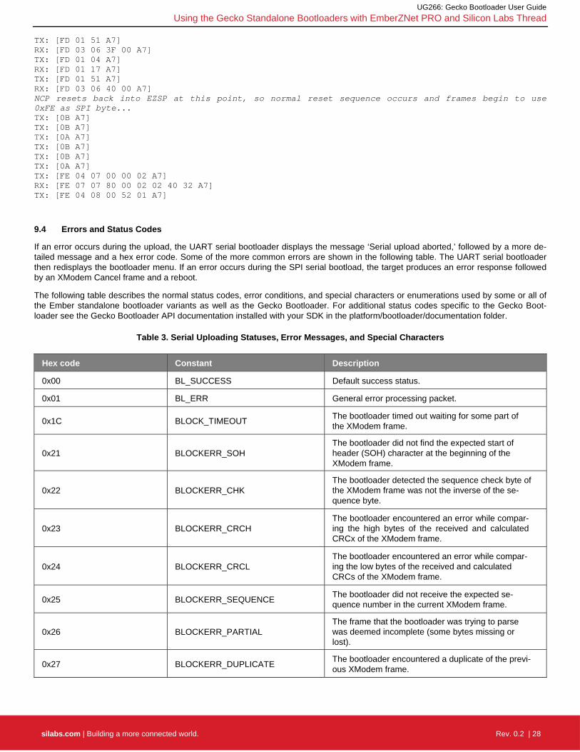
9.4 Errors and Status Codes
If an error occurs during the upload, the UART serial bootloader displays the message ‘Serial upload aborted,’ followed by a more de-tailed message and a hex error code. Some of the more common errors are shown in the following table. The UART serial bootloader then redisplays the bootloader menu. If an error occurs during the SPI serial bootload, the target produces an error response followed by an XModem Cancel frame and a reboot.
The following table describes the normal status codes, error conditions, and special characters or enumerations used by some or all of the Ember standalone bootloader variants as well as the Gecko Bootloader. For additional status codes specific to the Gecko Boot-loader see the Gecko Bootloader API documentation installed with your SDK in the platform/bootloader/documentation folder.
Table 3. Serial Uploading Statuses, Error Messages, and Special Characters
Hex code Constant Description
0x00 BL_SUCCESS Default success status.
0x01 BL_ERR General error processing packet.
0x1C BLOCK_TIMEOUT The bootloader timed out waiting for some part of the XModem frame.
0x21 BLOCKERR_SOH The bootloader did not find the expected start of header (SOH) character at the beginning of the XModem frame.
0x22 BLOCKERR_CHK The bootloader detected the sequence check byte of the XModem frame was not the inverse of the se-quence byte.
0x23 BLOCKERR_CRCH The bootloader encountered an error while compar-ing the high bytes of the received and calculated CRCx of the XModem frame.
0x24 BLOCKERR_CRCL The bootloader encountered an error while compar-ing the low bytes of the received and calculated CRCs of the XModem frame.
0x25 BLOCKERR_SEQUENCE The bootloader did not receive the expected se-quence number in the current XModem frame.
0x26 BLOCKERR_PARTIAL The frame that the bootloader was trying to parse was deemed incomplete (some bytes missing or lost).
0x27 BLOCKERR_DUPLICATE The bootloader encountered a duplicate of the previ-ous XModem frame.

UG266: Gecko Bootloader User Guide
Using the Gecko Standalone Bootloaders with EmberZNet PRO and Silicon Labs Thread
silabs.com | Building a more connected world. Rev. 0.2 | 29
Hex code Constant Description
0x40 BL_ERR_MASK Bitmask for any bootloader error codes returned in CAN or NAK frame.
0x41 BL_ERR_HEADER_EXP No GBL header was received when expected.
0x42 BL_ERR_HEADER_WRITE_CRC Failed to write header or CRC.
0x43 BL_ERR_CRC File or written image failed CRC check.
0x44 BL_ERR_UNKNOWN_TAG Unknown tag detected in GBL image.
0x45 BL_ERR_SIG Invalid GBL header contents.
0x46 BL_ERR_ODD_LEN Trying to flash odd number of bytes.
0x47 BL_ERR_BLOCK_INDEX Indexed past end of block buffer.
0x48 BL_ERR_OVWR_BL Attempt to overwrite bootloader flash.
0x49 BL_ERR_OVWR_SIMEE Attempt to overwrite SIMEE flash.
0x4A BL_ERR_ERASE_FAIL Flash erase failed.
0x4B BL_ERR_WRITE_FAIL Flash write failed.
0x4C BL_ERR_CRC_LEN End tag CRC wrong length.
0x4D BL_ERR_NO_QUERY Received data before query request/response.
0x4E BL_ERR_BAD_LEN An invalid length was detected in the update image file.
0x4F BL_ERR_TAGBUF Insufficient tag buffer size or an invalid length was found in the GBL image.
Special Characters Used in Packet Types
0x01 SOH Start of Header.
0x03 CTRL_C Cancel (from sender).
0x04 EOT End of Transmission.
0x06 ACK Acknowledged.
0x15 NAK Not acknowledged.
0x18 CAN Cancel
0x43 C ASCII ‘C’.
0x51 QUERY ASCII ‘Q’.
0x52 QRESP ASCII ‘R’.
Status Codes Returned in a Synchronous Response
0x16 TIMEOUT Bootloader timed out expecting characters.
0x17 FILEDONE EOT process successfully.
0x18 FILEABORT Transfer aborted prematurely.
0x19 BLOCKOK Data block processed OK.
0x1A QUERYFOUND Successful query.

UG266: Gecko Bootloader User Guide
Using the Gecko Standalone Bootloaders with EmberZNet PRO and Silicon Labs Thread
silabs.com | Building a more connected world. Rev. 0.2 | 30
9.5 Running the Application Image
For standalone bootloader variants that utilize an interactive menu, bootloader menu option 2 (run) resets the target device into the uploaded application image. If no application image is present, or an error occurred during a previous upload, the bootloader returns to the menu. For SPI-based variants, which don’t use a menu, the application is run immediately upon ACKing the EOT frame from the source device.
9.6 Performing a Bootloader Update
To perform a bootloader update with the standalone bootloaders, simply transmit two GBL files in succession. The first GBL file should contain a main bootloader update image. After upload is completed, the device resets to update the main bootloader. For standalone bootloader variants that utilize an interactive menu, bootloader menu option 2 (run) resets the target device into the first stage boot-loader to perform the update, before returning to the updated main bootloader. The second GBL file, containing an application update image, can then be uploaded.
9.7 Upload Recovery
If an image upload fails, the target node is left without a valid application image. The standalone bootloader will re-enter firmware up-date mode if it determines that the application image isn’t valid. However, the application image may have a valid structure, but contain a bug preventing normal operation. Regardless of the serial interface supported by your standalone bootloader, a GPIO-based trigger can be used to facilitate recovery via serial upload.
You can configure your standalone bootloader to use a software-based GPIO pin check or other schemes of recovery mode activation by configuring the GPIO Activation plugin in the Application Builder framework, or by adding custom code to the bootloader project.

UG266: Gecko Bootloader User Guide
Using the Gecko Application Bootloader with EmberZNet PRO and Silicon Labs Thread
silabs.com | Building a more connected world. Rev. 0.2 | 31
10 Using the Gecko Application Bootloader with EmberZNet PRO and Silicon Labs Thread
10.1 Acquiring a New Image
The application bootloader relies on application code to obtain new code images. The bootloader itself only knows how to read a GBL image stored in the download space and copy the relevant portions to the main flash block. This approach means that the application developer is free to acquire the new code image in any way that makes sense (serial, OTA, and so on).
Typically application developers choose to acquire the new code image over-the-air (OTA) since this is readily available on all devices. For OTA bootloading in zigbee networks, Silicon Labs recommends using the standard OTA Update cluster defined in the Zigbee Clus-ter Library (ZCL). Code for this cluster is available in the Application Framework V2 as several different plugins. AN728: Zigbee Over-the-Air Bootload Cluster Server and Client Setup walks through how this can be set up and run. For OTA bootloading in non-zigbee networks where a ZCL-based application layer is not available, the application layer may define its own means of conveying firmware data over the networking protocol, or the application developer may define a proprietary means of accomplishing an OTA image trans-fer between a source device and a target.
For customers who want to design their own application to acquire an image rather than using our application framework plugins, we provide some routines for interfacing with the download space. These routines allow you to get information about the storage device and interact with it. You can find the code and documentation for these routines in the source files bootloader-interface-app.c and bootloader-interface-app.h in the platform/base/hal/micro/cortexm3/efm32 directory. If you do want to call these routines directly, it may be helpful to look at how the OTA Cluster Platform Bootloader plugin code works to ensure that these routines are used correct-ly. (See related files in the app/framework/plugin/ota-bootload directory of the EmberZNet PRO installation for more information.)
10.2 Performing an Application Update
The application and the bootloader have limited indirect contact. Their only interaction is through passing non-volatile data across mod-ule reboots.
Once the application decides to install a new image saved in the download space it calls the Ember HAL API halAppBoot-loaderInstallNewImage(). This call indicates to the bootloader that it should attempt to perform a firmware update from stor-age slot 0, and reboots the device. This API is backwards-compatible with the legacy Ember bootloader. If performing a firmware up-date from a different storage slot than slot 0 is desired, the Gecko Bootloader API should be used instead, by calling bootload-er_setBootloadList(). If the bootloader fails to install the new image, it sets the reset cause to RESET_BOOTLOADER_BADIMAGE and resets the module. Upon startup, the application should read the reset cause with halGetExtendedResetInfo(). If the reset cause is set to RESET_BOOTLOADER_BADIMAGE, the application knows the install process failed and can attempt to obtain a new image. A printable error string can be acquired from calling halGetExtend-edResetString(). Under normal circumstances, the application bootloader does not print anything on the serial line.
10.3 Example Application Bootload
For details on how to set up and run an application bootload, see AN728: Over-the-Air Bootload Server and Client Setup.
10.4 External Storage Application Bootloader
See section SPI Flash Storage Configuration for information about memory configuration for external storage bootloaders. Note that, at the time of this writing, the OTA Simple Storage Module plugin code in the EmberZNet stack only supports storage configurations with a single storage slot. The start address of the storage slot in the bootloader needs to be configured to the same value as the OTA Storage Start Offset of the OTA Simple Storage EEPROM Driver plugin in the application framework. The application developer is re-sponsible for ensuring that this value is consistent across the stack and bootloader projects. Also keep in mind that the start address of the first storage slot in the bootloader should be offset from the beginning of the storage area by two times the page size of the underly-ing storage medium, as described in section Configuring Storage, if more than one storage slot is configured.
Application bootloaders typically use a remote device to store the downloaded application image. This device can be accessed over either an I2C or SPI serial interface. Refer to section Storage for a list of supported Dataflash/EEPROM devices. It is important to se-lect a device whose size is at least the size of your flash in order to fit the application being bootloaded.
The default recommendation for external SPI serial flash is the MX25R, as this is available in standard and smaller packages, is sup-ported by standard drivers, and has very low software-enabled sleep current without the need for an external shutdown control circuit. Most radio boards from Silicon Labs are populated with the MX25R8035F for evaluation purposes. In general, customers should use

UG266: Gecko Bootloader User Guide
Using the Gecko Application Bootloader with EmberZNet PRO and Silicon Labs Thread
silabs.com | Building a more connected world. Rev. 0.2 | 32
parts that have low sleep current, don't require external shutdown control circuitry, and have software shutdown control. When using components with high idle/sleep current and no software shutdown control, an external shutdown control circuit is recommended to reduce sleep current.
For Mighty Gecko-based devices using the EFR32MG1, only the serial dataflash option is available; no local storage application boot-loader is presently offered. However, Mighty Gecko ICs whose part numbers begin with EFR32MG1x6 or EFR32MG1x7 contain an integrated serial flash that can be utilized just like off-chip serial dataflash but without any additional components. Mighty Gecko-based devices using the EFR32MG12 and higher platforms support local storage application bootloaders.
Note that some of these chips have compatible pinouts with others, but there are several incompatible variations. Contact Silicon Labs for details on connecting I2C or other SPI dataflash chips to an EFR32.
Read-Modify-Write pertains to a feature of certain dataflash chips that their corresponding driver exposes, and that is exploited by the bootloader library. Chips without this feature require a page erase to be performed before writing to that page, which precludes random-access writes by an application. When using the Application Framework V2, the OTA Simple Storage EEPROM Driver plugin needs to be configured to take this into consideration.
10.5 Local Storage Application Bootloader
The local storage bootloader is essentially an application bootloader with a data flash driver that uses a portion of the on-chip flash for image storage instead of an external storage chip. See section Internal Storage Bootloader for information about memory configura-tion for internal storage. Note that the OTA Simple Storage Module plugin code in the EmberZNet stack only supports storage configu-rations with a single storage slot at the time of this writing. The start address of the storage slot in the bootloader needs to be config-ured to the same value as the OTA Storage Start Offset of the OTA Simple Storage EEPROM plugin in the application framework. The application developer is responsible for ensuring that this value is consistent across the stack and bootloader projects. Also keep in mind that the start address of the first storage slot in the bootloader should be offset from the beginning of the storage area by two times the page size of the underlying storage medium, as described in section Internal Storage Configuration, if more than one stor-age slot is configured.
Since the local storage application bootloader changes the chip’s flash memory layout you must build your application with knowledge of this. To accomplish this, you must add the LOCAL_STORAGE_BTL global define to your IAR project file. If you’re creating your pro-ject file through AppBuilder in Simplicity Studio, then this will be done for you as long as you select Local Storage from the bootloader dropdown.
Figure 8. Main Flash Layout for Application Bootloader versus Local Storage Application Bootloader when Using Gecko Bootloader
Note: On EFR32MG1, the application is offset by 16 kB to accommodate the bootloader at the bottom of main flash. On newer EFR32 devices, the Gecko Bootloader resides in the Bootloader flash region outside of main flash block.

UG266: Gecko Bootloader User Guide
Using the Gecko Bootloader with Bluetooth Applications
silabs.com | Building a more connected world. Rev. 0.2 | 33
11 Using the Gecko Bootloader with Bluetooth Applications
Unlike the legacy Bluetooth bootloaders, the Gecko Bootloader does not come bundled into the application download image. Therefore, you must compile and load the bootloader separately from the application image.
11.1 BGAPI UART DFU
This is the firmware upgrade used in NCP-mode Bluetooth applications. A GBL image containing the new firmware is written to target device using UART as the physical interface and BGAPI protocol. The BGAPI UART DFU bootloader is a standalone bootloader, so no storage area needs to be configured. During UART DFU update the bootloader writes the new firmware image directly on top of the old firmware image and therefore no temporary download area is needed.
11.1.1 UART DFU Options
The target device must be programmed with the Gecko Bootloader configured as BGAPI UART DFU Bootloader. The default configu-ration is as follows:
UART Options
Selected USART: USART0
Baudrate 115200
TX pin: PA0
RX pin: PA1
HW flow control: disabled
UART enable port: PA5 (VCOM_ENABLE on WSTK)
GPIO Activation
GPIO activation is enabled and mapped to pin PF6 (active low).
The default settings are suitable for testing with a WSTK (Wireless Starter Kit). These settings can be easily changed by editing the Plugin parameters. This is done by going to the Plugins tab of the AppBuilder project, and selecting the UART driver plugin. Here, Hardware Flow Control can be enabled or disabled, and the baud rate and pinout can be configured.
The GPIO activation plugin is enabled by default, allowing bootloader entry by activating a GPIO through reset. This plugin can be dis-abled if this functionality is not desired, or the GPIO pin used for this can be configured under the GPIO Activation plugin on the Plugins tab.
11.1.2 UART DFU Process
The basic steps involved in the UART DFU are as follows:
1. Boot the target device into DFU mode (by sending dfu_reset(1) ).
2. Wait for the DFU boot event.
3. Send the command DFU Flash Set Address to start the firmware update
4. Send the entire contents of the GBL update image (using the command DFU flash upload).
5. After sending all data, the host sends the command DFU flash upload finish.
6. To finalize the update, the host resets the target device into normal mode (by sending dfu_reset(0) ).
A detailed description of the DFU-related BGAPI commands is found in the Bluetooth Smart Software API Reference Manual.
At the beginning of the update, the NCP host uses the command Flash Set Address to define the start address. The start ad-dress shall be always set as zero. During the data upload (step 4 above) the target device calculates the flash offset automatically.
The host does not need to explicitly set any write offset.

UG266: Gecko Bootloader User Guide
Using the Gecko Bootloader with Bluetooth Applications
silabs.com | Building a more connected world. Rev. 0.2 | 34
11.1.3 Creating Update Images for the Bluetooth NCP Application
Building a C-based NCP project in Simplicity Studio does not generate the UART DFU update images (GBL files) automatically. The GBL files need to be created separately by running a script located in the project’s root folder. Two scripts are provided in the SDK ex-amples:
create_ebl_files.bat (for Windows)
create_ebl_files.sh (for Linux / Mac)
Running the create_ebl_files script creates three GBL files in a subfolder named output_gbl. The file named full.gbl is the update im-age used for UART DFU. The other two files (app.gbl, stack.gbl) are related to OTA updates and they can be ignored.
Note: The script also generates EBL files. EBL is the file format that is used in Bluetooth SDK versions 2.1.1 and earlier. The gener-ated EBL files are stored in the subfolder output_ebl. These files can be ignored when working with Gecko Bootloader.
11.1.4 UART DFU Host Example
The UART DFU host example is a C program that is located under the SDK examples in following directory:
C:\SiliconLabs\SimplicityStudio\v4\developer\sdks\gecko_sdk_suite\v1.0\app\bluetooth_2.x\ examples_ncp_host\uart_dfu
In Windows this program can be built using, for example, MinGW or Cygwin. In Linux or Mac the program can be built using the GCC toolchain.
The project is built by running make (or mingw32-make) in the project root directory. After a successful build, an executable named uart-dfu.exe is created in subfolder exe.
Before running the example you need to check the COM port number associated with your NCP target. For more details, see AN1042: Using the Silicon Labs Bluetooth® Stack in Network Co-Processor Mode.
The uart-dfu.exe program requires three command line arguments:
COM port number
Baud rate
Name of the (full) GBL file
Example usage and expected output:
./uart-dfu.exe COM42 115200 full.gbl Syncing..DFU OK Bootloader version: *** ........ ........ finish
The number of bytes uploaded in one DFU flash upload command is configurable. The UART DFU host example included in the SDK uses a 48-byte payload. The maximum usable payload length is 128 bytes. The maximum number of bytes sent in one command is specified using a C preprocessor directive named MAX_DFU_PACKET. The value of MAX_DFU_PACKET must be divisible by four.
11.2 Bluetooth OTA Update
To enable Bluetooth OTA update, the target device must be programmed with Gecko Bootloader that is configured as Internal Storage Bootloader. This is an application bootloader and it requires that the new firmware image acquisition is managed by application.
A Bluetooth application developed with Silicon Labs Bluetooth SDK comprises two parts:
The Bluetooth stack, provided as precompiled library
The user application that uses services provided by the Bluetooth stack
Most of the OTA functionality is built in to the Bluetooth stack, which greatly simplifies application development. OTA update is man-aged by supervisor, a maintenance application that is part of the stack. The Bluetooth stack can be started in DFU mode, which means that the supervisor is run instead of the user application. In DFU mode, the supervisor application temporarily overrides the user appli-cation. This makes it possible to perform OTA update without any involvement from the user application.

UG266: Gecko Bootloader User Guide
Using the Gecko Bootloader with Bluetooth Applications
silabs.com | Building a more connected world. Rev. 0.2 | 35
The only requirement for the user application is for a way to trigger a reboot into DFU mode. Reboot into DFU mode can be triggered in a variety of ways. It is up to the application developer to decide which is most applicable. Most of the example applications provided in the Bluetooth SDK already have OTA support built into the code. In these examples, the DFU mode is triggered through the Silicon Labs OTA service that is included as part of the application’s GATT database. The following sections explain in detail how this is done in the user application.
11.2.1 Gecko Bootloader Configuration
The Gecko Bootloader must be configured as an application bootloader. Most of the OTA functionality is built into the Bluetooth stack and the Gecko Bootloader is only involved in copying data from download area to the final destination in flash.
For EFR32xG1, the Bluetooth in-place OTA DFU Bootloader configuration is used as a default. In this configuration, the upper half of the main flash, normally used to hold the Bluetooth application, is repurposed as a storage area while a Bluetooth stack upgrade is downloaded.
For EFR32xG12 and later, any application bootloader configuration may be used, using internal or external storage. The default exam-ple application configurations are suitable for Bluetooth OTA updates, and may be modified to fit the needs of the application.
Figure 9. Examples of Main Flash Layout when Using Gecko Bootloader with Bluetooth OTA DFU
11.2.2 Silicon Labs OTA GATT service
The following XML representation defines the Silicon Labs OTA service. It is a custom service using 128-bit UUID values. The service content and the UUID values are fixed and must not be changed.
The OTA service characteristics are described in the following table. The UUID value of the service itself is 1d14d6eefd63-4fa1-bfa4-8f47b42119f0.
Table 4. Silicon Labs OTA Service Characteristics
Characteristic UUID Type Length Support Security Properties
OTA Control Attribute f7bf3564-fb6d-4e53- 88a4-5e37e0326063
Hex 1 byte Mandatory Configurable Write
OTA Data Attribute1 984227f-34fc-4045- a5d0-2c581f81a153
Hex Variable, max 244
bytes Mandatory Configurable
Write without response,
Write

UG266: Gecko Bootloader User Guide
Using the Gecko Bootloader with Bluetooth Applications
silabs.com | Building a more connected world. Rev. 0.2 | 36
Characteristic UUID Type Length Support Security Properties
BLE stack version2 4f4a2368-8cca-451e-bfff-cf0e2ee23e9f
Hex 8 Optional - Read
OTA version2 4cc07bcf-0868-4b32-9dad-ba4cc41e5316
Hex 1 Optional - Read
Notes:
1 This characteristic is excluded from the user application GATT database.
2 Stack version and OTA version are automatically added by the stack when running in DFU mode. These are optional in the applica-tion GATT database.
Table 5. Possible Control Words Written to the OTA Control Characteristic
Hex value Description
0x00 OTA client initiates the update procedure by writing value 0
0x03 After the entire GBL file has been uploaded the client writes this value to indicate that upload is finished
Other values Other values are reserved for future use and must not be used by application
In DFU mode, the supervisor uses the full OTA service described above. This allows a remote Bluetooth device to upload a new firm-ware image, as described later in this chapter. The GATT database of the user application includes only a subset of the full OTA ser-vice. The minimum application requirement is to include the OTA control characteristic. The application must not include the OTA data characteristic in its GATT database.
From the user application viewpoint, only the OTA control attribute is relevant. In the OTA host example reference implementation that is included in the SDK, the OTA procedure is triggered when the client writes value 0 to the OTA control attribute. The user application does not handle any data transfers related to OTA updates and therefore the OTA Data Attribute is excluded from the user application’s GATT.
NOTE: The supervisor has its own GATT database that is independent of the user application’s GATT database. When the device is booted into DFU mode the supervisor GATT database temporarily overrides the application’s GATT database.
The presence of the OTA Data Attribute in the GATT database is used by the OTA host example application to check whether the tar-get device is running in normal mode (user application) or DFU mode (supervisor). Therefore, the OTA Data Attribute must not be in-cluded in the user application’s GATT. The OTA-enabled examples in the Bluetooth SDK only expose the OTA Control Attribute.
The security settings for the OTA characteristics are configurable. By default, the security setting is none, meaning that any remote client can access these characteristics without any restrictions. The possible security options are listed below.
Table 6. OTA Characteristics Security Options
Setting Description
None (default) No access restrictions.
authenticated_write Remote device must be bonded using MITM and the connection must be encrypted.
encrypted_write Connection must be encrypted but bonding is not required.
bonded_write Remote device must be bonded (MITM or Just Works) and the connection must be encrypted.
For more information on GATT characteristic properties, please refer to UG118: Blue Gecko Bluetooth® Profile Toolkit Developer's Guide.

UG266: Gecko Bootloader User Guide
Using the Gecko Bootloader with Bluetooth Applications
silabs.com | Building a more connected world. Rev. 0.2 | 37
11.2.3 OTA GATT Database and Generic Attribute Service
When booted into DFU mode, the stack uses a GATT database that is different than the normal GATT used by the application. This GATT temporarily overrides the user-defined GATT during OTA.
The OTA DFU GATT database that is automatically created by the stack contains following services:
Generic Attribute (UUID 0x1801)
Generic Access (UUID 0x1800)
Device Information (UUID 0x180A)
Silicon Labs OTA service (UUID 0x1d14d6ee-fd63-4fa1-bfa4-8f47b42119f0)
The Bluetooth specification requires that, if GATT-based services can change in the lifetime of the device, then the Generic Attribute Service (UUID 0x1801) and the Service Changed characteristic (UUID 0x2A05) shall exist in the GATT database. For details, please see Bluetooth Core specification, Version 4.2, Vol. 3, Part G, 7 DEFINED GENERIC ATTRIBUTE PROFILE SERVICE.
The Generic Attribute service is automatically included in the temporary GATT database used during OTA. To avoid any interoperability issues due to GATT caching, it is strongly recommended that the application GATT database used in normal mode also enables this service. Generic Attribute service is enabled by default in the SDK example applications.
The user application needs only enable the Generic Attribute Service. The stack automatically generates an indication to the remote client when the GATT database content is changed, that is when switching into OTA DFU mode (OTA GATT is taken into use) and when returning back to normal mode (application GATT is restored).
Note: The automatic service changed indication requires that the client is bonded and has enabled the indication for this characteristic.
The Generic Attribute Service can also be explicitly defined in the application’s GATT database using the same XML notation that is used for other services. The Generic Attribute service must be the first service in the list, to ensure it is aligned with the Generic Attrib-ute Service that is used during OTA. The Bluetooth specification requires that the attribute handle of the Service Changed characteristic shall not change and therefore this service must be first on the list (the same as in the OTA GATT database).
More details on the Generic Attribute Service can be found on the Bluetooth SIG website:
https://www.bluetooth.com/specifications/gatt/services

UG266: Gecko Bootloader User Guide
Using the Gecko Bootloader with Bluetooth Applications
silabs.com | Building a more connected world. Rev. 0.2 | 38
11.2.4 Triggering Reboot into DFU Mode from the User Application
The minimum functional requirement to enable OTA in a C-based application is to implement a ‘hook’ that allows the device to be re-booted into DFU mode. By default, this is done through the Silicon Labs OTA service.
The following code snippet is from the SoC Thermometer example supplied with the SDK. The code to enter DFU mode is similar in the other examples.
Figure 10. Handling Write to OTA Control Characteristic in C Code
The event with ID gecko_evt_gatt_server_user_write_request_id indicates that one of the characteristics (of type user) has been written by the remote BLE client.
In this example, the code simply checks if the OTA control characteristic was written and, if so, triggers a reboot into DFU mode. Before rebooting, the application closes the Bluetooth connection. The variable boot_to_dfu is set so indicate that DFU reboot has been requested. When the connection closed event is raised by the stack, the application checks the variable boot_to_dfu and if set, performs the DFU reboot by calling gecko_cmd_system_reset(2). Parameter value 2 indicates that the device is to be rebooted into OTA DFU mode. The rest of the OTA update is managed by the stack and no further actions are needed from the user application.

UG266: Gecko Bootloader User Guide
Using the Gecko Bootloader with Bluetooth Applications
silabs.com | Building a more connected world. Rev. 0.2 | 39
11.2.5 OTA-Related Configurations in the Bluetooth Stack
Besides implementing the hook to enter DFU mode, the user application must implement some additional OTA-related configurations.
The user application initializes the Bluetooth stack by calling gecko_init(). This function takes one parameter, a pointer to a struct (of type gecko_configuration_t) containing various configuration parameters. The code snippet shown below is taken from the SoC Thermometer example from the Bluetooth C SDK. The three OTA-related configuration parameters are highlighted.
Figure 11. OTA Configuration Parameters Passed to the Stack
The OTA parameters are collected in a smaller struct named gecko_ota_config_t that is part of gecko_configuration_t. The definition of gecko_ota_config_t is shown below.
Figure 12. OTA Configuration Struct
flags is a set of configuration flags. The following flag values, defined in gecko_configuration.h, are possible:
#define GECKO_OTA_FLAGS_AUTHENTICATED_WRITE 0x200 #define GECKO_OTA_FLAGS_ENCRYPTED_WRITE 0x100 #define GECKO_OTA_FLAGS_BONDED_WRITE 0x400
The parameter can be used to configure the security settings of the ota_control and ota_data characteristics that are part of the Silicon Labs OTA service (see Table 6). If the parameter is set to zero (the default value) then there are no access restrictions. If access con-trol is required then one of the three above values can be assigned to the flags parameter. Only one value can be used. Note that this setting affects only the GATT database that is used by the stack (supervisor) during DFU mode and not the GATT database of the user application.
device_name_len and device_name_ptr specify the Bluetooth device name that is used when the device has been rebooted into DFU mode. Note that, in addition to specifying the name string, the application must also specify the exact number of characters in that string in the device_name_len parameter.
The device name used during OTA does not have to be static. The string can be dynamically generated, for example based on the se-rial number of the device or some other value that uniquely identifies the device. However, the name must be set when the stack is ini-tialized (by calling gecko_init()). It cannot be changed afterwards.
In addition to configuring the OTA parameters, the application code must include the header file att.h in the main.c source file This is needed so that an Application Address Table (AAT) is included in the firmware image and linked to a specific address. The ATT content is used internally by the stack during OTA update. The application need only include the att.h header in the main.c source file.

UG266: Gecko Bootloader User Guide
Using the Gecko Bootloader with Bluetooth Applications
silabs.com | Building a more connected world. Rev. 0.2 | 40
The source file application_properties.c needs to be included in projects that use OTA and the Gecko Bootloader. This file sets some application properties that are used during OTA to check that application version matches the stack version. This file is included in the SDK examples by default.
11.2.6 Creating OTA Update Images
Building a C-based Bluetooth application in Simplicity Studio does not generate the OTA DFU update images (GBL files) automatically. The GBL files need to be created separately by running a script located in the project’s root folder. Two scripts are provided in the SDK examples:
create_ebl_files.bat (for Windows)
create_ebl_files.sh (for Linux / Mac)
Running the create_ebl_files script creates three GBL files in a subfolder named output_gbl. The files named stack.gbl and app.gbl are used for OTA DFU. The file full.gbl is related to UART DFU update and can be ignored.
Note: The script also generates EBL files. EBL is the file format that is used in Bluetooth SDK versions 2.1.1 and earlier. The gener-ated EBL files are stored in the subfolder output_ebl. These files can be ignored when working with Gecko Bootloader.
11.2.7 OTA DFU Host Example
The Bluetooth SDK includes an OTA host reference implementation. The example is written in C language and uses a Bluetooth devel-opment kit as modem in Network Co-Processor (NCP) mode. The OTA host application itself runs on the host computer. For more in-formation on the NCP mode of operation, see QSG108: Getting Started with Silicon Labs’ Bluetooth® Software.
The following figure shows an overview of an OTA test setup. The OTA host application is running on a laptop that is connected to one Bluetooth development kit. These two together form the OTA client. The host program uses the development kit in NCP mode and communicates with it via a virtual serial port connection using the BGAPI protocol.
The target device to be updated over-the-air is shown on the right hand side. It is identified by its Bluetooth address.
Figure 13. OTA test setup

UG266: Gecko Bootloader User Guide
Using the Gecko Bootloader with Bluetooth Applications
silabs.com | Building a more connected world. Rev. 0.2 | 41
11.2.7.1 Preparing the Development Kit for NCP Mode
The development kit that is used on the host side should be programmed with firmware that is suitable for NCP mode. The Bluetooth SDK includes an example project named NCP – Empty Target that can be used for this purpose.
The development kit main board features an on-board USB-to-UART converter. The board will be seen as a virtual COM port by the host computer.
11.2.7.2 Building the OTA Host Example Application
The OTA host example is found in the following directory under the Bluetooth SDK installation tree:
C:\SiliconLabs\SimplicityStudio\v4\developer\sdks\gecko_sdk_suite\v1.0\app\bluetooth_2.x\ examples_ncp_host\ota_dfu
The project folder contains a makefile that allows the program to be built using for example MinGW (by running mingw32-make) or Cygwin (by running make). After successful compilation, the executable named ota-dfu.exe is placed in subfolder named exe.
11.2.7.3 Running OTA with the NCP Host Example
The OTA host program expects four command-line arguments:
COM port number associated with the development kit used in NCP mode
Baud rate (use fixed value 115200)
Name of the GBL file to be uploaded into target device
Bluetooth address of the target device
A full OTA update is done in two parts, and it requires two separate GBL files, one for the stack and another for the application. Full OTA requires the host example program to be invoked twice. An example usage is shown below:
./ota-dfu.exe COM49 115200 stack.gbl 00:0B:57:0B:49:23
./ota-dfu.exe COM49 115200 app.gbl 00:0B:57:0B:49:23
If the application alone is going to be updated, then the host program is run once, with the app.gbl file passed as parameter. In other words, only the second of the two commands listed above is run.
11.2.7.4 OTA Host Example Internal Operation
The OTA host example is implemented as a state machine. The key steps in the OTA sequence are summarized below. Note that the program execution is independent of the type of update image that is used. The program simply uploads one GBL file into the target device. It is up to the user to invoke the program either once or twice, depending on the update type (minimal OTA or full OTA).
The following diagram illustrates the state transitions in the OTA host example program in a slightly simplified form.
Figure 14. OTA Host Example State Transitions
In INIT state, the program checks the total size of the GBL file that is passed as a command-line parameter. The GBL file content is not parsed. It is enough to know the file size so that the entire content can be uploaded to target device.

UG266: Gecko Bootloader User Guide
Using the Gecko Bootloader with Bluetooth Applications
silabs.com | Building a more connected world. Rev. 0.2 | 42
In CONNECT state, the program tries to open a connection to the target device whose Bluetooth address is given as a command line parameter. The host program does not scan for devices. If the target device is not advertising, then the connection open attempt caus-es the program to be blocked.
After a connection has been established, the program moves to state FIND SERVICES, where it performs service discovery. In this case only the OTA service is of interest, and therefore the program performs discovery of services with that specific UUID (using the API call cmd_gatt_discover_primary_services_by_uuid).
After the service has been found the next state is FIND CHARACTERISTICS, where the characteristic of the OTA service are queried using API call gecko_cmd_gatt_discover_characteristics. The handle value for the ota_control needs to be discov-ered in order to proceed with the OTA procedure.
The ota_data characteristic may or may not be present, depending whether the target device is already in DFU mode or not. If the ota_data handle is not found, then the next state is RESET TO DFU. In this state the host program requests reboot into DFU mode by writing value 0x00 to the ota_control characteristic. The execution then jumps back to the CONNECT state.
If both ota_data and ota_control characteristic handles have been detected, the next state is OTA BEGIN. The host program initiates OTA by writing value 0x00 to the ota_control characteristic. This does not cause reboot or any other side effects because the target device is already in DFU mode.
The state following OTA_BEGIN is OTA UPLOAD. This is where the GBL file is uploaded to target device. The whole content of the GBL file is uploaded into the target device, by performing a number of write operations into the ota_data characteristic. The host pro-gram uses the write-without-response transfer type to optimize throughput. Note that even if the write-without-response operations are not acknowledged at the application level, error checking (and retransmission when needed) at the lower protocol layers ensures that all packets are delivered reliably to the target device.
When the whole GBL file has been uploaded, the next state is OTA END. In this state the host program ends the OTA procedure by writing value 0x03 to the ota_control characteristic. Finally, the program terminates.
Some error cases have been omitted from the state diagram for simplicity. For example, the program exits with an error code if the OTA service is not found when performing service discovery or if the ota_control characteristic is not discovered in FIND CHARACTERISTICS state.
Note: When the target device reboots into DFU mode, the host program must perform full service and characteristic discovery again. It is not possible to store the ota_control and ota_data characteristic handles in memory and use those cached values during the second connection. This is because the target device has two GATT databases that are independent of each other: one that is used by the application in normal mode and the other that is automatically created by the stack in OTA DFU mode. While both of these GATT databases might include the Silicon Labs OTA service, the characteristic handles are likely to have different values. Therefore any kind of GATT caching cannot be used.

http://www.silabs.com
Silicon Laboratories Inc.400 West Cesar ChavezAustin, TX 78701USA
Simplicity Studio
One-click access to MCU and wireless tools, documentation, software, source code libraries & more. Available for Windows, Mac and Linux!
IoT Portfoliowww.silabs.com/IoT
SW/HWwww.silabs.com/simplicity
Qualitywww.silabs.com/quality
Support and Communitycommunity.silabs.com
DisclaimerSilicon Labs intends to provide customers with the latest, accurate, and in-depth documentation of all peripherals and modules available for system and software implementers using or intending to use the Silicon Labs products. Characterization data, available modules and peripherals, memory sizes and memory addresses refer to each specific device, and "Typical" parameters provided can and do vary in different applications. Application examples described herein are for illustrative purposes only. Silicon Labs reserves the right to make changes without further notice and limitation to product information, specifications, and descriptions herein, and does not give warranties as to the accuracy or completeness of the included information. Silicon Labs shall have no liability for the consequences of use of the information supplied herein. This document does not imply or express copyright licenses granted hereunder to design or fabricate any integrated circuits. The products are not designed or authorized to be used within any Life Support System without the specific written consent of Silicon Labs. A "Life Support System" is any product or system intended to support or sustain life and/or health, which, if it fails, can be reasonably expected to result in significant personal injury or death. Silicon Labs products are not designed or authorized for military applications. Silicon Labs products shall under no circumstances be used in weapons of mass destruction including (but not limited to) nuclear, biological or chemical weapons, or missiles capable of delivering such weapons.
Trademark InformationSilicon Laboratories Inc.® , Silicon Laboratories®, Silicon Labs®, SiLabs® and the Silicon Labs logo®, Bluegiga®, Bluegiga Logo®, Clockbuilder®, CMEMS®, DSPLL®, EFM®, EFM32®, EFR, Ember®, Energy Micro, Energy Micro logo and combinations thereof, "the world’s most energy friendly microcontrollers", Ember®, EZLink®, EZRadio®, EZRadioPRO®, Gecko®, ISOmodem®, Precision32®, ProSLIC®, Simplicity Studio®, SiPHY®, Telegesis, the Telegesis Logo®, USBXpress® and others are trademarks or registered trademarks of Silicon Labs. ARM, CORTEX, Cortex-M3 and THUMB are trademarks or registered trademarks of ARM Holdings. Keil is a registered trademark of ARM Limited. All other products or brand names mentioned herein are trademarks of their respective holders.