uhf transceiver if25/s - guvenlikcim.com fileii precaution r warning! never hold the transceiver so...
TRANSCRIPT
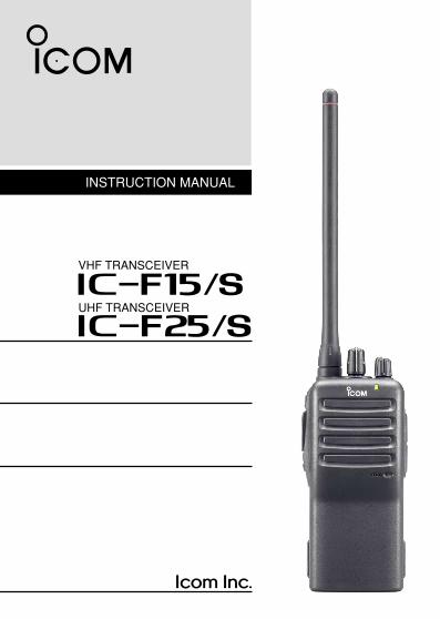
INSTRUCTION MANUAL
UHF TRANSCEIVER
iF25/S
VHF TRANSCEIVER
iF15/S
IC-F15_F25-3.qxd 07.6.29 11:22 AM Page A (1,1)

i
FOREWORDREAD ALL INSTRUCTIONS carefully and completely beforeusing the transceiver.
SAVE THIS INSTRUCTION MANUAL— This instructionmanual contains important operating instructions for the IC-F15/F15S VHF TRANSCEIVER and IC-F25/F25S UHF TRANSCEIVER.
EXPLICIT DEFINITIONS
OPERATING NOTES• When transmitting with a portable radio, hold the radio in a vertical
position with its microphone 5 to 10 centimeters away from yourmouth. Keep the antenna at least 2.5 centimeters from your headand body.
• If you wear a portable two-way radio on your body, ensure that theantenna is at least 2.5 centimeters from your body when transmit-ting.
WORD DEFINITION
RWARNING Personal injury, fire hazard or electric shock may occur.
NOTE If disregarded, inconvenience only. No risk of personal injury, fire or electric shock.
CAUTION Equipment damage may occur.
IC-F15_F25-3.qxd 07.6.29 11:22 AM Page i (1,1)

ii
PRECAUTIONR WARNING! NEVER hold the transceiver so that the antennais very close to, or touching exposed parts of the body, especiallythe face or eyes, while transmitting. The transceiver will performbest if the microphone is 5 to 10 cm away from the lips and thetransceiver is vertical.
R WARNING! NEVER operate the transceiver with a headsetor other audio accessories at high volume levels.
CAUTION! NEVER short the terminals of the battery pack.
NEVER connect the transceiver to a power source other than theBP-230N or BP-232N. Such a connection will ruin the trans-ceiver.
DO NOT push the PTT when not actually desiring to transmit.
AVOID using or placing the transceiver in direct sunlight or inareas with temperatures below –25°C or above +55°C.
DO NOT modify the transceiver for any reason.
MAKE SURE the flexible antenna and battery pack are securelyattached to the transceiver, and that the antenna and battery packare dry before attachment. Exposing the inside of the transceiverto water will result in serious damage to the transceiver.The use of non-Icom battery packs/chargers may impair transceiverperformance and invalidate the warranty.
Icom, Icom Inc. and the logo are registered trademarks of Icom Incorpo-rated (Japan) in the United States, the United Kingdom, Germany, France, Spain,Russia and/or other countries.
IC-F15_F25-3.qxd 07.6.29 11:22 AM Page ii (1,1)

iii
TABLE OF CONTENTSFOREWORD ……………………………………………………………… iEXPLICIT DEFINITIONS ………………………………………………… iOPERATING NOTES ……………………………………………………… iPRECAUTION …………………………………………………………… iiTABLE OF CONTENTS ………………………………………………… iii1 ACCESSORIES ……………………………………………………… 1–5
‘ Supplied accessories………………………………………………… 1‘ Accessory attachments……………………………………………… 2
2 PANEL DESCRIPTION …………………………………………… 6–11‘ Front, top and side panels ………………………………………… 6‘ LED indicator ………………………………………………………… 8‘ Programmable function keys ……………………………………… 9
3 CONVENTIONAL OPERATION ………………………………… 12–17‘ Turning power ON ………………………………………………… 12‘ Channel selection ………………………………………………… 12‘ Call procedure ……………………………………………………… 13‘ Receiving and transmitting ……………………………………… 14‘ Scrambler function ………………………………………………… 16‘ Setting the squelch level ………………………………………… 16‘ Man Down Emergency Call ……………………………………… 17‘ Emergency Call …………………………………………………… 17
4 OPTIONAL UNIT INSTALLATION……………………………… 18–19‘ Optional unit installation …………………………………………… 18‘ Scrambler unit installation ………………………………………… 19
5 BATTERY CHARGING ………………………………………… 20–27‘ Caution ……………………………………………………………… 20‘ Optional battery chargers ………………………………………… 23
6 BATTERY CASE ………………………………………………… 28–29‘ Optional battery case (BP-240) …………………………………… 28
7 SWIVEL BELT CLIP……………………………………………… 30–33‘ MB-93 contents …………………………………………………… 30‘ To attach …………………………………………………………… 30‘ To detach …………………………………………………………… 32
8 OPTIONS ………………………………………………………… 34–379 DOC………………………………………………………………… 38–39
IC-F15_F25-3.qxd 07.6.29 11:22 AM Page iii (1,1)

1
1ACCESSORIES1� Supplied accessories
The following accessories are supplied: Qty.q Flexible antenna . . . . . . . . . . . . . . . . . . . . . . . . . . . . . . . . . . . .1w Battery pack . . . . . . . . . . . . . . . . . . . . . . . . . . . . . . . . . . . . . . .1e Belt clip . . . . . . . . . . . . . . . . . . . . . . . . . . . . . . . . . . . . . . . . . . .1r Unit cover (double-sided tape)* . . . . . . . . . . . . . . . . . . . . . . . .1t Jack cover (with screws) . . . . . . . . . . . . . . . . . . . . . . . . . . .1 set* Use the unit cover as a spare. Ask your dealer for details.
q w
r
e
t
IC-F15_F25-3.qxd 07.6.29 11:22 AM Page 1 (1,1)

2
1 ACCESSORIES
� Accessory attachmentsD Flexible antennaConnect the supplied flexible an-tenna to the antenna connector.
CAUTION:• NEVER HOLD by the antenna
when carrying the transceiver.• Transmitting without an antenna
may damage the transceiver.
IC-F15_F25-3.qxd 07.6.29 11:22 AM Page 2 (1,1)
3
1ACCESSORIES
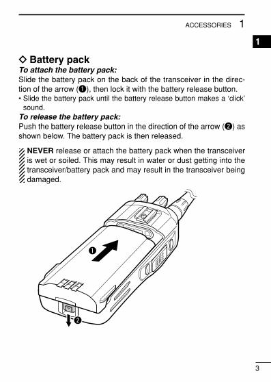
1
ï Battery packTo attach the battery pack:Slide the battery pack on the back of the transceiver in the direc-tion of the arrow (q), then lock it with the battery release button.• Slide the battery pack until the battery release button makes a ‘click’
sound.To release the battery pack:Push the battery release button in the direction of the arrow (w) asshown below. The battery pack is then released.
NEVER release or attach the battery pack when the transceiveris wet or soiled. This may result in water or dust getting into thetransceiver/battery pack and may result in the transceiver beingdamaged.
q
w
IC-F15_F25-3.qxd 07.6.29 11:22 AM Page 3 (1,1)

4
1 ACCESSORIES
ï Jack coverAttach the jack cover when the optional speaker-microphone is notused.
w
w
q
q
q
w
To attach the jack cover:q Attach the jack cover to the
[SP MIC] connector.w Tighten the screws.
To detach the jack cover:q Unscrew the screws with a
phillips screwdriver.w Detach the jack cover for the
speaker-microphone connec-tion.
IC-F15_F25-3.qxd 07.6.29 11:22 AM Page 4 (1,1)

5
1ACCESSORIES
1D Belt clipTo attach the belt clip:q Release the battery pack if it is attached.w Slide the belt clip in the direction of the arrow until the belt clip is
locked and makes a ‘click’ sound.
To detach the belt clip:q Release the battery pack if it is attached.w Pinch the clip (q), and slide the belt clip in the direction of the
arrow (w).
q
w
IC-F15_F25-3.qxd 07.6.29 11:22 AM Page 5 (1,1)

6
2 PANEL DESCRIPTION� Front, top and side panels
q CHANNEL SW/SELECTOR• IC-F15S/F25S: Toggle the channel switch to select the pre-pro-
grammed channel 1 or 2.• IC-F15/F25 : Rotate the channel selector to select the pre-
programmed memory channels.w VOLUME CONTROL [VOL]
Rotate to turn the power ON/OFF and adjust the audio level.
r
q
w
y
u
i
e
Microphone
Speaker
t
IC-F15S/F25S IC-F15/F25
IC-F15_F25-3.qxd 07.6.29 11:22 AM Page 6 (1,1)

7
2PANEL DESCRIPTION
2e LED INDICATOR (p. 8)➥ Lights red while transmitting.➥ Lights green while receiving a signal, or when the squelch is
open.➥ Lights/blinks orange when the matched 2/5-tone code is re-
ceived, according to the pre-programming.r SPEAKER-MICROPHONE CONNECTOR [SP MIC]
Connects the optional speaker-microphone, earphone, etc.
t DEALER-PROGRAMMABLE KEY [Lower]The desired function can be assigned by your dealer. (p. 9)
y PTT SWITCH [PTT]Push and hold to transmit; release to receive.
u DEALER-PROGRAMMABLE KEY [Upper]The desired function can be assigned by your dealer. (p. 9)
i ANTENNA CONNECTORConnects the supplied antenna.
DD Programmable key reference
Upper
Lower
[SP MIC] jack cover
NOTE: Attach the [SP MIC] jack cover when the optional equip-ment is not used. (p. 4)
IC-F15_F25-3.qxd 07.6.29 11:22 AM Page 7 (1,1)

8
2 PANEL DESCRIPTION
‘‘ LED indicatorThe LED indicator indicates several informa-tion as follows;(Ref.; R=Red, G=Green, O=Orange)
R R R R
O O
O O
G G G G
G G
R O R O R O R O R O R O R O R O
G
G G
R
• TX: Turns Red while transmitting a signal.
• RX: Turns Green while receiving a signal.
• Call LED (ON): When receiving a matched 2/5-tone.
• Call LED (Blink): When receiving a matched 2/5-tone.
• Fast/Slow scan: Blinks while Fast/Slow scan is activated.
• Low BATT1: You should charge the battery. (blinks slowly)
• Low BATT2: You must charge the battery. (blinks fast)
• TX low BATT2: Low BATT2 was detected during TX mode.
• CH err: Non-programmed channel is selected.
IC-F15_F25-3.qxd 07.6.29 11:22 AM Page 8 (1,1)

9
2PANEL DESCRIPTION
2
‘‘ Programmable function keysThe following functions can be assigned to [Upper] and [Lower]programmable function keys.Consult your Icom dealer or system operator for details concerningyour transceivers programming.If the programmable function names are bracketed in the followingexplanations, the specific key used to activate the function dependson programming.
SCAN A KEY➥ This key’s operation depends on the Power ON Scan setting.
When the power ON scan function is turned OFF;Push to start and cancel scanning operation. In case of trans-mission during scan, cancels scanning.When the power ON scan function is turned ON;Push to pause scanning. Scanning resumes after passing aspecified time period. In case of transmission during scan,pauses scanning. Scanning resumes after passing a specifiedtime period.
SCAN B KEYPush to start and cancel scanning operation. In case of transmis-sion during scan, pauses scanning. Scanning resumes after pass-ing a specified time period.
PRIORITY CHANNEL KEYS➥ Push to select the Priority A or Priority B channel.➥ Push and hold [Prio A (Rewrite)] to rewrite the Prio A channel.
MR-CH 1/2/3/4 KEYSPush to select a memory channels 1 to 4 directly.
NOTE: The memory channels 3 and 4 are available for IC-F15S/F25S when [MR-CH 3] and [MR-CH 4] keys are assigned.
IC-F15_F25-3.qxd 07.6.29 11:22 AM Page 9 (1,1)
10
2 PANEL DESCRIPTION
MONITOR KEY➥ Mute and release the CTCSS (DTCS) or 2-tone squelch mute.
Open any squelch/deactivate any mute while pushing this key.(LMR operation only)
➥ Activates one of (or two of) the following functions on each chan-nel independently: (PMR operation only)• Push and hold to un-mute the channel (audio is emitted; ‘Audible’
condition).• Push to mute the channel (sets to ‘Inaudible’ only).• Push to un-mute the channel (sets to ‘Audible’ only).• Push after the communication is finished to send a ‘reset code’.
NOTE: The un-mute condition (‘Audible’ condition) may auto-matically return to the mute condition (‘Inaudible‘ condition)after a specified period.
LOCK KEYPush and hold to electronically lock all programmable keys exceptthe following:[Call] (incl. Call A and Call B), [Moni(Audi)] and [Emergency] keys.
OUTPUT POWER SELECTION KEYSelect the transmit output power temporarily or permanently, de-pending on the pre-setting.• Ask your dealer for the output power level for each selection.
TALK AROUND KEY➥ Push to turn the talk around function OFF.➥ Push and hold to turn the talk around function ON.
• The talk around function equalizes the transmit frequency to the re-ceive frequency for transceiver-to-transceiver communication.
WIDE/NARROW KEY➥ Push to select the IF bandwidth to wide.
• The wide passband width can be selected from 25.0 or 20.0 kHzusing the CS-F14 CLONING SOFTWARE (PMR operation only.) Askyour dealer for details.
➥ Push and hold to select the IF bandwidth to narrow.
IC-F15_F25-3.qxd 07.6.29 11:22 AM Page 10 (1,1)

11
2PANEL DESCRIPTION
2
DTMF AUTODIAL KEYPush to transmit the programmed DTMF code.
CALL KEYSPush to transmit a 2/5-tone code.• Call transmission is necessary before you call another station de-
pending on your signalling system.• [Call A] and/or [Call B] keys may be available when your system em-
ploys selective ‘Individual/Group’ calls. Ask your dealer which call isassigned to each key.
EMERGENCY KEYS➥ Push and hold to transmit an emergency call.➥ When [Emergency Single (Silent)] or [Emergency Repeat
(Silent)] is pushed, an emergency call is transmitted without abeep emission.• If you want to cancel the emergency call, push (or push and hold)
the key again before transmitting the call.• The emergency call is transmitted one time only or repeatedly until
receiving a control code depending on the pre-setting.
VOICE SCRAMBLER FUNCTION KEYS➥ Push to turn the voice scrambler function OFF.➥ Push and hold to turn the voice scrambler function ON.
OPT OUT KEYS➥ Push to inactivate the connected output signal level.➥ Push and hold to activate the connected output signal level.
SIREN KEYPush to emit a siren. This function can be used for situations otherthan an emergency alert such as a security alarm for example.
IC-F15_F25-3.qxd 07.6.29 11:22 AM Page 11 (1,1)
12
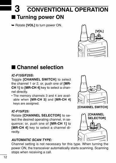
3 CONVENTIONAL OPERATION� Turning power ON➥ Rotate [VOL] to turn power ON.
� Channel selectionIC-F15S/F25S:Toggle [CHANNEL SWITCH] to selectthe channel 1 or 2, or, push one of [MR-CH 1] to [MR-CH 4] key to select a chan-nel directly.• The memory channels 3 and 4 are avail-
able when [MR-CH 3] and [MR-CH 4]keys are assigned.
IC-F15/F25:Rotate [CHANNEL SELECTOR] to se-lect the desired operating channel, in se-quence; or, push one of [MR-CH 1] to[MR-CH 4] key to select a channel di-rectly.
AUTOMATIC SCAN TYPE:Channel setting is not necessary for this type. When turning thepower ON, the transceiver automatically starts scanning. Scanningstops when receiving a call.
[VOL]
[CHANNEL SELECTOR]
[CHANNEL SWITCH]
IC-F15_F25-3.qxd 07.6.29 11:22 AM Page 12 (1,1)

13
3CONVENTIONAL OPERATION
3
� Call procedureWhen your system employs tone signalling (excluding CTCSS andDTCS), the call procedure may be necessary prior to voice trans-mission. The tone signalling employed may be a selective callingsystem which allows you to call specific station(s) only and preventunwanted stations from contacting you.
q Select the desired TX code channel or 2/5-tone code accordingto your System Operator’s instructions.• This may not be necessary depending on programming.
w Push the call key (assigned to one of the dealer programmablekeys.) (p. 11)
e After transmitting a 2/5-tone code, the remainder of your com-munication can be carried out in the normal fashion.
Selective calling Non-selective calling
IC-F15_F25-3.qxd 07.6.29 11:22 AM Page 13 (1,1)

14
3 CONVENTIONAL OPERATION
� Receiving and transmittingNOTE: Transmitting without an antenna may damage the trans-ceiver. See p. 2 for antenna attachment.
Receiving:q Rotate [VOL] to turn power ON.w Toggle [CHANNEL SWITCH] (IC-F15S/F25S), rotate [CHAN-
NEL SELECTOR] (IC-F15/F25) or push one of [MR-CH 1] to[MR-CH 4] key to select a channel.
For IC-F15S/F25S:The memory channels 3 and 4 are available when [MR-CH 3]and [MR-CH 4] keys are assigned.
e When receiving a call, adjust the audio output level to a comfort-able listening level.
Transmitting:Wait for the channel to become clear to avoid interference.q While pushing and holding [PTT], speak into the microphone at
a normal voice level.• When a tone signalling system is used, the call procedure de-
scribed on p. 13 may be necessary.w Release [PTT] to return to receive.
IMPORTANT!: To maximize the readability of your signal;1. Pause briefly after pushing [PTT].2. Hold the microphone 5 to 10 cm from your mouth, then speak
into the microphone at a normal voice level.
IC-F15_F25-3.qxd 07.6.29 11:22 AM Page 14 (1,1)

15
3CONVENTIONAL OPERATION
3D Transmitting notes• Transmit inhibit functionThe transceiver has several inhibit functions which restrict trans-mission under the following conditions:
- The channel is in mute condition.- Channel is busy.- Un-matched (or matched) CTCSS is received.- The selected channel is a ‘receive only’ channel.
• Time-out timerAfter continuous transmission for the pre-programmed time period,the time-out timer activates, and causes the transceiver to stoptransmitting.• Penalty timerOnce the time-out timer activates, transmission is further inhibitedfor a period determined by the penalty timer.• PTTID callThe transceiver sends the ID code (5-tone, DTMF or digital ANI)automatically when [PTT] is pushed (beginning of transmission)and released (end of transmission) depends on the setting.
D DTMF transmissionIf the transceiver has [DTMF Autodial] assigned to it, the automaticDTMF transmission function is available.
➥ Push [DTMF Autodial] to transmit the DTMF code.
IC-F15_F25-3.qxd 07.6.29 11:22 AM Page 15 (1,1)

16
3 CONVENTIONAL OPERATION
� Scrambler functionThe optional voice scrambler units UT-109 (#01) and UT-110 (#01)provide high performance private communication between stationswith the same scrambler codes.
➥ Push and hold [Scrambler] to turn the scrambler function ON.➥ Push [Scrambler] to turn the scrambler function OFF.
� Setting the squelch levelThe squelch circuit mutes the received audio signal depending onthe signal strength.
q While pushing [PTT] and [Lower],rotate [VOL] to turn the power ONto enter the squelch level adjust-ment mode.
w Push [Upper] to increase thesquelch level (tight squelch) or[Lower] to decrease the squelchlevel (loose squelch).
e Rotate [VOL] to turn the powerOFF to fix the squelch level.
[VOL]
[Upper]
[Lower]
[PTT]
IC-F15_F25-3.qxd 07.6.29 11:22 AM Page 16 (1,1)

17
3CONVENTIONAL OPERATION
3
� Man Down Emergency CallThe man down emergency call function transmits an emergencycall automatically, after the transceiver laying down in a horizontalposition for a pre-set time period. (The optional UT-113 MAN DOWN
UNIT is required.)
After the emergency call, the transceiver performs transmission andreception alternately with the following conditions:
- Transmits the microphone signals.- Receives the signal and emits audio.
When the emergency cancel code is received, the function is can-celled.
IMPORTANT!: Set an emergency channel individually, to providecertain emergency call operation is recommended.
� Emergency CallThe emergency call can be performed using the [Emergency Sin-gle] or [Emergency Repeat] key (p. 11). The transceiver will sendan 5-tone, DTMF or MDC 1200 emergency command one time onlyor repeatedly until receiving the control code.The emergency call can be transmitted without a beep emissionand LCD indication change when the [Emergency Single (Silent)]or [Emergency Repeat (Silent)] (p. 11) key is pushed.The emergency transmission is performed on the emergency chan-nel, however, when no emergency channel is specified, the signal istransmitted on the previously selected channel.Ask your dealer for details.
IC-F15_F25-3.qxd 07.6.29 11:22 AM Page 17 (1,1)
18
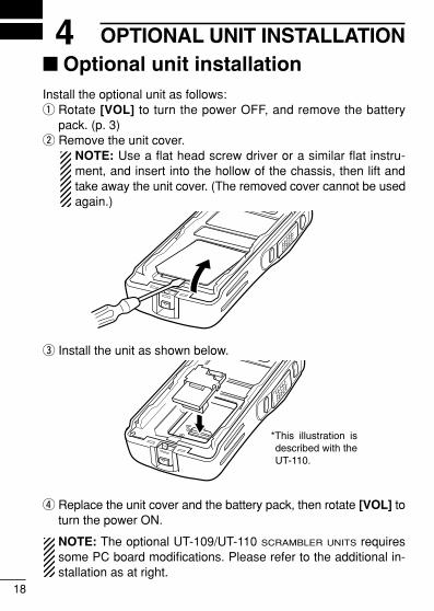
4 OPTIONAL UNIT INSTALLATION� Optional unit installationInstall the optional unit as follows:q Rotate [VOL] to turn the power OFF, and remove the battery
pack. (p. 3)w Remove the unit cover.
NOTE: Use a flat head screw driver or a similar flat instru-ment, and insert into the hollow of the chassis, then lift andtake away the unit cover. (The removed cover cannot be usedagain.)
e Install the unit as shown below.
r Replace the unit cover and the battery pack, then rotate [VOL] toturn the power ON.
NOTE: The optional UT-109/UT-110 SCRAMBLER UNITS requiressome PC board modifications. Please refer to the additional in-stallation as at right.
*This illustration is described with the UT-110.
IC-F15_F25-3.qxd 07.6.29 11:22 AM Page 18 (1,1)
19
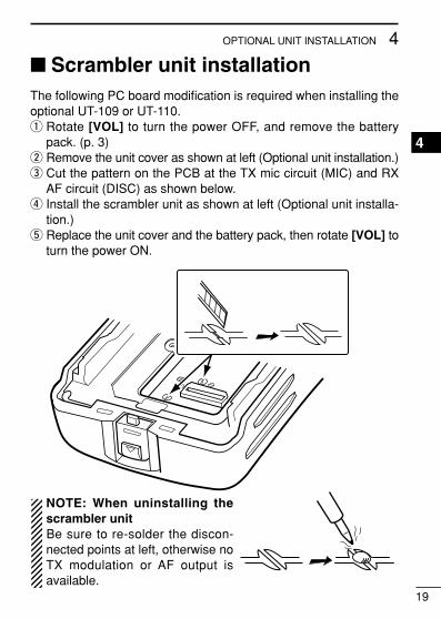
4OPTIONAL UNIT INSTALLATION
4
� Scrambler unit installationThe following PC board modification is required when installing theoptional UT-109 or UT-110.q Rotate [VOL] to turn the power OFF, and remove the battery
pack. (p. 3)w Remove the unit cover as shown at left (Optional unit installation.)e Cut the pattern on the PCB at the TX mic circuit (MIC) and RX
AF circuit (DISC) as shown below.r Install the scrambler unit as shown at left (Optional unit installa-
tion.)t Replace the unit cover and the battery pack, then rotate [VOL] to
turn the power ON.
NOTE: When uninstalling thescrambler unitBe sure to re-solder the discon-nected points at left, otherwise noTX modulation or AF output isavailable.
IC-F15_F25-3.qxd 07.6.29 11:22 AM Page 19 (1,1)
20
5 BATTERY CHARGING� Caution
R DANGER! Use and charge only specified Icom battery packswith Icom radios or Icom charger. Only Icom battery packs aretested and approved for use and charge with Icom radios or Icomcharger. Using third-party or counterfeit battery packs or chargermay cause smoke, fire, or cause the battery to burst.
DD Battery cautionR DANGER! DO NOT hammer or otherwise impact the battery. Donot use the battery if it has been severely impacted or dropped, or ifthe battery has been subjected to heavy pressure. Battery damagemay not be visible on the outside of the case. Even if the surface ofthe battery does not show cracks or any other damage, the cells in-side the battery may rupture or catch fire.
R DANGER! NEVER use or leave battery packs in areas with tem-peratures above +60˚C. High temperature buildup in the battery,such as could occur near fires or stoves, inside a sun heated car, orin direct sunlight may cause the battery to rupture or catch fire. Ex-cessive temperatures may also degrade battery performance orshorten battery life.
R DANGER! DO NOT expose the battery to rain, snow, seawater,or any other liquids. Do not charge or use a wet battery. If the bat-tery gets wet, be sure to wipe it dry before using. The battery is notwaterproof.
R DANGER! NEVER incinerate used battery packs since internalbattery gas may cause them to rupture, or may cause an explosion.
Misuse of Lithium-ion batteries may result in the followinghazards: smoke, fire, or the battery may rupture. Misuse canalso cause damage to the battery or degradation of batteryperformance.
IC-F15_F25-3.qxd 07.6.29 11:22 AM Page 20 (1,1)
21
5BATTERY CHARGING
R DANGER! NEVER solder the battery terminals or NEVER mod-ify the battery pack. This may cause heat generation, and the bat-tery may rupture, emit smoke or catch fire.
R DANGER! Use the battery only with the transceiver for which itis specified. Never use a battery with any other equipment, or forany purpose that is not specified in this instruction manual.
R DANGER! If fluid from inside the battery gets in your eyes, blind-ness can result. Rinse your eyes with clean water, without rubbingthem, and see a doctor immediately.
WARNING! Immediately stop using the battery if it emits an abnor-mal odor, heats up, or is discolored or deformed. If any of theseconditions occur, contact your Icom dealer or distributor.
WARNING! Immediately wash, using clean water, any part of thebody that comes into contact with fluid from inside the battery.
WARNING! NEVER put the battery in a microwave oven, high-pressure container, or in an induction heating cooker. This couldcause a fire, overheating, or cause the battery to rupture.
CAUTION! Always use the battery within the specified temperaturerange for the transceiver (–25˚C to +55˚C) and the battery itself(–20˚C to +60˚C). Using the battery out of its specified temperaturerange will reduce the battery’s performance and battery life. Pleasenote that the specified temperature range of the battery may ex-ceed that of the transceiver. In such cases, the transceiver may notwork properly because it is out of its operating temperature range.
CAUTION! Shorter battery life could occur if the battery is left fullycharged, completely discharged, or in an excessive temperatureenvironment (above +50˚C) for an extended period of time. If thebattery must be left unused for a long time, it must be detachedfrom the radio after discharging. You may use the battery until theremaining capacity is about half, then keep it safely in a cool dryplace with the temperature between –20˚C to +20˚C.
1
2
3
4
5
6
7
8
9
10
11
12
13
14
15
16
17
18
19
20
IC-F15_F25-3.qxd 07.6.29 11:22 AM Page 21 (1,1)

22
5 BATTERY CHARGING
DD Charging cautionR DANGER! NEVER charge the battery pack in areas with ex-tremely high temperatures, such as near fires or stoves, inside asun heated car, or in direct sunlight. In such environments, thesafety/protection circuit in the battery will activate, causing the bat-tery to stop charging.
WARNING! DO NOT charge or leave the battery in the batterycharger beyond the specified time for charging. If the battery is notcompletely charged by the specified time, stop charging and re-move the battery from the battery charger. Continuing to charge thebattery beyond the specified time limit may cause a fire, overheat-ing, or the battery may rupture.
WARNING! NEVER insert the transceiver (battery attached to thetransceiver) into the charger if it is wet or soiled. This could corrodethe battery charger terminals or damage the charger. The charger isnot waterproof.
CAUTION! DO NOT charge the battery outside of the specifiedtemperature range: BC-160 and BC-171 (0˚C to +40˚C). Icom rec-ommends charging the battery at +20˚C. The battery may heat upor rupture if charged out of the specified temperature range. Addi-tionally, battery performance or battery life may be reduced.
IC-F15_F25-3.qxd 07.6.29 11:22 AM Page 22 (1,1)

23
5BATTERY CHARGING
� Optional battery chargersD Rapid charging with the BC-160The optional BC-160 provides rapid charging of the Li-Ion batterypack. Charging period: Approx. 3 hours (with BP-232N)
The following items are additionally required:• An AC adapter (may be supplied depending on version) or the DC
power cable (OPC-515L/CP-17L) is additionally required.
AC adapter(Not supplied with some versions.)
Optional OPC-515L (for 13.8 V power source) or CP-17L (for 12 V cigarette lighter socket) can be used instead of the AC adapter.
Battery packTransceiver
Turn power OFF
bc-160
IMPORTANT!:Ensure the guide lobs on the battery pack are correctly aligned with the guide rails inside the charger adapter.
Guide rail
Lobs
1
2
3
4
5
6
7
8
9
10
11
12
13
14
15
16
17
18
19
20
IC-F15_F25-3.qxd 07.6.29 11:22 AM Page 23 (1,1)
24
5 BATTERY CHARGING
D Regular charging with the BC-171The optional BC-171 provides regular charging of the Li-Ion batterypack. Charging period: Approx. 10 hours (with BP-232N)
The following items are additionally required:• An AC adapter (may be supplied depending on version) or the DC
power cable (OPC-515L/CP-17L) is additionally required.
AC adapter(Not supplied with some versions.)
Optional OPC-515L (for 13.8 V power source) or CP-17L (for 12 V cigarette lighter socket) can be used instead of the AC adapter.
Battery packTransceiver
Turn power OFF
IMPORTANT!:Ensure the guide lobs on the battery pack are correctly aligned with the guide rails inside the charger adapter.
Guide rail
Lobs
IC-F15_F25-3.qxd 07.6.29 11:22 AM Page 24 (1,1)
25
5BATTERY CHARGING
ï AD-106 installationThe AD-106 CHARGER ADAPTER must be installed into the BC-119Nor BC-121N before battery charging.
➥ Connect the AD-106 CHARGER ADAPTER and the BC-119N/BC-121N as below, then install the AD-106 into the holder space ofthe BC-119N or BC-121N with the supplied screws.
Screws supplied with the charger adapter
AD-106
Connectors
Plugs
1
2
3
4
5
6
7
8
9
10
11
12
13
14
15
16
17
18
19
20
IC-F15_F25-3.qxd 07.6.29 11:22 AM Page 25 (1,1)

26
5 BATTERY CHARGING
D Rapid charging with the BC-119N+AD-106The optional BC-119N provides rapid charging of the Li-Ion batterypack. Charging period: Approx. 3 hours (with BP-232N)
The following items are additionally required:• An AD-106 CHARGER ADAPTER
• An AC adapter (may be supplied with BC-119N depending on version)or the DC power cable (OPC-515L/CP-17L).
AD-106 charger adapter is instal-led in BC-119N.
AC adapter(Not supplied with some versions.)
Optional OPC-515L (for 13.8 V power source) or CP-17L (for 12 V cigarette lighter socket) can be used instead of the AC adapter.
Battery pack
TransceiverTurn power OFF
IMPORTANT!:Ensure the guide lobs on the battery pack are correctly aligned with the guide rails inside the charger adapter.
Lobs
Guide rails
IC-F15_F25-3.qxd 07.6.29 11:22 AM Page 26 (1,1)

27
5BATTERY CHARGING
1
2
3
4
5
6
7
8
9
10
11
12
13
14
15
16
17
18
19
20
D Rapid charging with the BC-121N+AD-106The optional BC-121N allows up to 6 battery packs to be chargedsimultaneously. Charging period: Approx. 3 hours (with BP-232N)
The following items are additionally required.• Six AD-106 CHARGER ADAPTER
• An AC adapter (BC-157) or the DC power cable (OPC-656)
AC adapter(Purchased separately)
AD-106 charger adapters are installed in each slot.
DC power cable(OPC-656)(Connect with the DC power supply; 13.8 V/at least 7 A)
Battery pack
TransceiverTurn power OFF
IMPORTANT!:Ensure the guide lobs on the bat-tery pack are correctly aligned with the guide rails inside the charger adapter.
Guide rails
Lobs
IC-F15_F25-3.qxd 07.6.29 11:22 AM Page 27 (1,1)

28
6 BATTERY CASE� Optional battery case (BP-240)When using the optional battery case, install 6 × AAA (LR03) sizealkaline batteries as illustrated at right.
q Unhook the battery cover release hook (q), and open the coverin the direction of the arrow (w). (Fig.1)
w Then, install 6 × AAA (LR03) size alkaline batteries. (Fig.2)• Install the alkaline batteries only.• Be sure to observe the correct polarity.• Do not pin the ribbon under the batteries.
e Fit the cover in the direction of the arrow (e), then close (r).Hook the battery cover release hook until it makes a ‘click’ sound(t). (Fig.3)
CAUTION:• When installing batteries, make sure they are all the same
brand, type and capacity. Also, do not mix new and old batter-ies together.
• Keep battery contacts clean. It’s a good idea to clean batteryterminals once a week.
• Never incinerate used battery cells since internal battery gasmay cause them to rupture.
• Never expose a detached battery case to water. If the batterycase gets wet, be sure to wipe it dry before using it.
NOTE: When the optional battery case is attached, the batterytype must be selected to “Alkaline battery operation” when turn-ing the transceiver ON. Ask your dealer for details.
IC-F15_F25-3.qxd 07.6.29 11:22 AM Page 28 (1,1)

29
6BATTERY CASE
1
2
3
4
5
6
7
8
9
10
11
12
13
14
15
16
17
18
19
20
q
BP-240wFig.1
Fig.2
Fig.3e
r
t
IC-F15_F25-3.qxd 07.6.29 11:22 AM Page 29 (1,1)

30
7 SWIVEL BELT CLIP� MB-93 contents
Qty.q Belt clip …………………………………………………………… 1w Base clip …………………………………………………………… 1
� To attachq Release the battery pack if it is attached. (p. 3)w Slide the base clip in the direction of the arrow until the base clip
is locked and makes a ‘click’ sound.
q w
IC-F15_F25-3.qxd 07.6.29 11:22 AM Page 30 (1,1)

31
7SWIVEL BELT CLIP
e Clip the belt clip to a part of your belt. And insert the transceiverinto the belt clip until the base clip inserted fully into the groove.
r Once the transceiver is locked in place, it swivels as illustratedbelow.
1
2
3
4
5
6
7
8
9
10
11
12
13
14
15
16
17
18
19
20
IC-F15_F25-3.qxd 07.6.29 11:22 AM Page 31 (1,1)

32
7 SWIVEL BELT CLIP
� To detachq Turn the transceiver upside down in the direction of the arrow
and pull out from the belt clip.
IC-F15_F25-3.qxd 07.6.29 11:22 AM Page 32 (1,1)

33
7SWIVEL BELT CLIP
w Release the battery pack if it is attached. (p. 3)e Pinch the clip (q), and slide the base clip in the direction of the
arrow (w).
CAUTION:HOLD THE TRANSCEIVER TIGHTLY, WHEN HANGING ORDETACHING THE TRANSCEIVER FROM THE BELT CLIP.Otherwise the transceiver may not be attached to the holder orswivel properly if the transceiver is accidentally dropped and thebase clip is scratched or damaged.
qw
1
2
3
4
5
6
7
8
9
10
11
12
13
14
15
16
17
18
19
20
IC-F15_F25-3.qxd 07.6.29 11:22 AM Page 33 (1,1)

34
8 OPTIONSD BATTERY PACK
D CHARGERS• BC-119N DESKTOP CHARGER + AD-106 CHARGER ADAPTER
+ BC-145 AC ADAPTER
For rapid charging of battery packs. An AC adapter is suppliedwith the charger depending on versions. Charging time: approx. 3hours when BP-232N is attached.
• BC-121N MULTI-CHARGER + AD-106 CHARGER ADAPTER (6 pcs.)+ BC-157 AC ADAPTER
For rapid charging of up to 6 battery packs (six AD-106’s are re-quired) simultaneously. An AC adapter should be purchased sepa-rately. Charging time: approx. 3 hours when BP-232N is attached.
• BC-160 DESKTOP CHARGER + BC-145 AC ADAPTER
For rapid charging of battery packs. An AC adapter is suppliedwith the charger depending on versions. Charging time: approx. 3hours when BP-232N is attached.
• BC-171 DESKTOP CHARGER + BC-147 AC ADAPTER
For regular charging of battery packs. We recommend that theBP-230N charging. An AC adapter is supplied with the charger de-pending on versions.Charging time: Approx. 10 hours when BP-232N is attached.
Approx. 4 hours when BP-230N is attached.
7.4 V
7.4 V
9 hrs.
18 hrs.
980 mAh
2000 mAh
Battery pack
BP-230N
BP-232N
Voltage Capacity Battery life*1
*1 When the power save function is turned ON, and the operating periods are calculated under the following conditions;
TX : RX : standby = 5 : 5 : 90
Battery case for AAA(LR03) × 6 alkalineBP-240
*2 Operating period depends on the alkaline cells used.
—*2
IC-F15_F25-3.qxd 07.6.29 11:22 AM Page 34 (1,1)

35
8OPTIONS
D OPTIONAL UNITS• UT-108 DTMF DECODER UNIT
Provides pager and code squelch capabilities.• UT-109 (#01)/UT-110 (#01) SCRAMBLER UNITS
Non-rolling type (UT-109)/Rolling type (UT-110) voice scramblerunit provides higher communication security.
• UT-124 MAN DOWN UNIT
Provides a measure of safety when working in a hazardous envi-ronment, etc.
D BELT CLIPS• MB-93 SWIVEL BELT CLIP
• MB-94 BELT CLIP
Exclusive alligator-type belt clip. The same as supplied with thetransceiver.
• MB-96N/96F LEATHER BELT HANGER
D DC CABLES• CP-17L CIGARETTE LIGHTER CABLE
Allows charging of the battery pack through a 12 V cigarettelighter socket. (For BC-119N)
• OPC-515L/OPC-656 DC POWER CABLES
Allows charging of the battery pack using a 13.8 V power sourceinstead of the AC adapter.OPC-515L: For BC-119NOPC-656 : For BC-121N
D OTHER OPTIONS• SP-13 EARPHONE
Provides clear receive audio in noisy environment.• HM-153L EARPHONE-MICROPHONE
• HM-131L/158L/159L SPEAKER-MICROPHONE
Combination speaker-microphone that provides convenient oper-ation while hanging the transceiver from your belt.
1
2
3
4
5
6
7
8
9
10
11
12
13
14
15
16
17
18
19
20
IC-F15_F25-3.qxd 07.6.29 11:22 AM Page 35 (1,1)
36
8 OPTIONS
• HS-94/HS-95/HS-97 HEADSET + VS-1L VOX/PTT CASE
HS-94: Ear hook type HS-95: Neck-arm typeHS-97: Throat microphoneVS-1L: VOX/PTT switch box for hands-free operation, etc.
• FA-SC73US/FA-SC56VS/FA-SC57VS STUBBY ANTENNAS
FA-SC73US: 450–490 MHz FA-SC56VS: 150–162 MHzFA-SC57VS: 160–174 MHz
• FA-SC01U/FA-SC25U/FA-SC57U/FA-SC72U/FA-SC25V/FA-SC55V ANTENNAS
FA-SC01U: 350–400 MHz FA-SC25U: 400–430 MHzFA-SC57U: 430–470 MHz FA-SC72U: 470–520 MHzFA-SC25V: 136–155 MHz FA-SC55V: 146–174 MHz
• FA-SC61VC/FA-SC61UC CUT ANTENNAS
FA-SC61VC: 136–174 MHz FA-SC61UC: 380–520 MHz
Some options may not be available in some countries. Please ask yourdealer for details.
IC-F15_F25-3.qxd 07.6.29 11:22 AM Page 36 (1,1)

37
8OPTIONS
1
2
3
4
5
6
7
8
9
10
11
12
13
14
15
16
17
18
19
20
ï About VS-1L VOX/PTT CASEThe VS-1L is a VOX/PTT unit for Icom handheld transceivers, andallows you hands-free operation.An optional headset (HS-94, etc.) is additionally required for opera-tion.• The VOX (voice operated transmission) function starts transmission
without pushing PTT switch when you speak into the microphone;then, automatically returns to receive when you stop speaking.
Features➥ Straight type head SP/MIC plug equipped➥ Water resistant construction➥ Durable construction➥ Equipped with a PTT switch and revolving clip.
MIC/VOX gain adjustment1 Remove the water protection cover on the right side of the VS-1L.2 Adjust the MIC/VOX gain with a thin screw driver. Clockwise ro-
tation increases the MIC/VOX gain.3 Return the protective cover back to the MIC/VOX gain adjustment
hole.
VS-1L
VOX
PTT
Adjusting pot
Water protection cover
PTT switch
IC-F15_F25-3.qxd 07.6.29 11:22 AM Page 37 (1,1)

38
9 DOCCE versions of the IC-F15/S and IC-F25/S whichdisplay the “CE” symbol on the serial number seal,comply with the essential requirements of the Euro-pean Radio and Telecommunication Terminal Direc-tive 1999/5/EC.
DECLARATIONOF CONFORMITY
We Icom Inc. Japan1-1-32, Kamiminami, Hirano-kuOsaka 547-0003, Japan
Kind of equipment: VHF TRANSCEIVER
Type-designation: iC- f15/s
Signature
Authorized representative name
Place and date of issue
Düsseldorf 30th June 2004
Declare on our sole responsibility that this equipment complies with theessential requirements of the Radio and Telecommunications Terminal Equipment Directive, 1999/5/EC, and that any applicable Essential TestSuite measurements have been performed.
Version (where applicable):
0168
136 174 MHz 12.5 kHz/20 kHz/25 kHz
This compliance is based on conformity with the following harmonised standards, specifications or documents:i) EN 301 489-1 v1.3.1 (Sept 2001)ii) EN 301 489-5 (August 2000)iii) EN 60950 (August 1992+A11) iv) EN 300 086-2 (March 2001) v) EN 300 219-2 (March 2001)vi) EN 300 113-2 (March 2001)
IC-F15_F25-3.qxd 07.6.29 11:22 AM Page 38 (1,1)

39
9DOC
This warning symbol indicates that this equipment op-erates in non-harmonised frequency bands and/or maybe subject to licensing conditions in the country of use.Be sure to check that you have the correct version ofthis radio or the correct programming of this radio, tocomply with national licensing requirement.
DECLARATIONOF CONFORMITY
We Icom Inc. Japan1-1-32, Kamiminami, Hirano-kuOsaka 547-0003, Japan
Kind of equipment: UHF TRANSCEIVER
Type-designation: iC- f25/s
Signature
Authorized representative name
Place and date of issue
Düsseldorf 30th July 2004
Declare on our sole responsibility that this equipment complies with theessential requirements of the Radio and Telecommunications Terminal Equipment Directive, 1999/5/EC, and that any applicable Essential TestSuite measurements have been performed.
Version (where applicable):
0168
400–470 MHz 12.5 kHz/20 kHz/25 kHz
This compliance is based on conformity with the following harmonised standards, specifications or documents:i) EN 301 489-1 v1.3.1 (Sept 2001)ii) EN 301 489-5 (August 2000)iii) EN 60950 (August 1992+A11) iv) EN 300 086-2 (March 2001) v) EN 300 219-2 (March 2001)vi) EN 300 113-2 (March 2001)
1
2
3
4
5
6
7
8
9
10
11
12
13
14
15
16
17
18
19
20
IC-F15_F25-3.qxd 07.6.29 11:22 AM Page 39 (1,1)

MEMO
IC-F15_F25-3.qxd 07.6.29 11:22 AM Page 40 (1,1)

MEMO
IC-F15_F25-3.qxd 07.6.29 11:22 AM Page 41 (1,1)

MEMO
IC-F15_F25-3.qxd 07.6.29 11:22 AM Page 42 (1,1)

MEMO
IC-F15_F25-3.qxd 07.6.29 11:22 AM Page 43 (1,1)

1-1-32 Kamiminami, Hirano-ku, Osaka 547-0003, Japan
< Intended Country of Use > GER AUT GBR IRL NOR
FRA NED BEL LUX
ESP POR ITA GRE
SWE DEN FIN SUI
A-6370D-1EU-ePrinted in Japan© 2004–2007 Icom Inc.
Printed on recycled paper with soy ink.
IC-F15_F25-3.qxd 07.6.29 11:22 AM Page 44 (1,1)