uiuc big idea presenation
TRANSCRIPT

Cable-Controlled Aeroshell Deceleration System
Sashank Gummella, Sophomore, Aerospace EngineeringSteven Kosvick, Sophomore, Aerospace EngineeringAustin Scott, Sophomore, Aerospace EngineeringJose Tuason, Graduate Student, Aerospace EngineeringSamuel Wywrot, Sophomore, Aerospace Engineering
Faculty Advisor:Dr. Zachary Putnam, Aerospace Engineering
1

The Challenge• A vehicle capable of carrying 15-30 tonnes is necessary in
order to land on and return humans safely from Mars– Beyond the limits of 1960s-1970s technology
• Newly developed HIAD technology has great potential due to its efficient storage
• HIAD vehicles can mitigate deceleration forces on crew, loft and extend EDL events, and enable precision landing via generation of lift
2
Big Idea Challenge hosted by the NIA

CCADS - Design OverviewThe Cable Controlled Aerodynamic Decelerator System (CCADS) undergoes aeroshell shape morphing via tension applied through cables (fine control) and CG offsetting (coarse control) to control its lift vector.
• Key components:– HIAD aeroshell – Cables– Electric Motor
3
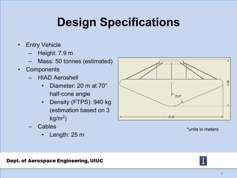
Design Specifications• Entry Vehicle
– Height: 7.9 m– Mass: 50 tonnes (estimated)
• Components– HIAD Aeroshell
• Diameter: 20 m at 70° half-cone angle
• Density (FTPS): 940 kg (estimation based on 3 kg/m2)
– Cables• Length: 25 m
4
*units in meters

Cables• Temperature range 350°C-450°C• Material
– Carbon-based composite (CFCC, C-C) – Graphite fiber-phthalonitrile– Thermal resistant
• Gutters/Sleeves– Protect and guide cables during morphing– Made of heat resistant and low-friction material
• Three Torus Interface Configurations
5

Torus Configuration Options
6
Valley Cable Arrangement reduces protrusion of sleeves/gutters
Segmented Toroidal Arrangement decreases likelihood of buckling while also helping to prevent protrusions
Strap-Stitch Arrangement reduces protrusions of cable system and more evenly distributes tension load on torus

Electric Motor • One electric motor housing on top of upper section of
payload compartment– Applies tension to cables to morph the aeroshell– Increases maneuverability
• BLDC motors must be tailored to mission concept• Structural analysis and testing of aeroshell loads
– Effect of tensile forces on shape-morphing – Power and mass of BLDC motor per cable
7

Mission Profile• Deployment and configuration
– Aeroshell inflation occurs prior to atmospheric entry
– Nominal aeroshell configuration is defined by a 70° half-cone angle
• Point 1: 70 km, initialize control• Point 2: 50 km, start of vehicle loft• Point 3: 70 km, suspension of
control to conserve energy • Point 4: 70 km, re-initialize control• Point 5: 11 km, terminal descent
phase
8
1
2
34
5

Control• Coarse control → CG shifting
– Large adjustments to L/D• Fine control → cable-controlled
aeroshell morphing– Small adjustments to L/D
• Even small changes in L/D yield noticeable changes in range
9
Above Images credited to Justin Green

Downrange and Crossrange Control• Test conditions
– Velocity: 5800 m/s– Flight Path Angle: -10°– Ballistic Coefficient: 99 kg/m2
– Bank angle:• 0° for downrange simulation• 45° bank angle for crossrange simulation
• Downrange Δkm of 800 km between 0.05 to 0.25 L/D at 0° bank angle
– Δkm of 590 km between 0.25 to 0.30 L/D• Crossrange Δkm of 35 km over same L/D at 45° bank
angle– Δkm 33 km between 0.25 to 0.30 L/D– Substantial reduction in downrange capability with
banks greater than 25°• Fine tuning via Shape Morphing allows for increased
landing accuracy
10

Heating and G-forces• Baseline entry initial conditions:
- Velocity: 5800 m/s- Flight Path Angle: -11゜- L/D: 0.24- Bank Angle: 0゜- Ballistic Coefficient: 99 kg/m2
• Entry vehicle experiences a maximum of 3.9 G’s at baseline conditions– NASA’s limit for sustained G-forces on crew
is 4 G’s• Maximum heat flux is approximately 40 W/cm2
– 2nd Generation FTPS materials such as Nicalon SiC can withstand up to 50 W/cm2
• Integrated heat loading is 4640 J/cm2
– Average heat flux of 6 W/cm2
– Duration is 800 s
11

Testing and Future Development • Test alternative cable types, materials, configurations• Limitations of shape morphing
– Buckling and creasing detection– FTPS wrinkling– Aeroshell inflation pressure
• Mission Concepts– Crewed and uncrewed mission potential– Low-altitude geographic surveyance – Ionospheric and weather pattern observation– Recyclable parts (explorers could reuse motors/cables)
12

Summary
• CCADS is able to deliver 25 or higher tonne payloads to Mars using HIAD technology
• Scalable and relatively lightweight system• Provides coarse and fine L/D shifting in order to accurately
change and refine course• Is able to loft and extend EDL time frame to reduce
deceleration forces and heat flux • Potential to be cheaper than pre-existing technology and
alternatives
13

Acknowledgements• Judges
– Neil Cheatwood– Anthony Calomino– Michelle Munk– Dick Powell– Steve Sandford– Mary Beth Wusk
• NIA – Stacy Dees– Carolyn Sager
• NASA Langley Research Center
14