ult-2000 series product overview - bcgroupintl.combcgroupintl.com/bc_biomedical_manuals/pdf/ult-2000...
TRANSCRIPT

1
BC Group International Inc.
3081 Elm Point Industrial Dr.
St. Charles, MO 63301
1-314-638-3800
1-800-242-8428
Fax 1-314-638-3200
www.bcgroupintl.com
ULT-2000 Series Product Overview
Are your TEE and other types of “invasive” ultrasound transducers safe?
Or are you putting your patients needlessly at risk?
Sonosite TEE Transducer Courtesy of Sonosite, Inc.
Bothell, WA
www.sonosite.com

2
INDEX The Next Generation in TEE Transducer Testing is Here........................................................... 3
Why Should You Test Your Transducers Anyway? .................................................................... 3
How Can Ultrasound Transducers Be Easily Tested? ................................................................ 8
Can Non-Technically Oriented Personnel Perform These Tests? .............................................. 9
Can Technically-Oriented Personnel Get Important Measurement Data? .................................. 9
Competitive Product Comparison ............................................................................................. 11
The Difference Starts with the Bath Conductivity Test .............................................................. 11
Dealing With Real World Parameters ....................................................................................... 13
Why Test With AC Voltages Instead of DC Voltages? .............................................................. 13
Can Test Results Be Archived for Legal Liability Purposes? .................................................... 14
PC Utility Software Makes It Easy ............................................................................................ 14
Ultrasound Transducer Adapter Compatibility .......................................................................... 14
Available Transducer Adapters ................................................................................................. 15
Advanced Features for Advanced Users .................................................................................. 15
Competitive Product Cost Comparison ..................................................................................... 15
Conclusion ................................................................................................................................ 16
ULT-2000 Series Product Specifications .................................................................................. 17
Technical References ............................................................................................................... 19
APPENDICES APPENDIX A (Siemens DALE 800A Instrument Specifications) .............................................. 21
APPENDIX B (Fluke Biomedical ULT-800 Instrument Specifications) ...................................... 22
APPENDIX C (Dale Technology DALE800 Instrument Specifications) .................................... 23
APPENDIX D (Sonosite TEE Electrical Safety Test Description) ............................................. 24
APPENDIX E (Sonosite TEE Bite Hole Inspection Test – 1st page) ......................................... 25
APPENDIX F (Sonosite TEE Bite-Hole Inspection Test – 2nd page) ......................................... 26
APPENDIX G (GE Healthcare Simplified Leakage Current Setup) .......................................... 27
APPENDIX H (Voltaic Cells) ..................................................................................................... 28
APPENDIX I (Sample Printout of Test Results form ULT-2000) ............................................... 29
APPENDIX J (History of BC Group International, Inc.) ............................................................. 30
NOTICE: BC Group, BC Biomedical, and ULT-2000 are
trademarks of BC Group International, Inc. All other
trademarks are property of their respective owners.

3
The Next Generation in TEE Transducer Testing is Here
Until now, commercially available dedicated electrical leakage current testing systems for TEE and other types of “invasive” diagnostic ultrasound transducers have been limited to red light / green light testing
1. If the test Passes
according to the manufacturer of the test device, a green LED lights up. If the test results in a Failure, a red LED lights up. So what constitutes this Pass or Fail criteria? You have to dig into the product specifications of the particular test instrument to find that out, and once you find the information, you will notice that the exact same test protocol (test voltage, test voltage frequency, lower leakage current limit, and upper leakage current limit) is used for ALL types of ultrasound transducers tested, totally regardless of clinical application or the level of risk to the patient.
But what if the user really wants to know if the TEE or other type of diagnostic ultrasound transducer is “safe by a long shot” or if it passes just marginally? Is it getting worse or staying the same? Is it leaking more electrical current this time vs. the last time it was tested? Is the insulation barrier holding up or breaking down? Does the transducer display higher leakage values when flexed or strained in a particular way? Can the test results be printed out with a time and date stamp for formal documentation purposes? Until now, there was no real way to get the answers to these important questions with existing commercially available dedicated ultrasound electrical leakage current testing systems.
The BC Biomedical ULT-2000 Series of Ultrasound Transducer Leakage Current Testers (the ULT-2010 and ULT-2020
instruments) changes all of this and delivers the “next generation” in dedicated test devices for TEE and other diagnostic
ultrasound transducers, with added functionality and flexibility never before seen in a commercially available and
affordable tester.
Why Should You Test Your Transducers Anyway?
Many types of diagnostic ultrasound transducers come into “intimate” contact with the patient and should be tested regularly to evaluate the integrity of the insulation barrier between the inner wiring of the transducer and the outside world. But because of their proximity to the heart during typical clinical application, TEE (Transesophageal Echocardiography) ultrasound transducers are of paramount concern regarding electrical safety and the containment of potentially harmful electrical leakage currents. A tiny bite hole from a previous TEE procedure can leave the next patient at risk to elevated and potentially harmful levels of electrical leakage currents, with such currents actually being introduced by the TEE transducer into the patient’s thoracic cavity, within a few centimeters of the heart muscle.
Major diagnostic ultrasound system manufacturers such as GE Healthcare, Philips Medical Systems, Siemens Medical Solutions, Sonosite, Inc. and Toshiba America Medical Systems highly recommend electrical leakage current testing of TEE transducers prior to each clinical application (or at least between clinical
1 This methodology commonly refers to the Dale Technology DALE800, the Fluke Biomedical ULT-800, and the Siemens Medical Solutions DALE800A
product that is purchased under private label agreement with Fluke Biomedical.

4
applications). TEE transducers such as the Acuson V510B and V705B, GE Healthcare 6T, Philips Medical Systems miniMulti, OmniPlane III, S7-3t, MPT- 7-4, Siemens Medical Solutions V5M, V5Ms, V7M, Sonosite TEE/8-3, and Toshiba America Medical Systems PEF 510SB are just a few examples of transducers that should be regularly tested for electrical leakage currents per manufacturer recommendations.
Figure 1 Cross-Section of the Human Thoracic Cavity Showing Proximity of a TEE Transducer to the Heart
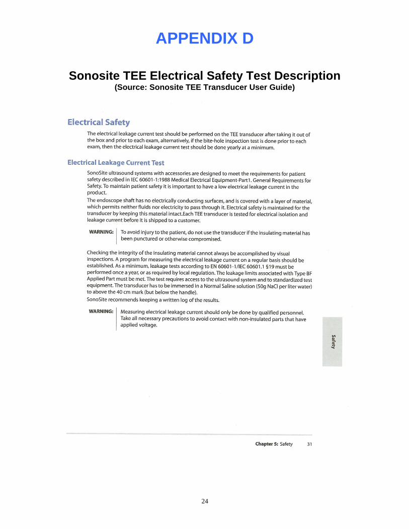
Sonosite, Inc. (Bothell, WA) has been an advocate of electrical leakage current testing for TEE transducers since the introduction of their own TEE transducer. In their TEE Transducer User Guide (pages 31-33) they highly recommend periodic electrical safety testing. Language from this publication (top of page 31) is as follows:
“The electrical leakage current test should be performed on the TEE transducer after
taking it out of the box and prior to each exam, alternatively, if the bite-hole inspection
test is done prior to each exam, then the electrical leakage current test should be done
yearly at a minimum.”
The “bite hole inspection test” referred to in the Sonosite, Inc. TEE Transducer User Guide publication involves setting up a water bath with a liquid medium that is electrically conductive to a specified level (water mixed with 50g NaCl/liter of water), using a Digital Multimeter calibrated to NIST traceability, and a copper or aluminum sheet with an area of at least 25 cm
2. The TEE transducer is then submersed in the water bath with the endoscopic
shaft placed into the liquid up to the 40 cm mark. Readings are taken and compared to desired results. This test is recommended as a possible alternative to the electrical safety test (described in detail below using the BC Biomedical ULT-2000 Series), but it would actually be more time consuming than the electrical safety test described below, and could not be combined with the normal disinfection process. Also, because this test utilizes a simple digital multimeter, it is a DC-only low voltage test, and it will not capture capacitive electrical leakage currents that may be present during normal use of the ultrasound transducer with the ultrasound system powered by a customary AC power system at 50 or 60 Hz.
The Sonosite TEE Transducer User Guide publication can be downloaded from the Sonosite, Inc. company website at the following location: http://www.sonosite.com/content/view/55/439/ . Simply scroll to the bottom of the page to find it. You can also see Appendices D, E. and F of this document for detailed information, or simply follow this embedded link to access the file at the Sonosite web site.
Since early 2006, Sonosite, Inc. has purchased and offered for resale to their customers as an accessory item to their TEE transducers, the Fluke ULT-800 instrument for electrical safety testing.

5
Siemens Medical Solutions is probably the most pro-active diagnostic ultrasound manufacturer in the market today when it comes to advocating TEE transducer electrical leakage current testing. Since April, 1993, Siemens Medical Solutions (Mountain View, CA) has been offering the DALE 800A TEE Transducer Leakage Current Tester to its TEE transducer customers as an accessory item, under the Siemens Medical Solutions brand label. In the Siemens DALE 800A TEE Transducer Leakage Current Tester Instruction Manual, the testing method outlined is exactly the same as that shown in Figure 2 below. The following language appears in the Siemens manual:
“The hand-held battery-operated Tester is designed for use during the routine transducer
cleaning procedure conducted between patient examinations.”
The illustration in Figure 2 below is the recommended test setup that Siemens Medical Solutions gives to their customers in the DALE 800A TEE Transducer Leakage Current Tester Instruction Manual:
Figure 2 Recommended TEE Transducer Test Setup Specified by Siemens Medical Solutions
As of the release date of this document, Siemens Medical Solutions markets the DALE800A TEE Transducer Leakage Current Tester on a worldwide basis and strongly endorses TEE electrical leakage current testing with its customers, as well as the specific testing methodology outlined in this document. See Appendix A for product specifications on the Siemens Medical Solutions DALE 800A instrument.
GE Healthcare is another pro-active ultrasound system manufacturer when it comes to advocating electrical leakage current testing of their TEE transducers. For example, in the GE Service Note # SN76018 (October 2, 2000), they outline an electrical safety testing protocol that is very similar to the one described in detail in this document. On page 2 of this service note, the following is stated:
“The electrical leakage current in the probe can alternatively be measured in a
simplified test without the access to the ultrasound scanner, by using the procedure

6
described below. The test described below is not a complete safety test. It is focused on
the most important insulation test for this product”.
The test setup outlined in this GE service note can be seen in Appendix G of this document. In this same service note, GE Healthcare states the following on page 4 relative to electrical leakage current testing on TEE transducers in general:
“GE Vingmed Ultrasound AS recommends that leakage current testing be carried out on
a regular basis to obtain the best possible patient safety. Also, a leakage current test
should be conducted prior to the use of the probe in any surgical procedure.”
Philips Medical Systems has a history of recommending routine electrical leakage current testing of their TEE transducers that dates back to the Hewlett Packard and Agilent days. It was Hewlett Packard that initially established a working relationship with Dale Technology, Inc. of Thornwood, NY in the late 1990’s regarding the use and recommendation of the DALE800 to their ultrasound customers. At that time, the DALE800 was the only commercially available dedicated ultrasound transducer electrical leakage current testing solution. Currently, Philips continues to advocate electrical leakage current testing on their TEE transducers with their customers, as part of an ultrasound “system” approach. In their TEE Proper Care and Handling Manual (Publication # 4535 611 90271 Rev B), they have the following comments regarding electrical safety concerns with TEE transducers:
“Cuts in the transducer cable or cracks in the housing can destroy the electrical safety
features of the transducers.”
“Bites can cause electrical hazards or mechanical malfunction.”
“Cuts in the transducer insulation can result in current leakage and may lead to serious
patient electrical hazards. In addition, fluid that enters the gastroscope via the cut will
cause electrical and mechanical operational problems.”
In some of their latest ultrasound system user manuals (specifically, manuals that are involved with systems that utilize TEE or other “invasive” types of ultrasound transducers), Philips Medical Systems includes detailed electrical safety testing instructions that are highly recommended to help determine of there is a hole of any kind in the transducer outer insulating barrier. Bite holes or cuts in this insulation barrier could lead to elevated levels of electrical leakage currents, consequently putting the patient at risk. Philips Medical Systems also warns against conducting transducer electrical safety tests by making simple DC measurements on their transducers, and further claims that such testing procedures yield inaccurate results regarding electrical leakage currents in transducers. The prescribed testing method offered by Philips Medical Systems involves the immersion of the TEE and/or other type of “invasive” ultrasound transducer in a saline solution, typically described within this document.
Toshiba Medical America is yet another advocate of routine electrical leakage current testing of their TEE transducers with their customers. In their TEE transducer Operation Manuals, Toshiba recommends an electrical leakage current test prior to each clinical procedure involving the transducer. They have an electrical leakage current testing solution in place (the Hioki Model 3451 Digital Megohm Insulation HiTester
2) and they include this tester with each TEE transducer that they sell. A diagram of the recommended
test setup for the Toshiba line of TEE transducers, utilizing the Toshiba supplied tester appears in Figure 3 below.
2 The Hioki 3451 Digital Megohm HiTester is a DC Insulation Tester and it tests the transducer insulation barrier with DC voltage only. It will not pick up
any capacitive electrical leakage currents that may exist in the transducer during actual use on a conventional AC power systems running at 50 or 60 Hz.

7
Figure 3
Recommended TEE Transducer Test Setup for Toshiba TEE Transducers Using the Toshiba Tester
(Hioki Model 3451 Digital Megohm Insulation HiTester)3
Toshiba Medical lists the following safety recommendation in their Operation Manual For Multiplane Transesophageal Transducer Model PET-510MB (2B701-591E*G):
“Checks Before Use… Checks before system power ON… Electrical Safety Inspection
(inspection using the safety kit)… Perform electrical safety inspection using the safety kit
to check for damage to the transducer which may not be visible.”
In general, this level concern over transducer electrical leakage currents is slowly but surely expanding to other types of “invasive” ultrasound transducers such as those used during laparoscopic procedures. Other major medical device manufacturers in the ultrasound arena are also beginning to make such recommendations to their customers concerning not only TEE but other types of invasive ultrasound transducers, and the need for electrical leakage current testing on them. Once again, the typical clinical application of these types of transducers finds them having been inserted at least several inches into a body cavity or through some type of an incision in the body, thus violating the human body’s natural protection (the outer layers of otherwise dry skin) from electrical macroshock and microshock conditions.
The effects of even the smallest levels of electrical leakage currents on the heart muscle and other internal organs has been studied for over thirty years, and the potential risks are still viewed as critical ones, especially with such currents in close proximity to the heart, as in the typical application of a TEE transducer.
8
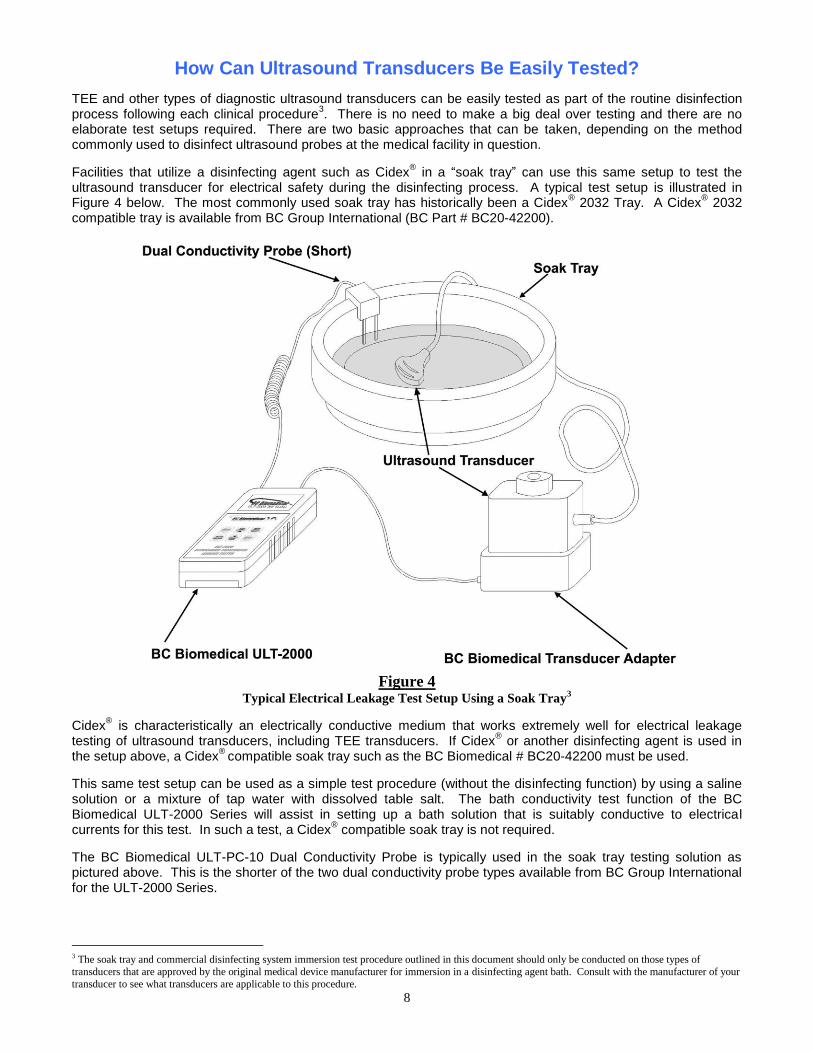
How Can Ultrasound Transducers Be Easily Tested?
TEE and other types of diagnostic ultrasound transducers can be easily tested as part of the routine disinfection process following each clinical procedure
3. There is no need to make a big deal over testing and there are no
elaborate test setups required. There are two basic approaches that can be taken, depending on the method commonly used to disinfect ultrasound probes at the medical facility in question.
Facilities that utilize a disinfecting agent such as Cidex® in a “soak tray” can use this same setup to test the
ultrasound transducer for electrical safety during the disinfecting process. A typical test setup is illustrated in Figure 4 below. The most commonly used soak tray has historically been a Cidex
® 2032 Tray. A Cidex
® 2032
compatible tray is available from BC Group International (BC Part # BC20-42200).
Figure 4
Typical Electrical Leakage Test Setup Using a Soak Tray3
Cidex® is characteristically an electrically conductive medium that works extremely well for electrical leakage
testing of ultrasound transducers, including TEE transducers. If Cidex® or another disinfecting agent is used in
the setup above, a Cidex®
compatible soak tray such as the BC Biomedical # BC20-42200 must be used.
This same test setup can be used as a simple test procedure (without the disinfecting function) by using a saline solution or a mixture of tap water with dissolved table salt. The bath conductivity test function of the BC Biomedical ULT-2000 Series will assist in setting up a bath solution that is suitably conductive to electrical currents for this test. In such a test, a Cidex
® compatible soak tray is not required.
The BC Biomedical ULT-PC-10 Dual Conductivity Probe is typically used in the soak tray testing solution as pictured above. This is the shorter of the two dual conductivity probe types available from BC Group International for the ULT-2000 Series.
3 The soak tray and commercial disinfecting system immersion test procedure outlined in this document should only be conducted on those types of
transducers that are approved by the original medical device manufacturer for immersion in a disinfecting agent bath. Consult with the manufacturer of your
transducer to see what transducers are applicable to this procedure.

9
Where a commercially available ultrasound transducer disinfecting system such as the Automated TD 100® TEE
Probe Disinfector manufactured by CS Medical is used (shown in Figure 5 below), the BC Biomedical ULT-2000 Series can also be easily utilized before or after the disinfecting process, for a combination disinfecting and electrical leakage current testing process with such systems.
Figure 5
CS Medical TD 100® Disinfecting System
The special-purpose BC Biomedical ULT-PC-20 Dual Conductivity Probe is typically used in this type of application. A generic setup using a commercially available disinfecting station is illustrated in Figure 6 below.
Figure 6
Generic Functional Diagram of a Typical Electrical Leakage Test Setup Using a Commercial Disinfecting System
No matter which of the above setups is used, the actual testing is performed in the same manner. The ultrasound transducer to be tested is connected to the test device (BC Biomedical ULT-2000 Series) through a dedicated

10
ultrasound transducer adapter (as shown in Figures 4 and 6), also available from BC Group. The leakage current test is performed after the patient contact or “application” end of the transducer is immersed in the bath solution (typically Cidex
® or saline solution). As soon as the ULT-2000 instrument is turned on, an automatic instrument
self-test is performed. A test load is switched into the output circuit. The voltage is measured and internal circuitry is confirmed to be working correctly. This same test is performed prior to each electrical leakage test, to ensure test accuracy and quality. To further ensure a quality electrical leakage current test, the conductivity of the bath medium is tested immediately prior to each electrical leakage current test. If the bath conductivity is sufficient, then the electrical leakage current test is performed according to the desired test voltage and frequency (typically specified by the ultrasound manufacturer but the ULT-2000 Series also supports generic test setups as part of the basic instrument firmware). The actual test results are compared to the limits for the transducer being tested (or to the generic limits also supplied in the instrument) and a Pass / Fail indication is given. If the ULT-2000 Series instrument was initially set up to display actual leakage current readings, these readings will also be shown.
Can Non-Technically Oriented Personnel Perform These Tests?
Yes. Electrical safety testing of TEE and other types of diagnostic ultrasound transducers does not require the user to know anything about electrical leakage currents or electrical safety testing protocols. Anyone that can read and properly interpret the words “Pass” and “Fail” can adequately perform a proper electrical safety test on a transducer with the BC Biomedical ULT-2000 Series.
Whether the instrument is set up (by the user) to provide actual numeric values or not, the ULT-2000 Series instrument clearly reports a Pass or Fail result that is easily interpreted by anyone. It’s that simple!
Can Technically-Oriented Personnel Get Important Measurement Data?
Yes. The user can select from two modes of operation in the ULT-2010 instrument (compared to three modes offered by the ULT-2020 instrument). The Pass / Fail mode as outlined above is intended for non-technical users such as ultrasound sonographers, central sterile supply technicians, etc. For biomedical and clinical engineering professionals, the Numeric Test Results mode reports the actual test results and leakage current limits in addition to the Pass / Fail results. The Metering mode of the ULT-2020 instrument allows the user to constantly monitor electrical leakage currents in real time to assess the impact of probe movement, flexing, straining, etc.

11
Competitive Product Comparison4
A brief overview of the BC Biomedical ULT-2000 Series as compared to the leading competitive products on today’s market is as follows:
Feature / Product BC ULT-2010 BC ULT-2020 DALE800
5 Siemens
DALE800A6
Fluke ULT-800
7
User-selectable operating modes Yes Yes No No No
User-selectable test voltages Yes Yes No No No
User-selectable leakage current limits Yes Yes No No No
User selectable test voltage frequency Yes Yes No No No
Pass / Fail test results Yes Yes Yes Yes Yes
Numeric test results data displayed Yes Yes No No No
On-board storage of test results No Yes No No No
Manufacturer & Model probe database Yes Yes No No No
Ability to print test results report Yes Yes No No No
Real-time continuous metering mode No Yes No No No
Single 9-volt battery operation Yes Yes Yes Yes Yes
AC power operation for long term testing Yes Yes No No No
RS232 communications port Yes Yes No No No
Download stored test results to PC No Yes No No No
Large graphical display with backlighting Yes Yes No No No
Real-time clock & calendar function for time and date stamping test results
Yes Yes No No No
Utility PC software available Yes Yes No No No
Accurate and reliable readings down to 0.5 microamps
Yes Yes No No No
Accurate and reliable readings up to 500 microamps
Yes Yes No No No
Bath conductivity test Yes Yes Yes Yes Yes
Aggressive bath conductivity test8 Yes Yes No No No
Compatibility with Dale / Fluke adapters and probes
Yes Yes Yes Yes Yes
The Difference Starts with the Bath Conductivity Test
From the start, the BC Biomedical ULT-2000 Series does it better than other commercially available dedicated testing solutions. Prior to the ULT-2000 Series, commercially available test systems simply tested the liquid medium bath at a single voltage level and reported a Pass result at a relatively low conductivity level. Typical values at the fixed point 120 VAC, 60 Hz bath conductivity test for a Pass result range from 133 microamps to 246 microamps. This amounts to a bath resistance level of 0.902 Megohms to 0.488 Megohms, respectively, for those Ohm’s Law enthusiasts out there. More will be stated on why these levels are not adequate for reliable testing below.
The BC Biomedical ULT-2000 Series pushes the limit and ensures adequate bath conductivity to catch all transducer leakage current limits, no mater how big or small. The ULT-2000 conductivity test is performed at the minimum user-selectable voltage of 90 VAC. The test also looks for a minimum of 500 microamps of current flow at this voltage, in order to establish a Pass status for the bath conductivity test. This calculates to a bath
resistance of 0.180 Megohms, which is 2.7 times better than the best case scenario and 5 times better than the worst case scenario of the other commercially available testers. What does this all mean and why is it important?
4 Competitive product information presented is based upon all available information in the public sector, including but not limited to the following sources; product specification documents, product data sheets, product operator manuals, product information as found on the manufacturer’s website. 5 Product specifications can be seen in Appendix C. 6 Product specifications can be seen in Appendix A. 7 Product specifications can be seen in Appendix B. 8 Defined as testing the bath conductivity at the minimum user-selectable test voltage while testing for at least 500 microamps of current flow through the
bath medium

12
For the technically savy user…
First, here is the explanation for those technically-inclined Ohm’s Law enthusiasts referred to above. Consider the simple series equivalent circuit below as being representative (functionally equivalent) of our soak tray test setup.
Figure 7
Simple Series Equivalent Circuit of Bath Resistance and Transducer Insulation Barrier Resistance
Consider Vs to be the test instrument voltage, Rb as the bath resistance, and Rt as the transducer under test insulation barrier resistance. Consider the current flow in the circuit to be the leakage current. This example is a little over-simplified, but it will work for this analysis. Use Vs = 120 volts. Using Ohm’s Law (V = IR), the total current flow through the circuit will be the following:
I = Vs / (Rb + Rt) or I = 120 / (Rb + Rt)
For the simple series circuit in Figure 7 above, we essentially want the resistance of the bath (Rb) in the soak tray to be as low as possible, and much lower than the equivalent resistance of the insulation barrier of the transducer (Rt). Otherwise, it will interfere with the leakage current readings and may result in a false Pass / Fail test status.
If we use a 100 microamp Pass / Fail limit for any given transducer, then at leakage currents (series circuit current flow) above 100 microamps, we have a Fail condition and at currents below 100 microamps we have a Pass condition. This would calculate to a transducer insulation barrier equivalent resistance (Rt) of 1.2 Megohms as the borderline between the Pass and Fail conditions. For the sake of this example, let’s set the actual value of Rt to 1 Megohm. In our simple series circuit above, and in an ideal, non-real world example, Rb would ideally be 0 ohms. Thus the current flow in the circuit would be 120 microamps, which constitutes a Fail condition (remember, the Pass / Fail threshold is 100 microamps). Now let’s get back to the real world and add the Rb value of 0.180 Megohms that the ULT-2000 Series looks for to give the bath conductivity test a Pass status. The current flow in our simple series circuit is now 101.69 microamps. The ULT-2000 Series would report a Fail test status in this example.
Now let’s look at how the competitive instrument that simply looks for a 133 microamp conductivity level to report a Pass status on the bath test does. From the explanation above, at this level of bath conductivity, the equivalent resistance of the bath can be calculated as 0.902 Megohms. This is our new value for Rb. Adding this value of Rb to the Rt value of 1 Megohm results in a series circuit current flow of 63.09 microamps! The test result is a Pass! But the real current (leakage current) is more like 120 microamps. What happened? The low conductivity (high resistance) of the bath (Rb) got in the way and reported a false Pass condition on a bad transducer!
Finally, let’s look at how the competitive instrument that looks for a 246 microamp conductivity level to report a Pass status on the bath tests does. Again, from the explanation above, at this level of bath conductivity, the equivalent resistance of the bath can be calculated as 0.488 Megohms. This is our new value for Rb. Adding this value of Rb to the Rt value of 1 Megohm results in a series circuit current flow of 80.65 microamps! The test result is still a Pass! But once again the real current (leakage current) is more like 120 microamps. What happened? Once again, the low conductivity (high resistance) of the bath (Rb) got in the way and reported a false Pass condition on a bad transducer!
This example may be over-simplified but it certainly illustrates the role of the test bath conductivity level in the reporting of Pass / Fail results on transducers. In the example above, the BC Biomedical ULT-2000 Series reports the results correctly, while the competitive instruments report false Pass conditions, based solely on the role of the bath resistance. The much more aggressive bath conductivity test of the ULT-2000 Series instruments goes a long way to help ensure more accurate and more reliable test results, as compared to other commercially available testers.

13
For the non-technically oriented but interested users out there…
If you have no idea what Ohm’s Law is and you don’t care to find out, as we have already stated, the much more aggressive bath conductivity test of the ULT-2000 Series instruments goes much further in ensuring the accuracy and reliability of the test results on your TEE and other types of ultrasound transducers. In the specific example illustrated above, the transducer was bad, as it had approximately 120 microamps of electrical leakage at a 120 volt test voltage. The ULT-2000 Series instrument properly reported this Fail status. Based upon this analysis, the other commercially available testers would probably have falsely reported Pass results for this same transducer!
Dealing With Real World Parameters
The fact is that ultrasound manufacturers specify the following parameters in their detailed specifications on their ultrasound transducers, relative to electrical safety testing:
Test voltage
Test voltage frequency
Lower leakage current limit (actual test value must exceed this value to Pass)
Upper leakage current limit (actual test value must be less than this value to Pass)
Unlike other commercially available dedicated testers, the BC Biomedical ULT-2000 Series deals with all of these “real world” variables. Test voltage can be set by the use in the range of 90 to 275 volts at either 50 or 60 Hz. This capability is in response to customer demands in countries other than North America, where nominal line voltages are higher (e.g. 230 volts) and the frequency is different from North America (50 Hz instead of 60 Hz). There are some customers that even argue that the test voltage should be 10% above the nominal line voltage. The ULT-2000 Series responds to all of these demands.
There are some ultrasound manufacturers out there that have transducers with characteristic leakage currents that are as high as 300 to 400 microamps! These are the actual manufacturer specifications for select transducers. The current systems on the market do not address these real-world examples of transducers that have higher levels of electrical leakage currents when tested according to the prescribed means as illustrated in this document. The ULT-2000 Series instruments address these specific transducers with an upper-end range of 500 microamps.
Lower (low-end) leakage current limits are also a reality of manufacturer specifications. Transducers are “validated” by a minimum leakage current level as low as 2 microamps. The ULT-2000 Series instruments will measure reliably and accurately down to 0.5 microamps. The currently available competitive instruments on the market cannot accurately or reliably resolve leakage current levels less than approximately 20 microamps. One of these manufacturers has actually had to supply some of its customers with leakage current “dummy loads” designed to fool their instrument into thinking there was a higher amount of leakage than was actually present at this low-end with a specific type of transducer, just to get it to Pass the lower limit leakage current test. Is this how you want your leakage tester to work?
Finally, in order to make life even easier for the users of the ULT-2000 Series instruments, there is a manufacturer and model specific transducer database on board in the instrument that contains all of these “real world” variables for each transducer entered into the database. BC Group International has actually been working with several ultrasound manufacturers on supplying actual manufacturer specifications regarding characteristic leakage currents and set limits for Pass / Fail results according to these specifications. This work will continue well into the future.
Why Test With AC Voltages Instead of DC Voltages?
The ULT-2000 Series tests at AC voltages rather than DC for two main reasons. First, the capacitive leakage currents that will be present in an ultrasound system and transducer that is normally powered at AC line voltage will be present and will be detected in the test. At DC voltages, they will not be present nor will they be read by the tester. This would be a false test. Secondly, testing at DC voltages could set up a voltaic cell
9 condition, with
9 See Appendix H for additional information on a voltaic cell.

14
the metal of the transducer and test electrode in the Cidex® or salt bath forming the two electrodes and an
electrolyte. This condition would result in inaccurate readings
Can Test Results Be Archived for Legal Liability Purposes?
Yes. Unlike other commercially available dedicated testing systems, the BC Biomedical ULT-2000 Series offers the ability to print test results to an accessory printer that is attached to the RS232 communications port of the ULT-2000. A ruggedized serial printer is available from BC Group International as an optional accessory item to the ULT-2000 Series under Part # BC20-42300.
This printer will work with either the ULT-2010 or ULT-2020 instruments. With the ULT-2020 and the PC Utility Software for the ULT-2000 Series, the user can actually print test results form the PC as well.
Test results printed from the ULT-2000 Series instrument will have the date and time of the test listed, thanks to the real-time clock and calendar function of the ULT-2000 Series. Stored test records will also contain the date and time of test as part of the stored data. A sample printout of these test results can be seen in Appendix I.
Test results can also be archived via the ULT-2000 Series PC Utility Software to a PC (ULT-2020 only), and can be printed at any time from the PC to any Windows
® compatible printer.
PC Utility Software Makes It Easy
The BC Biomedical ULT-2000 Series PC Utility Software is a special Visual Basic software utility for the ULT-2000 Series that makes it easy to perform functions like adding or editing information in the transducer manufacturer and model database (both ULT-2010 and ULT-2020), configuring the instrument (ULT-2010 and ULT-2020), operating the tester remotely (ULT-2020 only), and downloading stored test results (ULT-2020 only).
Ultrasound Transducer Adapter Compatibility
Users of competitive instruments such as the Dale Technology DALE800, the Fluke Biomedical ULT-800, and the Siemens Medical Solutions DALE800A, who have already invested substantially in a library of dedicated ultrasound adapters, will find the BC Biomedical ULT-2000 Series to be 100% compatible with the adapters previously purchased. These users can take full advantage of the advanced level of features and functionality offered by the ULT-2010 and ULT-2020 instruments by simply purchasing one of these instruments and using it with existing adapters. Users who need additional adapters will also find that the adapters available from BC Group International are at a significant cost savings compared to those available from our competitors.

15
Available Transducer Adapters
At the time of publication of this document, the following complement of dedicated ultrasound transducer adapters is available from BC Group International for use with the BC Biomedical ULT-2000 Series, as well as with competitive dedicated testing systems that utilize these types of adapters:
Ultrasound Transducer Manufacturer
Ultrasound Platform Transducer Compatibility
BC Biomedical Part #
Sonosite 180/180+, Titan ICT7-4, ITC8-5, C60, etc.
ULT-PA-11
Siemens/Acuson V5M (TEE), V7M (TEE), EV8-C4, etc.
ULT-PA-10
Siemens Antares EC9-4, etc. ULT-PA-12
Siemens/Acuson 156-pin Transducers ULT-PA-13
Philips/ATL C9-5, C8-4v, MPT7-4 (TEE), etc.
ULT-PA-17
Philips/ATL S7-2 (TEE), S7-3t (TEE), C8-4v, C9-5, etc.
ULT-PA-17
GE 6T (TEE), 9T (TEE), E8C, etc.
ULT-PA-16
GE Other ULT-PA-16
For an up-to-date listing of transducer adapters available from BC Group International, simply go to www.bcgroupintl.com.
Advanced Features for Advanced Users
Independent ultrasound service companies like Echoserve of Golden, CO10
(www.echoserve.com), that use the BC Biomedical ULT-2000 Series product, will find some of the advanced and special features of the BC Biomedical ULT-2000 (available in the ULT-2020 Model) extremely useful. The special “Monitoring Mode” of the ULT-2020 (the advanced testing model of the ULT-2000 Series) allows real-time continuous testing for electrical leakage currents while the ultrasound probe cable is flexed and bent in order to evaluate whether positioning or stress on the cable has any effect on electrical leakage currents.
The ability to store up to 99 sets of test results in the ULT-2020 adds to the flexibility of the instrument. Test results can be printed to the optional printer immediately following the leakage test or they can be recalled from memory at a later time and printed then.
The ULT-2000 Series PC Utility Software allows remote control of the ULT-2020 and allows the user to transfer the stored test results form the instrument to the PC for printing or archiving.
Competitive Product Cost Comparison
Even with all of the added features and functionality of the BC Biomedical ULT-2000 Series, system cost is not something that our customers will find to be prohibitive in any way. A fully-functional test system for both the BC Biomedical ULT-2000 Series and the leading competitive unit could easily include the following items:
TEE Leakage Current Tester
Conductivity Test Probe
Two (2) dedicated ultrasound transducer adapters
Soak Tray
The “system cost”11
of the leading competitive unit12
, with all of the items specified above, could be as high as $ 2,529, depending upon the transducer adapters selected. The comparable system, utilizing the BC Biomedical
10 Echoserve is a customer of BC Group International and uses the ULT-2000 Series instruments in their business. 11 Based upon U.S. List Price of individual part numbers at the time of publication of this document.. 12 Fluke Biomedical ULT-800 pricing is referenced in this comparison.

16
ULT-2000 Series product and the adapters for the same transducers would cost $ 2,190. That’s a savings of 13%, even with all of the added functionality of the BC Biomedical ULT-2000 Series.
Conclusion
The evidence regarding the need for electrical leakage current testing between patient applications of TEE and other “invasive” types of ultrasound transducers, as gathered from the major diagnostic ultrasound system medical device manufacturers represented in this document, is compelling. This testing is clearly prescribed at the end-user level. Some manufacturers even go as far as recommending suitable test setups
13. Accordingly,
end-users of these TEE and other types of “invasive” types of transducers are strongly advised to comply with these original manufacturer recommendations in order to: 1) enhance the quality of patient care and safety, and 2) avoid legal liability implications in the case of a patient treatment event in the process of using such a transducer. The only logical conclusion would be to perform these electrical safety tests on these transducers prior to each clinical procedure. The easiest and most efficient way to perform these tests would be to implement the test methodology illustrated within this document, utilizing the “next generation” BC Biomedical ULT-2000 Series instruments.
Figure 8
Typical Electrical Leakage Test Setup Using a Soak Tray14
13 See Figures 2 and 3, and Appendices for manufacturer recommended test setups. 14 The soak tray and commercial disinfecting system immersion test procedure outlined in this document should only be conducted on those types of transducers that are approved by the original medical device manufacturer for immersion in a disinfecting agent bath. Consult with the manufacturer of your
transducer to see what transducers are applicable to this procedure.

17
ULT-2000 Series Product Specifications15
15 Specifications are accurate as of the date of release of this document. Specifications are subject to change without prior notice.
SOURCE, LEAKAGE AND CONDUCTIVITY
SOURCE (CHALLENGE) VOLTAGE
90 - 275 VAC, ± 1% FS 500 µA Max Load
SOURCE (CHALLENGE) FREQUENCY
50 or 60 Hz, ± 0.5 Hz
LEAKAGE CURRENT MEASUREMENT
0.50 - 10.00 µA, ± 0.5 µA 10.0 - 250.0 µA, ± 1% Range 250.0 - 500 µA, ± 1% Range
CONDUCTIVITY CURRENT MEASUREMENT
0.5 - 500 µA, ±1% FS
CONNECTIONS
ELECTRICAL AND MISC.
BATTERY 9V Lithium Battery
(ANSI/NEDA 1604LC or equivalent)
BATTERY ELIMINATOR
10 VDC, 300mA
BC20-21103 (USA Version) BC20-21106 (EURO Version)
POWER CONSUMPTION
ON < 300 mA
OFF < 250 uA
BATTERY LIFE CONTINUOUS > 100 Full Tests
OFF 1 year
RS-232 COMMUNICATIONS CONNECTOR
Seven (7) pin Mini-DIN Pinout:

18
ELECTRICAL AND MISC. (continued)
RS-232 COMMUNICATIONS SETTINGS
BAUD 115200
DATA BITS 8
START BITS 1
STOP BITS 1
PARITY none
HANDSHAKING none
PHYSICAL & ENVIRONMENTAL
DISPLAY 128 X 64 Pixels Graphical LCD,
White LED Backlight
MEMORY SETUP EEPROM, All parameters
RETENTION 10 Years w/o Power
CONSTRUCTION ENCLOSURE ABS Plastic
OVERLAY Back-printed Lexan
SIZE 7.27 x 3.97 x 1.80 Inches (184.7 x 100.8 x 45.7 mm)
WEIGHT ≤ 1.1 Lbs (0.50 kg)
OPERATING RANGE 15 to 30 °C
(59 to 86 °F)
STORAGE RANGE -40 to 60 °C
(-40 to 140 °F)

19
Technical References
Sonosite TEE Transducer User Guide, Publication No. P05341-02 06/2005, Copyright Sonosite, Inc., Bothell, WA (Download file @ http://www.sonosite.com/Service-Support/support-documents.html)
GE Healthcare Service Note # SN76018, October 2, 2000, Copyright GE Healthcare
TEE Proper Care and Handling (Publication # 4535 611 90271 Rev B), Copyright 2004, Koninklijke Philips Electronics N.V.
iE33 Ultrasound System User Reference (Publication # 4535 612 82431 Rev A), Copyright September, 2006, Koninklijke Philips Electronics N.V.
Operation Manual for Safety Kit for Multi-Plane Transesophageal Transducer (2B701-753E), Toshiba Corporation, Copyright 2003
Operation Manual for Multiplane Transesophageal Transducer Model PET-510MB (2B701-591E*G), Toshiba Medical Systems Corporation, Copyright 2002 - 2006
Common Ultrasound Probe Failures (Copyright 2006) , Sonora Medical Systems (www.4sonora.com) , Author: G. Wayne Moore, B.Sc., MA
Dale Technology DALE800 Product Overview Document, Fluke Biomedical, Author: Michael R. Erwine, Copyright June, 2003 (Download file @ www.daletech.com/main/DALE800ProductOverview-RevA.pdf)
Siemens Medical Solutions DALE 800A TEE Transducer Leakage Current Tester Instruction Manual, Copyright April, 2003 (Co-authored by Michael R. Erwine)
Dale Technology DALE800 Operator Manual (Out of production – no longer available), Copyright Dale Technology, Inc.
Fluke Biomedical ULT-800 Operator Manual, Copyright Fluke Biomedical (Download file @ http://global.flukebiomedical.com/busen/support/manuals/default.htm)
IEC 60601-1:1988 Medical Electrical Equipment–Part 1. General Requirements for Safety.
UL 60601-1:2003, Underwriters Laboratories Medical Electrical Equipment-Part 1. General Requirements for Safety.
ULT-2000 White Paper – Rev 4.doc

20
APPENDICES
All documents and information contained in the following Appendices have been
obtained from various sources within the public sector, and do not represent confidential
information or trade secrets of any kind. Recognition of ownership and copyright is
hereby given to the companies and manufacturers whose product and other types of
information are represented here in this document for informational purposes. Original
ownership and copyright of this documentation remains with these companies.

21
APPENDIX A
Siemens DALE 800A Instrument Specifications (Source: Siemens Medical Solutions DALE 800A Instruction Manual)

22
APPENDIX B
Fluke Biomedical ULT-800 Instrument Specifications
(Source: Fluke Biomedical ULT-800 Users Guide)

23
APPENDIX C
Dale Technology DALE800 Instrument Specifications
(Source: Dale Technology, Inc. DALE800 Instruction Manual)
SPECIFICATIONS
Power: 9-Volt Alkaline Battery
No. Of Uses: Approximately 1,000 uses on a single battery
Conductivity: Limit to pass: greater than 133 µA ± 1%
Leakage: Limit to pass: less than 100 µA ± 1%
Dimensions: 6.5 x 3.7 x 1.5 in (17 x 10 x 4 cm)
Weight: 12 oz (340 g)
Environmental: Operation Temperature 15º to 40º C
Storage Temperature 15º to 65º C
Relative Humidity 90% Max
24
APPENDIX D
Sonosite TEE Electrical Safety Test Description
(Source: Sonosite TEE Transducer User Guide)

25
APPENDIX E
Sonosite TEE Bite-Hole Test (1
st page)
16
(Source: Sonosite TEE Transducer User Guide)
16 Because this test utilizes a simple digital Multimeter, it is a DC-only low voltage test, and it will not capture capacitive electrical leakage currents that may
be present during normal use of the ultrasound transducer with the ultrasound system powered by a customary AC power system at 50 or 60 Hz.

26
APPENDIX F
Sonosite TEE Bite-Hole Test (2
nd page)
17
(Source: Sonosite TEE Transducer User Guide)
17
Because this test utilizes a simple digital Multimeter, it is a DC-only low voltage test, and it will not capture capacitive electrical leakage currents that
may be present during normal use of the ultrasound transducer with the ultrasound system powered by a customary AC power system at 50 or 60 Hz.

27
APPENDIX G
GE Healthcare Simplified Leakage Current Setup
(Source: GE Service Note # SN76018)

28
APPENDIX H
Voltaic Cells
(Source: http://hyperphysics.phy-astr.gsu.edu/hbase/chemical/electrochem.html)
A Voltaic Cell is an electrochemical cell that causes external electric current to flow. It can be created by using two different metals since metals differ in their tendency to lose electrons. For instance, Zinc more readily loses electrons than copper, so placing zinc and copper metal in solutions of their salts can cause electrons to flow through an external wire which leads from the zinc to copper. The presence of this condition sets up a relative inaccuracy in a leakage current test setups as the one shown in this document, and should not be used to test TEE and other types of “invasive” diagnostic ultrasound probes.
Philips Medical Systems has the following to say in their iE33 Ultrasound System User Reference Manual (Publication # 4535 612 82431 Rev A) relative to DC voltage testing of TEE and others types of “invasive” transducers:
Example of a Simple Voltaic Cell
For additional information on Voltaic Cells, and to complete the analysis (explanation) started above, you can simply visit the following url: http://hyperphysics.phy-astr.gsu.edu/hbase/chemical/electrochem.html Or simply search the Internet for “voltaic cells” using your favorite search engine.

29
APPENDIX I
Sample Printout of Test Results from ULT-2000

30
APPENDIX J
History of BC Group International, Inc.
BC Group was founded in 1988. In 2000, we began manufacturing our own product line under the now familiar Green and Gold "BC Biomedical" label. In January of 2005, Lloyd Industries, the company that engineered and manufactured most of the BC Biomedical brand products, purchased BC Group. This acquisition has allowed our products and services to expand at an even faster pace. BC Group, under the "BC Biomedical" brand, is now the second largest manufacturer of Biomedical Test and Measurement Equipment in the world. Our philosophy with BC Biomedical products runs counter to the current trend of "one-size-fits-all." We offer families of products that provide the users with a choice of models so they can pick the features they need at a price they can afford. We will very shortly be releasing software that will allow our ESU-2400 Electrosurgery Analyzer to not only record data from testing, but to actually run the ESU that it is testing. BC Group has a major commitment to Quality at all levels of our operation. The entire company is ISO 9001:2008 and 13485:2003 Registered. Our Service Center is compliant with both ANSI Z540 and ISO 17025 with full traceability to NIST. We are Registered with and Inspected by the FDA and follow the Good Manufacturing Practices (GMP) as well as comply with the QSR (Quality Systems Regulation) 21CFR820. Keep checking our website for the latest additions to the BC Biomedical Line.
Website: www.bcgroupintl.com E-mail: [email protected]