ulterra™ with i-pilot - carid.com · ulterra™ with i-pilot ... avoid submerging the complete...
TRANSCRIPT

ULTERRA™ WITH i-PILOT®
BOW-MOUNT TROLLING MOTOROWNER'S MANUAL

Please thoroughly read this user manual. Follow all instructions and heed all safety and cautionary notices below. Use of this motor is only permitted for persons that have read and understood these user instructions. Minors may use this motor only under adult supervision.
ATTENTION: Never run the motor out of the water, as this may result in injuries from the rotating propeller. The motor should be disconnected from the power source when it is not in use or is off the water. When connecting the power-supply cables of the motor to the battery, ensure that they are not kinked or subject to chafe and route them in such a way that persons cannot trip over them. Before using the motor make sure that the insulation of the power cables is not damaged. Disregarding these safety precautions may result in electric shorts of battery(s) and/or motor. Always disconnect motor from battery(s) before cleaning or checking the propeller. Avoid submerging the complete motor as water may enter the lower unit through control head and shaft. If the motor is used while water is present in the lower unit considerable damage to the motor can occur. This damage will not be covered by warranty.
CAUTION: Take care that neither you nor other persons approach the turning propeller too closely, neither with body parts nor with objects. The motor is powerful and may endanger or injure you or others. While the motor is running watch out for persons swimming and for fl oating objects. Persons whose ability to run the motor or whose reactions are impaired by alcohol, drugs, medication, or other substances are not permitted to use this motor. This motor is not suitable for use in strong currents. The constant noise pressure level of the motor during use is less than 70dB(A). The overall vibration level does not exceed 2,5m/sec2.
THANK YOUThank you for choosing Minn Kota. We believe that you should spend more time fi shing and less time positioning your boat. That’s why we build the smartest, toughest, most intuitive trolling motors on the water. Every aspect of a Minn Kota trolling motor is thought out and rethought until it’s good enough to bear our name. Countless hours of research and testing provide you theMinn Kota advantage that can truly take you “Anywhere. Anytime.” We don’t believe in shortcuts. We are Minn Kota. And we are never done helping you catch more fi sh.
REMEMBER TO KEEP YOUR RECEIPT AND IMMEDIATELY REGISTER YOUR TROLLING MOTOR.
CE MASTER USER MANUAL (FOR CE/C-TICK CERTIFIED MODELS)
Thank you for purchasing the Minn Kota Ulterra electric steer trolling motor. This motor provides the ultimate hands-free operation by giving the user automatic stow and deploy and power trim as well as all the other Minn Kota electric steer motor features that users have grown to love. The simplicity of use maximizes your time on the water and ensures you spend your time fi shing. By following the instructions provided in this manual, you will learn how to properly install and operate your new Ulterrra for years of trouble-free use. We encourage you to read this manual thoroughly in order to maximize your product experience.
LOCATING YOUR SERIAL NUMBER
Your Minn Kota 11-character serial number is very important. It helps to determine the specifi c model and year of manufacture. When contacting Consumer Service or registering your product, you will need to know your product’s serial number. We recommend that you write the serial number down in the space provided below so that you have it available for future reference.
You are responsible for the safe and prudent operation of your vessel. We have designed Ulterra to be an accurate and reliable tool that will enhance boat operation and improve your ability to catch fi sh. This product does not relieve you from the responsibility for safe operation of your boat. You must avoid hazards to navigation and always maintain a permanent watch so you can respond to situations as they develop. You must always be prepared to regain manual control of your boat. Learn to operate your Ulterra in an area free from hazards and obstacles.

i-PILOT ULTERRA REMOTEFor complete details on this remote, see page 16 of this manual.
Trim Up Trim Down
Stow/Deploy
FEATURES
Specifi cations subject to change without notice.*This diagram is for reference only and may diff er from your actual motor.
Weedless Wedge 2 Propeller
Cool Quiet Power Motor
Lifetime Warranty Flexible Composite Shaft
Power Trim
Integrated i-PilotControl Head
MOTOR FEATURES
Auto Stow/Deploy
Multi-FunctionFootpedal

INSTALLATION
PARTS INCLUDED
A
BC
D
H
G
E
F
J
I
K
Your new Ulterra comes out of the box with everything you’ll need for direct to boat mounting. This motor can be direct mounted to the boat or coupled with a Minn Kota quick release bracket for ease of mounting and removal. Please review the parts list and tools needed for installation prior to getting started.
PARTS LIST
A. (1) Ulterra Trolling Motor
B. (1) Washer, Prop
C. (1) ⅜"–24 Locknut, Prop
D. (1) Lower Unit Emergency Strap
E. (1) Universal Sonar Extension Cable (Pre-Installed)
F. (1) 3/16" x 1.00" Pin, Prop
G. Weedless Wedge 2 Prop
H. (1) i-Pilot Remote Lanyard(includes lanyard rope with (1) loop clip and (1) carabiner clip)
I. (1) i-Pilot Remote
J. (1) Foot Pedal
K. Mounting Hardware Bag
L. Manual CD (not pictured)
M. Installation Guide (not pictured)

Installation Instructions:1. Remove the four sideplate screws. Remove sideplates to access the mounting holes. (Figure 1)
2. Remove the two 5/16” e-clips retaining the extension damper. Remove the extension damper to expose the front left mounting hole. (Figure 2)
3. Place the motor on the bow of the boat. It is recommended that the motor be mounted as close to the centerline of the boat as possible. Make sure the slot on the underside of the mounting base is aligned with the rubrail of the boat. This will ensure that the shaft has a minimum clearance of 1-1/2” when it is deployed. (Figure 3 & 4)
4. Once the motor is positioned, mark at minimum, four of the six holes that are located farthest apart (at least two on each side). Make sure the area under the mounting location is clear to drill holes and install nuts and washers. Drill through the marked holes using a 5/16” drill bit.
5. Mount the motor to the boat using the provided hardware. Install the hex head bolts and clipped washers on the right side of the motor as viewed from the boat interior. (Figure 5) Motor can then be slid into place utilizing the slots on the motor
Parts Included:
Description Qty.
Screw, 1/4-20 x 2” HHCS SS 6
Screw, 1/4-20 x 0.5 HHCS SS 6
Washer-Clipped, 1/4”, 1” OD 6
Nut, 1/4-20 Nylock SS 6
Washer, 1/4” Flat 18-8 SS 6
Washer-Mounting, Rubber 6
Tools and Resources Required: • Drill• 5/16” Drill Bit• 7/16” Wrench• 9/16” Wrench (for prop)• Wire Ties (for cable routing)• Phillips Screwdriver• Flat Blade Screwdriver
Figure 1 Figure 2
Figure 3 Figure 4
5/16” e-clip Extension Damper
Align Slot with Rubrail
Side Plate
Side Plate Screws
Figure 4
Figure 1
Figure 3
Figure 2
INSTALLATION

base plate. Clipped washer should be oriented with the fl at portion against the mounting base. (Figure 6)CAUTION: Use extra care to avoid pinching/damaging the sensor wires that run along side of the aluminum base extrusion when installing and tightening the motor mounting bolts.
6. Reinstall the extension damper with the shaft facing toward the interior of the boat. Reinstall the e-clips. (Figure 7)
7. Replace the sideplates and sideplate screws by hand using a Phillips screwdriver. (Figure 8)Note: Do not use a power tool to install these screws.
8. Connect the motor to power and sonar cable to depth fi nder using the appropriate adapter cable (sold separately).9. The user has the option of stowing the prop oriented in or out to accommodate diff erent boat cover confi gurations. Follow
the procedure in the Mounting Options section of the owner’s manual to change prop orientation.
Figure 5 Figure 6
Figure 8Figure 7
1/4” Clipped Washer (fl at side facing mounting base)
1/4” Flat Washer
Rubber Mounting Washer
1/4-20 x 2” Screw
1/4-20 Nylock Nut
Shaft Side of Damper
1/4-20 x 2” Screw with 1/4” Clipped Washer (fl at side facing mounting base)
Figure 7 Figure 8
INSTALLATION

MOUNTING OPTIONSThe user has the option of stowing with the prop orented in or out to accommodate diff erent boat cover confi gurations. Follow the procedure below to change prop orientation.
1. Turn power on and deploy motor using the stow/deploy button on footpedal or remote (see the Manual Control section or UlterraFunctions for deploying instructions). CAUTION: When deploying, ensure the motor doesn’t contact boat or trailer.
2. Turn the motor off .
3. Pull out manual trim release handle located on the side of trim housing. (Figure 9)
4. While holding trim release handle, lift up shaft/trim housing and rotate 180 degrees. (Figure 10)5. Lower shaft and trim housing onto the steering housing. Seat trim housing by holding out manual trim release handle and orienting
trim housing onto steering housing. (Figure 11)
6. Turn on power at the motor power button.
7. Stow the motor using the stow/deploy button on footpedal or remote. The lower unit will stow with the prop in the desiredorientation. (Figure 12 & Figure 13)
WARNING: When raising/lowering motor or operating the tilt mechanism, keep fi ngers clear of all
hinge and pivot points and all moving parts.
Figure 10 Figure 11
Figure 9
Figure 12 PROP OUT Figure 13 PROP IN
Trim Handle
INSTALLATION

BOAT RIGGING & PRODUCT INSTALLATIONFor safety and compliance reasons, we recommend that you follow American Boat and Yacht Council (ABYC) standards when rigging your boat. Altering boat wiring should be completed by a qualifi ed marine technician. The following specifi cations are for general guidelines only:CAUTION: These guidelines apply to general rigging to support your Minn Kota motor. Powering multiple motors or additional electrical devices from the same power circuit may impact the recommended conductor gauge and circuit breaker size. If you are using wire longer than that provided with your unit, follow the conductor gauge and circuit breaker sizing table below. If your wire extension length is more than 25 feet, we recommend that you contact a qualifi ed marine technician.An over-current protection device (circuit breaker or fuse) must be used. Coast Guard requirements dictate that each ungrounded current-carrying conductor must be protected by a manually reset, trip-free circuit breaker or fuse. The type (voltage and current rating) of the fuse or circuit breaker must be sized accordingly to the trolling motor used. The table below gives recommended guidelines for circuit breaker sizing. Reference:
United States Code of Federal Regulations: 33 CFR 183 – Boats and Associated EquipmentABYC E-11: AC and DC Electrical Systems on Boats
CONDUCTOR GAUGE AND CIRCUIT BREAKER SIZING TABLE
Motor Thrust /
ModelMax Amp Draw Circuit Breaker
Wire Extension Length *
5 feet 10 feet 15 feet 20 feet 25 feet
30 lb. 3050 Amp @ 12 VDC
10 AWG 10 AWG 8 AWG 6 AWG 4 AWG
40 lb., 45 lb. 42 10 AWG 8 AWG 6 AWG 4 AWG 4 AWG
50 lb., 55 lb. 50 60 Amp @ 12 VDC 8 AWG 6 AWG 4 AWG 4 AWG 2 AWG
70 lb. 42 50 Amp @ 24 VDC 10 AWG 10 AWG 8 AWG 8 AWG 6 AWG
80 lb. 56 60 Amp @ 24 VDC 8 AWG 8 AWG 8 AWG 6 AWG 6 AWG
101 lb. 46 50 Amp @ 36 VDC 8 AWG 8 AWG 8 AWG 8 AWG 8 AWG
Engine Mount 101 50 60 Amp @ 36 VDC 8 AWG 6 AWG 4 AWG 4 AWG 2 AWG
112 lb. 52 60 Amp @ 36 VDC 8 AWG 8 AWG 8 AWG 8 AWG 8 AWG
Engine Mount 160 116 (2) x 60 Amp @ 24 VDC 2 AWG 2 AWG 2 AWG 2 AWG 2 AWG
E-Drive 40 50 Amp @ 48 VDC 10 AWG 10 AWG 10 AWG 10 AWG 10 AWG
This conductor and circuit breaker sizing table is only valid for the following assumptions:
1. No more than 3 conductors are bundled together inside of a sheath or conduit outside of engine spaces.2. Each conductor has 105° C temp rated insulation.3. No more than 5% voltage drop allowed at full motor power based on published product power requirements.
*Wire Extension Length refers to the distance from the batteries to the trolling motor leads.
BATTERY WIRING & INSTALLATION

SELECTING THE CORRECT BATTERIESThe motor will operate with any lead acid, deep cycle marine 12 volt battery/batteries. For best results, use a deep cycle, marine battery with at least a 105 ampere hour rating. Maintain battery at full charge. Proper care will ensure having battery power when you need it, and will signifi cantly improve the battery life. Failure to recharge lead-acid batteries (within 12-24 hours) is the leading cause of premature battery failure. Use a multi-stage charger to avoid overcharging. We off er a wide selection of chargers to fi t your charging needs. If you are using a crank battery to start a gasoline outboard, we recommend that you use a separate deep cycle marine battery/batteries for your Minn Kota trolling motor.
Advice Regarding Batteries:
• Never connect the (+) and the (–) terminals of the same battery together. Take care that no metal object can fall onto thebattery and short the terminals. This would immediately lead to a short and extreme fi re danger.
• It is highly recommended that a circuit breaker or fuse be used with this trolling motor. Refer to “Conductor Gauge and Circuit Breaker Sizing Table” in the previous section to fi nd the appropriate circuit breaker or fuse for your motor. For motors requiringa 60-amp breaker, the Minn Kota MKR-19 60-amp circuit breaker is recommended.
CONNECTING THE BATTERIES IN SERIES (IF REQUIRED FOR YOUR MOTOR)24 VOLT SYSTEMS:
1. Make sure that the motor is switched off (speed selector on “0”).2. Two 12 volt batteries are required.3. The batteries must be wired in series, only as directed in wiring
diagram, to provide 24 volts.a. Connect a connector cable to the positive ( + ) terminal of
battery 1 and to the negative ( – ) terminal of battery 2.b. Connect positive ( + ) red motor lead to
positive ( + ) terminal on battery 2.c. Connect negative ( – ) black motor lead to
negative ( – ) terminal of battery 1.4. For safety reasons do not switch the motor on until the propeller is in the water. If installing a leadwire plug, observe proper
polarity and follow instructions in your boat owner’s manual. See wiring diagram on following pages.
CAUTION
• For safety reasons, disconnect the motor from the battery or batteries when the motor is not in use or while
the battery/batteries are being charged.
To trolling motor negative
24 Volt Series Connection
Battery #1 (Low Side)
Neg - Neg -Pos + Pos +
Battery #2 (High Side)
+24 Volts to trolling motor positive (or circuit breaker)
Two 12-volt batteries connected in series for 24 volts
36 VOLT SYSTEMS:
1. Make sure that the motor is switched off (speed selector on “0”).
2. Three 12 volt batteries are required.3. The batteries must be wired in series, only as
directed in wiring diagram, to provide 36 volts.a. Connect a connector cable to the positive
( + ) terminal of battery 1 and to the negative ( – ) terminal of battery 2 and another connector cable from the positive( + ) terminal of battery 2 to the negative ( – ) terminal of battery of battery 3.
b. Connect positive ( + ) red motor lead to positive ( + ) terminal on battery 3.c. Connect negative ( – ) black motor lead to negative ( – ) terminal of battery 1.
4. For safety reasons do not switch the motor on until the propeller is in the water. If installing a leadwire plug, observe properpolarity and follow instructions in your boat owner’s manual. See wiring diagram on following pages.
CAUTION• Improper wiring of 24/36 volt systems could cause battery explosion!• Keep leadwire wing nut connections tight and solid to battery terminals.• Locate battery in a ventilated compartment.• For safety reasons, disconnect the motor from the battery or batteries when the motor is not in use or while
the battery/batteries are being charged.
To trolling motor negative
24 Volt Series Connection 36 Volt Series Connection
Battery #1 (Low Side)
Neg - Neg - Neg -Pos + Pos + Pos +
Battery #2 (Middle) Battery #3 (High Side)
+36 Volts to trolling motor positive (or circuit breaker)
Three 12-volt batteries connected in series for 36 volts
BATTERY WIRING & INSTALLATION

MOTOR WIRING DIAGRAM
Ste
erin
g Co
unt S
enso
r
Ste
erin
g P
ower
Slip
Rin
g R
ed +
Slip
Rin
g B
lack
-
Foot Pedal
Trim Module
Bla
ck M
otor
-R
ed M
otor
+
Bon
ding
/Gro
undi
ng
Uni
vers
al S
onar
2 E
xten
sion
Cab
le
Control Head
Motor
Bla
ck M
otor
-
Red
Mot
or +
Bon
ding
/Gro
undi
ng
Acc
esso
ry
Accessory
Coil Cord
Tilt Motor
Steering Module
Mode Sensor
Spot-LockSensor
Speed Adjustment
AutoPilot (Red)Spot-Lock (Blue)
Ulterra Mode (Amber)
Constant (Green)
Plunger Sensor
Tilt Sensor
Cam Sensor
Power (Green)
Status (Red)
Power On Button
Gear Sensor
Black Trim Motor -
Red Trim Motor +
Black Slip Ring -
Red Slip Ring +
Red
Bat
tery
+B
lack
Bat
tery
-
Battery 1
- +Battery 1
- +Battery 1
- +Battery 2
- +- +- +
Battery 1
- +Battery 1
- +Battery 1
- +Battery 2
- +- +- +Battery 3
- +- +- +
24 Volt
36 Volt
Ethernet Cable *i-Pilot Link Models Only
NOTE: This is a universal, multi-voltage diagram. Double-check your motor's voltage for proper connections.Over-Current Protection Devices not shown in this illustration.

SYSTEM READY
POWERSTATUS
GETTING STARTED WITH THE ULTERRA MOTOR
MOTOR CONTROL PANELPOWER ON
The Ulterra Trolling Motor must be powered “on” manually. The remote will not turn the motor on. The POWER button is located on the base of the motor. Press the POWER button to turn the motor on. The red STATUS light and the green SYSTEM READY light will both be illuminated when powered on.
POWER OFF
To power the motor off , press and hold the POWER button approximately three seconds, until the green light turns off . Ulterra has an auto-shut off as well. It will automatically power off after 1.5 hours of inactivity in the stowed position.
GETTING STARTED
WARNING:
When the motor is powered off while off the ramps, never turn the lower unit of the motor manually (by hand). This will aff ect the alignment of the motor and cause it to stow improperly.
RED STATUS LIGHT
Solid: Motor is stowed
Flashing: Motor is stowing/deploying
Off : Motor is deployed or off
GREEN SYSTEM READY LIGHT
The green SYSTEM READY light will remain lit while Ulterra is operating. If the green light does not remain illuminated after power up, this is an indicator of insuffi cient voltage/power.
STATUS
POWER
SYSTEM READY

GETTING STARTED
KNOWING YOUR REMOTELAYOUT
The i-Pilot remote is divided into four sections: Manual Control, Tracks, Spot-Lock, and Cruise Control/AutoPilot. Buttons in the Manual Control section of the remote do not require a GPS signal to operate and give you full, immediate control over steering, speed and prop functions similar to a CoPilot. All other buttons require a minimum GPS signal strength of one bar in order to operate. Buttons located in the Tracks section are used for track recording and playback. Spot-Lock buttons are located in the Spot-Lock section. Cruise Control/AutoPilot are located in the Cruise Control/AutoPilot section.
CONSTRUCTION
The remote is waterproof and fl oats.
RANGE
The range of the remote will be greatly reduced if it is used near or mounted to any metal object including aluminum or steel. It is also recommended that the front end of the remote not be obstructed during use.
BATTERY LIFE
Remote battery life is subject to frequency of use and is especially impacted by how often the LCD backlight is used.When the remote battery is low, will appear on the remote LCD. The Backlight button will be disabled when is displayed to conserve battery power.
POWER
When a button is pressed on the remote it will automatically turn on. To turn the remote off press and hold for three seconds. The remote will automatically turn itself off thirty minutes after the last button press if a learned i-Pilot controller is powered up and within transmitting range. The remote will turn off after three seconds if the i-Pilot controller is powered down or out of transmitting range.
KEYPAD LOCK
The user can lock the keypad during use to help avoid accidental key activations. To lock or unlock the keypad, press and hold for 3 seconds. When the keypad is locked, will appear on the remote LCD. Note that the keypad is always unlocked when the remote is fi rst turned on.
MOTOR BATTERY STATUS
The motor battery status graphic on the remote ( ) will display trolling motor battery voltage. When the prop is on, the battery voltage will not display. The battery voltage meter will reappear once prop is off . This is to ensure that accurate battery charge information is communicated.
GETTING STARTED WITH THE i-PILOT REMOTE
MANUAL CONTROLS
TRACKS
SPOT-LOCKCRUISE CONTROL/AUTOPILOT

GETTING STARTED
MANUALCONTROL
Steer Left
Steer Right
Prop On/Off
Speed Down
Speed Up
Trim Up
Trim Down
High Speed BypassToggles the motor speed between its current setting and speed 10.
BacklightTurns the remote LCD backlighting on for six seconds.
Keypad Lock/UnlockTo lock or unlock the keypad, press and hold the backlight button for 3 seconds.
Stow/Deploy Motor
Advanced AutoPilot and
AutoPilotTurns Advanced AutoPilot on and off when pressed once. Turns AutoPilot on when held for two seconds.
Cruise ControlTurns cruise control on and off using the current GPS speed as the target speed.
Spot-LockTurns Spot-Lock on and records it to a memory location.
Spot-Lock RecallRecalls a Spot-Lock from memory and turns spot lock on.
Track to EndNavigates to the nearest location on a previously recorded track and follows it to its end.
Track to StartNavigates to the nearest location on a previously recorded track and follows it to its start.
Track RecordStarts and ends the recording of a track to a selected memory location.
Record Pause/EscapePauses the recording of a track and then resumes the recording when pressed again.
TRACKS
SPOT-LOCK
CRUISE CONTROL/AUTOPILOT
GPS Signal strength
Remote Battery Low
Stow/Deploy
Prop On/Off
GPS Speed
Motor Battery Status
Keypad Lock
Track Record On
Track to Start On
Spot-Lock On
Track to End On
Memory Location
Cruise Control OnAutoPilot/Advanced AutoPilot On
Motor Speed

GETTING STARTED
KNOWING YOUR i-PILOT CONTROLLERCONSTRUCTION
The i-Pilot controller contains a very sensitive digital compass and is where all GPS satellite and i-Pilot remote signals are received. It is very important that the controller have a clear view of the sky in all directions and has a clear line of sight to the remote for optimum performance. All electronics within the controller enclosure are completely sealed.
REMOTE LEARNING
The i-Pilot remote is prelearned to the controller from the factory. The top of the controller has a single learn button to allow additional remotes to be added to the system. To learn additional remotes:
1. Power up the trolling motor.
2. Press and hold the learn button down. A steady audio tone will be heard while holding this button.
3. While pressing and holding the learn button, push any button on the remote being programmed. Three beeps will be heard when the remote is successfully learned.
A remote can only be learned to one controller at a time. A controller can have an unlimited number of remotes learned to it. During the learn process, the remote must start out in the OFF condition. If necessary, the remote can be turned off by pressing and holding the Pause button for three seconds.
REMOTE BATTERY REPLACEMENT
1. Make sure hands are clean, dry and static free. Discharge any static electricity bytouching a metal object that is grounded. NOTE: Static electricity can damage the circuit board.
2. With the remote upside down, use a large coin to rotate the battery doorcounterclockwise until either of the Unlock icons align with the arrow(see Figure B).
3. Remove battery cover and old battery and replace with new CR2450 coin cell battery.Note the proper polarity of the battery (see Figure A).
4. Ensure the two rubber o-rings are properly seated in the underside of the battery cover.
5. Replace battery cover by aligning either of the Unlock icons with the arrow, pressing thecover down and rotating clockwise until the Lock icon aligns with the arrow(see Figure C).
FIGURE A
FIGURE B FIGURE C

GETTING STARTED
AUDIO MODES
The i-Pilot Controller also contains an internal speaker which can be programmed to work in two diff erent audio modes. The speaker is programmed to operate in audio mode one from the factory. To enable diff erent audio modes hold and down at the same time for three seconds. For an explanation of each audio mode and their sounds see the table below.
WHAT CONDITION CAUSES IT AUDIO MODE AUDIO PATTERN
Startup Modes 1 and 2 4 Short beeps
Manual prop on Mode 2 Single beep
Manual prop off Mode 2 Double beep
Speed + (when less than max speed) Mode 2 Single beep
Speed - (when greater than speed 0) Mode 2 Single beep
High Speed Bypass enable Mode 2 Single beep
High Speed Bypass disable Mode 2 Double beep
Button press for any of these (enable or disable): REC, Pause, Track to Start, Track to End, AutoPilot, Cruise Control,Spot-Lock, Spot-Lock Recall
Mode 2 Single beep
Moving more than a quarter mile from the last track point while in Record Pause mode
Mode 2 Error
When GPS Signal Strength goes to no bars while in a GPS-based mode Mode 2 Error
Attempting to enable a GPS feature when no signal strength bars are shown Mode 2 Error
Attempting to replay a Track or recall a Spot-Lock location when the boat is beyond the minimum distance
Mode 2 Error
MOM button on the footpedal is pressed and a remote button press attempts to override it
Mode 2 Error
End of track attained during track playback (in conjunction with cancelling mode and turning the prop off )
Mode 2High-Low, High-Low, High-Low
Switch to Audio Mode 1 Modes 1 and 2 Single beep
Switch to Audio Mode 2 Modes 1 and 2 Double beep
Learn button is pressed Modes 1 and 2 Steady tone
Learn successfully completed Modes 1 and 2 3 longer beeps
Initiating a command that is not allowed in the prop lockout region Mode 2 Error
Deploy Mode 2 Double beep
Stow Mode 2 Single beep
Initiating a command that is not allowed in the stow/deploy process Mode 2 Error
Current Limit Mode 2 High-Low

GETTING STARTED
ACCURACY
The accuracy and responsiveness with which i-Pilot controls your boat is highly dependent upon many variables. Just a few of these variables and their general eff ects on responsiveness and accuracy are given below so that the behavior of the system can be understood.
SYSTEM STARTUPOnce you have verifi ed i-Pilot’s installation it’s time to start using it on the water. Follow these simple steps each time you power up your trolling motor for successful operation:
1. Connect trolling motor to power.
2. Deploy trolling motor into water.
3. Push any button on your remote. The remote LCD will show prop speed and GPS signal strength.
4. You are now able to use all manual functions:
and .
5. After i-Pilot has obtained a minimum GPS signal strength of one bar, all remaining functions will become available.
VARIABLE EFFECT
Ratio of motor thrust to boat weight
Excessive thrust on a smaller boat can cause i-Pilot to overcorrect. Not enough thrust on a large boat can cause i-Pilot to respond slowly.
Wind Excessive wind and/or current can reduce i-Pilot’s positioning accuracy.
GPS signal strength The greater number of GPS signal bars the greater the accuracy.
Trolling motor battery power level A fully charged battery will give the best performance.
POWER
The i-Pilot controller will turn on whenever the trolling motor has power connected and has been turned on. This is when the green system ready light is on.
and

MANUAL CONTROL
MANUAL CONTROL FUNCTIONALITYThis section describes all Manual Control functions of i-Pilot. A manual function is one in which the operator takes full control of the function such as manually steering the motor in a desired direction or manually adjusting the prop speed to the desired setting, trimming, stowing and deploying, or manually adjusting the prop speed. Any of these functions do not require a GPS signal.
PROP ON/OFF
To turn the prop on or off press .
The prop icon on the LCD will be on if the prop is enabled and off if the prop is disabled. With the prop enabled, the icon will be stationary if the motor speed is zero and the icon will rotate if the motor speed is greater than zero.
MOTOR SPEED CONTROL
Increase Motor Speed
To increase the motor speed push on the remote. Each push of will increment the motor speed by ½ to a maximum of 10.
DECREASE MOTOR SPEED
To decrease the motor speed push on the remote. Each push of will decrement the motor speed by ½ to a minimum of 0.The remote LCD will display the current motor speed setting. This is not to be confused with the GPS speed which is also displayed on the remote LCD.
MOTOR STEERING CONTROL
Steer Left
To steer the motor to the left press .
Steer Right
To steer the motor to the right press .
If a steering button is held down for more than six to eight seconds, the steering will stop to prevent the coil cord from wrapping on the motor.
Motor Speed GPS Speed
Prop Enabled Motor Speed Greater Than Zero

MANUAL CONTROL
TRIMMING UP AND DOWN
There will be times when you will need to move your motor up or down depending on how your boat is responding. You can trim up to avoid hitting underwater objects and you can trim down if your prop is coming out of the water. Trim the motor up or down with the i-Pilot remote by pressing or .
NOTE: The prop will temporarily stop while trimming the motor and resume once trimming is stopped.
NOTE: Trim limits are in place to avoid damage to the unit. An upper trim limit is set 12” from the bottom of the motor mount to the center of the motor. A lower trim limit is set approximately 1.5" from the bottom of the control head to the trim housing.
NOTE: A prop lockout region, defi ned as 17” from bottom of motor mount to center of motor, is used to eliminate the possibility of the motor contacting the boat hull. All functions with the exception of manual steer and track record are canceled upon trimming into this region.
STOWING & DEPLOYING
To deploy the motor with the i-Pilot remote, double press .Pressing the button while deploying will stop the sequence. A second button press will reverse the deploy sequence. Upon deploy the motor will return to its last trim length.
To stow the motor with the i-Pilot remote, press .Pressing the button while stowing will pause the sequence. If the motor shaft is still vertical a second button press will continue the stow cycle. If the motor shaft is not vertical a second button press will redeploy the motor and return it to its last known trim position.
NOTE: The deploy sequence can be stopped at any time pressing the stow/deploy button. The stow sequence can be stopped at any time by pressing either trim button or the stow/deploy button.
HIGH SPEED BYPASS OPERATIONEngage
Pressing will set the motor speed to maximum immediately.
Disengage
Pressing again will set the motor speed to the value it was at previously.
NOTE: High Speed Bypass does not enable or disable the prop.
LCD BACKLIGHT BUTTON
To turn on LCD backlighting press and release .
The backlight will turn off eight seconds after the last button press to conserve battery power.
FOOT PEDAL OPERATION
• Pressing either MOM or CON buttons on the foot pedal will adjust the motor speed setting to the foot pedal speed setting.
• While either MOM button is pressed on the foot pedal, all speed and prop changes from the i-Pilot are ignored.
Trim Up/Down Stow/Deploy

UNDERSTANDING HOW THE i-PILOT SYSTEM WORKSNAVIGATION
i-Pilot uses GPS satellite signals as well as digital compass data to know where it is, where it is heading and the direction the motor is pointing. Since i-Pilot depends on GPS satellite signals for navigation, a minimum GPS signal level of one bar is required in order for GPS navigation controls to be enabled. Best results are achieved when a GPS signal level of four bars can be obtained.
In simple terms, i-Pilot remembers and creates points to navigate your boat automatically. i-Pilot also uses a method of GPS navigation called arrival circles. These imaginary circles allow i-Pilot to understand when it has drifted away from a point and when it has arrived at a point. The size of the arrival circles vary depending on GPS signal strength, thus the greater the signal strength the smaller the arrival circles.
TRACKS
Tracks are made of many points that i-Pilot records when recording a track. The distance between these points varies based on GPS signal strength and the speed at which you record the track. When a track is played back, i-Pilot uses the track points and arrival circles to navigate the track.
MEMORY
i-Pilot has the capability of storing up to six individual tracks (each two miles in length) and six individual Spot-Lock locations. These locations are stored in memory even when power is removed from the system. Spot-Lock and Track memory locations are separate from each other and they cannot over write each other. Memory locations are identifi ed on the remote LCD with an icon shown as A, B, C, D, E or F. When the memory icon is fl ashing, a diff erent location can be selected by pressing or .
SECTION TITLEGPS MOTOR CONTROL

SECTION TITLE
HOW SPOT-LOCK WORKS
SPOT-LOCK
Spot-Lock uses a single point as a reference for the spot you want to stay on. This point is recorded and stored into one of the six memory locations when the Spot-Lock button is pushed. Around the Spot-Lock location i-Pilot uses an arrival circle to determine prop speed and direction. If i-Pilot sees it is within the circle, it will adjust the motor speed to zero. If i-Pilot sees it is outside of the circle, it will control motor speed in an attempt to get the boat back into the circle.
SPOT-LOCK

ENGAGING SPOT-LOCK
1. Press on the remote.
2. The Memory Location icon will fl ash on the remote LCD for three seconds, allowing you to choose amemory location by pressing or . Pressing again or waiting for three seconds accepts the memory location.
DISENGAGING SPOT-LOCK
1. To disengage Spot-Lock press any of these buttons: or .
RE-ENGAGE A SAVED SPOT-LOCK LOCATION
1. Manually navigate the boat to within a quarter mile of the saved Spot-Lock location.
2. Press on the remote.
3. The Memory Location icon will fl ash on the remote LCD for three seconds allowing you to choose amemory location by pressing or . Pressing again or waiting for three seconds accepts the memory location.
SPOT-LOCK ESCAPE
1. If the Spot-Lock button is accidentally hit, press or any manual navigation button within three seconds to cancel the command.
FOOT PEDAL OPERATION
• Any speed or steering commands from the foot pedal will disengage Spot-Lock.
• The momentary button on the foot pedal will not function when Spot-Lock or Spot-Lock Recall is engaged.
USING SPOT-LOCK WITH OTHER i-PILOT FUNCTIONS
Since Spot-Lock takes over full control of the motor, it cannot be used in combination with other i-Pilot functions.
2. Pressing will disengage Spot-Lock and stow the motor, saving Spot-Lock to the designated alpha location.
SPOT-LOCK

SECTION TITLE
HOW CRUISE CONTROL WORKS
CRUISE CONTROL
i-Pilot automatically controls the motor speed to maintain a constant GPS speed.
ENGAGING CRUISE CONTROL
1. Press on the remote.
2. The current GPS speed will fl ash, displaying your current speed as the target GPS speed on theremote LCD for three seconds.
3. Press or to increase or decrease the target speed or press again to engage Cruise Control immediately.
DISENGAGE CRUISE CONTROL
1. Pressing will disengage Cruise Control.
ADJUSTING TARGET SPEED WITH CRUISE CONTROL ENGAGED
1. With Cruise Control engaged press or to adjust the target speed by 0.1 MPH increments.
FOOT PEDAL OPERATION
• Adjusting the motor speed or pressing the CON button from the foot pedal will disengage Cruise Control.
USING CRUISE CONTROL WITH OTHER i-PILOT FUNCTIONS
Cruise Control can be used in combination with Advanced AutoPilot, AutoPilot, Track Recording, and Track Playback.
CRUISE CONTROL
2. Pressing will disengage Cruise Control and stow the motor..

SECTION TITLEAUTOPILOT
HOW AUTOPILOT WORKS
Two diff erent versions of AutoPilot are available: AutoPilot and Advanced AutoPilot. There are distinct diff erences between the two AutoPilots and how they control your boat.
AUTOPILOT
AutoPilot uses an internal compass to provide heading lock. When AutoPilot is on, it keeps the motor pointed in the same compass direction. If a manual steering correction is made, AutoPilot locks onto the new compass heading to which the boat was steered. This method of heading tracking does not take into account external forces such as a side wind or currents, which can allow side drift.
ADVANCED AUTOPILOT
Advanced AutoPilot not only uses compass heading but also GPS signal data to correct for cross winds, current and other external forces to keep the boat on a straight line. When Advanced AutoPilot is turned on, it generates a set of GPS points in a straight track line in the heading direction. i-Pilot now navigates to each individual point on this track line. When the user steers to a new heading, a new track line of GPS points are laid down in the new heading direction.

AUTOPILOT
ENGAGING ADVANCED AUTOPILOT AND AUTOPILOT
1. To engage Advanced AutoPilot, press once. To engage AutoPilot, press and hold for two seconds.
2. The Advanced AutoPilot or AutoPilot icon will be displayed on the remote LCD.
3. To adjust desired heading, manually steer motor to new heading. i-Pilot will lock onto new heading.
WHICH AUTOPILOT DO I USE AND WHEN?
With all the external variables, this question can be diffi cult to answer. Both AutoPilots have their benefi ts based on the type of fi shing and bait presentation desired.
Advanced AutoPilot will keep the boat on a true straight path in most conditions. When very extreme conditions exists such as very strong winds or current, the trolling motor may not have enough power to control the boat smoothly. In these extreme cases it may be best to use AutoPilot and let the boat move with the wind or current if the motor is not powerful enough to overcome it.
AutoPilot helps you maintain a constant heading but does not compensate for wind or currents.
Both Advanced AutoPilot and AutoPilot are valuable tools the fi sherman can use for accurate and precise bait presentation. We highly recommend getting on the water and trying both Advanced AutoPilot and AutoPilot in various fi shing situations and applications. With experimentation and time you will fi nd which AutoPilot works best for you in a given situation.
FOOT PEDAL OPERATION
• Advanced AutoPilot can be turned on by pressing the AP button on the foot pedal.
• AutoPilot cannot be turned on by using the AP button on the pedal.
USING ADVANCED AUTOPILOT AND AUTOPILOT WITH OTHER i-PILOT FUNCTIONS
Advanced AutoPilot and AutoPilot can be used in combination with Cruise Control and while recording a track.
Advanced AutoPilot
AutoPilot
DISENGAGING ADVANCED AUTOPILOT AND AUTOPILOT
1. Pressing will disengage AutoPilot.
2. Pressing will also disengage AutoPilot and stow the motor.

SECTION TITLE
HOW TRACK RECORDING AND PLAYBACK WORK
TRACK RECORDING AND PLAYBACK
When the Track Record button is pressed, i-Pilot starts to record GPS position data in the form of track points. The distance between these points varies based on the speed of the boat and the GPS signal strength. The very fi rst track point recorded is called the start. The last point recorded is called the end. i-Pilot sees a recorded track as a series of these track points. When a Track to Start or Track to End
button is pushed, i-Pilot will navigate to the nearest track point. Once this nearest track point is reached, it will then follow the track points in sequence back to either the start or end based on which button was pressed. Once the end or start track point is reached, i-Pilot automatically exits from the Track to Start or Track to End function. During track playback, i-Pilot takes control over all steering functions; speed can be manually controlled or the Cruise Control function can also be used. The motor speed must be set high enough in order to stay on the track given wind, current and other external forces.
i-Pilot can also pause the recording of a track. When the recording is paused, i-Pilot temporarily stops recording any new track points. When track recording is resumed, i-Pilot records new track points. Due to the nature of pausing a recording, there may be a large separation distance between two track points or two track points lying on top of one another where the pause occurred. This can cause erratic motor steering therefore it is very important to know where the pause button was pressed and to resume the recording just ahead of that location. If while paused, the separation distance exceeds a quarter mile, the recording will automatically stop.
Recording of a track can be done at any motor state (stowed, deployed, or in thestowing/deploying sequence).
TRACK RECORDING / PLAYBACK

TRACK RECORDING / PLAYBACK
RECORDING A TRACK
1. Press on the remote.
2. The Memory Location icon will fl ash on the remote LCD for three seconds, allowing you to choose amemory location by pressing or . Pressing again or waiting for three seconds accepts the memory location.
3. The REC icon will be displayed on the remote LCD. Remember this will be the start point on the track.
4. Navigate the boat along the desired path or course. AutoPilot and/or Cruise Control can be used whilerecording a track.
5. Press on the remote again to stop the recording. The recording will end automatically if the two-mile distance limit is reached for the track or if one of the following buttons are pressed: or .
PAUSE AND RESUME A RECORDING
1. While recording a track press .
2. The record icon will fl ash on the remote LCD.
3. i-Pilot has now paused the recording of the track.
4. If the boat moves farther than a quarter mile from where was pressed, the recorded track will be ended and saved to the memory location previously selected.
5. When ready to resume recording, navigate the boat just ahead of where was pushed. Failure to do this may cause erratic play back of a track.
6. Push .
7. The record icon will stop fl ashing on the remote LCD.
8. i-Pilot is now recording again and adding to the track that was paused.
6. Recording will continue throughout use of the motor, including stowing, until you hit the record button on the remote or you turn themotor off .

TRACK RECORDING / PLAYBACK
REPLAYING A TRACK (TRACK TO START / TRACK TO END)
1. Manually navigate the boat to within a quarter mile of the saved track. Due to safety reasons, i-Pilot will not re-engage a saved trackgreater than a quarter mile away.
2. Press or on the remote.
3. The Memory Location icon will fl ash on the remote LCD for three seconds, allowing you to choose amemory location by pressing or . Pressing the button pressed in step 2 again or waiting for three seconds accepts the memory location.
4. Adjust motor speed to desired setting to engage and navigate track automatically.
RECORD, TRACK TO END AND TRACK TO START ESCAPE
1. If or is accidentally hit, press within three seconds on the remote to cancel the command.
FOOT PEDAL OPERATION
• Steering left or right or turning Advanced AutoPilot on with the foot pedal will disengage Track to Start orTrack to End.
You can switch directly between Track to Start and Track to End. This allows you to concentrate on productive sections of a track.
i-Pilot TIPS

Constant
AutoPilot ON/OFF
Momentary On
Heel/Toe SteeringMode
Speed Control
Spot-Lock
Right Steer/Trim Down
Stow/Deploy/Prop ON/OFF
Left Steer / Trim Up
FOOT PEDAL FEATURES
MODESThe foot pedal has dual mode operation: Normal Mode and Ulterra Mode.
ULTERRA MODE
To activate Ulterra mode, press the “Mode” button, above the speed dial on the foot pedal. The yellow MODE light will illuminate. When in Ulterra mode, the foot pedal controls Stow, Deploy, and Trim, as well as Spot-Lock and Auto Pilot.
NORMAL MODE
When in normal mode, the foot pedal controls Speed, Steering, Prop on/off , Spot-Lock, and AutoPilot. When in Normal mode the yellow light will NOT be illuminated.
Momentary On Momentary On
Mode Mode
STEER RIGHT TRIM UPPROP
(Momentary On)STOW/DEPLOY
TO STOW: tap onceTO DEPLOY: tap twice in succession
STEER LEFT TRIM DOWN
Constant On Constant On
AutoPilot
On/Off
AutoPilot
On/Off
Speed
Control
Speed
Control
Spot-Lock Spot-Lock
Heel/toe steering Heel/toe steering
AUTOPILOTSPOT-LOCK
MODE
CONSTANT
AUTOPILOTSPOT-LOCK
MODE
CONSTANT
USING YOUR FOOT PEDAL

USING YOUR FOOT PEDAL
ULTERRA FUNCTIONSPressing the MODE button allows the use of the Ulterra specifi c functions. You can steer (heel/toe), trim or stow/deploy the motor while in Ulterra mode.
AUTOPILOTSPOT-LOCK
MODE
CONSTANT
TRIM UP/DOWNTo trim up/down: Push the mode button until the center yellow LED is lit. Pressing the right button trims the motor down. Pressing the left button trims the motor up. You can trim your motor while in Ulterra mode only.
CONSTANTSTANTTT
AUTOPILOTSPOT-LOCK
MODE
STOW/DEPLOYTo stow/deploy the motor: Push the mode button until the center yellow LED is lit. Pressing the centerProp button twice will deploy the motor. Pressing the center Prop button once will stow the motor. You can use the stow and deploy commands only while in Ulterra mode.
AUTOPILOTSPOT-LOCK
MODE
CONSTANT
USING YOUR FOOT PEDAL
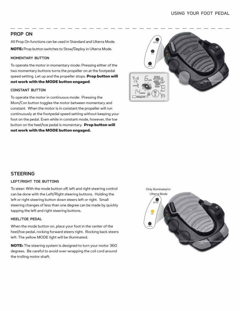
STEERINGLEFT/RIGHT TOE BUTTONS
To steer: With the mode button off , left and right steering control can be done with the Left/Right steering buttons. Holding the left or right steering button down steers left or right. Small steering changes of less than one degree can be made by quickly tapping the left and right steering buttons.
HEEL/TOE PEDAL
When the mode button on, place your foot in the center of the heel/toe pedal, rocking forward steers right. Rocking back steers left. The yellow MODE light will be illuminated.
NOTE: The steering system is designed to turn your motor 360 degrees. Be careful to avoid over-wrapping the coil cord around the trolling motor shaft.
Only illuminated in Ulterra Mode
AUTOPILOTSPOT-LOCK
MODE
CONSTANT
AUTOPILOTSPOT-LOCK
MODE
CONSTANT
PROP ONAll Prop On functions can be used in Standard and Ulterra Mode.
NOTE: Prop button switches to Stow/Deploy in Ulterra Mode.
MOMENTARY BUTTON
To operate the motor in momentary mode: Pressing either of the two momentary buttons turns the propeller on at the footpedal speed setting. Let up and the propeller stops. Prop button will
not work with the MODE button engaged.
CONSTANT BUTTON
To operate the motor in continuous mode: Pressing theMom/Con button toggles the motor between momentary and constant. When the motor is in constant the propeller will run continuously at the footpedal speed setting without keeping your foot on the pedal. Even while in constant mode, however, the toe button on the heel/toe pedal is momentary. Prop button will
not work with the MODE button engaged.
USING YOUR FOOT PEDAL
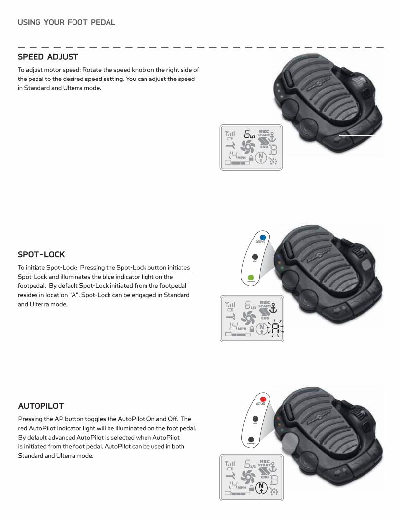
AUTOPILOTPressing the AP button toggles the AutoPilot On and Off . The red AutoPilot indicator light will be illuminated on the foot pedal. By default advanced AutoPilot is selected when AutoPilot is initiated from the foot pedal. AutoPilot can be used in both Standard and Ulterra mode.
AUTOPILOTSPOT-LOCK
MODE
CONSTANT
SPOT-LOCKTo initiate Spot-Lock: Pressing the Spot-Lock button initiates Spot-Lock and illuminates the blue indicator light on the footpedal. By default Spot-Lock initiated from the footpedal resides in location "A". Spot-Lock can be engaged in Standard and Ulterra mode.
AUTOPILOTSPOT-LOCK
MODE
CONSTANT
SPEED ADJUSTTo adjust motor speed: Rotate the speed knob on the right side of the pedal to the desired speed setting. You can adjust the speed in Standard and Ulterra mode.

ALTERNATIVE STOWING PROCEDURES
SYSTEM READY
POWERSTATUS
In the unlikely event Ulterra will not trim or stow, the following procedure will reset the motor and restore functionality:
1. Press and hold the POWER button located at the mounting base to turn power off (green LED light willturn off ).
2. Press the POWER button until the green LED lightilluminates.
3. Wait 3 seconds.
4. Press the POWER button 3 times within a 2 secondperiod.
5. Red and green LED lights will fl ash continuously andthe Ulterra will go through the following automated sequence:
• Motor will position itself into the proper orientation
• Motor will automatically trim up to the mounting base and trim down approximately 6 inches.
• The fl ashing red LED light will turn off , and the fl ashing green LED light will become solid green.
Ulterra is now reset and fully functional.
If Ulterra does not reset, repeat the procedure.
NOTE: If the lower unit of the motor is trimmed within 6 inches of the mounting base and the boat hull is obstructing the motor’s turning radius, manually turn the head of the motor so that the lower unit is perpendicular to the motor ramps prior to beginning this procedure.
In the unlikely event your remote becomes non-functioning, you can stow the Ulterra from the base of the motor by completing the following sequence:
1. Ensure that the motor is on.
2. Press and hold the POWER button located at the mounting base for10 seconds.
3. The red and green LEDs will fl ash alternately, and motor will beginstow process.
STOWING FROM THE ULTERRA MOTOR
TRIM/STOW RESET PROCEDURE
SYSTEM READY
POWERSTATUS
MANUAL STOW PROCEDURE
In the unlikely event that the motor will not stow from either the remote or foot pedal command, the following alternative stow methods should solve the issue:
1. Trim/Stow Reset Procedure (see “Alternate Stowing Methods” section)2. Stowing from the Motor (see “Alternate Stowing Methods” section)3. If your batteries lose power to the level that the motor will not stow, the motor will most likely stall at a 45 degree angle. If
this occurs, reengage power, deploy the motor, trim motor to its highest setting, and turn power off until batteries can be recharged. Once batteries are charged, attempt to stow motor again.
If all three alternative methods have been tried and the motor will still not stow, there is a method to manually stow the motor. However, ONCE THE MOTOR HAS BEEN MANUALLY STOWED, IT WILL BE NON-OPERATIONAL UNTIL IT IS MANUALLY RESET BY AN
AUTHORIZED SERVICE CENTER. If a manual stow must be done, follow the instructions below:
MANUAL STOW PROCEDURE
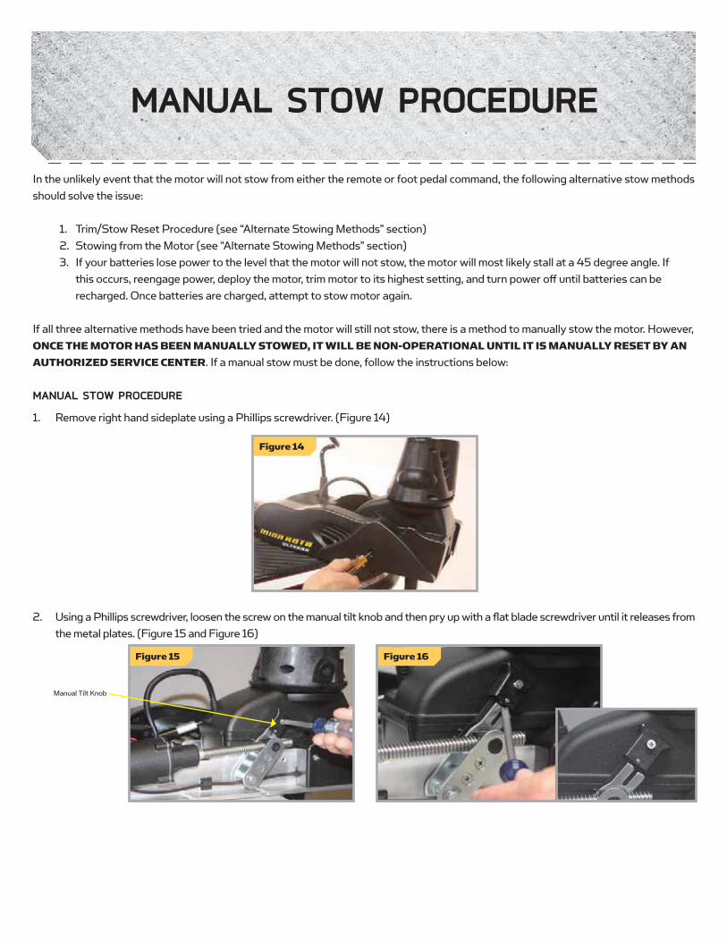
1. Remove right hand sideplate using a Phillips screwdriver. (Figure 14)
2. Using a Phillips screwdriver, loosen the screw on the manual tilt knob and then pry up with a fl at blade screwdriver until it releases from the metal plates. (Figure 15 and Figure 16)
Figure 14
Manual Tilt Knob
Figure 15 Figure 16

MANUAL STOW PROCEDURE
3. Pull manual trim handle out while lifting up on the trim housing until shaft and trim module can be pulled up by hand. (Figure 17)
4. While pulling up on the bracket to release the latch pin, rotate (Figure 18) and pull the lower unit onto the ramps. (Figures 19 & 20)
5. Secure lower unit onto the ramps using the provided emergency strap. The d-ring on the emergency strap can be hooked into thebase as shown (Figure 21). This feature is located on the left side of the motor as viewed from the boat interior. (Figure 22)
Figure 17
Trim Handle
Trim Housing
Figure 21 Figure 22
Figure 19
Figure 18
Figure 20

ADJUSTING THE LIFT BELTPeriodically slack may appear in the main lift belt, and it may occasionally require small adjustments to maintain belt tension. Using a 5/32” allen wrench turn the socket head cap screw, located on the bottom of the control head, clockwise (see Figure 23) until belt is fi nger tight and you can force fi nger under belt.
Figure 23
ADJUSTMENTS
SERVICE & MAINTENANCE
GREASING THE LATCH PINIn order for Ulterra to continue running at optimum performance, it is recommended that the latch pin be greased every season. To apply grease, partially deploy motor. Apply a small amount of marine grade grease to both sides of the latch pin as well as on the threaded acme shaft (Figure 24).
Figure 24
Apply grease to these areas periodically for optimum performance.
Latch pin
Threaded acme shaft
Steering Housing
Propeller
Slot End
Drive Pin
Prop NutWasher
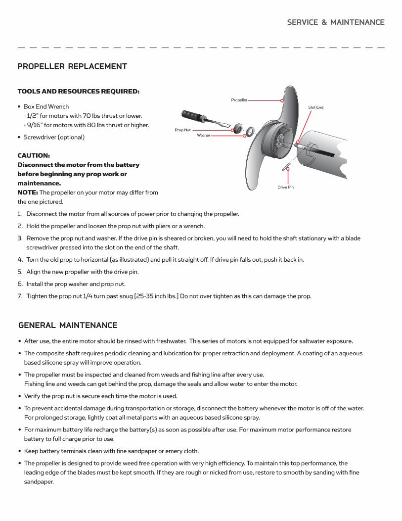
PROPELLER REPLACEMENT
TOOLS AND RESOURCES REQUIRED:
• Box End Wrench- 1/2” for motors with 70 lbs thrust or lower.- 9/16” for motors with 80 lbs thrust or higher.
• Screwdriver (optional)
CAUTION:
Disconnect the motor from the battery
before beginning any prop work or
maintenance.
NOTE: The propeller on your motor may diff er from the one pictured.
1. Disconnect the motor from all sources of power prior to changing the propeller.
2. Hold the propeller and loosen the prop nut with pliers or a wrench.
3. Remove the prop nut and washer. If the drive pin is sheared or broken, you will need to hold the shaft stationary with a bladescrewdriver pressed into the slot on the end of the shaft.
4. Turn the old prop to horizontal (as illustrated) and pull it straight off . If drive pin falls out, push it back in.
5. Align the new propeller with the drive pin.
6. Install the prop washer and prop nut.
7. Tighten the prop nut 1/4 turn past snug [25-35 inch lbs.] Do not over tighten as this can damage the prop.
GENERAL MAINTENANCE
• After use, the entire motor should be rinsed with freshwater. This series of motors is not equipped for saltwater exposure.
• The composite shaft requires periodic cleaning and lubrication for proper retraction and deployment. A coating of an aqueousbased silicone spray will improve operation.
• The propeller must be inspected and cleaned from weeds and fi shing line after every use. Fishing line and weeds can get behind the prop, damage the seals and allow water to enter the motor.
• Verify the prop nut is secure each time the motor is used.
• To prevent accidental damage during transportation or storage, disconnect the battery whenever the motor is off of the water.For prolonged storage, lightly coat all metal parts with an aqueous based silicone spray.
• For maximum battery life recharge the battery(s) as soon as possible after use. For maximum motor performance restorebattery to full charge prior to use.
• Keep battery terminals clean with fi ne sandpaper or emery cloth.
• The propeller is designed to provide weed free operation with very high effi ciency. To maintain this top performance, the leading edge of the blades must be kept smooth. If they are rough or nicked from use, restore to smooth by sanding with fi nesandpaper.
SERVICE & MAINTENANCE

ULTERRA
1. Motor fails to run or lacks power:
• Check battery connections for proper polarity.
• Are batteries charged?
• Make sure terminals and wires are clean and corrosion free. Use fi ne sandpaper or emery cloth to clean terminals.
• Check circuit protection devices.
• Check battery water level. Add water if needed.
2. Motor loses power after a short running time:
• Check battery charge. If low, restore to full charge, or replace.
3. You experience prop vibration during normal operation:
• Remove and rotate the prop 180°. See removal instructions in the Propeller Replacement Section. Replace prop if worn.
4. Experiencing interference with your fi shfi nder:
• You may, in some applications, experience interference in your depth fi nder display. We recommend that you use a seperate deepcycle marine battery for your trolling motor and that you power the depth fi nder from the starting/cranking battery.
5. Motor contacts an object while trimming causing a current limit (red status LED fl ashing):
• Reverse the direction of trimming to clear motor from obstruction.
6. Motor contacts an object while stowing causing current limit (red status LED fl ashing):
• Reverse the current cycle by pressing the stow/deploy button to clear from obstruction.
7. Motor fails to trim:
• Check main lift belt tension per the Adjustments section.
8. Motor fails to stow or deploy:
• Check for obstructions preventing the motor from deploying or stowing.
• Ensure that manual tilt knob is engaged. See the Emergency Stow Procedure section for details.
• Check charge state of trolling motor batteries. If trolling motor battery icon on remote is fl ashing, battery charge is toolow for operation.
9. Prop will not turn on:
• Ensure batteries are suffi ciently charged.
• For safety reasons there is a prop lock out region (approx. 15” from mounting base to lower unit centerline). Ensure that thelower unit is not in this region.
TROUBLESHOOTING

TROUBLESHOOTING
i-PILOT GENERAL TROUBLESHOOTINGProblem: The motor is making erratic steering corrections while in AutoPilot, Spot-Lock or Track to Start/End.
Solution: Be sure to keep all ferrous metallic objects away from the i-Pilot controller as they will have an impact on the built-in compass. Such objects include: anchors, metal framework, etc.
Problem: When a button on the remote is pressed the motor doesn’t always respond.
Solutions: Check if the low battery indicator is on. If so, replace the remote’s battery. Check for large obstructions between the remote and the motor.
Problem: I press a button on the remote and nothing happens.
Solution: Could be a dead battery in the remote. If the battery was just replaced, open the remote case and verify that all the internal components were properly reinstalled.
Solution: If is displayed, the keypad is locked. Press and hold for 3 seconds to unlock the keypad.
Problem: I press a button on the remote and all the icons come on for a few seconds then it shuts off .
Solutions: Verify that the motor is powered up. Go through the learn process for the remote (see page 17 for the procedure).
Problem: i-Pilot won’t let me turn on certain features like: Advanced AutoPilot, Record, Track to Start/End or
Spot-Lock.
Solution: Verify that the GPS Signal Strength icon on the LCD shows at least one bar. If there are no bars, i-Pilot will not allow these GPS-based features to be enabled.
Problem: The remote LCD backlighting will not come on.
Solution: Check if the low battery indicator icon is on. Backlighting is disabled when a low battery level is detected. Replace the battery.
Solution: The Backlight will not come on if the remote is not currently communicating with the i-Pilot Controller.
SPOT-LOCKProblem: The boat doesn’t seem to keep close enough to the recorded Spot-Lock location.
Solution: Verify the trolling motor batteries are suffi ciently charged.
Solution: Check for weeds on the prop.
Solution: In more extreme wind and current conditions, the boat will tend to stabilize a little ways down wind from the intended location. Relock the location the same distance upwind and expect that the boat will drift some in the downwind direction.
CRUISE CONTROLProblem: The GPS speed displayed on the remote is diff erent than what my other GPS system shows.
Solution: If you are using Cruise Control with Advanced AutoPilot or Track to Start/End, i-Pilot calculates the actual speed in the intended direction of travel which may diff er from your GPS reported speed.
Problem: Cruise Control isn’t holding the target speed close enough.
Solution: Verify the trolling motor batteries are suffi ciently charged.
TROUBLESHOOTING
AUTOPILOTProblem: When in Advanced AutoPilot in strong winds, there is quite a bit of back and forth movement in the
boat.
Solution: While Advanced AutoPilot will keep your boat on a true heading, it may be at the expense of the boat having to continuously move to get back on the correct course. In these extreme conditions you may be better off using AutoPilot and correcting for the wind manually.
Problem: I press and release the Advanced AutoPilot button and the system goes into AutoPilot instead of
Advanced AutoPilot.
Solution: If the GPS Signal Strength indicator shows no bars, then pressing and releasing the AutoPilot button will enable AutoPilot automatically instead of requiring that the button be held for two to three seconds like when GPS is present.
TRACK RECORD AND PLAYBACKProblem: While in Track to Start/End the propeller suddenly stopped.
Solution: Verify you did not accidentally enable another automatic feature such as AutoPilot or Spot-Lock. Solution: When the end (or start) of the track is achieved during playback, i-Pilot will automatically turn off the motor along with
canceling Track to Start/End.
Problem: While in Record mode, the recording suddenly stopped.
Solution: You may have reached the two mile limit for recording a track.

ULTERRAQ: Is there a trolling motor battery meter on Ulterra?
A: Yes. The motor battery meter is displayed on the i-Pilot or i-Pilot Link remote control LCD screen. Battery meter is displayed when prop is off .
Q: Which quick release brackets are compatible with Ulterra
A: The following quick release brackets can be used with UIterra: MKA-32, MKA-16-02, RTA 17 and RTA 21.
Q: Is there a manual Stow and Deploy procedure?
A: Yes. There is a manual method for stowing Ulterra. See the Emergency Stow Procedure section for instructions.
Q: When Ulterra is deployed, at what depth does the deploy stop?
A: Ulterra will always deploy to the most recent depth that was used.
Q: Are the Ulterra and Terrova foot pedals interchangeable?
A: No. The foot pedals are not interchangeable.
Q: If I engage Spot-Lock on the foot pedal, which Spot-Lock position on the remote is used?
A: i-Pilot: When Spot-Lock is activated from the foot pedal it will always utilize position “A” on the remote.A: i-Pilot Link: When Spot-Lock is enabled from the foot pedal, the user has the option of saving or discarding the Spot-Lock
loction. If saved, the next available Spot-Lock number will be utilized.
Q: What is the “Mode” button on the foot pedal?
A: The Ulterra foot pedal is dual function. When it is in “Ulterra” mode, the yellow LED light will be illuminated. In this state the foot pedal toe buttons can be used to auto stow and deploy the motor and control trim. When it is in “steering” mode, the yellow LED will be off . In this state the foot pedal toe buttons can be used to control steering and prop on/off . In either state, the heel/toe pad can be used to control steering.
Q: Is there a way to clean weeds from the lower unit?
A: Yes. During the process of stowing, the stow cycle can be stopped by pressing the stow/deploy button as the motor begins to tilt back. The lower unit is easily accessible at this point to clear weeds. A second button press of the stow/deploy cycle will re-deploy the motor to its previous position.
Q: Can I stow the motor with the prop in or out?
A: Yes, the motor can be confi gured to stow with either the prop in or out. Follow the procedure outlined in the Installation Mounting Options section.
FAQ

FAQ
i-PILOT Q: Does i-Pilot record the speed I am traveling when recording a track?
A: No. i-Pilot only records its location during track record. It is up to the user to set the desired speed manually or with Cruise Control.
Q: Why doesn’t my GPS Signal Strength icon always show all four bars?
A: GPS signal strength is impacted by many infl uences including: • i-Pilot controller having a clear view of the sky (especially to the southern sky),• Boat being located alongside a high bank• Your geographic location.
Q: Is i-Pilot compatible with CoPilot?
A: No. None of the components between the two systems are compatible with each other.
Q: Does the remote fl oat?
A: Yes.
Q: How long of a track can I record?
A: Each individual track location (A, B, C, D, E or F) can be up to two miles in length.
Q: Can I use multiple remotes with my i-Pilot?
A: Yes, you can use an unlimited number of remotes simultaneously. Remember to learn each new remote to the i-Pilot controller.
Q: Why does the LCD screen of the remote have dark blotches on it when I wear my sunglasses?
A: Polarized sunglasses can dramatically aff ect the way an LCD looks to the human eye.
Q: Can I control how fast i-Pilot takes me back to a Spot-Lock location when using Spot-Lock Recall?
A: No, Spot-Lock and Spot-Lock Recall are fully automatic functions that take full control of motor steering and speed.
Q: Where can I purchase additional remotes?
A: Your local Minn Kota retailer should carry additional remotes.
Q: If I turn off the remote, will i-Pilot continue to operate?
A: Yes. The i-Pilot Controller will continue in its current state of operation until the user makes a change either with the remote or foot pedal (Terrova only).
Q: Where are the six tracks and Spot-Lock locations stored?
A: In the i-Pilot Controller.
Q: Does i-Pilot help to keep the coil cord from wrapping around the motor shaft?
A: Yes and no. When in Spot-Lock, i-Pilot keeps track of how far it has rotated in either direction. If a new correction will cause the coil cord to wrap, it will rotate in the opposite direction in order to prevent the wrapping. In all other modes, it is up to the user to monitor the coil cord and to rotate the motor accordingly to avoid wrapping.
PARTS DIAGRAMPARTS DIAGRAM
24 Volt Motor
36 Volt Motor
86
87
8889
91
9092
9394
95
96
242
24380
79
78
96 71
72
73
5
74
75
64
65
66
67
68
69
70
50
179
244
61
34
20
3362
63
35
36
37
38
39
40
41
4231 30
28
27
26
32
24
47
177
109
5150
4950
51
48
5253
54
56
5557
58
59
50
117
249
118
118
246119
8711
120121
122123
124125
126
127
249
11250115
11351
112
110
111
109
108
107
62
63106
105
105
103104
101
100
97
98
99
149
148
150
171
151
152
153
151
152
154
155
11
156
157
158
160
159
18
170
169
168
167166165164163
162161
194 195 196197
199
200
198
201202
203204
205206207
208209
210 211180
211
212
223 210
217
215214213
235219
218
197
198
199221 201
203204 222 224 225 226222228
180229
230231 232
233
216
234
216
218219
220195194
102
116114
192
192
60
46
45
4443
241
147
29
28
26
27
25
24
23
2221
2
3
239
237240
186185
187
188
180
191190189
182175
174173
172
105
146145
183
184
181
12116
5
67
8
419
18
18
17
16
15
14
13
77
23885
84
83
76
245
178
1
247
248
176 63
105
145
235
131
130
129128
134135 136
137 138140
141142
143 144
133132
139
19382
81250
251
251
174
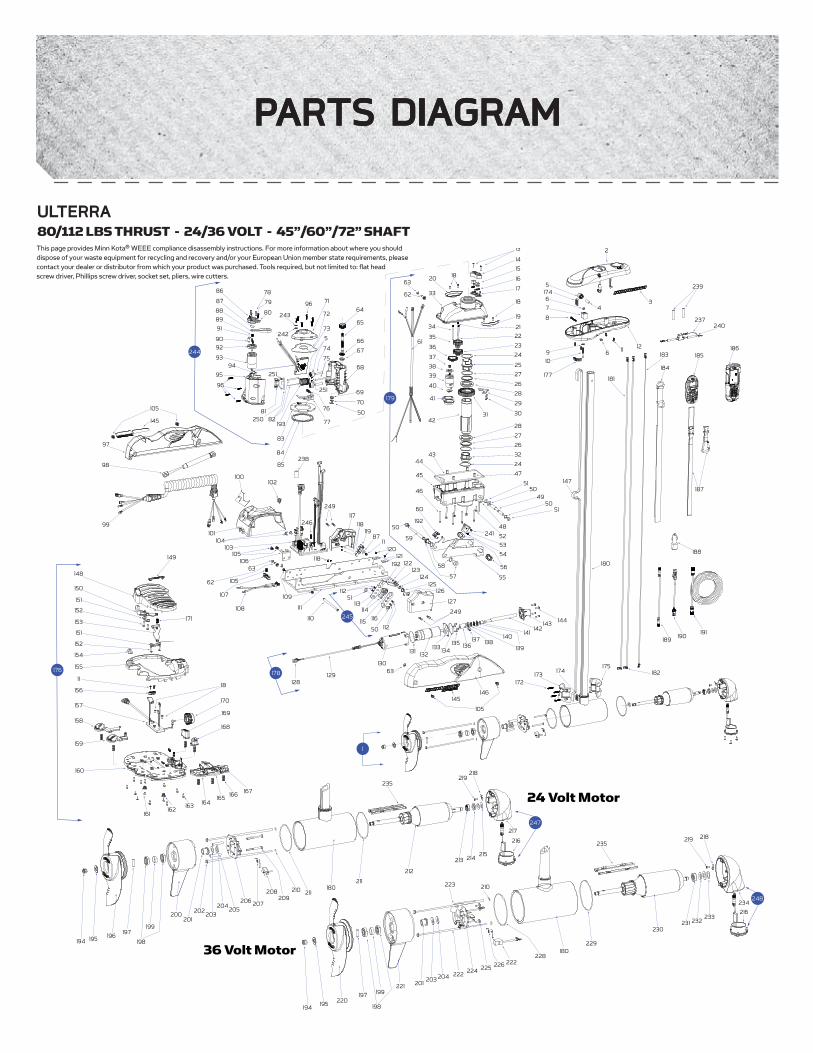
This page provides Minn Kota® WEEE compliance disassembly instructions. For more information about where you should dispose of your waste equipment for recycling and recovery and/or your European Union member state requirements, please contact your dealer or distributor from which your product was purchased. Tools required, but not limited to: fl at head screw driver, Phillips screw driver, socket set, pliers, wire cutters.
ULTERRA 80/112 LBS THRUST - 24/36 VOLT - 45”/60”/72” SHAFT

ITEM QTY PART NUMBER DESCRIPTION
1 1 2777016 24 V MOTOR 45" FW
1 2777015 24V MOTOR 60" FW
1 2777086 36V MOTOR 45" FW
1 2777085 36V MOTOR 60" FW
1 2777087 36V MOTOR 72" FW
2 1 2990206 HEAD ASSY, FW, IPILOT 1.5
1 2990208 HEAD ASSY, FW, IPILOT LINK
3 2 2205511 DECAL, CONTROL BOX SIDE
4 1 2202635 PIN-DOWEL, 1/4" OD SS
5 3 * PULLEY, BELT, TOP
6 2 2333101 NUT-HEX #10-24
7 1 2202800 BLOCK, BELT
8 1 2383407 SCREW-#10-24 X 2" PPH ZINC
9 1 2201721 WASHER, #10 SAE, SS
10 1 2203411 SCREW-#10-24, SHCS, SS
11 6 2372100 SCREW, #8-18 X 5/8 THD
12 1 2202506 CONTROL BOX BOTTOM
13 2 2203406 SCREW, #6-32 X 0.75 PPH, SS
14 1 * BLOCK-BRUSH, SLIPRING
15 2 * BRUSH SHUNT ASSY
16 4 * SPRING COMPRESSION, BRUSH
17 1 * INSULATOR, BLOCK-BRUSH
18 6 2332103 SCREW-#6-20 X 3/8 THD, SS
19 1 2205905 RIGHT STEERING ADAPTER
20 1 2205900 LEFT STEERING ADAPTER
21 1 2302615 SHAFT-GEAR, INTERMED. CLUSTER
22 1 2302620 SHAFT-GEAR, THIRD CLUSTER
23 1 2302250 GEAR & PINION, DR. HSG, STAGE 3
24 2 2321704 WASHER-THRUST, STEERING
25 1 2201510 COLLAR-DRIVE, OUTPUT TUBE
26 2 2324608 O-RING, 224, PD PRO STEERING HOUSING
27 2 2321720 SHIM, O-RING
28 2 2327308 BEARING-BALL, SEALED, 6809-2RS
29 1 2201920 BRACKET-SENSOR, STEERING HSG
30 2 2303412 SCREW-#6-20 X 5/8 SELF TAP
31 1 2772200 GEAR-OUTPUT
32 1 2321510 COLLAR-DRIVE, BOTTOM
33 1 * BLACK STEERING HSG COVER
34 1 * SHAFT-GEAR, FIRST CLUSTER
35 1 2302255 GEAR & PINION, STAGE 4
36 1 2302245 GEAR & PINION, STAGE 2
37 1 2302240 GEAR & PINION, STAGE 1
38 1 2300265 CAP-MOTOR, PLASTIC
39 1 * MOTOR-STEERING PD/AP 36V
1 * MOTOR-STEERING PD/AP 24V
40 1 2300260 CAP-SPACER, PLASTIC
41 1 2328610 CRADLE- MOTOR
42 1 2322030 TUBE-OUTPUT, MACHINED
43 1 2324604 O-RING, CASE SEAL
44 1 2308601 BREATHER FILTER, DR. HSG
45 1 * STEERING HSG, BTTM, BLK
46 7 2323408 SCREW-#8-32 X 2.0 SHCS SS
47 4 * PIN-ROLL 5/16" X 1/2"
48 2 2322702 SPRING, LATCH PIN SS
49 1 2202626 PIN-LATCH
50 5 * E-RING 3/8 DIA. SHAFT
51 3 2321702 WASHER-FLAT .375 NYLON
52 1 2323410 SCREW-#8-32 X .75 SHCS SS
ITEM QTY PART NUMBER DESCRIPTION
53 1 2770100 KNOB, TILT RELEASE
54 1 * SCREW-#6-32 X .625" SET SS
55 1 2201911 BRACKET, TILT, ZP
56 2 2207305 BUSHING, LATCH PIN
57 2 2207310 BUSHING, STRG HSG PIVOT
58 2 2201730 WASHER-FLAT, .56 ID NYLON
59 1 2202601 PIN-PIVOT, DRIVE HOUSING, SS
60 1 2778601 HOLDER-MAGNET
61 1 * LEADWIRE, STEERING MTR, 8 COND.
62 2 2202902 STANDOFF, OIL DAMPENER
63 2 2263006 E-CLIP, 5/16
64 1 * PULLEY, TRIM JACKSHAFT
65 1 * WORM SHAFT ASSY W/ PULLEY
66 1 * BEARING-THRUST, NEEDLE
67 1 * BUSHING, TRIM, TOP
68 1 * HOUSING-TRIM, GEAR SIDE
69 1 * BUSHING, TRIM, BOTTOM
70 1 * WASHER-THRUST, 3/8"
71 1 2206410 COVER, TRIM HOUSING
72 1 2204601 O-RING, TRIM HOUSING
73 1 2204600 O-RING, TRIM HSG COVER
74 2 * PIN, BELT PULLEY
75 1 * PIN, 2"X1/4"
76 1 * SPRING, 5/16" OD, SS
77 1 * HANDLE, TRIM HSG RELS, ZP
78 3 2053422 SCREW-M3-.5 X 10 PPH, ZP
79 3 2051710 LOCKWASHER-SPLIT, 3MM, ZP
80 1 * PLATE, MOTOR
81 1 * BLOCK, TUBE DRIVE
82 2 * PIN-DOWEL, 1/8"
83 1 * CARRIER, SLIPRING CONTACTS
84 1 * CONTACT, SLIPRING SMALL
85 1 * CONTACT, SLIPRING LARGE
86 1 2053420 SCREW-SET-#8-32 X 1/4" SS
87 1 * WASHER-#6, .625 OD
88 1 2200810 BELT-TRIM
89 1 * PULLEY, LIFT MOTOR, MACHINED
90 1 2058411 TENSIONER-BELT
91 2 * SCREW-M4 X 10 PFH, ZP
92 1 * PLATE-ADAPTER, LIFT MOTOR
93 1 * MOTOR, TRIM
94 1 * BOARD ASSY, WIRELESS TRIM
1 * BOARD ASSY, WIRELESS TRIM (EUROPE)
95 1 * HOUSING-TRIM, MOTOR SIDE
96 11 3393481 SCREW, #10X.75 HI-LO, SS, PPH
97 1 2203905 SIDEPLATE, LEFT
98 1 2208800 DAMPER, HYBRID, 80#
1 2208802 DAMPER, HYBRID, 112#
99 1 2991272 COIL CORD ASSY 54/60" U. SONAR
1 2991276 COIL CORD 72"
100 1 2205600 DECAL, B. METER/CON/PWR FW, BLK
101 1 2206510 HOUSING-CONTROL, BLACK
102 1 2202910 STRAIN RLF, HEYCO SR 6N3-4
103 1 2774080 MAIN CONTROL BOARD, 24V, 60", N AMERICA
2774081 MAIN CONTROL BOARD, 24V, 45", N AMERICA
2774082 MAIN CONTROL BOARD, 36V, 60", N AMERICA
2774083 MAIN CONTROL BOARD, 36V, 45", N AMERICA
*Item is part of an assembly and is listed for reference only. Item cannot be ordered seperately. Refer to “Service Kits” section for kit part number.
ULTERRA 80/112 LBS THRUST - 24/36 VOLT - 45”/60”/72” SHAFT
†This is a service kit and includes multiple parts. Refer to “Service Kits” section for complete part listing.
PARTS LIST

ITEM QTY PART NUMBER DESCRIPTION
2774084 MAIN CONTROL BOARD, 24V, 60", EUROPE
2774085 MAIN CONTROL BOARD, 24V, 45", EUROPE
2774086 MAIN CONTROL BOARD, 36V, 60", EUROPE
2774087 MAIN CONTROL BOARD, 36V, 45", EUROPE
2774091 MAIN CONTROL BOARD, 36V, 72", N AMERICA
104 2 2323406 SCREW-#10-24 X .50 CRPH SS
105 7 2323404 SCREW-1/4-20 X 1/2" T-L ZP
106 1 2200821 CLIP-CORD, ZP
107 1 2321310 STRAIN RELIEF
108 1 2090651 LEADWIRE, 10 GA
109 2 2383447 SCREW-#10-32 X 3/8" PPH SS
110 1 2202606 PIN, ACTUATOR, ZP
111 1 2201901 BASE, MACHINED, FW
112† 4 2203410 SCREW #10-32 X .5"
113† 1 2204201 ARM-LIFT, INNER, ZP
114† 2 2202901 STANDOFF, LIFT ARM
115† 1 2203100 NUT, TILT MOTOR
116† 1 2204206 ARM-LIFT, OUTER, ZP
117 1 2203916 RAMP-MOTOR, LEFT 80#
1 2203915 RAMP-MOTOR, LEFT 112#
118 10 2373440 SCREW-#4-24 X 1/4 PHCR SS TY B
119 1 2773700 PLUNGER, RAMP
120 2 2203420 SCREW #10-24 X 5/16 PFH
121 2 2205105 PAD, STOP
122 1 2262632 PIN-SPRING 1/4" X 5/8" SS
123 1 2777900 CAM, PIN SENSOR
124 1 2201702 SPACER, PIN SENSOR
125 1 2042711 SPRING-TORSION, SS
126 1 9280710 HDW SCR 1/4 - 20 X 7/8 TRUSS PHIL
127 1 2203911 RAMP-MOTOR, RIGHT, 80#
2203910 RAMP-MOTOR, RIGHT, 112#
128 1 * HOUSING, CONNECTOR WPJ
129 1 * LEADWIRE, TILT MOTOR
130 1 * COVER, TILT ACTUATOR
131 1 * O-RING, TILT, LARGE
132 1 * MOTOR, STOW/DEPLOY
133 1 * MOUNTING PLATE, TILT MOTOR
134 1 * O-RING, TILT, SMALL
135 4 * SCREW-M4 X 8, SS
136 1 * COUPLER, STW/DPLY ACTUATOR
137 1 * SPRING PIN, 5MM X 20MM
138 1 * SEAL, TILT MOTOR
139 2 * WASHER-THRUST, TILT MOTOR
140 1 * BEARING-THRUST, TILT MOTOR
141 1 * SPACER, SHAFT
142 1 * SHAFT, STOW/DEPLOY, SS
143 1 * COVER-NOSE, TILT ACTUATOR
144 4 * SCREW-#8-18 X 5/8" PPH
145 2 2205510 DECAL, SIDEPLATE, FW
146 1 2203900 SIDEPLATE, RIGHT
147 1 2770816 BELT-LIFT 45”
2770818 BELT-LIFT 60”
2770819 BELT-LIFT 72”
148 1 2324400 PEDAL, HEEL/TOE FOOT PEDAL
149 1 2326710 PLUG, FOOT PEDAL
150 1 2323710 BUTTON, MOM LEFT, FT PEDAL
151 2 2321300 CLAMP-LEFT, FT PEDAL
152 4 2223430 SCREW-#8 X 3/4 PPH
153 1 2328600 FLEX FINGER, FOOT PEDAL
154 1 2205605 DECAL, 3 INDICATORS
155 1 * COVER, HEEL TOE FOOT PEDAL
156 1 2322900 STRAIN RELIEF, FOOT PEDAL
157 1 * PCB ASSY, FOOT PEDAL
158 1 * BUTTON, AP, FT PEDAL
ITEM QTY PART NUMBER DESCRIPTION
159 1 * BUTTON, MOM/CON, FT PEDAL
160 1 * BASE PLATE
161 2 2323420 SCREW, #8-18 3/8 PFH SS
162 2 2322706 SPRING-BARREL SS
163 11 2301310 SCREW, #8-18 X 1/2" SS
164 1 * BUTTON, LFT STR W/ TRIM UP ARROW
165 1 * BUTTON, MOMENTARY/STOW-DEPLOY
166 7 * SPRING, LARGE SHORT SS
167 1 * BUTTON, RGT STR W/ TRIM UP ARROW
168 1 * BUTTON, SPOT LOCK
169 1 * BUTTON, MODE
170 1 * KNOB-SPEED, FOOT PEDAL
171 1 2322714 SPRING, MOM ASSIST SS
172 4 3393480 SCREW-#10 X 1.0" PPH HI-LO SS
173 1 2201505 COLLAR, BELT CLAMP
174 2 2200800 BELT-RACK, LOWER
175 1 2201500 COLLAR, CLAMP
176 1 2994740 FOOT PEDAL ASSY
177 1 2224700 PLUG INSERT (IPILOT)
2224704 PLUG INSERT (IPILOT LINK)
178† 1 2997813 TILT MOTOR ASSY
179† 1 2776501 STEERING HOUSING ASSY 24 V
1 2776503 STEERING HOUSING ASSY 36 V
180 1 2777098 CTR HSG ASSY, CB, 80#, FW, W/TUBE, 45"
1 2777099 CTR HSG ASSY, CB, 80#, FW, W/TUBE, 60"
1 2777248 CTR HSG ASSY, CB, 112#, FW, W/TUBE, 45"
1 2777249 CTR HSG ASSY, CB, 112#, FW, W/TUBE, 60"
1 2777250 CTR HSG ASSY, CB, 112#, FW, W/TUBE, 72"
181 1 640-118 MOTOR WIRE, RED, 80#, 45"
1 640-132 MOTOR WIRE, RED, 112#, 45"
1 640-126 MOTOR WIRE, RED, 80#, 60"
1 640-135 MOTOR WIRE, RED, 112#, 60"
1 640-149 MOTOR WIRE, RED, 112#, 72"
182 1 640-027 MOTOR WIRE, BLACK, 80#, 45"
1 640-017 MOTOR WIRE, BLACK, 112#, 45"
1 640-022 MOTOR WIRE, BLACK, 80#, 60"
1 640-045 MOTOR WIRE, BLACK, 112#, 60"
1 640-049 MOTOR WIRE, BLACK, 112#, 72"
183 1 640-315 BONDING WIRE, BROWN, US2.0, 45"
1 640-316 BONDING WIRE, BROWN, US2.0, 60"
1 640-317 BONDING WIRE, BROWN, US2.0, 72"
184 1 2203800 STRAP, EMERGENCY
185 1 2994171 REMOTE ASSY, IPILOT 1.5
186 1 2994180 REMOTE ASSY, IPILOT LINK *LINK ONLY*
187 1 2370817 LANYARD, REMOTE W/ CARABEENER
188 1 2375901 ADAPTER, USB DC POWER *LINK ONLY*
189 1 2211415 CABLE-EXTENSION, PD/AP 110"
190 1 2373241 CABLE, USB REMOTE CHARGER *LINK ONLY*
191 1 490389-1 CABLE, ETHERNET, 30' * LINK ONLY*
192 9 * .187 X .125 MAGNET
193 1 * GEAR/PULLEY-WORM CLUSTER ASSY
194 1 2093101 NUT-PROP, NYLOCK, SS
195 1 2091701 WASHER-PROP
196 1 2331160 PROP-WW2, 80#
197 1 2262658 PIN-DRIVE 1" X 3/16" SS
198 2 880-025 SEAL
199 1 725-095 PAPER TUBE, SEAL
200 1 92-300-170 BRUSH END HSG, 80#
201 1 144-017 BEARING, FLANGE
202 2 830-095 THRU BOLT 12-24
203 1 990-052 WASHER, NYLATRON
204 1 990-051 WASHER-STEEL THRUST
205 2 973-025 SPACER, BRUSHPLATE
206 1 9-738-015 BRUSH PLATE ASSY, 4"
*Item is part of an assembly and is listed for reference only. Item cannot be ordered seperately. Refer to “Service Kits” section for kit part number.†This is a service kit and includes multiple parts. Refer to “Service Kits” section for complete part listing.
ULTERRA 80/112 LBS THRUST - 24/36 VOLT - 45”/60”/72” SHAFT
PARTS LIST

DESCRIPTION KIT ITEM NO. PART NO. ITEM NUMBER INCLUDED / QUANTITY
TILT MOTOR ASSY 178 2997813128 (1), 129 (1), 130 (1), 131 (1), 132 (1), 133 (1), 134 (1), 135 (1), 136 (1), 137 (1), 138 (1), 139 (1), 140 (1), 141 (1), 142 (1), 143 (1), 144 (1)
OUTPUT GEAR W/ MAGNETS 2772200 31 (1), 192 (4)
STEERING HOUSING ASSY, 24V 179 2776501
13 (2), 14 (1), 15 (1), 16 (2), 17 (1), 18 (4), 19 (1), 20 (1), 21 (1), 22 (1), 23 (1), 24 (2), 25 (1), 26 (2), 27 (2), 28 (2), 29 (1), 30 (2), 31 (1), 32 (1), 33 (1), 34 (1), 35 (1), 36 (1), 37 (1), 38 (1), 39 (1), 40 (1), 41 (1), 42 (1), 43 (1), 44 (1), 45 (1), 46 (7), 47 (4), 48 (1), 49 (1), 50 (3), 51 (2), 52 (1), 53 (1), 54 (1), 55 (1), 56 (2), 57 (2), 58 (2), 59 (1), 61 (1), 62 (1), 63 (1), 192 (1), 241 (1)
STEERING HOUSING ASSY, 36V 179 2776503
13 (2), 14 (1), 15 (1), 16 (2), 17 (1), 18 (4), 19 (1), 20 (1), 21 (1), 22 (1), 23 (1), 24 (2), 25 (1), 26 (2), 27 (2), 28 (2), 29 (1), 30 (2), 31 (1), 32 (1), 33 (1), 34 (1), 35 (1), 36 (1), 37 (1), 38 (1), 39 (1), 40 (1), 41 (1), 42 (1), 43 (1), 44 (1), 45 (1), 46 (7), 47 (4), 48 (1), 49 (1), 50 (3), 51 (2), 52 (1), 53 (1), 54 (1), 55 (1), 56 (2), 57 (2), 58 (2), 59 (1), 61 (1), 62 (1), 63 (1), 192 (1), 241 (1)
CAM W/ MAGNET AND SPRING PIN 2777900 122 (1), 123 (1),
RELEASE KNOB W/ SCREW 2770100 53 (1), 54 (1), 241 (1)
SENSOR WIRE W/ BUTT CONNECTORS 2880350
MOUNTING BAG 2994917
TRIM HOUSING ASSEMBLY - 45” 244 29978075 (2), 50 (1), 64 (1), 65 (1), 66 (1), 67 (1), 68 (1), 69 (1), 70 (1), 71 (1), 72 (1), 73 (1), 74 (2), 75 (1), 76 (1), 77 (1), 78 (1), 79 (1), 80 (1), 81 (1), 82 (1), 83 (1), 84 (1), 85 (1), 86 (1), 87 (1), 88 (1), 89 (1), 90(1), 91 (1), 92 (1), 93 (1), 94 (1), 95 (1), 96 (10), 193 (1), 242 (1), 243 (1) , 250 (1), 251 (4)
TRIM HOUSING ASSEMBLY - 60” 244 29978035 (2), 50 (1), 64 (1), 65 (1), 66 (1), 67 (1), 68 (1), 69 (1), 70 (1), 71 (1), 72 (1), 73 (1), 74 (2), 75 (1), 76 (1), 77 (1), 78 (1), 79 (1), 80 (1), 81 (1), 82 (1), 83 (1), 84 (1), 85 (1), 86 (1), 87 (1), 88 (1), 89 (1), 90(1), 91 (1), 92 (1), 93 (1), 94 (1), 95 (1), 96 (10), 193 (1), 242 (1), 243 (1) , 250 (1), 251 (4)
TRIM HOUSING ASSEMBLY - 72” 244 29978205 (2), 50 (1), 64 (1), 65 (1), 66 (1), 67 (1), 68 (1), 69 (1), 70 (1), 71 (1), 72 (1), 73 (1), 74 (2), 75 (1), 76 (1), 77 (1), 78 (1), 79 (1), 80 (1), 81 (1), 82 (1), 83 (1), 84 (1), 85 (1), 86 (1), 87 (1), 88 (1), 89 (1), 90(1), 91 (1), 92 (1), 93 (1), 94 (1), 95 (1), 96 (10), 193 (1), 242 (1), 243 (1) , 250 (1), 251 (4)
TRIM HOUSING ASSEMBLY - 45” (EUROPE) 244 29978275 (2), 50 (1), 64 (1), 65 (1), 66 (1), 67 (1), 68 (1), 69 (1), 70 (1), 71 (1), 72 (1), 73 (1), 74 (2), 75 (1), 76 (1), 77 (1), 78 (1), 79 (1), 80 (1), 81 (1), 82 (1), 83 (1), 84 (1), 85 (1), 86 (1), 87 (1), 88 (1), 89 (1), 90(1), 91 (1), 92 (1), 93 (1), 94 (1), 95 (1), 96 (10), 193 (1), 242 (1), 243 (1) , 250 (1), 251 (4)
TRIM HOUSING ASSEMBLY - 60" (EUROPE) 244 29978235 (2), 50 (1), 64 (1), 65 (1), 66 (1), 67 (1), 68 (1), 69 (1), 70 (1), 71 (1), 72 (1), 73 (1), 74 (2), 75 (1), 76 (1), 77 (1), 78 (1), 79 (1), 80 (1), 81 (1), 82 (1), 83 (1), 84 (1), 85 (1), 86 (1), 87 (1), 88 (1), 89 (1), 90(1), 91 (1), 92 (1), 93 (1), 94 (1), 95 (1), 96 (10), 193 (1), 242 (1), 243 (1), 250 (1), 251 (4)
TILT BRACKET ASSY 245 2774201 50 (1), 51 (1), 112 (4), 113 (1), 114 (2), 115 (1), 116 (1)
ASSEMBLY 80#, 45" 247 9421-287 216 (1), 217 (1)ASSEMBLY 80#, 60" 247 9421-290 216 (1), 217 (1)
ASSEMBLY 112#, 45" 248 9421-244 234 (1), 216 (1)
ASSEMBLY 112#, 60" 248 9421-246 234 (1), 216 (1)
ASSEMBLY 112#, 72" 248 9421-247 234 (1), 216 (1)
SERVICE KITS & ASSEMBLIES
ITEM QTY PART NUMBER DESCRIPTION
207 2 975-041 SPRING-TORSION
208 2 186-094 BRUSH 4"
209 2 830-027 SCREW-BRUSH PLATE 10-32
210 2 701-009 O-RING, THRU BOLTS
211 2 701-043 O-RING, END HOUSINGS
212 1 2-100-214 ARMATURE ASSY
213 1 140-010 BEARING - BALL
214 1 990-045 SPACER, THRUST
215 2 992-010 WASHER, SPRING BELLEVILLE
216 1 * TRANSDUCER ASSY US 2.5
217 1 * PLAIN END HOUSING, ASSY
218 1 230-038 CABLE CLAMP, STEEL
219 1 2302104 SCREW-#6 X 3/8
220 1 2341160 PROP-WW2, 112#
221 1 92-300-155 BRUSH END HSG, 112#
222 2 830-094 THRU BOLT 12-24
223 1 2307312 BEAD-FERRITE
224 1 9-738-011 BRUSH PLATE ASSY, 4.5"
225 2 2053410 SCREW-BRUSH PLATE, 10-32
226 2 975-045 SPRING-TORSION
227 2 188-095 BRUSH, 4.5" LU
228 1 701-107 O-RING, BRUSH END
229 1 701-098 O-RING, PLAIN END
230 1 2-100-245 ARMATURE ASSY
231 1 140-014 BEARING - BALL
232 2 992-011 WASHER, SPRING BELLEVILLE
ITEM QTY PART NUMBER DESCRIPTION
233 1 990-011 WASHER, SHIM
234 1 * PLAIN END HOUSING, ASSY
235 1 582-013 CLIP, RETAINING SHORT
236 1 582-016 CLIP-RETAINING, SONAR
237 1 2218200 FUSE HOLDER ASSY
238 1 2307313 FERRITE BEAD
239 2 2065400 WIRE INSULATOR-LGE 1-3/4,BLUE
240 2 2375400 SHRINK TUBE-1/4 OD X 1-3/4
241 1 2203407 SCREW, #6-32 X .5
242 6 3391732 SEALING WASHER
243 6 3394602 FLAT WASHER #8
244† 1 2997807 TRIM HOUSING ASSEMBLY - 45”
1 2997803 TRIM HOUSING ASSEMBLY - 60”
1 2997820 TRIM HOUSING ASSEMBLY - 72”
1 2997827 TRIM HOUSING ASSEMBLY - 45” (EUROPE)
1 2997823 TRIM HOUSING ASSEMBLY - 60” (EUROPE)
245† 1 2774201 TILT BRACKET ASSEMBLY
246 1 2373487 SCREW-#8-32 X 3/4
247† 1 9421-287 ASSEMBLY 80#, 45"
1 9421-290 ASSEMBLY 80#, 60"
248† 1 9421-244 ASSEMBLY 112#, 45"
1 9421-246 ASSEMBLY 112#, 60"
1 9421-247 ASSEMBLY 112#, 72"
249 4 2263453 SCREW, 1/4-20x1" SHCS S/S
250 1 * DRIVE BLOCK BRACKET
251 4 * SCREW-#4-24 X 1/4" PHCR SS
*Item is part of an assembly and is listed for reference only. Item cannot be ordered seperately. Refer to “Service Kits” section for kit part number.†This assembly includes multiple parts. Refer to “Service Kits” section for complete part listing.
ULTERRA 80/112 LBS THRUST - 24/36 VOLT - 45”/60”/72” SHAFT
PARTS LIST

ENVIRONMENTAL COMPLIANCE STATEMENT:
It is the intention of JOME to be a responsible corporate citizen, operating in compliance with known and applicable environmental regulations, and a good neighbor in the communities where we make or sell our products.
WEEE DIRECTIVE:
EU Directive 2002/96/EC “Waste of Electrical and Electronic Equipment Directive (WEEE)” impacts most distributors, sellers, and manufacturers of consumer electronics in the European Union. The WEEE Directive requires the producer of consumer electronics to take responsibility for the management of waste from their products to achieve environmentally responsible disposal during the product life cycle.WEEE compliance may not be required in your location for electrical & electronic equipment (EEE), nor may it be required for EEE designed and intended as fi xed or temporary installation in transportation vehicles such as automobiles, aircraft, and boats. In some European Union member states, these vehicles are considered outside of the scope of the Directive, and EEE for those applications can be considered excluded from the WEEE Directive requirement.
This symbol (WEEE wheelie bin) on product indicates the product must not be disposed of with other household refuse. It must be disposed of and collected for recycling and recovery of waste EEE. Johnson Outdoors Inc. will mark all EEE products in accordance with the WEEE Directive. It is our goal to comply in the collection, treatment, recovery, and environmentally sound disposal of those products; however, these requirement do vary within European Union member states. For more information about where you should dispose of your waste equipment for recycling and recovery and/or your European Union member state requirements, please contact your dealer or distributor from which your product was purchased.
DISPOSAL:
Minn Kota motors are not subject to the disposal regulations EAG-VO (electric devices directive) that implements the WEEE directive. Nevertheless never dispose of your Minn Kota motor in a garbage bin but at the proper place of collection of your local town council.
Never dispose of battery in a garbage bin. Comply with the disposal directions of the manufacturer or his representative and dispose of them at the proper place of collection of your local town council.
WARNING: This product contains chemicals known to the State of California to cause cancer and birth defects
or other reproductive harm.
COMPLIANCE STATEMENTSCOMPLIANCE STATEMENTS

COMPLIANCE STATEMENTS
FCC COMPLIANCEThis device complies with Part 15 of the FCC rules.
Operation is subject to the following two conditions:
1. This device may not cause harmful interference.
2. This device must accept any interference that may be received, including interference that may cause undesired operation.
Changes or modifi cations not expressly approved by Johnson Outdoors Marine Electronics, Inc. could void the user’s authority to operate this equipment.
This product meets the applicable Industry Canada technical specifi cations. Operation is subject to the following two conditions: (1) this device may not cause interference, and (2) this device must accept any interference, including interference that may cause undesired operation of the device.
Note: This equipment has been tested and found to comply with the limits for a Class B digital device, pursuant to part 15 of the FCC Rules. These limits are designed to provide reasonable protection against harmful interference in a residential installation. This equipment generates, uses and can radiate radio frequency energy and, if not installed and used in accordance with the instructions, may cause harmful interference to radio communications. However, there is no guarantee that interference will not occur in a particular installation. If this equipment does cause harmful interference to radio or television reception, which can be
determined by turning the equipment off and on, the user is encouraged to try to correct the interference by one or
more of the following measures:
• Reorient or relocate the receiving antenna.
• Increase the separation between the equipment and receiver.
• Connect the equipment into an outlet on a circuit diff erent from that to which the receiver is connected.
• Consult the dealer or an experienced radio/TV technician for help.
TRANSMITTER MODEL: 2990206
• IC: 4397A-ULTERRAIP15
• FCC ID: T62-ULTERRAIP15
TRANSMITTER MODEL: 2990208
• IC: 4397A-ULTERRA20
• FCC ID: T62-ULTERRA20

• 60-Amp Circuit Breaker
• Mounting Brackets
• Stabilizer Kits
• Extension Handles
• Battery Connectors
• Battery Boxes
• Quick Connect Plugs
RECOMMENDED ACCESSORIES
ON-BOARD & PORTABLE BATTERY CHARGERSStop buying new batteries and start taking care of the ones you’ve got. Many chargers can actually damage your battery over time – creating shorter run times and shorter overall life. Digitally controlled Minn Kota chargers are designed to provide the fastest charge that protect and extend battery life.
TALON SHALLOW WATER ANCHORTalon deploys faster, holds stronger and runs quieter than any other shallow water anchor. Available in depths up to 12’ and bold color options including camo, it boasts an arsenal of features and innovations that no other anchor can touch:
MINN KOTA ACCESSORIESWe offer a wide variety of trolling motor accessories, including:
MK210DMK345PC MK110P
• Vertical, Multi-Stage Deployment
• User-Selectable Anchoring Modes
• 2x Anchoring Force
• Fast Deploy
• Auto Up/Down
• Triple Debris Shields
• Built-In Wave Absorption
• Noise Dissipation
• Versatile Adjustments