ultimate kickoff meeting march 19, 2021
TRANSCRIPT
SELECTIVE THERMAL EMISSION COATINGSFOR IMPROVED TURBINE PERFORMANCE
ULTIMATE Kickoff MeetingMarch 19, 2021
Dr. B. Peter McGrail, Pacific Northwest National LabDr. Molly M. O’Connor, Praxair Surface TechnologiesDr. Ognjen Ilic, University of Minnesota

Motivation & Goals of the Project
1
▸Advance the design of TBCs to transform their radiative heat transfer properties
– Shift broadband optical emissions in the visible and IR wavelengths into a narrowmid-IR band (4 to 4.5 µm wavelength)
– Energy radiated in this band is absorbed by CO2 in the turbine exhaust within 4 cm of the source
▸Enhancing radiative heat transfer to the exhaust has three key benefits
– Reduced heat transfer and losses to the blade coolant
– Gain in power or thrust output from the turbine
– Larger performance gain at higher turbine operating temperatures to be achieved by the ULTIMATE program
Selective Thermal Emission and Radiation in Annuli (STERADIAN)

Technical Approach & Innovations of the Project
▸ Utilize principles of photonic metamaterial optics to design selective thermal emitter coatings
– Sub-wavelength structures with contrasting index of refraction and dielectric constants
– Induces excitations at the targeted wavelength while suppressing out-of-band emissions
▸ Two primary structural motifs will be investigated– Layered thin films– Photonic crystals
2
Wavelength (µm)
0 1 2 3 4 5
Spectr
al R
adia
nce (
kW
m-2
µm
-1)
0
5
10
15
20
25
30
1000K 1500K 2000K 2500K
CO2 Absorption Band
Normal broadband radiation has <5% of radiated power in the band where absorption by CO2 in the exhaust occurs
ULTIMATETBC Substrate
STERADIANSEC
Emis
sivi
ty
Wavelength (µm)
E-field magnitude

Technical Work Plan‣ Coating Design
– Leverage current STERADIAN1 designs for heat exchangers
– Model emissivity properties using transfer matrix, rigorous coupled-wave analysis, and finite-difference time-domain methods coupled to nonlinear optimization routines
– Assess impacts of coating variability/tolerances on emissivity
‣ Fabricate samples
‣ Validate emissivity properties via high-temperature FTIR– Ability to periodically measure sample
spectrum at up to 1200°C– System stability sufficient to detect
≤5% change in emissivity
‣ Subject samples to thermal cycling performance testing (Praxair)
3
Wavenumber (cm-1)
61571581591510151115
Rela
tive
Em
itta
nce
1.0
1.1
1.2
1.3
1.4
Absorb
an
ce
.02
.03
.04
.05
.06
400 °C
900 °C
ForsteriteB
50 °C
Forsterite
1McGrail, B. P., J. J. Jenks, and B. E. Bernacki. 2020. Heating Assemblies, Heat Exchange Assemblies, Methods for Providing and/or Exchanging Heat, Turbine Combustion Engines, and Methods for Powering Turbine Combustion Engines. Patent No. 17/062,259, Pacific Northwest National Laboratory, USA.

Thermal Cycle Testing
4
Coating/Testing Facilities at PST• > 80,000 ft2 facility
• 10 Thermal Spray cells
• 3 Slurry cells, 1 fully automated
• 2 Diffusion cells + vacuum furnace
• 21 test/formulation laboratories
• Additive manufacturing lab
• 2 burner rigs (JETS)
• 4 Engineered equipment build cells
• Automation labIndianapolis Research Facilities
• Thermal conductivity• Isothermal aging• FCT testing• JETS testing• Wear testing
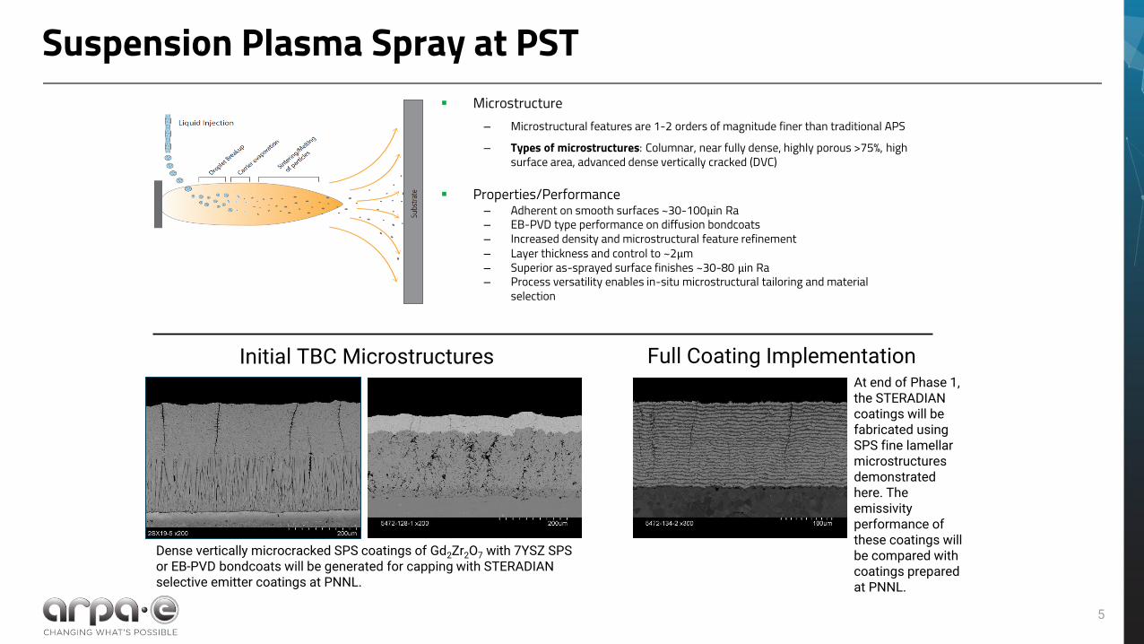
Suspension Plasma Spray at PST
5
▪ Microstructure– Microstructural features are 1-2 orders of magnitude finer than traditional APS– Types of microstructures: Columnar, near fully dense, highly porous >75%, high
surface area, advanced dense vertically cracked (DVC)
▪ Properties/Performance– Adherent on smooth surfaces ~30-100µin Ra– EB-PVD type performance on diffusion bondcoats– Increased density and microstructural feature refinement– Layer thickness and control to ~2µm– Superior as-sprayed surface finishes ~30-80 µin Ra– Process versatility enables in-situ microstructural tailoring and material
selection
Initial TBC Microstructures Full Coating Implementation
Dense vertically microcracked SPS coatings of Gd2Zr2O7 with 7YSZ SPS or EB-PVD bondcoats will be generated for capping with STERADIAN selective emitter coatings at PNNL.
At end of Phase 1, the STERADIAN coatings will be fabricated using SPS fine lamellar microstructures demonstrated here. The emissivity performance of these coatings will be compared with coatings prepared at PNNL.

Team members and roles
6
▸Oggy Ilic (UMN)
– SEC Design
– Photonics theory and modeling
▸Bruce Bernacki (PNNL)
– SEC Design
– Photonics theory and modeling
– Optical component manufacturing
▸Molly O’Connor (PST)
– TBC Design and Fabrication
– Thin film coating characterization
– Thermal cycling
▸Matt Jore (Montana Technologies)
– T2M Analysis
– Market opportunity identification and engagement
▸Charles Bonham (PNNL)
– Thin film coating fabrication

Major milestones, tasks, goals & risks
▸Demonstrate attainment of emissivity FOM target of 35% between 4 and 4.5 µm
▸Demonstrate pathway for commercial-scale implementation on complex turbine blade surfaces
▸Increased risk for coating delamination
– Minimize thermal expansion differences
– Utilize high-temperature annealing to form metal-oxygen-metal bonds at the interfaces
– Avoiding materials that form alloys or solid solutions with lower melting point than the base materials
7
▸Downselect STERADIAN candidates and begin fabrication (Q2)
▸Validate attainment of emissivity target (Q4)
▸Complete FCT and JETS thermal cycling tests (Q5)
▸Complete preliminary TEA (Q5)
▸Complete mechanical property testing for Phase 2 Go/no-go (Q6)
Major Milestones Goals & Risks

T2M and aspirational follow-on plans
8
▸Develop estimates for STERADIAN coating manufacturing costs
▸Use updated emissivity data collected on samples to update CFD simulations of impacts on turbine output
▸Assess payback period for deployments in gas and aviation turbine systems
▸TEA will help support discussions for proceeding into a Phase 2 program
▸Results and conclusions from the Phase 1 project will facilitate follow-on discussions with turbine manufacturers