ultra hd forum guidelines v1.3 · pdf file4/24/2017 · ultra hd forum phase a...
TRANSCRIPT

Ultra HD Forum: Phase A Guidelines
April 24 , 2017 Revision: 1.3
Ultra HD Forum 8377 Fremont Blvd., Suite 117,
Fremont, CA 94538 UNITED STATES
Ultra HD Forum Phase A Guidelines, Revision: 1.3 April 24 , 2017
page: 2/84
Notice The Ultra HD Forum Guidelines are intended to serve the public interest by providing recommendations and procedures that promote uniformity of product, interchangeability and ultimately the long-term reliability of audio/video service transmission. This document shall not in any way preclude any member or nonmember of the Ultra HD Forum from manufacturing or selling products not conforming to such documents, nor shall the existence of such guidelines preclude their voluntary use by those other than Ultra HD Forum members, whether used domestically or internationally. The Ultra HD Forum assumes no obligations or liability whatsoever to any party who may adopt the guidelines. Such adopting party assumes all risks associated with adoption of these guidelines, and accepts full responsibility for any damage and/or claims arising from the adoption of such guidelines. Attention is called to the possibility that implementation of the recommendations and procedures described in these guidelines may require the use of subject matter covered by patent rights. By publication of these guidelines, no position is taken with respect to the existence or validity of any patent rights in connection therewith. Ultra HD Forum shall not be responsible for identifying patents for which a license may be required or for conducting inquiries into the legal validity or scope of those patents that are brought to its attention. Patent holders who believe that they hold patents which are essential to the implementation of the recommendations and procedures described in these guidelines have been requested to provide information about those patents and any related licensing terms and conditions. All Rights Reserved © Ultra HD Forum. 2016 Revision History Version Date Revision 1 released for select external review April 18, 2016 Revision 1.1 released to the public July 15, 2016 Revision 1.2 released to the public December 16, 2016 Revision 1.3 released to the public April 24, 2017

Ultra HD Forum Phase A Guidelines, Revision: 1.3 April 24 , 2017
page: 3/84
Table of Contents 1. PURPOSE AND SCOPE .......................................................................................................................... 62. REFERENCES .......................................................................................................................................... 9
2.1 Reference List 92.2 Brief Summary of ITU-R BT.709, BT.2020, and BT.2100 11
3. TERMS AND ACRONYMS ..................................................................................................................... 123.1 Terms 123.2 Acronyms and Abbreviations 14
4. PHASES AND TIMEFRAMES ................................................................................................................ 164.1 Phase A 164.2 Future Phases 18
5. USE CASES............................................................................................................................................ 205.1 MVPD Platform Delivery 205.2 IP Network Delivery 20
6. PRODUCTION AND POST PRODUCTION ........................................................................................... 226.1 HDR/WCG Technologies 23
6.1.1 Perceptual Quantization (PQ) 236.1.2 Hybrid Log-Gamma (HLG) 246.1.3 Recommendation ITU-R BT.2100 246.1.4 Static Metadata – SMPTE ST 2086, MaxFALL, MaxCLL 246.1.5 HDR10 256.1.6 UHD Phase A HDR Technologies 256.1.7 HDR10 Metadata Generation 266.1.8 HDR10 Metadata Carriage 266.1.9 Signaling Transfer Function, Color Space and Matrix Coefficients 276.1.10 Peak Brightness 29
6.2 Production for Pre-recorded Content 306.2.1 Camera Requirements 316.2.2 Reference Monitor 326.2.3 On-Set / Near-Set Monitoring 336.2.4 Color Grading 336.2.5 Channel-based Immersive Audio Post Production 34
6.3 Production for Live Content 356.3.1 Live Production in Trucks or Studio Galleries 366.3.2 Production with encodings other than PQ and HLG 376.3.3 Channel-based Immersive Audio Production 37
7. SECURITY .............................................................................................................................................. 407.1 Content Encryption 407.2 Forensic Watermarking 41
7.2.1 Introduction 417.2.2 Use Cases 417.2.3 Distribution 427.2.4 One-Step Watermarking 437.2.5 Two-Step Watermarking 43
Ultra HD Forum Phase A Guidelines, Revision: 1.3 April 24 , 2017
page: 4/84
8. REAL-TIME PROGRAM SERVICE ASSEMBLY ................................................................................... 488.1 Maintaining Dynamic Range and Color Space Parameters 488.2 Conversion from SDR/BT.709 to PQ10/HLG10 488.3 Conversion between Transfer Functions 518.4 Conversion from PQ10/HLG10 to SDR/BT.709 51
9. DISTRIBUTION ....................................................................................................................................... 539.1 Production Processing and Contribution 54
9.1.1 Video 559.1.2 Audio 579.1.3 Closed Captions and Subtitles 57
9.2 Broadcast Center Processing and Primary Distribution 579.3 Final Distribution from MVPD/OTT Provider Processing 60
9.3.1 Bit Depths 609.3.2 Video 609.3.3 Adaptive Bitrate (ABR) Streaming 619.3.4 Audio 629.3.5 Closed Captions and Subtitles 63
9.4 Transport 6310. DECODING AND RENDERING .............................................................................................................. 64
10.1 Decoding 6410.2 Rendering 6510.3 Overlays Inserted at the Consumer Device 65
11. FORMAT INTEROPERABILITY ............................................................................................................. 6711.1 Legacy Display Devices 6811.2 Down-conversion at the Service Provider 6811.3 Down-conversion at the STB 6911.4 Spatial Resolution Up-conversion of Legacy Services 7111.5 Interoperability of Atmos Channel-based Immersive Audio 73
12. INTRODUCTION TO ANNEXES ............................................................................................................ 7413. ANNEX A: OVER-THE-AIR BROADCAST USE CASE ......................................................................... 7514. ANNEX B: NEXT GENERATION AUDIO ............................................................................................... 76
14.1 Why Next Generation Audio? 7614.2 What is Next Generation Audio? 7614.3 Next Generation Audio Example Use Cases 77
15. ANNEX C: ICTCP COLOR SPACE ......................................................................................................... 7816. ANNEX D: ACES WORKFLOW FOR COLOR AND DYNAMIC RANGE .............................................. 7917. ANNEX E: SL-HDR1 ............................................................................................................................... 8118. ANNEX F: ISO 23001-12, SAMPLE VARIANTS ................................................................................... 83
Ultra HD Forum Phase A Guidelines, Revision: 1.3 April 24 , 2017
page: 5/84
Index of Tables and Figures Table 1 Summary Comparison of ITU-R BT.709, BT.2020, and BT.2100 ................................. 11Table 2 UHD Phase A Workflow Parameters .............................................................................. 17Table 3 UHD Phase A Content Parameters .................................................................................. 18Table 4 Signaling Transfer Function, Color Space and Matrix Coefficients ............................... 28Table 5 SMPTE Registry UL’s for Transfer Function, Color Primaries and Coding Equations . 29Table 6 Pre-recorded Content Interface Descriptions ................................................................... 31Table 7 Compression and Distribution Nodes and Interfaces ...................................................... 53Table 8 SDI Input Standards for 2160p Content .......................................................................... 54Table 9 Contribution Bitrates and Key Parameters ...................................................................... 56Table 10 Primary Distribution Bitrates and Key Parameters ........................................................ 59Table 11 Existing Practices for Real-Time Program Service Distribution Formats ..................... 60Table 12 Final Distribution Bitrates and Key Parameters ............................................................ 61Table 13 Example Bitrates for Video Streams ............................................................................. 62Table 14 ACES Workflow Model ................................................................................................ 79 Figure 1 Content Production and Distribution Workflow ............................................................ 23Figure 2 Pre-recorded Content Production Workflow and Interfaces .......................................... 30Figure 3 Channel-based Immersive Audio Post-Production ........................................................ 34Figure 4 Channel-based Immersive Audio Live Production ........................................................ 38Figure 5 One-Step watermark performed on the client side ......................................................... 43Figure 6 Two-step watermarking .................................................................................................. 44Figure 7 Watermark preprocessing in the baseband domain for two-step watermarking ............ 44Figure 8 Watermark preprocessing in the encoded domain for two-step watermarking .............. 45Figure 9 Watermark embedding, second step of two-step watermarking .................................... 45Figure 10 ABR playlist embedding .............................................................................................. 46Figure 11 Transport at the media layer using MPEG SEI NALUs ............................................... 47Figure 12 Sample Live Workflow with Mixed Format Source Content ...................................... 50Figure 13 Distribution Nodes and Interfaces ................................................................................ 53Figure 14 Contribution Workflow ................................................................................................ 55Figure 15 Primary Distribution to an MVPD or Station ............................................................... 58Figure 16 Primary Distribution to an OTT Provider .................................................................... 59Figure 17 Down-conversion at the Headend ................................................................................ 69Figure 18 Down-conversion at the STB ....................................................................................... 70Figure 19 Spatial Resolution Up-conversion of Legacy Services ................................................ 71Figure 20 NGA Distribution Overview ........................................................................................ 76Figure 21 NGA Consumer Domain .............................................................................................. 77Figure 22 ACES Workflow Model ............................................................................................... 79Figure 23 Phase B SL-HDR1 Processing, Distribution, Reconstruction, and Presentation ......... 82Figure 24 Transport at the container layer using a track in an ISOBMFF file ............................. 83

Ultra HD Forum Phase A Guidelines, Revision: 1.3 April 24 , 2017
page: 6/84
1. Purpose and scope
The purpose of this document is to describe consistent methods for the creation and delivery of Ultra HD content for consumer distribution along with a uniform set of characteristics that may be combined to produce content that can be considered “Ultra HD,” referred to as “UHD Phase A” in this document. (See Table 3 for characteristics of UHD Phase A services.) The scope includes delivery via the Internet, satellite, terrestrial broadcast and cable as transmission methods. It does not include encode and delivery of content via storage media, such as Blu-ray® disc, HDD, SCSA devices, or similar, nor does it include encode and delivery of Digital Cinema content.
The goal is to create consistency across the industry for ensuring interoperability and a high quality experience for consumers. While this document provides context with respect to content creation, the primary purpose of this document is to define guidelines for proper delivery of UHD Phase A content from the studio producer or the live event to the consumer via a linear (real-time) service.
This document recommends profiles and practices to be used across each of the elements in a distribution chain to maximize end-to-end interoperability. References supporting the recommendations are provided to the extent possible. However, in many cases, industry practices are advancing more quickly than existing documentation. In the cases where technologies are in the process of being developed and/or standardized, these guidelines also provide associated time line expectations where possible. All the recommendations represent the consensus view of the Ultra HD Forum based on these references, its members’ expertise and experience, and/or results from Ultra HD Forum Interop events.
The Ultra HD Forum intends the Phase A Guidelines to be a "living document" and plans to release new revisions as more data becomes available, more learning is accumulated across deployments, and more interops and trials are conducted, while keeping the same scope for the document.
For the purpose of this document, the Ultra HD Forum is considering the following UHD Phase A content and service types, which have different workflow characteristics:
• Content Types: o Live content – content that is distributed to consumers in real-time as it is
produced, such as sports, news, awards shows, reality programs, talent shows, debates, etc. Live production workflows do not include a post-production step and creative intent is set in the control room or truck. Note that content produced in this manner may also be captured for subsequent re-broadcast.
o Pre-recorded content – content that is fully produced prior to distribution to consumers, such as sitcoms, dramas, advertisements, documentaries, etc. Pre-recorded production workflows include post-production steps, and creative intent is set during post-production.
• Service Types: o Real-time Program Services – services consisting of a linear, pre-scheduled
stream of content that is assembled in real-time for distribution to consumers such as a broadcast television channel, cable network, etc. Real-time Program

Ultra HD Forum Phase A Guidelines, Revision: 1.3 April 24 , 2017
page: 7/84
Services are comprised of Live and/or Pre-recorded content and may also include graphic overlays, such as station logos, emergency text crawls, etc.
o On-Demand Services – (largely out of scope, see below) services consisting of content that is distributed upon request by a consumer rather than according to a linear, pre-scheduled timetable, such as Hulu, Netflix, MVPD on-demand catalogs, etc. On-Demand Services consist of Pre-recorded content and content that was originally Live and was recorded for later distribution.
The initial and primary focus of the Ultra HD Forum is on Real-time Program Services because they may be the most challenging for an Ultra HD end-to-end workflow. On-Demand Services are largely out of scope. However, guidelines contained herein related to producing Live content may be valuable to On-Demand Service providers who are offering content that was originally produced for Live distribution using a linear workflow, and has been repurposed as a VOD asset, e.g., via caching at the point of final distribution, for start-over, catch-up, or trick play. With this in mind, the scope of this document is defined as follows:
In scope:
• Pre-recorded and Live content production o Cameras o Monitoring o Color grading for Pre-recorded content o HDR/WCG technologies
• Metadata • Security • Distribution and Compression
o Content master format o Content mezzanine format o Encoding codecs, methods and recommendations o Transcode codecs, methods and recommendations o Approximate ranges of bitrates through the entire processing chain o Distribution and transport methods
• Real-time Program Stream assembly • Conversion between SDR and HDR formats and between different HDR formats • Interface guidelines for connecting systems and functions throughout the production
and delivery of the content • Backward compatibility for legacy systems
Out of scope:
• Filming techniques (e.g., lighting, camera settings, etc.) • TV settings • Encoder settings • Subjective analysis of overall content quality • TV technology guidelines (e.g., OLED vs. Quantum Dots)
Ultra HD Forum Phase A Guidelines, Revision: 1.3 April 24 , 2017
page: 8/84
• Color grading guidelines (e.g., luma, saturation and contrast preferences)

Ultra HD Forum Phase A Guidelines, Revision: 1.3 April 24 , 2017
page: 9/84
2. References
This section contains references used in this text, which are an essential component of these guidelines. At the time of publication, the editions indicated were valid. All standards are subject to revision, and parties are encouraged to investigate the applicability of the most recent editions of the materials listed in this section.
2.1 Reference List [1] Recommendation ITU-T H.222.0 | ISO/IEC 13818-1:2000, “Information Technology—
Generic coding of moving pictures and associated audio information - Part 1: Systems” [2] Recommendation ITU-R BT.709, “Parameter values for the HDTV standards for production
and international programme exchange” [3] Recommendation ITU-R BT.2020, “Parameter values for ultra-high definition television
systems for production and international programme exchange” [4] Recommendation ITU-R BT.1886, “Reference electro-optical transfer function for flat panel
displays used in HDTV studio production” [5] Recommendation ITU-R BT.2100, “Image parameter values for high dynamic range
television for use in production and international programme exchange”, http://www.itu.int/rec/R-REC-BT.2100
[6] Report ITU-R BT.2390, “High dynamic range television for production and international programme exchange” , https://www.itu.int/pub/R-REP-BT.2390-2016 (companion report to ITU-R Recommendation BT.2100)
[7] Recommendation ITU-R BT.2087-0, “Colour conversion from ITU-R BT.709 [2] to ITU-RBT.2020 [3]”
[8] SMPTE ST 2084, “High Dynamic Range Electro-Optical Transfer Function of Mastering Reference Displays”
[9] SMPTE ST 2086, “Mastering Display Color Volume Metadata Supporting High Luminance and Wide Color Gamut Images”
[10] SMPTE HDR Study Group report, https://www.smpte.org/sites/default/files/Study%20Group%20On%20High-Dynamic-Range-HDR-Ecosystem.pdf
[11] DVB UHD-1 Phase 1 specification, http://www.etsi.org/deliver/etsi_ts/101100_101199/101154/02.01.01_60/ts_101154v020101p.pdf
[12] DVB DASH specification, https://www.dvb.org/resources/public/standards/a168_dvb-dash.pdf
[13] CTA, “4K Ultra High-Definition TV”, http://www.cta.tech/CorporateSite/media/Membership-Media/Video-Technology-Consumer-Definitions.pdf
[14] Recommendation ITU-R BT.814, “Specifications and alignment procedures for setting of brightness and contrast on displays”
Ultra HD Forum Phase A Guidelines, Revision: 1.3 April 24 , 2017
page: 10/84
[15] HDMI 2.0a specification, http://www.hdmi.org/manufacturer/hdmi_2_0/hdmi_2_0a_faq.aspx
[16] Dynamic Adaptive Streaming over Hyper Text Transfer Protocol (HTTP) - Industry Forum (DASH-IF)
[17] DCI Specification, Version 1.2 with Errata as of 30 August 2012 Incorporated [18] CTA-608-E R-2014, “Line 21 Data Services”, http://www.cta.tech/Standards/Standard-
Listings/R4-3-Television-Data-Systems-Subcommittee.aspx [19] CTA-708-E (ANSI), “Digital Television (DTV) Closed Captioning” ,
http://www.cta.tech/Standards/Standard-Listings/R4-3-Television-Data-Systems-Subcommittee.aspx
[20] ETSI 300 743, “Digital Video Broadcasting (DVB); Subtitling systems”, http://www.etsi.org/deliver/etsi_en/300700_300799/300743/01.03.01_60/en_300743v010301p.pdf
[21] ETSI 300 472, ”Digital Video Broadcasting (DVB); Specification for conveying ITU-R System B Teletext in DVB bitstreams”, http://www.etsi.org/deliver/etsi_en/300400_300499/300472/01.03.01_60/en_300472v010301p.pdf
[22] SCTE-27, “Subtitling Methods for Broadcast Cable” http://www.scte.org/documents/pdf/standards/SCTE_27_2011.pdf
[23] W3C: “TTML Text and Image Profiles for Internet Media Subtitles and Captions (IMSC1)”, [Candidate] Recommendation, W3C, www.w3.org.
[24] ATSC: “Techniques for Establishing and Maintaining Audio Loudness for Digital Television,” Doc. A/85, Advanced Television Systems Committee, Washington, D.C., 12 March 2013, http://atsc.org/recommended-practice/a85-techniques-for-establishing-and-maintaining-audio-loudness-for-digital-television/
[25] ISO/IEC: “MPEG-4 -- Part 10: Advanced Video Coding,” Doc. ISO/IEC 14496-101 [26] ISO/IEC: “Information technology -- High efficiency coding and media delivery in
heterogeneous environments -- Part 2: High efficiency video coding, ” Doc. ISO/IEC 23008-2:20152
[27] ISO/IEC 14496-3:2009, “Informational Technology, Coding of Audio-Visual objects, Part 3: Audio”
[28] ETSI 102 366 v1.3.1 (2014-08), “Digital Audio Compression (AC-3, Enhanced AC-3) Standard”
[29] SMPTE RP 431-2, “D-Cinema Quality — Reference Projector and Environment" [30] CTA 861, “A DTV Profile for Uncompressed High Speed Digital Interfaces”
https://www.cta.tech/Standards/Standard-Listings/R4-8-DTV-Interface-Subcommittee/CEA-861-E.aspx
[31] W3C: “HTML5, A vocabulary and associated APIs for HTML and XHTML” https://www.w3.org/TR/html5/
1 Also published by ITU as ITU-T Recommendation H.264. 2 Also published by ITU as ITU-T Recommendation H.265.

Ultra HD Forum Phase A Guidelines, Revision: 1.3 April 24 , 2017
page: 11/84
[32] ETSI TS 103 433 v1.1.1 (2016-08) "High-Performance Single Layer Directly Standard Dynamic Range (SDR) Compatible High Dynamic Range (HDR) System for use in Consumer Electronics devices (SL-HDR1)"
[33] ETSI TS 103 420, “Object-based audio coding for Enhanced AC-3 (E-AC-3)”. [34] SMPTE ST 337, “Format for Non-PCM Audio and Data in AES 3 Serial Digital Audio
Interface” [35] Recommendation ITU-R BS.1770-4, “Algorithms to measure audio programme loudness
and true-peak audio level” [36] SMPTE ST 2067-21, “Interoperable Master Format — Application #2E,” 2016 [37] “Guidelines for Implementation: DASH-IF Interoperability Points v3.1,”
http://dashif.org/wp-content/uploads/2015/10/DASH-IF-IOP-v3.1.pdf [38] MovieLabs, “MovieLabs Specification for Enhanced Content Protection, v1.1” [39] ISO/IEC 23001-12:2015, “Information technology -- MPEG systems technologies - Part
12: Sample Variants in the ISO base media file format”
2.2 Brief Summary of ITU-R BT.709, BT.2020, and BT.2100
The Ultra HD Forum Guidelines document refers to ITU-R BT.709 [2], BT.2020 [3], and BT.2100 [5] that address transfer function, color space, matrix coefficients, and more. The following table is a summary comparison of those three documents. Please note that this is merely a summary, and the documents contain considerably more information.
Table 1 Summary Comparison of ITU-R BT.709, BT.2020, and BT.2100
ITU-R BT.709 ITU-R BT.2020 ITU-R BT.2100 Spatial Resolution HD UHD, 8K HD, UHD, 8K Framerates* 24, 25, 30, 50, 60 24, 25, 30, 50, 60,
100, 120 24, 25, 30, 50, 60, 100, 120
Interlace/Progressive Interlace, Progressive Progressive Progressive Color Space** BT.709 BT.2020 BT.2020 Dynamic Range SDR (BT.1886 [4]) SDR (BT.1886 [4]) HDR (PQ and HLG) Bit Depth 8, 10 10, 12 10, 12 Color Representation RGB, YCBCR RGB, YCBCR RGB, YCBCR, ICTCP
*Framerates include both integer and fractional values (including 120/1.001 for BT.2020 and BT.2100).
**Refer to the ITU-R documents for actual color primary values.

Ultra HD Forum Phase A Guidelines, Revision: 1.3 April 24 , 2017
page: 12/84
3. Terms and Acronyms
3.1 Terms This guideline contains the following terms and definitions:
Adaptive Bit Rate A technique used in streaming multimedia over computer networks, in which multiple versions of a single content source are provided, each encoded at different bitrates; the client device monitors the available bandwidth and CPU capacity in real time, and switches between streaming the different encodings, choosing the highest bitrate (i.e., highest quality) according to available resources.
Bit Depth The number of bits used per component. It describes the number of increments for both brightness and color.
Color Gamut The subset of colors that can be accurately represented within a given color space, or by a certain output device.
Color Space A specific organization of colors, allowing for their reproducible representation. BT.2020 [3] and BT.709 [2] are examples of color spaces.
Color Volume Combined color gamut and luminance characteristics.
DCI-P3 Color gamut defined in SMPTE RP 431-2 [29].
Electro-Optical Transfer Function
The transfer function that maps digital pixel values to values of display light.
Forensic Watermarking
Forensic Watermarking is a process that consists of modifying multimedia content (e.g., a video, a song, a piece of text) to encode a Watermark Identifier in an imperceptible manner while still allowing recovery of the Watermark Identifier even if the content is further modified.
HLG10 The Hybrid Log-Gamma OETF described in BT.2100 [5] together with BT.2020 [3] color space and 10-bit depth.
HDR10 A specific profile of video characteristics defined by CTA as: ST 2084 [8] (PQ), BT.2020 [3] color space, 10-bit component depth, inclusion of ST 2086 [9] metadata, inclusion of MaxFALL and MaxCLL metadata.
High Dynamic Range Greater than or equal to the contrast ratio that could be derived from 13 f-stops.
High Frame Rate Content with a relative rate greater than 24 frames per second for motion pictures and greater than 60 fps for television content.
Hybrid Log-Gamma Hybrid Log-Gamma OETF, EOTF, and OOTF as defined in BT.2100 [5].
Immersive Audio An audio system that enables high spatial resolution in sound source localization in azimuth, elevation and distance, and provides an increased sense of sound envelopment.

Ultra HD Forum Phase A Guidelines, Revision: 1.3 April 24 , 2017
page: 13/84
MaxCLL Maximum Content Light Level – greatest pixel light value of any video frame in the program.
MaxFALL Maximum Frame-Average Light Level – greatest average pixel light value of any video frame in the program.
Modulation Transfer Function
The contrast performance of an optical system such as a lens as a function of spatial frequency.
Multichannel Video Programming Distributor
A service provider that delivers video programming services, usually for a subscription fee (pay television).
Nit Unit of luminance measurement, weighted by the human visual system, formally specified in “candela per meter squared” (the term “nits” is used informally for convenience).
Opto-Electronic Transfer Function
The transfer function that maps scene light captured by the camera into digital pixel values.
Opto-optical Transfer Function
The overall transfer function that maps scene light captured by the camera to light values produced by the display.
Perceptual Quantization
A high dynamic range EOTF used for HDR. PQ is specified in ST 2084 [8].
PQ10 The Perceptual Quantization EOTF described in ST 2084 [8] together with BT.2020 [3] color space and 10-bit depth (i.e., PQ10 may be used without metadata).
Resolution The number of vertical and horizontal pixels available on a display device.
Set of Variants A Set of Variants contains Variants of a segment of multimedia content that can be used interchangeably at a given moment for the duration of the Variants. Variants in a Set of Variants are of the same duration. Sets of Variants for a given asset are generated during the pre-processing step in a two-step watermarking system.
Standard Dynamic Range
Content graded as per BT.1886 [4] and BT. 709 [2] for HD television.
Variant Generated by a Forensic Watermarking technology, a Variant is an alternative representation of an asset for a given segment of multimedia content. The size of the segment is variable (from a few Bytes up to a group of pictures).
Variant Sequence Generator
Based on a Watermark Identifier, a Variant Sequence Generator (VSG) selects in each Set of Variants a single Variant to produce a Variant Sequence. The Variant Sequence Generator is part of the embedding step in a two-step watermarking system.
Variant Sequence A Variant Sequence is a sequence of Variants generated based on a particular Watermark Identifier.
Color Volume Transform
A technique used to map a coordinate in one color volume to a coordinate in another color volume.
UHD-1 UHD at resolution of 3840 H by 2160 V.

Ultra HD Forum Phase A Guidelines, Revision: 1.3 April 24 , 2017
page: 14/84
UHD-2 UHD at resolution of 7680 H by 4320 V.
UHD Phase A Term used in this document to for content that conforms to the parameters shown in Table 3.
Wide Color Gamut Color gamut wider than the gamut of BT.709 [2].
Watermark Identifier
A serialization number that is embedded in the content by the watermarking system and makes the file unique. Examples of data used as a Watermark Identifier are session IDs, client IDs, device IDs, firmware versions, timestamps, etc. A Watermark Identifier is also routinely referred to as payload or message.
3.2 Acronyms and Abbreviations ABR Adaptive Bit Rate
AVC Advanced Video Coding
CA Conditional Access
CDN Content Delivery Network
CG Character Generator
CGI Computer Generated Imagery
DVE Digital Video Effects
EMB Watermark EMBedder
EOTF Electro-Optical Transfer Function
HD High Definition
HDR High Dynamic Range
HEVC High Efficiency Video Coding
HFR High Frame Rate
HLG Hybrid Log-Gamma
HTTP Hyper Text Transfer Protocol
IP Internet Protocol
IPTV Internet Protocol Television
LUT Look Up Table
MTF Modulation Transfer Function
MVPD Multichannel Video Programming Distributor
NALU Network Abstraction Layer Unit
NGA Next Generation Audio
OETF Opto-Electronic Transfer Function
OOTF Opto-Optical Transfer Function
OTA Over-the-Air (i.e., terrestrial transmission of content)

Ultra HD Forum Phase A Guidelines, Revision: 1.3 April 24 , 2017
page: 15/84
OTT Over-the-Top (i.e., Internet-based transmission of content)
PQ Perceptual Quantization
PVR Personal Video Recorder
RTP Real-Time Transport Protocol
SD Standard Definition
SEI Supplemental Enhancement Information
SDR Standard Dynamic Range
STB Set Top Box
UDP User Datagram Protocol
UHD Ultra High Definition (see “UHD Phase A” in Section 2.2 above for use of this term within the scope of this document)
URI Uniform Resource Identifier
VSG Variant Sequence Generator
VOD Video-on-Demand
WCG Wide Color Gamut
WM WaterMark

Ultra HD Forum Phase A Guidelines, Revision: 1.3 April 24 , 2017
page: 16/84
4. Phases and Timeframes
This document addresses UHD Phase A methods and technologies that are expected to be deployable within the 2016 timeframe which we define as “Phase A.” Future versions of this document may address technologies that are expected to be employable beyond 2016 as future phases (e.g., Phase B, Phase C).
The high-level media attributes for new services expected to launch in the Phase A 2016 timeframe are listed in Section 4.1. Future phases are out of scope of this document; however, some high level guidance is suggested in Section 4.2 below and in the Annexes. Detailed recommendations are grouped into Production / Post-Production, Distribution (includes compression and distribution for contribution, primary and final delivery stages), and Decoding / Rendering.
The Ultra HD Forum applies the following criteria to select recommended technologies for a given Phase:
1. Viability is near term based on sufficiently low technical complexity 2. There is broad interest in the technology within the industry, including from service
providers 3. The technology enables Real-time Program Services consisting of Live and/or Pre-
recorded content elements 4. The technology is expected to be commercially available or described in a reasonably
accessible specification within the given Phase timeframe
4.1 Phase A UHD Phase A content and services are expected to be distributed in 2016 and beyond via OTT or MVPD. OTA broadcast services are not expected to be commercially offered in 2016 and thus will be addressed in future phases rather than in Phase A.
For the purposes of this document, UHD Phase A includes the following characteristics: • Resolution – greater than or equal to 1080p and lower than or equal to 2160p,
(progressive format; BT.2100 [5] does not include interlaced formats) • Wide Color Gamut – color gamut wider than BT.709 [2] • High Dynamic Range – greater than or equal to the contrast ratio that could be
derived from 13 f-stops of dynamic range • Bit depth – 10-bit • Frame rates – up to 60fps (integer frame rates are preferred; note that cinematic
content may opt to use lower frame rates, e.g., see DCI specification)

Ultra HD Forum Phase A Guidelines, Revision: 1.3 April 24 , 2017
page: 17/84
• Audio – 5.1 channel surround sound or channel-based Immersive Audio3 (2.0 stereo is possible; however, 5.1 or channel-based Immersive Audio are preferred for a premium experience; see also Section 14 on future next-generation audio)
• Closed Captions/Subtitles – CTA 708/608, ETSI 300 743, ETSI 300 472, SCTE-27, IMSC1
The following terms are used in this document for HDR and HDR plus WCG:
• HLG: The Hybrid Log-Gamma OETF defined in BT.2100 [5] • HLG10: The Hybrid Log-Gamma OETF described in BT.2100 [5] together with
BT.2020 [3] color space and 10-bit depth. • PQ: The Perceptual Quantization EOTF defined in ST 2084 [8] • PQ10: The Perceptual Quantization EOTF described in ST 2084 [8] together with
BT.2020 [3] color space and 10-bit depth • HDR10: The Perceptual Quantization EOTF with BT.2020 [3] color space, 10-bit
depth, ST 2086 [9] static metadata, and the MaxCLL and MaxFALL static metadata [13]
Table 2 UHD Phase A Workflow Parameters
Content Creation & Mastering
Defined and documented standard workflows for Live and Pre-recorded content
Service Type Real-time Program Services; On-Demand content that was originally offered as Live content
Network Type Unicast (including Adaptive Bit Rate) Broadcast, Multicast
Transport MPEG TS, Multicast IP, DASH ISO BMFF Interface to TVs (source format)
IP connected (for OTT content delivered via managed or unmanaged network) HDMI (for services delivered via a STB, e.g., OTT, MVPD)
Backward Compatibility Native (HLG), simulcast (HDR10/PQ10), decoder based (optional)
3 Note that Immersive Audio can also include object- and scene-based audio as well as channel-
based audio; however, these are not expected in deployments of Real-time Program Services in 2016.

Ultra HD Forum Phase A Guidelines, Revision: 1.3 April 24 , 2017
page: 18/84
Table 3 UHD Phase A Content Parameters
Spatial Resolution 1080p* or 2160p Color Space BT.709 [2], BT.2020 [3] Bit Depth 10-bit Dynamic Range SDR, PQ, HLG Frame Rate** 24, 25, 30, 50, 60 Video Codec HEVC, Main 10 Profile, Level 5.1 (single layer) Audio Channels Stereo or 5.1 or channel-based Immersive Audio Audio Codec AC-3, E-AC-3, HE-ACC, AAC-LC Captions/Subtitles Coding CTA 608/708, ETSI 300 743, ETSI 300 472, SCTE-27,
IMSC1 *1080p together with WCG and HDR fulfills certain use cases for UHD Phase A services
and is therefore considered to be an Ultra HD format for the purpose of this document. 1080p without WCG or HDR is considered to be an HD format. The possibility of 1080i or 720p plus HDR and WCG is not considered here. HDR and WCG for multiscreen resolutions may be considered in the future.
**Fractional frame rates for 24, 30 and 60 fps are included, but not preferred. Lower frame rates may be best applied to cinematic content.
For the purpose of Phase A services described in this document, including the above constraint on 1080p content, various combinations of these parameters can be combined to produce “UHD Phase A” content.
4.2 Future Phases The Ultra HD Forum intends to continue to provide guidance beyond the Phase A timeframe of 2016 either via updates to this document or in the form of future documents. Currently, Phase B is being planned for technologies that are expected to be commercially deployable in 2017 and beyond. Although details of future phases are not in the scope of this text, examples of technologies and methods that may be considered are listed below with additional details offered in the Annexes. These are technologies the Ultra HD Forum found unlikely to be commercially used in Phase A, but are actively being evaluated by service providers and/or being documented by international standards development organizations (SDOs). Phase B technologies are limited to those for which commercial deployments may occur in 2017-2020. Such future technologies may include:
• Next Generation Audio (NGA) codecs such as Dolby AC-4, DTS:X, MPEG-H – immersive and/or personalized audio systems using audio objects, channels or higher-order ambisonics (see Section 14)
• Scalable coding (Spatial, Temporal, Color gamut, Dynamic range) • Greater than 10-bit encoding depths • High Frame Rate – Greater than 50 frames per second (fps) for 50Hz regions and
greater than 60 fps for 60Hz regions • 8k spatial resolution

Ultra HD Forum Phase A Guidelines, Revision: 1.3 April 24 , 2017
page: 19/84
• Dynamic metadata for HDR being standardized in the SMPTE ST 2094 Dynamic Metadata for Color Volume Transform suite of standards
• Advances in captioning and subtitling, e.g., to accommodate HDR/WCG • Single-layer HDR technologies (such as SL-HDR1 [32]; see Annex E) • Dual layer HDR technologies (such as Dolby Vision) • ICTCP color space (see Section 15) • Color Remapping Information (CRI)
Not all the above technologies are at the same level of maturity in terms of
specification/standards development and product availability, or commercial readiness for deployment in an end-to-end ecosystem. Some are quite mature and are likely to see deployment very quickly after Phase A. One such example is NGA (Next Generation Audio), as standardization, product/solution readiness, and commercial interests are expected to be well aligned and mature enough for deployments in the 2017 timeframe. Other technologies are less mature, and the Ultra HD Forum will monitor the progress of these technologies as it works on Phase B guidelines.

Ultra HD Forum Phase A Guidelines, Revision: 1.3 April 24 , 2017
page: 20/84
5. Use Cases
The following use cases are intended to provide context for the guidelines defined within this document. They are not intended to be exhaustive, yet they cover those associated with the content creation and distribution ecosystem in Phase A. Note that OTA delivery of UHD Phase A content is not expected in 2016, and thus is out of scope of Phase A; see Section 11.5 for anticipated OTA use cases.
5.1 MVPD Platform Delivery Programming distributors may wish to provide a consumer with a high quality experience via cable, satellite or IPTV or, as a secondary delivery system, OTT. The programming distributor may deliver content to the following devices:
• Set-Top Box (STB) • Other media device (e.g., TV, tablet, smart phone)
The content will need to be transcoded into multiple formats and bit-rates to provide the best
experience to the consumer. The following things will need to be considered: • 1080p with HDR/WCG for low bit-rate delivery
Consumers may be at home or mobile, and will access content across multiple devices. Some
devices may provide the consumer a superior experience based on decoding and display capability, and content should be created with these variables in mind.
5.2 IP Network Delivery Adaptive Bit Rate (ABR) is an HTTP delivery solution suitable for multiple streaming formats, such as HLS (HTTP Live Streaming, implemented by Apple®) or DASH. ABR can be used over a managed network (e.g., DOCSIS 3.x) or an unmanaged network (i.e., the public Internet).
In a managed network, ABR content can be delivered by an MVPD that is also an Internet service provider (ISP), e.g. a cable operator or telco operator. The content is sent over a managed network in IP Services. This is also referred to as IPTV. There are a number of technologies that can be used, e.g., DOCSIS 3.x. MVPDs who are ISPs may also send their IP Services over networks managed by other ISPs in what is known as “TV Everywhere.”
In an unmanaged network, a type of service provider referred to as an edge provider, e.g., Netflix®, Amazon® and others, sends IP services over multiple ISP networks on the public Internet. This is known as over the top (OTT).
Today Live event content producers such as sports league owners and others may choose to provide consumers with a high-quality Ultra HD audio/video experience of a real-time event over an IP network. When content is captured and mastered using parameters described in this document and delivered to compatible displays, IP networks can deliver a high quality consumer experience.

Ultra HD Forum Phase A Guidelines, Revision: 1.3 April 24 , 2017
page: 21/84
So that a high quality experience can be delivered over varying network conditions, the content is transcoded into multiple versions suitable for various bitrates to form sets of encoded content at different bitrate levels. The sets allow seamless switching between the higher and lower bitrate versions of the real-time content, i.e., “adapting” as network conditions vary. In order to make the most efficient use of available bandwidth to the consumer, a content producer will get the best results using advanced picture encoding technologies (e.g., HEVC), which have been engineered specifically for such applications (see also Section 9.3.2).
The following represents the minimum, under normal network conditions, that should be supported from camera to the consumer’s television:
• 1080p resolution with HDR, WCG, and 10-bit depth Phase A UHD ABR content may be delivered via an IP network to the following devices.
MVPD/ISPs: • STBs managed by MVPDs that connect to a television.
OTT or TV Everywhere: • OTT Streaming Boxes (STB) that connect to a television (e.g., game consoles,
Roku® boxes and similar devices). • OTT-capable media devices (e.g., smart TVs, tablets and smart phones) that include a
display panel.
Content producers will continue to deliver programming to customers that are using ‘legacy’ devices (i.e., devices that only support SDR, BT.709 [2] color space and stereo audio). Content distribution network (CDN) partners may need to host both UHD Phase A and legacy files. It should be noted that if the content is delivered to the consumer device via a home Wi-Fi connection, the quality of service may be impacted by the available bandwidth on the home LAN. A wired connection to the device may be preferred.
MVPD/ISPs: • It is expected that there will be Phase A UHD ABR services from MVPD/IPTV
operators to connected UHD TVs over Wi-Fi (MVPD-provided Wi-Fi equipment at consumer premises).
• Deployments are expected on Phase A UHD ABR to connected UHD TVs over DOCSIS 3.0
OTT or TV Everywhere: • It is expected that service providers will offer Phase A UHD content OTT to Wi-Fi or
Ethernet network-connected UHD TVs.
Ultra HD Forum Phase A Guidelines, Revision: 1.3 April 24 , 2017
page: 22/84
6. Production and Post Production
The UHD Forum is concerned with establishing viable workflows both for Real-time Program Services and On Demand content that was originally offered live. Real-time Program Services (aka Linear TV) make frequent use of Pre-recorded material, such as edited inserts, interstitials, etc., which involve production and post-production.
Live content has specific requirements and operating practices that are unlike Digital Cinema, Blu-ray™ disc mastering, or other Pre-recorded content practices. Ultra HD workflows and technologies that are designed for these other delivery methods may not apply to Live content production.
In Phase A, production practices for audio are not expected to differ from those used in current HD content creation. Audio is expected to follow multi-channel workflows established for multi-channel 5.1 surround, and Dolby Atmos delivery using (as appropriate) AC-3 [28], E- E-AC-3 [28], HE-AAC [27], or AAC-LC emission [27]. Although 2.0 stereo sound is possible, UHD Phase A content is considered premium content, and it is therefore recommended that productions provide at least 5.1 channels.
Similarly, in Phase A, production practices for closed captions and subtitles are not expected to differ from those of HD content creation. Closed captions and subtitles follow workflows established for CTA- 608/CTA-708, ETSI 300 743, ETSI 300 472, SCTE-27, or IMSC1 formats.
The remainder of this section will focus on mechanisms for producing the video components of the content.
As content is produced, it is useful to know in advance for which service mode(s) the content is intended. Equally, service providers planning to deliver UHD Phase A content need to have an understanding of the formats in which the content will be supplied.
The following is a diagram providing an overview of the content production and distribution workflow for Real-time Program Services and potentially capturing Live content for later distribution via an On-Demand Service.

Ultra HD Forum Phase A Guidelines, Revision: 1.3 April 24 , 2017
page: 23/84
Figure 1 Content Production and Distribution Workflow
6.1 HDR/WCG Technologies There are many terms in use in the field of HDR television. This section explains the existing terminology and how terms are used in these Guidelines.
Note that currently some UHD displays are capable of accepting BT.2020 [3] content, but as of 2016, no direct view display is available that is capable of rendering the full gamut of colors in the BT.2020 [3] color space. It is assumed that in these cases, the device employs “best effort” gamut mapping tailored to its particular display characteristics, and thus these devices are considered BT.2020 [3]-compatible.
6.1.1 Perceptual Quantization (PQ)
One HDR transfer function defined for use in television is the “Perceptual Quantization” (PQ) proposed by Dolby. This is defined as a display transfer curve, or EOTF. The curve is designed to minimize visibility of banding on a display over the brightness range of 0 to 10,000 cd/m2. SMPTE standardized the PQ curve in ST 2084. ST 2084 specifies the shape of the curve over a range of 0 to 1, but does not specify SDI code values for the 0 and 1 values. An informative annex in ST 2084 [8] gives examples of mapping the 0 to 1 range into the 10-bit space using the conventional range of 64 (black) to 940 (max white). Mappings are also shown for the ranges of 0-1023, and 4-1019.

Ultra HD Forum Phase A Guidelines, Revision: 1.3 April 24 , 2017
page: 24/84
6.1.2 Hybrid Log-Gamma (HLG)
Another HDR transfer function defined is “Hybrid Log-Gamma” (HLG) proposed by the BBC and NHK. This is defined as a camera capture transfer curve, or OETF. This curve was designed to provide HDR while maintaining a degree of compatibility with legacy SDR displays. The HLG curve has been specified in BT.2100 [5]. For 10-bit representation, BT.2100 [5] specifies Black at code 64, and Peak at code 940.
6.1.3 Recommendation ITU-R BT.2100
In February 2016 ITU-R Study Group 6 produced a draft new Recommendation on HDR for use in production and international program exchange. In July 2016, ITU-R Study Group 6 approved the publication of the recommendation, which is now officially known as ITU-R BT.2100 [5]. This recommendation includes the following specifications:
• Spatial resolutions: 1080p, 2160p, 4320p • Frame rates: 24/1.001, 24, 25, 30/1.001, 30, 50, 60/1.001, 60, 100, 120/1.001, 120 • Color space: Same as BT.2020 [3] • Reference Viewing Environment: 5 cd/m2 background and less than or equal to 5
cd/m2 surround • Reference non-linear transfer functions EOTF, OOTF, OETF: PQ and HLG • Color representation: Y’C’BC’R and ICTCP • Color sub-sampling: same alignment as specified in BT.2020 [3] • Bit depth value range: 10 and 12 bits, Narrow (64-940) and Full (0-1023) ranges • Floating point signal representation: Linear RGB, 16-bit floating point
BT.2100 [5] is the primary reference document on HDR for use in production and international program exchange. Note that a full signal specification will need to include the following attributes: spatial resolution, frame rate, transfer function (PQ or HLG), color difference format, integer (10 or 12 bits, narrow or full range) or floating point.
Not all of the parameters listed above are expected to be deployed in Phase A, but are included as informative details.
6.1.4 Static Metadata – SMPTE ST 2086, MaxFALL, MaxCLL
SMPTE has specified a set of static metadata in the ST 2086 [9] Mastering Display Color Volume Metadata Supporting High Luminance and Wide Color Gamut Images standard. Parameters included indicate the characteristics of the mastering display monitor. The mastering display metadata indicates that the creative intent was established on a monitor having the described characteristics. If provided, the implication is that the artistic intent of the content is within the subset of the overall container per the metadata values. The mastering display characteristics include the display primaries and white point as x,y chromaticity coordinates, and the maximum and minimum display luminance. For example, the metadata may indicate that the color gamut of the mastering display is the DCI-P3 gamut in the BT.2020 [3] color space, and the luminance range is a subset of the 0 to 10,000 cd/m2 range provided by PQ.

Ultra HD Forum Phase A Guidelines, Revision: 1.3 April 24 , 2017
page: 25/84
The Blu-ray Disc Association and DECE groups have defined carriage of two additional metadata items:
• MaxFALL – Maximum Frame Average Light Level; this is the largest average pixel light value of any video frame in the program
• MaxCLL – Maximum Content Light Level: this is the largest individual pixel light value of any video frame in the program
Static metadata may be used by displays to control color volume transform of the received program to better reproduce the creative intent as shown on the mastering display, given the capabilities of the display device. However, the use of MaxFALL and MaxCLL static metadata have limitations for use with Live broadcasts since it is difficult to determine a program’s maximum pixel light values during a Live production.
SMPTE is currently working to produce the SMPTE ST 2094 Dynamic Metadata for Color Volume Transform suite of standards, which specify content-dependent metadata for transforming HDR and WCG content for presentation on a display having a different color volume than the display used for mastering such content. Dynamic, content-dependent metadata has the potential for performing more accurate color volume transforms of content than transforms that only use static metadata described in Section 6.1.4. The SMPTE ST 2094 standards are expected to be finalized and published in the 3rd Quarter of 2016; however dynamic metadata is out of scope of Phase A.
6.1.5 HDR10
The term “HDR10” is in widespread use and has been formally and consistently defined by several groups, including DECE and BDA, as:
• Transfer curve: ST 2084 [8] (PQ) • Color space: BT.2020 [3] • Bit depth: 10 bits • Metadata included: ST 2086, MaxFALL, MaxCLL Several delivery formats (e.g. Ultra HD Blu-ray™) have specified delivery using the above
parameters, and are thus considered to be using HDR10.
6.1.6 UHD Phase A HDR Technologies
Two HDR/WCG “packages” are recommended for Phase A due to their conformance with the criteria listed in Section 4 above. The two technologies are:
• HLG10 – inclusive of HLG OETF per BT.2100 [5], BT.2020 [3] color space, and 10-bit sample depth. (See also Section 10.1 for information about carriage of HLG transfer function signaling over HDMI interfaces.)
• PQ10 – inclusive of PQ EOTF per SMPTE ST 2084 [8], Rec. ITU-R BT. 2020 [3] color space, and 10-bit sample depth
HLG10 and PQ10 as defined herein may be used without metadata. This may be
advantageous due to the lack of support in Phase A of certain infrastructures for carrying metadata. For example, although metadata can be carried in SEI messages within an HEVC

Ultra HD Forum Phase A Guidelines, Revision: 1.3 April 24 , 2017
page: 26/84
stream, it is not supported over an SDI interface, and it may not survive multiple decode/encode operations that exist in many broadcast workflows. This is particularly important in Live content production, given its complex, “on-the-fly” workflow. Provided that the reference display peak luminance specifications do not exceed the consumer display, PQ10 can deliver a greater level of certainty in what the viewer will see based on the display-referred nature of its design, particularly when highlights or average picture level are very bright. This is a result of pixel-encoded values, which are prescribed to represent specific picture luminance level. Another distinction drawn between the two schemes is backward compatibility. Content produced using HLG can be displayed on SDR/WCG devices with a degree of compatibility that may be judged acceptable for programs and services according to Report ITU-R BT.2390 [6]. PQ10 content requires a down-conversion step in order to provide acceptable SDR quality. See Section 11 below for a deeper discussion of backward compatibility, including the pros, cons and open questions that apply to various possible methods.
It should be noted that Real-time Program Services are typically comprised of both Live and Pre-recorded content, and it is not recommended that service providers alternate between SDR and HDR signal formats or mix different HDR formats (see Section8.1). In the sections below, both HDR technologies (PQ10, HLG10) will be discussed.
6.1.7 HDR10 Metadata Generation
HDR10 includes the static metadata described in Section 6.1.5. MaxFALL and MaxCLL metadata could be generated by the color grading software or other video analysis software. In Live content production, MaxFALL or MaxCLL metadata is not generated during the production process. By definition, it is not possible to generate MaxFALL or MaxCLL for a Live program because these cannot be known until the entire program is produced, i.e., after the program is over. The special values of ‘0’ (meaning, “unknown”) are allowed for MaxFALL and MaxCLL. It may be possible to set limits on the output and thus pre-determine MaxFALL and MaxCLL even for Live content production. For example, if MaxFALL and MaxCLL metadata values are provided, a video processor could be inserted in order to reduce brightness of any video frames that would exceed the indicated values (similar to the way audio processors are often inserted to enforce audio loudness and peak levels). Carriage of the metadata through the Live production systems is currently only standardized for HEVC-encoded material. If it is desired to use HDR10 in Live content production, default values for ST 2086 [9], MaxFALL and MaxCLL should be determined and entered directly into the encoder via a UI or a file. SMPTE 2086 metadata could be set to values that represent the monitors used for grading during production of the content.
6.1.8 HDR10 Metadata Carriage
As of publication of this document, standards do not exist to carry HDR10 static metadata over an SDI interface. The metadata must be either embedded within the content intended for encoding (for Pre-recorded content) or extracted as an external file for inclusion with the encoded file. If HDR10 is used, metadata must be entered into the encoder via a file or UI. In HEVC [26] and AVC [25] bitstreams, MaxFALL and MaxCLL may be carried in the Content Light Level (CLL) static SEI message (sections D.2.35 (Syntax) and D.3.35 (Semantics), [26]).

Ultra HD Forum Phase A Guidelines, Revision: 1.3 April 24 , 2017
page: 27/84
SMPTE 2086 metadata is carried in the Mastering Display Color Volume SEI, (section D.2.28 (Syntax) and D.3.28 (semantics), [26]).
Note that there may be multiple encoders in the end-to-end broadcast chain. In the event that HDR10 is used and the metadata does not reach the decoder/display, it is expected that the decoder/display will employ “best effort” to render the content accurately.
Given that the insertion, carriage and preservation of static metadata presents new challenges in the broadcast environment, the use of PQ10 or HLG10 may be a practical alternative to the use of HDR10 in some Live workflows. See also Section 6.2.5 on Live content production and Section 9 on content distribution for additional details.
6.1.9 Signaling Transfer Function, Color Space and Matrix Coefficients
The color space, transfer function (SDR or HDR), and matrix coefficients must be known to downstream equipment ingesting or rendering content in order to preserve display intent. This is true for file transfers in file-based workflows and in linear content streams in linear workflows.
In file-based workflows, mezzanine file formats such as IMF/MXF and QuickTime are often used.
In linear workflows, these values are typically signaled in the VUI of an H.265/HEVC or H.264/MPEG-4 AVC bitstream. As shown in the table below, there are two methods of signaling the HLG transfer function.
In one method, the SDR transfer function indicator is signaled in the VUI and the HLG transfer function indicator is transmitted using an alternative transfer characteristics SEI message embedded in the bitstream. In this way, an "HLG aware” STB or decoder/display would recognize that the bitstream refers to content coded with HLG (since it is indicated by the preferred_transfer_characteristics syntax element of the SEI). If an “HLG aware” STB is connected to a TV that does not support HLG, the STB would transmit the SDR indicator over HDMI to the TV. If it is connected to a TV that supports HLG, the STB would copy over the transfer function value in the SEI (to indicate HLG) and transmit this over HDMI to the TV.
In the other method, the HLG transfer function indicator is directly signaled in the VUI in the same way PQ or SDR would be signaled.
In theory it is possible to losslessly convert between the two methods of signaling HLG by flipping the VUI transfer function characteristics indicator value and inserting or removing the alternative transfer characteristic SEI.
Using the first method (i.e., including the SDR transfer function indicator in the VUI and the HLG transfer function indicator in the SEI) enables backward compatibility with SDR/WCG displays. Using the second method (i.e., including the HLG transfer function indicator in the VUI) may also produce acceptable results on SDR displays. Service providers may wish to test both methods.
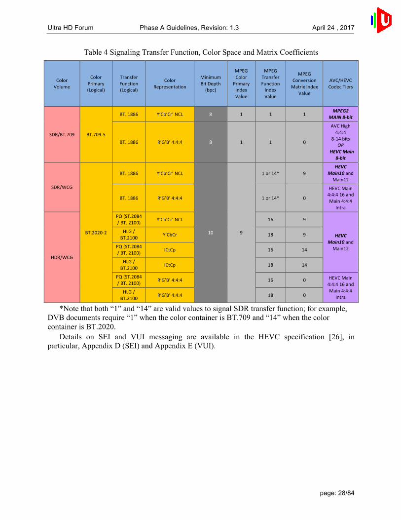
The table below summarizes HEVC Main10 Profile bitstream PQ and HLG indicators. (In HEVC and AVC specifications, the bitstream elements are bolded and italicized to distinguish them from temporary variables and labels.)
Ultra HD Forum Phase A Guidelines, Revision: 1.3 April 24 , 2017
page: 28/84
Table 4 Signaling Transfer Function, Color Space and Matrix Coefficients
ColorVolume
ColorPrimary(Logical)
TransferFunction(Logical)
ColorRepresentation
MinimumBitDepth(bpc)
MPEGColor
PrimaryIndexValue
MPEGTransferFunctionIndexValue
MPEGConversionMatrixIndex
Value
AVC/HEVCCodecTiers
SDR/BT.709 BT.709-5
BT.1886 Y’Cb’Cr’NCL 8 1 1 1MPEG2
MAIN8-bit
BT.1886 R’G’B’4:4:4 8 1 1 0
AVCHigh4:4:4
8-14bitsOR
HEVCMain8-bit
SDR/WCG
BT.2020-2
BT.1886 Y’Cb’Cr’NCL
10 9
1or14* 9HEVC
Main10andMain12
BT.1886 R’G’B’4:4:4 1or14* 0
HEVCMain4:4:416andMain4:4:4
Intra
HDR/WCG
PQ(ST.2084/BT.2100) Y’Cb’Cr’NCL 16 9
HEVCMain10andMain12
HLG/BT.2100 Y’CbCr 18 9
PQ(ST.2084/BT.2100) ICtCp 16 14
HLG/BT.2100 ICtCp 18 14
PQ(ST.2084/BT.2100) R’G’B’4:4:4 16 0 HEVCMain
4:4:416andMain4:4:4
IntraHLG/
BT.2100 R’G’B’4:4:4 18 0
*Note that both “1” and “14” are valid values to signal SDR transfer function; for example, DVB documents require “1” when the color container is BT.709 and “14” when the color container is BT.2020.
Details on SEI and VUI messaging are available in the HEVC specification [26], in particular, Appendix D (SEI) and Appendix E (VUI).

Ultra HD Forum Phase A Guidelines, Revision: 1.3 April 24 , 2017
page: 29/84
Table 5 SMPTE Registry UL’s for Transfer Function, Color Primaries and Coding Equations
ColorVolume
ColorPrimary(Logical)
TransferFunction(Logical)
ColorRepresent
ation
Min.Bit
Depth(bpc)
ColorPrimaries TransferFunctions CodingEquations(MatrixConversions)
SDR/BT.709[Color3]
BT.709-5
BT.1886 Y’Cb’Cr’NCL 8
06.0E.2B.34.04.01.01.06.04.01.01.01.03.03.00.00
06.0E.2B.34.04.01.01.01.04.01.01.01.01.02.00.00
06.0E.2B.34.04.01.01.01.04.01.01.01.02.02.00.00HLG
HDR-SDR[Color3]
HLG/BT.2100
Y’Cb’Cr’NCL 10 06.0E.2B.34.04.01.01.0D.
04.01.01.01.01.0B.00.00
SDR/WCG
[Color5]
BT.2020-2
BT.1886 Y’Cb’Cr’NCL
10 06.0E.2B.34.04.01.01.0D.04.01.01.01.03.04.00.00
06.0E.2B.34.04.01.01.0E.04.01.01.01.01.09.00.00
06.0e.2b.34.04.01.01.0d.04.01.01.01.02.06.00.00HDR/W
CG[Color7]
PQ(ST.2084/BT.2100)
Y’Cb’Cr’NCL
06.0E.2B.34.04.01.01.0D.04.01.01.01.01.0A.00.00
HLG/BT.2100
Y’Cb’Cr’NCL
06.0E.2B.34.04.01.01.0D.04.01.01.01.01.0B.00.00
Additional use cases for production-level signaling wrappers include Apple QuickTime™
Wrapper NCLC Color Tags using MPEG Color Tags and MXF Image Descriptors from ST.2067:21:2016 [36].
As described in Section 8.1, service providers should convert or remap all content into a single, consistent color space and transfer function. Setting the initial values in the encoder should be adequate assuming the encoder is dedicated to a single format.
There is currently no defined means of carrying signaling for transfer function, color space, and HDR-related metadata through the end-to-end supply chain. Gaps exist in the SDI interface, the HDMI interface, mezzanine file wrappers, and other areas. The Ultra HD Forum understands that standards bodies are addressing these issues, and looks forward to new documentation in the near future.
6.1.10 Peak Brightness
Consumer HDR displays will have varying peak brightness, black levels and color gamut, so it will be up to the display or source device to map the color volume of the transmitted content to best match the capabilities of the particular display.
As a PQ signal may carry pixel values as high as 10,000 nits, it is helpful to the display to indicate the actual maximum pixel value to be expected that are creatively pertinent as a basis for color volume transform. HDR10 provides static metadata to assist mapping the transmitted content to the consumer display, enabling a given display to optimize the color volume mapping based on its capability. The use of HDR10 metadata may help to optimize display mapping, but

Ultra HD Forum Phase A Guidelines, Revision: 1.3 April 24 , 2017
page: 30/84
as the metadata may not be practical in Live content, the use of PQ10 may be preferred for Live content. While a system objective is to preserve creative intent with limited perceptual alteration all the way to the consumer display, some perceptual alteration will occur because of different display capabilities both in peak brightness and black levels.
HLG is not specified for use with metadata, and instead has a specified relationship between overall system gamma (implemented as part of the display EOTF) and peak display brightness. An overall system gamma of 1.2 is specified for HLG when displayed on a 1,000 nit monitor. BT.2390 [6] claims the artistic intent of HLG content can be preserved when displaying that content on screens of different brightness (even when that display is brighter than the mastering display), through changing the system gamma. BT.2100 [5] provides a formula to determine overall system gamma based on the desired display peak brightness (overall system gamma at 1.2 is specified for a peak brightness of 1,000 nits). To preserve creative intent, this formula is recommended. Note that that future displays may become available with higher peak brightness capability compared with those available today. In addition, as productions are made with different assumptions of peak brightness, the highlights of the content may be compressed by the knee of a low-peak-brightness HLG curve. It is also possible that archived content made with lower assumed peak brightness will not preserve creative intent when played back on a brighter display.
6.2 Production for Pre-recorded Content This section focuses on the creation and distribution of pre-recorded content intended for inclusion in a Real-time Program Service. This includes all content filmed, captured digitally, or rendered in CGI and delivered via a file format to a service provider. Real-time Program Services may be delivered via MVPD (satellite, Cable, or IPTV) and OTT (and OTA in Phase B). See Section 6.2.5 for production of Live content that is recorded for subsequent re-showing.
The following diagram depicts the interfaces and primary functions within the pre-recorded content creation process.
Figure 2 Pre-recorded Content Production Workflow and Interfaces
The initial scope of this guideline includes definition of six functions and five interfaces. The functional descriptions are described within sub-sections below, and the interface descriptions are described at a high level in the following table.

Ultra HD Forum Phase A Guidelines, Revision: 1.3 April 24 , 2017
page: 31/84
Table 6 Pre-recorded Content Interface Descriptions
Reference Point
Content Creation Functions
Reference Point Description
EC-1 Camera – Content Editor
Raw or log camera footage is ingested into the editing program. This interface may optionally contain metadata from the camera used by the editing program to provide guidance to timeline creation parameters.
EC-2 Camera – Color Grading
Raw or log camera footage is ingested into the color grading solution. This interface may optionally provide camera metadata describing the dynamic range resolution or other camera specific information from the captured footage.
EC-3 Content Editor – Encoding
Edited and color graded content is exported to an encoder for master and/or mezzanine level creation. This includes audio, video, essence, timing and CG content. Often the encoding function is included as part of the Content Editor.
EC-4 Color Grading – Professional Reference Monitor
This interface varies based on the content grading environment. It can include SDI, HDMI 2.0, Thunderbolt, DisplayPort and DVI.
EC-5 Encoder – Transcoder
This interface includes all aspects of a finished video delivered in file format for ingest to a transcoder. The transcoder uses this information to create distribution formats. If the transcoder is receiving uncompressed assets, it may also be an encoder.
6.2.1 Camera Requirements
6.2.1.1 High Dynamic Range and Wide Color Gamut Considerations Material should be acquired at the highest resolution, dynamic range and color gamut of the camera in an operational data format best optimized for the image acquisition application in use. Although the primary consideration of this document is Phase A, capturing in the native camera format allows for future content grades being used for next generation Ultra HD distribution.
There are numerous production examples that require the use of the camera specific raw or log data format from the camera sensing device. This is due to the requirement to acquire the highest level of picture quality to sustain the levels of post-production image processing usually encountered in high-end movie or a ‘made for TV’ drama or documentary with use of color correction, visual effects and the expected high levels of overall image quality.
There are equally numerous applications for episodic and live capture that employ camera-specific logarithmic (log) curves designed to optimize the mapping of the dynamic range capability of the camera sensors to the 10-bit digital interface infrastructure of production and TV studio operations. Such log 10-bit signals are often of the 4:2:2 color-sampling form and are either generated internally in the camera head or locally created in the camera control unit. These images are usually recorded utilizing high-quality mastering codecs for further post-production of the captured scenes or, in the case of Live transmissions, minimally processed for real-time transmission to viewers.

Ultra HD Forum Phase A Guidelines, Revision: 1.3 April 24 , 2017
page: 32/84
Camera native log curves are typically designed by camera manufacturers to match the performance characteristics of the imaging sensor, such as sensitivity, noise, native dynamic range, color spectral characteristics, and response to extreme illumination artifacts. It should be noted that data describing the gamut and transfer function characteristics encoded at the camera must be passed down the production chain, particularly in cases where not all cameras used are operated with the same parameters. In post-produced content, such information is typically carried in file metadata, but such metadata is not embedded in the video signal.
6.2.1.2 Imaging Devices: Resolution, Dynamic Range and Spectral Characteristics In the creation of UHD Phase A content signals, ideally, the image sensing devices should have a sensor resolution and dynamic range equal to or greater than a pixel count commensurate to the signal format.
In the area of color space and spectral characteristics, the more advanced sensing devices will exhibit characteristics approaching the color gamut of BT.2020 [3], while more typical devices will produce acceptable color performance approximating the DCI-P3 gamut or just beyond the gamut of BT.709 [2].
Additional considerations for 2160p capture include: • Not all lenses are suitable for capturing 2160p resolution and the MTF of the lens
must be sufficient to allow 2160p capture on the sensor. • Nyquist theory applies to camera sensors and care may be needed in selecting
cameras that achieve target 2160p spatial resolution performance. • When transmitting UHD Phase A film content, the 16:9 aspect ratio of UHD Phase A
does not correspond to the wider aspect ratio of some movies. The two alternative methods of re-formatting (full width or full height) represent the same compromises that exist in HD transmission.
• Content originating from 35mm film will translate to UHD Phase A differently than digital sources, e.g. film grain, achievable resolution.
6.2.2 Reference Monitor
Use of 2160p, HDR and WCG imply the need for reference monitors that will allow production staff to accurately adjust devices or modify content. Previously in SD and HD TV, there were accepted working practices using professional monitors and standard test signals, such as color bars, PLUGE, sweep, etc. Digital Film employs slightly different techniques, using calibrated monitors and LUTs to replicate the viewing characteristics of different consumer viewing conditions.
The recommendation for UHD Phase A is to agree on practical standardized methods for use of Reference Monitors for Real-time Program Service production.
Note that Live content, such as sports events using trucks and Live production switching, do not have a post-production stage; operation is fully real-time. In these environments, unlike post-production suites, there is a limited amount of opportunity for human intervention. Any human intervention happens in real-time by direct interaction with the acquisition device.
For UHD Phase A, a reference monitor can ideally render at least the following: resolutions up to 3840x2160, frame rates up to 60p, BT.2020 [3] color space (ideally at least the P3 gamut), and HDR (i.e., greater than or equal to the contrast ratio that could be derived from 13 f-stops of dynamic range). It should be noted that as with HD, consumer display technology is likely to

Ultra HD Forum Phase A Guidelines, Revision: 1.3 April 24 , 2017
page: 33/84
progress beyond the capabilities of current generation professional displays. As such, instruments such as waveform monitors and histogram displays are essential tools to ensure optimum UHD Phase A delivery.
6.2.3 On-Set / Near-Set Monitoring
Viewing conditions for HDR monitoring: While it is difficult to establish parameters for viewing conditions for on-set monitoring, it is
advisable to follow the recommendations for setup of an on-set monitor as described in BT.814 or the latest version of an equivalent standard. The forthcoming BT.2100 [5] contains some specifications on reference viewing conditions (e.g. 5 nit surround). Dynamic range of on-set monitor:
It is recommended to have display devices for on-set monitoring capable of at least 800 nits of peak brightness. Some 2015 and later RGB OLED mastering monitors are capable of 1,000 nits of peak brightness. Note that future HDR content delivered to the consumer may be intended for substantially greater than 1,000 nits peak display brightness.
6.2.4 Color Grading
6.2.4.1 Grading Work Flow Professional color grading should take place in a controlled environment on a professional monitor whose capability is known, stable and can be used to define the parameters of the ST 2086 [9] Mastering Display Color Volume Metadata.
Current industry workflows such as “ACES” are recommended to be used where the operator grades behind a rendering and HDR viewing transform, viewing the content much as a consumer would. The work would result in a graded master that, when rendered with the same transformation, will result in a deliverable distribution master.
6.2.4.2 Grading Room Configuration When there is a need to prepare both HDR and SDR video productions, which share the same physical environment and require mixing segments of different dynamic range characteristics in the same master, it is important to ensure the use of equivalent illumination levels encountered in a conventional grading environment. This is because it is important to review both the SDR and HDR rendering of the images to guarantee a level of consistency between them. The black and dark tones for both the HDR and SDR video pictures are a particular concern as the ability to discriminate the information they contain is highly affected by viewing conditions.
Secondary monitors should be turned off so as to not impact room brightness during grading or the client viewing monitor must be positioned so as to not impact the bias lighting observed by the colorist.
6.2.4.3 Grading Monitor Configuration A professional mastering monitor should be specified and configured according to the required deliverable: Color Space, Transfer Matrix, EOTF, White Point and RGB level range.
6.2.4.4 Grading System Configuration

Ultra HD Forum Phase A Guidelines, Revision: 1.3 April 24 , 2017
page: 34/84
As of early 2016, no de facto standards have emerged which define best practices in configuring color grading systems for 2160p/HDR/WCG grading and rendering. A full discussion of this topic is beyond the scope of this document and it is recommended that the reader consult with the manufacturer of their specific tool.
6.2.5 Channel-based Immersive Audio Post Production
This section describes one example of creating content with channel-based Immersive Audio containing height-based sound elements. This example is for post-produced content (file-based workflow) which can then be used in a real-time program assembly system, and distributed in a linear television distribution system. One commercially deployed Immersive Audio system is Dolby Atmos. A high-level diagram of a post-production mixing environment for this format is shown below:
Figure 3 Channel-based Immersive Audio Post-Production
Digital AudioWorkstaion
DialogMusic
Efx
PA-1
Mezzanineencoding
Audio Monitoring
Emission Encoding
Audio Programfile
PA-2
PA-3 PA-4
PA-5

Ultra HD Forum Phase A Guidelines, Revision: 1.3 April 24 , 2017
page: 35/84
Reference Point
Content Creation Functions
Reference Point Description
PA-1 Audio Mixing A mixer uses a digital audio workstation to create groups of audio tracks consisting dialog, music and effects. Each group consists of channel-based audio beds (e.g. 5.1, 7.1.4).
PA-2 Audio Monitoring The Immersive Audio mix is rendered to multiple different speaker layouts including 7.1.4 and 5.1 using hardware film-mastering style tools or commercially available software tools
PA-3 Mezzanine Encoding
Immersive Audio and 5.1 channel-based renders are encapsulated into a mezzanine file.
PA-4 Emission Encoding
Immersive Audio is encoded into formats such as E-AC-34 for final emission delivery
PA-5 Audio Program File
SMPTE ST 337 [34] embedded in a delivery file.
6.2.5.1 Monitor Environment
Immersive Audio monitoring should take place in a controlled environment consisting of a treated listening room and a calibrated speaker environment. The recommended speaker configuration for immersive mixing and monitoring is 7.1.4 as per Recommendation ITU-R BS.20515 (System G minus the Left and Right screen loudspeakers) calibrated to a reference sound pressure level appropriate for the size of the mix room. Typical levels range from 76 dB SPL C-weighted, slow response for a room less than 1,500 cubic feet or smaller (i.e., many outside broadcast trucks) to 85 dB SPL, C-weighted, slow response for rooms 20,000 cubic feet or larger (i.e., many film stages).
6.2.5.2 Immersive Audio Mastering The channel audio data is recorded during the mastering session to create a ‘print master’ which includes an immersive audio mix and any other rendered deliverables (such as a 5.1 surround mix). Program loudness is measured and corrected using ITU-R BS.1770-4 [35] methodology.
6.3 Production for Live Content The Ultra HD Forum’s objectives include understanding the implications of creating and delivering UHD Phase A content all the way through the production chain. It is important that the whole system is understood as technical decisions to deploy a particular Ultra HD production approach upstream may have implications for downstream delivery equipment. The reverse is also true that downstream delivery constraints may affect production techniques.
Live content examples include sports, news, awards shows, etc. Pre-recorded content is captured and produced in advance (see Section 6.2). Examples include soap operas, sitcoms, drama series, etc. Real-time Program Services may include Live programs and Pre-recorded
4 See Section 11.5 regarding backward compatibility. 5 System G minus the Left Screen and Right Screen loudspeakers would be used for 7.1.4, while
System D could be chosen for 5.1.4.

Ultra HD Forum Phase A Guidelines, Revision: 1.3 April 24 , 2017
page: 36/84
programs, and Pre-recorded content – such as advertising – may be inserted within Live programs. Real-time Program Services may be delivered via MVPD (Satellite, Cable, or IPTV) and OTT (and OTA in Phase B) and are delivered on a schedule determined by the service provider.
Unlike Cinema, Ultra HD Blu-ray™ discs or On Demand, Real-time Program Services involve performing complex manipulation of images and audio in real-time at multiple points in the delivery chain, including graphics, captions, virtual studios, Live sound mixing, logos, chroma-keying, DVE moves, transitions between sources, encoding, decoding, transcoding, ad insertion, voice over production, monitoring, conditioning, rendering, closed captioning, standards conversion, etc.
6.3.1 Live Production in Trucks or Studio Galleries
At the live event venue or studio, the action is captured and prepared in near real-time. This section addresses the processes that may be required to assemble the live show prior to compression for distribution to a “headend” or other central facility. Such video processes may include:
• Synchronous live baseband inputs from cameras to production switcher • Racking of cameras (for chroma/luma/black balance) • Transitions between cameras (mix, wipe, DVE, etc.) • Keying (chroma key, linear key, alpha channel, difference key, etc.) • Overlay of graphics, text, etc. • Slow motion and freeze frame • Editing (for action replay/highlights) • Use of virtual sets
Simultaneous production of both 2160p/HDR and HD/SDR output may be employed, and assets may be shared, e.g., HD graphics or 2160p graphics for both outputs. It is recommended to maintain a single HDR transfer function and color space. See section 7.2 for details on converting assets from SDR to HDR or vice versa.
Performing the above functions on UHD Phase A content may be different than for HD/SDR content. UHD Phase A content may involve higher spatial resolution, frame rates up to 60p, and HDR/WCG.
• Graphics created for gamma transfer function may need re-mapping for an HDR transfer function depending on creative intent.
• HLG has the characteristic of providing a degree of backward compatibility with legacy SDR devices, both professional and consumer. However, care must be taken to ensure the signal being displayed is encoded with the color space preset in the display. For instance, for HLG10, a displayed picture on a legacy display that uses BT.1886 [4] / BT.709 [2] color space will be incorrect. See Section 11 for details and caveats.

Ultra HD Forum Phase A Guidelines, Revision: 1.3 April 24 , 2017
page: 37/84
6.3.2 Production with encodings other than PQ and HLG
For episodic television, as with features, colorists typically work in an underlying grading space adopted by the project. Usually, this grading space comprises a log encoding, often with a color gamut native to a principle camera. The content master is created and (ideally) preserved in this project grading space. Conversion to a distribution encoding, e.g., PQ, is performed by an output viewing transform and viewed on a specific mastering display during grading, whereby the grade targets a particular peak luminance.
Similarly, live productions establish a project grading space, often choosing one that is optimized to their cameras and other equipment (e.g., SLog3 with S-Gamut3 for Sony equipment). Grading and mixing occurs within that selected space.
When contributions having different transfer functions and/or color gamuts are to be combined, there is a concern about cumulative quantization effects. One way to address this is to defer conversion away from the native color space as long as possible. A more general solution is to transform the various contributions to a common linear encoding as a grading space. In either case, the produced result is converted to the required delivery format, suffering the quantization of conversion only once.
In either case, a PQ master can be obtained with a corresponding output viewing transformation. Likewise, to obtain an HLG master, an appropriate output viewing transformation is used. When both PQ and HLG masters target the same peak brightness, they are typically expected to exactly match each other when viewed on the same mastering display in the respective corresponding mode. In some practices, if the PQ and HLG masters are checked in this way and they do not appear identical to each other, the overall grade is rejected.
Other workflows may grade in a distribution space, e.g., PQ or HLG, which provides one distribution master directly. Other distribution masters are obtained by performing a conversion to the target space, however such conversions are sometimes difficult to match well. Further, some distribution spaces impose limitations that compromise whether a content archive is future proof.
6.3.3 Channel-based Immersive Audio Production
For a live event, Immersive Audio can be created using existing mixing consoles and microphones used during the event. Using additional console busses, height-based ambience and effects can be added to a traditional 5.1 or 7.1 channel mix which can then be encoded by an ETSI TS 103 420 compliant E-AC-3 encoder. A local confidence decoder can be employed to check typical downmixes, including the backwards compatible 5.1 channel render described in ETSI TS 103 420. During normal mixing, this confidence decoder can serve as a useful continuity check and display (i.e. to make sure the mix is still “on-air”), though due to normal latencies it will likely be found to be impractical to be kept in the monitor path full time. A high-level diagram of a live mixing environment recently used at a major televised event using Dolby Atmos is shown in Figure 4 below.
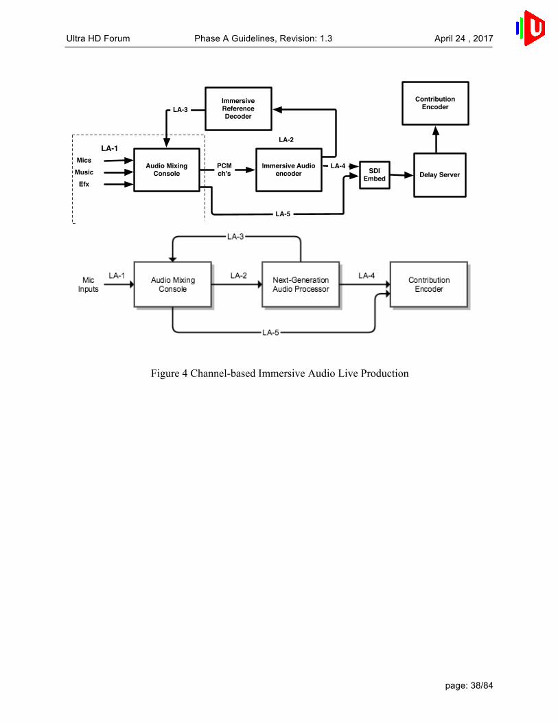
Ultra HD Forum Phase A Guidelines, Revision: 1.3 April 24 , 2017
page: 38/84
Figure 4 Channel-based Immersive Audio Live Production
Audio Mixing Console
Immersive Audioencoder
Contribution Encoder
MicsMusic
Efx
LA-1
LA-4
LA-5
ImmersiveReference Decoder
LA-3
Delay ServerSDIEmbed
LA-2
PCMch's

Ultra HD Forum Phase A Guidelines, Revision: 1.3 April 24 , 2017
page: 39/84
Reference Point
Content Creation Functions
Reference Point Description
LA-1 Audio Capture and mixing
Microphones are placed throughout the live venue. Microphone feeds are brought into the audio mixing console in the same fashion as 5.1 production. Sound elements are mixed into a final immersive program.
LA-2 Immersive Audio Authoring
Audio groups are created in the mixing console representing the immersive mix as channel-based (e.g. 5.1.2, 5.1.4, 7.1.4) audio6.
LA-3 Immersive Audio Monitoring
The Next-Generation Audio Processor renders the audio to 5.1.2, 5.1.4 or 7.1.4 speaker feeds and sends these feeds back to the audio mixing console for monitoring in the live mix environment.
LA-4 Immersive Audio Encoding
Atmos immersive program, encoded as EAC-3 is delivered as a 5.1 channel bitstream + parametric side-data (steering data) to the contribution encoder7 transported over either a MADI or SDI link.
LA-5 Legacy Audio Delivery
Stereo or 5.1 complete mixes may be created at the audio mixing console and delivered via traditional means.
In this channel-based immersive audio example, a Dolby Atmos enabled E-AC-3 encoder
generates a compressed bitstream containing 5.1 channels of audio that is backwards compatible with legacy E-AC-3 decoders. In parallel, the encoder generates an additional set of parameters (specified in ETSI TS 103 420 [33]) that are carried in the bitstream, along with the 5.1 audio, for use by a Dolby Atmos E-AC-3 decoder. The full Atmos decode process reconstructs the original channel-based immersive audio source from the 5.1 backwards compatible representation and the additional parameters. A typical immersive program can be encoded, for example, at 384-640 kbps total, thus fitting into existing emission scenarios.
6 The downstream Atmos Channel-Based Immersive emissions encoder, using E-AC-3 with
ETSI TS 103 420 will render a legacy 5.1 audio program. It is recommended to verify the rendered 5.1 audio program using a suitable Atmos E-AC-3 decoder in the monitor chain.
7 See Section 11.5 regarding backward compatibility.

Ultra HD Forum Phase A Guidelines, Revision: 1.3 April 24 , 2017
page: 40/84
7. Security
7.1 Content Encryption Digital content has always been exposed to illegal reproduction and illegal distribution. Various content protection technologies have been developed, involving different scrambling algorithms. Some of these algorithms, still in use, were designed more than 20 years ago and are no longer resistant to sophisticated attacks.
As a general rule, it should be considered that scrambling algorithms with key size less than 64 bits are not resistant to sophisticated attacks; in fact, the time needed to succeed in such attacks is measured in seconds not hours.
A well-known algorithm is Data Encryption Standard (DES), designed in the 1970’s, and referred as FIPS 46-3. It was withdrawn from the list of algorithms recommended by the US National Institute of Standards and Technologies (NIST) in May 2005.
Another well-known algorithm is DVB CSA, approved by DVB in 1994, and described in ETSI ETR 289. Its design was initially secret but was subsequently disclosed in 2002. Since then, many publications describe various attacks. In particular, the publication “Breaking DVB-CSA”, by Tews, Wälde and Weiner, Technische Universität Darmstadt, 2011 describes an implementation of such attack. This paper reveals that with very reasonable investment, DVB-CSA with a 48-bit key size (also known as DVB-CSA1) could be reversed in real-time.
Fortunately, DVB-CSA with a 64-bit key size (also known as DVB-CSA2) is still resistant against these attacks and is likely to remain so for another few years.
Content protection technologies are now using more recent scrambling algorithms with a larger key size, usually a minimum of 128 bits.
The algorithms that have been standardized for protection of digital content are: • B7 AES, Advanced Encryption Standard, published in FIPS-197, NIST, 2001, • B7 DVB-CSA3 published in 2011 by DVB in ETSI TS 100 289 V 1.1.1., • B7 DVB-CISSA published in 2013 by DVB and described in ETSI TS 103
127 V1.1.1 The Ultra HD Forum recommends the following regarding content security:
• B7 UHD Phase A content should not be scrambled with DVB-CSA1, nor with DES scrambling algorithms.
• B7 UHD Phase A content should be scrambled with AES or DVB-CSA3, using a minimum of 128 bits key size.
• B7 DVB-compliant service providers should use DVB-CSA3 or DVB-CISSA when transmitting Live or linear UHD Phase A content.
• B7 In the case where DVB-CSA3 is still not deployed, it is acceptable to use DVB-CSA2 with a crypto-period between 10 and 30 seconds, during the time needed to upgrade the equipment to DVB-CSA3.

Ultra HD Forum Phase A Guidelines, Revision: 1.3 April 24 , 2017
page: 41/84
7.2 Forensic Watermarking 7.2.1 Introduction
Forensic Watermarking complements content protection technologies such as Digital Rights Management (DRM) and Conditional Access Systems (CAS) by providing a means to deter piracy. In this case, Forensic Watermarking is used to generate individualized copies of a video asset thereby allowing the recovery of forensic information to address security breaches. For instance, such forensic information could identify the user receiving the content or the device receiving or displaying the content, its model ID, or other information that can help identify a piracy source.
A watermarking technology used for Forensic Watermarking is characterized by a number of properties, including:
• Fidelity: the modifications made to the content to introduce the Watermark Identifier shall remain imperceptible for a human being;
• Robustness: the Watermark Identifier shall be detectable after post-processing operations that may be performed by pirates, e.g., re-compression, camcording, screencasting, etc.
• Payload length: the size of the Watermark Identifier expressed in number of bits that can be inserted.
• Granularity: the duration of multimedia content that is needed for detecting a Watermark Identifier, usually expressed in seconds and dependent on the payload length.
• Security: the Watermark Identifier shall withstand targeted attacks from adversaries that know the Forensic Watermarking technology in use as well as its technical details.
The following sections provide: • Information about watermarking terminology, use cases and applications. • Consideration for performance, feasibility, privacy, and other aspects. • High level information flow for some use cases. • Communication specification for integration of Forensic Watermarking.
7.2.2 Use Cases
Forensic Watermarking is routinely used nowadays in professional environments, e.g., for distributing movies prior to theatrical releases and in Digital Cinemas. In 2014, MovieLabs released a specification [38] that mandates the use of Forensic Watermarking on UHD content. In this context, it is currently being considered at different stages of the content distribution pipeline. This section provides a comprehensive overview of these different stages and how different watermarks contribute to the forensic analysis. However, the remaining sections will only focus on the use case “Forensic Watermarking Identifying Consumers Devices.”
7.2.2.1 Forensic Watermark Identifying Operators It is common practice for content owners to incorporate a master Watermark Identifier in the copy of the movies that they are shipping to operators. It provides them with means to track

Ultra HD Forum Phase A Guidelines, Revision: 1.3 April 24 , 2017
page: 42/84
which resellers have been pirated in order to ask them to adopt relevant security countermeasures. Such master Watermark Identifiers are embedded in very high quality content and fidelity is therefore of paramount importance. In this case, fast turnaround processing time is not as critical as in other application use cases. The watermark embedding process can be performed offline and watermark detection results can be returned after a few days.
7.2.2.2 Forensic Watermark Identifying Redistribution Networks An operator may distribute content through several channels: satellite, terrestrial broadcast, over-the-top, etc. These redistribution channels can be part of the operator’s own redistribution network. They may also be operated by some affiliate networks, and in such a situation, when piracy is detected to originate from an operator, there is some uncertainty about the source of the leak. To disambiguate the situation, alternate Watermark Identifiers can be embedded for the different redistribution channels. In this context, fast detection is usually not required. On the other hand, watermark embedding may need to be performed on-the-fly to accommodate redistribution of some video content, e.g., live broadcast.
7.2.2.3 Forensic Watermark Identifying Consumers Devices The MovieLabs specification [38] requires identification to stop leakage on the level of device or device type. This is expected to provide means to analyze piracy at the finest granularity in order to deploy targeted anti-piracy measures accordingly. Based on this requirement for premium content, it is likely that Forensic Watermarking could be useful to help deter piracy of live events such as sports and music concerts.
The live service application use case has stronger requirements, as the watermark embedding operation must not introduce significant delay in the content transmission chain. In addition, it may be even more critical to quickly identify the source of an illegal retransmission in order to stop it, ideally before the end of the pirated live program such as a sporting event. On the other hand, the watermark fidelity constraint might be relaxed on some occasions to speed up the detection process. Finally, while it is important to secure the Watermark Identifiers against malicious attacks, the attacker will have more time to execute attacks on VOD content than live content, which quickly expires in value even in pirated form.
7.2.3 Distribution
For Forensic Watermarking that is identifying consumers’ devices, different methods of media distribution may result in different workflow and process optimizations.
• Physical and Broadcast Distribution: The content is distributed either via physical media such as a Blu-ray disc or via broadcast.
• File Distribution: A single file is made available for playback, used in environments with guaranteed bandwidth streaming, or (progressive) download.
• ABR Streaming: Streaming without guaranteed bandwidth but adaptation to the available bandwidth is done based on several available bandwidth options made available in a manifest or playlist.
The distribution mechanism has impacts on the integration of the watermarking system. Sections 7.2.4 and 7.2.5 present in detail two major approaches, namely those that operate in a single step (one-step) and those that require a preprocessing step (two-step). In addition to the distribution mechanism, the selection of one-step versus two-step watermarking is guided by

Ultra HD Forum Phase A Guidelines, Revision: 1.3 April 24 , 2017
page: 43/84
other aspects such as the integration complexity, the availability of client-side marking capabilities, the ability to modify components on the head-end side, etc.
7.2.4 One-Step Watermarking
This approach to create forensically watermarked content is to mark decompressed baseband video content in a single step:
• During encode on the server, or
• During playback in the secure video pipeline. One-step watermarking on the distribution server side requires delivering individualized
watermarked content to every device requesting it. As such, it may not be suitable for serving a large number of recipients due to scalability constraints when encoding a stream for each recipient.
One-step watermarking is therefore usually applied on the client side, where the watermark is enabled. It typically involves communication between the Conditional Access (CA) and the watermarking (WM) modules as shown in Figure 5.
Figure 5 One-Step watermark performed on the client side
7.2.5 Two-Step Watermarking
7.2.5.1 Introduction This approach consists of decomposing the watermarking process into two steps: one step to precompute different Variants for different parts of the video asset and a second step to compose a unique combination of Variants to encode the desired Watermark Identifier. The underlying objective is to separate computationally intensive tasks in the preprocessing step to obtain the lightest and fastest possible watermark embedding process.
• Step #1: preprocessing. The preprocessing step computes Sets of Variants for an input video content. Variants are generated by analyzing the video content, typically frame-by-frame, either in the baseband domain (prior to encoding) or in the encoded domain (post encoding). Eventually, this preprocessing step yields Sets of Variants
(WM) Watermark Embedder
(CA) CAS or DRM client
Initialization & configuration
Content
Middleware or player
Watermarked Content
Initialization

Ultra HD Forum Phase A Guidelines, Revision: 1.3 April 24 , 2017
page: 44/84
that can be applied to the encoded and possibly encrypted content in the second step. This step is performed once per input video content.
• Step #2: watermark embedding. The watermark embedder has access to a Watermark Identifier that is used to generate a unique Variant Sequence (Variant Sequence Generator), by selecting for each Set of Variants a single Variant. This Variant Sequence is part of the final forensically watermarked video content that may comprise unaltered segments of video. This operation can be performed in transit (e.g., in a network edge) or in the client device (e.g., during playback or PVR recording).
Figure 6 Two-step watermarking
Two-step embedding enables server side embedding that creates requirements on the server such as VOD server or CDN edge, but is transparent to the client. It alternatively enables embedding on the client before decoding.
7.2.5.2 Preprocessing for Baseband Content For the first step, the watermark preprocessor provides Variants of the baseband content to the video encoder. The resulting Sets of Variants are then encoded and packetized in a relevant container for transport.
Figure 7 Watermark preprocessing in the baseband domain for two-step
watermarking
7.2.5.3 Preprocessing for Encoded Content For the first step, the analysis of the content is performed on the encoded bitstream. The watermark preprocessor is fed with the encoded video content produced by the encoder and then generates Sets of Variants.
Set of Variants #2 Set of Variants #1 Set of Variants #3
Variant A Variant B
Variant A Variant A Variant B
Variant C Variant B
Segments of video left untouched
Segments of video with several Variants. Only one (highlighted) is kept depending on the Watermark Identifier
Content File
Playback Timeline

Ultra HD Forum Phase A Guidelines, Revision: 1.3 April 24 , 2017
page: 45/84
Figure 8 Watermark preprocessing in the encoded domain for two-step
watermarking
Such a preprocessing module can operate completely independently of the encoder. However, for latency-constrained applications (e.g., live broadcast), it may be desirable to have a more intimate integration to minimize processing delay.
7.2.5.4 Watermark Embedding The watermark embedding (second step) process comprises:
• A Variant Sequence Generator (VSG) that selects a single Variant from each Set of Variants and thus produces a Variant Sequence that encodes the desired Watermark Identifier (WM ID), and
• A Watermark Embedder (EMB) that applies the selected Variant to the compressed video bitstream in order to obtain a Variant Sequence, which is a video watermarked with a unique identifier.
If the Variant data is applied in independent encryption blocks, they may be applied in the encrypted domain without knowledge of the decryption key.
The VSG receives Set of Variants in a relevant container. Based on the Watermark Identifier, it produces a Sequence of Variants, and the EMB applies them to the bitstream to generate a watermarked video. This sequence can be decoded for rendering, stored for later use (PVR), or forwarded further along the transmission pipeline.
Figure 9 Watermark embedding, second step of two-step watermarking
7.2.5.5 Deployment Deployment modes differ in the time and location of the embedding step (second step) that is
dependent on integration preferences and network types. Just in Time Server Embedding The server hosts the Sets of Variants computed in the preprocessing step and possibly also
(parts of) the original content. Using information provided by the client with the content
Head-end
Encoder WM Preprocessor
Variant metadata binding

Ultra HD Forum Phase A Guidelines, Revision: 1.3 April 24 , 2017
page: 46/84
requests, the server associates a Watermark Identifier to the request. The VSG can then operate and the EMB delivers watermarked content of video to the requesting client.
The identification of a session or client may be done with known authentication methods such as HTTP cookies, tokens or authenticated sessions.
Prepared Server Embedding This is similar to the above, but embedding is applied before a content request is made and a
stack of pre-computed watermarked video segments is created that are served to the client when requested.
If the entire file is marked with a unique number, the next file is taken from the stack and a record is kept, indicating the link of the session to the Watermark Identifier.
If the segments are pre-marked, e.g., in the case of ABR content, they are chosen individually for each request.
ABR Playlist Embedding This approach is similar to the above, in that it is using pre-marked segments, but here, a
server provides an individualized manifest or playlist that tells the client what segments to download. For this, the playlist server personalizes the manifest so that each client only ‘sees’ segments that encode its Watermark Identifier. When consuming the playlist, the client requests Variant segments (encoding its Watermark Identifier) that are served by a streaming server that hosts all pre-computed Variant segments. This requires playlist entries that are not templated, but have segment granularity such as HLS or DASH.
Figure 10 ABR playlist embedding
Client Device Embedding Here, the client device receives the Sets of Variants and content required to create differently
marked variations. Using the Watermark Identifier of the device, the VSG produces a Variant Sequence that is then used by the EMB to produce a watermarked video bitstream to be forwarded to the video decoder. To secure the embedding, the embedder shall operate in a secure environment, e.g., in the trusted execution environment along the secure video path.
Another security mechanism includes controlling access to variants with decryption keys. This approach is particularly useful for scenarios where individual stream delivery is not feasible, such as one way distribution, including physical media.
7.2.5.6 Variants Transport Mechanisms
ABR Encoder
WM Processor
Device
Every segment has two versions in the CDN, one watermarked with 0 and one watermarked with 1
Playlist generator
1. Get a dedicated playlist computing
its WM ID 2. Get only the segment referenced by the playlist

Ultra HD Forum Phase A Guidelines, Revision: 1.3 April 24 , 2017
page: 47/84
The steps of pre-processing and watermark embedding operations are unlikely to be co-located. It is therefore necessary to define a mechanism to transport the Sets of Variants along with the content to be watermarked. A first challenge to address is the temporal synchronization between the video content and the Variants metadata, e.g., to support trick play. Depending on the implementations, the transport mechanism may also define which portion of the Watermark Identifier applies to a given Set of Variants.
Transport at the Media Layer Variants metadata can be incorporated at the media layer. For instance, MPEG standards
indicate that any proprietary information can be placed in the video bitstream as dedicated NALUs referred to as Supplemental Enhancement Information (SEI). Variants SEI NALUs can be signaled using a dedicated identifier [25], [26].
The advantage of such a low-level transport mechanism is twofold. First, the Variants metadata is finely interleaved with media essence, thereby providing the necessary temporal synchronization between the content and the Variants metadata. Second, Variants metadata can inherit the protection provided by CAS or DRM systems. On the other hand, such low level signaling may require integration along the secure video path and/or the trusted execution environment, which requires collaboration from chip vendors for adoption.
Figure 11 Transport at the media layer using MPEG SEI NALUs
Out-of-Band Transport Transporting Variants metadata at the media as well as container layer requires some level of
video parsing. However, in some integration scenarios, such a requirement may not acceptable, e.g., for scalability reasons or because parsing is impossible at the integration point due to encryption. In such a situation, it is desirable to have a direct access to the Variants metadata either with a separate file containing the metadata itself or with a separate file containing relevant pre-computed parsing information to access the Variants metadata directly in the video file without performing the actual parsing. This is typically the case on a CDN edge server.
A CDN edge server serves video segments on request to clients, among other things. To guarantee the scalability of the service, it is of the utmost importance to reduce parsing to a minimum. A possible solution is to store Sets of Variants in the container in such a way that one of the Variants can be selected simply by skipping the data of the other Variants. The indices of where the Variants are located in the stream can then be stored in a separate file, which can be loaded into memory by the CDN edge server. As a result, the server can perform the watermark embedding operation directly without any video parsing.
Packetized Elementary Streams containing all NALUs corresponding to a frame
SEI NALU containing Variants metadata that shall be applied to the next slice NALUs contained in the same PES
Individual NALUs
(SPS, PPS, slice,etc)

Ultra HD Forum Phase A Guidelines, Revision: 1.3 April 24 , 2017
page: 48/84
8. Real-time Program Service Assembly
Real-time Program Services consist of a linear, pre-scheduled stream of content that is assembled in real-time for distribution to consumers such as a broadcast television channel, a cable network, etc. Real-time Program Services are comprised of Live and/or Pre-recorded content and may also include graphic overlays, such as station logos, emergency text crawls, etc.
A Real-time Program Service may be assembled at one or more locations. At Production, graphics and slow motion replays may be added to Live content. At the Broadcast Center and Service Provider, interstitials, logos, news or emergency alert crawls, etc. may be combined to produce the final product delivered to the consumer. It is also possible that assembly can occur at the consumer device, such as for targeted advertisements and rendering closed captions.
8.1 Maintaining Dynamic Range and Color Space Parameters
Different dynamic range and color spaces should not be mixed in a Real-time Program Service. For example, service operators should not shift between HLG10, PQ10 or SDR/BT.709. Decoders require time to adjust to different encoded data settings – as much as 2 seconds or more has been observed by Ultra HD Forum members – causing a poor consumer experience. OTT providers offering ABR streams must also ensure that the adaptive bitrate streams are all of the same transfer curve and color space8. Similar to the linear progression of a program through time, the progression of rendering successive levels of ABR streams requires quick adjustments on the part of decoders. If a Real-time Program Service must contain a switch point between dynamic range and color space, it is recommended that such switches be performed overnight or in a maintenance window and black frames be inserted at switch points to allow decoders and viewers to adjust to the new content characteristics.
It is possible to remap SDR/BT.709 content into HLG10 or PQ10, to up-convert SDR/BT.709 content to HLG10 or PQ10 and vice versa, and to convert content from PQ10 to HLG10 or vice versa. The following subsections offer guidelines for normalizing content in the headend for this purpose. See also Section 11 for conversion possibilities in consumer equipment for backward compatibility.
8.2 Conversion from SDR/BT.709 to PQ10/HLG10 In multiple areas of the production chain, it is anticipated that a requirement exists to “mix” or “switch” SDR/BT.709 sources and PQ10/HLG10 sources when constructing a Real-time Program Service. Mixing of this kind may take many forms as it does today in SDR only environments (practicing BT.1886 [4] gamma and BT.709 [2] color space). To make it possible 8 See “Guidelines for Implementation: DASH-IF Interoperability Points v3.3”, Section 6.2.5,
which is a work in progress as of 2016, but may be found at http://dashif.org/wp-content/uploads/2016/06/DASH-IF-IOP-v3.3.pdf for reference.

Ultra HD Forum Phase A Guidelines, Revision: 1.3 April 24 , 2017
page: 49/84
to combine such elements, SDR/BT.709 sources must be converted into the PQ10/HLG10 domain with respect to both an industry compliant transfer function (e.g., BT.2100 [5] HLG, ST 2084 [8] PQ) and color space (i.e., BT.709 [2] primaries “mapped” into the BT.2020 [3] container). Such conversions can utilize:
• Remapping: SDR/BT.709 content is decoded and repackaged as PQ10 or HLG10 containers, but while changing the color space, remapping does not change the color gamut or the dynamic range of the content; the content is simply mapped across to the equivalent color and brightness values.
o When remapping SDR to HDR for PQ and HLG, the level of reference white should be considered. Reference white in SDR content is typically about 90 IRE, leaving very little headroom for speculars. In the case of HLG, the BBC and NHK recommend the reference level for HDR graphics white (aka “reference white”) be set to 75 IRE (equivalent to 203 cd/m2 on a 1,000 cd/m2 reference display, or 343 cd/m2 on a 2000 cd/m2 reference display). This was chosen as it leaves sufficient headroom for “specular highlights” and allows comfortable viewing when HLG content is shown on HDR/WCG and SDR/WCG displays..
• Up-conversion: SDR/BT.709 is decoded and then enhanced/modified to emulate PQ10/HLG10 and repackaged as above. Blind (not supervised) up-conversion can lead to undesirable results depending on the technology so care should be used and any algorithms or equipment should be carefully evaluated.
Each method has particular advantages and disadvantages, and one or the other may be
preferable under different circumstances. If the service provider intends to simulcast the UHD Phase A service in SDR/BT.709 for backward compatibility, then remapping may be preferable, because content that was originally SDR/BT.709 will remain exactly as intended in the legacy version of the service. Conversely, the service provider may prefer that all the segments of the Real-time Program Service look as uniform as possible to ensure a consistent consumer experience, and thus up-conversion may be appropriate. For example, up-conversion may be preferred for Live production mixing SDR/BT.709 and PQ10/HLG10 cameras, high quality SDR content, and legacy content like advertisements.
Under some circumstances, (e.g. viewing in a darkened room) HDR displays and content can cause discomfort if consideration is not given to the viewer’s vision adapting to the average light level on the screen at any given moment. For instance, if a feature program has a low average light level such as a night scene and the picture abruptly cuts to a high average luminance scene in an interstitial, the viewer may experience discomfort similar to that experienced with changing light conditions in nature. When advertisements are inserted into content, consideration should be given with respect to transitions from dark to light.
The described conversions typically will be performed by dedicated devices using a combination of 1D and 3D LUTs or other appropriate algorithms or technology. Devices of this type may be used for both SDR/BT.709 to PQ10/HLG10 or vice versa as the production and the capability of the equipment in use requires.
A real-time dedicated conversion device is essential for some use cases, which may be encountered throughout the production chain, such as:
• Mix of SDR/BT.709 and PQ10/HLG10 live sources Broadcasting live events (typically sports) in PQ10/HLG10 may require a relatively

Ultra HD Forum Phase A Guidelines, Revision: 1.3 April 24 , 2017
page: 50/84
high number of cameras and it is probable that all these cameras will not be HDR-capable. In that situation, SDR/BT.709 cameras can be utilized if the conversion process is implemented either at the output of the SDR/BT.709 camera or at the input of the mixer.
• SDR/BT.709 interstitials in a PQ10/HLG10 program With SDR/BT.709 interstitials, the interstitial content will likely come from a playout server. In this case the conversion process has to be implemented either at ingest, at the output of the playout server, or at the input of the mixer.
• Use of SDR/BT.709 content Extensive libraries of SDR/BT.709 content may be used, for example a live sports match production that includes archive footage from previous matches; such material needs to be converted to PQ10/HLG10 (using a near real-time file-to-file converter) before entering the video pipeline
Figure 12 Sample Live Workflow with Mixed Format Source Content
Converting content to a common set of HDR and WCG technologies may occur at different points in the workflow from Production to the Consumer premises.
At the Production stage, multiple versions of the content may be produced. In the case of Pre-recorded content, producers have the opportunity to create multiple versions of the content applying creative judgement to each version. This is recommended for all Pre-recorded content and especially for interstitial material that may be inserted into a variety of Real-time Program Services, which may be operating with different HDR/WCG configurations. Live content may also be output in multiple formats; however, time constraints may prevent highly detailed artistic input. Automated conversion technologies can be “tuned” by the content creator to make the conversion the best it can be for the given program.
At the Broadcast Center or Service Provider stage, content may be converted to the provider’s chosen HDR/WCG configuration using automated tools. This may not include program-specific creative input; however, professional equipment may produce acceptable results.
Ultra HD Forum Phase A Guidelines, Revision: 1.3 April 24 , 2017
page: 51/84
At the consumer premises, color volume transform may be possible for the purpose of backward compatibility (with limitations, see Sections 10 and 11). Also, display devices may “map” content internally to best suit the display characteristics. Both of those processes operate on a content stream with one, constant dynamic range and color space. Real-time Program Service providers should not expect consumer equipment to render seamless transitions between segments of content that have different transfer function or color spaces.
8.3 Conversion between Transfer Functions A receiver may not be able to switch seamlessly between HDR transfer functions; therefore, it is recommended that only one transfer function be used for a given Real-time Program Service in Phase A. This section offers guidelines to service providers to convert HDR content from PQ10 to HLG10 or vice versa in order to maintain a single transfer function in the service.
8.3.1.1 PQ10 to HLG10 It is possible that Pre-recorded programs will be produced in PQ10 in Phase A; however, some service providers may favor HLG10 delivery for its degree of backward compatibility. It is possible to perform the required conversion with a LUT. As the PQ program may have pixel values as high as 10,000 nits, some color volume transform of highlights may occur in content converted from PQ10 to HLG10 and then rendered on a lower peak luminance display.
8.3.1.2 HLG10 to PQ10 It is possible that Live programs will be produced in HLG10 in Phase A; however some service providers may favor PQ10 delivery making it necessary to convert HLG10 encoded content into PQ10. This conversion can be accomplished with a static or programmable LUT prior to encoding. It must be considered that this conversion involves translation from a scene-referred relative signal to a display-referred absolute signal. As such, a target peak luminance needs to be preset as part of the LUT conversion function. At the time of this writing, grading monitors typically have a peak brightness of 1,000 nits so that value may be used; i.e., the maximum value of the HLG signal would map to the PQ value of 1,000 nits.
8.4 Conversion from PQ10/HLG10 to SDR/BT.709 This operation is needed for PQ10 and HLG10. This method may be employed at the headend prior to final distribution to provide a backward compatible feed to legacy 2160p/SDR/BT.709 TVs9 and legacy HD networks. (See also Section 11 on Format Interoperability including STB conversions.)
9 Although HLG offers a degree of backward compatibility with SDR/WCG displays, there is no
evidence that HLG offers backwards compatibility for BT.709 [2] displays without additional processing as described in this section. However, both DVB and ARIB require support of BT.2020 color space (and HDMI 2.0) in legacy 2160p/SDR TVs, so it may be reasonable to expect that many of these units are BT.2020-compatible, and thus able to render HLG content.

Ultra HD Forum Phase A Guidelines, Revision: 1.3 April 24 , 2017
page: 52/84
It is possible to do this conversion using a 3D LUT mechanism as described in Section 8.2. Another method is an invertible down-conversion process described in ETSI TS 103 433 [32], in which HDR/WCG content is down-converted in real time to SDR/BT.709 at or prior to the emission encoder (see also Annex E 17). As a commercially deployed system in 2016, this down-conversion process is considered to be a Phase A technology.

Ultra HD Forum Phase A Guidelines, Revision: 1.3 April 24 , 2017
page: 53/84
9. Distribution
This section describes the various stages of distribution for a UHD Phase A workflow. It shows the primary nodes and distribution paths in a typical workflow and describes each node and interface in the chain.
Figure 13 Distribution Nodes and Interfaces
Table 7 Compression and Distribution Nodes and Interfaces
Production Content production location, e.g., studio, live venue truck, etc. EC-1 Compression/distribution from Production to a central location Broadcast Center, Network A central location such as a broadcast network where content
is aggregated for further distribution to station affiliates or service providers; this node is often used in distribution of Live content
EC-2 Compression/distribution to the final point before distribution to consumers
Station, MVPD, OTT Provider A service provider that distributes content to consumers, e.g., a local television station affiliate, an MVPD or an OTT service provider; this node also often produces Live content, such as news programming
EC-3 Compression/distribution to the consumer device Consumer The viewer device, such as a television set, tablet, PC, STB
connected to a display, etc. Some workflows may be simpler, with only three nodes (production, service provider and
consumer) while others may be more complex with more than 4 nodes in the chain. The concepts that encompass a four-node workflow can largely be applied to both simpler and more complex scenarios.
The workflows described include those in use in 2016. The workflows described will be able to carry metadata except where noted otherwise. The workflows apply to Real-time Program Services and to On Demand content that was originally offered as Live content.
Typical distribution practices involve decoding, modification and re-encoding the content as it flows from production to consumer. Carriage of transfer function, color container, color matrix, and optional HDR10 static metadata is possible in HECV encoding, but not in SDI interfaces. For this reason, when content is decoded at a node, modified, and then re-encoded, attention must be given to preserving this data so that it can be re-inserted at each encode step.

Ultra HD Forum Phase A Guidelines, Revision: 1.3 April 24 , 2017
page: 54/84
Audio and caption/subtitle are not expected to differ from those used in HD content distribution, and thus are not expected to require the same attention. For pre-recorded content, embedded test patterns at the head or tail of the program can be useful for verifying accurate signaling.
The next update to the Guidelines document (Phase B), describing technologies mature enough to deploy in 2017, is expected to have significant changes to the audio workflow, as the Next-Generation Audio (NGA) systems begin to be used commercially. For 2016, audio is expected to follow workflows established for Dolby-E and PCM in contribution applications, and AC-3, E-AC-3, HE-AAC, and AAC-LC as the 5.1 emission codecs.
Captions and subtitles are expected to follow workflows established for CTA 708/608, ETSI 300 743, ETSI 300 472, SCTE-27, and IMSC1 formats. HEVC [26] includes provisions for carrying captions and subtitles in the VUI and SEI in a similar manner to legacy video codecs.
In Phase A the production system will likely be SDI-based (1x12G or 4x3G) and therefore deployment of an SDI workflow is likely. In the future, an IP-based workflow should be implemented, using techniques such as Media over IP: ST 2022-6 and near-lossless compression technologies such as VC-2 (Dirac), JPEG 2000, or other vendor proprietary solution.
Methods of carrying 2160p over SDI defined by SMPTE are shown in Table 8 below.
Table 8 SDI Input Standards for 2160p Content
Interface Standard Details Notes 4x 3G-SDI* SMPTE ST 424 4 quadrants of 3G-SDI
SMPTE ST 425-1 3G-SDI source input format mapping (Level A and Level B)
2 options: quad split or 2 sample interleave
1x 12G-SDI SMPTE ST 2082 12Gbps SDI native * For 1080p, only 1x 3G-SDI is needed. As of publication of this document, metadata for HDR10 cannot be carried over SDI. If
HDR10 format is used instead of HLG10 or PQ10, metadata should be applied at the video encoder as follows:
• In compressed format, HEVC, Main 10 Profile, Level 5.1 may be used for metadata signaling. The metadata is carried via VUI and SEI messages (see Section 6.1.8).
• In a “light compression” format, such as a 12G-SDI signal mapped into a 10GbE, there are multiple options including VC-2 (Dirac), JPEG 2000, and other vendor proprietary solutions.
For UHD Phase A content, only uncompressed video over SDI (4x 3G-SDI or 1x 12G-SDI) or compressed video using HEVC, Main 10 Profile Level 5.1 is recommended for Phase A workflows.
9.1 Production Processing and Contribution This section describes processes for transmitting UHD Phase A content from an event venue or production studio to a central facility such as a broadcast center or network. Note that in some cases the content may be distributed to more than one broadcast center, and different facilities

Ultra HD Forum Phase A Guidelines, Revision: 1.3 April 24 , 2017
page: 55/84
may have different standards or requirements for content acquisition. For example, an international sports event program may be transmitted to a broadcast center, which in turn distributes the program to broadcast stations in different countries, which may have different format requirements, e.g., frame rate.
Figure 14 Contribution Workflow
In the case of Live content, the first stage is either a truck or remote production gallery, equipped with a production switcher, camera racking equipment, graphics and audio mixing. The production switcher typically will be receiving baseband signals from cameras and other sources such as digital disc recorders (DDRS) or other playback devices. The Technical Director (vision mixer) in the truck then applies transitions, lower thirds, etc., and may splice in Pre-recorded content (slow motion, interviews, match analysis, etc.). See Section 6.3 for details on Live content production and Section 8.2 for details on mixing source content of different formats in a Live program production.
In the case of Pre-recorded content, the studio has the opportunity to apply post-production edits. See Section 6.2 for details on Pre-recorded content production.
9.1.1 Video
It has been tested and confirmed by several Ultra HD Forum member companies that in the content production part of the chain, HLG10 and PQ10 can be used with 10-bit 4:2:2 workflow methods and equipment available in 2016. However, at this stage of technology development

Ultra HD Forum Phase A Guidelines, Revision: 1.3 April 24 , 2017
page: 56/84
(i.e., 2016) such productions may require non-commercially-deployed prototypes and/or workarounds.
Examples of image processing functions can include mixes, wipes, fades, chroma-keying, linear or luma-keying, motion tracking, DVE moves, slow motion, freeze frames, addition of graphics tickertapes or logos, use of virtual sets, etc. Since image processing may occur many times before final delivery to the consumer, this can be particularly important for Live programming, in which much of the workflow must be fully automated.
Once the content is ready, it is sent to a contribution encoder. Live production workflows typically feed a modulated uplink to a satellite that delivers the content to a broadcast center or network. In some cases, fiber will be used as well as or instead of a satellite. For cost and bandwidth reasons, the satellite feeds will be compressed.
A 2160p feed may be compressed in HEVC, Main 10 Profile, 4:2:0 or 4:2:2 or quadrant-based in 4x1080p in AVC 10-bit 4:2:2. A 1080p HDR/WCG feed may be compressed in either HEVC, Main 10 Profile, 4:2:0 or AVC 10-bit 4:2:2. Note that when fiber links are used, intra-frame encoding and decoding, such as JPEG 2000, may be used. The HDR transfer function and color space must be predetermined and used uniformly for the production.
The satellite operator decodes the signal back to baseband using an IRD (integrated receiver decoder).
As of 2016, quadrant based (4x1080p 4:2:0 or 4:2:2 10-bit) encoding/decoding is commonly used to create a 2160p image. AVC, AVC-I and JPEG 2000 all could be used for the quadrant codec. In the case that quadrant streams are sent, 4 encoders and 4 IRDs are synced. Single frame 2160p solutions using HEVC are likely to replace quadrants over time as they offer better compression efficiency (HEVC vs. AVC and single frame encoding) and are simpler to operate. It is expected that this 2160p HEVC contribution method will be deployed in Phase A.
AVC, HEVC and JPEG 2000 differ in the expected bitrate of the contribution file and in the mechanism for carrying HDR/WCG signaling.
Approximate examples of the contribution bandwidth required and HDR carriage signaling are shown below:
Table 9 Contribution Bitrates and Key Parameters
Source Contribution Format HDR/WCG Carriage Signaling
Approximate Typical Bitrate Range
1080p 50/60 fps
AVC 4:2:2 10-bit Under definition in MPEG 20 – 50 Mbps HEVC, Main 10, Level 5.1 4:2:2/4:2:0
As per MPEG VUI/SEI signaling [26]
10 – 40 Mbps
JPEG 2000 Not standardized 100 – 150 Mbps 2160p 50/60 fps
AVC 4:2:2 10-bit (4 quadrant)
Under definition in MPEG 90 – 140 Mbps total
HEVC, Main 10, Level 5.1 4:2:2/4:2:0
As per MPEG VUI/SEI signaling [26]
50 – 80 Mbps
JPEG 2000 Not standardized 450 – 550 Mbps

Ultra HD Forum Phase A Guidelines, Revision: 1.3 April 24 , 2017
page: 57/84
The Ultra HD Forum offers these bitrates based on the general experience of its members. It is important to note that the actual contribution bitrates can vary substantially from the figures shown depending on many factors, such as latency, quality of source content, type of source content, type of network, multi-hop contribution, etc.
In Phase A, the main factor affecting contribution bitrates is the step between 1080p and 2160p spatial resolution; the addition of HDR or WCG has a much smaller impact. HDR and WCG do, however, require 10-bit encoding precision and modifications to the signal that, if not maintained, will ‘break’ the overall performance of the system resulting in an unacceptable image.
9.1.2 Audio
The next update to the Guidelines document (Phase B), describing technologies mature enough to deploy in 2017, is expected to have significant changes to the audio being delivered to the home, as the Next-Generation Audio (NGA) systems begin to be used commercially.
In Phase A, production practices for audio are not expected to differ from those used in current HD content creation. In Phase A audio is expected to follow multi-channel workflows established for 5.1 surround and Dolby Atmos for delivery using one of the following emission codecs as appropriate for contribution applications: AC-3, E- E-AC-3, HE-AAC, or AAC-LC.
9.1.3 Closed Captions and Subtitles
Similarly, production practices for closed captions and subtitles are not expected to differ from those of HD content creation in Phase A. Closed captions and subtitles follow workflows established for CTA 608/708, ETSI 300 743, ETSI 300 472, SCTE-27, or IMSC1.
9.2 Broadcast Center Processing and Primary Distribution
This section describes the processes and functions involved in transmitting content from a central facility such as a broadcast center or network to a service provider such as an MVPD or OTT provider. (UHD Phase A terrestrial broadcasts are not expected in 2016.)
In the broadcast center, PQ10 or HLG10 signals can follow roughly similar workflow methods as those used for HD programming during image processing operations using a presentation switcher.
The output of the primary distribution encoder will go to a MVPD or OTT provider that will typically decode the content, modify it, and re-encode it to the final distribution format.
There are multiple transport mechanisms possible for primary distribution to the MVPD or OTT service provider:
• SDI • IP that will carry MPEG -2 Transport Stream • IP that will carry DASH (OTT delivery) • Satellite delivery for both live linear and file transfer
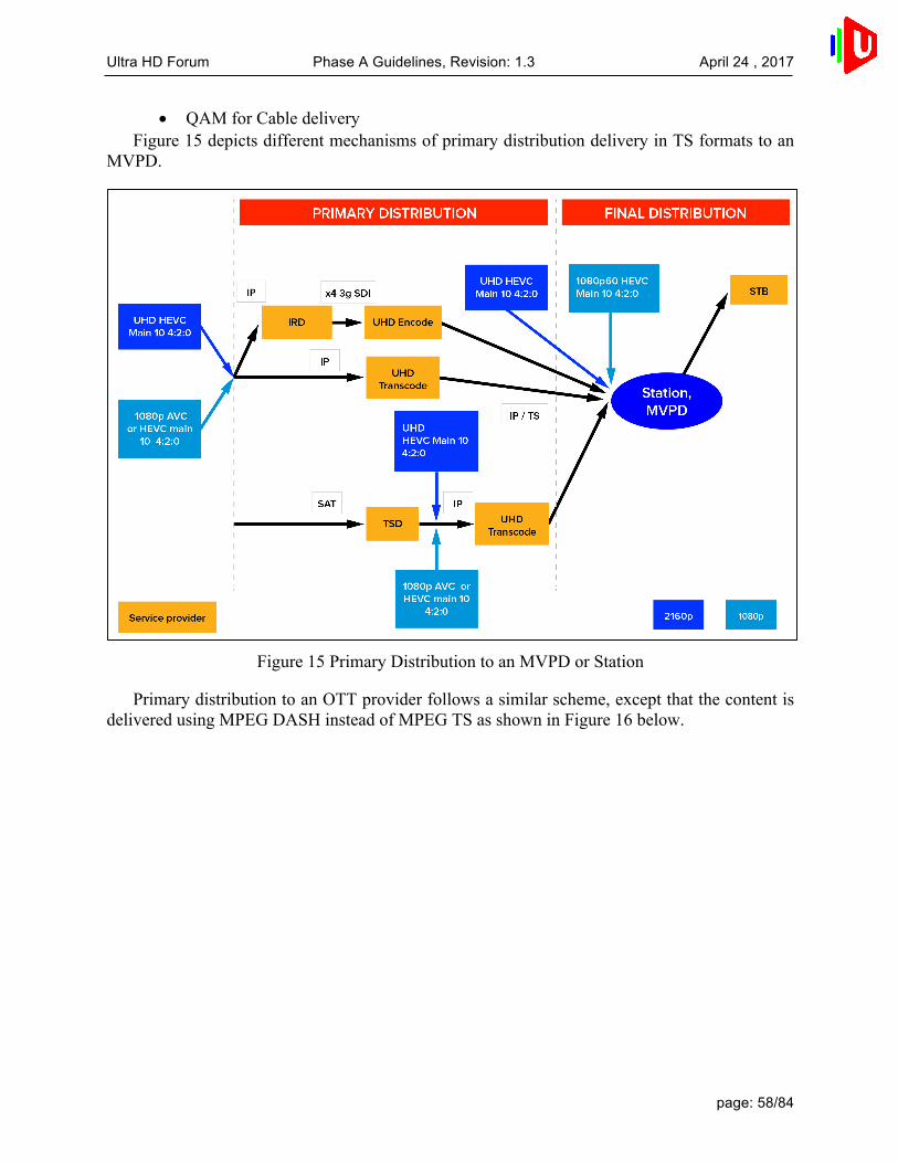
Ultra HD Forum Phase A Guidelines, Revision: 1.3 April 24 , 2017
page: 58/84
• QAM for Cable delivery Figure 15 depicts different mechanisms of primary distribution delivery in TS formats to an
MVPD.
Figure 15 Primary Distribution to an MVPD or Station
Primary distribution to an OTT provider follows a similar scheme, except that the content is delivered using MPEG DASH instead of MPEG TS as shown in Figure 16 below.

Ultra HD Forum Phase A Guidelines, Revision: 1.3 April 24 , 2017
page: 59/84
Figure 16 Primary Distribution to an OTT Provider
Primary distribution encoding to affiliates or other partner organizations is expected to be 4:2:2 or 4:2:0 10-bit. Note that frame rate (temporal) conversion may be required for international distribution.
For Live content, the production of the signal may be done via a live ingest server and playout server whose output will be SDI (1x12G or 4x3G or 1x3G in the case of 1080p content). The signal encoded by the primary distribution encoder should be HEVC, Main 10 Profile, 10-bit depth [26].
Table 10 describes the formats that can be used for primary distribution transmission.
Table 10 Primary Distribution Bitrates and Key Parameters
Spatial Resolution Primary Distribution Format
HDR/WCG Carriage Signaling
Approximate Typical Bitrate Range
1080p HEVC Main 10 Profile, 10-bit [26]
VUI/SEI signaling [26]
10-20 Mbps
2160p HEVC Main 10 Profile, 10-bit [26]
VUI/SEI signaling [26]
40-50Mbps
Like contribution bitrates, the typical bitrates shown for HEVC 2160p are early
approximations only based on the general experience of Ultra HD Forum members; primary

Ultra HD Forum Phase A Guidelines, Revision: 1.3 April 24 , 2017
page: 60/84
distribution bitrates depend on many factors, such as latency, the quality of the source content, type of source content, type of network, etc.
9.3 Final Distribution from MVPD/OTT Provider Processing
This section describes image processing that may occur at the MVPD or OTT provider and the encoding, multiplexing and packaging required to prepare content for final distribution to consumers.
The MVPD or OTT Service Provider receives the Primary Distribution feed from the broadcast or network center. In many cases, the Service Provider will decode the signal and re-encode it for final distribution to the consumer.
9.3.1 Bit Depths
The below table illustrates bit depths in use in 2016.
Table 11 Existing Practices for Real-Time Program Service Distribution Formats
Case Bit Depth Color Gamut
Peak White at D65
Color Container
HDR Use Case
1 8 BT.709 100 BT.709 No Deployed 2 10 BT.709 100 BT.709 No Deployed 3 10 Up to
BT.2020 100 BT.2020 No DVB UHD-1, Phase
1 Scenario 4 10 Up to
BT.2020 Up to 10,000
BT.2100 Yes Phase A Guidelines
The Ultra HD Forum finds that Case 2 has not been widely deployed and may be phased out
quickly. Only Cases 3 and 4 are recommended for Phase A UHD services, and Case 4 is preferred. Cases and 1 and 2 are included for context.
In Cases 3 and 4, SMPTE ST 2086 can be used to signal Peak White. It should also be noted that in Cases 3 and 4, the color gamut can be up to BT.2020 color primaries; however, in current practice the gamut does not exceed DCI P3 primaries.
9.3.2 Video
In this final part of the chain, image manipulation may still be needed for ad insertion, ‘squeeze & tease’, channel logo insertion, etc. PQ10 or HLG10 can again follow roughly similar workflow methods as used for HD programming as they require only signaling describing the transfer function and color space.
HEVC Main 10 Profile, 10-bit [26] is recommended as the only final distribution or emission codec as shown in Table 12 below, as all UHD decoders support HEVC.

Ultra HD Forum Phase A Guidelines, Revision: 1.3 April 24 , 2017
page: 61/84
Table 12 Final Distribution Bitrates and Key Parameters
Spatial Resolution Final Distribution Format
HDR Carriage Signaling
Approximate Typical Bitrate Range
1080p HEVC Main 10 Profile, 10-bit [26]
VUI/SEI signaling [26]
5-18 Mbps
2160p HEVC Main 10 Profile, 10-bit [26]
VUI/SEI signaling [26]
10-40 Mbps
The Ultra HD Forum provides guidance for bitrates used throughout the final distribution
chain only in the form of ranges due to the many parameters that influence the choice of the final distribution bitrate. As of 2016, there may be a 2x improvement between the next generation solutions being tested in lab conditions and the solutions that are currently in service.
The bitrates used will depend on factors such as: • Whether 2160p or 1080p is used • Whether the source content is p60 or p50 (or lower) frame rate • The quality criteria of the operator • The performance of the encoder
9.3.3 Adaptive Bitrate (ABR) Streaming
ABR streaming works to minimize playback interruptions when content is delivered OTT through variable quality Internet connections. Multiple encodings enable switching to lower bit rates, which allow a bias towards continuous playback versus higher quality. The encodings are separated into tracks for audio, video, and subtitles. The separate tracks allow real-time multiplexing and addition of tracks as needed without changing the original tracks. Guidelines for UHD Phase A ABR for Live content and Real-time Program Service assembly are as follows:
• Use DASH-IF framework (Guidelines for Implementation: DASH-IF Interoperability Points V3.2), which includes manifest format of available assets (Media Presentation Description [MPD]), container (ISO BMFF), video segmenting, security, and HEVC profile settings . DASH-IF may be extending their work to include additional Ultra HD signaling in their Guidelines for Implementation.
• It is recommended that the adaptation set include 720p, 1080p, and 2160p resolutions. However, it should be noted that DASH-IF does not have any specific recommendations for spatial resolutions of Representation in one Adaptation Set, but only specifies maximum resolution for each DASH-IF Interoperability Point (since in practice the input video may be in any arbitrary resolution).
o Adaptation Sets should be generated such that seamless switching across all Representations in an Adaptation Set is possible. For this purpose, a Representation may be encoded in a lower resolution to provide suitable quality at lower bit rates, permitting down-switching and continuous playout.

Ultra HD Forum Phase A Guidelines, Revision: 1.3 April 24 , 2017
page: 62/84
In this case it is expected that the decoder and renderer apply upscaling to the display resolution in order to ensure seamless switching.
o Each Adaptation Set is expected to have sufficient annotation to be selected at start-up based on decoding and rendering capabilities. Typically, if one MPD targets different receiving classes, then multiple Adaptation Sets in one MPD for the media type are present. Selection is a key functionality of DASH to support backward and device-compatibility; i.e. not every player has to support all formats described in an MPD.
• Keep HDR and WCG parameters the same across the Adaptation Set resolutions10. Aspect ratio must also be constant across the adaptation set, and it may also be advisable to maintain the same framerate across the adaptation set in some circumstances.
• Since segment sizes for the same segment duration for 2160p will be larger than for lower resolutions, ensure the CDN is configured to optimize the larger segment sizes, or reduce segment duration to accommodate the CDN capability for segments at 2160p resolution.
Table 13 offers an example bitrates that could be used for OTT services. Note that the combined rows in the table do not represent a suggested “adaptation set” of streams that are intended for seamless switching in a given program. Each row represents an independent example of possible expected bitrates.
Table 13 Example Bitrates for Video Streams
Resolution frame rate Approximate bitrate
3840x2160 p60/50 15-20Mbps 1920x1080 p60/50 5-10Mbps 1280x720 p60/50 2-5Mbps 1280x720 p30/25 1-2Mbps 720x404 p30/25 <1Mbps
9.3.4 Audio
The next update to the Guidelines document (Phase B), describing technologies mature enough to deploy in 2017, is expected to have significant changes to the audio being delivered to the home, as the Next-Generation Audio (NGA) systems begin to be used commercially.
In 2016, Audio may be delivered using legacy or currently employed multi-channel audio codecs, e.g. AC-3, E-AC-3, HE-AAC, and AAC-LC. The more recent codecs, E-AC-3 and HE-
10 See “Guidelines for Implementation: DASH-IF Interoperability Points v3.3”, Section 6.2.5,
which is a work in progress as of 2016, but may be found at http://dashif.org/wp-content/uploads/2016/06/DASH-IF-IOP-v3.3.pdf for reference.

Ultra HD Forum Phase A Guidelines, Revision: 1.3 April 24 , 2017
page: 63/84
AAC, are considered to offer similar quality at reduced bitrates. While 2-channel stereo can be delivered, it is recommended to deliver 5.1 channel soundtracks when available for an improved sonic experience. Dolby Atmos soundtracks are available for some programs and can be delivered using the E-AC-3 codec.
Many broadcasters and operators are governed by regional legislation regarding managing loudness of broadcast audio. In the United States, for example, an MVPD is obligated to manage loudness per the CALM act, and thus should ensure the audio transmission is compliant with ATSC A/85. OTT providers in the U.S. may also wish to be compliant with CALM in the event the FCC decides to consider them as MVPD providers. Other territories should consider any local specifications or regulations regarding loudness, e.g. EBU R-128.
9.3.5 Closed Captions and Subtitles
Similarly, production practices for closed captions and subtitles are not expected to differ from those of HD content creation in Phase A. Closed captions and subtitles follow workflows established for CTA 608/708, ETSI 300 743, ETSI 300 472, SCTE-27, or IMSC1. HEVC carries captions and subtitles in User data registered by Rec. ITU-T T.35 SEI defined in HEVC specification section D.2.36 (syntax) and D.3.36 (semantics) [26].
9.4 Transport MPEG-2 Transport Stream (TS) is being worked on in several SDOs (e.g., DVB, ATSC, SCTE) to accommodate content with HDR/WCG. It is expected that operators planning to deploy 2160p HDR/WCG content over MPEG-2 TS in 2016 will use the developing DVB UHD-1 Phase 2 specification. Operators can carry UHD Phase A content over RTP/UDP/IP per DVB IPI (single bitrate only, not ABR), i.e., MPEG-2 TS over RTP/UDP/IP.
For OTT services, MPEG DASH is used to transport UHD Phase A content as follows: • DASH per DVB DASH specification [12] for live applications • DASH 265 for live from DASH-IF Guidelines 3.1 [37] (3.3 is a work in progress and
includes HDR/WCG)

Ultra HD Forum Phase A Guidelines, Revision: 1.3 April 24 , 2017
page: 64/84
10. Decoding and Rendering
This section covers guidelines for implementation of decoding capabilities in the consumer player device, picture processing capability of the consumer display device as well as the interface between the consumer player device and the consumer display device. There are two possible architectures for decoding and rendering in the consumer home: 1) STB decoder connected to a display, and 2) integrated decoder/display.
In Phase A, the extent to which the consumer decoder or display will be able to switch between SDR/BT.709SDR/BT.709 and PQ10/HLG10 content or switch between PQ10 and HLG10 seamlessly is not proven, nor is it specified by any standards. It is recommended that service providers employ conversions as needed to ensure that program content, interstitial material, and graphic overlays (bugs, crawls, etc.) within in a given program are either entirely SDR/BT.709 or entirely PQ10 or entirely HLG10, to the extent possible. Section 7.2 offers details on conversions at Production and Distribution and Section 11 has details on conversions in consumer equipment for backward compatibility.
This section addresses equipment that is compatible with UHD Phase A content streams. Methods for addressing Backward Compatibility for legacy decoders and displays are discussed in Section 11. Note that decoders that support only 8 bits are not considered UHD Phase A decoders. (This was the first generation of “UHD” decoders.)
10.1 Decoding The following technologies should be deployable in Phase A consumer decoder devices that enable support of UHD Phase A services:
• Able to decode HEVC, Main 10 Profile, Level 5.1 • Able to process BT.2020 [3] color space • Able to process PQ transfer characteristics • Able to process HLG transfer characteristics • Able to process HDR10 content (with or without metadata) • For the STB-display architecture, the STB also supports the following:
o Output Interface – HDMI 2.0a/b* o Optionally able to transmit ST 2086 [9] metadata, MaxCLL, and MaxFALL to
the connected display device • Able to decode multi-channel Dolby AC-3, E-AC-3, DTS-HD, HE-AAC and AAC-
LC audio • Able to decode closed captions and subtitles per CTA- 608708, ETSI 300 743, ETSI
300 472, SCTE-27, or IMSC1 *Note that HLG transfer function signaling is not supported in the HDMI 2.0a/b
specification. CTA-861-G is expected to support HLG. Interface standards developed by HDMI, MHL, and VESA reference the CTA-861 [30] standards and those organizations will have access to necessary information for implementing HLG.

Ultra HD Forum Phase A Guidelines, Revision: 1.3 April 24 , 2017
page: 65/84
10.2 Rendering It is expected that the characteristics of Phase A consumer display devices will differ significantly from those of professional displays used to grade and master the content. These characteristics include luminance range, color gamut, screen size (smartphone, tablet, TV), and more. In order to compensate for these differences, Phase A consumer display devices are capable of processing incoming UHD Phase A content so that the rendered video reproduces the creative intent as optimally as possible, for example by appropriate color volume transformation of an HDR/WCG video signal to the display panel.
The following technologies should be deployable in Phase A consumer rendering devices that enable support UHD Phase A services:
• Able to process PQ transfer characteristics • Able to process HLG transfer characteristics • Able to process HDR10 (with or without metadata) • Able to process BT.2020 [3] color space • Able to render 60p frame rates • Able to render content having 2160p spatial resolution • Able to process multi-channel 5.1 channel surround sound • Optionally able to render Atmos immersive soundtracks delivered by E-AC-3 • For STB-display architecture:
o Input Interface – HDMI 2.0a/b* § Transmission of EDID information including peak and minimum
luminance § Transmission of supported EOTFs § (Optional) Transmission of RGB primaries
*Note that HLG transfer function signaling is not supported in the HDMI 2.0a/b specification. CTA-861-G is expected to support HLG. Interface standards developed by HDMI, MHL, and VESA reference the CTA-861 [30] standards and those organizations will have access to necessary information for implementing HLG.
10.3 Overlays Inserted at the Consumer Device Closed captions, subtitles and graphic overlays may be rendered by a STB, a display connected to a STB, or an integrated decoder/display. In the case of the STB-display architecture, it is possible that both the STB and the display are rendering overlays at different times or simultaneously (e.g., STB rendering an EPG and the display rendering a volume control indicator).
The current specifications regarding closed captioning and subtitles are based on BT.709 [2] color space and SDR. When overlaying closed captions and/or subtitles onto BT.2020 [3] color space and HDR video, Phase A decoders should remap RGB values of closed captions and/or subtitles as needed to ensure that color shifts do not occur while mixing two elements having different color spaces and/or dynamic ranges.

Ultra HD Forum Phase A Guidelines, Revision: 1.3 April 24 , 2017
page: 66/84
Similar care should be taken when displaying graphics, EPGs, user interface overlays and so on.

Ultra HD Forum Phase A Guidelines, Revision: 1.3 April 24 , 2017
page: 67/84
11. Format Interoperability
There are a number of requirements for format interoperability, when considering the needs of broadcasters or service providers working with both UHD Phase A and HD (and even SD) content. One example of this is Backward Compatibility, i.e., the means of delivering a UHD Phase A service to a legacy consumer device, in such a way that it can be viewed at some level of acceptable quality on an SDR/BT.709 display.
Backward compatibility that conveys the full creative and artistic intent of the original UHD Phase A content is not attainable. UHD Phase A gives producers, camera operators, directors, editors, production designers, etc. more creative possibilities. Since legacy screens will not be able to display the full resolution, dynamic range and color gamut of the original production, some of the original creative intent will be lost.
UHD Phase A services will be distributed via OTT or MVPD. OTA broadcast services are not expected to be commercially offered in 2016 and thus are not part of Phase A.
This section addresses Phase A backward compatibility for the installed base of SDR 2160p TVs, both BT.709 [2] andBT.2020 [3] displays. Thus, not all facets of UHD Phase A content are considered for Backward Compatibility in Phase A. Specifically:
• Spatial resolution down-conversion is not in scope; only 2160p-capable decoder/displays for UHD Phase A content are included
• Frame rate down-conversion is not in scope; only 50/60 Hz-capable decoder/displays for UHD Phase A content are included
• HDR and WCG are the primary parameters being considered for Phase A backward compatibility
Backward compatibility for OTT and MVPD services involves either: • For HLG10:
o HLG10 technology is designed to produce acceptable results using the same content stream on both HDR and SDR devices, provided that the SDR device can process BT.2020 [3] color space. Validation of the quality of the SDR output is being explored as of the publication of this document. In the event that the SDR rendering of HLG10 content does not produce acceptable results, schemes similar to those proposed for HDR10/PQ10 may be used (see below).
• For HDR10 or PQ10 o Simulcasting multiple broadcast streams, one in HDR10 or PQ10 and the
other in SDR/BT.709 (see Section 11.2), and/or o Using a STB that can decode the UHD Phase A stream and deliver material
suitable for an HDR/WCG, HDR/BT.709, or SDR/BT.709 display. In the case of HDR10, the STB may be able to take advantage of the HDR10 static metadata 6.1.5 in creating the down-conversion. Ideally, the Phase A STB is capable of serving any of these displays so that when a consumer decides to take advantage of HDR services, only a new display is needed.
Creating a backward compatible version of the content that is acceptably rendered on a 2160p SDR/BT.709 display may take place at various points in the supply chain between production and the display (see also Section 7.2):

Ultra HD Forum Phase A Guidelines, Revision: 1.3 April 24 , 2017
page: 68/84
• Content producers can generate both HDR/WCG and SDR/BT.709 versions, applying creative intent adjustments to both versions. This results in the highest quality conversion but requires time and resources and both versions must be carried throughout the supply chain. This option may not be practical for Live content workflows.
• Professional equipment can down-convert HDR/WCG to SDR/BT.709 with or without the benefit of creative adjustments. This equipment may be sophisticated and thus may be the best option if automated conversion is necessary.
o HDR10 static metadata 6.1.5 may assist this process. • Consumer equipment (i.e., STB) can down-convert HDR/WCG to SDR/BT.709
without the benefit of creative adjustments. This equipment is likely to be less sophisticated than professional equipment, but may be a viable alternative when it is impractical to offer multiple versions of the content to the consumer premises.
o HDR10 static metadata 6.1.5 may assist this process.
11.1 Legacy Display Devices In Phase A, the Ultra HD Forum is considering legacy display devices that are connected to the MVPD STB or are receiving a suitable unicast stream from the OTT provider. In the latter case, the OTT provider offers a suitable stream, and it is up to the provider to determine which devices it can support. A STB that can ingest a Phase A 2160p stream and output a stream that a legacy display device can render is considered. The variety of legacy display devices that a STB can accommodate varies by product as does the quality of the down-conversion.
It is expected that a backwards compatible distribution solution or STBs capable of down-conversion could address first-generation 2160p SDR televisions, i.e., devices that can render 2160p resolution content with BT.709 [2] orBT.2020 [3] color gamut but only in SDR. In the absence of one of these solutions, a direct IP stream can be used to address HDR TVs, e.g., using an embedded HTML5 [31] or RVU client11 that extracts the received broadcast stream and re-encapsulates it into an IP stream that can be transmitted to a TV via a Local Area IP Network. Note that currently some UHD displays are capable of accepting BT.2020 [3] content, but as of 2016, no direct view display is available that is capable of rendering the full gamut of colors in the BT.2020 [3] color space. It is assumed that in these cases, the device employs “best effort” color volume transform tailored to its particular display characteristics, and thus these devices are consideredBT.2020 [3]-compatible for the purpose of this discussion.
11.2 Down-conversion at the Service Provider This option may be employed by OTT providers or by MVPDs. With this method, providers offer both UHD Phase A and legacy versions of the service and send the appropriate stream to devices (unicast) or simulcast both streams. In general, providers that use DASH as a transport method may use unicast and providers that use MPEG-2 TS may use simulcast. The variety of
11 See http://rvualliance.org/what-rvu.
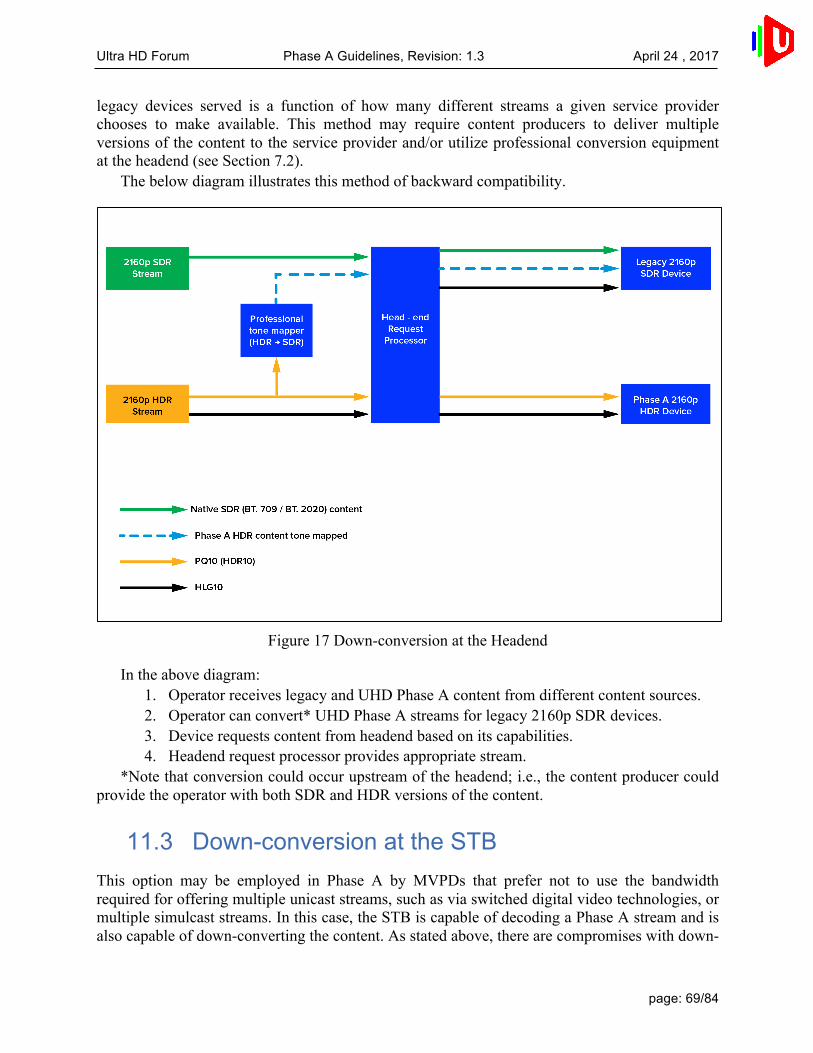
Ultra HD Forum Phase A Guidelines, Revision: 1.3 April 24 , 2017
page: 69/84
legacy devices served is a function of how many different streams a given service provider chooses to make available. This method may require content producers to deliver multiple versions of the content to the service provider and/or utilize professional conversion equipment at the headend (see Section 7.2).
The below diagram illustrates this method of backward compatibility.
Figure 17 Down-conversion at the Headend
In the above diagram: 1. Operator receives legacy and UHD Phase A content from different content sources. 2. Operator can convert* UHD Phase A streams for legacy 2160p SDR devices. 3. Device requests content from headend based on its capabilities. 4. Headend request processor provides appropriate stream.
*Note that conversion could occur upstream of the headend; i.e., the content producer could provide the operator with both SDR and HDR versions of the content.
11.3 Down-conversion at the STB This option may be employed in Phase A by MVPDs that prefer not to use the bandwidth required for offering multiple unicast streams, such as via switched digital video technologies, or multiple simulcast streams. In this case, the STB is capable of decoding a Phase A stream and is also capable of down-converting the content. As stated above, there are compromises with down-

Ultra HD Forum Phase A Guidelines, Revision: 1.3 April 24 , 2017
page: 70/84
conversion of UHD Phase A content and service providers should test the quality of the output for acceptability.
Although there is no standardized method of down-converting BT.2020 [3] to BT.709 [2], it is expected that some STBs may have this capability. STBs may also have the capability of down-converting PQ10 or HDR10 to SDR. The diagram below illustrates this method.
Figure 18 Down-conversion at the STB
Details: • The Phase A STB supports HEVC, Main 10 Profile, Level 5.1, BT.2020 [3], and HDMI
2.0a and optionally IP output. • In this example, the legacy 2160p SDR display supports BT.709 [2] but does not
supportBT.2020 [3]. o Therefore, in the diagram, the Phase A STB would convert the video from
BT.2020 [3] to BT.709 [2] before transmitting it to the legacy 2160p SDR display.
o Note that some legacy 2160p SDR displays may support BT.2020 [3] and for these displays, a Phase A STB does not need to convert from BT.2020 [3] to BT.709 before transmitting to the TV.

Ultra HD Forum Phase A Guidelines, Revision: 1.3 April 24 , 2017
page: 71/84
11.4 Spatial Resolution Up-conversion of Legacy Services
This option may be employed in Phase A by MVPDs that prefer not to use the bandwidth required for offering multiple unicast streams, and when Phase A STBs are not be able to convert a UHD Phase A stream to an appropriate format and/or with sufficient quality for display on a legacy 2160p SDR display. Phase A STBs (as well as legacy 2160p SDR displays) are expected to have the capability of upscaling 720p/1080i/1080p SDR channels to 2160p resolutions. This option requires simulcasting; however, the 720p/1080i/1080p SDR stream/service often already exists, e.g., during a transition period. In this case, the legacy 2160p SDR display gets the legacy stream and up-converts the spatial resolution to 2160p. Only the 2160p HDR display gets the UHD Phase A stream. There are compromises with up-conversion of 720p/1080i/1080p content and service providers should test the quality of the output for acceptability.
Figure 19 Spatial Resolution Up-conversion of Legacy Services
Details: • The Phase A STB decodes the 2160p HDR stream when connected to 2160p HDR
displays. • The Phase A STB decodes the 720p/1080i/1080p SDR stream when connected to
legacy 2160p SDR displays. The STB can either transmit the decoded

Ultra HD Forum Phase A Guidelines, Revision: 1.3 April 24 , 2017
page: 72/84
720p/1080i/1080p SDR video or convert the 720p/1080i/1080p SDR video to 2160p SDR video before transmitting it to the legacy 2160p SDR display.
• Note that SDR to HDR conversion, if needed, is best performed in the display device rather than in the decoder device.

Ultra HD Forum Phase A Guidelines, Revision: 1.3 April 24 , 2017
page: 73/84
11.5 Interoperability of Atmos Channel-based Immersive Audio
For emission of Atmos Channel-based Immersive Audio, an E-AC-3 encoder with ETSI 103 420 [33] functionality is required. Internally, the encoder will create a backward compatible 5.1 channel version rendered from the 7.1.4 (or 7.1.2 or 5.1.2 or 5.1.4) input. This 5.1 channel render is E-AC-3 coded as normal and information about the render, as described in ETSI 103 420 [33], is also carried. Legacy E-AC-3 decoders will reproduce the backward compatible base surround program while advanced E-AC-3 decoders, compliant with ETSI 103 420 [33] will reproduce the full 7.1.4 (or 7.1.2 or 5.1.2 or 5.1.4) immersive audio program.

Ultra HD Forum Phase A Guidelines, Revision: 1.3 April 24 , 2017
page: 74/84
12. Introduction to Annexes
The following Annexes offer information about technologies that are out of scope of Phase A, but may offer useful information to Ultra HD service implementers. In other cases, a workflow that is not in the scope Phase A is described along with technologies that might apply to that workflow. In some cases, the technologies and workflows described may apply to Phase B, in which case the information will be further detailed in the main body of a future version of the Guidelines.

Ultra HD Forum Phase A Guidelines, Revision: 1.3 April 24 , 2017
page: 75/84
13. Annex A: Over-the-Air Broadcast Use Case
Commercial deployment of Ultra HD services via OTA delivery is not expected to commence in 2016, and is thus not a Phase A use case. OTA broadcasters are anticipating Korea’s launch of terrestrial UHD TV commercial services using ATSC 3.0 in February 2017. Japan may be another adopter, for example deploying Ultra HD OTA services in 2017-18, while the U.S. and Europe may start services in roughly the 2019-20 timeframe.
The Ultra HD Forum explored this use case in anticipation of these services launching in future phases.
OTA broadcast of 2160p content is an expensive proposition in terms of pixels/Hz. Some broadcasters, such as those in Korea, may have access to sufficient spectrum to deliver Ultra HD content in 2160p resolution. However, in other parts of the world, such as the U.S. or Europe, broadcasters’ network capacity may be limited, especially if legacy HD/SD simulcasting and/or channel sharing is necessary. In this case, broadcasters may choose to offer advanced services in 1080p, 50/60fps, HDR/WCG format, which may be deployed in under 10Mbps. Where simulcasting and channel/sharing are not necessary and HEVC compression is sufficient, 2160p content can be broadcast OTA. It is possible that in some countries broadcasters will use satellite to deliver an Ultra HD experience until spectrum is allocated on terrestrial networks.
Japan has announced that 8K resolution services are on their deployment roadmap for 2018 by satellite and optical fiber. Terrestrial broadcast technologies are still in development. With technology available in 2016, 8K resolution bitrates are expected to be in the range of 100Mbps; thus, only satellite can enable the transmission of 8K resolution services. For example, in Japan BS Digital is already transmitting 8K content via satellite.
In countries where bandwidth is constrained, the expectation is that a single HDR/WCG service with direct backwards compatibility may be most desirable (i.e., not simulcast with a separate stream in SDR/BT.709). Because broadcasters target TVs directly, they must also consider backward compatibility with deployed consumer electronics or other infrastructure that is not capable of processing some aspects of Ultra HD content so simulcasting may be a necessity nonetheless.

Ultra HD Forum Phase A Guidelines, Revision: 1.3 April 24 , 2017
page: 76/84
14. Annex B: Next Generation Audio
14.1 Why Next Generation Audio? Complementing the visual enhancements that Ultra HD will bring to consumers, Next Generation Audio (NGA) will introduce compelling new audio experiences:
• Immersive – Providing the sensation of height on speakers and headphones • Personalized – Enabling consumers to tailor and interact with their listening
experience, e.g. selecting different languages or changing the dialog level • Consistent – Playback experience optimized for each consumer device, e.g. home and
mobile
14.2 What is Next Generation Audio? • NGA introduces a number of new concepts and techniques, including channel-based,
object-based, and scene-based audio delivering an immersive and personalized/interactive experience
• NGA provides greater flexibility to create and deliver content. By delivering audio as individual elements, or objects, content creators can simplify operations, reduce bandwidth, and provide a premium experience for every audience
• NGA will be delivered to consumers over a number of different distribution platforms including terrestrial, cable, and satellite broadcast, IPTV, OTT, and mobile. It could also be delivered over a hybrid of broadcast and OTT
• NGA will be experienced by consumers through headphones or speakers (e.g., TV speakers, home theater systems, sound bars)
Figure 20 NGA Distribution Overview

Ultra HD Forum Phase A Guidelines, Revision: 1.3 April 24 , 2017
page: 77/84
Figure 21 NGA Consumer Domain
14.3 Next Generation Audio Example Use Cases • Consumers will experience audio coming from overhead as well as around them
while listening through speakers at home or while on the go through headphones, giving them a richer more immersive experience in every listening environment
• Consumers can select their language preference from many more choices than they have had in the past and enjoy audio program without compromise
• Sports fans will be able to use interactive features to select their team announcer, what crowed they hear, or maybe even add in the overhead public address feed so they feel like they are at the game
• Visually impaired users may select a descriptive audio track while enjoying television to be added to the main dialog (voice over) to better understand what is happening on-screen
• Hearing impaired users may use dialog enhancement as well as the ability to control the volume of the dialog independently of other sounds to improve their listening experience
• Mobile viewers can ‘boost’ specific elements of an audio program like dialog or the ambient sound when listening in high noise environments (e.g., train stations, crowds, airports) to better understand what’s happening in a piece of audio content

Ultra HD Forum Phase A Guidelines, Revision: 1.3 April 24 , 2017
page: 78/84
15. Annex C: ICTCP Color Space
The expanding range of display technologies, from various color primaries to increasing dynamic range, is creating a marketplace where color management is becoming increasingly important if artistic intent is to be maintained. In many applications, traditional color transformations may not be possible due to limitations in bandwidth, speed, or processing power. In these cases, image processing such as blending, resizing, and color volume transform must be performed on the incoming signal. With growing color volumes and the increasing need for color processing, distortions already known to be caused by non-uniformity of standard dynamic (SDR) range non-constant-luminance (NCL) Y’C’BC’R (hue linearity and constant luminance) will become more prevalent and objectionable.
ICTCP a color representation designed for high dynamic range (HDR) and wide color gamut (WCG) imagery and is intended as an optional replacement for Non Constant Luminance Y’C’BC’R with HDR and WCG signals. ICTCP is a more perceptually uniform color representation that is based on the human visual system. The improved decorrelation of saturation, hue, and intensity make ICTCP ideal for the entire imaging chain from scene to screen. ICTCP follows the same operations as NCL Y’C’BC’R, making it a possible drop-in replacement. These color processing improvements are achieved by utilizing aspects of the human visual system and by optimizing for lines of constant hue, uniformity of just-noticeable-difference (JND) ellipses, and constant luminance. The perceptually uniform design of ICTCP allows for complex tasks such as color volume transform to be easily performed on HDR and WCG imagery with minimal error.
ICTCP is included in BT.2100 [5] and is being deployed by OTT service providers as well as implemented by numerous consumer TV manufacturers.

Ultra HD Forum Phase A Guidelines, Revision: 1.3 April 24 , 2017
page: 79/84
16. Annex D: ACES Workflow for Color and Dynamic Range
The ACES project provides a thorough workflow that can be used to model the processing of HDR/WCG video signals from source to display in a series of stages that mark the boundaries of significant transformations, each with a specific purpose. Most, if not all, Ultra HD Blu-Ray (BD-ROM 3.1) content were authored in ACES workspace.
Source code and documentation for ACES is available at: https://github.com/ampas/aces-dev/
Figure 22 ACES Workflow Model
The basic ACES workflow model stages are described in the following table.
Table 14 ACES Workflow Model
ACES Stage Purpose IDT Input Device Transform: camera format (Bayer RAW, Slog3, etc.) to
workflow color space (ACES) LMT Look Modification Transform provides an appearance such as “dark night”,
“indoor lighting”, etc. established by cinematographer. RRT Reference Rendering Transform: converts scene referred signal to display
referred signal, with knowledge of reference viewing environments and limited display ranges.
ODT Output Device Transform. Maps display referred to a specific display range (black and peak white levels), container color primaries (BT.709, BT.2020), and transfer function (gamma, PQ, HLG).
The UHDTV color grading process will start with ingesting digital camera rushes or scanned
film at whatever the useable resolution, gamut and dynamic range is available from the source material. If the source content is in a format specific to the capture device, the source signal will

Ultra HD Forum Phase A Guidelines, Revision: 1.3 April 24 , 2017
page: 80/84
undergo transformation to a more universal processing space in a stage such as the IDT depicted above.
Colorists working on UHDTV projects are likely to continue the practice of first setting the overall mood of the film or program, then deciding how particular scenes fit that mood and finally how the viewer’s interest is directed to characters, objects etc. on specific shots. A set of look-modification transforms, conceptualized in the LMT stage depicted above, reshape content according to the intent of directors, cinematographers, and colorists.
Source material will not necessarily be Rec. 2020 or Rec. 709, (unless it is a re - mastering or restoration project), because there are widely different capabilities in cameras, film stocks etc. Therefore the common starting point for colorists or compositors, will be to bring in all what’s available, as this allows more scope in post production.
The colorist or compositor will then make decisions about what to select from that available resolution, range and gamut and how to present it as “legal” PQ10 or HLG10 based content to UHDTV consumer screens, which support Rec. 2100 containers. The display rendering stages (RRT and ODT) shape content to fit within the capabilities of a range of target displays, modeled by the mastering display monitor. The colorist will re-grade content and adjust the look based on the appearance of the rendered content on the mastering display reference monitor used to preview the final appearance. A more advanced workflow configuration could account for additional distortions added by reduced integer precision, Y’CbCr color space conversion, 4:2:0 chroma resampling, and video codec quantization by feeding the output of the decoder to the reference monitor.
Additional considerations would be needed if format interoperability (back compatibility) were being attempted, for example to 4K SDR / Rec. 709 or HD SDR / Rec. 709. Producing deliverables in a Rec. 709 / HDR rendered format is not recommended and it is not clear what the long-term market use case for this would be. HDR and WCG are intrinsically linked in the HLS or RGB color spaces and most importantly also in the way we ‘see’. They are different dimensions of the unified perceptual experience.

Ultra HD Forum Phase A Guidelines, Revision: 1.3 April 24 , 2017
page: 81/84
17. Annex E: SL-HDR1
As pointed out in Sections 7.2, ETSI TS 103 433 [32] describes a method of down-conversion to generate an SDR/BT.709 signal from an HDR/WCG signal. The process supports either PQ or HLG for HDR content and can optionally deliver SDR/BT.2020 as the down-conversion target.
This ETSI specification additionally describes a mechanism for generating metadata during the down-conversion process, which may used to reconstruct HDR/WCG video in a receiver. This additional aspect of ETSI TS 103 433 [32] may come into use in Phase B. The system as a whole is called SL-HDR1.
In the Phase B SL-HDR1 system, as shown in Figure 23 the down-conversion process comprises an HDR decomposition step, which generates reconstruction metadata in addition to the SDR/BT.709 signal, making the down-conversion invertible.
For distribution, the metadata is carried in the HEVC bitstream as SEI messages, accompanying the encoded SDR/BT.709 content as described in ETSI TS 103 433 [32]. This metadata enables optional reconstruction of the HDR/WCG signal.
Once encoded, the SDR/BT.709 signal with the metadata is distributed to receivers. Legacy devices may use the SDR/BT.709 format for presentation of the SDR/BT.709 image (ignoring the metadata). If received by a decoder that recognizes the metadata and is connected to an HDR/WCG display, the metadata may be used by the decoder to reconstruct the HDR/WCG image.
This system addresses integrated decoder/displays and separate decoder/displays such as a STB connected to a display. In the case of the integrated decoder/display, if the decoder recognizes the metadata, it can use it to map the HDR/WCG image directly to its display. If not, the decoder will output the SDR/BT.709 picture. In the case of the separate decoder/display, the decoder may query the interface with the display device (e.g., HDMI) to determine whether the display is HDR/WCG-capable, and if so, use the metadata to decode the HDR/WCG image for the display. If not, the decoder decodes the SDR/BT.709 image for the display.
In any case, the SDR/BT.709 image would be presented if the metadata does not reach the decoder or cannot be interpreted for any reason. This offers particular advantages during the transition to HDR: Note that the HDR decomposition and encoding can take place in a broadcast facility immediately before emission, or earlier, when valuable to support a particular workflow. Accordingly, it is not required that metadata is transported throughout the broadcast facility to employ this the SL-HDR1 technique. However, if the SDR and metadata produced by the HDR decomposition block are carried within the broadcast facility, then the SDR signal is usable by legacy monitors and multi-viewers, even if the metadata is not. As components within the broadcast facility are upgraded over time, they can utilize the metadata when and as needed to reconstruct the HDR signal.

Ultra HD Forum Phase A Guidelines, Revision: 1.3 April 24 , 2017
page: 82/84
Figure 23 Phase B SL-HDR1 Processing, Distribution, Reconstruction, and
Presentation

Ultra HD Forum Phase A Guidelines, Revision: 1.3 April 24 , 2017
page: 83/84
18. Annex F: ISO 23001-12, Sample Variants
For Forensic Watermarking as described in Section 7.2.5.6, transport of Variants can be done by different mechanisms. One alternative is transport at the container layer
Variants metadata can be transmitted in an alternate transmission channel next to the video content at the container layer. For instance, Variants metadata could be placed within a MPEG2-TS bitstream using a dedicated Packet Identifier (PID) and using the Program Clock Reference (PCR) to synchronize the video and metadata channels. Alternately, Variants metadata could be incorporated as an extra track in an ISOBMFF file. In that case, synchronization can be achieved by aligning samples across different tracks. When Variants metadata is handled as a component separate from the video, proper care shall be taken to guarantee its protection if needed with relevant content protection techniques.
Figure 24 Transport at the container layer using a track in an ISOBMFF file
An example of how to transmit Variants metadata as an extra track in an ISOBMFF file is described in [39]12. This standard applies to file-based delivery, e.g., on physical media with embedding on the client side. The baseline principle is to define a dedicated track in an ISOBMFF file that describes how to construct watermarked video samples. For instance, a constructor for a sample indicates which portion of the video track shall be kept and which portions shall be replaced by a Variant available in the variant track. Access to the MPEG variant constructors is subject to cryptographic keys. Different users/devices will have a different sets of keys and thereby would be able to only produce different watermarked video samples using different constructors. Moreover, the Variants are double encrypted to serve as an anti-bypass
12 It shall be noted that the terminology “variants” is slightly different in the MPEG standard
and these UHD guidelines. In the MPEG standard, a variant is a full MPEG sample composed of parts of the original bitstream and parts of the Variants, as defined in this document i.e. segments of bitstream that can be used interchangeably at a given location in the bitstream.
MEDIA TRACK Movie Box Media Data Box
Track Box Sample
n
Sample
n+1
Sample Sample
VARIANT TRACK Movie Box Media Data Box
Track Box Sample
n+1
Sample
The existence of a sample in the Variants track indicate that the corresponding sample in the media track can be watermarked using this metadata
Header information required to parse the track

Ultra HD Forum Phase A Guidelines, Revision: 1.3 April 24 , 2017
page: 84/84
mechanism. A player that would not perform the watermark embedding operation would not be able to display a good quality video since some segments of the video would still be encrypted. The strong link between encryption and watermarking requires collaboration between CAS/DRM and watermarking systems, e.g., for key management and provisioning. The virtue of this design is that it enables a secure integration of the watermark embedding module on open devices outside of the secure video path or trusted execution environment.
End of Document