ultra low nox emissions condensing gas furnace …€¦ · pilot free igniter — payne’s...
TRANSCRIPT
1
Product Data
PG95ESUSINGLE--STAGE, UPFLOW/HORIZONTAL
ULTRA LOW NOX EMISSIONSCONDENSING GAS FURNACE
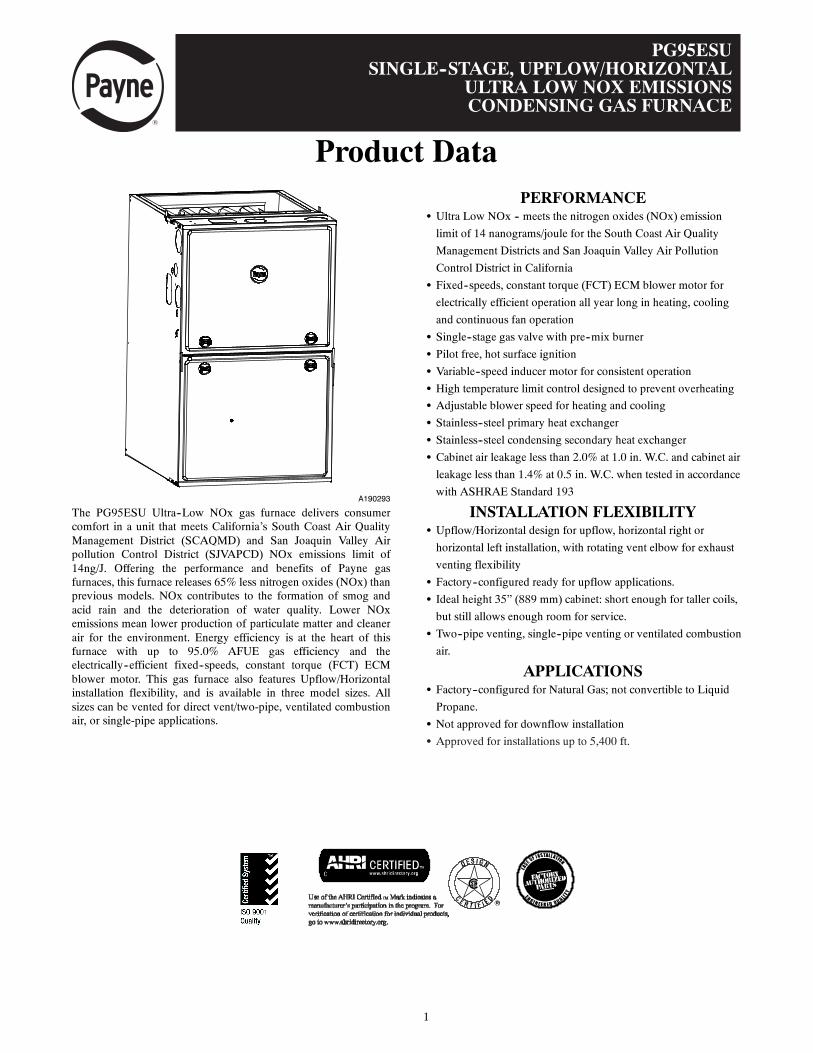
A190293
The PG95ESU Ultra--Low NOx gas furnace delivers consumercomfort in a unit that meets California’s South Coast Air QualityManagement District (SCAQMD) and San Joaquin Valley Airpollution Control District (SJVAPCD) NOx emissions limit of14ng/J. Offering the performance and benefits of Payne gasfurnaces, this furnace releases 65% less nitrogen oxides (NOx) thanprevious models. NOx contributes to the formation of smog andacid rain and the deterioration of water quality. Lower NOxemissions mean lower production of particulate matter and cleanerair for the environment. Energy efficiency is at the heart of thisfurnace with up to 95.0% AFUE gas efficiency and theelectrically--efficient fixed--speeds, constant torque (FCT) ECMblower motor. This gas furnace also features Upflow/Horizontalinstallation flexibility, and is available in three model sizes. Allsizes can be vented for direct vent/two-pipe, ventilated combustionair, or single-pipe applications.
PERFORMANCES Ultra Low NOx -- meets the nitrogen oxides (NOx) emission
limit of 14 nanograms/joule for the South Coast Air Quality
Management Districts and San Joaquin Valley Air Pollution
Control District in California
S Fixed--speeds, constant torque (FCT) ECM blower motor for
electrically efficient operation all year long in heating, cooling
and continuous fan operation
S Single--stage gas valve with pre--mix burner
S Pilot free, hot surface ignition
S Variable--speed inducer motor for consistent operation
S High temperature limit control designed to prevent overheating
S Adjustable blower speed for heating and cooling
S Stainless--steel primary heat exchanger
S Stainless--steel condensing secondary heat exchanger
S Cabinet air leakage less than 2.0% at 1.0 in. W.C. and cabinet air
leakage less than 1.4% at 0.5 in. W.C. when tested in accordance
with ASHRAE Standard 193
INSTALLATION FLEXIBILITYS Upflow/Horizontal design for upflow, horizontal right or
horizontal left installation, with rotating vent elbow for exhaust
venting flexibility
S Factory--configured ready for upflow applications.
S Ideal height 35” (889 mm) cabinet: short enough for taller coils,
but still allows enough room for service.
S Two--pipe venting, single--pipe venting or ventilated combustion
air.
APPLICATIONSS Factory--configured for Natural Gas; not convertible to Liquid
Propane.
S Not approved for downflow installation
S Approved for installations up to 5,400 ft.
2
FURNACE
CASINGDIMENSIONS (IN.) RATED
HEATINGOUTPUT†
BTUH
AFUEENERGYSTARr
HEATING AIRFLOW COOLINGCFM @ 0.5
ESP(in. W.C.)
MOTORHP -
SPEEDTAPS
H D WUPFLOW/
HORIZONTALHEATING
CFM‡
HEATINGESP
(in. W.C.)
PG95ESUA48060B 35 29.50 17.50 58,000 95% YES 1205 0.12 1515 3/4 - 5
PG95ESUA60080C 35 29.50 21.00 78,000 95% YES 1790 0.12 2025 1 - 5
PG95ESUA60100C 35 29.50 21.00 96,000 95% YES 1880 0.15 2065 1 - 5
† Capacity in accordance with DOE test procedures. Ratings are position dependent. See rating plate.‡ Heating CFM at factory default blower motor heating tap settings.ESP --- External Static Pressure
MODEL NUMBER NOMENCLATURE
A190405
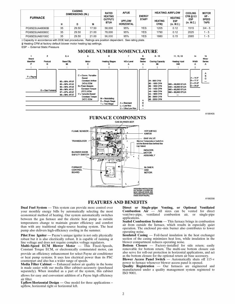
FURNACE COMPONENTS
A190258
FEATURES AND BENEFITSDual Fuel System — This system can provide more control overyour monthly energy bills by automatically selecting the mosteconomical method of heating. Our system automatically switchesbetween the gas furnace and the electric heat pump as outsidetemperatures change to maintain greater efficiency and comfortthan with any traditional single-source heating system. The heatpump also delivers high-efficiency cooling in the summer.
Pilot Free Igniter— Payne’s unique igniter is not only physicallyrobust but it is also electrically robust. It is capable of running atline voltage and does not require complex voltage regulators.Multi--Speed ECM Blower Motor — This Fixed--Speeds,Constant Torque ECM, or electronically commutated motor, canprovide an efficiency enhancement for select Payne air conditioneror heat pump systems. It uses less electrical power than its PSCcounterpart and also has a wider range of speeds.Media Filter Cabinet— Enhanced indoor air quality in the homeis made easier with our media filter cabinet--accessory (purchasedseparately). When installed as a part of the system, this cabinetallows for easy and convenient addition of a Payne high efficiencyair filter.Upflow/Horizontal Design — One model for three applications –upflow, horizontal right or horizontal left.
Direct or Single-pipe Venting, or Optional VentilatedCombustion Air — All sizes can be vented for directvent/two-pipe, ventilated combustion air, or single-pipeapplications.Sealed Combustion System— This furnace brings in combustionair from outside the furnace, which results in especially quietoperation. The enclosed pre--mix burner also contributes to loweroperating noise.Insulated Casing — Foil-faced insulation in the heat exchangersection of the casing minimizes heat loss, while insulation in theblower compartment reduces operating noise.Bottom Closure — Factory-installed for side return; easilyremovable for bottom return. The multi-use bottom closure canalso serve for roll-out protection in horizontal applications, and actas the bottom closure for the optional return air base accessory.Blower Access Panel Switch — Automatically shuts off 115-vpower to furnace whenever blower access panel is opened.Quality Registration — Our furnaces are engineered andmanufactured under a quality management system registered toISO 9001.
3
SPECIFICATIONSThe furnace should be sized to provide 100 percent of the designheating load requirement plus any margin that occurs because offurnace model size capacity increments. None of the furnacemodel sizes can be used if the heating load is less than half of thefurnaces model’s output capacity. Use Air ConditioningContractors of America (Manual J and S); American Society ofHeating, Refrigerating, and Air-Conditioning Engineers; or other
approved engineering method to calculate heating load estimatesand select the furnace. Excessive oversizing of the furnace maycause the furnace and/or vent to fail prematurely, customerdiscomfort and/or vent freezing.
Failure to follow these guidelines is considered faulty installationand/or misapplication of the furnace; and resulting failure, damage,or repairs may impact warranty coverage.
Heating Capacity and Efficiency 48060B 60080C 60100CInput Heating (BTUH) 60,000 80,000 100,000Output Heating (BTUH) 58,000 78,000 96,000Certified Temperature RiseRange ºF (ºC) Heating 30 --- 60
(17 --- 33)30 --- 60(17 --- 33)
35 --- 65(19 --- 36)
Airflow Capacity and Blower Data
Rated External StaticPressure (in. w.c.)
Heating 0.12 0.12 0.15Cooling 0.5 0.5 0.5
Airflow Delivery @ RatedESP (CFM)
Heating 1205 1790 1880Cooling 1515 2025 2065
Cooling Capacity(tons) @ CFM/ton
400 CFM/ton 3.5 5 5350 CFM/ton 4 5.5 5.5
Direct---Drive Motor Type Electronically Commutated Motor (ECM)Direct---Drive Motor HP 3/4 1 1Motor Full Load Amps 8.8 11.5 11.7RPM Range 570 --- 1400 570 --- 1400 400 --- 1300Speed Selections 5 5 5Blower Wheel Dia x Width in. 11 x 8 11 x 10 11 x 10Filter Used for Certified Watt Data KGAWF**06UFR
Electrical DataInput Voltage Volts---Hertz---Phase 115---60---1Operating Voltage Range Min---Max 104---127Maximum Input Amps Amps 10.9 13.6 13.8Unit Ampacity Amps 14.2 17.6 17.8Minimum Wire Size AWG 14 12 12Maximum Wire Length@Minimum Wire Size Feet 26.2 32.8 32.3
Maximum Fuse/Ckt Bkr(Time---Delay TypeRecommended)
Amps 15 20 20
Transformer Capacity (24 VAC output) 40 VA
External Control PowerAvailable
Heating 21.8 VACooling 34 VA
ControlsGas Connection Size 1/2” - NPT
Gas Valve (Redundant) Manufacturer White Rodgers
Minimum Inlet Gas pressure (in. wc) 4.50
Maximum Inlet Gas pressure (in. wc) 13.60
Manufactured (Mobile) Home Kit Not approved for Manufactured Home use
Ignition Device Silicon Nitride
Heating Blower Control (Heating Off-Delay) Adjustable: 90, 120, 150, 180 seconds
Cooling Blower Control (Time Delay Relay) 90 seconds
Communication System noneThermostat Connections Com 24V, R, W, G, Y
Accessory Connections EAC (115vac); HUM (115vac); 1-stg AC (via Y)
4
INSTALLATION CONSIDERATIONSRefer to Installation Instructions for complete installation requirements.
Evaporator Coil Spacer or Shield Requirements
Type of Coil Install Flush to Furnace Install with8---in. Spacer
Install with MetalShield
Furnace Manufacturer’sN Coil Allowed Not Required Not Required
Furnace Manufacturer’sA Coil Not Allowed
Allowed(Except 100k BTU size in Horizontal
Right --- MUST use shield)
Allowed(See Note 2)
3rd Party Coil --- Factory Shielded (See Note 1) Allowed Not Required Not Required
3rd Party Coil ---Unshielded Not Allowed
Allowed(Except 100k BTU size in Horizontal
Right --- MUST use shield)
Allowed(See Note 3)
NOTE:1. 3rd Party Coils that are factory--supplied with a metallic shield over the plastic composite drain pan must completely shield all plasticcomposite materials from direct exposure to any part of the heat exchanger. Consult with 3rd Party Manufacturer to ensure coil isproperly shielded. Coils that are only partially shielded should be treated as un--shielded and require a spacer.
2. Field--fabricated metallic shield must completely shield all plastic composite materials from direct exposure to any part of the heatexchanger. Coils that are only partially shielded should be treated as un--shielded and require a spacer.
3. For 3rd party unshielded coils, consult manufacturer for design of a field--fabricated shield that completely shields all plastic compositematerials from direct exposure to any part of the heat exchanger.
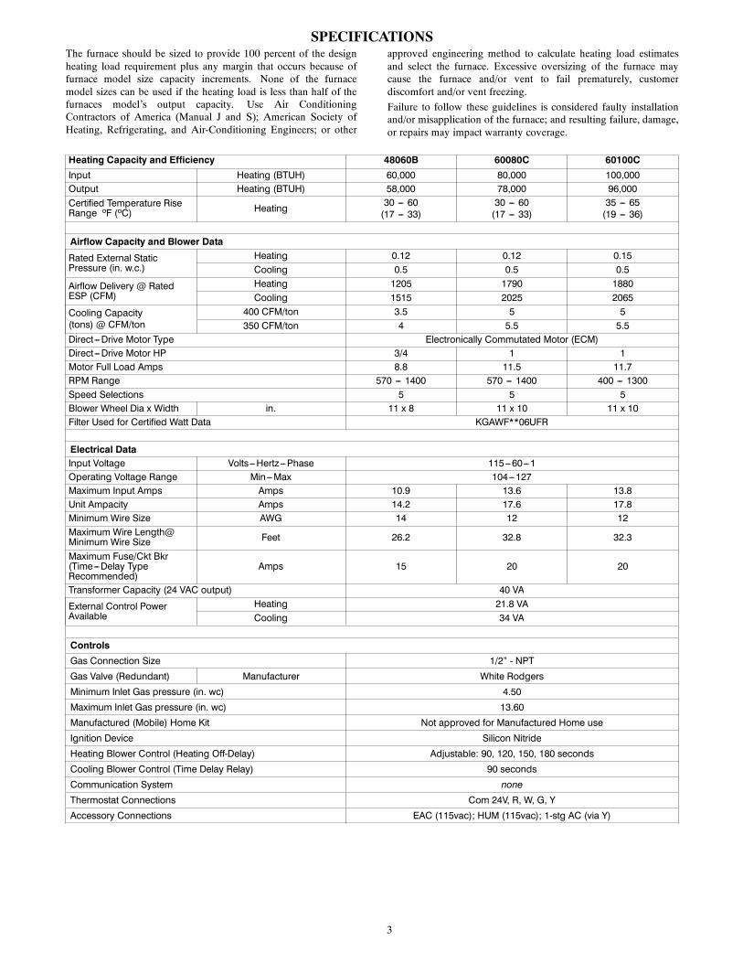
CONDENSATE TRAP CLEARANCES
Representative drawing only, some models may vary.
FACTORY SUPPLIEDCONDENSATEFLOAT SWITCH
FACTORY SUPPLIED3/4” PVC TEE DRAIN
DRAIN TEE CAN BEROTATED FORWARDFOR NARROW IN-STALLATIONS
TO OPEN DRAIN
A190317
Trap Clearance in Upflow Application
Representative drawing only, some models may vary.
FACTORY SUPPLIEDCONDENSATEFLOAT SWITCH
FACTORY SUPPLIED3/4” PVC TEE DRAIN
FIELD SUPPLIED
5---3/4”15”
A190315
15” Trap Clearance in Horizontal Application(Note: Drain line can be run horizontally or vertically)
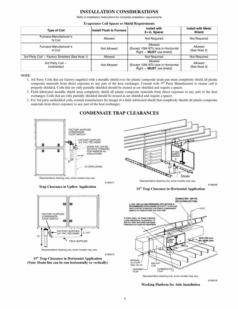
Representative drawing only, some models may vary.
A190356
15” Trap Clearance in Horizontal Application
Representative drawing only, some models may vary.
A190318
Working Platform for Attic Installation
5
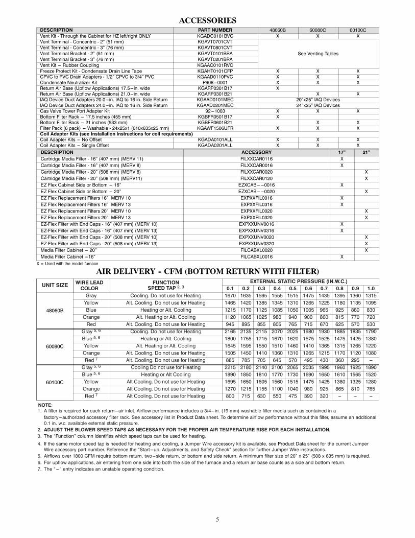
ACCESSORIESDESCRIPTION PART NUMBER 48060B 60080C 60100CVent Kit - Through the Cabinet for HZ left/right ONLY KGADC0101BVC X X XVent Terminal - Concentric - 2” (51 mm) KGAVT0701CVT
See Venting TablesVent Terminal - Concentric - 3” (76 mm) KGAVT0801CVTVent Terminal Bracket - 2” (51 mm) KGAVT0101BRAVent Terminal Bracket - 3” (76 mm) KGAVT0201BRAVent Kit --- Rubber Coupling KGAAC0101RVCFreeze Protect Kit - Condensate Drain Line Tape KGAHT0101CFP X X XCPVC to PVC Drain Adapters - 1/2” CPVC to 3/4” PVC KGAAD0110PVC X X XCondensate Neutralizer Kit P908---0001 X X XReturn Air Base (Upflow Applications) 17.5---in. wide KGARP0301B17 XReturn Air Base (Upflow Applications) 21.0---in. wide KGARP0301B21 X XIAQ Device Duct Adapters 20.0---in. IAQ to 16 in. Side Return KGAAD0101MEC 20”x25” IAQ DevicesIAQ Device Duct Adapters 24.0---in. IAQ to 16 in. Side Return KGAAD0201MEC 24”x25” IAQ DevicesGas Valve Tower Port Adapter Kit 92---1003 X X XBottom Filter Rack --- 17.5 inches (455 mm) KGBFR0501B17 XBottom Filter Rack --- 21 inches (533 mm) KGBFR0601B21 X XFilter Pack (6 pack) --- Washable - 24x25x1 (610x635x25 mm) KGAWF1506UFR X X XCoil Adapter Kits (see Installation Instructions for coil requirements)Coil Adapter Kits --- No Offset KGADA0101ALL X X XCoil Adapter Kits --- Single Offset KGADA0201ALL X X XDESCRIPTION ACCESSORY 17” 21”Cartridge Media Filter - 16” (407 mm) (MERV 11) FILXXCAR0116 XCartridge Media Filter - 16” (407 mm) (MERV 8) FILXXCAR0016 XCartridge Media Filter - 20” (508 mm) (MERV 8) FILXXCAR0020 XCartridge Media Filter - 20” (508 mm) (MERV11) FILXXCAR0120 XEZ Flex Cabinet Side or Bottom --- 16” EZXCAB--- ---0016 XEZ Flex Cabinet Side or Bottom --- 20” EZXCAB--- ---0020 XEZ Flex Replacement Filters 16” MERV 10 EXPXXFIL0016 XEZ Flex Replacement Filters 16” MERV 13 EXPXXFIL0316 XEZ Flex Replacement Filters 20” MERV 10 EXPXXFIL0020 XEZ Flex Replacement Filters 20” MERV 13 EXPXXFIL0320 XEZ-Flex Filter with End Caps - 16” (407 mm) (MERV 10) EXPXXUNV0016 XEZ-Flex Filter with End Caps - 16” (407 mm) (MERV 13) EXPXXUNV0316 XEZ-Flex Filter with End Caps - 20” (508 mm) (MERV 10) EXPXXUNV0020 XEZ-Flex Filter with End Caps - 20” (508 mm) (MERV 13) EXPXXUNV0320 XMedia Filter Cabinet --- 20” FILCABXL0020 XMedia Filter Cabinet ---16” FILCABXL0016 XX = Used with the model furnace
AIR DELIVERY -- CFM (BOTTOM RETURN WITH FILTER)
UNIT SIZE WIRE LEADCOLOR
FUNCTIONSPEED TAP 2, 3
EXTERNAL STATIC PRESSURE (IN.W.C.)0.1 0.2 0.3 0.4 0.5 0.6 0.7 0.8 0.9 1.0
48060B
Gray Cooling. Do not use for Heating 1670 1635 1595 1555 1515 1475 1435 1395 1360 1315Yellow Alt. Cooling. Do not use for Heating 1465 1420 1385 1345 1310 1265 1225 1180 1135 1095Blue Heating or Alt. Cooling 1215 1170 1125 1085 1050 1005 965 925 880 830Orange Alt. Heating or Alt. Cooling 1120 1065 1025 980 940 900 860 815 770 720Red Alt. Cooling. Do not use for Heating 945 895 855 805 765 715 670 625 570 530
60080C
Gray 5, 6 Cooling. Do not use for Heating 2165 2135 2115 2070 2025 1980 1930 1885 1835 1790Blue 5, 6 Heating or Alt. Cooling 1800 1755 1715 1670 1620 1575 1525 1475 1425 1380Yellow Alt. Heating or Alt. Cooling 1645 1595 1550 1510 1460 1410 1365 1315 1265 1220Orange Alt. Cooling. Do not use for Heating 1505 1450 1410 1360 1310 1265 1215 1170 1120 1080Red 7 Alt. Cooling. Do not use for Heating 885 785 705 645 570 495 430 360 295 ---
60100C
Gray 5, 6 Cooling Do not use for Heating 2215 2180 2140 2100 2065 2035 1995 1960 1925 1890Blue 5, 6 Heating or Alt Cooling 1890 1850 1810 1770 1730 1690 1650 1610 1565 1520Yellow Alt Cooling. Do not use for Heating 1695 1650 1605 1560 1515 1475 1425 1380 1325 1280Orange Alt Cooling. Do not use for Heating 1270 1215 1155 1100 1040 980 925 865 810 765Red 7 Alt Cooling. Do not use for Heating 800 715 630 550 475 390 320 --- --- ---
NOTE:1. A filter is required for each return ---air inlet. Airflow performance includes a 3/4---in. (19 mm) washable filter media such as contained in afactory---authorized accessory filter rack. See accessory list in Product Data sheet. To determine airflow performance without this filter, assume an additional0.1 in. w.c. available external static pressure.
2. ADJUST THE BLOWER SPEED TAPS AS NECESSARY FOR THE PROPER AIR TEMPERATURE RISE FOR EACH INSTALLATION.3. The “Function” column identifies which speed taps can be used for heating.
4. If the same motor speed tap is needed for heating and cooling, a Jumper Wire accessory kit is available, see Product Data sheet for the current JumperWire accessory part number. Reference the “Start ---up, Adjustments, and Safety Check” section for further Jumper Wire instructions.
5. Airflows over 1800 CFM require bottom return, two---side return, or bottom and side return. A minimum filter size of 20” x 25” (508 x 635 mm) is required.6. For upflow applications, air entering from one side into both the side of the furnace and a return air base counts as a side and bottom return.7. The “---” entry indicates an unstable operating condition.
6
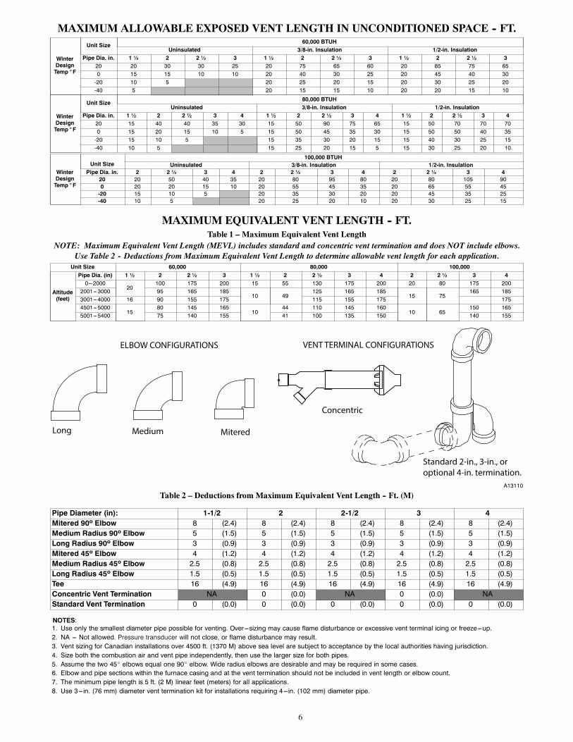
MAXIMUM ALLOWABLE EXPOSED VENT LENGTH IN UNCONDITIONED SPACE -- FT.
WinterDesignTemp ° F
Unit Size 60,000 BTUHUninsulated 3/8-in. Insulation 1/2-in. Insulation
Pipe Dia. in. 1 ½ 2 2 ½ 3 1 ½ 2 2 ½ 3 1 ½ 2 2 ½ 320 20 30 30 25 20 75 65 60 20 85 75 650 15 15 10 10 20 40 30 25 20 45 40 30-20 10 5 20 25 20 15 20 30 25 20-40 5 20 15 15 10 20 20 15 10
WinterDesignTemp ° F
Unit Size 80,000 BTUHUninsulated 3/8-in. Insulation 1/2-in. Insulation
Pipe Dia. in. 1 ½ 2 2 ½ 3 4 1 ½ 2 2 ½ 3 4 1 ½ 2 2 ½ 3 420 15 40 40 35 30 15 50 90 75 65 15 50 70 70 700 15 20 15 10 5 15 50 45 35 30 15 50 50 40 35-20 15 10 5 15 35 30 20 15 15 40 30 25 15-40 10 5 15 25 20 15 5 15 30 25 20 10
WinterDesignTemp ° F
Unit Size100,000 BTUH
Uninsulated 3/8-in. Insulation 1/2-in. InsulationPipe Dia. in. 2 2 ½ 3 4 2 2 ½ 3 4 2 2 ½ 3 4
20 20 50 40 35 20 80 95 80 20 80 105 900 20 20 15 10 20 55 45 35 20 65 55 45-20 15 10 5 20 35 30 20 20 45 35 25-40 10 5 20 25 20 10 20 30 25 15
MAXIMUM EQUIVALENT VENT LENGTH -- FT.Table 1 – Maximum Equivalent Vent Length
NOTE: Maximum Equivalent Vent Length (MEVL) includes standard and concentric vent termination and does NOT include elbows.Use Table 2 - Deductions from Maximum Equivalent Vent Length to determine allowable vent length for each application.Unit Size 60,000 80,000 100,000
Altitude(feet)
Pipe Dia. (in) 1 ½ 2 2 ½ 3 1 ½ 2 2 ½ 3 4 2 2 ½ 3 40---2000
20100 175 200 15 55 130 175 200 20 80 175 200
2001---3000 95 165 18510 49
125 165 18515 75
165 1853001---4000 16 90 155 175 115 155 175 1754501---5000
1580 145 165
1044 110 145 160
10 65150 165
5001---5400 75 140 155 41 100 135 150 140 155
Long Medium Mitered
Concentric
Standard 2-in., 3-in., or optional 4-in. termination.
ELBOW CONFIGURATIONS VENT TERMINAL CONFIGURATIONS
A13110
Table 2 – Deductions from Maximum Equivalent Vent Length -- Ft. (M)
Pipe Diameter (in): 1-1/2 2 2-1/2 3 4Mitered 90º Elbow 8 (2.4) 8 (2.4) 8 (2.4) 8 (2.4) 8 (2.4)Medium Radius 90º Elbow 5 (1.5) 5 (1.5) 5 (1.5) 5 (1.5) 5 (1.5)Long Radius 90º Elbow 3 (0.9) 3 (0.9) 3 (0.9) 3 (0.9) 3 (0.9)Mitered 45º Elbow 4 (1.2) 4 (1.2) 4 (1.2) 4 (1.2) 4 (1.2)Medium Radius 45º Elbow 2.5 (0.8) 2.5 (0.8) 2.5 (0.8) 2.5 (0.8) 2.5 (0.8)Long Radius 45º Elbow 1.5 (0.5) 1.5 (0.5) 1.5 (0.5) 1.5 (0.5) 1.5 (0.5)Tee 16 (4.9) 16 (4.9) 16 (4.9) 16 (4.9) 16 (4.9)Concentric Vent Termination NA 0 (0.0) NA 0 (0.0) NAStandard Vent Termination 0 (0.0) 0 (0.0) 0 (0.0) 0 (0.0) 0 (0.0)
NOTES:1. Use only the smallest diameter pipe possible for venting. Over ---sizing may cause flame disturbance or excessive vent terminal icing or freeze---up.2. NA --- Not allowed. Pressure transducer will not close, or flame disturbance may result.3. Vent sizing for Canadian installations over 4500 ft. (1370 M) above sea level are subject to acceptance by the local authorities having jurisdiction.4. Size both the combustion air and vent pipe independently, then use the larger size for both pipes.5. Assume the two 45_ elbows equal one 90_ elbow. Wide radius elbows are desirable and may be required in some cases.6. Elbow and pipe sections within the furnace casing and at the vent termination should not be included in vent length or elbow count.7. The minimum pipe length is 5 ft. (2 M) linear feet (meters) for all applications.8. Use 3---in. (76 mm) diameter vent termination kit for installations requiring 4---in. (102 mm) diameter pipe.
7
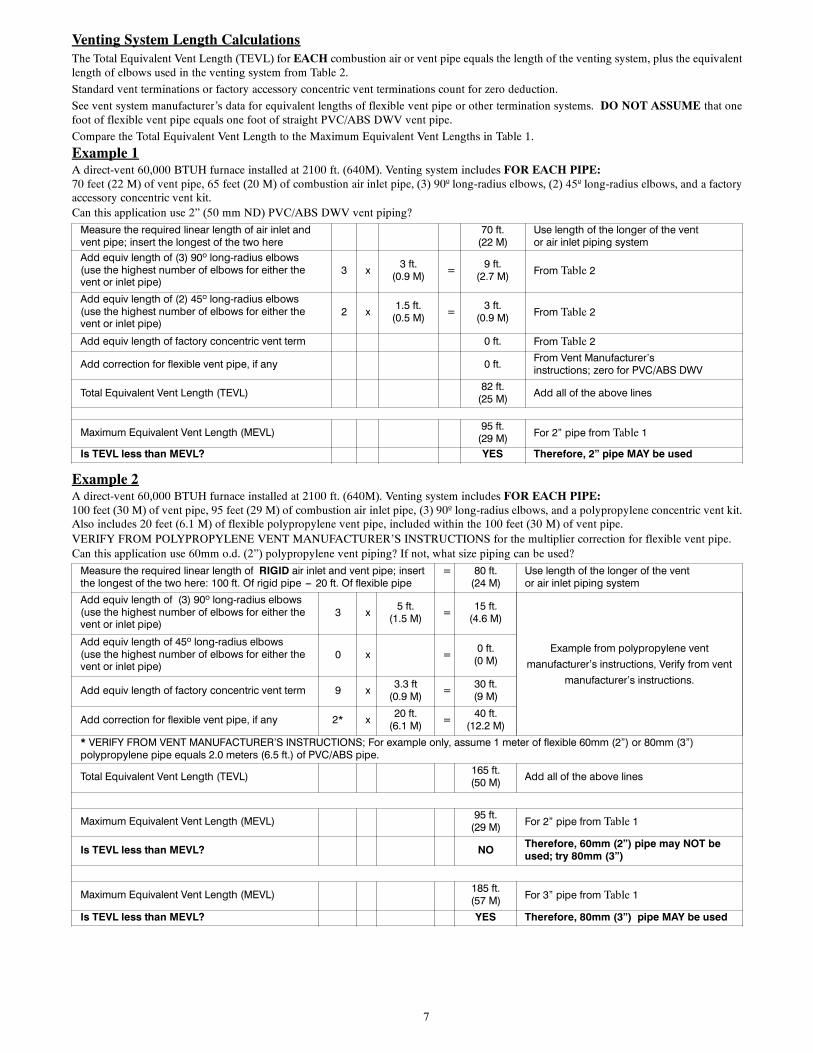
Venting System Length CalculationsThe Total Equivalent Vent Length (TEVL) for EACH combustion air or vent pipe equals the length of the venting system, plus the equivalentlength of elbows used in the venting system from Table 2.
Standard vent terminations or factory accessory concentric vent terminations count for zero deduction.
See vent system manufacturer’s data for equivalent lengths of flexible vent pipe or other termination systems. DO NOT ASSUME that onefoot of flexible vent pipe equals one foot of straight PVC/ABS DWV vent pipe.
Compare the Total Equivalent Vent Length to the Maximum Equivalent Vent Lengths in Table 1.
Example 1A direct-vent 60,000 BTUH furnace installed at 2100 ft. (640M). Venting system includes FOR EACH PIPE:70 feet (22 M) of vent pipe, 65 feet (20 M) of combustion air inlet pipe, (3) 90º long-radius elbows, (2) 45º long-radius elbows, and a factoryaccessory concentric vent kit.Can this application use 2” (50 mm ND) PVC/ABS DWV vent piping?
Measure the required linear length of air inlet andvent pipe; insert the longest of the two here
70 ft.(22 M)
Use length of the longer of the ventor air inlet piping system
Add equiv length of (3) 90º long-radius elbows(use the highest number of elbows for either thevent or inlet pipe)
3 x 3 ft.(0.9 M) = 9 ft.
(2.7 M) From Table 2
Add equiv length of (2) 45º long-radius elbows(use the highest number of elbows for either thevent or inlet pipe)
2 x 1.5 ft.(0.5 M) = 3 ft.
(0.9 M) From Table 2
Add equiv length of factory concentric vent term 0 ft. From Table 2
Add correction for flexible vent pipe, if any 0 ft. From Vent Manufacturer’sinstructions; zero for PVC/ABS DWV
Total Equivalent Vent Length (TEVL) 82 ft.(25 M) Add all of the above lines
Maximum Equivalent Vent Length (MEVL) 95 ft.(29 M) For 2” pipe from Table 1
Is TEVL less than MEVL? YES Therefore, 2” pipe MAY be used
Example 2A direct-vent 60,000 BTUH furnace installed at 2100 ft. (640M). Venting system includes FOR EACH PIPE:100 feet (30 M) of vent pipe, 95 feet (29 M) of combustion air inlet pipe, (3) 90º long-radius elbows, and a polypropylene concentric vent kit.Also includes 20 feet (6.1 M) of flexible polypropylene vent pipe, included within the 100 feet (30 M) of vent pipe.VERIFY FROM POLYPROPYLENE VENT MANUFACTURER’S INSTRUCTIONS for the multiplier correction for flexible vent pipe.Can this application use 60mm o.d. (2”) polypropylene vent piping? If not, what size piping can be used?
Measure the required linear length of RIGID air inlet and vent pipe; insertthe longest of the two here: 100 ft. Of rigid pipe --- 20 ft. Of flexible pipe
= 80 ft.(24 M)
Use length of the longer of the ventor air inlet piping system
Add equiv length of (3) 90º long-radius elbows(use the highest number of elbows for either thevent or inlet pipe)
3 x 5 ft.(1.5 M) = 15 ft.
(4.6 M)
Example from polypropylene ventmanufacturer’s instructions, Verify from vent
manufacturer’s instructions.
Add equiv length of 45º long-radius elbows(use the highest number of elbows for either thevent or inlet pipe)
0 x = 0 ft.(0 M)
Add equiv length of factory concentric vent term 9 x 3.3 ft(0.9 M) = 30 ft.
(9 M)
Add correction for flexible vent pipe, if any 2* x 20 ft.(6.1 M) = 40 ft.
(12.2 M)* VERIFY FROM VENT MANUFACTURER’S INSTRUCTIONS; For example only, assume 1 meter of flexible 60mm (2”) or 80mm (3”)polypropylene pipe equals 2.0 meters (6.5 ft.) of PVC/ABS pipe.
Total Equivalent Vent Length (TEVL) 165 ft.(50 M) Add all of the above lines
Maximum Equivalent Vent Length (MEVL) 95 ft.(29 M) For 2” pipe from Table 1
Is TEVL less than MEVL? NO Therefore, 60mm (2”) pipe may NOT beused; try 80mm (3”)
Maximum Equivalent Vent Length (MEVL) 185 ft.(57 M) For 3” pipe from Table 1
Is TEVL less than MEVL? YES Therefore, 80mm (3”) pipe MAY be used
8
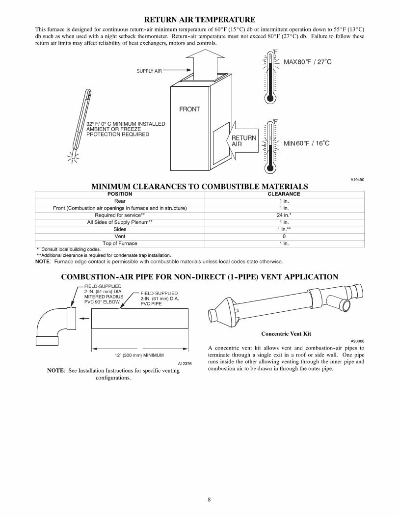
RETURN AIR TEMPERATUREThis furnace is designed for continuous return--air minimum temperature of 60_F (15_C) db or intermittent operation down to 55_F (13_C)db such as when used with a night setback thermometer. Return--air temperature must not exceed 80_F (27_C) db. Failure to follow thesereturn air limits may affect reliability of heat exchangers, motors and controls.
60
80 / 27˚C
/ 16˚C
SUPPLY AIR
A10490
MINIMUM CLEARANCES TO COMBUSTIBLE MATERIALSPOSITION CLEARANCE
Rear 1 in.Front (Combustion air openings in furnace and in structure) 1 in.
Required for service** 24 in.*All Sides of Supply Plenum** 1 in.
Sides 1 in.**Vent 0
Top of Furnace 1 in.* Consult local building codes.**Additional clearance is required for condensate trap installation.NOTE: Furnace edge contact is permissible with combustible materials unless local codes state otherwise.
COMBUSTION--AIR PIPE FOR NON--DIRECT (1--PIPE) VENT APPLICATION
FIELD-SUPPLIED2-IN. (51 mm) DIA.PVC PIPE
FIELD-SUPPLIED2-IN. (51 mm) DIA.MITERED RADIUSPVC 90° ELBOW
12” (300 mm) MINIMUM
A12376
NOTE: See Installation Instructions for specific ventingconfigurations.
Concentric Vent KitA93086
A concentric vent kit allows vent and combustion--air pipes toterminate through a single exit in a roof or side wall. One piperuns inside the other allowing venting through the inner pipe andcombustion air to be drawn in through the outer pipe.
9
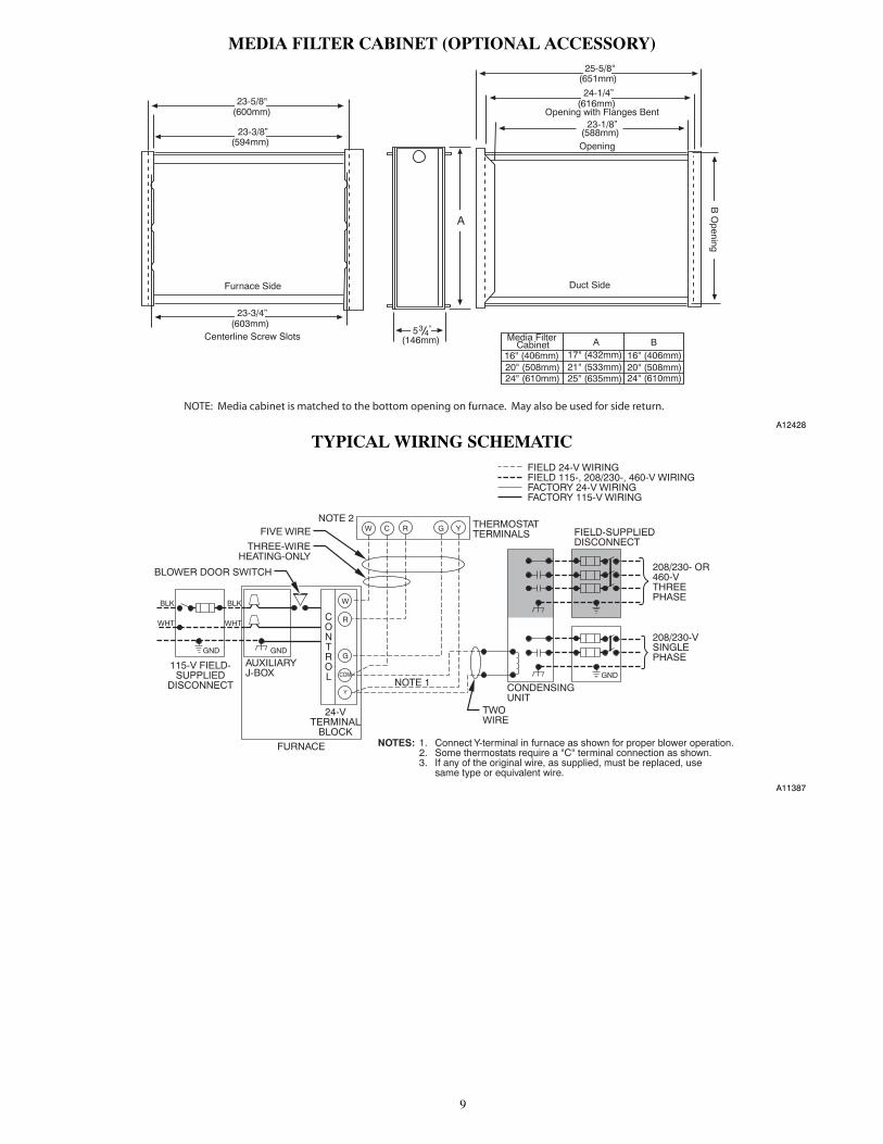
MEDIA FILTER CABINET (OPTIONAL ACCESSORY)
Media FilterCabinet A B
16" (406mm)20" (508mm)24" (610mm)
17" (432mm)
Furnace Side
Centerline Screw Slots
23-3/4”
23-3/8”
23-5/8"
534
Duct Side
Opening
Opening with Flanges Bent
24-1/4”
25-5/8"
B O
pening
A
"
(600mm)
(594mm)
(603mm)
(146mm)
(651mm)
(616mm)
23-1/8”(588mm)
16" (406mm)20" (508mm)24" (610mm)
21" (533mm)25" (635mm)
NOTE: Media cabinet is matched to the bottom opening on furnace. May also be used for side return.
A12428
TYPICAL WIRING SCHEMATIC
115-V FIELD-SUPPLIED
DISCONNECT
AUXILIARYJ-BOX
24-VTERMINAL
BLOCK
THREE-WIREHEATING-ONLY
FIVE WIRE
NOTE 1
NOTE 2FIELD-SUPPLIEDDISCONNECT
CONDENSINGUNIT
TWOWIRE
FURNACE
CONTROL
R
G
COM
W C R G Y
GND
GND
FIELD 24-V WIRINGFIELD 115-, 208/230-, 460-V WIRINGFACTORY 24-V WIRINGFACTORY 115-V WIRING
208/230- OR460-VTHREEPHASE
208/230-VSINGLEPHASE
BLOWER DOOR SWITCH
WHT
BLK
WHT
BLK
NOTES: Connect Y-terminal in furnace as shown for proper blower operation.Some thermostats require a "C" terminal connection as shown.If any of the original wire, as supplied, must be replaced, usesame type or equivalent wire.
W
Y
GND
THERMOSTATTERMINALS
1.2.3.
A11387
10
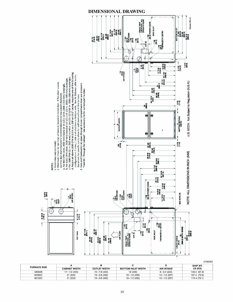
DIMENSIONAL DRAWING
A190253
FURNACE SIZEA B C D SHIP WT.
LB (KG)CABINET WIDTH OUTLET WIDTH BOTTOM INLET WIDTH AIR INTAKE48060B 17---1/2 (445) 15---7/8 (403) 16 (406) 8---3/4 (222) 149.4 (67.8)60080C 21 (533) 19---3/8 (492) 19---1/2 (495) 10---1/2 (267) 167.4 (75.9)60100C 21 (533) 19---3/8 (492) 19---1/2 (495) 10---1/2 (267) 174.4 (79.1)
11
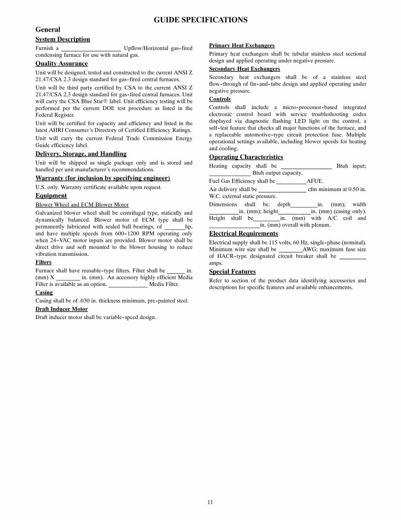
GUIDE SPECIFICATIONSGeneralSystem DescriptionFurnish a ____________________ Upflow/Horizontal gas--firedcondensing furnace for use with natural gas.
Quality AssuranceUnit will be designed, tested and constructed to the current ANSI Z21.47/CSA 2.3 design standard for gas--fired central furnaces.
Unit will be third party certified by CSA to the current ANSI Z21.47/CSA 2.3 design standard for gas--fired central furnaces. Unitwill carry the CSA Blue StarR label. Unit efficiency testing will beperformed per the current DOE test procedure as listed in theFederal Register.
Unit will be certified for capacity and efficiency and listed in thelatest AHRI Consumer’s Directory of Certified Efficiency Ratings.
Unit will carry the current Federal Trade Commission EnergyGuide efficiency label.
Delivery, Storage, and HandlingUnit will be shipped as single package only and is stored andhandled per unit manufacturer’s recommendations.
Warranty (for inclusion by specifying engineer)U.S. only. Warranty certificate available upon request.
EquipmentBlower Wheel and ECM Blower Motor
Galvanized blower wheel shall be centrifugal type, statically anddynamically balanced. Blower motor of ECM type shall bepermanently lubricated with sealed ball bearings, of _______hp,and have multiple speeds from 600--1200 RPM operating onlywhen 24--VAC motor inputs are provided. Blower motor shall bedirect drive and soft mounted to the blower housing to reducevibration transmission.
FiltersFurnace shall have reusable--type filters. Filter shall be ______ in.(mm) X ________ in. (mm). An accessory highly efficient MediaFilter is available as an option. _____________ Media Filter.
CasingCasing shall be of .030 in. thickness minimum, pre--painted steel.
Draft Inducer MotorDraft inducer motor shall be variable--speed design.
Primary Heat ExchangersPrimary heat exchangers shall be tubular stainless steel sectionaldesign and applied operating under negative pressure.
Secondary Heat ExchangersSecondary heat exchangers shall be of a stainless steelflow--through of fin--and--tube design and applied operating undernegative pressure.
ControlsControls shall include a micro--processor--based integratedelectronic control board with service troubleshooting codesdisplayed via diagnostic flashing LED light on the control, aself--test feature that checks all major functions of the furnace, anda replaceable automotive--type circuit protection fuse. Multipleoperational settings available, including blower speeds for heatingand cooling.
Operating CharacteristicsHeating capacity shall be _________________ Btuh input;______________ Btuh output capacity.
Fuel Gas Efficiency shall be __________AFUE.
Air delivery shall be ________________ cfm minimum at 0.50 in.W.C. external static pressure.
Dimensions shall be: depth_________in. (mm); width__________in. (mm); height___________in. (mm) (casing only).Height shall be_________in. (mm) with A/C coil and_________________in. (mm) overall with plenum.
Electrical RequirementsElectrical supply shall be 115 volts, 60 Hz, single--phase (nominal).Minimum wire size shall be ________AWG; maximum fuse sizeof HACR--type designated circuit breaker shall be _________amps.
Special FeaturesRefer to section of the product data identifying accessories anddescriptions for specific features and available enhancements.

12
E2019 Payne Heating & Cooling Systems D 7310 W. Morris St. D Indianapolis, IN 46231 Edition Date: 12/19
Manufacturer reserves the right to change, at any time, specifications and designs without notice and without obligations.
Catalog No: SS---PG95ESU---03Replaces: SS---PG95ESU---02